US6205230B1 - Optical contour digitizer - Google Patents
Optical contour digitizerDownload PDFInfo
- Publication number
- US6205230B1 US6205230B1US09/191,746US19174698AUS6205230B1US 6205230 B1US6205230 B1US 6205230B1US 19174698 AUS19174698 AUS 19174698AUS 6205230 B1US6205230 B1US 6205230B1
- Authority
- US
- United States
- Prior art keywords
- compliant sheet
- undersurface
- foot
- recited
- compliant
- Prior art date
- Legal status (The legal status is an assumption and is not a legal conclusion. Google has not performed a legal analysis and makes no representation as to the accuracy of the status listed.)
- Expired - Fee Related
Links
- 230000003287optical effectEffects0.000titledescription11
- 238000000034methodMethods0.000claimsabstractdescription30
- 238000005259measurementMethods0.000claimsdescription9
- 239000000463materialSubstances0.000claimsdescription7
- 239000003086colorantSubstances0.000claimsdescription5
- 230000003213activating effectEffects0.000claims1
- 238000002310reflectometryMethods0.000abstractdescription6
- 210000002683footAnatomy0.000description68
- 239000004005microsphereSubstances0.000description10
- 238000001514detection methodMethods0.000description5
- 230000009471actionEffects0.000description4
- 239000011521glassSubstances0.000description3
- 230000007246mechanismEffects0.000description3
- 230000008901benefitEffects0.000description2
- 230000008859changeEffects0.000description2
- 239000011248coating agentSubstances0.000description2
- 238000000576coating methodMethods0.000description2
- 238000010586diagramMethods0.000description2
- 238000004519manufacturing processMethods0.000description2
- 238000012986modificationMethods0.000description2
- 230000004048modificationEffects0.000description2
- 238000012545processingMethods0.000description2
- NIXOWILDQLNWCW-UHFFFAOYSA-Nacrylic acid groupChemical groupC(C=C)(=O)ONIXOWILDQLNWCW-UHFFFAOYSA-N0.000description1
- 239000011324beadSubstances0.000description1
- 230000017531blood circulationEffects0.000description1
- 238000009530blood pressure measurementMethods0.000description1
- 238000012512characterization methodMethods0.000description1
- 238000009795derivationMethods0.000description1
- 238000013461designMethods0.000description1
- 210000004744fore-footAnatomy0.000description1
- 230000006870functionEffects0.000description1
- 230000005021gaitEffects0.000description1
- 230000036541healthEffects0.000description1
- 238000010438heat treatmentMethods0.000description1
- 238000003384imaging methodMethods0.000description1
- 230000002452interceptive effectEffects0.000description1
- 238000003754machiningMethods0.000description1
- 229920000642polymerPolymers0.000description1
- 230000008569processEffects0.000description1
- 230000011514reflexEffects0.000description1
Images


Classifications
- A—HUMAN NECESSITIES
- A61—MEDICAL OR VETERINARY SCIENCE; HYGIENE
- A61B—DIAGNOSIS; SURGERY; IDENTIFICATION
- A61B5/00—Measuring for diagnostic purposes; Identification of persons
- A61B5/0059—Measuring for diagnostic purposes; Identification of persons using light, e.g. diagnosis by transillumination, diascopy, fluorescence
- A61B5/0062—Arrangements for scanning
- A61B5/0064—Body surface scanning
- A—HUMAN NECESSITIES
- A61—MEDICAL OR VETERINARY SCIENCE; HYGIENE
- A61B—DIAGNOSIS; SURGERY; IDENTIFICATION
- A61B5/00—Measuring for diagnostic purposes; Identification of persons
- A61B5/103—Measuring devices for testing the shape, pattern, colour, size or movement of the body or parts thereof, for diagnostic purposes
- A61B5/107—Measuring physical dimensions, e.g. size of the entire body or parts thereof
- A61B5/1077—Measuring of profiles
- G—PHYSICS
- G01—MEASURING; TESTING
- G01B—MEASURING LENGTH, THICKNESS OR SIMILAR LINEAR DIMENSIONS; MEASURING ANGLES; MEASURING AREAS; MEASURING IRREGULARITIES OF SURFACES OR CONTOURS
- G01B11/00—Measuring arrangements characterised by the use of optical techniques
- G01B11/24—Measuring arrangements characterised by the use of optical techniques for measuring contours or curvatures
- G—PHYSICS
- G01—MEASURING; TESTING
- G01B—MEASURING LENGTH, THICKNESS OR SIMILAR LINEAR DIMENSIONS; MEASURING ANGLES; MEASURING AREAS; MEASURING IRREGULARITIES OF SURFACES OR CONTOURS
- G01B21/00—Measuring arrangements or details thereof, where the measuring technique is not covered by the other groups of this subclass, unspecified or not relevant
- G01B21/20—Measuring arrangements or details thereof, where the measuring technique is not covered by the other groups of this subclass, unspecified or not relevant for measuring contours or curvatures, e.g. determining profile
- A—HUMAN NECESSITIES
- A61—MEDICAL OR VETERINARY SCIENCE; HYGIENE
- A61B—DIAGNOSIS; SURGERY; IDENTIFICATION
- A61B5/00—Measuring for diagnostic purposes; Identification of persons
- A61B5/103—Measuring devices for testing the shape, pattern, colour, size or movement of the body or parts thereof, for diagnostic purposes
- A61B5/107—Measuring physical dimensions, e.g. size of the entire body or parts thereof
- A61B5/1074—Foot measuring devices
- A—HUMAN NECESSITIES
- A61—MEDICAL OR VETERINARY SCIENCE; HYGIENE
- A61B—DIAGNOSIS; SURGERY; IDENTIFICATION
- A61B5/00—Measuring for diagnostic purposes; Identification of persons
- A61B5/117—Identification of persons
- A61B5/1171—Identification of persons based on the shapes or appearances of their bodies or parts thereof
- A61B5/1174—Identification of persons based on the shapes or appearances of their bodies or parts thereof using footprinting
Definitions
- This inventionrelates in general to the precise measurement of a contoured surface and, more specifically, to measurements of the contour of the undersurface of the foot.
- Whitediscloses a scanner that is similar to a flat plate document scanner, where the undersurface of the foot is imaged in color and the image data is processed to produce elevation data.
- the White deviceuses the principle that surfaces that are further away from the contact surface of the scanner will appear darker in the image data.
- a problem with the White deviceis that there is no way to accurately determine the exact distance from the support surface of portions of the foot, using the data which results from the scanned foot image intensities.
- the variables which act to vary the intensity datainclude: variations in skin tone and color, ambient light, whether the subject foot is wearing a sock, and the amount of weight applied to the foot. Further, the lowest foot surfaces are whiter in relation to other areas of the foot due to reduced blood flow. Nevertheless, the White structure does exhibit the advantages of: use of an inexpensive flat bed scanner; providing an accurate perimeter of the foot; and providing enough information to characterize certain portions of the foot, e.g. high, low, or sheet arch height.
- the intensity information acquired from an optical scanneris the sum of three components:
- the inventionincludes both a method and apparatus for measuring the shape of a surface of an object, such as a human foot.
- the apparatusincludes a support for holding a compliant sheet of known color and retro-reflectivity.
- the compliant sheetconforms to the shape of the undersurface of the foot.
- a scannerscans a light beam along the undersurface of the compliant sheet from a vantage point that is below the compliant sheet.
- a sensordetects reflected light values from the undersurface of the compliant sheet and feeds corresponding signals to a processor.
- the processoranalyzes the signals and determines distance values to portions of the compliant sheet. The distance values enable a contour to be derived that is representative of the undersurface of the foot.
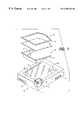
- FIG. 1is an exploded perspective view of a preferred embodiment of an apparatus that incorporates the invention.
- FIG. 2 ais an expanded schematic view of a scan mechanism.
- FIG. 2 bis an expanded view of a first preferred scan mechanism for use with the invention.
- FIG. 2 cis an expanded view of a second preferred scan mechanism for use with the invention.
- FIG. 3illustrates a retro-reflective bead on a compliant sheet.
- FIG. 4is a block diagram of elements of the processor shown in FIG. 1 .
- FIGS. 5 a - 5 dillustrate the operation of the apparatus of FIG. 1, during the process of acquiring contour data of the underside of a foot.
- FIG. 6is a schematic side view of a further embodiment of the invention.
- FIG. 7is a perspective view of an insole that is constructed using data achieved through operation of the invention.
- FIG. 8is a contour illustration of the underside of a foot using data acquired through operation of the invention
- optical scanner 10is configured much the same as a flat plate document scanner.
- optical scanner 10includes a housing 12 and an upper, transparent plate 14 which may be either glass or a polymer/acrylic material.
- An optical scan structure 15is positioned within housing 12 and includes a light source 16 and a linear detector array 18 , both of which are mounted for movement on a pair of rails 20 (only one rail is shown).
- a measure bar 21is positioned on transparent plate 14 and is used to obtain a measure of the length of a foot being imaged.
- Motor meansare present within housing 12 (not shown) and enable the optical scan structure 15 to move beneath transparent plate 14 in substantially the same manner as in prior art document scanners.
- the position of the light sourceis an important consideration in achieving reliable elevation information.
- the light sourcemust provide uniform illumunation from the camera's viewpoint.
- Most commercially available flatbed document scannersuse a light source 16 on one or the other side of an active scanning opening. This yields a light source that is suited to the purpose for which the scanner was designed (namely scanning a flat sheet of paper a known distance from the active scanner opening), but yields a light source that will unevenly light an uneven surface.
- FIG. 2 ashows a measured surface 21 that is more perpendicular to the light source's emitted light and is more efficient at reflecting that light towards the scanner's active scanning element opening 19 . This is aided by addition of a “reflex light source”, as shown in FIG. 2 b.
- FIG. 2 breflects the source light off of a 50% reflective mirror 23 located directly in the active scanning area of the scanner.
- Mirror 23reflects 50% of the source's light directly at surface 21 .
- Light not reflected by mirror 23is sent to light sink 25 , to prevent stray light from interfering with the scanning.
- the embodiment of FIG. 2 bmakes the apparent light location the same as the scanner's location and yields a near perfect lighting configuration.
- a further scanner embodimentis shown in FIG. 2 c and includes a collimated light source 100 whose output beam 102 is passed through a prism 104 which converts light beam 102 into a beam 106 comprising a rainbow of colors.
- Rainbow beam 106is then reflected upwardly by mirror 108 onto the body being imaged. Any contoured item in the projection path of rainbow beam 106 will reflect a color back to color detector 110 that is a function of the distance of the body from reference surface 14 . For instance, if the reflecting surface is positioned at level A, color 112 is reflected along axis 114 to detector 110 . If the reflecting surface is positioned at level B, color 116 is reflected along axis 114 to detector 110 , etc. So long as the field of view of detector 110 is restricted to the immediate region of axis 114 , the other reflected colors are ignored.
- a strip of differing color film and a lenscan be substituted for prism 104 .
- a processor 22receives signals from linear detector array 18 that are indicative of intensities of reflected light from a surface being imaged. The operations of processor 22 will be considered in detail below.
- a slanted support structure 24is positioned on an uppermost surface of housing 12 and is affixed thereto.
- a flange 26extends about the outer periphery of support structure 24 and mates with the outer edges of a compliant sheet 28 that rest thereupon.
- Compliant sheet 28is preferably a flexible sheet of known color and retro-reflectivity.
- a surface that is retro-reflectivehas the property that it sends incident light rays back to the direction from where they came.
- the slope of the reference surface relative to the reference surfacehas little impact in gray scale image data at slope angles of less than 30 degrees. At slope angles in excess of 30 degrees, the flexible sheet is less efficient at reflection. The reduced efficiency is compensated for in software post-processing.
- a preferred method for achieving retro-reflectivityis by embedding glass microspheres 27 into the undersurface of compliant sheet 28 (see FIG. 3 ). Microspheres 27 are adhered to compliant sheet 28 using an elastic coating 29 . Glass microspheres 27 are slighty mirrored and have an index of refraction of approximately 1.5. Ambient incident light 33 that enters a microsphere 27 from off axis angles of over about 60 degrees is rejected and the rest is accepted. The accepted light that enters a microsphere 27 bounces off an interior reflective surface and is emitted at the same angle from whence it came.
- compliant sheet 28need not be continuously coated with microspheres 27 and embedding ink 29 . They need only be applied periodically (as in a dot pattern for instance). This will allow compliant sheet 28 greater flexibility than a continuous coating, as well as offering greater potential lifetime.
- the microspherescan be embedded directly into compliant sheet 28 . This is accomplished during manufacture of the complaint sheet.
- the method of embeddingcan be by heating to slightly melt the surface of compliant sheet 28 and thereafter embedding microspheres 27 therein.
- microspheres 27should be embedded to approximately 1 ⁇ 2 of their diameter, and the sheet into which they are embedded should have a uniform color or reflectivity.
- the compliant sheetneed not have embedded microspheres but should preferably have a highly reflective coloration. Software processing is then needed to compensate for non-linearities in the image data intensity vs. elevation.
- a frame 30sandwiches and seals the outer edges of compliant sheet 28 against flange 26 .
- a series of holes 32are present in transparent plate 14 and enable the attachment of frame 30 , and an underlying edge of compliant sheet 28 directly to transparent plate 14 .
- an air-tight volume 31is created between the lower surface of compliant sheet 28 and the upper surface of transparent plate 14 .
- An air compressor 34is positioned within housing 12 and is coupled, via a tube 36 , to an outlet 38 which leads into air-tight volume 31 .
- Air compressor 34is controlled to maintain a level of pressure within volume 31 such that when a foot, or other object, is placed upon compliant sheet 28 , compliant sheet 28 remains sufficiently flexible to form around the foot/object but is maintained just out of contact with transparent plate 14 .
- FIG. 4the block diagram shown therein illustrates the major components of processor 22 .
- Signals from detector array 18are fed through an analog to digital (A/D) converter 40 and an input/output module 42 and are stored in a memory 44 in the form of pixel/intensity data 46 .
- A/Danalog to digital
- memory 44Also stored within memory 44 is a calibration table 48 which equates intensity levels to distances from a reference or datum surface (e.g., transparent plate 14 or the flat surface defined by a plane resident on flange 26 , FIG. 1 ).
- a reference or datum surfacee.g., transparent plate 14 or the flat surface defined by a plane resident on flange 26 , FIG. 1 .
- Memory 44further includes a contour detection procedure 50 which enables the derivation of contour values from the pixel/intensity data 46 derived during a scan action of optical scan structure 15 .
- contour detection procedure 50in combination with central processing unit (CPU) 52 , operates upon the pixel intensity data 46 and utilizes the distance entries in calibration table 48 to arrive at the contour data.
- CPU 52also issues signals to a motor/light control module 54 which, in turn, controls the operation of light source 16 and the motor which moves optical scan structure 15 beneath transparent plate 14 .
- FIG. 3Aillustrates a cutaway side view of optical scanner 10 , prior to volume 31 having been pressurized by operation of air compressor 34 .
- compliant sheet 28is uninflated and droops into volume 31 of support structure 24 .
- FIG. 3Bwhen air compressor 34 is energized by a signal from CPU 52 , airflow into the volume 31 causes compliant sheet 28 to extend upwardly as a result of a pressure build-up in volume 31 .
- a foot 60is about to be placed on compliant sheet 28 .
- both the heel and the arch of foot 60are positioned directly above the uppermost regions of support structure 24 .
- compliant sheet 28molds itself to the shape of the arch and heel in an enveloping fashion.
- the air pressure within volume 31is maintained at a level that allows the portion of compliant sheet 28 that is immediately below the heel of foot 60 to either just touch or, preferably, be just offset from the upper surface of transparent plate 14 .
- compliant sheet 28molds itself to the bottommost surface of foot 60 and provides a uniformly colored surface for subsequent scanning. Note that the arrangement shown in FIG. 5 d enables the imaging of the heel and arch (behind the metatarsels) as those are the regions of a foot whose dimensions must be known in order to enable the configuration of an orthotic support structure therefor.
- processor 22is instructed to commence a scan action. Accordingly, CPU 52 issues a signal to motor/light control module 54 to commence movement of optical scan structure 15 (FIG. 1 ). Accordingly, light source 16 is energized and projects a beam upwardly onto the undersurface of compliant sheet 28 . The reflections from compliant sheet 28 are sensed by linear detector array 18 , causing analog light intensity signals to be fed to A/D converter 40 , which converts those signals to digital intensity values. Those digital intensity values are then stored in pixel/intensity data region 46 of memory 44 .
- contour detection procedure 50causes each intensity value to be used to address calibration table 48 which, in turn, returns a distance value that is indicative of the distance of the respective pixel position from the datum surface.
- the contour valuescan be used to determine the amount of a conformable material to be injected into a mold to create an orthotic or an insole that matches the underside of the foot.
- the contour valuescan be used to control the machining of a blank to produce an orthotic matched to the underside of a user's foot.
- the light intensity values derived during a scanexhibit a progressively darker value as the distance increases between the scanned surface of compliant sheet 28 and transparent plate 14 . Since the slope of support structure 24 is known, and the change in elevation between successive scan lines is also known, the elevation for any light intensity level observed at any given point can be derived. It is preferred that calibration table 48 be derived initially to enable a table lookup operation to be performed when converting from intensity values to distance values. In addition to the contour data, a sensing of the marking increments on measuring bar 21 during the scanning action enables a length dimension of the foot to be acquired.
- a flat plate(not shown) is placed at an angle relative to the reference surface (e.g., transparent plate 14 ) and air is introduced into interior 31 of support structure 24 .
- Compliant sheet 28is thus forced against the undersurface of the flat plate.
- a gray scale scanis performed of the underside of compliant sheet 28 .
- the digitized imageis processed and saved.
- the area recorded with the slanted flat plane in viewexhibits a progressively darker image as the plane moves further away from the reference surface, (or in the event no reference surface is used), the scanning plane. Since the size of the flat calibration plane is known and the angle at which it was placed relative to the reference surface or scanning plane is known, the elevation for any given intensity can be derived. Those elevation distances are then stored in calibration table 48 , which correlates the distance values to the respective light intensity values which gave rise thereto. Then, when a foot is scanned, the resulting intensity values derived from the underside of compliant sheet 28 are used to address the calibration table 28 , enabling read-out of the corresponding distance values.
- a spherecan be used with a known radius.
- the sphereis placed against compliant sheet 28 such that it is tangent to the reference surface or the scanning plane. Air is then introduced into support structure 24 and the compliant sheet 28 is caused to assume the shape of the sphere. Compliant sheet 28 is scanned and the resulting image analyzed. Each elevation represented by an observed intensity can be readily derived when the radius of the sphere is known.
- contour detection procedure 50performs image processing actions to capture the portion of the image directly related to the foot contour. More particularly, contour detection procedure 50 finds the active areas of the foot in the image by sensing edge pixels which encompass the contour image (e.g., by looking for pixels which, after a run of constant intensity pixels, commence a change of intensity—indicating a boundary between a non-stressed portion of compliant sheet 28 and a stressed portion thereof). The image is then trimmed so that a portion behind the heel is eliminated.
- the heel areais centered in the image area and it is then rotated so that the forefoot is also in the middle of the image area.
- any image areas outside of the image boundaryare trimmed.
- the pixel intensity values within the now-captured foot contour regionare converted to height values by referring the pixel intensity values to calibration table 48 and reading out the respective height data.
- FIG. 6a further embodiment of the invention is illustrated wherein support structure 70 is arranged so that compliant sheet 28 is held parallel to transparent plate 14 . Accordingly, when a foot is thereafter placed on compliant sheet 28 , the sheet stretches and assumes the shape of the foot surface.
- An air supplyis optional in this embodiment, but is preferred so as to enable pressurization of volume 72 so as to enable control of of the amount of deflection of compliant sheet 28 .
- FIG. 7illustrates a three dimensional view of an insole that is configured through use of the foot contour data derived as described above.
- FIG. 8illustrates a contour image that is constructed from the foot contour data. It is preferred that the individual contours be shown in different colors to enable the user to better visualize foot surface differences.
Landscapes
- Health & Medical Sciences (AREA)
- Life Sciences & Earth Sciences (AREA)
- Physics & Mathematics (AREA)
- Heart & Thoracic Surgery (AREA)
- Molecular Biology (AREA)
- Veterinary Medicine (AREA)
- Biophysics (AREA)
- Pathology (AREA)
- Engineering & Computer Science (AREA)
- Biomedical Technology (AREA)
- General Physics & Mathematics (AREA)
- Medical Informatics (AREA)
- Public Health (AREA)
- Surgery (AREA)
- Animal Behavior & Ethology (AREA)
- General Health & Medical Sciences (AREA)
- Radiology & Medical Imaging (AREA)
- Nuclear Medicine, Radiotherapy & Molecular Imaging (AREA)
- Dentistry (AREA)
- Oral & Maxillofacial Surgery (AREA)
- Length Measuring Devices By Optical Means (AREA)
Abstract
Description
This invention relates in general to the precise measurement of a contoured surface and, more specifically, to measurements of the contour of the undersurface of the foot.
Every foot is different and all require proper fitting of footwear in order to maintain good foot health. Measurement of the foot has long been done using length and width measurements. Those measurements yield a fair characterization of the general attributes of the foot, but fail to address the unique shape of the undersurface of the foot.
A number of prior art devices have, with varying degrees of success, measured the undersurface of the foot. Optical scanners that use a laser line optic that is projected onto the underside of a foot and a video camera that records the modified location of the reflected line, produce accurate contours. This technique only works well in a non-weightbearing circumstance. The reason is that the foot increases in length by approximately one size (the width also expands) when weight is applied. Measurement of the foot using such a scanner in a non-weight bearing arrangement will result in a data set that does not allow for this natural expansion of the foot in gait.
U.S. Pat. No. 5,689,446 to Sundman et al. and assigned to the same Assignee as this Application, describes a foot contour digitizer wherein a foot is first placed on an array of gauge pins which are in turn deflected to reflect the contour of the underside of the foot. The gauge pins are urged upward by a diaphragm that is moved by air pressure. The deflected gauge pins are then scanned to derive a data set that defines the foot contour.
While the aforementioned measurement device has the advantage of supporting the foot while measurement takes place, the device is inherently expensive, with its hundreds of gauge pins. Details of the gauge pin structure are found in U.S. Pat. No. 4,876,758 to Rollof and assigned to the same Assignee as is this Application.
Franks, in U.S. Pat. No. 4,858,621 discloses a foot pressure measurement system wherein a transparent flat surface is edge-lighted and supports a pliable material on which is placed a foot to be imaged. When the foot applies pressure to the pliable material, an increase in light intensity results in proportion to the pressure, which is sensed by a scanner. The light intensity variations are converted to foot pressure data.
If one places a foot against a transparent flat surface and uses a laser scanner to measure the contour of the undersurface of the foot, the resultant image reflects a contour with large unnatural flat areas of the foot where the foot contacts the transparent surface. Such a device is described in U.S. Pat. Nos. 5,128,880 and 5,237,520 to White.
White discloses a scanner that is similar to a flat plate document scanner, where the undersurface of the foot is imaged in color and the image data is processed to produce elevation data. The White device uses the principle that surfaces that are further away from the contact surface of the scanner will appear darker in the image data.
A problem with the White device is that there is no way to accurately determine the exact distance from the support surface of portions of the foot, using the data which results from the scanned foot image intensities. The variables which act to vary the intensity data include: variations in skin tone and color, ambient light, whether the subject foot is wearing a sock, and the amount of weight applied to the foot. Further, the lowest foot surfaces are whiter in relation to other areas of the foot due to reduced blood flow. Nevertheless, the White structure does exhibit the advantages of: use of an inexpensive flat bed scanner; providing an accurate perimeter of the foot; and providing enough information to characterize certain portions of the foot, e.g. high, low, or sheet arch height.
Even allowing for the variables discussed above, the intensity information acquired from an optical scanner is the sum of three components:
1. The position of the light source relative to the subject surface.
2. The incident angle of light projected onto the subject surface.
3. The distance of the subject surface from the reference surface.
To measure the contour of an object, such as a human foot, the above three components must be taken into consideration. Other variables must be eliminated, or allowed for, to derive accurate elevation data.
Accordingly, it is an object of the invention to provide an improved system for characterizing the undersurface of a foot.
It is another object of the invention to provide an improved system for characterizing the undersurface of a foot that provides consistent intensity data and enables accurate contour data to be derived.
It is a further object of the invention to provide an improved system for characterizing the undersurface of a foot that provides highly accurate foot contour data and enables the production of custom foot supports in accordance therewith.
The invention includes both a method and apparatus for measuring the shape of a surface of an object, such as a human foot. The apparatus includes a support for holding a compliant sheet of known color and retro-reflectivity. The compliant sheet conforms to the shape of the undersurface of the foot. A scanner scans a light beam along the undersurface of the compliant sheet from a vantage point that is below the compliant sheet. A sensor detects reflected light values from the undersurface of the compliant sheet and feeds corresponding signals to a processor. The processor analyzes the signals and determines distance values to portions of the compliant sheet. The distance values enable a contour to be derived that is representative of the undersurface of the foot.
FIG. 1 is an exploded perspective view of a preferred embodiment of an apparatus that incorporates the invention.
FIG. 2ais an expanded schematic view of a scan mechanism.
FIG. 2bis an expanded view of a first preferred scan mechanism for use with the invention.
FIG. 2cis an expanded view of a second preferred scan mechanism for use with the invention.
FIG. 3 illustrates a retro-reflective bead on a compliant sheet.
FIG. 4 is a block diagram of elements of the processor shown in FIG.1.
FIGS. 5a-5dillustrate the operation of the apparatus of FIG. 1, during the process of acquiring contour data of the underside of a foot.
FIG. 6 is a schematic side view of a further embodiment of the invention.
FIG. 7 is a perspective view of an insole that is constructed using data achieved through operation of the invention.
FIG. 8 is a contour illustration of the underside of a foot using data acquired through operation of the invention
Referring to FIG. 1, anoptical scanner 10 is configured much the same as a flat plate document scanner. In that regard,optical scanner 10 includes ahousing 12 and an upper,transparent plate 14 which may be either glass or a polymer/acrylic material. Anoptical scan structure 15 is positioned withinhousing 12 and includes alight source 16 and alinear detector array 18, both of which are mounted for movement on a pair of rails20 (only one rail is shown). Ameasure bar 21 is positioned ontransparent plate 14 and is used to obtain a measure of the length of a foot being imaged. Motor means are present within housing12 (not shown) and enable theoptical scan structure 15 to move beneathtransparent plate 14 in substantially the same manner as in prior art document scanners.
As indicated above, the position of the light source is an important consideration in achieving reliable elevation information. First, the light source must provide uniform illumunation from the camera's viewpoint. Most commercially available flatbed document scanners use alight source 16 on one or the other side of an active scanning opening. This yields a light source that is suited to the purpose for which the scanner was designed (namely scanning a flat sheet of paper a known distance from the active scanner opening), but yields a light source that will unevenly light an uneven surface.
FIG. 2ashows a measuredsurface 21 that is more perpendicular to the light source's emitted light and is more efficient at reflecting that light towards the scanner's activescanning element opening 19. This is aided by addition of a “reflex light source”, as shown in FIG. 2b.
The arrangement of FIG. 2breflects the source light off of a 50%reflective mirror 23 located directly in the active scanning area of the scanner.Mirror 23 reflects 50% of the source's light directly atsurface 21. Light not reflected bymirror 23 is sent tolight sink 25, to prevent stray light from interfering with the scanning. The embodiment of FIG. 2bmakes the apparent light location the same as the scanner's location and yields a near perfect lighting configuration.
A further scanner embodiment is shown in FIG. 2cand includes a collimatedlight source 100 whoseoutput beam 102 is passed through aprism 104 which convertslight beam 102 into abeam 106 comprising a rainbow of colors.Rainbow beam 106 is then reflected upwardly bymirror 108 onto the body being imaged. Any contoured item in the projection path ofrainbow beam 106 will reflect a color back tocolor detector 110 that is a function of the distance of the body fromreference surface 14. For instance, if the reflecting surface is positioned at level A,color 112 is reflected alongaxis 114 todetector 110. If the reflecting surface is positioned at level B,color 116 is reflected alongaxis 114 todetector 110, etc. So long as the field of view ofdetector 110 is restricted to the immediate region ofaxis 114, the other reflected colors are ignored.
As an alternative design, a strip of differing color film and a lens can be substituted forprism 104.
Returning to FIG. 1, aprocessor 22 receives signals fromlinear detector array 18 that are indicative of intensities of reflected light from a surface being imaged. The operations ofprocessor 22 will be considered in detail below.
Aslanted support structure 24 is positioned on an uppermost surface ofhousing 12 and is affixed thereto. Aflange 26 extends about the outer periphery ofsupport structure 24 and mates with the outer edges of acompliant sheet 28 that rest thereupon.Compliant sheet 28 is preferably a flexible sheet of known color and retro-reflectivity. A surface that is retro-reflective has the property that it sends incident light rays back to the direction from where they came. By incorporating a retro-reflective surface, the slope of the reference surface relative to the reference surface has little impact in gray scale image data at slope angles of less than 30 degrees. At slope angles in excess of 30 degrees, the flexible sheet is less efficient at reflection. The reduced efficiency is compensated for in software post-processing.
A preferred method for achieving retro-reflectivity is by embeddingglass microspheres 27 into the undersurface of compliant sheet28 (see FIG.3).Microspheres 27 are adhered tocompliant sheet 28 using anelastic coating 29.Glass microspheres 27 are slighty mirrored and have an index of refraction of approximately 1.5. Ambient incident light33 that enters amicrosphere 27 from off axis angles of over about 60 degrees is rejected and the rest is accepted. The accepted light that enters amicrosphere 27 bounces off an interior reflective surface and is emitted at the same angle from whence it came.
In an alternative embodiment, the undersurface ofcompliant sheet 28 need not be continuously coated withmicrospheres 27 and embeddingink 29. They need only be applied periodically (as in a dot pattern for instance). This will allowcompliant sheet 28 greater flexibility than a continuous coating, as well as offering greater potential lifetime.
In a further embodiment, the microspheres can be embedded directly intocompliant sheet 28. This is accomplished during manufacture of the complaint sheet. The method of embedding can be by heating to slightly melt the surface ofcompliant sheet 28 and thereafter embeddingmicrospheres 27 therein.
Regardless of the method employed, for optimum retro-reflectivity,microspheres 27 should be embedded to approximately ½ of their diameter, and the sheet into which they are embedded should have a uniform color or reflectivity.
In yet another embodiment, the compliant sheet need not have embedded microspheres but should preferably have a highly reflective coloration. Software processing is then needed to compensate for non-linearities in the image data intensity vs. elevation.
Returning to FIG. 1, aframe 30 sandwiches and seals the outer edges ofcompliant sheet 28 againstflange 26. A series ofholes 32 are present intransparent plate 14 and enable the attachment offrame 30, and an underlying edge ofcompliant sheet 28 directly totransparent plate 14.
Whenframe 30,compliant sheet 28 andsupport structure 24 are assembled on the upper surface ofhousing 12, an air-tight volume 31 is created between the lower surface ofcompliant sheet 28 and the upper surface oftransparent plate 14. Anair compressor 34 is positioned withinhousing 12 and is coupled, via atube 36, to anoutlet 38 which leads into air-tight volume 31.Air compressor 34 is controlled to maintain a level of pressure withinvolume 31 such that when a foot, or other object, is placed uponcompliant sheet 28,compliant sheet 28 remains sufficiently flexible to form around the foot/object but is maintained just out of contact withtransparent plate 14.
Turning now to FIG. 4, the block diagram shown therein illustrates the major components ofprocessor 22. Signals fromdetector array 18 are fed through an analog to digital (A/D)converter 40 and an input/output module 42 and are stored in amemory 44 in the form of pixel/intensity data 46. Also stored withinmemory 44 is a calibration table48 which equates intensity levels to distances from a reference or datum surface (e.g.,transparent plate 14 or the flat surface defined by a plane resident onflange 26, FIG.1).
Referring to FIGS. 5a-5d, the method of the invention will be described. FIG. 3A illustrates a cutaway side view ofoptical scanner 10, prior tovolume 31 having been pressurized by operation ofair compressor 34. At this stage,compliant sheet 28 is uninflated and droops intovolume 31 ofsupport structure 24. As shown in FIG. 3B, whenair compressor 34 is energized by a signal fromCPU 52, airflow into thevolume 31 causescompliant sheet 28 to extend upwardly as a result of a pressure build-up involume 31.
As shown in FIG. 5c, afoot 60 is about to be placed oncompliant sheet 28. Note that both the heel and the arch offoot 60 are positioned directly above the uppermost regions ofsupport structure 24. Thus, whenfoot 60 is in full contact with compliant sheet28 (as shown in FIG. 5d)compliant sheet 28 molds itself to the shape of the arch and heel in an enveloping fashion. The air pressure withinvolume 31 is maintained at a level that allows the portion ofcompliant sheet 28 that is immediately below the heel offoot 60 to either just touch or, preferably, be just offset from the upper surface oftransparent plate 14.
Accordingly,compliant sheet 28 molds itself to the bottommost surface offoot 60 and provides a uniformly colored surface for subsequent scanning. Note that the arrangement shown in FIG. 5denables the imaging of the heel and arch (behind the metatarsels) as those are the regions of a foot whose dimensions must be known in order to enable the configuration of an orthotic support structure therefor.
Oncefoot 60 is in place, as shown in FIG. 5d,processor 22 is instructed to commence a scan action. Accordingly,CPU 52 issues a signal to motor/light control module 54 to commence movement of optical scan structure15 (FIG.1). Accordingly,light source 16 is energized and projects a beam upwardly onto the undersurface ofcompliant sheet 28. The reflections fromcompliant sheet 28 are sensed bylinear detector array 18, causing analog light intensity signals to be fed to A/D converter 40, which converts those signals to digital intensity values. Those digital intensity values are then stored in pixel/intensity data region 46 ofmemory 44.
Once a complete scan has been accomplished,contour detection procedure 50 causes each intensity value to be used to address calibration table48 which, in turn, returns a distance value that is indicative of the distance of the respective pixel position from the datum surface. Once those distance values are accumulated, an accurate contour of the underside offoot 60 has been created which can later be used in constructing an orthotic foot support. For instance, the contour values can be used to determine the amount of a conformable material to be injected into a mold to create an orthotic or an insole that matches the underside of the foot. Further, the contour values can be used to control the machining of a blank to produce an orthotic matched to the underside of a user's foot.
The light intensity values derived during a scan exhibit a progressively darker value as the distance increases between the scanned surface ofcompliant sheet 28 andtransparent plate 14. Since the slope ofsupport structure 24 is known, and the change in elevation between successive scan lines is also known, the elevation for any light intensity level observed at any given point can be derived. It is preferred that calibration table48 be derived initially to enable a table lookup operation to be performed when converting from intensity values to distance values. In addition to the contour data, a sensing of the marking increments on measuringbar 21 during the scanning action enables a length dimension of the foot to be acquired.
To calibrate the system, a flat plate (not shown) is placed at an angle relative to the reference surface (e.g., transparent plate14) and air is introduced intointerior 31 ofsupport structure 24.Compliant sheet 28 is thus forced against the undersurface of the flat plate. Thereafter, a gray scale scan is performed of the underside ofcompliant sheet 28. The digitized image is processed and saved.
The area recorded with the slanted flat plane in view exhibits a progressively darker image as the plane moves further away from the reference surface, (or in the event no reference surface is used), the scanning plane. Since the size of the flat calibration plane is known and the angle at which it was placed relative to the reference surface or scanning plane is known, the elevation for any given intensity can be derived. Those elevation distances are then stored in calibration table48, which correlates the distance values to the respective light intensity values which gave rise thereto. Then, when a foot is scanned, the resulting intensity values derived from the underside ofcompliant sheet 28 are used to address the calibration table28, enabling read-out of the corresponding distance values.
There are other methods that can be used to calibrate the system. Instead of a flat plane, a sphere can be used with a known radius. The sphere is placed againstcompliant sheet 28 such that it is tangent to the reference surface or the scanning plane. Air is then introduced intosupport structure 24 and thecompliant sheet 28 is caused to assume the shape of the sphere.Compliant sheet 28 is scanned and the resulting image analyzed. Each elevation represented by an observed intensity can be readily derived when the radius of the sphere is known.
Once contour image data is acquired,contour detection procedure 50 performs image processing actions to capture the portion of the image directly related to the foot contour. More particularly,contour detection procedure 50 finds the active areas of the foot in the image by sensing edge pixels which encompass the contour image (e.g., by looking for pixels which, after a run of constant intensity pixels, commence a change of intensity—indicating a boundary between a non-stressed portion ofcompliant sheet 28 and a stressed portion thereof). The image is then trimmed so that a portion behind the heel is eliminated.
Thereafter, the heel area is centered in the image area and it is then rotated so that the forefoot is also in the middle of the image area. Next, any image areas outside of the image boundary are trimmed. Thereafter, the pixel intensity values within the now-captured foot contour region are converted to height values by referring the pixel intensity values to calibration table48 and reading out the respective height data.
Turning now to FIG. 6, a further embodiment of the invention is illustrated whereinsupport structure 70 is arranged so thatcompliant sheet 28 is held parallel totransparent plate 14. Accordingly, when a foot is thereafter placed oncompliant sheet 28, the sheet stretches and assumes the shape of the foot surface. An air supply is optional in this embodiment, but is preferred so as to enable pressurization ofvolume 72 so as to enable control of of the amount of deflection ofcompliant sheet 28.
FIG. 7 illustrates a three dimensional view of an insole that is configured through use of the foot contour data derived as described above. FIG. 8 illustrates a contour image that is constructed from the foot contour data. It is preferred that the individual contours be shown in different colors to enable the user to better visualize foot surface differences.
It should be understood that the foregoing description is only illustrative of the invention. Various alternatives and modifications can be devised by those skilled in the art without departing from the invention. Accordingly, the present invention is intended to embrace all such alternatives, modifications and variances which fall within the scope of the appended claims.
Claims (22)
1. A method of measuring the shape of an undersurface of an object, the method comprising the steps of:
a) placing a surface of the object against a compliant sheet so as to cause said compliant sheet to conform to a shape of the surface of the object;
b) scanning the undersurface of the compliant sheet with a light beam, from a vantage point that is below the compliant sheet;
c) sensing reflected light intensities from said undersurface of the compliant sheet during said scanning; and
d) determining distance values to portions of the compliant sheet from measured data derived from said reflected light intensities, said distance values enabling a contour to be derived of said surface of said object.
2. The method as recited in claim1, further comprising the steps of:
i) prior to placement of said object, scanning the undersurface of the compliant sheet with a light beam, from a vantage point that is below the compliant sheet;
ii) sensing reflected light intensities from said undersurface of the compliant sheet during said scanning; and
iii) determining reference distance values to portions of the compliant sheet using said data derived from said reflected light; and
wherein step d) employs said reference distance values and measured data to determine positions of said compliant sheet.
3. The method as recited in claim1, wherein step b) is accomplished by moving a light beam along said undersurface of said compliant sheet, said light beam projected against said compliant sheet from beneath.
4. The method as recited in claim1, wherein step b) is accomplished by moving a light beam evidencing multiple separate colors along said undersurface of said compliant sheet, and step c) senses a particular color of reflected light in accordance with a distance of said compliant sheet from a detector.
5. The method as recited in claim1, wherein said object is a human foot.
6. The method as recited in claim5, comprising the further step of:
determining from said contour, an amount of material to inject into a form to provide an insole for support of the foot.
7. The method as recited in claim5, comprising the further step of:
determining from said contour, an amount of material to inject into a form to provide an orthotic for support of the foot.
8. The method as recited in claim5, comprising the further step of:
determining from said contour, an amount of material to be machined from a blank to provide an insole or an othotic for support of the foot.
9. The method as recited in claim5, comprising the further step of:
determining from said contour, data to enable display of a multi-contour representation of the underside of said foot.
10. The method as recited in claim5, comprising the further step of:
determining from said contour, data to enable display of a three dimensional view of an insole for support of the foot.
11. Apparatus for measuring a shape of a surface of an object, said apparatus comprising:
a) support means for holding a compliant sheet, said compliant sheet responsive to placement of said surface of said object thereagainst to conform to a shape of said surface;
b) scanning means for scanning a light beam along an undersurface of the compliant sheet, said scanning means oriented to project said light beam from a vantage point that is below the undersurface of the compliant sheet;
c) sense means for detecting reflected light from said undersurface of the compliant sheet during said scanning; and
d) processor means responsive to data derived from outputs from said sense means for determining distance values from a datum surface to portions of the compliant sheet, said distance values enabling a contour to be derived that represents said surface of said object.
12. The apparatus as recited in claim11, wherein said support means orients said compliant sheet at an oblique angle with respect to said datum surface, and said scanning means causes said light beam to traverse along a plane parallel to said datum surface.
13. The apparatus as recited in claim11, wherein said support means further comprises;
an enclosed cavity that is substantially air tight; and
means for adjusting air pressure in said enclosed cavity to support said object, while allowing said compliant sheet to form around said object.
14. The apparatus as recited in claim11, wherein said datum surface comprises an optically transparent plate through which said light beam is projected.
15. The apparatus as recited in claim11, wherein said undersurface of said compliant sheet includes a region with retro-reflective means affixed thereto.
16. The apparatus as recited in claim11, wherein said undersurface of said compliant sheet includes a region with retro-reflective spheres affixed thereto.
17. The apparatus as recited in claim11, wherein said scanning means comprises a light source and a reflective means for directing a beam of light from said reflective means in a direction that is generally orthogonal to said datum surface onto said compliant sheet.
18. The apparatus as recited in claim11, wherein said scanning means moves a light beam evidencing multiple separate colors along said undersurface of said compliant sheet, and said sense means senses a particular color of reflected light in accordance with a distance of said compliant sheet therefrom.
19. The apparatus as recited in claim11, wherein said object is a human foot.
20. A method of calibrating a distance measurement using a scanner and a compliant sheet, said method comprising the steps of:
a) orienting the compliant sheet along a plane with respect to a datum surface;
b) activating the scanner to scan an undersurface of the compliant sheet with a light beam;
c) sensing reflected light while scanning the undersurface of the compliant sheet;
d) computing a table which relates distance and a light value by comparing known physical distances between the regions of the compliant sheet and a datum surface, and correspondingly positioned light values measured in step c).
21. The method as recited in claim20, comprising the further steps of:
e) placing a surface of a foot against the compliant sheet of known color so as to cause said compliant sheet to conform to a shape of the surface of the foot;
f) scanning the undersurface of the compliant sheet with said light beam;
c) sensing reflected light from said undersurface of the compliant sheet during said scanning; and
d) determining distance values to portions of the compliant sheet from said table by using measured reflected light intensities to access distance values, said distance values enabling a contour to be derived of said surface of said object.
22. A method for measuring the shape of an undersurface of an object, the method comprising the steps of:
a) conforming a compliant sheet to a shape of the undersurface of said object;
b) scanning an undersurface of the compliant sheet with a beam of energy, from a vantage point that is below the compliant sheet; and
c) employing reflections of said beam of energy from said compliant sheet to determine a contour of said shape of the undersurface of said object.
Priority Applications (1)
| Application Number | Priority Date | Filing Date | Title |
|---|---|---|---|
| US09/191,746US6205230B1 (en) | 1998-11-12 | 1998-11-12 | Optical contour digitizer |
Applications Claiming Priority (1)
| Application Number | Priority Date | Filing Date | Title |
|---|---|---|---|
| US09/191,746US6205230B1 (en) | 1998-11-12 | 1998-11-12 | Optical contour digitizer |
Publications (1)
| Publication Number | Publication Date |
|---|---|
| US6205230B1true US6205230B1 (en) | 2001-03-20 |
Family
ID=22706784
Family Applications (1)
| Application Number | Title | Priority Date | Filing Date |
|---|---|---|---|
| US09/191,746Expired - Fee RelatedUS6205230B1 (en) | 1998-11-12 | 1998-11-12 | Optical contour digitizer |
Country Status (1)
| Country | Link |
|---|---|
| US (1) | US6205230B1 (en) |
Cited By (54)
| Publication number | Priority date | Publication date | Assignee | Title |
|---|---|---|---|---|
| US20030001314A1 (en)* | 1995-08-02 | 2003-01-02 | Lyden Robert M. | Method of making custom insoles and point of purchase display |
| US20030122093A1 (en)* | 2001-12-28 | 2003-07-03 | Applied Materials, Inc. | Optical measurement apparatus |
| WO2003087716A1 (en)* | 2002-04-04 | 2003-10-23 | Amfit, Inc. | Compact optical contour digitizer |
| WO2004002309A1 (en)* | 2002-06-12 | 2004-01-08 | Medavinci Development B.V. | A device and method for checking a diabetic foot |
| US20040111544A1 (en)* | 2002-12-09 | 2004-06-10 | Bennett Dwayne H. | Method and apparatus for driving two identical devices with a single UBS port |
| WO2004113823A2 (en) | 2003-06-18 | 2004-12-29 | Amfit, Inc. | Method and system for capturing and supporting 3-d contour |
| US20050097762A1 (en)* | 2002-06-12 | 2005-05-12 | Biesbrouck Gerardus M. | Device and method for examining a diabetic foot |
| US20060070260A1 (en)* | 2004-09-21 | 2006-04-06 | Cavanagh Peter R | Method for design and manufacture of insoles |
| US20060189909A1 (en)* | 2005-02-24 | 2006-08-24 | Hurley Timothy B | Load relieving wound dressing |
| US20060202682A1 (en)* | 2003-11-20 | 2006-09-14 | Micro-Epsilon Messtechnik Gmbh & Co. Kg | Non-contacting position measuring system |
| US20060247892A1 (en)* | 2005-04-28 | 2006-11-02 | Peterson William E | Method and apparatus for manufacturing custom orthotic footbeds that accommodate the effects of tibial torsion |
| US20060277772A1 (en)* | 2005-05-12 | 2006-12-14 | Pupko Michael M | Alternative method for making foot orthotics |
| US20070055405A1 (en)* | 2005-08-19 | 2007-03-08 | Fred Koelling | Interactive on-demand orthotic vending machine and method of producing orthotic including disc version |
| US20070137295A1 (en)* | 2002-12-13 | 2007-06-21 | Scott Kantro | System and method for measuring plantar foot pressure |
| US20070163147A1 (en)* | 2005-09-21 | 2007-07-19 | Cavanagh Peter R | Method for Design and Manufacture of Insoles |
| US20090076772A1 (en)* | 2007-09-18 | 2009-03-19 | Esoles, Llc | Footbeds and a Method and Apparatus for Producing Such Footbeds |
| US20090071019A1 (en)* | 2002-10-17 | 2009-03-19 | Pupko Michael M | Ski boots and other shoes and method for improved balance |
| US20090138234A1 (en)* | 2007-11-07 | 2009-05-28 | Amfit, Inc. | Impression foam digital scanner |
| US20090183390A1 (en)* | 2008-01-17 | 2009-07-23 | Tensegrity Technologies, Inc. | Foot Orthotic Devices |
| EP1980224A3 (en)* | 2007-04-11 | 2009-12-09 | Hanger Orthopedic Group, Inc. | System and method for evalutating the needs of a person and manufacturing a custom orthotic device |
| WO2010007200A1 (en)* | 2008-07-16 | 2010-01-21 | Podo Activa, S.L. | Method and device for obtaining a plantar image and double-sided machining of the insole thus obtained |
| US20100058855A1 (en)* | 2006-10-20 | 2010-03-11 | Amfit, Inc. | Method for determining mobility of regions of an object |
| ES2336533A1 (en)* | 2008-07-16 | 2010-04-13 | Podo Activa, S.L. | Process and device of captation of the image planting through means of subjection and tension of an elastic membrane, as well as the double-sided machining of the template obtained in such process (Machine-translation by Google Translate, not legally binding) |
| US20100130830A1 (en)* | 2008-11-24 | 2010-05-27 | Wei-Cheng Lin | Foot examination and measurement system and method of the same |
| ITAR20090032A1 (en)* | 2009-08-07 | 2011-02-08 | Guantificio Altotiberino Ecosanit C Alz Di Manent | PORTABLE DEVICE FOR FOOT SCANNING, PARTICULARLY FOR THE SHAPE OF THE PLAN OF A HUMAN FOOT, OF AN IMPRESSION ON PHENOLIC FOAM OR ON PLASTILINE AND SIMILAR |
| EP2311343A1 (en)* | 2009-10-07 | 2011-04-20 | Christian Schindlegger | Device for recording the footstep of a person |
| ES2364730A1 (en)* | 2009-07-10 | 2011-09-13 | Podo Activa, S.L | Improvements introduced in the patent p 200802122 "process and device of captation of the planting image through means of subjection and tension of an elastic membrane, as well as the double-sided machining of the template obtained in such process" (Machine-translation by Google Translate, not legally binding) |
| US20120010730A1 (en)* | 2004-05-28 | 2012-01-12 | Christophe Guy Lecomte | Foot prosthesis with resilient multi-axial ankle |
| WO2012030373A1 (en)* | 2010-08-31 | 2012-03-08 | Northwest Podiatric Laboratory, Inc. | Apparatus and method for imaging feet |
| WO2013113769A1 (en)* | 2012-01-30 | 2013-08-08 | Lion Systems S.A. | Method and device for evaluating a contact area between a foot and a surface |
| US20140182152A1 (en)* | 2011-07-25 | 2014-07-03 | Chris Towns | Footgauge |
| US20140276094A1 (en)* | 2013-03-15 | 2014-09-18 | Roy Herman Lidtke | Apparatus for optical scanning of the foot for orthosis |
| US20140378277A1 (en)* | 2012-02-07 | 2014-12-25 | Krullaards Technology B.V. | Device for rebalancing the pelvis and training method associated therewith |
| US8961618B2 (en) | 2011-12-29 | 2015-02-24 | össur hf | Prosthetic foot with resilient heel |
| US9019359B2 (en) | 2012-03-29 | 2015-04-28 | Nike, Inc. | Foot imaging and measurement apparatus |
| WO2015176183A1 (en)* | 2014-05-21 | 2015-11-26 | Cryos Technologies Inc. | Three-dimensional plantar imaging apparatus and membrane assembly for use in the same |
| US20170007160A1 (en)* | 2015-07-07 | 2017-01-12 | Sue Ann Latterman | Methods and systems for sizing an orthotic device |
| USD795433S1 (en) | 2015-06-30 | 2017-08-22 | Össur Iceland Ehf | Prosthetic foot cover |
| USD797292S1 (en) | 2014-06-30 | 2017-09-12 | össur hf | Prosthetic foot plate |
| US9778027B1 (en) | 2010-09-30 | 2017-10-03 | Northwest Podiatric Laboratory, Inc. | Apparatus and method for imaging feet |
| WO2017177304A1 (en)* | 2016-04-13 | 2017-10-19 | Cryos Technologies Inc. | Membrane-based foot imaging apparatus including a camera for monitoring foot positioning |
| US20170360298A1 (en)* | 2016-04-26 | 2017-12-21 | Cryos Technologies Inc. | Three-dimensional plantar imaging apparatus and membrane assembly for use in the same |
| US9901298B2 (en) | 2012-11-01 | 2018-02-27 | Quaerimus Medical Incorporated | System and method for prevention of diabetic foot ulcers using total internal reflection imaging |
| US9955900B2 (en) | 2012-10-31 | 2018-05-01 | Quaerimus, Inc. | System and method for continuous monitoring of a human foot |
| US20180343981A1 (en)* | 2013-03-14 | 2018-12-06 | Modern Protective Footwear, Llc | Protective Patient Footwear System and Methods |
| US10239259B2 (en)* | 2017-07-18 | 2019-03-26 | Ivan Ordaz | Custom insole |
| US10463257B2 (en)* | 2016-03-30 | 2019-11-05 | Aetrex Worldwide, Inc. | System and method for identifying physical properties of feet |
| USD915596S1 (en) | 2018-04-10 | 2021-04-06 | Össur Iceland Ehf | Prosthetic foot with tapered fasteners |
| CN112996408A (en)* | 2019-10-02 | 2021-06-18 | 奥利弗·帕佩 | Optical foot sole scanning device and insole production device with optical foot sole scanning device, method for determining three-dimensional shape of insole, and method for automatically producing insole |
| USRE48771E1 (en) | 2010-08-31 | 2021-10-12 | Northwest Podiatrie Laboratory, Inc. | Apparatus and method for imaging feet |
| US11659112B1 (en) | 2021-12-06 | 2023-05-23 | Teco Image Systems Co., Ltd. | Scanner and load bearing structure thereof |
| JP2023084036A (en)* | 2021-12-06 | 2023-06-16 | 東友科技股▲ふん▼有限公司 | Scanner and its load-bearing structure |
| CN118687479A (en)* | 2024-06-05 | 2024-09-24 | 山东泰开精密铸造有限公司 | A device for measuring the dimensions of aluminum alloy castings |
| US12201537B2 (en) | 2020-11-30 | 2025-01-21 | Össur Iceland Ehf | Prosthetic foot with layers of fibrous material |
Citations (3)
| Publication number | Priority date | Publication date | Assignee | Title |
|---|---|---|---|---|
| US4858621A (en) | 1988-03-16 | 1989-08-22 | Biokinetics, Inc. | Foot pressure measurement system |
| US5128880A (en) | 1990-05-11 | 1992-07-07 | Foot Image Technology, Inc. | Foot measurement and footwear sizing system |
| US5237520A (en) | 1990-05-11 | 1993-08-17 | Foot Image Technology, Inc. | Foot measurement and footwear sizing system |
- 1998
- 1998-11-12USUS09/191,746patent/US6205230B1/ennot_activeExpired - Fee Related
Patent Citations (3)
| Publication number | Priority date | Publication date | Assignee | Title |
|---|---|---|---|---|
| US4858621A (en) | 1988-03-16 | 1989-08-22 | Biokinetics, Inc. | Foot pressure measurement system |
| US5128880A (en) | 1990-05-11 | 1992-07-07 | Foot Image Technology, Inc. | Foot measurement and footwear sizing system |
| US5237520A (en) | 1990-05-11 | 1993-08-17 | Foot Image Technology, Inc. | Foot measurement and footwear sizing system |
Cited By (101)
| Publication number | Priority date | Publication date | Assignee | Title |
|---|---|---|---|---|
| US6939502B2 (en) | 1995-08-02 | 2005-09-06 | Robert M. Lyden | Method of making custom insoles and point of purchase display |
| US20030001314A1 (en)* | 1995-08-02 | 2003-01-02 | Lyden Robert M. | Method of making custom insoles and point of purchase display |
| US20030122093A1 (en)* | 2001-12-28 | 2003-07-03 | Applied Materials, Inc. | Optical measurement apparatus |
| US7112812B2 (en) | 2001-12-28 | 2006-09-26 | Applied Materials, Inc. | Optical measurement apparatus |
| US20060227337A1 (en)* | 2002-04-04 | 2006-10-12 | Amfit, Inc. | Compact optical contour digitizer |
| WO2003087716A1 (en)* | 2002-04-04 | 2003-10-23 | Amfit, Inc. | Compact optical contour digitizer |
| EP1490651A4 (en)* | 2002-04-04 | 2007-02-14 | Amfit Inc | Compact optical contour digitizer |
| US7952727B2 (en) | 2002-04-04 | 2011-05-31 | Amfit, Inc. | Compact optical contour digitizer |
| US20030212506A1 (en)* | 2002-04-04 | 2003-11-13 | Amfit, Inc. | Compact optical contour digitizer |
| US7068379B2 (en)* | 2002-04-04 | 2006-06-27 | Amfit, Inc. | Compact optical contour digitizer |
| US20050097762A1 (en)* | 2002-06-12 | 2005-05-12 | Biesbrouck Gerardus M. | Device and method for examining a diabetic foot |
| WO2004002309A1 (en)* | 2002-06-12 | 2004-01-08 | Medavinci Development B.V. | A device and method for checking a diabetic foot |
| NL1020839C2 (en)* | 2002-06-12 | 2004-01-08 | Medavinci Dev B V | Device and method for checking a diabetic foot. |
| US9078494B2 (en) | 2002-10-17 | 2015-07-14 | Michael M. Pupko | Ski boots and other shoes and method for improved balance |
| US20090071019A1 (en)* | 2002-10-17 | 2009-03-19 | Pupko Michael M | Ski boots and other shoes and method for improved balance |
| US20040111544A1 (en)* | 2002-12-09 | 2004-06-10 | Bennett Dwayne H. | Method and apparatus for driving two identical devices with a single UBS port |
| US20070137295A1 (en)* | 2002-12-13 | 2007-06-21 | Scott Kantro | System and method for measuring plantar foot pressure |
| US7337680B2 (en)* | 2002-12-13 | 2008-03-04 | Scott Kantro | System and method for measuring plantar foot pressure |
| EP1639311A4 (en)* | 2003-06-18 | 2006-10-25 | Amfit Inc | Method and system for capturing and supporting 3-d contour |
| WO2004113823A2 (en) | 2003-06-18 | 2004-12-29 | Amfit, Inc. | Method and system for capturing and supporting 3-d contour |
| CN100368763C (en)* | 2003-06-18 | 2008-02-13 | 阿莫菲特公司 | Method and system for capturing and supporting 3D contours |
| US20060202682A1 (en)* | 2003-11-20 | 2006-09-14 | Micro-Epsilon Messtechnik Gmbh & Co. Kg | Non-contacting position measuring system |
| US7602175B2 (en)* | 2003-11-20 | 2009-10-13 | Micro-Epsilon Messtechnik Gmbh & Co. Kg | Non-contacting position measuring system |
| US9668887B2 (en) | 2004-05-28 | 2017-06-06 | össur hf | Foot prosthesis with resilient multi-axial ankle |
| US9132022B2 (en)* | 2004-05-28 | 2015-09-15 | össur hf | Foot prosthesis with resilient multi-axial ankle |
| US20120010730A1 (en)* | 2004-05-28 | 2012-01-12 | Christophe Guy Lecomte | Foot prosthesis with resilient multi-axial ankle |
| US7206718B2 (en)* | 2004-09-21 | 2007-04-17 | Diapedic, L.L.C. | Method for design and manufacture of insoles |
| WO2006034261A3 (en)* | 2004-09-21 | 2006-12-14 | Diapedia L L C | Method for design and manufacture of insoles |
| US20060070260A1 (en)* | 2004-09-21 | 2006-04-06 | Cavanagh Peter R | Method for design and manufacture of insoles |
| US20060189909A1 (en)* | 2005-02-24 | 2006-08-24 | Hurley Timothy B | Load relieving wound dressing |
| US7552494B2 (en) | 2005-04-28 | 2009-06-30 | Esoles, L.L.C. | Method and apparatus for manufacturing custom orthotic footbeds that accommodate the effects of tibial torsion |
| US20060247892A1 (en)* | 2005-04-28 | 2006-11-02 | Peterson William E | Method and apparatus for manufacturing custom orthotic footbeds that accommodate the effects of tibial torsion |
| US20060277772A1 (en)* | 2005-05-12 | 2006-12-14 | Pupko Michael M | Alternative method for making foot orthotics |
| US20070055405A1 (en)* | 2005-08-19 | 2007-03-08 | Fred Koelling | Interactive on-demand orthotic vending machine and method of producing orthotic including disc version |
| US8170705B2 (en) | 2005-08-19 | 2012-05-01 | Alipes, Inc. | Interactive on-demand orthotic vending machine and method of producing orthotic including disc version |
| US20070163147A1 (en)* | 2005-09-21 | 2007-07-19 | Cavanagh Peter R | Method for Design and Manufacture of Insoles |
| US8290739B2 (en)* | 2006-10-20 | 2012-10-16 | Amfit, Inc. | Method for determining relative mobility of regions of an object |
| US20100058855A1 (en)* | 2006-10-20 | 2010-03-11 | Amfit, Inc. | Method for determining mobility of regions of an object |
| EP1980224A3 (en)* | 2007-04-11 | 2009-12-09 | Hanger Orthopedic Group, Inc. | System and method for evalutating the needs of a person and manufacturing a custom orthotic device |
| US20090076772A1 (en)* | 2007-09-18 | 2009-03-19 | Esoles, Llc | Footbeds and a Method and Apparatus for Producing Such Footbeds |
| US7895009B2 (en) | 2007-11-07 | 2011-02-22 | Amfit, Inc. | Impression foam digital scanner |
| US20090138234A1 (en)* | 2007-11-07 | 2009-05-28 | Amfit, Inc. | Impression foam digital scanner |
| EP2208169A4 (en)* | 2007-11-07 | 2013-06-05 | Amfit Inc | Impression foam digital scanner |
| US8109014B2 (en) | 2008-01-17 | 2012-02-07 | Tensegrity Technologies, Inc. | Foot orthotic devices |
| US7926363B2 (en) | 2008-01-17 | 2011-04-19 | Tensegrity Technologies, Inc. | Systems for designing a foot orthotic |
| US20090183390A1 (en)* | 2008-01-17 | 2009-07-23 | Tensegrity Technologies, Inc. | Foot Orthotic Devices |
| US8596145B2 (en) | 2008-01-17 | 2013-12-03 | Tensegrity Technologies, Inc. | Systems for designing a foot orthotic |
| US20110162238A1 (en)* | 2008-01-17 | 2011-07-07 | Tensegrity Technologies, Inc. | Systems for designing a foot orthotic |
| CN102159135B (en)* | 2008-07-16 | 2013-10-23 | 派德-爱克发有限公司 | Method and device for obtaining plantar image and double-sided machining of insole thus obtained |
| WO2010007200A1 (en)* | 2008-07-16 | 2010-01-21 | Podo Activa, S.L. | Method and device for obtaining a plantar image and double-sided machining of the insole thus obtained |
| EP2314219A4 (en)* | 2008-07-16 | 2013-04-03 | Podo Activa S L | METHOD AND DEVICE FOR CAPTURING PLANAR IMAGE AND DOUBLE-SIDED MACHINING OF SOLE OBTAINED ACCORDING TO SAID METHOD |
| CN102159135A (en)* | 2008-07-16 | 2011-08-17 | 派德-爱克发有限公司 | Method and device for |
| ES2336533B1 (en)* | 2008-07-16 | 2011-05-11 | Podo Activa, S.L. | PROCESS AND DEVICE FOR THE CAPTURE OF THE PLANTAR IMAGE THROUGH MEANS OF TIGHTENING AND TENSION OF AN ELASTIC MEMBRANE, AS WELL AS THE DOUBLE-SIDED MACHINING OF THE TEMPLATE OBTAINED IN THIS PROCESS. |
| ES2336533A1 (en)* | 2008-07-16 | 2010-04-13 | Podo Activa, S.L. | Process and device of captation of the image planting through means of subjection and tension of an elastic membrane, as well as the double-sided machining of the template obtained in such process (Machine-translation by Google Translate, not legally binding) |
| US9179741B2 (en) | 2008-07-16 | 2015-11-10 | Podo Activa, S.L. | Method and device for obtaining a plantar image and double-sided machining of the insole thus obtained |
| US20100130830A1 (en)* | 2008-11-24 | 2010-05-27 | Wei-Cheng Lin | Foot examination and measurement system and method of the same |
| ES2364730A1 (en)* | 2009-07-10 | 2011-09-13 | Podo Activa, S.L | Improvements introduced in the patent p 200802122 "process and device of captation of the planting image through means of subjection and tension of an elastic membrane, as well as the double-sided machining of the template obtained in such process" (Machine-translation by Google Translate, not legally binding) |
| ITAR20090032A1 (en)* | 2009-08-07 | 2011-02-08 | Guantificio Altotiberino Ecosanit C Alz Di Manent | PORTABLE DEVICE FOR FOOT SCANNING, PARTICULARLY FOR THE SHAPE OF THE PLAN OF A HUMAN FOOT, OF AN IMPRESSION ON PHENOLIC FOAM OR ON PLASTILINE AND SIMILAR |
| EP2311343A1 (en)* | 2009-10-07 | 2011-04-20 | Christian Schindlegger | Device for recording the footstep of a person |
| WO2012030373A1 (en)* | 2010-08-31 | 2012-03-08 | Northwest Podiatric Laboratory, Inc. | Apparatus and method for imaging feet |
| US9194696B2 (en) | 2010-08-31 | 2015-11-24 | Northwest Podiatric Laboratory, Inc. | Apparatus and method for imaging feet |
| USRE48771E1 (en) | 2010-08-31 | 2021-10-12 | Northwest Podiatrie Laboratory, Inc. | Apparatus and method for imaging feet |
| US8567081B2 (en) | 2010-08-31 | 2013-10-29 | Northwest Podiatric Laboratory, Inc. | Apparatus and method for imaging feet |
| US9778027B1 (en) | 2010-09-30 | 2017-10-03 | Northwest Podiatric Laboratory, Inc. | Apparatus and method for imaging feet |
| US9380835B2 (en)* | 2011-07-25 | 2016-07-05 | C. & J. Clark International Limited | Footgauge |
| US20140182152A1 (en)* | 2011-07-25 | 2014-07-03 | Chris Towns | Footgauge |
| US8961618B2 (en) | 2011-12-29 | 2015-02-24 | össur hf | Prosthetic foot with resilient heel |
| WO2013113769A1 (en)* | 2012-01-30 | 2013-08-08 | Lion Systems S.A. | Method and device for evaluating a contact area between a foot and a surface |
| US20140378277A1 (en)* | 2012-02-07 | 2014-12-25 | Krullaards Technology B.V. | Device for rebalancing the pelvis and training method associated therewith |
| US9019359B2 (en) | 2012-03-29 | 2015-04-28 | Nike, Inc. | Foot imaging and measurement apparatus |
| US9955900B2 (en) | 2012-10-31 | 2018-05-01 | Quaerimus, Inc. | System and method for continuous monitoring of a human foot |
| US9901298B2 (en) | 2012-11-01 | 2018-02-27 | Quaerimus Medical Incorporated | System and method for prevention of diabetic foot ulcers using total internal reflection imaging |
| US10575596B2 (en)* | 2013-03-14 | 2020-03-03 | Modern Protective Footwear, Llc | Protective patient footwear system and methods |
| US20180343981A1 (en)* | 2013-03-14 | 2018-12-06 | Modern Protective Footwear, Llc | Protective Patient Footwear System and Methods |
| WO2014144052A3 (en)* | 2013-03-15 | 2014-11-06 | Ortho Research, Llc | Apparatus for optical scanning of the foot for orthosis |
| US20140276094A1 (en)* | 2013-03-15 | 2014-09-18 | Roy Herman Lidtke | Apparatus for optical scanning of the foot for orthosis |
| WO2015176183A1 (en)* | 2014-05-21 | 2015-11-26 | Cryos Technologies Inc. | Three-dimensional plantar imaging apparatus and membrane assembly for use in the same |
| US9757035B2 (en)* | 2014-05-21 | 2017-09-12 | Cryos Technologies Inc | Three-dimensional plantar imaging apparatus and membrane assembly for use in the same |
| US20160249807A1 (en)* | 2014-05-21 | 2016-09-01 | Cryos Technologies Inc. | Three-dimensional plantar imaging apparatus and membrane assembly for use in the same |
| US11147692B2 (en) | 2014-06-30 | 2021-10-19 | Össur Iceland Ehf | Prosthetic feet and foot covers |
| USD797292S1 (en) | 2014-06-30 | 2017-09-12 | össur hf | Prosthetic foot plate |
| US9999524B2 (en) | 2014-06-30 | 2018-06-19 | össur hf | Prosthetic feet and foot covers |
| USD795433S1 (en) | 2015-06-30 | 2017-08-22 | Össur Iceland Ehf | Prosthetic foot cover |
| US10149637B2 (en)* | 2015-07-07 | 2018-12-11 | Sue Ann Latterman | Methods and systems for sizing an orthotic device |
| US20170007160A1 (en)* | 2015-07-07 | 2017-01-12 | Sue Ann Latterman | Methods and systems for sizing an orthotic device |
| US10463257B2 (en)* | 2016-03-30 | 2019-11-05 | Aetrex Worldwide, Inc. | System and method for identifying physical properties of feet |
| US20190209093A1 (en)* | 2016-04-13 | 2019-07-11 | Cryos Technologes Inc. | Membrane-based foot imaging apparatus including a camera for monitoring foot positioning |
| US12011298B2 (en)* | 2016-04-13 | 2024-06-18 | Cryos Technologes Inc. | Membrane-based foot imaging apparatus including a camera for monitoring foot positioning |
| WO2017177304A1 (en)* | 2016-04-13 | 2017-10-19 | Cryos Technologies Inc. | Membrane-based foot imaging apparatus including a camera for monitoring foot positioning |
| AU2016402993B2 (en)* | 2016-04-13 | 2021-11-18 | Cryos Technologies Inc. | Membrane-based foot imaging apparatus including a camera for monitoring foot positioning |
| US20170360298A1 (en)* | 2016-04-26 | 2017-12-21 | Cryos Technologies Inc. | Three-dimensional plantar imaging apparatus and membrane assembly for use in the same |
| US10239259B2 (en)* | 2017-07-18 | 2019-03-26 | Ivan Ordaz | Custom insole |
| USD915596S1 (en) | 2018-04-10 | 2021-04-06 | Össur Iceland Ehf | Prosthetic foot with tapered fasteners |
| CN112996408A (en)* | 2019-10-02 | 2021-06-18 | 奥利弗·帕佩 | Optical foot sole scanning device and insole production device with optical foot sole scanning device, method for determining three-dimensional shape of insole, and method for automatically producing insole |
| US20230270211A1 (en)* | 2019-10-02 | 2023-08-31 | Oliver Pape | Optical Foot Sole Scanning Apparatus and Insole Production Apparatus Having Same, Method for Ascertaining a Three-Dimensional Shape of an Insole and Method for Automatically Producing an Insole |
| CN112996408B (en)* | 2019-10-02 | 2022-06-14 | 奥利弗·帕佩 | Foot scanning system, method for determining three-dimensional shape of insole and method for producing insole |
| US12239190B2 (en)* | 2019-10-02 | 2025-03-04 | Oliver Pape | Optical foot sole scanning apparatus and insole production apparatus having same, method for ascertaining a three-dimensional shape of an insole and method for automatically producing an insole |
| US12201537B2 (en) | 2020-11-30 | 2025-01-21 | Össur Iceland Ehf | Prosthetic foot with layers of fibrous material |
| US11659112B1 (en) | 2021-12-06 | 2023-05-23 | Teco Image Systems Co., Ltd. | Scanner and load bearing structure thereof |
| JP2023084036A (en)* | 2021-12-06 | 2023-06-16 | 東友科技股▲ふん▼有限公司 | Scanner and its load-bearing structure |
| CN118687479A (en)* | 2024-06-05 | 2024-09-24 | 山东泰开精密铸造有限公司 | A device for measuring the dimensions of aluminum alloy castings |
Similar Documents
| Publication | Publication Date | Title |
|---|---|---|
| US6205230B1 (en) | Optical contour digitizer | |
| US7952727B2 (en) | Compact optical contour digitizer | |
| US7227648B2 (en) | Method and apparatus for a touch-free examination of objects, particularly regarding the surface character of the same | |
| US5753931A (en) | Object imaging device and method using line striping | |
| US5689446A (en) | Foot contour digitizer | |
| US5602379A (en) | Optical code reader | |
| CA1235226A (en) | Electronic foot measuring apparatus and method | |
| US20100008543A1 (en) | Shape measuring device and shape measuring method | |
| JP4121576B2 (en) | Lens parameter measuring method and measuring apparatus using optical section | |
| US5889582A (en) | Image-directed active range finding system | |
| US6856935B1 (en) | Camera tracking system for a virtual television or video studio | |
| JP2002527832A (en) | Fingerprint image optical input device | |
| JPH1065882A (en) | Method for acquiring medium surface shape data | |
| JPH0242307A (en) | Apparatus and method for displaying surface contour of convex object | |
| US20020171826A1 (en) | Multi-beam apparatus for measuring surface quality | |
| CN113375583A (en) | Light path system, monocular three-dimensional image acquisition system and three-dimensional strain detection system | |
| US7895009B2 (en) | Impression foam digital scanner | |
| US7456941B2 (en) | Measuring device for measuring the refraction properties of optical lenses | |
| JP3211835B2 (en) | Apparatus and method for evaluating skin wrinkles in vivo | |
| US7453558B2 (en) | Measuring device for measuring the refraction properties of optical lenses | |
| NL1020394C2 (en) | Device for digitizing curved and flat surfaces. | |
| US20130162816A1 (en) | Device for measuring the shape of a mirror or of a specular surface | |
| JPH1114327A (en) | Three-dimensional shape measuring method and device therefor | |
| JPH08145639A (en) | Skin surface three-dimensional shape measuring device | |
| US6515771B1 (en) | Image reading apparatus having a reference image and measurement means for measuring distortion based on reading the reference image |
Legal Events
| Date | Code | Title | Description |
|---|---|---|---|
| AS | Assignment | Owner name:AMFIT, INC., CALIFORNIA Free format text:ASSIGNMENT OF ASSIGNORS INTEREST;ASSIGNORS:SUNDMAN, ARJEN;WALKER, JAMES T.;REEL/FRAME:009599/0411 Effective date:19981021 | |
| FPAY | Fee payment | Year of fee payment:4 | |
| FPAY | Fee payment | Year of fee payment:8 | |
| REMI | Maintenance fee reminder mailed | ||
| LAPS | Lapse for failure to pay maintenance fees | ||
| STCH | Information on status: patent discontinuation | Free format text:PATENT EXPIRED DUE TO NONPAYMENT OF MAINTENANCE FEES UNDER 37 CFR 1.362 | |
| FP | Lapsed due to failure to pay maintenance fee | Effective date:20130320 | |
| AS | Assignment | Owner name:CONFORMA LC, UTAH Free format text:ASSIGNMENT OF ASSIGNORS INTEREST;ASSIGNOR:AMFIT, INC.;REEL/FRAME:066443/0543 Effective date:20230721 | |
| AS | Assignment | Owner name:AMFIT, LLC, UTAH Free format text:CHANGE OF NAME;ASSIGNOR:CONFORMA, L.C.;REEL/FRAME:066582/0587 Effective date:20230725 |