US6204810B1 - Communications system - Google Patents
Communications systemDownload PDFInfo
- Publication number
- US6204810B1 US6204810B1US08/853,833US85383397AUS6204810B1US 6204810 B1US6204810 B1US 6204810B1US 85383397 AUS85383397 AUS 85383397AUS 6204810 B1US6204810 B1US 6204810B1
- Authority
- US
- United States
- Prior art keywords
- information channel
- information
- rotation
- frequency
- propagation axis
- Prior art date
- Legal status (The legal status is an assumption and is not a legal conclusion. Google has not performed a legal analysis and makes no representation as to the accuracy of the status listed.)
- Expired - Fee Related
Links
Images


Classifications
- H—ELECTRICITY
- H04—ELECTRIC COMMUNICATION TECHNIQUE
- H04B—TRANSMISSION
- H04B10/00—Transmission systems employing electromagnetic waves other than radio-waves, e.g. infrared, visible or ultraviolet light, or employing corpuscular radiation, e.g. quantum communication
- H04B10/50—Transmitters
- H04B10/516—Details of coding or modulation
- H04B10/532—Polarisation modulation
- H—ELECTRICITY
- H04—ELECTRIC COMMUNICATION TECHNIQUE
- H04B—TRANSMISSION
- H04B14/00—Transmission systems not characterised by the medium used for transmission
- H04B14/002—Transmission systems not characterised by the medium used for transmission characterised by the use of a carrier modulation
- H04B14/008—Polarisation modulation
- H—ELECTRICITY
- H04—ELECTRIC COMMUNICATION TECHNIQUE
- H04B—TRANSMISSION
- H04B7/00—Radio transmission systems, i.e. using radiation field
- H04B7/02—Diversity systems; Multi-antenna system, i.e. transmission or reception using multiple antennas
- H04B7/10—Polarisation diversity; Directional diversity
Definitions
- the present inventionrelates generally to communications systems. More specifically, the present invention relates to a communication system in which an information-modulated electromagnetic wave has a carrier frequency and an electric field corresponding to a rotation vector tracing a nonlinear periodic path at a second frequency that is less than the carrier frequency of the wave.
- An electromagnetic wavecan be defined by an electric field and a magnetic field that are orthogonal to one another along an axis of propagation.
- the behavior of the wavecan be described with respect to the orientation of the field vector of the electric (E) field.
- Polarizationis a term that can be used to characterize the orientation of the field vector of an E field of some electromagnetic waves.
- Different types of polarizationinclude: linear (also referred to as plane), circular, and elliptic polarization.
- the polarization of the wavecan be referred to as linear or plane polarization.
- the terminus of the E fieldi.e., the extremity of the field vector, traces a circular helix of period equal to the wavelength of the wave
- the polarizationcan be referred to as circular polarization.
- the terminus of the E fieldforms an elliptical helix of period equal to the wavelength of the wave
- the polarizationcan be referred to as elliptical polarization.
- Polarized wavescan be transmitted or received in a number of different ways.
- an antennaitself can impose a certain polarization upon a transmitted wave or be sensitive to received waves of a certain polarization.
- a dipole antenna oriented horizontally with respect to the earthcan receive and/or transmit linearly polarized waves where the plane of polarization is parallel to the earth.
- a dipole antenna oriented vertically with respect to the earthcan receive and/or transmit linearly polarized waves where the plane of polarization is perpendicular to the earth's surface.
- a helical antennacan receive and/or transmit circularly polarized waves.
- Communications systems transmitting and receiving polarized wavescan be adversely affected by apparent prolonged fading of transmitted/received waves having only one type of polarization.
- communication systemscan simultaneously transmit and receive multiple waves each having a different polarization. This method can be characterized as polarization diversity.
- Polarizationhas also been used to avoid inter-channel interference in geosynchronous satellite communications systems.
- a geosynchronous satellitecan communicate with a ground station using right-hand circular polarized waves at a given carrier frequency, while an adjacent satellite can communicate with another ground station at the same carrier frequency using left-hand circular polarized wave.
- Helical antennas having opposite twistscan be used to receive and/or transmit left-hand and right-hand circular polarized waves.
- Polarizationcan be used to encode information in a communications system.
- U.S. Pat. No. 4,084,137, issued to Weltidescribes a communications system that encodes a horizontally polarized wave and a vertically polarized wave in accordance with information.
- U.S. Statutory Invention Registration H484describes a similar system that addresses a sidelobe problem in a radar system.
- U.S. Pat. No. 5,592,177issued to Barrett, describes a communications system that sequentially changes the polarization of a signal-carrying wave in a pseudorandom manner.
- the Barrett systemprovides broad polarization bandwidth for transmitting and/or receiving signals while minimizing the required frequency bandwidth of the transmitter and receiver systems.
- the selected polarizationsinclude linear polarization with a variable polarization plane orientation, right-hand and left-hand circular polarizations, and right-hand and left-hand elliptical polarizations with a variable ellipse major axis orientation.
- the signalis spread in polarization in a manner analogous to the spreading of a signal over a continuous range of frequencies in spread spectrum communications systems. Note that when the signal-carrying wave is circularly or elliptically polarized, the field vector of the E field is rotating a frequency equal to the carrier frequency.
- the selectivity of the present inventionresults in lower noise and therefore creates a higher signal-to-noise ratio for an information channel.
- the present inventioncan provide an information channel with lower noise.
- the present inventionrelates to a communications system in which a communications channel is defined at least in part by a wave having a carrier frequency and an electric (E) field vector the extremity of which traces a non-linear periodic path at a second frequency less than the carrier frequency from the perspective of an observer looking into the axis of propagation of the wave.
- the transmitter of the communications systemsends a wave having such characteristics and modulated with information in a suitable manner.
- the receiver of the communications systemis sensitive to the periodic path and frequency of the E-field vector. Either the E-field vector path, the frequency, or both provide selectivity that can be used to define multiple communications channels.
- a communications channelis defined at least in part by an electromagnetic wave with an E-field vector rotating at a selected angular velocity that is less than and independent of the carrier frequency.
- the transmitter and receiver of the systemare each synchronized to a rotation frequency that defines the angular velocity.
- the E-field vectorcan remain at a selected second frequency for an indefinite time interval, such as that which is sufficient to communicate an entire message
- the E-field vectorcan change from one second frequency to another at any suitable rate at which the system can communicate some amount of information between changes, however large or small that amount of information may be.
- Frequency hopping and sequencingconstitute a class of communications techniques that can readily be applied to the present invention in view of these teachings.
- a transmitter using a single carrier frequencyproduces a wave having an E-field vector that rotates at an angular velocity less than the carrier frequency.
- the transmittercan produce the wave by providing a rotation frequency signal source, an antenna system having two or more elements, and two or more phase systems, each corresponding to one of the antenna elements.
- each phase systemincludes a suitable time-delay, such as a delay line or a phase shifter, that delays the rotation frequency signal by a fixed amount such that the sum of the delays becomes a constant value.
- Each phase systemalso includes a suitable amplitude modulator, such as a voltage-variable attenuator or other device, that amplitude modulates the information-modulated carrier signal with the time-delayed rotation frequency signal.
- Each antenna elementreceives the amplitude-modulated output of one of the phase systems.
- the antenna elementsare dipoles aligned at different angular orientations.
- a receiver using a single carrier frequencycan recover the information signal from a wave having an E-field vector rotating at an angular velocity less than the carrier frequency.
- the receivercan recover the information signal by providing a rotation frequency signal source, an antenna system having two or more elements, two or more phase systems, each corresponding to one of the antenna elements, and a combiner. Although the wave impinges upon each antenna element, each antenna element produces a corresponding received signal that represents only one projection component of the wave.
- Each phase systemis essentially the inverse of that provided in the transmitter described above. As in the transmitter, each phase system includes a suitable time-delay, such as a delay line or a phase shifter, that delays the rotation frequency signal by a different amount.
- Each phase systemalso includes a suitable amplitude modulator, such as a voltage-variable attenuator or other device, that detects or gates the received signal provided by the corresponding antenna element in accordance with the time-delayed rotation frequency signal. Because the rotation frequency signal defines a channel characteristic, signals outside the channel are attenuated.
- the combinersums the detected amplitude-modulated signals produced by the phase systems.
- the antenna elementsare dipoles aligned at different angular orientations.
- a transmitter using two different carrier frequencies having opposite circular polarizationsproduces a resulting wave having an E-field vector that rotates at an angular velocity less than the two carrier frequencies.
- the transmittercan produce the wave by providing a compound antenna system, a lower differential carrier frequency source circuit, an upper differential carrier frequency source, and two amplitude modulators.
- the upper and lower differential carrier frequency sourcesproduce signals representing what are in effect upper and lower sideband frequencies, respectively, of a predetermined carrier frequency.
- the difference between the carrier frequency and each sideband frequencyrepresents the rotation frequency of the resulting wave.
- the upper sideband signalhas a frequency equal to the carrier frequency plus the rotation frequency
- the lower sideband signalhas a frequency equal to the carrier frequency minus the rotation frequency.
- the antenna systemincludes a compound antenna having two helical antenna elements each producing waves with E-field vectors rotating in opposite directions.
- the antenna element driven by the sideband signal having the higher of the two frequenciesdictates the direction of rotation of the E-field vector of the resulting wave.
- the E-field vector of the resulting waverotates in a clockwise direction if the antenna element having a clockwise twist is driven by the upper sideband signal, and the antenna element having a counterclockwise twist is driven by the lower sideband signal.
- the E-field vector of the resulting waverotates in a counterclockwise direction if the antenna element having a counterclockwise twist is driven by the upper sideband signal, and the antenna element having a clockwise twist is driven by the lower sideband signal.
- a receiver using two different carrier frequenciescan recover the information signal from a wave having an E-field vector rotating at an angular velocity less than the two carrier frequencies.
- the receivercan recover the information signal by providing two filters, one coupled to one antenna element and the other coupled to another antenna element of a dual antenna system, a summing circuit coupled to the filters for summing the received upper and lower sideband signals, and an amplitude modulation detector circuit coupled to the output of the summing circuit.
- One filterhas a passband centered around the lower sideband frequency, and the other has a passband centered around the upper sideband frequency.
- the antenna systemincludes a compound antenna having two helical antenna elements each receiving waves with E-field vectors rotating in opposite directions. Each of the information-modulated sideband signals is coupled to one of the antenna elements.
- the transmitted carrierhas no effective sidebands from the perspective of the resulting channel; the term “sideband” is used herein only for convenience with respect to certain embodiments. The term merely evokes the concept that the transmitted signal would have sidebands from the perspective of the resulting channel were it not for the summation of the energy radiated by the antenna elements of the antenna system. The quadrature summation cancels the frequencies that a single antenna element would radiate in the absence of the other antenna elements.
- the quantity E curl H of the propagating waveremains constant, where E is the electric field vector and H is the magnetic field vector.
- the quantity E curl Hrepresents the total energy of the field.
- the communication system of the present inventionmay be used in any suitable dielectric medium that supports oriented electromagnetic waves, such as air, free space, waveguides, and optical fiber.
- the embodiments described aboverelate to a communications system in which a communications channel is defined by a selected E-field vector angular velocity of a electromagnetic wave that is less than the carrier frequency of the wave
- the inventionrelates to a system in which a communications channel is defined at least in part by a wave having a carrier frequency and an E-field vector, the extremity of which traces a non-linear periodic path at a second frequency less than the carrier frequency from the perspective of an observer looking into the axis of propagation of the wave.
- the path that the extremity of the E-field vector may traceis not limited to a circular path, but rather may be any suitable path.
- the extremity of the E-field vectormay trace an elliptical path at a second frequency less than the carrier frequency.
- the pathis not limited to circular and elliptical paths. Other non-linear paths that are more irregular than circles and ellipses may also be suitable.
- the pathmay be defined by a pseudorandom sequence generator. Essentially any non-linear periodic path that both a transmitter and receiver of a communications system can follow in synchronism at a frequency less than the carrier frequency would be suitable.
- a Poincare sphereis a graphical representation that comparatively illustrates polarizations.
- the poles of the sphererepresent right-hand and left-hand circular polarizations.
- Points on the equatorrepresent linear polarizations of various orientations with respect to horizontal and vertical.
- Points on one hemisphererepresent various right-hand elliptical polarizations, and points on the other hemisphere represent various left-hand elliptical polarizations.
- a conventional Poincare sphereis not sufficient to describe the E-field vector path of waves that behave in accordance with the present invention because a Poincare sphere describes only waves having conventional circular, elliptical and linear polarizations, i.e., waves having E-field vector extremities that follow circular, elliptical and linear periodic paths at a frequency equal to the carrier frequency of the wave.
- the points on the polar axis between the center and the poleswould describe waves having an E-field vector that rotates at an angular velocity less than the carrier frequency as described above with respect to certain embodiments.
- Each point or interval on the polar axiscould be used to define a discrete communications channel.
- the wavemay be modulated with information in any suitable manner.
- the carrier frequencyis amplitude modulated with the information, it is believed in accordance with the present invention that the carrier frequency may be frequency modulated with information or modulated with the information in any other suitable manner.
- the second frequency at which the extremity of the E-field vector traces the pathmay be modulated with information.
- the deviation of the wave from the basic rotation frequencyrepresents the information in a manner analogous to that in which the deviation of a conventional frequency modulated signal from a center channel frequency represents the information.
- FIG. 1is a block diagram of a communications system, including a transmitter and a receiver, according to an embodiment of the present invention.
- FIG. 2is a block diagram of a transmitter phase system of the embodiment illustrated in FIG. 1 .
- FIG. 3illustrates signals amplitude-modulated with the rotation frequency signal, with a portion of each enlarged, according to an embodiment of the present invention.
- FIG. 4is a polar plot of the amplitudes of the signals produced by the three antenna elements and their sum, according to an embodiment of the present invention.
- FIG. 5is a block diagram of a receiver phase system of the embodiment illustrated in FIG. 1 .
- FIG. 6illustrates a wave having two orthogonal electric field components that are 90 degrees out of phase and have constant, equal amplitudes.
- FIG. 7illustrates rotation of the electric field vector of FIG. 6 about an axis of propagation.
- FIG. 8illustrates an example of a wave generated according to an embodiment of the present invention where the E-field vector of the wave rotates at a rate less than the carrier frequency.
- FIG. 9is a top plan view of an antenna system of the embodiment illustrated in FIG. 1 .
- FIG. 10is a sectional view taken on line 10 — 10 of FIG. 9 .
- FIG. 11is a block diagram of a communications system including multiple transmitters and receivers operating simultaneously, according to an embodiment of the present invention.
- FIG. 12is a block diagram of a communications system including a transmitter and receiver, according to another embodiment of the present invention.
- FIG. 13is a block diagram of a communications system including an optical transmitter and receiver, according to an embodiment of the present invention.
- FIG. 14is a block diagram of a communications system including an optical transmitter and receiver, according to an embodiment of the present invention.
- FIG. 15is a block diagram of a communications system using a single carrier signal according to an embodiment of the present invention.
- FIG. 16is a block diagram of a communications system using two different carrier signals according to an embodiment of the present invention.
- communications systems based on a single carrier signalFor convenience, the detailed description of the present invention will be discussed in two sections: communications systems based on a single carrier signal and communications systems based on two different carrier signals.
- FIG. 15is a block diagram of a communications system using a single carrier signal according to an embodiment of the present invention.
- a transmitter 500includes information modulator 502 , carrier frequency source 504 , nonlinear periodic path modulator 506 , nonlinear periodic path frequency source 508 and transmission medium coupler 510 .
- Transmitter 500sends electromagnetic (EM) wave 512 through a transmission medium (not shown) to receiver 514 .
- Receiver 514includes transmission medium decoupler 516 , nonlinear periodic path demodulator 518 , nonlinear periodic path frequency source 520 and information demodulator 522 .
- Information modulator 502receives information signal 524 and carrier frequency signal 526 from carrier frequency source 504 to produce information-modulated signal 528 .
- Information signal 524can be any suitable analog signal produced by any suitable source, such as a video signal or an audio signal, that it is desired to communicate to receiver 514 (or other suitable receiver).
- information signal 524can be in digital format.
- Carrier frequency source 504can include any suitable circuits or systems, such as a conventional sine-wave generator or oscillator, for providing carrier frequency signal 526 .
- carrier frequency signal 526should have a frequency that facilitates its modulation with information signal 379 for the given transmission medium.
- Periodic path modulator 506receives nonlinear periodic path frequency signal 530 from nonlinear periodic path frequency source 508 and information-modulated signal 528 to produce signal 532 .
- Nonlinear periodic path frequency source 508can include any suitable circuits or systems, such as a conventional sine-wave generator or oscillator, for providing rotation frequency signal 530 .
- Nonlinear periodic path frequency signal 530has a frequency between the carrier frequency and zero; nonlinear periodic path frequency signal 530 defines the information channel.
- Nonlinear periodic path modulator 506amplitude modulates signal 528 with an envelope having a frequency equal to nonlinear periodic path frequency signal 530 on to information-modulated signal 528 to produce a resultant signal 532 .
- signal 528can be amplitude modulated with the envelope.
- signal 528can be divided into at least two component signals; these component signals can be then amplitude modulated with a phase-delayed duplicate of the envelope having a frequency equal to the nonlinear periodic path frequency and represented in FIG. 15 as resultant signal 532 .
- the envelope duplicateshave a staggered phase delay equal to 360 degrees (or 2 ⁇ radians) divided by the number of component signals.
- Transmission medium coupler 510receives resultant signal 532 .
- transmission medium coupler 510produces an EM wave 512 having an E-field vector rotating, i.e., having an extremity tracing a circular path, at a rotation frequency between the carrier frequency and zero.
- FIGS. 6-8further explain the differences between a circularly polarized wave of the prior art and EM wave 512 .
- FIG. 6illustrates two orthogonal E-field components 80 and 82 of a propagating EM wave that have equal, constant amplitudes and that are 90 degrees out of phase.
- the resultant or vector sum of E-field components 80 and 82defines a circularly polarized wave as is generally known.
- the rotating E-field of the circularly polarized wavecan be visualized with respect to a fixed point in space.
- the resultant E-field vector viewed from that pointrotates about the axis of propagation 84 at a rate equal to the frequency of the wave.
- Resultant E-field vector 86 at a spatially fixed point on each cycle of the waveis shown at various points in time.
- Vector 86is selected for illustrative purposes because it is located at a point on the wave at which one of E-field components 80 and 82 has a zero amplitude, thereby simplifying the vector addition for illustrative purposes.
- E-field vector 86From the perspective of an observer looking into axis of propagation 84 , i.e., with the wave propagating toward the observer, E-field vector 86 appears to rotate in a circular path, as illustrated in FIG. 7, in the angular direction of arrow 88 . E-field vector 86 rotates at the same angular velocity as the frequency of the wave. In other words, E-field vector 86 completes one revolution per cycle of the wave.
- FIG. 8illustrates an example of a wave generated according to an embodiment of the present invention where the E-field vector rotates at an angular velocity that is less than the frequency of carrier frequency signal 526 .
- two orthogonal E-field components 90 and 92 of a propagating EM wavecan be 90 degrees out of phase but, unlike FIG. 6, can have amplitudes that change in accordance with a modulation envelope 94 .
- resultant E-field vector 96is shown in FIG. 8 at various points on the wave at various points in time. From the perspective of an observer looking into the axis of propagation 98 , resultant E-field vector 96 appears to follow a circular path that itself rotates more slowly than the carrier frequency. In other words, in terms of the wave shown in FIG. 8, the amplitude modulation defined by envelope 94 results in the angular velocity of E-field vector 96 being less than its carrier frequency and less than the angular velocity of the E-field vector for the circularly polarized wave shown in FIG. 6 . In an analogous manner, the amplitude modulation defined by envelope 50 described above with respect to FIG.
- the selected rotation frequencydefines the extent to which the resultant E-field vector rotates less than the wave's carrier frequency. Note that FIG. 8 is for illustrative purposes; the present invention is not limited to a wave constructed from two orthogonal components.
- receiver 514receives EM wave 512 at transmission medium decoupler 516 which produces signal 534 .
- Nonlinear periodic path demodulator 518receives signal 534 and nonlinear periodic path signal 536 from nonlinear periodic path frequency source 520 to produce signal 538 .
- Nonlinear periodic path frequency source 520can be identical to nonlinear periodic path frequency source 508 .
- nonlinear periodic path demodulator 520removes the amplitude-modulated envelope by a similar, but opposite, method; the removed amplitude-modulated envelope has a frequency equal to nonlinear periodic path signal 536 .
- a phase-lock loop circuit(not shown) can be used to synchronize the amplitude-modulated envelope removed by nonlinear periodic path demodulator 518 with the amplitude-modulated envelope added by nonlinear periodic path modulator 506 .
- Any suitable phase-locked loop circuitmay be used, such as a detector coupled to a regenerative oscillator (not shown).
- Information demodulator 522receives signal 538 and produces signal 540 which is a reproduction of information signal 524 .
- transmission mediumcan be air, free space, a waveguide or an optical fiber.
- transmission medium coupler 510 and transmission medium decoupler 516can be antennas optimized for that particular carrier frequency.
- an appropriate antennacan comprise dipole antennas, helical antennas, and/or phased-array antenna, etc.
- transmission medium coupler 510 and transmission medium decoupler 516can be a fiber optic coupler and a beam splitter, respectively; carrier frequency source 504 can be a laser.
- the nonlinear periodic path followed by the E-field vector for EM waves used by embodiments of the present inventioncan be any suitable path and need not be limited to a circular path as FIG. 8 illustrates.
- Information channelscan be established so long as the E-field vector traces a nonlinear periodic path at a frequency less than the carrier frequency of the EM wave.
- the terminus of the E-field vectorcan follow an elliptical path.
- the terminus of the E-field vectorcan follow a periodic path that looks like a figure eight to an observer viewing the EM wave on the axis of propagation.
- the pathmay be defined by a pseudorandom sequence generator. Essentially any nonlinear path that both a transmitter and receiver of a communications system can follow in synchronism at a frequency between the carrier frequency and zero would be suitable.
- FIG. 1shows a communications system based on a single carrier signal according to another embodiment of the present invention.
- the communications systemincludes a transmitter 10 and a receiver 12 remotely located from one another.
- Transmitter 10includes an antenna system having three antenna elements 14 , 16 and 18 , a first transmitter phase system 20 coupled to antenna element 14 , a second transmitter phase system 22 coupled to antenna element 16 , a third transmitter phase system 24 coupled to antenna element 18 , a transmitter rotation frequency source 26 , a signal splitter 28 , a modulator 30 , and a carrier frequency source 32 .
- Modulator 30receives an information signal 34 , which may be any suitable analog signal produced by any suitable source, such as a video signal or an audio signal, that it is desired to communicate to receiver 12 (or other suitable receiver).
- an information signal 34may be any suitable analog signal produced by any suitable source, such as a video signal or an audio signal, that it is desired to communicate to receiver 12 (or other suitable receiver).
- the illustrated embodimentis directed toward the communication of an analog information signal 34 , in other embodiments of the invention the signal may be in digital format. In view of the teachings in this patent specification, both digital and analog communications systems can use the novel communication method.
- Carrier frequency source 32may include any suitable circuits or systems, such as a conventional sine-wave generator or oscillator, for providing a carrier frequency signal 36 .
- carrier frequency signal 36should have a frequency that facilitates its modulation with information signal 34 for the given transmission medium, such as free space in wireless communication.
- information signal 34is a conventional television signal, which under the NTSC standard in use in the United States has a six megahertz (MHz) bandwidth
- carrier frequency signal 36may be any of the existing television channels assigned by the United States authorities for television transmission, which range from about 54 MHz to 890 MHz.
- modulator 30modulates carrier frequency signal 36 with the video signal represented by information signal 34 .
- the modulationis amplitude modulation (AM).
- AMamplitude modulation
- television transmissionis described in this embodiment for illustrative purposes, the present invention may be used to communicate any type of information in any suitable frequency band in accordance with any suitable modulation standard.
- Signal splitter 28provides the carrier signal 38 that has been modulated with information signal 34 to each of transmitter phase systems 20 , 22 and 24 .
- Each of transmitter phase systems 20 , 22 and 24also receives a transmitter rotation frequency signal 40 produced by transmitter rotation frequency source 26 .
- Transmitter rotation frequency sourcemay include any suitable circuitry, such as a conventional sine-wave generator or oscillator.
- another signal splittermay be included to more effectively distribute transmitter rotation frequency signal 40 to phase systems 20 , 22 and 24 .
- each of phase systems 20 , 22 and 24has a different time-delay associated with it.
- Each of phase systems 20 , 22 and 24delays transmitter rotation frequency signal 40 by a different amount of time.
- the time-delayis selected in response to the wavelength of transmitter rotation frequency signal 40 .
- each phase systemdelays transmitter rotation frequency signal by an amount equal to one Nth of its wavelength.
- transmitter rotation frequency signal 40may have a frequency of, for example, 30 MHz, which corresponds to a wavelength of 10 meters (m) or a period of 33.3 nanoseconds (ns). Because there are three transmitter phase systems, first transmitter phase system 20 may delay transmitter rotation frequency signal 40 by zero seconds, second transmitter phase system 20 may delay transmitter rotation frequency signal 40 by one-third of 33.3 ns, and third transmitter phase system 20 may delay transmitter rotation frequency signal 40 by two-thirds of 33.3 ns. In generalized terms, transmitter phase system 20 delays the phase of transmitter rotation frequency signal 40 by zero degrees, transmitter phase system 22 delays the phase of transmitter rotation frequency signal 40 by 120 degrees, and transmitter phase system 24 delays the phase of transmitter rotation frequency signal 40 by 240 degrees.
- Each of transmitter phase systems 20 , 22 and 24amplitude modulates carrier signal 38 , which is itself already modulated with information signal 34 , with the time-delayed transmitter rotation frequency signal 40 .
- FIG. 3illustrates the resulting amplitude-modulated carrier signals 42 , 44 and 46 produced by transmitter phase systems 20 , 22 and 24 , respectively. (For purposes of clarity, FIG. 3 is not to scale, and therefore does not necessarily accurately reflect the relative sizes of the variations in the carrier frequency 48 with respect to the modulation envelope 50 .) If the dashed line 52 is selected to represent a zero degree delay or phase shift, then dashed line 54 represents a 120 degree phase shift, and dashed line 56 represents a 240 degree phase shift. Dashed lines 58 and 60 represent 180 degrees ( ⁇ radians) and 360 degrees (2 ⁇ radians), respectively.
- any one of amplitude-modulated carrier signals 42 , 44 and 46is not delayed with respect to the information carried upon the other amplitude-modulated carrier signals. Rather, only the modulation envelope 50 of each amplitude-modulated carrier signal is delayed.
- the same informationis carried by each of amplitude-modulated carrier signals 42 , 44 and 46 at any instant in time.
- the enlargements 62 , 64 and 66illustrate this property.
- the same variations in carrier frequency 48occur at the same point in time in each of amplitude-modulated carrier signals 42 , 44 and 46 .
- Each of amplitude-modulated carrier signals 42 , 44 and 46is provided to a corresponding one of antenna elements 14 , 16 and 18 .
- antenna elements 14 , 16 and 18can be dipole antennas being radially arrayed with respect to a center point at equal angular spacings from one another.
- each of antennas elements 14 , 16 and 18radiates a corresponding electromagnetic wave 72 , 74 and 76 .
- Each of waves 72 , 74 and 76has an amplitude that varies in a cardioid-like manner over time as a result of its excitation by one of amplitude-modulated carrier signals 42 , 44 and 46 , respectively.
- the transmitted wave 78 that is radiated by the transmitter antenna systemis the resultant sum of waves 72 , 74 and 76 .
- the relative amplitudes of amplitude-modulated carrier signals 42 , 44 and 46are selected to result in a unit amplitude, i.e., a relative amplitude of one, for transmitted wave 78 .
- the plotillustrates that, while the amplitude and direction of propagation of transmitted wave 78 remain constant, its electric (E) field vector rotates over time.
- modulation envelope 50 in FIG. 3is analogous to modulation envelope 94 in FIG. 8 . Indeed, in the embodiment of the present invention described in FIG. 1, where three such E field components are each 120 degrees out of phase, the resultant wave would have an E-field vector rotating at an angular velocity between the carrier frequency and zero similar to the resultant wave shown in FIG. 8 .
- FIG. 8is used for illustrative purposes to describe a wave having an E-field vector rotating at a rotation frequency between the carrier frequency and zero
- the wave shown in FIG. 8could be produced by an alternative embodiment in which the communication system included only two phase systems and two antenna elements.
- two crossed dipolese.g., one horizontally aligned and the other vertically aligned, could be included in such an embodiment, although a 180 degree phase shift would need to be introduced into the rotation frequency signal.
- each of transmitter phase systems 20 , 22 and 24includes a voltage-variable attenuator 100 , a broadband amplifier 102 , a bandpass filter 104 and a delay line 106 , which are all readily commercially available.
- a voltage-variable attenuationhas a highly linear phase error over a wide bandwidth.
- Delay line 106should be selected to provide the time-delay described above.
- phase shifters and similar devicesmay also be suitable.
- a manually adjustable delay line 108may also be included to facilitate precisely tuning the total delays of the three transmitter phase systems 20 , 22 and 24 in preparation for actual communications.
- receiver 12is structurally similar to transmitter 10 .
- Receiver 12includes an antenna system having three antenna elements 110 , 112 and 114 , a first receiver phase system 116 coupled to antenna element 110 , a second receiver phase system 118 coupled to antenna element 112 , a third receiver phase system 120 coupled to antenna element 114 , a receiver rotation frequency source 122 , a signal combiner 124 , and an information signal demodulator 126 .
- the receiver antenna systemmay be identical to the transmitter antenna system.
- antenna elements 110 , 112 and 114are dipoles and radially arrayed with respect to a center point at equal angular spacings from one another.
- transmitted wave 78impinges upon the receiver antenna system, the amplitude of its components oriented along the polarization axis of each of antenna elements 110 , 112 and 114 produce a corresponding signal 128 , 130 or 132 .
- the amplitudes of signals 128 , 130 and 132vary in accordance with the rotation of the E-field vector and thus in accordance with the amplitude modulation imposed by transmitter 10 .
- Receiver rotation frequency source 122recovers the rotation frequency from one of the received amplitude-modulated signals, such as signal 128 , using a phase-locked loop (PLL) circuit (not shown). Any suitable phase-locked loop circuit may be used, such as a phase-locked loop detector coupled to a regenerative oscillator (not shown). Although a phase-locked loop is a means included in receiver rotation frequency source 122 by which it synchronizes receiver rotation frequency signal 134 with transmitter rotation frequency signal 40 , it may include any other suitable alternative means.
- the transmitter and receiver rotation frequency sources used for terrestrial communicationmay use signals received from the global positioning satellite (GPS) system to synchronize their rotation frequencies.
- GPSglobal positioning satellite
- Receiver phase systems 116 , 118 and 120delays receiver rotation frequency signal 134 in the same manner as transmitter phase systems 20 , 22 and 24 .
- first receiver phase systemdelays signal 134 by zero degrees
- second receiver phase systemdelays signal 134 by 120 degrees
- Each of receiver phase systems 116 , 118 and 120gates or detects amplitude-modulated signals 128 , 130 and 132 , respectively, in accordance with its corresponding time-delayed rotation frequency signal 134 . By gating the signal in this manner, each receiver phase system sensitizes itself to only those amplitude-modulated signals that correspond in both frequency and phase to its corresponding time-delayed rotation frequency signal 134 .
- signal combiner 124sums the gated outputs of receiver phase systems 116 , 118 and 120 , the resultant modulated carrier signal 136 is modulated only with the information; the modulation imposed by the rotation frequency sums to a constant value.
- the resultant modulated carrier signal 136is a reproduction of modulated carrier signal 38 in transmitter 10 .
- Demodulator 126recovers the information signal from modulated carrier signal 136 in the conventional manner.
- demodulator 126may be a conventional television tuner.
- the reproduced information signal 138 in receiver 12is thus a reproduction of information signal 34 in transmitter 10 .
- each of receiver phase systems 116 , 118 and 120is constructed similarly to transmitter phase systems 20 , 22 and 24 .
- Eachincludes a low-noise amplifier 140 , a voltage-variable attenuator 142 , a broadband amplifier 144 , a bandpass filter 146 and a delay line 148 , all of which are readily commercially available.
- a manually adjustable delay line 150may also be included for making fine adjustments, as in transmitter phase systems 20 , 22 and 24 .
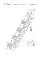
- a suitable antenna systemthat may be used in both transmitter 10 and receiver 12 comprises three half-wave dipoles formed on a sheet of printed circuit board using a conventional etching process.
- the first dipoleincludes elements 152 and 154 .
- the second dipoleincludes elements 156 and 158 .
- the third dipoleincludes elements 160 and 162 .
- Elements 152 - 162are defined by the areas of copper remaining on the board substrate 164 following the etching process.
- the center conductor 166 of a first length of coaxial cable 168is fed through a hole in the printed circuit board and soldered to one element of one of the dipoles.
- the center conductor 170 of a second length of coaxial cable 172is fed through a hole in the printed circuit board and soldered to the other element of that dipole.
- a balanced-to-unbalanced transformer or balun 174is used to match the dipole to the feed 176 , which can be a length of coaxial cable having a grounded shield.
- the shields of both lengths of coaxial cable 168 and 172are coupled to the center tap of balun 174 .
- each dipoleWhen used as the antenna system for transmitter 10 , each dipole corresponds to one of antenna elements 14 , 16 and 18 , and feed 176 receives the corresponding one of signals 42 , 44 and 46 .
- each dipoleWhen used as the antenna system for receiver 12 , each dipole corresponds to one of antenna elements 110 , 112 and 114 , and feed 176 receives the corresponding one of signals 128 , 130 and 132 .
- the communications system of the present inventioncan be characterized as receiver 12 synchronously following the rotating E-field vector of the signal emitted by transmitter 10 .
- the inventionis not limited to that transmission medium.
- the inventionmay communicate signals through waveguide or optical fiber.
- the illustrated embodimentsinclude a transmitter antenna system for radiating or launching radio frequency electromagnetic waves through free space, other embodiments that communicate electromagnetic waves through other media may include radiators suited for launching electromagnetic waves through those media, such as optical radiators for launching light waves through fiber media.
- the illustrated embodimentsinclude a receiver antenna system for receiving the radio frequency electromagnetic waves through free space, other embodiments that communicate electromagnetic waves through other media may include receptors suited for receiving electromagnetic waves through those media, such as optical receptors for fiber media.
- FIG. 13illustrates an optical communications system using a single carrier signal according to another embodiment of the present invention.
- laser 300In transmitter 299 , laser 300 generates a wave having a carrier frequency that passes through beam splitter 302 to generate two waves 304 and 306 having the carrier frequency. Waves 304 and 306 can be linear polarized waves as are commonly generated by conventional lasers. Two information modulators 308 and 310 modulate waves 304 and 306 based on information signal 312 to produce information-modulated waves 314 and 316 , respectively.
- Rotation frequency source 318provides rotation signals 320 and 322 , both having a rotation frequency between the carrier frequency and zero, to optical rotation modulators 324 and 326 ; rotation signals 320 and 322 can be amplitude modulated and phase delayed with respect to one another by optical rotation modulators 324 and 326 in a manner similar to that of the rotation signals described above with respect to FIG. 1 .
- Optical rotation modulators 324 and 326modulate the information-modulated optical waves 314 and 316 , respectively, at the angular or rotation frequency based on rotation signals 320 and 322 , respectively, to produce optical waves 328 and 330 .
- Coupler 332combines and transmits the optical waves 328 and 330 through optical fiber 334 .
- the combination of optical waves 328 and 330has a resultant E-field vector rotating at an angular velocity corresponding to the rotation frequency which is between the carrier frequency and zero.
- beam splitter 336divides the received wave into optical waves 338 and 340 .
- Rotation demodulators 342 and 344receive optical waves 338 and 340 , respectively.
- Rotation frequency source 346similar to rotation frequency source 318 provides the rotation signals 348 and 350 to demodulators 342 and 344 , respectively.
- Rotation demodulators 342 and 344produce demodulated optical waves 352 and 354 based on rotation signals 348 and 350 .
- Optical detectors 356 and 358convert demodulated optical waves 352 and 354 to electronic signals 360 and 362 , respectively.
- Summer 364combines electronic signals 360 and 362 to produce electronic signal 366 .
- Information demodulator 368receives electronic signal 366 to produce information signal 370 which is a reproduction of information signal 312 .
- Laser 300can be selected to be optimized for propagation in optical fiber 334 .
- laser 300can be an aluminum gallium arsenide (AlGaAs) or an indium gallium arsenide (InGaAs) multi-layered, distributed feedback (DFB) laser emitting in the wavelength range 1.3 to 1.55 ⁇ m.
- Optical detectors 356 and 362can be selected to be spectrally responsive to laser 300 .
- optical detectors 356 and 362can be back-biased gallium arsenide (GaAs) diode detectors.
- Information modulators 308 and 310 , rotation modulators 324 and 325 , and rotation demodulators 342 and 344can be variously configured to modulate the phase and/or amplitude of the optical wave as is appropriate.
- the modulators and demodulatorscan be a lithium niobate (LiNbO 3 ) electro-optic modulators, such as Pockel cells.
- multiple transmitter-receiver systemscan communicate over selected information channels, each channel being defined by a selected constant E-field angular velocity different from that of all other such channels.
- FIG. 11illustrates a communications system having multiple transmitter-receiver systems that can communicate over selected information channels.
- Transmitters 178 , 180 , 182 and 184communicate simultaneously with receivers 186 , 188 , 190 and 192 .
- the ellipses (“ . . . ”) between transmitters 182 and 184 and between receivers 190 and 192represent other transmitters and receivers, respectively, because any suitable number of transmitters and receivers may communicate simultaneously; the total number of transmitters or receivers would be N.
- Each of transmitters 178 , 180 , 182 and 184consists of the electronics of transmitter 10 described above with respect to FIG. 1 or the electro-optical components of transmitter 299 described above with respect to FIG. 13 .
- Transmitters 178 , 180 , 182 and 184can share a common antenna system.
- the antenna systemcan be a three-element antenna comprising elements 194 , 196 and 198 .
- Each of transmitters 178 , 180 , 182 and 184receives an information signal 200 , 202 , 204 and 206 , respectively.
- Information signals 200 , 202 , 204 and 206are modulated with the carrier signal by having a modulator (not shown) within each transmitter 178 , 180 , 192 and 184 where the carrier signals are phase locked by a phase-lock circuit (not shown).
- each of transmitters 178 , 180 , 182 and 184produces three amplitude-modulated carrier signals (for the embodiments having a three-element antenna system), such as for example, signals 42 , 44 and 46 described above with respect to FIG. 1 .
- the amplitude-modulated carrier signalscarry amplitude-modulation at a rotation frequency different from that carried by the amplitude-modulated carrier signals produced by all of the others of transmitters 178 , 180 , 182 and 184 .
- each of transmitters 178 , 180 , 182 and 184operates at a different selected rotation frequency that uniquely defines a communication channel.
- each amplitude-modulated signal produced by a transmitteris associated with one of three time-delays.
- a first combiner 208combines the amplitude-modulated signal produced by each of transmitters 178 , 180 , 182 and 184 that is associated with the first time-delay.
- a second combiner 210combines the amplitude-modulate signal produced by each of transmitters 178 , 180 , 182 and 184 that is associated with the second time-delay.
- a third combiner 212combines the amplitude-modulate signal produced by each of transmitters 178 , 180 , 182 and 184 that is associated with the third time-delay.
- Antenna element 194receives the output of first combiner 208 .
- Antenna element 196receives the output of second combiner 210 .
- Antenna element 198receives the output of third combiner 212 .
- the transmitter antenna systemtransmits a signal 213 representing multiple combined communication channels in the same manner as described above with respect to the single-channel system illustrated in FIG. 1 .
- Each of receivers 186 , 188 , 190 and 192consists of the electronics of receiver 12 described above with respect to FIG. 1 or the electro-optical components of receiver 335 described above with respect to FIG. 13 .
- Receivers 186 , 188 , 190 and 192can share a common antenna system that comprises elements 214 , 216 and 218 for the example of a three-element antenna at the receivers.
- the receiver antenna systemreceives multiple communication channels.
- a first splitter 220splits the amplitude-modulated signal received by antenna element 214 into multiple amplitude-modulated signals associated with the first time-delay.
- a second splitter 222splits the amplitude-modulated signal received by antenna element 216 into multiple amplitude-modulated signals associated with the second time-delay.
- a third splitter 224splits the amplitude-modulated signal received by antenna element 218 into multiple amplitude-modulated signals associated with the third time-delay.
- a phase-lock loop (PLL) circuit(not shown) locks the phase of the signals used to demodulate the amplitude-modulated signals received by antenna elements 214 , 216 and 218 .
- PLLphase-lock loop
- Each of receivers 186 , 188 , 190 and 192operates at a different selected rotation frequency that uniquely defines one of the communication channels.
- Receivers 186 , 188 , 190 and 192generate the reproduced information signals 226 , 228 , 230 and 232 in response to the amplitude-modulated signals provided by each of splitters 220 , 222 and 224 in the same manner described above with respect to FIG. 1 in which receiver 12 generates reproduced information signal 138 .
- the rotation frequencyprovides channel selectivity that is additional to that provided by the frequency of the carrier signal.
- one of receivers 186 , 188 , 190 and 192tuned to a selected channel, i.e., operating at a certain rotation frequency, does not sense interference from the communication signals produced by transmitters 178 , 180 , 182 and 184 operating on other channels, i.e., at other rotation frequencies.
- Transmitters 178 , 180 , 182 and 184 and receivers 186 , 188 , 190 and 192may all operate simultaneously at the same carrier signal frequency, yet only one of receivers 186 , 188 , 190 and 192 communicates with each of transmitters 178 , 180 , 182 and 184 , respectively, because the rotation frequency rather than the carrier frequency provides the channel selectivity.
- a communications system having multiple transmitters sharing a common transmitter antenna system and multiple receivers sharing a common receiver antenna system, as illustrated in FIG. 11,is economical because it minimizes the number of antenna elements. Nevertheless, a communications system in which each transmitter includes its own antenna system would operate in an equivalent manner.
- a systemmay include multiple transmitters and receivers such as transmitter 10 and receiver 12 in FIG. 1 and may simultaneously communicate via a corresponding multiplicity of channels.
- Each transmitter 10 operating at a rotation frequency different from that of all other transmitters 10defines a unique communication channel. All of the transmitters 10 and receivers 12 of such a system may operate simultaneously at the same carrier signal frequency, yet only one of the receivers 12 communicates with each of the transmitters 10 .
- channelsshould be allocated an appropriate bandwidth in the domain of the second frequency to transmit the information effectively.
- an information signal having a 6 MHz bandwidthwould be represented by a signal in the second frequency domain having a 6 MHz bandwidth.
- Each periodic path frequency source defining a different channelshould be selected to separate the corresponding signals in the second frequency domain from one another to avoid overlapping.
- the rotation frequencies corresponding to different channelsshould be separated from one another by at least 6 MHz.
- the lowest rotation frequencyshould be at least 3 MHz to provide sufficient room above zero for the channel, and the highest rotation frequency should be at least 3 MHz below the carrier.
- the second frequencyshould be less than the carrier frequency.
- FIG. 16is a block diagram of a communications system using two different carrier signals according to an embodiment of the present invention.
- a transmitter 600includes two differential carrier frequency sources 602 and 604 , two information modulators 606 and 608 , and two transmission medium couplers 610 and 612 .
- Transmitter 600sends EM wave 614 through a transmission medium (not shown) to receiver 616 .
- Receiver 616includes two transmission medium decouplers 618 and 620 , two filters 622 and 624 , summer 626 and information demodulator 628 .
- Information modulator 606receives information signal 630 and upper differential carrier frequency signal 632 from differential carrier frequency source 602 to produce signal 636 .
- information modulator 608receives information signal 630 and lower differential carrier frequency signal 634 from differential carrier frequency source 604 to produce signal 638 .
- Information signal 630can be any suitable analog signal produced by any suitable source, such as a video signal or an audio signal, that is to be communicated to receiver 616 (or other suitable receiver).
- information signal 630can be in digital format.
- Differential carrier frequency sources 602 and 604can include any suitable circuits or systems, such as a conventional sine-wave generator or oscillator, for providing carrier signals 632 and 634 , respectively.
- Carrier signals 632 and 634should have a frequency that facilitates their modulation with information signal 630 for the given transmission medium.
- Transmission medium coupler 610 and 612receives signals 636 and 638 , respectively, to produce two EM waves the superposition of which is EM wave 614 .
- the EM wave sent by transmission medium coupler 610has an E field vector terminus that traces a nonlinear periodic path.
- the EM wave sent by transmission medium coupler 612has an E field vector terminus that traces the same nonlinear periodic path but in the opposite direction.
- coupler 610can send an EM wave that is left-hand circularly polarized at one carrier frequency; coupler 612 can send an EM wave that is right-hand circularly polarized at another carrier frequency.
- Receiver 616receives EM wave 614 at transmission medium decouplers 618 and 620 .
- Transmission medium decoupler 618receives the EM wave sent by transmission medium coupler 610 and produces signal 640 ;
- transmission medium decoupler 620receives the EM wave sent by transmission medium coupler 612 and produces signal 642 .
- Filters 622 and 624receive signals 640 and 642 , respectively, and produce signals 644 and 646 , respectively.
- Filters 622 and 624can be notch filters and impedance matching circuits that prevent cross-coupling of the signals. Filters 622 and 624 can have a spectral bandwidth appropriate for signals 640 and 642 , respectively, centered about the carrier frequencies of differential carrier frequency sources 602 and 604 , respectively.
- Summer 626sums signals 644 and 646 to produce signal 648 .
- Signal 648contains information at a new carrier frequency being the average of the upper differential carrier frequency and the lower differential carrier frequency; information is no longer present at the upper and lower differential carrier frequencies.
- an information channelexists in a manner analogous to the communications systems based on a single carrier signal discussed above, where the information is carried at a new carrier frequency that is the average of the upper and lower differential carrier frequencies, and the E-field vector traces a nonlinear periodic path at a frequency equal to one-half of the difference of the upper and lower differential carrier frequencies.
- the E-field vectorcan trace a nonlinear periodic path at any suitable frequency between the new carrier frequency and zero, but the frequency of the path traversed should be greater than the highest frequency of the information signal.
- the transmission medium coupler driven by the sideband signal having the higher of the two differential carrier frequenciesdictates the direction in which the E-field vector traces the nonlinear periodic path.
- transmission medium coupler 610induces clockwise rotation of the E-field vector of the EM wave it sends
- transmission medium coupler 612induces counterclockwise rotation of the E-field vector of the EM wave it sends
- the E-field vector of resulting EM wave 614rotates in a clockwise direction if differential carrier frequency source 602 produces a higher frequency than differential carrier frequency source 604
- rotates in a counterclockwise direction if differential carrier frequency source 604 produces a higher frequency than differential carrier frequency source 602rotates in a counterclockwise direction if differential carrier frequency source 604 produces a higher frequency than differential carrier frequency source 602 .
- Information demodulator 628receives signal 648 and produces signal 650 which is a reproduction of information signal 630 .
- Information demodulator 628demodulates signal 648 based on the new carrier frequency being the average of the upper and lower differential carrier frequencies.
- Information demodulator 628can be, for example, a conventional AM receiver.
- transmission mediumcan be free space, a waveguide or a optical fiber.
- transmission medium couplers 610 and 612can be antennas optimized for those carrier frequencies.
- transmission medium decouplers 618 and 620can be antennas optimized for those carrier frequencies.
- an appropriate antennacan comprise dipole antennas, helical antennas, and/or phased-array antenna, etc.
- transmission medium couplers 610 and 612can be fiber optic couplers; transmission medium coupler 618 and 620 and summer 626 can be an optical detector; and differential carrier frequency sources 602 and 604 can be lasers each producing a wave having an E-field vector rotating in opposite directions.
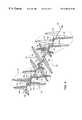
- FIG. 12shows a communications system based on two different carrier signals according to another embodiment of the present invention.
- the communications systemincludes a transmitter 234 and a receiver 236 .
- Transmitter 234includes a dual helical antenna system comprising two helical antenna elements 238 and 240 .
- Transmitter 234further includes transmitter electronics comprising a lower differential carrier frequency source 242 , an upper differential carrier frequency source 244 , two amplitude modulators 246 and 248 , two amplifiers 250 and 252 , and two notch filter and impedance matching circuits 254 and 256 .
- Modulators 246 and 248each receive an information signal 258 , which may be any suitable analog signal produced by any suitable source, such as a video signal or an audio signal, that it is desired to communicate to receiver 236 (or other suitable receiver).
- the sourcemay be, for example, that of a conventional NTSC television channel having a 6 MHz bandwidth.
- Upper differential carrier frequency source 244produces an upper sideband signal 260 having an upper differential carrier frequency that is equal to the predetermined carrier frequency plus the predetermined rotation frequency.
- Lower differential carrier frequency source 242produces a lower sideband signal 262 having a lower differential carrier frequency that is equal to a predetermined carrier frequency minus a predetermined rotation frequency.
- Frequency sources 242 and 244may include any suitable circuits or systems, such as a conventional sine-wave generator or oscillator.
- the modulated lower sideband signal 264is coupled to antenna element 238 via amplifier 250 .
- the modulated upper sideband signal 266is coupled to antenna element 240 via amplifier 252 .
- Amplifiers 250 and 252should have a bandwidth of at least 6 MHz if information signal 34 is a conventional NTSC television signal.
- Helical antenna elements 238 and 240can have opposite twists and can be disposed generally coaxially along a central supporting structure 268 .
- antenna element 238may have a right-hand twist
- antenna element 240may have a left-hand twist.
- antenna element 238radiates a right-hand circularly polarized wave
- antenna element 240radiates a left-hand circularly polarized wave.
- a reflector 270(shown in cross-section in FIG. 12 for clarity) is disposed at the proximal end of the antenna system.
- resultant transmitted electromagnetic wave 272 radiated by the antenna systemhas similar characteristics as transmitted signal 78 described above with respect to the embodiment illustrated in FIG. 1 .
- resultant transmitted wave 272has an E-field vector rotating at an angular velocity different from the upper differential carrier frequency and different from the lower differential carrier frequency.
- helical antenna element 240induces clockwise rotation of the E-field vector of the EM wave it sends
- helical antenna element 238induces counterclockwise rotation of the E-field vector of the EM wave it sends
- the E-field vector of wave 272rotates in a clockwise direction because upper differential carrier frequency source 244 produces a higher frequency than lower differential carrier frequency source 242 .
- helical antenna element 240induces counterclockwise rotation of the E-field vector of the EM wave it sends
- helical antenna element 238induces clockwise rotation of the E-field vector of the EM wave it sends
- the E-field vector of wave 272rotates in a counterclockwise direction because upper differential carrier frequency source 244 produces a higher frequency than lower differential carrier frequency source 242 .
- Notch filter and impedance matching circuits 254 and 256prevent cross-coupling of the signals.
- Circuit 254has a 6 MHz notch centered at the frequency of the upper sideband and thus passes only the lower sideband signal.
- circuit 256has a 6 MHz notch centered at the frequency of the lower sideband and thus passes only the upper sideband signal.
- Circuits 254 and 256can also include suitable impedance-matching circuits, such as baluns.
- transmitter 234may be understood by comparing the communications system based on two different carrier signals with the communications system based on a single carrier signal.
- the E-field vector of the propagating waveis rotating; the wave produces no sidebands although sidebands would be present if only one component of the wave produced a given antenna element were considered. Sidebands are eliminated due to the summation of the radiated wave components from the other antenna elements of the antenna system.
- the sidebandscancel each other and no sidebands exist in the received resultant wave.
- These putative sideband wavesin effect cancel each other because, although they cross or rotate aligned each other, they do so at the rate of the predetermined carrier frequency and thus cannot be distinguished from the predetermined carrier signal being the difference between the upper differential carrier signal and the lower differential carrier signal.
- the antenna systemis of the coaxial helical type.
- the coaxial helical antenna elements of the alternative embodiment illustrated in FIG. 12cause the putative sidebands to cancel each other. Nevertheless, rather than inducing sideband frequencies by driving an antenna element with a carrier wave amplitude-modulated with a rotation frequency, as in the embodiment described above, in this alternative embodiment the sideband frequencies are generated directly by driving one helical antenna element with a signal at the frequency of the upper sideband and the other helical antenna element with a signal at the frequency of the lower sideband.
- Helical antenna element 240radiates a wave with a rotating E-field vector having an angular velocity equal to the lower differential carrier frequency.
- Helical antenna element 238radiates a wave with a rotating E-field vector having an angular velocity in the opposite direction equal to the upper differential carrier frequency.
- Antenna elements 238 and 240need not be exactly coaxial so long as the receiving antenna system is disposed in the far-field of antenna elements 238 and 240 . Thus, they could be placed side-by-side in many communications systems. If the separation between transmitter and receiver is great, such as the distance between a satellite and ground station, antenna elements 238 and 240 could likely be separated by several meters without significantly degrading system performance. The optimal physical construction of the dual helical antenna system thus depends upon various antenna design factors in view of the intended use of the communications system.
- Receiver 236is structurally similar to transmitter 234 .
- Receiver 236includes a dual helical antenna system comprising two helical antenna elements 274 and 276 having opposite twists coaxially mounted on a supporting structure 277 .
- a reflector 278(shown in cross-section in FIG. 12 for clarity) is mounted at the proximal end of the antenna system.
- Receiver 236further includes receiver electronics comprising a lower differential carrier frequency filter 280 , an upper differential carrier frequency filter 282 , a summing circuit 284 , an amplitude modulation detector circuit 286 , and two notch filter and impedance matching circuits 288 and 290 .
- Lower differential carrier frequency filter 280has a bandpass centered at the frequency of the lower sideband
- upper differential carrier frequency filter 282has a bandpass centered at the frequency of the upper sideband.
- Notch filter and impedance matching circuits 288 and 290can be identical to circuits 254 and 256 .
- Circuit 288has a 6 MHz notch centered at the frequency of the lower sideband and thus passes only the upper sideband signal.
- circuit 290has a 6 MHz notch centered at the frequency of the upper sideband and thus passes only the lower sideband signal.
- Amplitude modulation detector circuit 286may be of conventional construction, and thus may include amplifiers, detectors, a local oscillator, automatic gain control and any other circuitry known in the art that is commonly included in amplitude modulation radio receivers. Amplitude modulation detector circuit 286 should be tuned to receive a signal at the new carrier frequency, i.e., the average of the upper and lower differential carrier or sideband frequencies.
- Lower differential carrier frequency filter 280is coupled to antenna element 274
- upper differential carrier frequency filter 282is coupled to antenna element 276 .
- the inputs of summing circuit 284are coupled to the outputs of filters 280 and 282 .
- Summing circuit 284receives a lower sideband signal 292 produced by filter 280 and an upper sideband signal 294 produced by filter 282 .
- the receiver electronicsfunction in a manner that is essentially the inverse of the transmitter electronics. As described above with respect to transmitter 234 , the sum of the sidebands is the carrier; the sideband frequencies cancel each other.
- Amplitude modulation detector circuit 286recovers a reproduced information signal 298 that corresponds to information signal 258 .
- FIG. 14illustrates an optical communications system using two different carrier frequencies according to another embodiment of the present invention.
- lasers 702 and 704produce optical waves 706 and 708 , respectively, at two different carrier frequencies carrier, f 1 , and f 2 , respectively (or wavelengths ⁇ 1 and ⁇ 2 ).
- Modulators 710 and 712modulate waves 706 and 708 , respectively, with information signal 701 to produce waves 714 and 716 , respectively.
- Modulator 710 and/or 712can modify the phase and amplitude of waves 706 and/or 708 , respectively, so that the E-field vector for the waves rotate in opposite directions.
- lasers 702 and 704can be configured to produce waves 706 and 708 , respectively, with an E-field vector rotating in opposite directions.
- wave 706is circularly polarized in one direction and wave 708 is circularly polarized in the opposite direction.
- Coupler 718combines waves 714 and 716 to produce a superposed wave which is sent over optical fiber 720 .
- Receiver 722includes optical detector 724 that receives the superposed optical signal from optical fiber 720 , and information demodulator 728 .
- Optical detector 724receives waves 734 and 736 to produce signal 728 .
- Optical detector 724is optimized to receive center wavelengths ⁇ 1 and ⁇ 2 and effectively acts as a spectral filter due to an optical detector's inherent spectral response.
- Information demodulator 728receives signal 728 to produce signal 730 which the reproduction of information signal 701 .
- the carrier wavelength detected by optical detector 724is the average of carrier wavelengths ⁇ 1 and ⁇ 2 .
- the superposed wave detected by optical detector 724has an E-field vector rotating at an angular velocity equal to one-half of the difference of carrier wavelengths ⁇ 1 and ⁇ 2 . For the case where wave 706 rotates clockwise and wave 708 rotates counterclockwise, if ⁇ 1 is shorter than 2 ⁇ , the E-field vector of the superposed wave is clockwise; if ⁇ 1 is longer than ⁇ 2 , the E-field vector of the superposed wave is counterclockwise.
- Lasers 702 and 704can be selected to be optimized for propagation in optical fiber 334 .
- lasers 702 and 704can be an aluminum gallium arsenide (AlGaSa) or an indium gallium arsenide (InGaAs) multi-layered, distributed feedback (DFB) lasers emitting in the wavelength range 1.3 to 1.55 ⁇ m.
- Optical detector 724can be selected to be spectrally responsive to lasers 702 and 704 .
- optical detectors 738 and 740can be back-biased gallium arsenide (GaAs) diode detectors.
- Modulators 710 and 712can be variously configured to modulate the phase and/or amplitude of the optical wave as is appropriate.
- modulators 710 and 712can be a lithium niobate (LiNbO 3 ) electro-optic modulators, such as Pockel cells.
- the communications systemmay include multiple transmitters 234 and receivers 236 that communicate simultaneously via a corresponding multiplicity of channels. All of transmitters 234 and receivers 236 of such a system may operate simultaneously, yet only one of receivers 236 communicates with each of transmitters 234 .
- the rotation frequencyprovides the channel selectivity.
- Each transmitter 234 and receiver 236operates at a selected rotation frequency.
- lower differential carrier frequency source 242is set to a frequency of the carrier frequency minus the selected rotation frequency
- upper differential carrier frequency source 244is set to a frequency of the carrier frequency plus the selected rotation frequency.
- lower differential carrier frequency filter 280is set to a frequency of the carrier frequency minus the selected rotation frequency
- upper differential carrier frequency filter 282is set to a frequency of the carrier frequency plus the selected rotation frequency.
- the new carrier frequency of resultant transmitted wave 272has a frequency that is the average of the upper and lower differential carrier frequencies.
- helical antenna element 240induces clockwise rotation of the E-field vector of the EM wave it sends
- helical antenna element 238induces counterclockwise rotation of the E-field vector of the EM wave it sends
- the E-field vector of wave 272rotates in a clockwise direction because upper differential carrier frequency source 244 produces a higher frequency than lower differential carrier frequency source 242 .
- helical antenna element 240induces counterclockwise rotation of the E-field vector of the EM wave it sends
- helical antenna element 238induces clockwise rotation of the E-field vector of the EM wave it sends
- the E-field vector of wave 272rotates in a counterclockwise direction because upper differential carrier frequency source 244 produces a higher frequency than lower differential carrier frequency source 242 .
- Filters 280 and 282may include varactors or other tunable circuitry to facilitate tuning receiver 236 to a selected channel.
- receiver 236may further include a switch that an operator may use to swap the two signals coupled to antenna elements 276 and 274 with one another to facilitate reception of the transmitted signal regardless of whether its polarization is right-hand or left-hand.
- channelsshould be allocated an appropriate bandwidth in the domain of the second frequency to transmit the information effectively.
- an information signal having a 6 MHz bandwidthwould be represented by a lower putative sideband having a 6 MHz bandwidth and an upper putative sideband having a 6 MHz bandwidth.
- the lower and upper differential carrier frequencies corresponding to these putative sidebandsshould be selected to separate the putative sidebands from one another in the second frequency domain to avoid overlapping.
- Transmitter 10is illustrated in FIG. 1 paired with receiver 12 only for illustrative purposes.
- transmitter 234is illustrated in FIG. 12 paired with receiver 236 only for illustrative purposes.
- Transmitter 10 illustrated in FIG. 1may communicate with receiver 236 illustrated in FIG. 12 .
- transmitter 234 illustrated in FIG. 12may communicate with receiver 12 illustrated in FIG. 1 .
- the embodiment illustrated in FIG. 1can use a dipole antenna system
- the embodiment illustrated in FIG. 12can use a coaxial helical antenna system
- an information channelis defined by a wave having an E-field vector rotating at a selected angular velocity.
- a wavecan have an essentially fixed or constant carrier frequency and an E-field vector rotating at an angular velocity modulated in accordance with the information.
- the rotating E-field vectorcan be phase modulated with information or frequency modulated with information.
- the present inventionprovides an additional communication domain that is distinct from frequency and amplitude. It may be used in conjunction with conventional frequency-division channel multiplexing and any other multiplexing systems known in the art to define a greater number of communication channels than in conventional communications systems. Furthermore, because noise is distributed over all channels of the system, much less noise is present in each channel than in conventional systems. The present invention thus facilitates the design of very low power communications systems.
Landscapes
- Engineering & Computer Science (AREA)
- Computer Networks & Wireless Communication (AREA)
- Signal Processing (AREA)
- Physics & Mathematics (AREA)
- Electromagnetism (AREA)
- Near-Field Transmission Systems (AREA)
- Variable-Direction Aerials And Aerial Arrays (AREA)
Abstract
Description
Claims (58)
Priority Applications (21)
| Application Number | Priority Date | Filing Date | Title |
|---|---|---|---|
| US08/853,833US6204810B1 (en) | 1997-05-09 | 1997-05-09 | Communications system |
| MYPI98000121AMY129618A (en) | 1997-05-09 | 1998-01-12 | Communications system |
| ARP980100382AAR011095A1 (en) | 1997-05-09 | 1998-01-28 | A METHOD FOR TRANSMITING INFORMATION USING AN ELECTRO-MAGNETIC WAVE AND AN INFORMATION TRANSMITTING DEVICE TO TAKE SUCH A METHOD INTO PRACTICE |
| US09/064,525US6271790B2 (en) | 1997-05-09 | 1998-04-23 | Communication system |
| TW087107061ATW406488B (en) | 1997-05-09 | 1998-05-07 | Communications system |
| ZA9803864AZA983864B (en) | 1997-05-09 | 1998-05-07 | Communications system. |
| CA002290613ACA2290613C (en) | 1997-05-09 | 1998-05-08 | Communications system |
| AU74748/98AAU7474898A (en) | 1997-05-09 | 1998-05-08 | Communications system |
| AT98922139TATE372613T1 (en) | 1997-05-09 | 1998-05-08 | METHOD FOR SENDING AND RECEIVING INFORMATION WITH A ROTATION FREQUENCY FOR EACH CHANNEL GREATER THAN ZERO AND LESS THAN THE CORRESPONDING CARRIER FREQUENCY |
| NZ500827ANZ500827A (en) | 1997-05-09 | 1998-05-08 | Multi-channel RF communication using polarised waves with E vector rotation frequency different from carrier frequency |
| CNB988069911ACN1322631C (en) | 1997-05-09 | 1998-05-08 | Communications system |
| HK01100729.7AHK1030104B (en) | 1997-05-09 | 1998-05-08 | Communications system |
| JP54851398AJP4138894B2 (en) | 1997-05-09 | 1998-05-08 | Communication system |
| HK00105174.7AHK1026778B (en) | 1997-05-09 | 1998-05-08 | Method for transmitting and receiving information using a rotation frequency for each channel greater than zero and less than the associated carrier frequency |
| PCT/US1998/009387WO1998050983A1 (en) | 1997-05-09 | 1998-05-08 | Communications system |
| EP98922139AEP0988663B1 (en) | 1997-05-09 | 1998-05-08 | Method for transmitting and receiving information using a rotation frequency for each channel greater than zero and less than the associated carrier frequency |
| DE69838384TDE69838384T2 (en) | 1997-05-09 | 1998-05-08 | A method of transmitting and receiving information at a rotational frequency for each channel greater than zero and less than the corresponding carrier frequency |
| ARP980102179AAR015809A1 (en) | 1997-05-09 | 1998-05-11 | METHOD AND APPLIANCE TO TRANSMIT INFORMATION AND METHOD AND APPARATUS TO RECEIVE INFORMATION USING AN ELECTROMAGNETIC WAVE |
| IDW991547AID28950A (en) | 1997-05-09 | 1998-08-05 | COMMUNICATION SYSTEM |
| US09/899,821US6570536B2 (en) | 1997-05-09 | 2001-07-09 | Communications system |
| CY20071101536TCY1107046T1 (en) | 1997-05-09 | 2007-12-03 | METHOD FOR TRANSFERING AND RECEIVING INFORMATION USING A ROTATION FREQUENCY FOR EVERY CHANNEL BETTER FROM ZERO AND SMALLER |
Applications Claiming Priority (1)
| Application Number | Priority Date | Filing Date | Title |
|---|---|---|---|
| US08/853,833US6204810B1 (en) | 1997-05-09 | 1997-05-09 | Communications system |
Related Child Applications (1)
| Application Number | Title | Priority Date | Filing Date |
|---|---|---|---|
| US09/064,525Continuation-In-PartUS6271790B2 (en) | 1997-05-09 | 1998-04-23 | Communication system |
Publications (1)
| Publication Number | Publication Date |
|---|---|
| US6204810B1true US6204810B1 (en) | 2001-03-20 |
Family
ID=25317026
Family Applications (2)
| Application Number | Title | Priority Date | Filing Date |
|---|---|---|---|
| US08/853,833Expired - Fee RelatedUS6204810B1 (en) | 1997-05-09 | 1997-05-09 | Communications system |
| US09/064,525Expired - LifetimeUS6271790B2 (en) | 1997-05-09 | 1998-04-23 | Communication system |
Family Applications After (1)
| Application Number | Title | Priority Date | Filing Date |
|---|---|---|---|
| US09/064,525Expired - LifetimeUS6271790B2 (en) | 1997-05-09 | 1998-04-23 | Communication system |
Country Status (5)
| Country | Link |
|---|---|
| US (2) | US6204810B1 (en) |
| AR (2) | AR011095A1 (en) |
| CY (1) | CY1107046T1 (en) |
| MY (1) | MY129618A (en) |
| ZA (1) | ZA983864B (en) |
Cited By (12)
| Publication number | Priority date | Publication date | Assignee | Title |
|---|---|---|---|---|
| US6407677B1 (en)* | 1998-12-21 | 2002-06-18 | Valeo Securite Habitacle | Device for low-frequency communication by magnetic coupling |
| US20020089726A1 (en)* | 2000-07-18 | 2002-07-11 | Zhan He | System and method for wavelength modulated free space optical communication |
| US20040185843A1 (en)* | 2003-03-18 | 2004-09-23 | Wolfgang Bredow | Remote controlled industrial equipment |
| US20040185781A1 (en)* | 1999-10-21 | 2004-09-23 | Shervin Moloudi | System and method for reducing phase noise |
| US7053813B1 (en)* | 2004-04-22 | 2006-05-30 | University Corporation For Atmospheric Research | Radar system |
| US7145954B1 (en)* | 2000-06-12 | 2006-12-05 | Time Domain Corporation | Method and apparatus for mapping pulses to a non-fixed layout |
| US8718563B2 (en) | 1999-10-21 | 2014-05-06 | Broadcom Corporation | System and method for signal limiting |
| RU2571409C2 (en)* | 2013-12-04 | 2015-12-20 | Федеральное государственное бюджетное образовательное учреждение высшего профессионального образования "Ярославский государственный университет им. П.Г. Демидова" | Method of increasing amount of frequency resource |
| US20170363730A1 (en)* | 2014-12-23 | 2017-12-21 | Balluff Gmbh | Proximity sensor and method for measuring the distance from a target |
| US20180343049A1 (en)* | 2017-05-26 | 2018-11-29 | Starry, Inc. | N-way polarization diversity for wireless access networks |
| US10153824B2 (en)* | 2014-11-13 | 2018-12-11 | Hitachi, Ltd. | Wireless communication system and system using same |
| US10804997B2 (en) | 2017-02-10 | 2020-10-13 | CTwists, LLC | Apparatus and method for generating and capturing a transmission wave and apparatus and method for transmitting and receiving digital information |
Families Citing this family (180)
| Publication number | Priority date | Publication date | Assignee | Title |
|---|---|---|---|---|
| KR20010079835A (en)* | 1998-09-16 | 2001-08-22 | 추후 | Wireless optical communications without electronics |
| US20030119473A1 (en)* | 1998-11-09 | 2003-06-26 | Smith Stephen H. | Adjustable balanced modulator |
| KR100831177B1 (en)* | 2005-10-08 | 2008-05-21 | 삼성전자주식회사 | Transmitter and transmission method of smart antenna communication system |
| US7792548B2 (en)* | 2006-09-28 | 2010-09-07 | Broadcom Corporation | Multiple frequency antenna array for use with an RF transmitter or transceiver |
| US8077103B1 (en) | 2007-07-07 | 2011-12-13 | The United States Of America As Represented By The Administrator Of The National Aeronautics And Space Administration | Cup waveguide antenna with integrated polarizer and OMT |
| US8830903B2 (en)* | 2010-05-28 | 2014-09-09 | Comtech Ef Data Corp. | Identification, alignment and cross polarization optimization for orthogonal polarized transmission and relay systems |
| WO2012120657A1 (en)* | 2011-03-09 | 2012-09-13 | 株式会社日立製作所 | Polarization-angle-division diversity wireless transmitter, wireless receiver, and wireless communication system |
| US9225069B2 (en) | 2011-10-18 | 2015-12-29 | California Institute Of Technology | Efficient active multi-drive radiator |
| WO2013123090A1 (en) | 2012-02-13 | 2013-08-22 | California Institute Of Technology | Sensing radiation metrics through mode-pickup sensors |
| US9686070B2 (en) | 2012-02-17 | 2017-06-20 | California Institute Of Technology | Dynamic polarization modulation and control |
| WO2014018927A1 (en) | 2012-07-26 | 2014-01-30 | California Institute Of Technology | Optically driven active radiator |
| US10009065B2 (en) | 2012-12-05 | 2018-06-26 | At&T Intellectual Property I, L.P. | Backhaul link for distributed antenna system |
| US9113347B2 (en) | 2012-12-05 | 2015-08-18 | At&T Intellectual Property I, Lp | Backhaul link for distributed antenna system |
| US9525524B2 (en) | 2013-05-31 | 2016-12-20 | At&T Intellectual Property I, L.P. | Remote distributed antenna system |
| US9999038B2 (en) | 2013-05-31 | 2018-06-12 | At&T Intellectual Property I, L.P. | Remote distributed antenna system |
| US8897697B1 (en) | 2013-11-06 | 2014-11-25 | At&T Intellectual Property I, Lp | Millimeter-wave surface-wave communications |
| US9209902B2 (en) | 2013-12-10 | 2015-12-08 | At&T Intellectual Property I, L.P. | Quasi-optical coupler |
| US9490862B2 (en)* | 2014-02-18 | 2016-11-08 | Raytheon Company | Reflective-type antenna band and polarization selectable transceiver using a rotatable quarter-wave plate |
| US9692101B2 (en) | 2014-08-26 | 2017-06-27 | At&T Intellectual Property I, L.P. | Guided wave couplers for coupling electromagnetic waves between a waveguide surface and a surface of a wire |
| US9768833B2 (en) | 2014-09-15 | 2017-09-19 | At&T Intellectual Property I, L.P. | Method and apparatus for sensing a condition in a transmission medium of electromagnetic waves |
| US10063280B2 (en) | 2014-09-17 | 2018-08-28 | At&T Intellectual Property I, L.P. | Monitoring and mitigating conditions in a communication network |
| US9628854B2 (en) | 2014-09-29 | 2017-04-18 | At&T Intellectual Property I, L.P. | Method and apparatus for distributing content in a communication network |
| US9615269B2 (en) | 2014-10-02 | 2017-04-04 | At&T Intellectual Property I, L.P. | Method and apparatus that provides fault tolerance in a communication network |
| US9685992B2 (en) | 2014-10-03 | 2017-06-20 | At&T Intellectual Property I, L.P. | Circuit panel network and methods thereof |
| US9503189B2 (en) | 2014-10-10 | 2016-11-22 | At&T Intellectual Property I, L.P. | Method and apparatus for arranging communication sessions in a communication system |
| US9973299B2 (en) | 2014-10-14 | 2018-05-15 | At&T Intellectual Property I, L.P. | Method and apparatus for adjusting a mode of communication in a communication network |
| US9762289B2 (en) | 2014-10-14 | 2017-09-12 | At&T Intellectual Property I, L.P. | Method and apparatus for transmitting or receiving signals in a transportation system |
| US9769020B2 (en) | 2014-10-21 | 2017-09-19 | At&T Intellectual Property I, L.P. | Method and apparatus for responding to events affecting communications in a communication network |
| US9312919B1 (en) | 2014-10-21 | 2016-04-12 | At&T Intellectual Property I, Lp | Transmission device with impairment compensation and methods for use therewith |
| US9577306B2 (en) | 2014-10-21 | 2017-02-21 | At&T Intellectual Property I, L.P. | Guided-wave transmission device and methods for use therewith |
| US9520945B2 (en) | 2014-10-21 | 2016-12-13 | At&T Intellectual Property I, L.P. | Apparatus for providing communication services and methods thereof |
| US9564947B2 (en) | 2014-10-21 | 2017-02-07 | At&T Intellectual Property I, L.P. | Guided-wave transmission device with diversity and methods for use therewith |
| US9780834B2 (en) | 2014-10-21 | 2017-10-03 | At&T Intellectual Property I, L.P. | Method and apparatus for transmitting electromagnetic waves |
| US9627768B2 (en) | 2014-10-21 | 2017-04-18 | At&T Intellectual Property I, L.P. | Guided-wave transmission device with non-fundamental mode propagation and methods for use therewith |
| US9653770B2 (en) | 2014-10-21 | 2017-05-16 | At&T Intellectual Property I, L.P. | Guided wave coupler, coupling module and methods for use therewith |
| US9544006B2 (en) | 2014-11-20 | 2017-01-10 | At&T Intellectual Property I, L.P. | Transmission device with mode division multiplexing and methods for use therewith |
| US9800327B2 (en) | 2014-11-20 | 2017-10-24 | At&T Intellectual Property I, L.P. | Apparatus for controlling operations of a communication device and methods thereof |
| US10009067B2 (en) | 2014-12-04 | 2018-06-26 | At&T Intellectual Property I, L.P. | Method and apparatus for configuring a communication interface |
| US10243784B2 (en) | 2014-11-20 | 2019-03-26 | At&T Intellectual Property I, L.P. | System for generating topology information and methods thereof |
| US10340573B2 (en) | 2016-10-26 | 2019-07-02 | At&T Intellectual Property I, L.P. | Launcher with cylindrical coupling device and methods for use therewith |
| US9954287B2 (en) | 2014-11-20 | 2018-04-24 | At&T Intellectual Property I, L.P. | Apparatus for converting wireless signals and electromagnetic waves and methods thereof |
| US9997819B2 (en) | 2015-06-09 | 2018-06-12 | At&T Intellectual Property I, L.P. | Transmission medium and method for facilitating propagation of electromagnetic waves via a core |
| US9742462B2 (en) | 2014-12-04 | 2017-08-22 | At&T Intellectual Property I, L.P. | Transmission medium and communication interfaces and methods for use therewith |
| US9654173B2 (en) | 2014-11-20 | 2017-05-16 | At&T Intellectual Property I, L.P. | Apparatus for powering a communication device and methods thereof |
| US9680670B2 (en) | 2014-11-20 | 2017-06-13 | At&T Intellectual Property I, L.P. | Transmission device with channel equalization and control and methods for use therewith |
| US9461706B1 (en) | 2015-07-31 | 2016-10-04 | At&T Intellectual Property I, Lp | Method and apparatus for exchanging communication signals |
| JP6228108B2 (en) | 2014-12-18 | 2017-11-08 | 株式会社日立製作所 | Wireless communication system |
| US10144036B2 (en) | 2015-01-30 | 2018-12-04 | At&T Intellectual Property I, L.P. | Method and apparatus for mitigating interference affecting a propagation of electromagnetic waves guided by a transmission medium |
| US9876570B2 (en) | 2015-02-20 | 2018-01-23 | At&T Intellectual Property I, Lp | Guided-wave transmission device with non-fundamental mode propagation and methods for use therewith |
| US9749013B2 (en) | 2015-03-17 | 2017-08-29 | At&T Intellectual Property I, L.P. | Method and apparatus for reducing attenuation of electromagnetic waves guided by a transmission medium |
| US10224981B2 (en) | 2015-04-24 | 2019-03-05 | At&T Intellectual Property I, Lp | Passive electrical coupling device and methods for use therewith |
| US9705561B2 (en) | 2015-04-24 | 2017-07-11 | At&T Intellectual Property I, L.P. | Directional coupling device and methods for use therewith |
| US9948354B2 (en) | 2015-04-28 | 2018-04-17 | At&T Intellectual Property I, L.P. | Magnetic coupling device with reflective plate and methods for use therewith |
| US9793954B2 (en) | 2015-04-28 | 2017-10-17 | At&T Intellectual Property I, L.P. | Magnetic coupling device and methods for use therewith |
| US9871282B2 (en) | 2015-05-14 | 2018-01-16 | At&T Intellectual Property I, L.P. | At least one transmission medium having a dielectric surface that is covered at least in part by a second dielectric |
| US9490869B1 (en) | 2015-05-14 | 2016-11-08 | At&T Intellectual Property I, L.P. | Transmission medium having multiple cores and methods for use therewith |
| US9748626B2 (en) | 2015-05-14 | 2017-08-29 | At&T Intellectual Property I, L.P. | Plurality of cables having different cross-sectional shapes which are bundled together to form a transmission medium |
| US10650940B2 (en) | 2015-05-15 | 2020-05-12 | At&T Intellectual Property I, L.P. | Transmission medium having a conductive material and methods for use therewith |
| US10679767B2 (en) | 2015-05-15 | 2020-06-09 | At&T Intellectual Property I, L.P. | Transmission medium having a conductive material and methods for use therewith |
| US9917341B2 (en) | 2015-05-27 | 2018-03-13 | At&T Intellectual Property I, L.P. | Apparatus and method for launching electromagnetic waves and for modifying radial dimensions of the propagating electromagnetic waves |
| US10103801B2 (en) | 2015-06-03 | 2018-10-16 | At&T Intellectual Property I, L.P. | Host node device and methods for use therewith |
| US10154493B2 (en) | 2015-06-03 | 2018-12-11 | At&T Intellectual Property I, L.P. | Network termination and methods for use therewith |
| US9866309B2 (en) | 2015-06-03 | 2018-01-09 | At&T Intellectual Property I, Lp | Host node device and methods for use therewith |
| US10812174B2 (en) | 2015-06-03 | 2020-10-20 | At&T Intellectual Property I, L.P. | Client node device and methods for use therewith |
| US9912381B2 (en) | 2015-06-03 | 2018-03-06 | At&T Intellectual Property I, Lp | Network termination and methods for use therewith |
| US10348391B2 (en) | 2015-06-03 | 2019-07-09 | At&T Intellectual Property I, L.P. | Client node device with frequency conversion and methods for use therewith |
| US9425808B1 (en)* | 2015-06-05 | 2016-08-23 | Texas Instruments Incorporated | Frequency detector |
| US9913139B2 (en) | 2015-06-09 | 2018-03-06 | At&T Intellectual Property I, L.P. | Signal fingerprinting for authentication of communicating devices |
| US9608692B2 (en) | 2015-06-11 | 2017-03-28 | At&T Intellectual Property I, L.P. | Repeater and methods for use therewith |
| US10142086B2 (en) | 2015-06-11 | 2018-11-27 | At&T Intellectual Property I, L.P. | Repeater and methods for use therewith |
| US9820146B2 (en) | 2015-06-12 | 2017-11-14 | At&T Intellectual Property I, L.P. | Method and apparatus for authentication and identity management of communicating devices |
| US9667317B2 (en) | 2015-06-15 | 2017-05-30 | At&T Intellectual Property I, L.P. | Method and apparatus for providing security using network traffic adjustments |
| US9640850B2 (en) | 2015-06-25 | 2017-05-02 | At&T Intellectual Property I, L.P. | Methods and apparatus for inducing a non-fundamental wave mode on a transmission medium |
| US9865911B2 (en) | 2015-06-25 | 2018-01-09 | At&T Intellectual Property I, L.P. | Waveguide system for slot radiating first electromagnetic waves that are combined into a non-fundamental wave mode second electromagnetic wave on a transmission medium |
| US9509415B1 (en) | 2015-06-25 | 2016-11-29 | At&T Intellectual Property I, L.P. | Methods and apparatus for inducing a fundamental wave mode on a transmission medium |
| US10033107B2 (en) | 2015-07-14 | 2018-07-24 | At&T Intellectual Property I, L.P. | Method and apparatus for coupling an antenna to a device |
| US9882257B2 (en) | 2015-07-14 | 2018-01-30 | At&T Intellectual Property I, L.P. | Method and apparatus for launching a wave mode that mitigates interference |
| US10148016B2 (en) | 2015-07-14 | 2018-12-04 | At&T Intellectual Property I, L.P. | Apparatus and methods for communicating utilizing an antenna array |
| US9853342B2 (en) | 2015-07-14 | 2017-12-26 | At&T Intellectual Property I, L.P. | Dielectric transmission medium connector and methods for use therewith |
| US9628116B2 (en) | 2015-07-14 | 2017-04-18 | At&T Intellectual Property I, L.P. | Apparatus and methods for transmitting wireless signals |
| US10170840B2 (en) | 2015-07-14 | 2019-01-01 | At&T Intellectual Property I, L.P. | Apparatus and methods for sending or receiving electromagnetic signals |
| US9836957B2 (en) | 2015-07-14 | 2017-12-05 | At&T Intellectual Property I, L.P. | Method and apparatus for communicating with premises equipment |
| US10044409B2 (en) | 2015-07-14 | 2018-08-07 | At&T Intellectual Property I, L.P. | Transmission medium and methods for use therewith |
| US10341142B2 (en) | 2015-07-14 | 2019-07-02 | At&T Intellectual Property I, L.P. | Apparatus and methods for generating non-interfering electromagnetic waves on an uninsulated conductor |
| US10033108B2 (en) | 2015-07-14 | 2018-07-24 | At&T Intellectual Property I, L.P. | Apparatus and methods for generating an electromagnetic wave having a wave mode that mitigates interference |
| US10205655B2 (en) | 2015-07-14 | 2019-02-12 | At&T Intellectual Property I, L.P. | Apparatus and methods for communicating utilizing an antenna array and multiple communication paths |
| US9847566B2 (en) | 2015-07-14 | 2017-12-19 | At&T Intellectual Property I, L.P. | Method and apparatus for adjusting a field of a signal to mitigate interference |
| US9722318B2 (en) | 2015-07-14 | 2017-08-01 | At&T Intellectual Property I, L.P. | Method and apparatus for coupling an antenna to a device |
| US10320586B2 (en) | 2015-07-14 | 2019-06-11 | At&T Intellectual Property I, L.P. | Apparatus and methods for generating non-interfering electromagnetic waves on an insulated transmission medium |
| US9793951B2 (en) | 2015-07-15 | 2017-10-17 | At&T Intellectual Property I, L.P. | Method and apparatus for launching a wave mode that mitigates interference |
| US9608740B2 (en) | 2015-07-15 | 2017-03-28 | At&T Intellectual Property I, L.P. | Method and apparatus for launching a wave mode that mitigates interference |
| US10090606B2 (en) | 2015-07-15 | 2018-10-02 | At&T Intellectual Property I, L.P. | Antenna system with dielectric array and methods for use therewith |
| US9948333B2 (en) | 2015-07-23 | 2018-04-17 | At&T Intellectual Property I, L.P. | Method and apparatus for wireless communications to mitigate interference |
| US9749053B2 (en) | 2015-07-23 | 2017-08-29 | At&T Intellectual Property I, L.P. | Node device, repeater and methods for use therewith |
| US10784670B2 (en) | 2015-07-23 | 2020-09-22 | At&T Intellectual Property I, L.P. | Antenna support for aligning an antenna |
| US9871283B2 (en) | 2015-07-23 | 2018-01-16 | At&T Intellectual Property I, Lp | Transmission medium having a dielectric core comprised of plural members connected by a ball and socket configuration |
| US9912027B2 (en) | 2015-07-23 | 2018-03-06 | At&T Intellectual Property I, L.P. | Method and apparatus for exchanging communication signals |
| US10020587B2 (en) | 2015-07-31 | 2018-07-10 | At&T Intellectual Property I, L.P. | Radial antenna and methods for use therewith |
| US9735833B2 (en) | 2015-07-31 | 2017-08-15 | At&T Intellectual Property I, L.P. | Method and apparatus for communications management in a neighborhood network |
| US9967173B2 (en) | 2015-07-31 | 2018-05-08 | At&T Intellectual Property I, L.P. | Method and apparatus for authentication and identity management of communicating devices |
| US9904535B2 (en) | 2015-09-14 | 2018-02-27 | At&T Intellectual Property I, L.P. | Method and apparatus for distributing software |
| US9705571B2 (en) | 2015-09-16 | 2017-07-11 | At&T Intellectual Property I, L.P. | Method and apparatus for use with a radio distributed antenna system |
| US10009901B2 (en) | 2015-09-16 | 2018-06-26 | At&T Intellectual Property I, L.P. | Method, apparatus, and computer-readable storage medium for managing utilization of wireless resources between base stations |
| US10136434B2 (en) | 2015-09-16 | 2018-11-20 | At&T Intellectual Property I, L.P. | Method and apparatus for use with a radio distributed antenna system having an ultra-wideband control channel |
| US10009063B2 (en) | 2015-09-16 | 2018-06-26 | At&T Intellectual Property I, L.P. | Method and apparatus for use with a radio distributed antenna system having an out-of-band reference signal |
| US10051629B2 (en) | 2015-09-16 | 2018-08-14 | At&T Intellectual Property I, L.P. | Method and apparatus for use with a radio distributed antenna system having an in-band reference signal |
| US10079661B2 (en) | 2015-09-16 | 2018-09-18 | At&T Intellectual Property I, L.P. | Method and apparatus for use with a radio distributed antenna system having a clock reference |
| US9769128B2 (en) | 2015-09-28 | 2017-09-19 | At&T Intellectual Property I, L.P. | Method and apparatus for encryption of communications over a network |
| US9729197B2 (en) | 2015-10-01 | 2017-08-08 | At&T Intellectual Property I, L.P. | Method and apparatus for communicating network management traffic over a network |
| US9882277B2 (en) | 2015-10-02 | 2018-01-30 | At&T Intellectual Property I, Lp | Communication device and antenna assembly with actuated gimbal mount |
| US9876264B2 (en) | 2015-10-02 | 2018-01-23 | At&T Intellectual Property I, Lp | Communication system, guided wave switch and methods for use therewith |
| US10074890B2 (en) | 2015-10-02 | 2018-09-11 | At&T Intellectual Property I, L.P. | Communication device and antenna with integrated light assembly |
| US10665942B2 (en) | 2015-10-16 | 2020-05-26 | At&T Intellectual Property I, L.P. | Method and apparatus for adjusting wireless communications |
| US10355367B2 (en) | 2015-10-16 | 2019-07-16 | At&T Intellectual Property I, L.P. | Antenna structure for exchanging wireless signals |
| US10051483B2 (en) | 2015-10-16 | 2018-08-14 | At&T Intellectual Property I, L.P. | Method and apparatus for directing wireless signals |
| US9929886B2 (en)* | 2016-06-06 | 2018-03-27 | Intel Corporation | Phased array antenna cell with adaptive quad polarization |
| US9912419B1 (en) | 2016-08-24 | 2018-03-06 | At&T Intellectual Property I, L.P. | Method and apparatus for managing a fault in a distributed antenna system |
| US9860075B1 (en) | 2016-08-26 | 2018-01-02 | At&T Intellectual Property I, L.P. | Method and communication node for broadband distribution |
| US10291311B2 (en) | 2016-09-09 | 2019-05-14 | At&T Intellectual Property I, L.P. | Method and apparatus for mitigating a fault in a distributed antenna system |
| US11032819B2 (en) | 2016-09-15 | 2021-06-08 | At&T Intellectual Property I, L.P. | Method and apparatus for use with a radio distributed antenna system having a control channel reference signal |
| US10135146B2 (en) | 2016-10-18 | 2018-11-20 | At&T Intellectual Property I, L.P. | Apparatus and methods for launching guided waves via circuits |
| US10340600B2 (en) | 2016-10-18 | 2019-07-02 | At&T Intellectual Property I, L.P. | Apparatus and methods for launching guided waves via plural waveguide systems |
| US10135147B2 (en) | 2016-10-18 | 2018-11-20 | At&T Intellectual Property I, L.P. | Apparatus and methods for launching guided waves via an antenna |
| US9991580B2 (en) | 2016-10-21 | 2018-06-05 | At&T Intellectual Property I, L.P. | Launcher and coupling system for guided wave mode cancellation |
| US9876605B1 (en) | 2016-10-21 | 2018-01-23 | At&T Intellectual Property I, L.P. | Launcher and coupling system to support desired guided wave mode |
| US10374316B2 (en) | 2016-10-21 | 2019-08-06 | At&T Intellectual Property I, L.P. | System and dielectric antenna with non-uniform dielectric |
| US10811767B2 (en) | 2016-10-21 | 2020-10-20 | At&T Intellectual Property I, L.P. | System and dielectric antenna with convex dielectric radome |
| US10312567B2 (en) | 2016-10-26 | 2019-06-04 | At&T Intellectual Property I, L.P. | Launcher with planar strip antenna and methods for use therewith |
| US10225025B2 (en) | 2016-11-03 | 2019-03-05 | At&T Intellectual Property I, L.P. | Method and apparatus for detecting a fault in a communication system |
| US10291334B2 (en) | 2016-11-03 | 2019-05-14 | At&T Intellectual Property I, L.P. | System for detecting a fault in a communication system |
| US10224634B2 (en) | 2016-11-03 | 2019-03-05 | At&T Intellectual Property I, L.P. | Methods and apparatus for adjusting an operational characteristic of an antenna |
| US10498044B2 (en) | 2016-11-03 | 2019-12-03 | At&T Intellectual Property I, L.P. | Apparatus for configuring a surface of an antenna |
| US10535928B2 (en) | 2016-11-23 | 2020-01-14 | At&T Intellectual Property I, L.P. | Antenna system and methods for use therewith |
| US10090594B2 (en) | 2016-11-23 | 2018-10-02 | At&T Intellectual Property I, L.P. | Antenna system having structural configurations for assembly |
| US10178445B2 (en) | 2016-11-23 | 2019-01-08 | At&T Intellectual Property I, L.P. | Methods, devices, and systems for load balancing between a plurality of waveguides |
| US10340601B2 (en) | 2016-11-23 | 2019-07-02 | At&T Intellectual Property I, L.P. | Multi-antenna system and methods for use therewith |
| US10340603B2 (en) | 2016-11-23 | 2019-07-02 | At&T Intellectual Property I, L.P. | Antenna system having shielded structural configurations for assembly |
| US10305190B2 (en) | 2016-12-01 | 2019-05-28 | At&T Intellectual Property I, L.P. | Reflecting dielectric antenna system and methods for use therewith |
| US10361489B2 (en) | 2016-12-01 | 2019-07-23 | At&T Intellectual Property I, L.P. | Dielectric dish antenna system and methods for use therewith |
| US10637149B2 (en) | 2016-12-06 | 2020-04-28 | At&T Intellectual Property I, L.P. | Injection molded dielectric antenna and methods for use therewith |
| US10727599B2 (en) | 2016-12-06 | 2020-07-28 | At&T Intellectual Property I, L.P. | Launcher with slot antenna and methods for use therewith |
| US10439675B2 (en) | 2016-12-06 | 2019-10-08 | At&T Intellectual Property I, L.P. | Method and apparatus for repeating guided wave communication signals |
| US10135145B2 (en) | 2016-12-06 | 2018-11-20 | At&T Intellectual Property I, L.P. | Apparatus and methods for generating an electromagnetic wave along a transmission medium |
| US10326494B2 (en) | 2016-12-06 | 2019-06-18 | At&T Intellectual Property I, L.P. | Apparatus for measurement de-embedding and methods for use therewith |
| US9927517B1 (en) | 2016-12-06 | 2018-03-27 | At&T Intellectual Property I, L.P. | Apparatus and methods for sensing rainfall |
| US10819035B2 (en) | 2016-12-06 | 2020-10-27 | At&T Intellectual Property I, L.P. | Launcher with helical antenna and methods for use therewith |
| US10382976B2 (en) | 2016-12-06 | 2019-08-13 | At&T Intellectual Property I, L.P. | Method and apparatus for managing wireless communications based on communication paths and network device positions |
| US10755542B2 (en) | 2016-12-06 | 2020-08-25 | At&T Intellectual Property I, L.P. | Method and apparatus for surveillance via guided wave communication |
| US10694379B2 (en) | 2016-12-06 | 2020-06-23 | At&T Intellectual Property I, L.P. | Waveguide system with device-based authentication and methods for use therewith |
| US10020844B2 (en) | 2016-12-06 | 2018-07-10 | T&T Intellectual Property I, L.P. | Method and apparatus for broadcast communication via guided waves |
| US9893795B1 (en) | 2016-12-07 | 2018-02-13 | At&T Intellectual Property I, Lp | Method and repeater for broadband distribution |
| US10168695B2 (en) | 2016-12-07 | 2019-01-01 | At&T Intellectual Property I, L.P. | Method and apparatus for controlling an unmanned aircraft |
| US10027397B2 (en) | 2016-12-07 | 2018-07-17 | At&T Intellectual Property I, L.P. | Distributed antenna system and methods for use therewith |
| US10547348B2 (en) | 2016-12-07 | 2020-01-28 | At&T Intellectual Property I, L.P. | Method and apparatus for switching transmission mediums in a communication system |
| US10243270B2 (en) | 2016-12-07 | 2019-03-26 | At&T Intellectual Property I, L.P. | Beam adaptive multi-feed dielectric antenna system and methods for use therewith |
| US10139820B2 (en) | 2016-12-07 | 2018-11-27 | At&T Intellectual Property I, L.P. | Method and apparatus for deploying equipment of a communication system |
| US10446936B2 (en) | 2016-12-07 | 2019-10-15 | At&T Intellectual Property I, L.P. | Multi-feed dielectric antenna system and methods for use therewith |
| US10389029B2 (en) | 2016-12-07 | 2019-08-20 | At&T Intellectual Property I, L.P. | Multi-feed dielectric antenna system with core selection and methods for use therewith |
| US10359749B2 (en) | 2016-12-07 | 2019-07-23 | At&T Intellectual Property I, L.P. | Method and apparatus for utilities management via guided wave communication |
| US10938108B2 (en) | 2016-12-08 | 2021-03-02 | At&T Intellectual Property I, L.P. | Frequency selective multi-feed dielectric antenna system and methods for use therewith |
| US10411356B2 (en) | 2016-12-08 | 2019-09-10 | At&T Intellectual Property I, L.P. | Apparatus and methods for selectively targeting communication devices with an antenna array |
| US9911020B1 (en) | 2016-12-08 | 2018-03-06 | At&T Intellectual Property I, L.P. | Method and apparatus for tracking via a radio frequency identification device |
| US10530505B2 (en) | 2016-12-08 | 2020-01-07 | At&T Intellectual Property I, L.P. | Apparatus and methods for launching electromagnetic waves along a transmission medium |
| US10103422B2 (en) | 2016-12-08 | 2018-10-16 | At&T Intellectual Property I, L.P. | Method and apparatus for mounting network devices |
| US10916969B2 (en) | 2016-12-08 | 2021-02-09 | At&T Intellectual Property I, L.P. | Method and apparatus for providing power using an inductive coupling |
| US10601494B2 (en) | 2016-12-08 | 2020-03-24 | At&T Intellectual Property I, L.P. | Dual-band communication device and method for use therewith |
| US10777873B2 (en) | 2016-12-08 | 2020-09-15 | At&T Intellectual Property I, L.P. | Method and apparatus for mounting network devices |
| US10326689B2 (en) | 2016-12-08 | 2019-06-18 | At&T Intellectual Property I, L.P. | Method and system for providing alternative communication paths |
| US9998870B1 (en) | 2016-12-08 | 2018-06-12 | At&T Intellectual Property I, L.P. | Method and apparatus for proximity sensing |
| US10069535B2 (en) | 2016-12-08 | 2018-09-04 | At&T Intellectual Property I, L.P. | Apparatus and methods for launching electromagnetic waves having a certain electric field structure |
| US10389037B2 (en) | 2016-12-08 | 2019-08-20 | At&T Intellectual Property I, L.P. | Apparatus and methods for selecting sections of an antenna array and use therewith |
| US10340983B2 (en) | 2016-12-09 | 2019-07-02 | At&T Intellectual Property I, L.P. | Method and apparatus for surveying remote sites via guided wave communications |
| US9838896B1 (en) | 2016-12-09 | 2017-12-05 | At&T Intellectual Property I, L.P. | Method and apparatus for assessing network coverage |
| US10264586B2 (en) | 2016-12-09 | 2019-04-16 | At&T Mobility Ii Llc | Cloud-based packet controller and methods for use therewith |
| US9973940B1 (en) | 2017-02-27 | 2018-05-15 | At&T Intellectual Property I, L.P. | Apparatus and methods for dynamic impedance matching of a guided wave launcher |
| US10298293B2 (en) | 2017-03-13 | 2019-05-21 | At&T Intellectual Property I, L.P. | Apparatus of communication utilizing wireless network devices |
| US11340329B2 (en)* | 2018-12-07 | 2022-05-24 | Apple Inc. | Electronic devices with broadband ranging capabilities |
| US10637572B1 (en)* | 2019-11-25 | 2020-04-28 | Bae Systems Information And Electronic Systems Integration Inc. | Full duplex laser communication terminal architecture with reconfigurable wavelengths |
| US11009595B1 (en) | 2020-11-13 | 2021-05-18 | Bae Systems Information And Electronic Systems Integration Inc. | Continuously variable optical beam splitter |
| US11002956B1 (en) | 2020-11-19 | 2021-05-11 | Bae Systems Information And Electronic Systems Integration Inc. | Refractive laser communication beam director with dispersion compensation |
Citations (66)
| Publication number | Priority date | Publication date | Assignee | Title |
|---|---|---|---|---|
| US2288802A (en) | 1939-02-21 | 1942-07-07 | Rca Corp | Signaling system |
| US2357439A (en) | 1939-06-17 | 1944-09-05 | Rca Corp | Radio communication by means of polarization modulation |
| US2421028A (en) | 1942-11-24 | 1947-05-27 | Bell Telephone Labor Inc | Wave reflection aircraft detector using rotating polarization |
| US2464269A (en) | 1942-06-12 | 1949-03-15 | Raytheon Mfg Co | Method and means for controlling the polarization of radiant energy |
| US2483790A (en) | 1945-11-27 | 1949-10-04 | Rca Corp | Radio beacon |
| US2495399A (en) | 1946-09-17 | 1950-01-24 | Hazeltine Research Inc | Antenna system |
| US2514679A (en) | 1944-06-16 | 1950-07-11 | Bell Telephone Labor Inc | Wave transmission |
| US2756418A (en) | 1953-01-23 | 1956-07-24 | Bell Telephone Labor Inc | Multiplex system employing polar modulation |
| US3093824A (en)* | 1959-02-17 | 1963-06-11 | Singer Inc H R B | Communication system using circular polarization |
| US3111668A (en) | 1960-08-22 | 1963-11-19 | Avco Corp | Polarization diversity modulation |
| US3284632A (en) | 1963-07-31 | 1966-11-08 | Sylvania Electric Prod | Polarization modulation and demodulation |
| US3311829A (en) | 1964-05-27 | 1967-03-28 | Glenn D Gillett | Circular polarization diversity data transmission system |
| US3359555A (en) | 1966-08-30 | 1967-12-19 | Ralph E Taylor | Polarization diversity monopulse tracking receiver |
| US3415995A (en) | 1966-12-12 | 1968-12-10 | Sylvania Electric Prod | Polarization modulation optical communication system |
| US3453621A (en) | 1966-07-08 | 1969-07-01 | Hughes Aircraft Co | Dual mode receiving and transmitting antenna |
| US3483559A (en) | 1968-05-23 | 1969-12-09 | Us Navy | Emp receiver and processor |
| US3532890A (en) | 1967-09-11 | 1970-10-06 | Bell Telephone Labor Inc | Optical multiplexing and demultiplexing systems |
| US3540045A (en) | 1969-01-10 | 1970-11-10 | Nasa | Electromagnetic polarization systems and methods |
| US3656161A (en)* | 1969-12-31 | 1972-04-11 | Bell Telephone Labor Inc | Maintaining a circularly polarized magnetic field at a moving point |
| US3742149A (en) | 1970-05-06 | 1973-06-26 | Nippon Electric Co | A frequency division multiplex microwave communication system using polarization division multiplex technique |
| US3760274A (en)* | 1971-10-13 | 1973-09-18 | Us Army | Modulation of polarization orientation and concurrent conventional modulation of the same radiated carrier |
| US3827051A (en)* | 1973-02-05 | 1974-07-30 | Rca Corp | Adjustable polarization antenna system |
| US4084137A (en) | 1976-08-24 | 1978-04-11 | Communications Satellite Corporation | Multidimensional code communication systems |
| US4198641A (en) | 1976-08-09 | 1980-04-15 | Rca Corporation | Rotating field polarization antenna system |
| US4295140A (en)* | 1979-12-21 | 1981-10-13 | Nasa | Faraday rotation measurement method and apparatus |
| US4442438A (en) | 1982-03-29 | 1984-04-10 | Motorola, Inc. | Helical antenna structure capable of resonating at two different frequencies |
| US4472717A (en) | 1982-03-19 | 1984-09-18 | The United States Of America As Represented By The Secretary Of The Army | Intrapulse polarization agile radar system (IPAR) |
| US4494117A (en) | 1982-07-19 | 1985-01-15 | The United States Of America As Represented By The Secretary Of The Navy | Dual sense, circularly polarized helical antenna |
| US4512024A (en) | 1983-06-29 | 1985-04-16 | The United States Of America As Represented By The Secretary Of The Army | Impulse autocorrelation function communications system |
| US4521878A (en) | 1982-01-28 | 1985-06-04 | Fujitsu Limited | Data transmitting-receiving system |
| US4626506A (en) | 1983-06-29 | 1986-12-02 | Kernforschungsanlage Julich | Process and device for the determination of cells secreting cellular contents |
| US4658405A (en) | 1983-01-21 | 1987-04-14 | Fujitsu Limited | Radio communication system |
| US4661993A (en) | 1984-10-12 | 1987-04-28 | At&T Company | Technique for improving radio system performance during fading |
| US4740984A (en) | 1983-03-11 | 1988-04-26 | The United States Of America As Represented By The Secretary Of The Navy | Magnetically induced laser |
| USH484H (en) | 1987-08-20 | 1988-06-07 | The United States Of America As Represented By The Secretary Of The Army | Polarization isolation and zero time-sidelobe pulse compression through group-complementary coding |
| US4811021A (en) | 1987-06-17 | 1989-03-07 | Nec Corporation | Dual polarization transmission system |
| US4907218A (en) | 1987-09-18 | 1990-03-06 | Matsushita Electric Industrial Co., Ltd. | Multiplex signal processing apparatus |
| US4968969A (en) | 1986-12-30 | 1990-11-06 | Thomson-Csf | Device and method for data transmission and/or acquisition using two cross polarizations of an electromagnetic wave and magnetic recording device |
| US5041842A (en) | 1990-04-18 | 1991-08-20 | Blaese Herbert R | Helical base station antenna with support |
| US5056103A (en) | 1989-03-07 | 1991-10-08 | Spectra-Physics Lasers, Inc. | Apparatus for aligning the optic axis of an intra-cavity birefringent element, and tunable laser using same |
| US5068668A (en) | 1989-09-06 | 1991-11-26 | Hughes Aircraft Company | Adaptive polarization combining system |
| EP0548819A1 (en) | 1991-12-23 | 1993-06-30 | Hughes Aircraft Company | Multiplexing system for plural channels of electromagnetic signals |
| US5262788A (en) | 1986-12-30 | 1993-11-16 | Thomson-Csf | Device and method for data transmission and/or acquisition using two cross polarizations of an electromagnetic wave and magnetic recording device |
| US5266922A (en) | 1991-03-21 | 1993-11-30 | Sony Electronics, Inc. | Mobile communication apparatus |
| US5327093A (en) | 1992-01-22 | 1994-07-05 | Alcatel Italia S.P.A. | Method and system for synchronizing mutually interfering signals in digital radio transmissions with frequency re-use |
| US5345601A (en) | 1991-08-07 | 1994-09-06 | Small Power Communication Systems Research Laboratories Co., Ltd. | Harmonic-frequency communication system with improved diversity scheme |
| US5369800A (en) | 1991-08-16 | 1994-11-29 | Small Power Communication Systems Research Laboratories Co., Ltd. | Multi-frequency communication system with an improved diversity scheme |
| US5377035A (en) | 1993-09-28 | 1994-12-27 | Hughes Aircraft Company | Wavelength division multiplexed fiber optic link for RF polarization diversity receiver |
| EP0633696A1 (en) | 1993-07-06 | 1995-01-11 | Plessey Semiconductors Limited | Wide-band microwave modulator arrangements |
| US5463358A (en) | 1993-09-21 | 1995-10-31 | Dunn; Daniel S. | Multiple channel microwave rotary polarizer |
| US5486833A (en) | 1993-04-02 | 1996-01-23 | Barrett; Terence W. | Active signalling systems |
| US5493691A (en) | 1993-12-23 | 1996-02-20 | Barrett; Terence W. | Oscillator-shuttle-circuit (OSC) networks for conditioning energy in higher-order symmetry algebraic topological forms and RF phase conjugation |
| WO1996038937A1 (en) | 1995-06-02 | 1996-12-05 | Time Domain Systems, Inc. | Method and apparatus for chiral or dual polarization in an ultra-wideband communications system |
| US5592182A (en) | 1995-07-10 | 1997-01-07 | Texas Instruments Incorporated | Efficient, dual-polarization, three-dimensionally omni-directional crossed-loop antenna with a planar base element |
| US5592177A (en) | 1993-06-11 | 1997-01-07 | Autometric, Incorporated | Polarization-rotation modulated, spread polarization-rotation, wide-bandwidth radio-wave communications system |
| US5610907A (en) | 1994-07-29 | 1997-03-11 | Barrett; Terence W. | Ultrafast time hopping CDMA-RF communications: code-as-carrier, multichannel operation, high data rate operation and data rate on demand |
| US5646623A (en)* | 1978-05-15 | 1997-07-08 | Walters; Glenn A. | Coherent, frequency multiplexed radar |
| US5689219A (en) | 1994-06-30 | 1997-11-18 | Nokia Telecommunications Oy | Summing network |
| US5691734A (en) | 1994-06-01 | 1997-11-25 | Alan Dick & Company Limited | Dual polarizating antennae |
| US5694140A (en) | 1995-11-30 | 1997-12-02 | Westinghouse Electric Corporation | Non-squinting mast antenna and closed loop control thereof |
| US5701591A (en) | 1995-04-07 | 1997-12-23 | Telecommunications Equipment Corporation | Multi-function interactive communications system with circularly/elliptically polarized signal transmission and reception |
| US5708448A (en) | 1995-06-16 | 1998-01-13 | Qualcomm Incorporated | Double helix antenna system |
| US5712641A (en) | 1996-02-28 | 1998-01-27 | Electro-Radiation Incorporated | Interference cancellation system for global positioning satellite receivers |
| US5721557A (en) | 1994-08-26 | 1998-02-24 | Westinghouse Electric Corporation | Non-squinting end-fed quadrifilar helical antenna |
| US5731783A (en) | 1995-01-27 | 1998-03-24 | Racal Radar Defence Systems Limited | Method and apparatus for estimating radar signal polarisation |
| US5842135A (en)* | 1995-06-09 | 1998-11-24 | Iwao Ishijima | Short wave transmission method and apparatus therefor |
Family Cites Families (1)
| Publication number | Priority date | Publication date | Assignee | Title |
|---|---|---|---|---|
| US5266911A (en) | 1991-12-23 | 1993-11-30 | Hughes Aircraft Company | Multiplexing system for plural channels of electromagnetic signals |
- 1997
- 1997-05-09USUS08/853,833patent/US6204810B1/ennot_activeExpired - Fee Related
- 1998
- 1998-01-12MYMYPI98000121Apatent/MY129618A/enunknown
- 1998-01-28ARARP980100382Apatent/AR011095A1/enunknown
- 1998-04-23USUS09/064,525patent/US6271790B2/ennot_activeExpired - Lifetime
- 1998-05-07ZAZA9803864Apatent/ZA983864B/enunknown
- 1998-05-11ARARP980102179Apatent/AR015809A1/enactiveIP Right Grant
- 2007
- 2007-12-03CYCY20071101536Tpatent/CY1107046T1/enunknown
Patent Citations (68)
| Publication number | Priority date | Publication date | Assignee | Title |
|---|---|---|---|---|
| US2288802A (en) | 1939-02-21 | 1942-07-07 | Rca Corp | Signaling system |
| US2357439A (en) | 1939-06-17 | 1944-09-05 | Rca Corp | Radio communication by means of polarization modulation |
| US2464269A (en) | 1942-06-12 | 1949-03-15 | Raytheon Mfg Co | Method and means for controlling the polarization of radiant energy |
| US2421028A (en) | 1942-11-24 | 1947-05-27 | Bell Telephone Labor Inc | Wave reflection aircraft detector using rotating polarization |
| US2514679A (en) | 1944-06-16 | 1950-07-11 | Bell Telephone Labor Inc | Wave transmission |
| US2483790A (en) | 1945-11-27 | 1949-10-04 | Rca Corp | Radio beacon |
| US2495399A (en) | 1946-09-17 | 1950-01-24 | Hazeltine Research Inc | Antenna system |
| US2756418A (en) | 1953-01-23 | 1956-07-24 | Bell Telephone Labor Inc | Multiplex system employing polar modulation |
| US3093824A (en)* | 1959-02-17 | 1963-06-11 | Singer Inc H R B | Communication system using circular polarization |
| US3111668A (en) | 1960-08-22 | 1963-11-19 | Avco Corp | Polarization diversity modulation |
| US3284632A (en) | 1963-07-31 | 1966-11-08 | Sylvania Electric Prod | Polarization modulation and demodulation |
| US3311829A (en) | 1964-05-27 | 1967-03-28 | Glenn D Gillett | Circular polarization diversity data transmission system |
| US3453621A (en) | 1966-07-08 | 1969-07-01 | Hughes Aircraft Co | Dual mode receiving and transmitting antenna |
| US3359555A (en) | 1966-08-30 | 1967-12-19 | Ralph E Taylor | Polarization diversity monopulse tracking receiver |
| US3415995A (en) | 1966-12-12 | 1968-12-10 | Sylvania Electric Prod | Polarization modulation optical communication system |
| US3532890A (en) | 1967-09-11 | 1970-10-06 | Bell Telephone Labor Inc | Optical multiplexing and demultiplexing systems |
| US3483559A (en) | 1968-05-23 | 1969-12-09 | Us Navy | Emp receiver and processor |
| US3540045A (en) | 1969-01-10 | 1970-11-10 | Nasa | Electromagnetic polarization systems and methods |
| US3656161A (en)* | 1969-12-31 | 1972-04-11 | Bell Telephone Labor Inc | Maintaining a circularly polarized magnetic field at a moving point |
| US3742149A (en) | 1970-05-06 | 1973-06-26 | Nippon Electric Co | A frequency division multiplex microwave communication system using polarization division multiplex technique |
| US3760274A (en)* | 1971-10-13 | 1973-09-18 | Us Army | Modulation of polarization orientation and concurrent conventional modulation of the same radiated carrier |
| US3827051A (en)* | 1973-02-05 | 1974-07-30 | Rca Corp | Adjustable polarization antenna system |
| US4198641A (en) | 1976-08-09 | 1980-04-15 | Rca Corporation | Rotating field polarization antenna system |
| US4084137A (en) | 1976-08-24 | 1978-04-11 | Communications Satellite Corporation | Multidimensional code communication systems |
| US5646623A (en)* | 1978-05-15 | 1997-07-08 | Walters; Glenn A. | Coherent, frequency multiplexed radar |
| US4295140A (en)* | 1979-12-21 | 1981-10-13 | Nasa | Faraday rotation measurement method and apparatus |
| US4521878A (en) | 1982-01-28 | 1985-06-04 | Fujitsu Limited | Data transmitting-receiving system |
| US4472717A (en) | 1982-03-19 | 1984-09-18 | The United States Of America As Represented By The Secretary Of The Army | Intrapulse polarization agile radar system (IPAR) |
| US4442438A (en) | 1982-03-29 | 1984-04-10 | Motorola, Inc. | Helical antenna structure capable of resonating at two different frequencies |
| US4494117A (en) | 1982-07-19 | 1985-01-15 | The United States Of America As Represented By The Secretary Of The Navy | Dual sense, circularly polarized helical antenna |
| US4658405A (en) | 1983-01-21 | 1987-04-14 | Fujitsu Limited | Radio communication system |
| US4740984A (en) | 1983-03-11 | 1988-04-26 | The United States Of America As Represented By The Secretary Of The Navy | Magnetically induced laser |
| US4626506A (en) | 1983-06-29 | 1986-12-02 | Kernforschungsanlage Julich | Process and device for the determination of cells secreting cellular contents |
| US4512024A (en) | 1983-06-29 | 1985-04-16 | The United States Of America As Represented By The Secretary Of The Army | Impulse autocorrelation function communications system |
| US4661993A (en) | 1984-10-12 | 1987-04-28 | At&T Company | Technique for improving radio system performance during fading |
| US4968969A (en) | 1986-12-30 | 1990-11-06 | Thomson-Csf | Device and method for data transmission and/or acquisition using two cross polarizations of an electromagnetic wave and magnetic recording device |
| US5262788A (en) | 1986-12-30 | 1993-11-16 | Thomson-Csf | Device and method for data transmission and/or acquisition using two cross polarizations of an electromagnetic wave and magnetic recording device |
| US4811021A (en) | 1987-06-17 | 1989-03-07 | Nec Corporation | Dual polarization transmission system |
| USH484H (en) | 1987-08-20 | 1988-06-07 | The United States Of America As Represented By The Secretary Of The Army | Polarization isolation and zero time-sidelobe pulse compression through group-complementary coding |
| US4907218A (en) | 1987-09-18 | 1990-03-06 | Matsushita Electric Industrial Co., Ltd. | Multiplex signal processing apparatus |
| US5056103A (en) | 1989-03-07 | 1991-10-08 | Spectra-Physics Lasers, Inc. | Apparatus for aligning the optic axis of an intra-cavity birefringent element, and tunable laser using same |
| US5068668A (en) | 1989-09-06 | 1991-11-26 | Hughes Aircraft Company | Adaptive polarization combining system |
| US5041842A (en) | 1990-04-18 | 1991-08-20 | Blaese Herbert R | Helical base station antenna with support |
| US5266922A (en) | 1991-03-21 | 1993-11-30 | Sony Electronics, Inc. | Mobile communication apparatus |
| US5345601A (en) | 1991-08-07 | 1994-09-06 | Small Power Communication Systems Research Laboratories Co., Ltd. | Harmonic-frequency communication system with improved diversity scheme |
| US5369800A (en) | 1991-08-16 | 1994-11-29 | Small Power Communication Systems Research Laboratories Co., Ltd. | Multi-frequency communication system with an improved diversity scheme |
| EP0548819B1 (en) | 1991-12-23 | 1996-03-20 | Hughes Aircraft Company | Multiplexing system for plural channels of electromagnetic signals |
| EP0548819A1 (en) | 1991-12-23 | 1993-06-30 | Hughes Aircraft Company | Multiplexing system for plural channels of electromagnetic signals |
| US5327093A (en) | 1992-01-22 | 1994-07-05 | Alcatel Italia S.P.A. | Method and system for synchronizing mutually interfering signals in digital radio transmissions with frequency re-use |
| US5486833A (en) | 1993-04-02 | 1996-01-23 | Barrett; Terence W. | Active signalling systems |
| US5592177A (en) | 1993-06-11 | 1997-01-07 | Autometric, Incorporated | Polarization-rotation modulated, spread polarization-rotation, wide-bandwidth radio-wave communications system |
| EP0633696A1 (en) | 1993-07-06 | 1995-01-11 | Plessey Semiconductors Limited | Wide-band microwave modulator arrangements |
| US5463358A (en) | 1993-09-21 | 1995-10-31 | Dunn; Daniel S. | Multiple channel microwave rotary polarizer |
| US5377035A (en) | 1993-09-28 | 1994-12-27 | Hughes Aircraft Company | Wavelength division multiplexed fiber optic link for RF polarization diversity receiver |
| US5493691A (en) | 1993-12-23 | 1996-02-20 | Barrett; Terence W. | Oscillator-shuttle-circuit (OSC) networks for conditioning energy in higher-order symmetry algebraic topological forms and RF phase conjugation |
| US5691734A (en) | 1994-06-01 | 1997-11-25 | Alan Dick & Company Limited | Dual polarizating antennae |
| US5689219A (en) | 1994-06-30 | 1997-11-18 | Nokia Telecommunications Oy | Summing network |
| US5610907A (en) | 1994-07-29 | 1997-03-11 | Barrett; Terence W. | Ultrafast time hopping CDMA-RF communications: code-as-carrier, multichannel operation, high data rate operation and data rate on demand |
| US5721557A (en) | 1994-08-26 | 1998-02-24 | Westinghouse Electric Corporation | Non-squinting end-fed quadrifilar helical antenna |
| US5731783A (en) | 1995-01-27 | 1998-03-24 | Racal Radar Defence Systems Limited | Method and apparatus for estimating radar signal polarisation |
| US5701591A (en) | 1995-04-07 | 1997-12-23 | Telecommunications Equipment Corporation | Multi-function interactive communications system with circularly/elliptically polarized signal transmission and reception |
| WO1996038937A1 (en) | 1995-06-02 | 1996-12-05 | Time Domain Systems, Inc. | Method and apparatus for chiral or dual polarization in an ultra-wideband communications system |
| US5764696A (en) | 1995-06-02 | 1998-06-09 | Time Domain Corporation | Chiral and dual polarization techniques for an ultra-wide band communication system |
| US5842135A (en)* | 1995-06-09 | 1998-11-24 | Iwao Ishijima | Short wave transmission method and apparatus therefor |
| US5708448A (en) | 1995-06-16 | 1998-01-13 | Qualcomm Incorporated | Double helix antenna system |
| US5592182A (en) | 1995-07-10 | 1997-01-07 | Texas Instruments Incorporated | Efficient, dual-polarization, three-dimensionally omni-directional crossed-loop antenna with a planar base element |
| US5694140A (en) | 1995-11-30 | 1997-12-02 | Westinghouse Electric Corporation | Non-squinting mast antenna and closed loop control thereof |
| US5712641A (en) | 1996-02-28 | 1998-01-27 | Electro-Radiation Incorporated | Interference cancellation system for global positioning satellite receivers |
Non-Patent Citations (28)
| Title |
|---|
| A Curl Antenna, by H. Nakano et al., p. 1570-1575, IEEE Transactions on Antennas and Propagation, vol. 41, No. 11, Nov. 1993. |
| A Helical-Beam Antenna Without A Ground Plane, by John D. Kraus, p. 45, IEEE Antennas and Propagation Magazine, vol. 37, No. 2, Apr. 1995. |
| A Ka-Band Circularly Polarized High-Gain Microstrip Array Antenna, by John Huang, pp. 113-116, IEEE Transactions on Antennas and Propagation, vol. 43, No. 1, Jan. 1995. |
| A Peek Into the Crystal Ball of an Anisotropic Universe, by Borge Nodland. |
| Analysis and Design of a Dual-Band Circularly Polarized Microstrip Patch Antenna, by David Sanchez-Hernandez and Ian D. Robertson, pp. 201-205, IEEE Transactions on Antennas and Propgation, vol. 43, No. 2, Feb. 1995. |
| Analysis of a Dual Circularly Polarized Microstrip Antenna Fed by Crossed Slots, by Eli Aloni and Raphael Kastner, pp. 1053-1058, IEEE Transaction on Antennas and Propagation, vol. 42, No. 8, Aug. 1994. |
| Analysis of Electrooptic Frequency Translation in a Channel Waveguide, by James F. Lotspeich, pp. 746-754, Journal of Lightwave Technology, vol. LT-3, No. 4, Aug. 1985. |
| Antenna for Radar and Communications: A Polarimetric Approach, by Harold Mott, John Wiley & Sons, A Wiley-Interscience Publication. |
| Circular Polarization for Remote Sensing of Precipitation: Polarization Diversity Work at the National Research Council of Canada, by Y.M.M. Antar, A. Hendry, and G.C. McCormick, pp. 7-16, IEEE Antennas and Propagatino Magazine, vol. 34, No. 6, Dec. 1992. |
| Circularly Polarized Self-Diplexing Array Antenna with Higher Gain Operation, by Hisao Iwasaki, Teruaki Nakajima and Yasuo Suzuki, pp. 1156-1159, IEEE Transactions on Antennas and Propagation, vol. 43, No. 10, Oct. 1995. |
| Cylindrical-Rectangular Microstrip Patch Antenna for Circular Polarization, by Kin-Lu Wong and Shyh-Yeong Ke, pp. 246-249, IEEE Transactions on Antennas and Propagation, vol. 41, No. 2, Feb. 1993. |
| Design of a Wideband Circularly Polarized Aperture-Coupled Microstrip Antennas, by Stephen D. Targonski and David M. Pozar, pp. 214-220, IEEE Transactions on Antennas and Propagation, vol. 41, No. 2, Feb. 1993. |
| Dual Circularly Polarized Radial Line Slot Antennas, by Masaharu Takahashi et al., pp. 874-880, IEEE Transactions on Antennas and Propagation, vol. 43, No. 8, Aug. 1995. |
| Dual-Polarization Slot-Coupled Printed Antennas Fed by Stripline, by P. Brachat and J.M. Baracco, pp. 738-742, IEEE Transactions on Antennas and Propagation, vol. 43, No. 7, Jul. 1995. |
| Extremely Low-Profile Helix Radiating a Circularly Polarized Wave, by Hisamatsu Nakano et al., pp. 754-757, IEEE Transactions on Antennas and Propagation, vol. 39, No. 6, Jun. 1991. |
| Gain Improvement of Circularly Polarized Array Antenna Using Linearly Polarized Elements, by Hisao Iwasaki, Teruaki Nakajima and Yasuo Suzuki, pp. 604-608, IEEE Transactions on Antennas and Propagation, vol. 43, No. 6, Jun. 1995. |
| http://www.cc.rochester.edu/College/RTC/Borge/aniso.html. |
| Indication of Anisotropy in Electromagnetic Propagation over Cosmological Distances, by Borge Nodland and John P. Ralston, Phsical Review Letters, Apr. 12, 1997, vol. 78, No. 16, pp. 3043-3046. |
| Input Impedance, Radiationn Pattern, and Radar Cross Section of Spiral Antennas using FDTD, by Christopher W. Penney and Raymond J. Luebbers, pp. 1328-1332, IEEE Transactions on Antennas and Propagation, vol. 42, No. 9, Sep. 1994. |
| Katsutoshi Tsukamoto et al.: Phase Noise Insensitive Orthogonal M-ary Polarization State Modulation (OMPSM) System in Optical Intersatellite Link, Proceedings of the Global Telecommunications Conference, vol.2, Nov. 28, 1994. |
| Multiple-Polarization Microstrip Reflectarray Antenna with High Efficiency and Low Cross-Polarization, by Dau-Chyrh Chang and Ming-Chih Huang, pp. 829-834, IEEE Transactions on Antennas and Propagation, vol. 43, No. 8, Aug. 1995. |
| Polarization Diversity in Radars, by Denio Giuli, pp. 245-269, Proceedings of the IEEE, vol. 74, No. 2, Feb. 1986. |
| Polarization in Electromagnetic Systems by Warren L. Stutzman, Library of Congress Catalog Card No: 92-13394. |
| Polarization Properties of Offset Dual-Reflector Antennas, by Tai-Shing Chu, pp. 1753-1756, IEEE Transactions on Antenna and Propagation, vol. 39, No. 12, Dec. 1991. |
| Sekine et al.: 10 Gbit/s Four-Channel Wavelength-and Polarisation-Division Multiplexing Transmission Over 340 km with 0.5 nm Channel Spacing, Electronics Letters, vol. 31, No. 1, Jan. 5, 1995, pp. 49-50. |
| Single and Stacked Circular Microstripi Patch Antennas Backed by a Circular Cavity, by Frank Zavosh and James T. Aberle, pp. 746-750, IEEE Transactions on Antennas and Propagation, vol. 43, No. 7, Jul. 1995. |
| Specification of Polarization Parameters for Optimal-Performance in Rain of Dual Circularly Polarized Radio Links, by Charles E. Hendrix et al., pp. 510-516, IEEE Transactions on Antennas and Propagation, vol. 40, No. 5, May 1992. |
| The Aperture-Coupled Helix Antenna, by Naftali Herscovici, p. 47-50, IEEE Antennas and Propagation Magazine, vol. 37, No. 3, Jun. 1995. |
Cited By (19)
| Publication number | Priority date | Publication date | Assignee | Title |
|---|---|---|---|---|
| US6407677B1 (en)* | 1998-12-21 | 2002-06-18 | Valeo Securite Habitacle | Device for low-frequency communication by magnetic coupling |
| US20040185781A1 (en)* | 1999-10-21 | 2004-09-23 | Shervin Moloudi | System and method for reducing phase noise |
| US7933555B2 (en)* | 1999-10-21 | 2011-04-26 | Broadcom Corporation | System and method for reducing phase noise |
| US8718563B2 (en) | 1999-10-21 | 2014-05-06 | Broadcom Corporation | System and method for signal limiting |
| US7145954B1 (en)* | 2000-06-12 | 2006-12-05 | Time Domain Corporation | Method and apparatus for mapping pulses to a non-fixed layout |
| US20020089726A1 (en)* | 2000-07-18 | 2002-07-11 | Zhan He | System and method for wavelength modulated free space optical communication |
| US20040185843A1 (en)* | 2003-03-18 | 2004-09-23 | Wolfgang Bredow | Remote controlled industrial equipment |
| US7053813B1 (en)* | 2004-04-22 | 2006-05-30 | University Corporation For Atmospheric Research | Radar system |
| RU2571409C2 (en)* | 2013-12-04 | 2015-12-20 | Федеральное государственное бюджетное образовательное учреждение высшего профессионального образования "Ярославский государственный университет им. П.Г. Демидова" | Method of increasing amount of frequency resource |
| US10153824B2 (en)* | 2014-11-13 | 2018-12-11 | Hitachi, Ltd. | Wireless communication system and system using same |
| US20170363730A1 (en)* | 2014-12-23 | 2017-12-21 | Balluff Gmbh | Proximity sensor and method for measuring the distance from a target |
| US10598777B2 (en)* | 2014-12-23 | 2020-03-24 | Balluff Gmbh | Proximity sensor and method for measuring the distance from a target |
| US10804997B2 (en) | 2017-02-10 | 2020-10-13 | CTwists, LLC | Apparatus and method for generating and capturing a transmission wave and apparatus and method for transmitting and receiving digital information |
| EP3580815A4 (en)* | 2017-02-10 | 2021-06-02 | Ctwists, LLC | Apparatus and method for generating and capturing a transmission wave and apparatus and method for transmitting and receiving digital information |
| US11342983B2 (en) | 2017-02-10 | 2022-05-24 | CTwists, LLC | Apparatus for transmitting digital information using electromagnetic waves, data transmission apparatus, and method |
| US11483056B2 (en) | 2017-02-10 | 2022-10-25 | CTwists, LLC | Apparatus and method of encoding information and symbols |
| US12250055B2 (en) | 2017-02-10 | 2025-03-11 | CTwists, LLC | Apparatus and method of encoding information and symbols |
| US20180343049A1 (en)* | 2017-05-26 | 2018-11-29 | Starry, Inc. | N-way polarization diversity for wireless access networks |
| US11063656B2 (en)* | 2017-05-26 | 2021-07-13 | Starry, Inc. | N-way polarization diversity for wireless access networks |
Also Published As
| Publication number | Publication date |
|---|---|
| US6271790B2 (en) | 2001-08-07 |
| MY129618A (en) | 2007-04-30 |
| AR011095A1 (en) | 2000-08-02 |
| ZA983864B (en) | 1999-11-08 |
| CY1107046T1 (en) | 2012-09-26 |
| AR015809A1 (en) | 2001-05-30 |
| US20010003442A1 (en) | 2001-06-14 |
Similar Documents
| Publication | Publication Date | Title |
|---|---|---|
| US6204810B1 (en) | Communications system | |
| US6570536B2 (en) | Communications system | |
| JP2791060B2 (en) | Especially radio wave-light wave transmission system for space communication | |
| US10122404B2 (en) | Wireless transceiver for transmitting circularly-polarized signals with modulated angular speed | |
| JPS63500069A (en) | Digital information transmission method and device | |
| US3093824A (en) | Communication system using circular polarization | |
| CZ162794A3 (en) | Wide-band microwave modulator apparatus | |
| KR19980703692A (en) | Functions interworking communication system with circular and elliptical polarization signal transmitter and receiver | |
| CA2029791A1 (en) | Coherent optical-fibre communication system using polarisation-diversity transmission | |
| WO1997008855A1 (en) | Optical satellite feederlinks | |
| US3882393A (en) | Communications system utilizing modulation of the characteristic polarizations of the ionosphere | |
| US4293945A (en) | Multichannel correlation receiver for determining depolarization of signals along signal propagation paths | |
| US3092828A (en) | Polarization modulation apparatus | |
| US3357018A (en) | Mode-averaging diversity combining reception system for high-frequency radio waves | |
| HK1026778B (en) | Method for transmitting and receiving information using a rotation frequency for each channel greater than zero and less than the associated carrier frequency | |
| HK1030104B (en) | Communications system | |
| MXPA99010286A (en) | Communications system | |
| EP3350942B1 (en) | Point-to-point communications link with spatial multiplexing | |
| JPH02291731A (en) | Radio communication system | |
| US2756418A (en) | Multiplex system employing polar modulation | |
| RU2072633C1 (en) | Space-modulated radio communication line | |
| JPH07162334A (en) | Duplex data transmission method | |
| JPS6124339A (en) | Compensating system of cross polarized wave | |
| EP0633697A1 (en) | Video signal distribution system | |
| JPH029236A (en) | 2-polarized wave simultaneous radiation type fm communication system |
Legal Events
| Date | Code | Title | Description |
|---|---|---|---|
| AS | Assignment | Owner name:BASIC RESEARCH CORPORATION, CALIFORNIA Free format text:ASSIGNMENT OF ASSIGNORS INTEREST;ASSIGNOR:SMITH, STEPHEN H.;REEL/FRAME:008603/0362 Effective date:19970508 | |
| AS | Assignment | Owner name:SMITH TECHNOLOGY DEVELOPMENT, LLC., CALIFORNIA Free format text:ASSIGNMENT OF ASSIGNORS INTEREST;ASSIGNORS:ADVANCED TECHNOLOGIES INTERNATIONAL LTD.;BASIC RESEARCH CORPORATION;REEL/FRAME:010412/0531 Effective date:19990805 Owner name:SMITH TECHNOLOGY DEVELOPMENT, LLC, CALIFORNIA Free format text:ASSIGNMENT OF ASSIGNORS INTEREST;ASSIGNOR:ADVANCED TECHNOLOGIES INTERNATIONAL LTD.;REEL/FRAME:010511/0635 Effective date:19990805 | |
| REMI | Maintenance fee reminder mailed | ||
| FPAY | Fee payment | Year of fee payment:4 | |
| SULP | Surcharge for late payment | ||
| AS | Assignment | Owner name:MATTHEW 6 FOUNDATION, OHIO Free format text:ASSIGNMENT OF ASSIGNORS INTEREST;ASSIGNOR:SMITH TECHNOLOGY DEVELOPMENT;REEL/FRAME:015469/0134 Effective date:20041213 | |
| FEPP | Fee payment procedure | Free format text:PAYER NUMBER DE-ASSIGNED (ORIGINAL EVENT CODE: RMPN); ENTITY STATUS OF PATENT OWNER: SMALL ENTITY Free format text:PAYOR NUMBER ASSIGNED (ORIGINAL EVENT CODE: ASPN); ENTITY STATUS OF PATENT OWNER: SMALL ENTITY | |
| FPAY | Fee payment | Year of fee payment:8 | |
| AS | Assignment | Owner name:SMITH TECHNOLOGY DEVELOPMENT, LLC, CALIFORNIA Free format text:ASSIGNMENT OF ASSIGNORS INTEREST;ASSIGNOR:MATTHEW 6 FOUNDATION;REEL/FRAME:024767/0866 Effective date:20100707 Owner name:OLIVE BRANCH HOLDINGS, LLC, VIRGINIA Free format text:ASSIGNMENT OF ASSIGNORS INTEREST;ASSIGNOR:MATTHEW 6 FOUNDATION;REEL/FRAME:024767/0866 Effective date:20100707 | |
| REMI | Maintenance fee reminder mailed | ||
| LAPS | Lapse for failure to pay maintenance fees | ||
| STCH | Information on status: patent discontinuation | Free format text:PATENT EXPIRED DUE TO NONPAYMENT OF MAINTENANCE FEES UNDER 37 CFR 1.362 | |
| FP | Lapsed due to failure to pay maintenance fee | Effective date:20130320 |