US6204760B1 - Security system for a building complex having multiple units - Google Patents
Security system for a building complex having multiple unitsDownload PDFInfo
- Publication number
- US6204760B1 US6204760B1US09/238,750US23875099AUS6204760B1US 6204760 B1US6204760 B1US 6204760B1US 23875099 AUS23875099 AUS 23875099AUS 6204760 B1US6204760 B1US 6204760B1
- Authority
- US
- United States
- Prior art keywords
- unit
- alarm
- controller
- security
- condition
- Prior art date
- Legal status (The legal status is an assumption and is not a legal conclusion. Google has not performed a legal analysis and makes no representation as to the accuracy of the status listed.)
- Expired - Lifetime
Links
- 238000004891communicationMethods0.000claimsabstractdescription24
- 238000000034methodMethods0.000claimsabstractdescription20
- 230000003213activating effectEffects0.000claimsabstractdescription8
- 238000012544monitoring processMethods0.000claimsdescription7
- 230000005540biological transmissionEffects0.000claimsdescription4
- 238000009434installationMethods0.000abstractdescription8
- 238000010586diagramMethods0.000description6
- 238000001514detection methodMethods0.000description2
- 230000000694effectsEffects0.000description2
- 239000000779smokeSubstances0.000description2
- 230000003750conditioning effectEffects0.000description1
- 230000001419dependent effectEffects0.000description1
- 229910001385heavy metalInorganic materials0.000description1
- 230000036039immunityEffects0.000description1
- 230000010354integrationEffects0.000description1
- 230000001788irregularEffects0.000description1
- 229910052751metalInorganic materials0.000description1
- 239000002184metalSubstances0.000description1
- 238000012986modificationMethods0.000description1
- 230000004048modificationEffects0.000description1
Images
Classifications
- G—PHYSICS
- G08—SIGNALLING
- G08B—SIGNALLING OR CALLING SYSTEMS; ORDER TELEGRAPHS; ALARM SYSTEMS
- G08B25/00—Alarm systems in which the location of the alarm condition is signalled to a central station, e.g. fire or police telegraphic systems
- G08B25/001—Alarm cancelling procedures or alarm forwarding decisions, e.g. based on absence of alarm confirmation
- G—PHYSICS
- G08—SIGNALLING
- G08B—SIGNALLING OR CALLING SYSTEMS; ORDER TELEGRAPHS; ALARM SYSTEMS
- G08B25/00—Alarm systems in which the location of the alarm condition is signalled to a central station, e.g. fire or police telegraphic systems
- G08B25/01—Alarm systems in which the location of the alarm condition is signalled to a central station, e.g. fire or police telegraphic systems characterised by the transmission medium
- G08B25/10—Alarm systems in which the location of the alarm condition is signalled to a central station, e.g. fire or police telegraphic systems characterised by the transmission medium using wireless transmission systems
Definitions
- the present inventionrelates to security systems including security systems useful in building complexes having multiple units.
- a main controllercommunicates with sensors positioned throughout a surveillance area, such as a home or business, to monitor various security conditions.
- the main controllerforms a control panel that often is housed in a heavy, metal box.
- the control panelis typically placed in a remote location in the surveillance area such as in a basement or utility closet.
- the housingprovides some degree of protection against an intruder trying to disable the internal circuitry for the main controller.
- the sensors placed throughout the surveillance areamay include door/window sensors, passive infrared sensors for motion, temperature sensors, and the like. Each sensor includes a transmitter. When a change in condition is sensed, the transmitter associated with a sensor transmits a sensor signal. The sensor signal includes information conveying the change in condition to the main controller. The sensor signal also can be transmitted to the main controller by hardwired communication.
- the various sensorsare assigned zone numbers present in the main controller according to specific conditioning requirements.
- the security systemalso includes a keypad or other user input device that is placed remotely from the control panel associated with the main controller.
- the keypadtypically is placed or located near the entrance door for the house. This keypad may communicate with the main controller by hardwired or wireless communication. In some cases, the keypad may take the form of a portable, wireless unit that is carried by the resident, e.g., on a keychain.
- the sensorWhen the resident opens a door that is monitored by a door/window sensor, the sensor transmits a sensor signal to the main controller indicating that the door has been opened. At that time, the main controller initiates a timer, giving the homeowner a delay period in which the security system can be disarmed using the keypad that is near the door. The delay period is usually referred to as the entry delay. If the security system is not disarmed within the entry delay, e.g., thirty seconds, the main controller enters an alarm state and generates an alarm signal. In response to the alarm condition, the security system may sound an alarm. Also, the main controller may be tied to a telephone system for the purpose of notifying a security agency or police of the alarm condition.
- the main controlleris located remotely from the main entrance and keypad. Indeed, the main controller often will be difficult to locate within the entry delay. Also, the intruder may misdirect his efforts toward the hardwired keypad next to the door, which will have no effect on the function of the remote control panel. Second, the housing containing the main controller will slow the intruder's efforts to access the internal electronics, particularly if the housing is formed from heavy metal. Thus, in a typical security system, it is generally difficult for an intruder to circumvent the system by disabling the main controller.
- a multiple-unit systemtypically includes a local, unit security system for each unit.
- An apartment or condominium complexfor example, may provide a unit security system for each residential unit.
- An office building complexsimilarly may provide a unit security system for each office suite.
- Other commercial building complexesmay include a unit security system for commercial units such as businesses or storage facilities.
- the local security systemincludes a unit controller and a keypad or other user input device. Due to space and cost limitations, however, the unit controller and keypad typically are physically integrated with one another in a common control panel. For ready access to the keypad by the resident, the integrated control panel is installed near the main door to the unit.
- Each unit security systemhas one or more sensors to monitor, for example, the front door and any accessible windows. In some cases, motion sensors also may be provided. As in a single-home system, the sensors communicate with the unit controller by hardwired or wireless communication.
- each unit controllerhas a direct telephone link to a remote security agency or police. In the event a unit controller indicates an alarm condition, it uses the telephone connection for notification. Connection of each unit controller to the telephone system is quite costly in terms of installation. For example, each unit controller must be equipped with an RJ 3 IX line seizure device in order to take control of the telephone line for communication purposes. The line seizure device must be connected between the incoming telephone line and the first telephone in the unit that connects to the line. As a result, significant installation time is consumed by efforts to locate and obtain access to the proper telephone line location within the unit. Also, seizure of the telephone line by the security system can tie up the local telephone line for the unit, particularly in an emergency situation. As a further concern, reliance on a telephone line makes the system dependent on telephone service. Because telephone service is typically disconnected when the unit is vacant, unit vacancy renders the system inoperable and the unit particularly vulnerable to intrusion.
- intruderscan disable the unit controller by essentially smashing the common control panel upon entry into the unit.
- an associated sensorcommunicates a sensor signal to the unit controller.
- the unit controllerinitiates a delay timer for the entry delay to allow a resident time to disable the security system.
- an intruderhas sufficient time to smash the control panel before expiration of the entry delay.
- the unit controllercan be disabled before an alarm signal is sent via the telephone line.
- the unit security systemcan be rendered inoperable by an intruder before the alarm is activated.
- the present inventionis directed to a security system and method for building complexes having multiple units.
- building complexesinclude residential building complexes having residential units such as apartments and condominiums, and commercial building complexes having commercial units such as offices, businesses, or storage facilities.
- Such a building complexalso may include units in multiple buildings.
- the present inventionprovides enhanced resistance to intruder disablement, particularly for systems having a unit controller and user input device that are mounted within a common control panel.
- the unit controllercommunicates the unit alarm condition to a main controller without significant delay following the sensing of a security condition in a respective unit.
- the unit controllerpreferably communicates the unit alarm condition to the main controller substantially immediately following sensing of the security condition. In this manner, the unit alarm signal is communicated to the main controller before the intruder is able to gain physical access to the control panel containing the unit controller.
- the user input deviceallows a user to enter information or otherwise act to invalidate the unit alarm condition communicated by the unit controller. If the unit alarm condition is not invalidated within an entry delay period, however, the main controller generates a main alarm condition. Upon generation of the main alarm condition, the main controller can send notification to a security agency or police and activate a main alarm. Thus, efforts to disable the unit controller following entry into the unit are futile because the unit alarm signal has already been communicated to the main controller.
- the unit controllercan be configured to activate an alarm within the unit in the event user input is not received within a second entry delay period maintained by the unit controller. In this manner, the unit controller, if operable, can operate to provide a unit alarm in conjunction with the notification or alarm activities initiated by the main controller.
- the security system and method of the present inventionoffers significant installation advantages.
- the unit controllerpreferably communicates with the main controller via wireless communication. Hard-wired communication is possible but less preferred.
- the unit controllerdoes not need to be connected to a telephone line. Instead, the main controller is connected to the telephone line and provides the link to a remote security agency or police.
- the unit controllerdoes not require hardwired connections with the telephone line and, in particular, does require the cumbersome task of installing a line seizure device.
- the security system and methodgreatly facilitate installation of a system in each unit and significantly reduce the overall time and cost of installing security systems in multiple units.
- the security system and method of the present inventionprovide improved reliability for monitoring security conditions in vacant units.
- a unitWhen a unit is vacant, telephone service ordinarily disconnected until the next occupancy.
- existing unit systemsthat rely on a telephone line connection are inoperable during vacancy.
- the vacant unitis vulnerable to intruder theft or vandalism or unauthorized occupancy, e.g., “squatting.”
- telephone serviceis not necessary for operation. Rather, the unit controller communicates with the main controller via wireless communication, and the main controller maintains continuous telephone service. As a result, the system and method are equally effective during periods of unit vacancy.
- the present inventionprovides a security system for a building complex having multiple units, the system comprising a main controller, a sensor for sensing a security condition in one of the units and generating a sensor signal indicative of the security condition, a unit controller for communicating a unit alarm signal to the main controller without significant delay following generation of the sensor signal, and a user input device for receiving user input to invalidate the unit alarm signal, the unit controller communicating an alarm invalidation signal to the main controller in response to the user input, wherein the main controller generates a main alarm signal in the event the unit controller does not communicate the alarm invalidation signal within a delay period following communication of the unit alarm signal.
- the present inventionprovides a method for monitoring security in a building complex having multiple units, the method comprising sensing a security condition in one of the units, communicating a unit alarm condition to a controller located remotely from the unit in which the security condition is sensed, the unit alarm condition being communicated without significant delay following sensing of the security condition, monitoring user input to invalidate the unit alarm condition, invalidating the unit alarm condition in response to the user input, and indicating a main alarm condition in the event the unit alarm condition is not invalidated within a delay period following communication of the unit alarm condition.
- the present inventionprovides a security system for a building complex having multiple units, the system comprising a sensor, located in one of the units, for indicating a security condition in the unit, a main controller located remotely from the unit in which the sensor is located, a unit controller, located in the unit in which the sensor is located, for communicating a unit alarm condition to the main controller substantially immediately following indication of the security condition, a unit alarm associated with the unit in which the sensor is located, a user input device for receiving user input indicating invalidation of the unit alarm condition, wherein the unit controller and at least a portion of the user input device are mounted in a common housing, the unit controller invalidating the unit alarm condition in response to the user input and activating the unit alarm in the event the user input is not received by the user input device within a unit delay period following indication of the unit alarm condition, wherein the main controller indicates a main alarm condition in the event the unit alarm condition is not invalidated by the unit controller within a main delay period following communication of the unit alarm condition the main controller, the main controller activ
- the present inventionprovides a security system for a building complex having multiple units, the system comprising a plurality of unit controllers, each of the unit controllers being associated with one of the units and monitoring security conditions within the respective unit, the unit controllers generating unit alarm signals in response to sensed security conditions, a main controller, positioned remotely from the unit controllers, for receiving the unit alarm signals from the unit controllers.
- FIG. 1is a functional block diagram of a security system for use in a building complex having multiple units
- FIG. 2is a functional block diagram of a unit security system for use with the security system of FIG. 1;
- FIG. 3is a flow diagram illustrating the operation of a unit security system as shown in FIG. 2 .
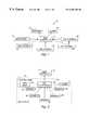
- FIG. 1is a functional block diagram of a security system 10 for use in a building complex having multiple units.
- security system 10includes a main controller 12 , unit systems 14 , 16 , 18 , 20 , 22 , a telephone interface 24 , and an alarm 26 .
- Security system 10is applicable to a variety of building complexes having multiple units including residential building complexes having residential units such as apartments or condominiums, and commercial building complexes having commercial units such as offices, businesses, or storage facilities.
- Unit systems 14 , 16 , 18 , 20 , 22monitor various security conditions within respective units in the building complex.
- Main controller 12operates in a supervisory capacity, communicating with each of unit systems 14 , 16 , 18 , 20 , 22 , or some subset thereof, to monitor the security conditions among the units in the overall building complex.
- Each unit system 14 , 16 , 18 , 20 , 22is associated with one of the units in the building complex, and typically is located within a particular unit.
- security system 10typically will include n unit systems. It is conceivable, however, that a single unit system 14 , 16 , 18 , 20 , 22 could be associated with two or more adjacent units.
- Main controller 12typically will be located remotely from the units monitored by unit systems 14 , 16 , 18 , 20 , 22 .
- main controller 12can be located in a central security or utility room within the complex, or at a site remote from the complex.
- Communication between main controller 12 and unit systems 14 , 16 , 18 , 20 , 22can be wireless or hard-wired depending on the building complex. Wireless communication is preferred, however, for ease of installation as well as reliability of communication. In particular, unlike a hard-wired link, the wireless link cannot be physically severed by an intruder.
- Unit systems 14 , 16 , 18 , 20 , 22monitor security conditions such as intruder entry into the respective units, e.g., by door or window entry or motion detection. The monitored security conditions also may include the presence of fire, smoke, or irregular temperatures within the unit.
- Main controller 12monitors the status of unit systems 14 , 16 , 18 , 20 , 22 , for example, by listening for unit alarm signals transmitted from the unit systems. Alternatively, main controller 12 could be configured to periodically poll the individual unit systems 14 , 16 , 18 , 20 , 22 for unit alarm conditions. If one of unit systems 14 , 16 , 18 , 20 , 22 indicates a security condition, main controller 12 is operative to notify a security agency via interface 24 to the public telephone network.
- main controller 12may send notification to a municipal entity such as the police or fire department, or to a private security service. Also, main controller 12 may be configured to notify a resident of the security condition. Main controller 12 also can be equipped to activate a main alarm 26 . Main alarm 26 may provide audible output, visible output, or a combination of both, and can be located with main controller 12 or at another location within the building complex.
- FIG. 2is a functional block diagram of a unit system 14 for use with security system 10 as shown in FIG. 1 .
- Unit system 14includes a control panel 28 , one or more (1 ⁇ n) sensors 30 , 32 , 34 , 36 , 38 , and a unit alarm 40 .
- Control panel 28 , sensors 30 , 32 , 34 , 36 , 38 , and unit alarm 40ordinarily will be located within a single unit.
- Control panel 28includes a unit controller 42 and a user input device 44 .
- Unit controller 42 and user input device 44are mounted together in control panel 28 , i.e., in a common housing, to conserve space and facilitate installation.
- unit controller 42 and user input device 44conceivably could be housed separately but located adjacent one another.
- Control panel 28can be mounted, for example, on a wall adjacent the main door of the respective unit. In this manner, control panel 28 is readily accessible by a resident upon entry into the unit.
- Each sensor 30 , 32 , 34 , 36 , 38is located within a particular unit to monitor local security conditions within the unit.
- sensors 30 , 32 , 34 , 36 , 38may take the form of door/window entry sensors, motion sensors, fire, smoke, or temperature sensors, or a combination of such sensors.
- Sensors 30 , 32 , 34 , 36 , 38communicate with control panel 28 and, in particular, unit controller 42 by wireless or hardwired communication.
- a respective sensor 30 , 32 , 34 36 , 38communicates an indication of the security condition to unit controller 42 , for example, by transmitting a sensor signal.
- the sensor signaltypically will represent a change in the status of a monitored condition.
- a sensor 30 , 32 , 34 , 36 , 38configured to monitor a door will transmit a sensor signal to unit controller 42 when the door is opened.
- unit controller 42Upon receipt of a sensor signal from one of sensors 30 , 32 , 34 , 36 , 38 , unit controller 42 indicates a unit alarm condition and communicates it to main controller 12 , for example, by transmission of a unit alarm signal.
- the unit alarm signalcan be communicated to main controller 12 by wireless or hardwired communication.
- Telephone communication between unit controller 42 and main controller 12is possible but generally undesirable due to greater difficulty of installation and the possibility that the telephone line for the respective unit could be tied up during an emergency situation. Also, reliance on telephone service can make the unit vulnerable to intrusion during periods of unit vacancy. Hardwired communication links are susceptible to physical tampering, and also are less desirable. Accordingly, it is preferred that unit controller 42 communicate with main controller 12 by wireless radio frequency communication.
- User input device 44accepts user input to invalidate the unit alarm condition.
- unit controller 42communicates with user input device 44 to receive indication of the user input for invalidation of the unit alarm condition.
- User input device 44may take a variety of forms.
- user input device 44could be an alphanumeric keypad that allows entry of a code to indicate invalidation of the unit alarm condition.
- user input device 44could be configured to accept a key that can be turned to indicate invalidation of the unit alarm condition.
- user input devicecould take the form of a radio frequency receiver that receives an invalidating code from a transmitter carried by a unit resident, e.g., on a keychain. In any event, user input device 44 allows the system user to invalidate the unit alarm condition and disarm unit system 14 .
- User input device 44is not capable of preventing unit controller 42 from communicating the unit alarm signal to main controller 12 .
- unit controller 42communicates the unit alarm signal to main controller 12 without significant delay following receipt of a sensor signal.
- unit controller 42transmits the unit alarm signal to main controller 12 within a period of time during which an intruder is capable of obtaining physical access to control panel 28 following entry into the unit.
- unit controller 42communicates the unit alarm signal to main controller 12 substantially immediately following receipt of the sensor signal. In this manner, unit controller 42 is capable of circumventing efforts to disable unit system 14 by damaging control panel 28 . In other words, the unit alarm condition is communicated before the intruder has the chance to disable control panel 28 .
- User input device 44is incapable of preventing the transmission of the unit alarm signal. However, entry of user input into user input device 44 within an entry delay period allows a resident to invalidate the unit alarm signal. Specifically, upon generation of the unit alarm signal, unit controller 42 starts a timer that indicates the elapse of a unit delay period. The unit delay period should be sufficient to allow a typical user to enter the required information into user input device 44 . If an indication of the required user input is received from user input device 44 prior to expiration of the unit delay period, unit controller 42 transmits a unit alarm invalidation signal to main controller 12 .
- main controller 12Upon receipt of the original unit alarm signal, main controller 12 starts a separate timer that indicates the elapse of a main delay period.
- the unit and main delay periodscan be of approximately the same length, but are timed separately by unit controller 42 and main controller 12 , respectively. If the unit alarm invalidation signal is received from unit controller 42 prior to expiration of the main delay period, main controller 12 does not indicate a main alarm condition by generation of a main alarm signal. Consequently, main controller 12 does not notify a security agency of the security condition, nor activate an alarm, as illustrated in FIG. 1 . Instead, main controller 12 invalidates the main alarm, resetting itself to wait for the next unit alarm signal from one of the unit systems 14 , 16 , 18 , 20 , 22 in the building complex. Similarly, upon generation of the unit alarm invalidation signal, unit controller 42 does not activate alarm 40 , and instead resets itself to await a subsequent sensor signal from one of sensors 30 , 32 , 34 , 36 , 38 .
- unit controller 42does not generate the unit alarm invalidation signal. Instead, under ordinary circumstances, unit controller 42 activates alarm 40 , which may be positioned within the unit to provide audible output, visible output, or both. If control panel 28 is destroyed by an intruder, unit controller 42 may be rendered inoperable. In this case, unit controller 42 may be incapable of activating alarm 40 , but also cannot generate the unit alarm invalidation signal. Thus, whether the unit period expires or control panel 28 is destroyed, unit alarm signal has already been sent to main controller 12 . In either case, in the absence of a unit alarm invalidation signal, the main delay period timed by main controller 12 expires. With further reference to FIG.
- main controller 12upon expiration of the main delay period, main controller 12 proceeds on the basis of the unit alarm signal to notify a security agency via telephone interface 24 and activate alarm 26 . Consequently, it is apparent that security system 10 is capable of operating successfully to detect an intruder or other security condition despite the possible efforts of an intruder to disable it by destroying control panel 28 . At the same time, security system 10 allows a resident to enter user input for a period of time following transmission of the original unit alarm signal to disarm unit system 14 .
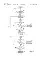
- FIG. 3is a flow diagram illustrating the operation of a unit system 14 as shown in FIG. 2 .
- unit controller 42Upon system initialization, or the start of operation, as represented by block 46 , unit controller 42 begins to listen for sensor signals transmitted from sensors 30 , 32 , 34 , 36 , 38 , as represented by block 48 .
- Unit controller 42continues to listen, as represented by loop 50 , until a sensor signal is received.
- unit controller 42Upon receipt of a sensor signal, unit controller 42 immediately generates a unit alarm signal, as represented by block 52 , and transmits the unit alarm signal to main controller 12 .
- Unit controller 42then starts a timer t 1 , as represented by blocks 54 and 56 .
- unit controller 42compares it to the unit delay period T u , as represented by block 58 . As long as the unit delay period T u has not expired, unit controller 42 continues to listen for user input from user input device 44 , as represented by block 60 and loop 62 . If appropriate user input has not been received prior to expiration of the unit delay period T u , unit controller 42 activates unit alarm 40 within the unit, as represented by block 64 . If user input is received in advance of expiration, however, unit controller 42 invalidates the unit alarm signal, as indicated by block 66 . Unit controller 42 sends the unit alarm invalidation signal to main controller 12 , which resets itself.
- main controller 12Upon receipt of a unit alarm signal from unit controller 42 , as represented by line 67 , main controller 12 starts a timer t 2 , as represented by blocks 68 and 70 . As the timer t 2 is incremented, main controller 12 compares it to the main delay period T m , as represented by block 72 . As long as the unit delay period T m has not expired, main controller 12 continues to listen for the unit alarm invalidation from unit controller 42 , as represented by block 74 and loop 76 .
- main controller 12If the unit alarm invalidation signal has not been received prior to expiration of the main delay period T m , main controller 12 generates a main alarm signal, and proceeds to notify a security agency of the security condition by telephone interface 24 and activate main alarm 26 , as indicated by block 78 . If the unit alarm invalidation signal is received in advance of expiration of the main delay period T m , however, main controller 12 invalidates the main alarm, as indicated by block 80 . In particular, main controller 12 resets itself and listens for the next unit alarm signal to be transmitted by one of unit systems 14 , 16 , 18 , 20 , 22 within the building complex.
Landscapes
- Business, Economics & Management (AREA)
- Emergency Management (AREA)
- Physics & Mathematics (AREA)
- General Physics & Mathematics (AREA)
- Engineering & Computer Science (AREA)
- Computer Networks & Wireless Communication (AREA)
- Alarm Systems (AREA)
- Telephonic Communication Services (AREA)
Abstract
Description
Claims (33)
Priority Applications (1)
| Application Number | Priority Date | Filing Date | Title |
|---|---|---|---|
| US09/238,750US6204760B1 (en) | 1998-01-30 | 1999-01-28 | Security system for a building complex having multiple units |
Applications Claiming Priority (2)
| Application Number | Priority Date | Filing Date | Title |
|---|---|---|---|
| US7317698P | 1998-01-30 | 1998-01-30 | |
| US09/238,750US6204760B1 (en) | 1998-01-30 | 1999-01-28 | Security system for a building complex having multiple units |
Publications (1)
| Publication Number | Publication Date |
|---|---|
| US6204760B1true US6204760B1 (en) | 2001-03-20 |
Family
ID=26754205
Family Applications (1)
| Application Number | Title | Priority Date | Filing Date |
|---|---|---|---|
| US09/238,750Expired - LifetimeUS6204760B1 (en) | 1998-01-30 | 1999-01-28 | Security system for a building complex having multiple units |
Country Status (1)
| Country | Link |
|---|---|
| US (1) | US6204760B1 (en) |
Cited By (66)
| Publication number | Priority date | Publication date | Assignee | Title |
|---|---|---|---|---|
| US20020087867A1 (en)* | 2000-11-28 | 2002-07-04 | Oberle Robert R. | RF ID card |
| US20020145506A1 (en)* | 2001-04-09 | 2002-10-10 | Takayuki Sato | Multi-unit building with secure entry system |
| US20020163430A1 (en)* | 2001-05-01 | 2002-11-07 | Bergman John Todd | Wireless phone-interface device |
| US6636150B2 (en)* | 1997-04-16 | 2003-10-21 | A L Air Data Inc | Lamp monitoring and control system and method |
| US20030218533A1 (en)* | 2002-05-22 | 2003-11-27 | Flick Kenneth E. | Door access control system and associated methods |
| US20030227540A1 (en)* | 2002-06-05 | 2003-12-11 | Monroe David A. | Emergency telephone with integrated surveillance system connectivity |
| US6664894B2 (en)* | 2001-02-16 | 2003-12-16 | General Phosphorix Llc | Perimeter system for detecting intruders |
| US20040075347A1 (en)* | 2000-08-04 | 2004-04-22 | Energy Technologies Group, Llc | Security and energy control system and method |
| US20040124976A1 (en)* | 2002-09-12 | 2004-07-01 | Nambi Seshadri | Detecting communications disconnect and enabling wireless emergency call |
| US20040151282A1 (en)* | 2002-05-22 | 2004-08-05 | Jones Russell K. | Condition detection and notification systems and methods |
| US20040150521A1 (en)* | 2003-02-03 | 2004-08-05 | Stilp Louis A. | RFID based security system |
| US20040160324A1 (en)* | 2003-02-03 | 2004-08-19 | Stilp Louis A. | Controller for a security system |
| US20040160323A1 (en)* | 2003-02-03 | 2004-08-19 | Stilp Louis A. | RFID transponder for a security system |
| US20040160309A1 (en)* | 2003-02-03 | 2004-08-19 | Stilp Louis A. | Communications control in a security system |
| US20040160322A1 (en)* | 2003-02-03 | 2004-08-19 | Stilp Louis A. | RFID reader for a security system |
| US20040160306A1 (en)* | 2003-02-03 | 2004-08-19 | Stilp Louis A. | Device enrollment in a security system |
| US20040215750A1 (en)* | 2003-04-28 | 2004-10-28 | Stilp Louis A. | Configuration program for a security system |
| US20040212494A1 (en)* | 2003-02-03 | 2004-10-28 | Stilp Louis A. | Cordless telephone system |
| US20040212493A1 (en)* | 2003-02-03 | 2004-10-28 | Stilp Louis A. | RFID reader for a security network |
| US20040212497A1 (en)* | 2003-02-03 | 2004-10-28 | Stilp Louis A. | Multi-controller security network |
| US20040212500A1 (en)* | 2003-02-03 | 2004-10-28 | Stilp Louis A. | RFID based security network |
| WO2004114244A1 (en)* | 2003-06-25 | 2004-12-29 | Han-Gyu Yang | Disaster preventing system using digital radio communication |
| US20050017727A1 (en)* | 2003-05-06 | 2005-01-27 | Rcd Technology, Inc. | Radio frequency identification sensor for fluid level |
| US20050253772A1 (en)* | 2000-03-13 | 2005-11-17 | Rcd Technology Corp. | Method for forming radio frequency antenna |
| US20060028379A1 (en)* | 2000-03-13 | 2006-02-09 | Rcd Technology Corp. | Method for forming radio frequency antenna |
| US20060097842A1 (en)* | 2002-06-13 | 2006-05-11 | Michel Gielis | Controlling and/or monitoring device using at least a transmission controller |
| US7054414B2 (en) | 2001-05-01 | 2006-05-30 | Interactive Technologies Inc. | Wireless phone-interface device |
| US20060132302A1 (en)* | 2003-02-03 | 2006-06-22 | Stilp Louis A | Power management of transponders and sensors in an RFID security network |
| US20060132303A1 (en)* | 2003-02-03 | 2006-06-22 | Stilp Louis A | Component diversity in a RFID security network |
| US20060132301A1 (en)* | 2003-02-03 | 2006-06-22 | Stilp Louis A | Fixed part-portable part communications network for a security network |
| US20060145842A1 (en)* | 2003-02-03 | 2006-07-06 | Stilp Louis A | Multi-level meshed security network |
| US20060205113A1 (en)* | 2005-03-14 | 2006-09-14 | Rcd Technology Corp. | Radio frequency identification (RFID) tag lamination process |
| US20060205115A1 (en)* | 2005-03-14 | 2006-09-14 | Rcd Technology Corp. | Radio frequency identification (RFID) tag lamination process using liner |
| US20060227001A1 (en)* | 2005-04-11 | 2006-10-12 | Dennis Petricoin | Method and apparatus for providing graduated annunciation of an impending alarm in a security system |
| US20070021946A1 (en)* | 1997-04-16 | 2007-01-25 | A.L. Air Data, Inc. | Lamp monitoring and control unit and method |
| US20070032990A1 (en)* | 1997-04-16 | 2007-02-08 | A. L. Air Data, Inc. | Lamp monitoring and control system and method |
| US20070103379A1 (en)* | 2005-11-10 | 2007-05-10 | Garby Sandra M | Method for an element using two resist layers |
| US20070125867A1 (en)* | 2005-12-05 | 2007-06-07 | Rcd Technology Corp. | Tuned radio frequency identification (RFID) circuit used as a security device for wristbands and package security |
| US7268740B2 (en) | 2000-03-13 | 2007-09-11 | Rcd Technology Inc. | Method for forming radio frequency antenna |
| US20080001734A1 (en)* | 2003-02-03 | 2008-01-03 | Stilp Louis A | Portable telephone in a security network |
| WO2008014669A1 (en)* | 2006-07-27 | 2008-02-07 | Zhihao Wen | A security monitoring system |
| US20080117064A1 (en)* | 2006-06-29 | 2008-05-22 | Jeong-Hun Shin | Fire detector having a lifting function |
| US20080129444A1 (en)* | 2006-12-01 | 2008-06-05 | Shary Nassimi | Wireless Security System |
| US20080129455A1 (en)* | 2006-05-24 | 2008-06-05 | Rcd Technology Inc. | Method for forming rfid tags |
| US20080144834A1 (en)* | 2004-04-30 | 2008-06-19 | Steven Barnett Rakoff | Security System Communications Including Encryption |
| US20100026487A1 (en)* | 2006-05-04 | 2010-02-04 | Shmuel Hershkovitz | Security system control panel |
| US20100097210A1 (en)* | 2008-10-17 | 2010-04-22 | Honeywell International Inc. | Wireless interface device allowing a reliable digital and audio communication transfer between a security system, pots and/or ip network modem device |
| US20100283608A1 (en)* | 2007-01-04 | 2010-11-11 | Honeywell International Inc. | Intrusion Warning and Reporting Network |
| US20110037593A1 (en)* | 2009-08-14 | 2011-02-17 | Tyco Safety Products Canada Ltd. | Security system annunciation communication delay |
| US20110201298A1 (en)* | 2010-02-18 | 2011-08-18 | Jerome Gelover | Substitution of a telephone land line based home alarm system with a cell phone connection based system |
| US20120133511A1 (en)* | 2010-11-29 | 2012-05-31 | Honeywell International Inc. | Method and apparatus for detecting control panel attacks in a security system |
| US20120286947A1 (en)* | 2011-05-09 | 2012-11-15 | Tau-Jeng Hsu | Home security system |
| US20130147627A1 (en)* | 2010-05-19 | 2013-06-13 | Vcfire System Ab | Fire monitoring system |
| US20130278410A1 (en)* | 2012-04-20 | 2013-10-24 | Numerex Corp. | System and Method for Using Alarm System Zones for Remote Objects |
| US20140094354A1 (en)* | 2012-10-02 | 2014-04-03 | Joe Augustine S.T. Lam | Tape monitoring system |
| US9142118B2 (en) | 2007-08-03 | 2015-09-22 | Belkin International, Inc. | Emergency notification device and system |
| WO2015191722A1 (en)* | 2014-06-13 | 2015-12-17 | Vivint, Inc. | Detecting a premise condition using audio analytics |
| US9454882B2 (en) | 2014-06-26 | 2016-09-27 | Vivint, Inc. | Verifying occupancy of a building |
| US20170115017A1 (en)* | 2004-11-18 | 2017-04-27 | Ubiquitous Connectivity, Lp | Ubiquitous connectivity and control system for remote locations |
| US9741221B1 (en)* | 2014-06-30 | 2017-08-22 | Intrusion Technologies, LLC | Active intruder mitigation system and method |
| US10152876B2 (en) | 1996-03-27 | 2018-12-11 | Gtj Ventures, Llc | Control, monitoring, and/or security apparatus and method |
| EP3598404A1 (en)* | 2018-07-16 | 2020-01-22 | Verisure Sàrl | A method of operating an alarm system for a building, alarm system for a building and alarm installation |
| US10546441B2 (en) | 2013-06-04 | 2020-01-28 | Raymond Anthony Joao | Control, monitoring, and/or security, apparatus and method for premises, vehicles, and/or articles |
| US10562492B2 (en) | 2002-05-01 | 2020-02-18 | Gtj Ventures, Llc | Control, monitoring and/or security apparatus and method |
| US10796268B2 (en) | 2001-01-23 | 2020-10-06 | Gtj Ventures, Llc | Apparatus and method for providing shipment information |
| US10922935B2 (en) | 2014-06-13 | 2021-02-16 | Vivint, Inc. | Detecting a premise condition using audio analytics |
Citations (22)
| Publication number | Priority date | Publication date | Assignee | Title |
|---|---|---|---|---|
| US4023139A (en) | 1974-10-24 | 1977-05-10 | Gene Samburg | Security control and alarm system |
| US4114147A (en)* | 1977-03-24 | 1978-09-12 | Hile John R | Code combination property alarm system |
| US4148019A (en) | 1975-03-05 | 1979-04-03 | Thomas Industries Inc. | Security alarm transmission system |
| US4228424A (en)* | 1978-10-16 | 1980-10-14 | Baker Protective Services, Incorporated | Central station alarm |
| US4375637A (en) | 1981-02-24 | 1983-03-01 | Firecom, Inc. | Integrated alarm, security, building management, and communications system |
| US4408251A (en) | 1981-07-13 | 1983-10-04 | Spectrum Four-Syte Corporation | Tamper-resistant security system for and method of operating and installing same |
| US4465904A (en)* | 1978-09-29 | 1984-08-14 | Gottsegen Ronald B | Programmable alarm system |
| US4661804A (en) | 1982-09-30 | 1987-04-28 | Sentrol, Inc. | Supervised wireless security system |
| US4667183A (en)* | 1985-09-09 | 1987-05-19 | Napco Security Systems, Inc. | Keyboard hold-down functions for a multi-zone intrusion detection system |
| US4721954A (en) | 1985-12-18 | 1988-01-26 | Marlee Electronics Corporation | Keypad security system |
| US4754261A (en) | 1987-03-30 | 1988-06-28 | Pittway Corporation | Security system |
| US4760393A (en) | 1985-12-18 | 1988-07-26 | Marlee Electronics Corporation | Security entry system |
| US4855713A (en) | 1988-10-07 | 1989-08-08 | Interactive Technologies, Inc. | Learn mode transmitter |
| US4908604A (en)* | 1987-09-21 | 1990-03-13 | Dimango Products Corporation | Remotely controlled security system |
| US4937855A (en) | 1988-02-09 | 1990-06-26 | Viscount Industries Limited | Building security system |
| US4951029A (en) | 1988-02-16 | 1990-08-21 | Interactive Technologies, Inc. | Micro-programmable security system |
| US5499014A (en) | 1994-07-01 | 1996-03-12 | Greenwaldt; Gordon E. | Security alarm system |
| US5598456A (en) | 1993-06-23 | 1997-01-28 | Feinberg; David H. | Integrated telephone, intercom, security and control system for a multi-unit building |
| US5625338A (en) | 1993-12-16 | 1997-04-29 | Digital Security Controls Ltd. | Wireless alarm system |
| US5737391A (en) | 1995-09-06 | 1998-04-07 | Richard J. Dame | Alarm system backup with cut line detector |
| US5805063A (en) | 1996-02-09 | 1998-09-08 | Interactive Technologies, Inc. | Wireless security sensor transmitter |
| US5809013A (en) | 1996-02-09 | 1998-09-15 | Interactive Technologies, Inc. | Message packet management in a wireless security system |
- 1999
- 1999-01-28USUS09/238,750patent/US6204760B1/ennot_activeExpired - Lifetime
Patent Citations (22)
| Publication number | Priority date | Publication date | Assignee | Title |
|---|---|---|---|---|
| US4023139A (en) | 1974-10-24 | 1977-05-10 | Gene Samburg | Security control and alarm system |
| US4148019A (en) | 1975-03-05 | 1979-04-03 | Thomas Industries Inc. | Security alarm transmission system |
| US4114147A (en)* | 1977-03-24 | 1978-09-12 | Hile John R | Code combination property alarm system |
| US4465904A (en)* | 1978-09-29 | 1984-08-14 | Gottsegen Ronald B | Programmable alarm system |
| US4228424A (en)* | 1978-10-16 | 1980-10-14 | Baker Protective Services, Incorporated | Central station alarm |
| US4375637A (en) | 1981-02-24 | 1983-03-01 | Firecom, Inc. | Integrated alarm, security, building management, and communications system |
| US4408251A (en) | 1981-07-13 | 1983-10-04 | Spectrum Four-Syte Corporation | Tamper-resistant security system for and method of operating and installing same |
| US4661804A (en) | 1982-09-30 | 1987-04-28 | Sentrol, Inc. | Supervised wireless security system |
| US4667183A (en)* | 1985-09-09 | 1987-05-19 | Napco Security Systems, Inc. | Keyboard hold-down functions for a multi-zone intrusion detection system |
| US4760393A (en) | 1985-12-18 | 1988-07-26 | Marlee Electronics Corporation | Security entry system |
| US4721954A (en) | 1985-12-18 | 1988-01-26 | Marlee Electronics Corporation | Keypad security system |
| US4754261A (en) | 1987-03-30 | 1988-06-28 | Pittway Corporation | Security system |
| US4908604A (en)* | 1987-09-21 | 1990-03-13 | Dimango Products Corporation | Remotely controlled security system |
| US4937855A (en) | 1988-02-09 | 1990-06-26 | Viscount Industries Limited | Building security system |
| US4951029A (en) | 1988-02-16 | 1990-08-21 | Interactive Technologies, Inc. | Micro-programmable security system |
| US4855713A (en) | 1988-10-07 | 1989-08-08 | Interactive Technologies, Inc. | Learn mode transmitter |
| US5598456A (en) | 1993-06-23 | 1997-01-28 | Feinberg; David H. | Integrated telephone, intercom, security and control system for a multi-unit building |
| US5625338A (en) | 1993-12-16 | 1997-04-29 | Digital Security Controls Ltd. | Wireless alarm system |
| US5499014A (en) | 1994-07-01 | 1996-03-12 | Greenwaldt; Gordon E. | Security alarm system |
| US5737391A (en) | 1995-09-06 | 1998-04-07 | Richard J. Dame | Alarm system backup with cut line detector |
| US5805063A (en) | 1996-02-09 | 1998-09-08 | Interactive Technologies, Inc. | Wireless security sensor transmitter |
| US5809013A (en) | 1996-02-09 | 1998-09-15 | Interactive Technologies, Inc. | Message packet management in a wireless security system |
Cited By (113)
| Publication number | Priority date | Publication date | Assignee | Title |
|---|---|---|---|---|
| US10152876B2 (en) | 1996-03-27 | 2018-12-11 | Gtj Ventures, Llc | Control, monitoring, and/or security apparatus and method |
| US6636150B2 (en)* | 1997-04-16 | 2003-10-21 | A L Air Data Inc | Lamp monitoring and control system and method |
| US20070032990A1 (en)* | 1997-04-16 | 2007-02-08 | A. L. Air Data, Inc. | Lamp monitoring and control system and method |
| US20070021946A1 (en)* | 1997-04-16 | 2007-01-25 | A.L. Air Data, Inc. | Lamp monitoring and control unit and method |
| US20060028379A1 (en)* | 2000-03-13 | 2006-02-09 | Rcd Technology Corp. | Method for forming radio frequency antenna |
| US20050253772A1 (en)* | 2000-03-13 | 2005-11-17 | Rcd Technology Corp. | Method for forming radio frequency antenna |
| US7268740B2 (en) | 2000-03-13 | 2007-09-11 | Rcd Technology Inc. | Method for forming radio frequency antenna |
| US7298331B2 (en) | 2000-03-13 | 2007-11-20 | Rcd Technology, Inc. | Method for forming radio frequency antenna |
| US20070273605A1 (en)* | 2000-03-13 | 2007-11-29 | Rcd Technology Inc. | Method for forming radio frequency antenna |
| US7515116B2 (en) | 2000-03-13 | 2009-04-07 | Rcd Technology, Inc. | Method for forming radio frequency antenna |
| US7639184B2 (en) | 2000-03-13 | 2009-12-29 | Rcd Technology Inc. | Method for forming radio frequency antenna |
| US20040075347A1 (en)* | 2000-08-04 | 2004-04-22 | Energy Technologies Group, Llc | Security and energy control system and method |
| US20070024125A1 (en)* | 2000-08-04 | 2007-02-01 | Energy Technologies Group, Llc | Security and energy control system and method |
| US7868734B2 (en) | 2000-08-04 | 2011-01-11 | Energy Technologies Group, LLC. | Security and energy control system and method |
| US7138732B2 (en)* | 2000-08-04 | 2006-11-21 | Energy Technologies, L.L.C. | Security and energy control system and method |
| US20020087867A1 (en)* | 2000-11-28 | 2002-07-04 | Oberle Robert R. | RF ID card |
| US10796268B2 (en) | 2001-01-23 | 2020-10-06 | Gtj Ventures, Llc | Apparatus and method for providing shipment information |
| US6664894B2 (en)* | 2001-02-16 | 2003-12-16 | General Phosphorix Llc | Perimeter system for detecting intruders |
| US20020145506A1 (en)* | 2001-04-09 | 2002-10-10 | Takayuki Sato | Multi-unit building with secure entry system |
| US6961771B2 (en)* | 2001-04-09 | 2005-11-01 | Allied Telesis K.K. | Multi-unit building with secure entry system |
| US7054414B2 (en) | 2001-05-01 | 2006-05-30 | Interactive Technologies Inc. | Wireless phone-interface device |
| US7248157B2 (en) | 2001-05-01 | 2007-07-24 | Interactive Technologies, Inc. | Wireless phone-interface device |
| US20020163430A1 (en)* | 2001-05-01 | 2002-11-07 | Bergman John Todd | Wireless phone-interface device |
| US10562492B2 (en) | 2002-05-01 | 2020-02-18 | Gtj Ventures, Llc | Control, monitoring and/or security apparatus and method |
| US20030218533A1 (en)* | 2002-05-22 | 2003-11-27 | Flick Kenneth E. | Door access control system and associated methods |
| US6850601B2 (en) | 2002-05-22 | 2005-02-01 | Sentinel Vision, Inc. | Condition detection and notification systems and methods |
| US20040151282A1 (en)* | 2002-05-22 | 2004-08-05 | Jones Russell K. | Condition detection and notification systems and methods |
| US20030227540A1 (en)* | 2002-06-05 | 2003-12-11 | Monroe David A. | Emergency telephone with integrated surveillance system connectivity |
| US7428002B2 (en) | 2002-06-05 | 2008-09-23 | Monroe David A | Emergency telephone with integrated surveillance system connectivity |
| US7486169B2 (en)* | 2002-06-13 | 2009-02-03 | Inventio Ag | Controlling and/or monitoring device using at least a transmission controller |
| US20060097842A1 (en)* | 2002-06-13 | 2006-05-11 | Michel Gielis | Controlling and/or monitoring device using at least a transmission controller |
| US20040124976A1 (en)* | 2002-09-12 | 2004-07-01 | Nambi Seshadri | Detecting communications disconnect and enabling wireless emergency call |
| US7053768B2 (en)* | 2002-09-12 | 2006-05-30 | Broadcom Corporation | Detecting communications disconnect and enabling wireless emergency call |
| US7019639B2 (en) | 2003-02-03 | 2006-03-28 | Ingrid, Inc. | RFID based security network |
| US6888459B2 (en)* | 2003-02-03 | 2005-05-03 | Louis A. Stilp | RFID based security system |
| US7057512B2 (en) | 2003-02-03 | 2006-06-06 | Ingrid, Inc. | RFID reader for a security system |
| US20060132302A1 (en)* | 2003-02-03 | 2006-06-22 | Stilp Louis A | Power management of transponders and sensors in an RFID security network |
| US20060132303A1 (en)* | 2003-02-03 | 2006-06-22 | Stilp Louis A | Component diversity in a RFID security network |
| US20060132301A1 (en)* | 2003-02-03 | 2006-06-22 | Stilp Louis A | Fixed part-portable part communications network for a security network |
| US20060145842A1 (en)* | 2003-02-03 | 2006-07-06 | Stilp Louis A | Multi-level meshed security network |
| US7079020B2 (en) | 2003-02-03 | 2006-07-18 | Ingrid, Inc. | Multi-controller security network |
| US7079034B2 (en) | 2003-02-03 | 2006-07-18 | Ingrid, Inc. | RFID transponder for a security system |
| US7084756B2 (en) | 2003-02-03 | 2006-08-01 | Ingrid, Inc. | Communications architecture for a security network |
| US7091827B2 (en) | 2003-02-03 | 2006-08-15 | Ingrid, Inc. | Communications control in a security system |
| US20040160322A1 (en)* | 2003-02-03 | 2004-08-19 | Stilp Louis A. | RFID reader for a security system |
| US7532114B2 (en) | 2003-02-03 | 2009-05-12 | Ingrid, Inc. | Fixed part-portable part communications network for a security network |
| US7119658B2 (en) | 2003-02-03 | 2006-10-10 | Ingrid, Inc. | Device enrollment in a security system |
| US20040160306A1 (en)* | 2003-02-03 | 2004-08-19 | Stilp Louis A. | Device enrollment in a security system |
| US7042353B2 (en) | 2003-02-03 | 2006-05-09 | Ingrid, Inc. | Cordless telephone system |
| US7023341B2 (en) | 2003-02-03 | 2006-04-04 | Ingrid, Inc. | RFID reader for a security network |
| US20040212494A1 (en)* | 2003-02-03 | 2004-10-28 | Stilp Louis A. | Cordless telephone system |
| US20040160309A1 (en)* | 2003-02-03 | 2004-08-19 | Stilp Louis A. | Communications control in a security system |
| US7202789B1 (en) | 2003-02-03 | 2007-04-10 | Ingrid, Inc. | Clip for RFID transponder of a security network |
| US7053764B2 (en) | 2003-02-03 | 2006-05-30 | Ingrid, Inc. | Controller for a security system |
| US20040150521A1 (en)* | 2003-02-03 | 2004-08-05 | Stilp Louis A. | RFID based security system |
| US7495544B2 (en) | 2003-02-03 | 2009-02-24 | Ingrid, Inc. | Component diversity in a RFID security network |
| US20040212500A1 (en)* | 2003-02-03 | 2004-10-28 | Stilp Louis A. | RFID based security network |
| US7283048B2 (en) | 2003-02-03 | 2007-10-16 | Ingrid, Inc. | Multi-level meshed security network |
| US20040212497A1 (en)* | 2003-02-03 | 2004-10-28 | Stilp Louis A. | Multi-controller security network |
| US20040212493A1 (en)* | 2003-02-03 | 2004-10-28 | Stilp Louis A. | RFID reader for a security network |
| US20080001734A1 (en)* | 2003-02-03 | 2008-01-03 | Stilp Louis A | Portable telephone in a security network |
| US20040160324A1 (en)* | 2003-02-03 | 2004-08-19 | Stilp Louis A. | Controller for a security system |
| US7511614B2 (en) | 2003-02-03 | 2009-03-31 | Ingrid, Inc. | Portable telephone in a security network |
| US20040160323A1 (en)* | 2003-02-03 | 2004-08-19 | Stilp Louis A. | RFID transponder for a security system |
| US20040215750A1 (en)* | 2003-04-28 | 2004-10-28 | Stilp Louis A. | Configuration program for a security system |
| US20050017727A1 (en)* | 2003-05-06 | 2005-01-27 | Rcd Technology, Inc. | Radio frequency identification sensor for fluid level |
| US7456752B2 (en) | 2003-05-06 | 2008-11-25 | Rcd Technology, Inc. | Radio frequency identification sensor for fluid level |
| WO2004114244A1 (en)* | 2003-06-25 | 2004-12-29 | Han-Gyu Yang | Disaster preventing system using digital radio communication |
| US20080144834A1 (en)* | 2004-04-30 | 2008-06-19 | Steven Barnett Rakoff | Security System Communications Including Encryption |
| US20170115017A1 (en)* | 2004-11-18 | 2017-04-27 | Ubiquitous Connectivity, Lp | Ubiquitous connectivity and control system for remote locations |
| US10344999B2 (en)* | 2004-11-18 | 2019-07-09 | Ubiquitous Connectivity, Lp | Ubiquitous connectivity and control system for remote locations |
| US7674649B2 (en) | 2005-03-14 | 2010-03-09 | Rcd Technology Inc. | Radio frequency identification (RFID) tag lamination process using liner |
| US7456506B2 (en) | 2005-03-14 | 2008-11-25 | Rcd Technology Inc. | Radio frequency identification (RFID) tag lamination process using liner |
| US20080311704A1 (en)* | 2005-03-14 | 2008-12-18 | Rcd Technology, Inc. | Radio frequency identification (rfid) tag lamination process using liner |
| US20060205115A1 (en)* | 2005-03-14 | 2006-09-14 | Rcd Technology Corp. | Radio frequency identification (RFID) tag lamination process using liner |
| US20060205113A1 (en)* | 2005-03-14 | 2006-09-14 | Rcd Technology Corp. | Radio frequency identification (RFID) tag lamination process |
| US8264346B2 (en)* | 2005-04-11 | 2012-09-11 | Robert Bosch Gmbh | Method and apparatus for providing graduated annunciation of an impending alarm in a security system |
| US20060227001A1 (en)* | 2005-04-11 | 2006-10-12 | Dennis Petricoin | Method and apparatus for providing graduated annunciation of an impending alarm in a security system |
| US20070103379A1 (en)* | 2005-11-10 | 2007-05-10 | Garby Sandra M | Method for an element using two resist layers |
| US7388542B2 (en) | 2005-11-10 | 2008-06-17 | Rcd Technology, Inc. | Method for an element using two resist layers |
| US20070125867A1 (en)* | 2005-12-05 | 2007-06-07 | Rcd Technology Corp. | Tuned radio frequency identification (RFID) circuit used as a security device for wristbands and package security |
| US7377447B2 (en) | 2005-12-05 | 2008-05-27 | Rcd Technology, Inc. | Tuned radio frequency identification (RFID) circuit used as a security device for wristbands and package security |
| US20100026487A1 (en)* | 2006-05-04 | 2010-02-04 | Shmuel Hershkovitz | Security system control panel |
| US20080129455A1 (en)* | 2006-05-24 | 2008-06-05 | Rcd Technology Inc. | Method for forming rfid tags |
| US20080117064A1 (en)* | 2006-06-29 | 2008-05-22 | Jeong-Hun Shin | Fire detector having a lifting function |
| WO2008014669A1 (en)* | 2006-07-27 | 2008-02-07 | Zhihao Wen | A security monitoring system |
| US20080129444A1 (en)* | 2006-12-01 | 2008-06-05 | Shary Nassimi | Wireless Security System |
| US20100283608A1 (en)* | 2007-01-04 | 2010-11-11 | Honeywell International Inc. | Intrusion Warning and Reporting Network |
| US9142118B2 (en) | 2007-08-03 | 2015-09-22 | Belkin International, Inc. | Emergency notification device and system |
| US9049307B2 (en)* | 2008-10-17 | 2015-06-02 | Honeywell International Inc. | Wireless interface device allowing a reliable digital and audio communication transfer between a security system, POTS and/or IP network modem device |
| US20100097210A1 (en)* | 2008-10-17 | 2010-04-22 | Honeywell International Inc. | Wireless interface device allowing a reliable digital and audio communication transfer between a security system, pots and/or ip network modem device |
| US8368532B2 (en) | 2009-08-14 | 2013-02-05 | Tyco Safety Products Canada Ltd. | Security system annunciation communication delay |
| US20110037593A1 (en)* | 2009-08-14 | 2011-02-17 | Tyco Safety Products Canada Ltd. | Security system annunciation communication delay |
| US20110201298A1 (en)* | 2010-02-18 | 2011-08-18 | Jerome Gelover | Substitution of a telephone land line based home alarm system with a cell phone connection based system |
| US20130147627A1 (en)* | 2010-05-19 | 2013-06-13 | Vcfire System Ab | Fire monitoring system |
| US20120133511A1 (en)* | 2010-11-29 | 2012-05-31 | Honeywell International Inc. | Method and apparatus for detecting control panel attacks in a security system |
| US8421624B2 (en)* | 2011-05-09 | 2013-04-16 | Tau-Jeng Hsu | Home security system |
| US20120286947A1 (en)* | 2011-05-09 | 2012-11-15 | Tau-Jeng Hsu | Home security system |
| US9041527B2 (en)* | 2012-04-20 | 2015-05-26 | Numerex Corp. | System and method for using alarm system zones for remote objects |
| US20130278410A1 (en)* | 2012-04-20 | 2013-10-24 | Numerex Corp. | System and Method for Using Alarm System Zones for Remote Objects |
| US20150254966A1 (en)* | 2012-04-20 | 2015-09-10 | Numerex Corp. | System and Method for Using Alarm System Zones for Remote Objects |
| US9824575B2 (en)* | 2012-04-20 | 2017-11-21 | Numerex Corp. | System and method for using alarm system zones for remote or mobile objects |
| US9102493B2 (en)* | 2012-10-02 | 2015-08-11 | Lamus Enterprises Inc | Tape monitoring system |
| US20140094354A1 (en)* | 2012-10-02 | 2014-04-03 | Joe Augustine S.T. Lam | Tape monitoring system |
| US10546441B2 (en) | 2013-06-04 | 2020-01-28 | Raymond Anthony Joao | Control, monitoring, and/or security, apparatus and method for premises, vehicles, and/or articles |
| WO2015191722A1 (en)* | 2014-06-13 | 2015-12-17 | Vivint, Inc. | Detecting a premise condition using audio analytics |
| US10922935B2 (en) | 2014-06-13 | 2021-02-16 | Vivint, Inc. | Detecting a premise condition using audio analytics |
| US10026282B2 (en) | 2014-06-26 | 2018-07-17 | Vivint, Inc. | Verifying occupancy of a building |
| US9454882B2 (en) | 2014-06-26 | 2016-09-27 | Vivint, Inc. | Verifying occupancy of a building |
| US10522012B1 (en) | 2014-06-26 | 2019-12-31 | Vivint, Inc. | Verifying occupancy of a building |
| US9741221B1 (en)* | 2014-06-30 | 2017-08-22 | Intrusion Technologies, LLC | Active intruder mitigation system and method |
| EP3598404A1 (en)* | 2018-07-16 | 2020-01-22 | Verisure Sàrl | A method of operating an alarm system for a building, alarm system for a building and alarm installation |
| EP4177858A1 (en)* | 2018-07-16 | 2023-05-10 | Verisure Sàrl | Control unit for an alarm system |
Similar Documents
| Publication | Publication Date | Title |
|---|---|---|
| US6204760B1 (en) | Security system for a building complex having multiple units | |
| US11688274B2 (en) | System and method for alarm signaling during alarm system destruction | |
| US7916018B2 (en) | Wireless door contact sensor with motion sensor disable | |
| EP1686551A2 (en) | Exit arming delay security system and method | |
| US8274385B2 (en) | Method and apparatus for controlling the timing of an alarm signal in a security system | |
| US4970494A (en) | Radio controlled home security system | |
| US20060012472A1 (en) | Method for remotely changing the sensitivity of a wireless sensor | |
| GB2220779A (en) | Automated neighboorhood security system | |
| JP4035010B2 (en) | Security device and security system | |
| KR100440660B1 (en) | Wireless type door rock system having a security function | |
| US20120235803A1 (en) | Security system having a vehicle glass breakage alarm | |
| RU2267814C1 (en) | Alarm signaling system for protection of real estate objects | |
| EP1793354B1 (en) | Security system utilizing sequence signal | |
| JP3483247B2 (en) | Wireless monitoring system | |
| KR100332829B1 (en) | Wireless Control System for Prevention of crimes | |
| GB2484462A (en) | Intruder alarm system power supply having a remote communication means associated therewith | |
| JPH11134583A (en) | Multiple dwelling house lobby interphone | |
| KR200254696Y1 (en) | A security system for an apartment house | |
| JPH09198591A (en) | Reporting device for burglary prevention | |
| Zwirn | ALARM DESIGN THAT RINGS TRUE In designing alarm systems, consultants and end users often forget to consider the basics-such as how the system can be defeated | |
| KR20030008870A (en) | The Home Security System and control means | |
| KR20030039821A (en) | A remote control security system with the internet | |
| AU2005323462A1 (en) | Method for remotely changing the sensitivity of a wireless sensor | |
| KR20040047040A (en) | Crime prevention system of entrance door | |
| JPH0334099A (en) | Alarm system for multiple dwelling house and the like |
Legal Events
| Date | Code | Title | Description |
|---|---|---|---|
| AS | Assignment | Owner name:INTERACTIVE TECHNOLOGIES, INC., MINNESOTA Free format text:ASSIGNMENT OF ASSIGNORS INTEREST;ASSIGNOR:BRUNIUS, ROBERT;REEL/FRAME:011049/0658 Effective date:19990318 | |
| FEPP | Fee payment procedure | Free format text:PAYOR NUMBER ASSIGNED (ORIGINAL EVENT CODE: ASPN); ENTITY STATUS OF PATENT OWNER: LARGE ENTITY | |
| REMI | Maintenance fee reminder mailed | ||
| REIN | Reinstatement after maintenance fee payment confirmed | ||
| FP | Lapsed due to failure to pay maintenance fee | Effective date:20050320 | |
| FEPP | Fee payment procedure | Free format text:PETITION RELATED TO MAINTENANCE FEES FILED (ORIGINAL EVENT CODE: PMFP); ENTITY STATUS OF PATENT OWNER: LARGE ENTITY | |
| FEPP | Fee payment procedure | Free format text:PETITION RELATED TO MAINTENANCE FEES GRANTED (ORIGINAL EVENT CODE: PMFG); ENTITY STATUS OF PATENT OWNER: LARGE ENTITY | |
| FPAY | Fee payment | Year of fee payment:4 | |
| PRDP | Patent reinstated due to the acceptance of a late maintenance fee | Effective date:20060921 | |
| STCF | Information on status: patent grant | Free format text:PATENTED CASE | |
| FPAY | Fee payment | Year of fee payment:8 | |
| AS | Assignment | Owner name:GE INTERLOGIX, INC., TEXAS Free format text:MERGER;ASSIGNOR:INTERACTIVE TECHNOLOGIES, INC.;REEL/FRAME:022951/0589 Effective date:20021231 Owner name:GE SECURITY, INC., TEXAS Free format text:CHANGE OF NAME;ASSIGNOR:GE INTERLOGIX, INC.;REEL/FRAME:022960/0020 Effective date:20040120 | |
| FPAY | Fee payment | Year of fee payment:12 | |
| AS | Assignment | Owner name:CARRIER FIRE & SECURITY AMERCIAS CORPORATION, FLORIDA Free format text:CHANGE OF NAME;ASSIGNOR:UTC FIRE & SECURITY AMERICAS CORPORATION, INC.;REEL/FRAME:058740/0596 Effective date:20201001 Owner name:UTC FIRE & SECURITY AMERICAS CORPORATION, INC., FLORIDA Free format text:CHANGE OF NAME;ASSIGNOR:GE SECURITY, INC.;REEL/FRAME:058740/0571 Effective date:20100104 |