US6203539B1 - Method and system for laser treatment of refractive errors using offset imaging - Google Patents
Method and system for laser treatment of refractive errors using offset imagingDownload PDFInfo
- Publication number
- US6203539B1 US6203539B1US08/968,380US96838097AUS6203539B1US 6203539 B1US6203539 B1US 6203539B1US 96838097 AUS96838097 AUS 96838097AUS 6203539 B1US6203539 B1US 6203539B1
- Authority
- US
- United States
- Prior art keywords
- slit
- scanning
- profiled beam
- profiled
- rotation
- Prior art date
- Legal status (The legal status is an assumption and is not a legal conclusion. Google has not performed a legal analysis and makes no representation as to the accuracy of the status listed.)
- Expired - Lifetime
Links
- 238000000034methodMethods0.000titleclaimsabstractdescription92
- 238000003384imaging methodMethods0.000titleclaimsdescription18
- 208000014733refractive errorDiseases0.000titledescription5
- 238000013532laser treatmentMethods0.000titledescription2
- 238000002679ablationMethods0.000claimsabstractdescription60
- 238000011282treatmentMethods0.000claimsabstractdescription39
- 238000001356surgical procedureMethods0.000claimsabstractdescription17
- 238000006073displacement reactionMethods0.000claimsabstractdescription14
- 238000012937correctionMethods0.000claimsdescription49
- 230000003287optical effectEffects0.000claimsdescription48
- 230000007704transitionEffects0.000claimsdescription38
- 210000004087corneaAnatomy0.000claimsdescription31
- 230000000694effectsEffects0.000claimsdescription27
- 230000008859changeEffects0.000claimsdescription4
- 210000000981epitheliumAnatomy0.000claimsdescription2
- 230000001678irradiating effectEffects0.000claimsdescription2
- 230000002093peripheral effectEffects0.000claims1
- 201000009310astigmatismDiseases0.000abstractdescription16
- 238000009499grossingMethods0.000abstractdescription7
- 230000007246mechanismEffects0.000abstractdescription6
- 206010020675HypermetropiaDiseases0.000abstractdescription5
- 201000006318hyperopiaDiseases0.000abstractdescription5
- 230000004305hyperopiaEffects0.000abstractdescription5
- 230000004075alterationEffects0.000abstractdescription4
- 230000001788irregularEffects0.000abstractdescription4
- 238000006303photolysis reactionMethods0.000abstractdescription4
- 238000002430laser surgeryMethods0.000description11
- 210000001519tissueAnatomy0.000description11
- 230000007547defectEffects0.000description4
- 238000010586diagramMethods0.000description4
- 230000004438eyesightEffects0.000description4
- 230000035876healingEffects0.000description4
- 230000008569processEffects0.000description4
- 231100000241scarToxicity0.000description4
- 230000009286beneficial effectEffects0.000description3
- 230000004044responseEffects0.000description3
- 230000008901benefitEffects0.000description2
- 150000001875compoundsChemical class0.000description2
- 238000010276constructionMethods0.000description2
- 238000013461designMethods0.000description2
- 230000006866deteriorationEffects0.000description2
- 238000010438heat treatmentMethods0.000description2
- 201000000766irregular astigmatismDiseases0.000description2
- 239000000463materialSubstances0.000description2
- 238000012986modificationMethods0.000description2
- 230000004048modificationEffects0.000description2
- 230000002028prematureEffects0.000description2
- 210000001747pupilAnatomy0.000description2
- 230000005855radiationEffects0.000description2
- 230000000007visual effectEffects0.000description2
- 208000002177CataractDiseases0.000description1
- 102000008186CollagenHuman genes0.000description1
- 108010035532CollagenProteins0.000description1
- 241000446313LamellaSpecies0.000description1
- MARDFMMXBWIRTK-UHFFFAOYSA-N[F].[Ar]Chemical compound[F].[Ar]MARDFMMXBWIRTK-UHFFFAOYSA-N0.000description1
- 230000002159abnormal effectEffects0.000description1
- 238000013459approachMethods0.000description1
- 230000005540biological transmissionEffects0.000description1
- 230000010261cell growthEffects0.000description1
- 229920001436collagenPolymers0.000description1
- 239000004020conductorSubstances0.000description1
- 230000007423decreaseEffects0.000description1
- 230000008021depositionEffects0.000description1
- 230000003292diminished effectEffects0.000description1
- 210000002919epithelial cellAnatomy0.000description1
- 238000010304firingMethods0.000description1
- 230000004907fluxEffects0.000description1
- 230000006870functionEffects0.000description1
- 230000036571hydrationEffects0.000description1
- 238000006703hydration reactionMethods0.000description1
- 238000012423maintenanceMethods0.000description1
- 230000014759maintenance of locationEffects0.000description1
- 230000035515penetrationEffects0.000description1
- 230000000737periodic effectEffects0.000description1
- 230000000750progressive effectEffects0.000description1
- 230000008439repair processEffects0.000description1
- 230000002441reversible effectEffects0.000description1
- 238000007790scrapingMethods0.000description1
- 238000000926separation methodMethods0.000description1
- 238000012163sequencing techniqueMethods0.000description1
- 238000007493shaping processMethods0.000description1
- 238000001228spectrumMethods0.000description1
- 238000012876topographyMethods0.000description1
- 238000013519translationMethods0.000description1
Images


Classifications
- A—HUMAN NECESSITIES
- A61—MEDICAL OR VETERINARY SCIENCE; HYGIENE
- A61F—FILTERS IMPLANTABLE INTO BLOOD VESSELS; PROSTHESES; DEVICES PROVIDING PATENCY TO, OR PREVENTING COLLAPSING OF, TUBULAR STRUCTURES OF THE BODY, e.g. STENTS; ORTHOPAEDIC, NURSING OR CONTRACEPTIVE DEVICES; FOMENTATION; TREATMENT OR PROTECTION OF EYES OR EARS; BANDAGES, DRESSINGS OR ABSORBENT PADS; FIRST-AID KITS
- A61F9/00—Methods or devices for treatment of the eyes; Devices for putting in contact-lenses; Devices to correct squinting; Apparatus to guide the blind; Protective devices for the eyes, carried on the body or in the hand
- A61F9/007—Methods or devices for eye surgery
- A61F9/008—Methods or devices for eye surgery using laser
- A61F9/00802—Methods or devices for eye surgery using laser for photoablation
- A61F9/00804—Refractive treatments
- A61F9/00806—Correction of higher orders
- A—HUMAN NECESSITIES
- A61—MEDICAL OR VETERINARY SCIENCE; HYGIENE
- A61F—FILTERS IMPLANTABLE INTO BLOOD VESSELS; PROSTHESES; DEVICES PROVIDING PATENCY TO, OR PREVENTING COLLAPSING OF, TUBULAR STRUCTURES OF THE BODY, e.g. STENTS; ORTHOPAEDIC, NURSING OR CONTRACEPTIVE DEVICES; FOMENTATION; TREATMENT OR PROTECTION OF EYES OR EARS; BANDAGES, DRESSINGS OR ABSORBENT PADS; FIRST-AID KITS
- A61F9/00—Methods or devices for treatment of the eyes; Devices for putting in contact-lenses; Devices to correct squinting; Apparatus to guide the blind; Protective devices for the eyes, carried on the body or in the hand
- A61F9/007—Methods or devices for eye surgery
- A61F9/008—Methods or devices for eye surgery using laser
- A61F9/00802—Methods or devices for eye surgery using laser for photoablation
- A61F9/00817—Beam shaping with masks
- A—HUMAN NECESSITIES
- A61—MEDICAL OR VETERINARY SCIENCE; HYGIENE
- A61F—FILTERS IMPLANTABLE INTO BLOOD VESSELS; PROSTHESES; DEVICES PROVIDING PATENCY TO, OR PREVENTING COLLAPSING OF, TUBULAR STRUCTURES OF THE BODY, e.g. STENTS; ORTHOPAEDIC, NURSING OR CONTRACEPTIVE DEVICES; FOMENTATION; TREATMENT OR PROTECTION OF EYES OR EARS; BANDAGES, DRESSINGS OR ABSORBENT PADS; FIRST-AID KITS
- A61F9/00—Methods or devices for treatment of the eyes; Devices for putting in contact-lenses; Devices to correct squinting; Apparatus to guide the blind; Protective devices for the eyes, carried on the body or in the hand
- A61F9/007—Methods or devices for eye surgery
- A61F9/008—Methods or devices for eye surgery using laser
- A61F2009/00844—Feedback systems
- A—HUMAN NECESSITIES
- A61—MEDICAL OR VETERINARY SCIENCE; HYGIENE
- A61F—FILTERS IMPLANTABLE INTO BLOOD VESSELS; PROSTHESES; DEVICES PROVIDING PATENCY TO, OR PREVENTING COLLAPSING OF, TUBULAR STRUCTURES OF THE BODY, e.g. STENTS; ORTHOPAEDIC, NURSING OR CONTRACEPTIVE DEVICES; FOMENTATION; TREATMENT OR PROTECTION OF EYES OR EARS; BANDAGES, DRESSINGS OR ABSORBENT PADS; FIRST-AID KITS
- A61F9/00—Methods or devices for treatment of the eyes; Devices for putting in contact-lenses; Devices to correct squinting; Apparatus to guide the blind; Protective devices for the eyes, carried on the body or in the hand
- A61F9/007—Methods or devices for eye surgery
- A61F9/008—Methods or devices for eye surgery using laser
- A61F2009/00861—Methods or devices for eye surgery using laser adapted for treatment at a particular location
- A61F2009/00872—Cornea
- A—HUMAN NECESSITIES
- A61—MEDICAL OR VETERINARY SCIENCE; HYGIENE
- A61F—FILTERS IMPLANTABLE INTO BLOOD VESSELS; PROSTHESES; DEVICES PROVIDING PATENCY TO, OR PREVENTING COLLAPSING OF, TUBULAR STRUCTURES OF THE BODY, e.g. STENTS; ORTHOPAEDIC, NURSING OR CONTRACEPTIVE DEVICES; FOMENTATION; TREATMENT OR PROTECTION OF EYES OR EARS; BANDAGES, DRESSINGS OR ABSORBENT PADS; FIRST-AID KITS
- A61F9/00—Methods or devices for treatment of the eyes; Devices for putting in contact-lenses; Devices to correct squinting; Apparatus to guide the blind; Protective devices for the eyes, carried on the body or in the hand
- A61F9/007—Methods or devices for eye surgery
- A61F9/008—Methods or devices for eye surgery using laser
- A61F2009/00878—Planning
- A61F2009/00882—Planning based on topography
Definitions
- This inventionrelates to ophthalmological surgery techniques which employ a laser to effect ablative photodecomposition of the anterior surface of the cornea in order to correct vision defects.
- Ultraviolet laser based systems and methodsare known for enabling ophthalmological surgery on the surface of the cornea in order to correct vision defects by the technique known as ablative photodecomposition.
- the irradiated flux density and exposure time of the cornea to the ultraviolet laser radiationare so controlled as to provide a surface sculpting of the cornea to achieve a desired ultimate surface change in the cornea, all in order to correct an optical defect.
- Such systems and methodsare disclosed in the following U.S. patents and patent applications, the disclosures of which are hereby incorporated by reference: U.S. Pat. No. 4,665,913 issued May 19, 1987 for “METHOD FOR OPHTHALMOLOGICAL SURGERY”; U.S. Pat. No. 4,669,466 issued Jun.
- a myopic conditionis corrected by laser sculpting the anterior corneal surface to reduce the curvature.
- an astigmatic conditionwhich is typically characterized by a cylindrical component of curvature departing from the otherwise generally spherical curvature of the surface of the cornea, is corrected by effecting cylindrical ablation about the axis of cylindrical curvature of the eye.
- a hyperopic conditionis corrected by laser sculpting the corneal surface to increase the curvature.
- the region of the anterior corneal surface to be ablated in order to effect the optical correctionis designated the optical zone.
- this zonemay or may not be centered on the center of the pupil or on the apex of the anterior corneal surface.
- the technique for increasing the curvature of the corneal surface for hyperopia error correctioninvolves selectively varying the area of the cornea exposed to the laser beam radiation to produce an essentially spherical surface profile of increased curvature.
- This selective variation of the irradiated areamay be accomplished in a variety of ways.
- U.S. Pat. No. 4,665,913 cited abovediscloses the technique of scanning the region of the corneal surface to be ablated with a laser beam having a relatively small cross-sectional area (compared to the optical zone to be ablated) in such a manner that the depth of penetration increases with distance from the intended center of ablation. This is achieved by scanning the beam more times over the deeper regions than the shallower regions.
- This natural healing responseacts to eliminate the discontinuity, resulting in a buildup of tissue in the steep walled region and over the outer portion of the optical zone.
- This natural phenomenonsometimes termed the “hyperopic shift” in phototherapeutic keratectomy, causes a lack of precision for a given surgical procedure and diminished predictability, which tend to counteract the beneficial effects of the refractive correction procedure and thereby reduce the desirability of the procedure to the prospective patient.
- a rotatable maskhaving one or more profiling apertures whose shape is designed to provide a smoother profile in the transition zone in the course of performing a specific ablation procedure.
- This referencealso teaches the use of a rotating prism aligned along the beam axis in combination with a translatable platform bearing a focusing lens in order to both translate and rotate the aperture image along the anterior corneal surface.
- This techniquewhile considered effective for some purposes, requires a relatively complicated optical delivery system in order to provide the desired profiling.
- the use of mirrors and prisms in delivery system optics in laser surgery systemssuffers from certain disadvantages.
- the addition of prismsdecreases the total energy transmission of the system.
- the reflectance of dielectric mirrors used in certain systemsvaries with reflectance angle, which can dynamically alter the irradiance delivered to the cornea while displacing the beam image over the cornea.
- the outer limit of the transition zonecan be as large as 10 mm in diameter.
- the beam diametermust be commensurate in size with the largest aperture outer diameter (i.e., at least about 10 mm).
- the larger the beam diameterthe less uniform the energy density across the beam and the less reliable the photoablation process.
- the increased beam arearequires a laser beam of substantially greater energy, which necessitates a more expensive laser.
- the increased energy flowing through the optical componentscauses optical deterioration at a faster rate, thereby increasing maintenance and replacement costs.
- Another disadvantage inherent in a rotating mask systemis that the resulting ablation frequently exhibits a central ablation surface which is rougher than desired when a hyperopic correction is conducted.
- the inventioncomprises a method and system for performing ablative photodecomposition of the corneal surface which is capable of providing relatively smooth transition zones along with accurate sculpting of the anterior or other corneal surface to effect symmetric or asymmetric refractive corrections requiring relatively large area coverage.
- the inventionis further capable of smoothing the corneal surface after a refractive correction has been ablated, and is further effective in performing phototherapeutic keratectomies.
- the inventionuses a laser beam of smaller beam size than known devices, and can be readily designed into new ophthalmological surgery systems or retrofitted in existing ophthalmological surgery systems.
- the inventioncomprises the steps of directing a laser beam toward a variable aperture, profiling the beam with the variable aperture to produce a variable area profiled beam, and scanning the profiled beam over a predetermined area of a corneal surface of an eye while varying the profile in a predetermined manner.
- the step of profilingcan include the alternative steps of intercepting the laser beam with a variable width slit or a variable diameter diaphragm, or both; and the step of scanning may include the step of selectively varying the slit width, the diameter of the diaphragm, or both.
- an axis of rotation for the profiled beammay be established and the profiled beam is radially displaced from the axis of rotation by a preselected amount during scanning.
- the angular position of the profiled beam about the axis of rotationmay also be varied in a predetermined manner during scanning.
- a first procedurethe scanning is performed by scanning the beam over successive arcuate or annular bands in the predetermined area of the corneal surface.
- the profiled beamis scanned over a predetermined portion of the area of the corneal surface while alternately enlarging and reducing the size of the variable aperture.
- the predetermined portion of the areamay comprise a central zone of the corneal surface or an outer region of the corneal surface.
- the step of scanningmay be preceded by the steps of establishing an optical zone on the anterior corneal surface in which the desired refractive correction is to be effected, the optical zone having an outer boundary, and establishing a transition zone between the optical zone and the remaining anterior corneal surface. After establishing the optical zone and the transition zone, the scanning step is performed by scanning the profiled beam over the optical zone and the transition zone.
- the transition zonehas an inner boundary and an outer boundary
- the step of profiling the beammay be conducted by intercepting the beam with a variable diameter diaphragm and a variable width slit having inner and outer edges, and the step of scanning is performed by maintaining that portion of the profiled beam corresponding to the intersection of the diaphragm and the outer edge of the slit adjacent the outer boundary of the transition zone.
- the slit widthcan be narrowed by translating the inner edge of the slit toward the outer edge.
- the step of scanningmay be preceded by the steps of creating a treatment table containing a listing of coordinate references for the profiled beam and the number of laser pulses at each coordinate reference required to effect the desired refractive correction, and sorting the listings in the treatment table to establish a scanning pattern for the profiled beam.
- the inventionincludes the step of directing a laser beam along a path, profiling the beam with a variable aperture to produce a profiled beam, establishing an axis of rotation, displacing the profiled beam from the axis of rotation, and varying the angular position of the profiled beam about the axis of rotation to cause the beam to describe a path about a center of rotation corresponding to a desired ablation center.
- the step of profiling the beammay be performed by intercepting the laser beam with a variable aperture, such as a variable diameter width slit or a variable diameter iris diaphragm or both, and varying the aperture size in a predetermined manner while varying the displacement of the profiled beam in a manner related to the slit width.
- the steps of displacing the profiled beam and varying the angular position of the profiled beamare performed with an imaging lens by radially displacing the lens from the path and rotating the lens about the center of rotation.
- the methodcomprises the steps of directing a laser beam along a path, and selectively irradiating the corneal surface of the eye to ablate the appropriate contour required to effect the hyperopic refractive correction by intercepting the beam with a variable width slit to produce a profiled beam having an initial width, displacing the profiled beam exiting the slit by an initial amount from the axis of rotation, rotating the slit by a predetermined angular amount about the axis of rotation, adjusting the slit width, displacing and rotating the profiled beam exiting the slit by selected amounts, and repeating the steps of rotating the slit, adjusting the slit width and displacing and rotating the profiled beam until the hyperopic correction is completed.
- the step of displacing the profiled beam exiting the slitis preferably performed such that the edge portion of the exiting profiled beam associated to a first slit edge initially impinges the optical zone adjacent the center and the edge portion of the exiting beam associated to a second slit edge impinges the desired transition zone adjacent the outer edge.
- the edge portion of the exiting profiled beam associated to the first slit edgeimpinges the optical zone at progressively increasing distances from the center and the edge portion of the exiting profiled beam associated to the second slit edge impinges the transition zone adjacent the outer edge.
- the step of displacing and rotating the profiled beam by selected amountsis performed with an imaging lens positioned between the slit and the eye by first displacing and rotating the lens from a starting position, pulsing the laser and then rotating the lens to a subsequent angular position, which is preferably the existing position plus a predetermined incremental amount.
- the inventioncomprises an ophthalmological surgery system for performing selective ablation of the corneal surface of an eye to effect a desired refractive correction, the system comprising means for directing a laser beam along a path, variable aperture means for profiling the beam to produce a variable area profiled beam, and means for scanning the profiled beam over a predetermined area of the corneal surface while varying the profile in a predetermined manner.
- the variable aperture profiling meanspreferably comprises a variable width slit and means for selectively varying the slit width during scanning.
- the variable aperture profiling meansmay comprise a variable diameter diaphragm, preferably an iris diaphragm, and means for selectively varying the diameter of the diaphragm during scanning.
- the scanning meansincludes means for radially displacing the profiled beam from an axis of rotation by a preselected amount, and means for varying the angular position of the profiled beam about an axis of rotation in a predetermined manner.
- the scanning meanspreferably includes an imaging lens positioned in the path of the profiled beam and means for displacing and rotating the lens means with reference to an axis of rotation.
- the variable aperture profiling meansincludes a variable width slit and means for rotating the slit
- the means for displacing and rotating the lens means and the means for rotating the slitare operationally coupled.
- the system and methodcan be incorporated into existing laser surgery systems having a variable diameter iris aperture and a variable width slit mounted on a rotatable platform by modifying the mounting mechanism used for the existing imaging lens to enable the lens to be translated radially of an axis of rotation and rotated with the slit platform about the axis of rotation.
- the inventionis capable of providing wider area beam coverage of the corneal surface with a laser having a conventional beam size, thereby eliminating any need for a larger beam laser and providing wider area coverage with lower energy requirements than many known devices.
- FIG. 1is a block diagram of an ophthalmological surgery system for incorporating the invention
- FIG. 2is a schematic plan view illustrating a movable slit and variable diameter aperture used in the system of FIG. 1;
- FIG. 3is a schematic diagram illustrating the offset lens principle
- FIG. 4is a schematic diagram illustrating the lens offset viewed along the axis of rotation
- FIG. 5is a schematic view showing the ablation geometry for the aperture of FIG. 2;
- FIG. 6is a schematic view of the delivery system optics
- FIG. 7is a top plan view of the image offset control unit of the invention, with the top annular portion removed;
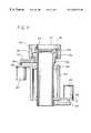
- FIG. 8is a side sectional view taken along lines 8—8 of FIG. 7 .
- FIG. 1illustrates a block diagram of an ophthalmological surgery system for incorporating the invention.
- a personal computer (PC) work station 10is coupled to a single board computer 21 of a laser surgery unit 20 by means of a first bus connection 11 .
- PC work station 10 and the subcomponents of laser surgery unit 20are known components and preferably comprise the elements of the VISX TWENTY/TWENTY EXCIMER LASER SYSTEM available from Visx, Incorporated of Santa Clara, California.
- the laser surgery system 20includes a plurality of sensors generally designated with reference numeral 22 which produce feedback signals from the movable mechanical and optical components in the laser optical system, such as the elements driven by an iris motor 23 , an image rotator 24 , an astigmatism motor 25 and an astigmatism angle motor 26 .
- the feedback signals from sensors 22are provided via appropriate signal conductors to the single board computer 21 , which is preferably an STD bus compatible single board computer using a type 8031 microprocessor.
- the single board computer 21controls the operation of the motor drivers generally designated with reference numeral 27 for operating the elements 23 - 26 .
- single board computer 21controls the operation of the Excimer laser 28 , which is preferably an argon-fluorine laser with a 193 nanometer wavelength output designed to provide feedback stabilized fluence of 160 mJoules per cm 2 at the cornea of the patient's eye 30 via the delivery system optics generally designated with reference numeral 29 and shown in FIG. 6 .
- the Excimer laser 28which is preferably an argon-fluorine laser with a 193 nanometer wavelength output designed to provide feedback stabilized fluence of 160 mJoules per cm 2 at the cornea of the patient's eye 30 via the delivery system optics generally designated with reference numeral 29 and shown in FIG. 6 .
- Other ancillary components of the laser surgery system 20which are not necessary to an understanding of the invention, such as a high resolution microscope, a video monitor for the microscope, a patient eye retention system, and an ablation effluent evacuator/filter, as well as the gas delivery system, have been omitted to avoid prolixity.
- the iris motor 23is used to control the diameter of a variable diameter iris schematically depicted in FIG. 2 .
- the astigmatism motor 25is used to control the separation distance between a pair of cylinder blades 35 , 36 which are mounted on a platform 38 for bi-directional translatory motion in the direction of arrows 40 , 41 .
- Platform 38is rotatably mounted on a second platform (not illustrated) and is rotationally driven by astigmatism angle motor 26 in a conventional way in order to enable alignment of the slit axis (illustrated in a vertical orientation in FIG. 2) with the appropriate coordinate axes of the patient's eye.
- Iris 32is driven by iris motor 23 in a known way to change the diameter of the iris opening from a fully opened position (the position illustrated in FIG. 2) to a fully closed position in which the aperture is closed to a minimum diameter of 0.8 mm. It is understood that the variable diameter iris 32 and the cylinder blades 35 , 36 are positioned with respect to the output of laser 28 in such a manner as to intercept the beam prior to irradiation of the corneal surface of the patient's eye 30 . For the purpose of this application, it may be assumed that iris 32 and cylinder blades 35 , 36 are part of the delivery system optics subunit 29 shown in FIG. 1 .
- FIGS. 1 and 2The system of FIGS. 1 and 2 is used according to the invention to effect hyperopic and other error corrections to the anterior surface of the cornea, to provide a smooth transition zone between the outer edge of the optical zone and the untreated surface of the cornea, and to effect surface smoothing when desired.
- an imaging lens 51is laterally offset from an axis 52 by a variable amount in the manner set forth more fully below.
- Lens 51preferably comprises the existing imaging lens found in the delivery system optics 29 of the FIG. 1 system which are described more fully below.
- Axis 52is the axis corresponding to the center of rotation of lens 51 .
- Displacing lens 51by translating the lens in a radial direction off the axis 52 , which may or may not correspond to the laser beam axis, displaces the image 54 of aperture 53 in a related manner.
- the displaced image 54 of aperture 53can be scanned about axis 52 along a preselected path, which in the hyperopic correction procedure described below is an annular path about the axis 52 .
- various types of large area ablation correctionscan be effected, including hyperopic error corrections, hyperopic astigmatism corrections, and other vision error corrections, along with simultaneous or successive edge contouring to form a smooth transition zone.
- FIG. 5illustrates the aperture positioning relative to the intended ablation center when employing the variable diameter iris 32 and cylinder blades 35 , 36 of FIG. 2 to effect a refractive error correction.
- R 2represents the half width of the slit between blades 35 , 36
- R 1is the radius of the iris 32
- ris the radius of a circle covered by the aperture
- sis the radial offset of the center of the image of the slit aperture relative to the center of rotation 52
- ⁇is the half angle for which the circle of radius r is covered by the aperture.
- the intended optical zoneis the central region bounded by circle 61 and the intended transition zone is the annular region bounded by circles 61 and 62 .
- the manner in which the slit width and diameter are varied by the computerdepends upon the type of vision correction desired.
- the sequencing of the apertureis done in such a manner as to satisfy the hyperopic lens equations described in “Photorefractive Keratectomy: A technique for laser refractive surgery” authored by Munnerlyn et al., J. Cataract Refract. Surg. Vol. 14, pages 46-52 (January, 1988), the disclosure of which is hereby incorporated by reference.
- n iis the number of laser pulses for the i th aperture in a sequence of aperture dimensions and radial positions
- dis the amount of material removed with each laser pulse or a scaling factor which also takes into account corneal healing.
- the sequence of aperture dimensionsis created by control of the width of the slit and the diameter of iris 32 throughout the surgical procedure.
- the sequence of aperture dimensionsmay also be tailored to accommodate variations in the profile of the laser beam.
- the values of s and R 2are varied to produce the correct value of radial offset (s) and slit width (2 ⁇ R 2 ) so that the inner edge of blade 35 is moved in steps from close to the center of the ablation (starting at approximately 0.6 mm from the center) to the edge of the corrected optical zone at approximately 2.5 mm.
- R 1the iris radius
- s and R 2are chosen to anchor the edge of the ablation at the outer edge of the intended transition zone of approximately 5 mm radius.
- the number of pulses for each successive position of the inner edgeis calculated to give the desired depth from the hyperopic lens equation.
- the treatmentis ended as soon as the inner edge of the aperture reaches the boundary of the corrected optical zone.
- the slit widthis set to a maximum value and the imaging lens 51 is positioned laterally of the axis of rotation 52 such that the inner slit edge is positioned at the minimum distance from the center of the optical zone and the intersections of the iris diaphragm 32 and the outer slit edge are positioned over the outer edge of the intended transition zone.
- the image of the apertureis now ready to be scanned over the anterior surface of the cornea. While several different scanning sequences are possible, the following sequence has been actually implemented with effective results.
- the radial position along the optical zoneis broken into a series of discrete, equidistant (typically 0.1 mm apart) nodes.
- the number of pulses required to ablate tissue to cut depth c(r) at a node adjacent to the edge of the inner slitis calculated using
- nis the number of pulses
- ⁇ c(r)the difference between the actual ablation depth from previous pulses and the desired ablation depth at the node
- ⁇ i (r n )is the half angle coverage of the aperture at r n as previously defined.
- the treatmentmust be smoothed rotationally to ensure that it is correct and free from aberrations. Such smoothing is accomplished by rotating the treatment in FIG. 5 about axis 52 . Typically, this rotation is about 127 degrees between pulses.
- the stepper motorsmay take hundreds of seconds to drive the optomechanical parts into position, and the treatment is expedited by sorting the treatment table by angle on the workstation. However, if the treatment were to be interrupted, sorting the table by angle alone would cause the patient to be left with a pie shaped portion of optically correct cornea (pie in the eye). This can be avoided by breaking the treatment table into annular bands of 5 to 10 nodes each. The treatment table is then sorted by angle within each band. Should an interruption in the laser firing occur, the patient is left with a substantially radially symmetric partially complete sculpting. Such an ablation is much easier to realign for completion of the surgery.
- the treatment bandsmay be further subdivided to form hemi-annular regions. This may be advantageous when the aperture can not be rotated by a full 360 degrees, and the eccentric lens motion should be minimized.
- the first half of a treatment bandis ablated, the aperture left in similar angular position, the imaging lens 51 is rotated 180 degrees, and the other half of the band is ablated with subsequent pulses.
- the apertureis left in nearly the same rotational position as it was for the start of the first half of the band, and is consequently well positioned for the start of the second band.
- Such motionwill keep the range of rotation of the aperture under 180 degrees, which is particularly advantageous in systems which are retrofitted and may have been designed only for the treatment of astigmatism.
- the cylinder bladescan be left at constant width during each band by closing the cylinder blades so that at the outermost node of the band, the intersection of the iris diaphragm and outer cylinder blade is coincident with the outer boundary of the ablation.
- the steps of rotating the treatment and sorting it within bandscan all be performed on the workstation prior to treating the patient.
- the laser 28is pulsed, and platform 38 and lens 51 are rotated to a successive angular position displaced from the previous position by an angular amount determined by a treatment table described below.
- any required radial re-positioning of lens 51may be done at this time.
- the laseris again pulsed, platform 38 and lens 51 are again rotated, the laser is again pulsed, etc.
- the slit widthis adjusted by narrowing the width by a predetermined amount, and the lens 51 is adjusted to place the inner slit edge at the appropriate radial position. Thereafter, another series of rotations of platform 38 and lens 51 is carried out, after which the slit width and the radial offset position of lens 51 are adjusted until the inner edge of the slit has reached the boundary 61 of the optical zone and the final series of angular positions has been carried out.
- the above scanning procedurecan be improved by rotating the imaging lens 51 by 180° between laser pulses, followed by the incremental shifting by a predetermined angular amount.
- lens 51can be simply translated diametrically across the axis of rotation. This large angle displacement ensures that diametrically opposite portions of the anterior corneal surface are successively exposed to the profiled laser beam with no overlapping between pulses, which minimizes tissue heating.
- FIG. 6is a schematic view of the delivery system optics in the preferred embodiment.
- the beam from laser 28is reflected by a first mirror 71 and a second mirror 72 , and enters a spatial integrator 73 , where the beam is modified in cross-section.
- the modified beam exiting from spatial integrator 73is reflected by mirrors 74 and 75 and passed through a dove prism 76 to the iris/slit mechanism 78 which contains the variable width slit and variable diameter iris described above.
- the profiled beam exiting from the unit 78is reflected by a mirror 79 and enters the image offset control unit 80 which contains imaging lens 51 .
- the offset profiled image exiting from unit 80is reflected from a mirror 82 onto the patient's eye.
- dove prism 76is rotatably mounted, and is typically rotated during beam generation either continuously or between pulses.
- FIGS. 7 and 8illustrate the image offset control unit 80 .
- imaging lens 51is contained in a fixture 81 , which is mounted for pivotal motion about a first pivot post 83 .
- Post 83is carried by a first mounting member 84 , which in turn is mounted by means of bearings 85 (or other suitable mounting mechanisms) for rotation about the longitudinal axis of member 84 .
- Bearings 85are mounted in the internal recess of a fixture housing 87 .
- a first drive motor 89is mounted on a flange portion 90 of housing 87 and has an output shaft 91 for driving a first drive belt 92 which is coupled to the lower portion of member 84 .
- a second pivot post 93is received in a second pivot aperture 94 formed in fixture 81 .
- Second post 93is secured to an annular upper portion 95 of a second rotatable member 96 .
- a second drive motor 97is mounted on a second flange portion 98 of fixture housing 87 and has an output shaft 99 for driving a second drive belt 101 .
- Second drive belt 101is arranged in driving engagement with the lower collar portion 103 of member 96 .
- the inventionoffers the advantage of relatively wide area coverage without requiring a laser beam of size approximately equal to the treatment area.
- the transition zonecan be fully formed using a controlled laser beam having a beam area substantially smaller than those required in prior art systems. This is highly advantageous since it requires substantially less energy than a larger beam generating laser, and avoids premature failure of optical components which are subject to deterioration due to high energy levels.
- the laser beam sizeshould be large enough to cover the largest variable aperture required to effect the desired ablation.
- the maximum variable aperture contemplated with the slit/iris aperturehas a largest dimension of approximately one half the largest treatment area. For most human eyes, this largest treatment area is approximately 10 mm.
- a laser having a beam diameter of about 5 mmwill provide regular ablations according to the invention.
- the laserhas a beam with a 6 mm maximum width.
- the inventioncan be implemented in existing laser surgery systems by merely modifying the delivery system optics to enable the imaging lens 51 to be offset from the beam axis by selected amounts and to rotate with variable width slit/variable diameter iris arrangement. The design and construction of such modifications will be readily apparent to those of ordinary skill in the art of optomechanical design. Further, other types of corrections than hyperopic corrections can be effected by properly programming computer 21 to adjust the slit width and aperture radius.
- variable slit width/variable diameter iris arrangementis particularly adaptable for use in the treatment of hyperopia, hyperopic astigmatism and irregular refractive aberrations.
- the ablation geometryis solved as a function of radial displacement and angular position of the aperture image about the rotational center.
- the diameter of the irisis varied over a predetermined range along with the slit width variation.
- a devicesuch as a spatially resolved refractometer or a topography machine or both may be used to map the irregular surface contour of the cornea to determine the exact surface corrections required. Thereafter, the slit width and the iris diameter can be programmed such that corneal sculpting will achieve the desired spherical surface geometry.
- the inventioncan be used for other visual error corrections, both regular and irregular, for phototherapeutic keratectomy (typically used to ablate scar tissue), and for smoothing ablations.
- a variable diameter circular apertureis scanned in an elliptical or other pattern of various sizes to create a smooth toric ablation.
- Such an ablationmay contain a transition zone at-the edge of the optical zone.
- a laser with a maximum treatment diameter of six millimeterswill produce a toric ablation with a maximum minor axis value of 4.25 mm.
- An analogous ablation made with the eccentric rotating technique of the invention and a variable diameter iris using the same laser beamcan produce a toric ablation with major and minor axes of 8.5 mm and 6.0 mm, respectively. As will be apparent to those skilled in the art, this provides much better coverage over the patient's pupil. In addition, the larger ablation is more likely to provide greater refractive stability than the smaller ablation.
- the iris diaphragmis set to a maximum value, and the eccentric lens is used to scan an ablated cylinder in periodic motion along the cylinder axis to produce longer cylindrical ablations. This negates the need to close the iris diaphragm while the laser is pulsed. Adjacent material may also be ablated on the ends of the cylinder so as to further extend the transition zone from the optical zone.
- a scar which occurs centrally over the corneacan be ablated with the excimer laser by ablating a large area with a transition zone at the edge.
- a circular aperturehas typically been imaged to approximately 6 mm diameter, and then opened or closed slightly while the laser fires a predetermined number of pulses to effect a transition zone and ablate the central scar.
- the inventionmay also be used to treat irregular astigmatism to provide appropriate contour sculpting to effect correction of visual errors which cannot be fully corrected with eyeglasses (which only correct for sphere and cylinder). Since the geometry ablated according to the invention is not constrained to simple spherical and cylindrical geometries, irregular astigmatism can be treated in an especially effective manner. For example, a patient may have a corneal geometry which departs from spherical by conical rather than cylindrical geometry. In such a case, the cylinder blades are aligned similarly to the treatment of astigmatism.
- the combined motion of the eccentric lens and the cylinder bladeswill be such that one end of the image of the cylinder blade pair will be constant on the cornea, while the other end will be variably displaced during the ablation along an arc transverse to the cylinder axis.
- This techniquecan be extended to the use of elliptical ablations, resulting in ablations which would appear as distorted ovals rather than ellipses.
- the inventionmay be used to smooth ablations by displacing the rotational center of the profiled beam in a random or pseudo-random pattern so that beam defects are averaged over a much larger area.
- a myopic ablationcan be smoothed by scanning the iris diaphragm in a circular pattern as the iris diaphragm closes. This can produce a transition zone with gentle taper from the untreated area to the optical zone.
- Both the radial offset of the eccentric lens and the size of the iris diaphragmare varied during the treatment to produce a series of overlapping circular ablations of varying diameter and varying offset about the intended ablation center.
- a treatment tableis normally constructed containing the value of all of the discrete radial and angular positions of the optomechanical elements used to scan the image over the relevant portion of the anterior corneal surface, as well as the number of laser pulses per position.
- a typical treatment tablecontains on the order of about 500 different entries.
- a sample of a one Diopter hyperopic treatment tableis shown in appendix I.
- electromechanical elementssuch as iris motor 23 , astigmatism motor 25 , astigmatism angle motor 26 and the elements contained in the image offset control unit 80 all require finite minimum time periods to reposition the image.
- the treatment tableis sorted by the computer work station 10 to optimize the motion of the mechanical elements.
- the sorting processis done on the basis of both angular position and radial position, and a best fit approach is used to determine the angular and radial stepping sequences.
- the treatment tableis also sorted into radial bands and the required angular positions within each band are established. The optomechanical elements are then driven in accordance with the sorted treatment table to carry out the procedure one band at a time.
- the first band selected for ablationmay be the outermost annular band, followed by the next inner band and continuing until the central band is completed.
- the overall treatmentBy separating the overall treatment into bands, motion of the mechanical elements within each particular band can be optimized. Also, in the event of an interruption in the treatment before completion, the patient will be left with a partially completed ablation pattern which will be easier to align when the procedure is resumed or which is optically beneficial if the procedure cannot be resumed.
- the treatment table for a given proceduremay incorporate special features designed to improve the efficiency of the procedure. For example, for some procedures (e.g., hyperopic correction) it can be beneficial to leave a small zone centered on the optical zone untreated. This can be done by constraining motion of the inner cylinder blade to guarantee occlusion in the small zone of interest. Further, compensation for variable or differential healing rates and for differential ablation depth due to tissue hydration may be factored into the treatment table. Also, standard tables can be constructed for a specific procedure —e.g., myopic correction —to different Dioptric correction values, and these standard tables can be sorted and combined to perform multiple repetitions of one or more standard tables to effect a given Dioptric correction.
- myopic correctionto different Dioptric correction values
- standard tablesmay be created for a myopic correction for values of 1 ⁇ 4, 1 ⁇ 2and 1 Diopter. Using these tables, a 3.75 Diopter correction would proceed by performing the standard 1 Diopter correction three times, followed by the 1 ⁇ 2Diopter correction and the 1 ⁇ 4Diopter correction.
- the inventionhas been described above with specific reference to ablation of the anterior corneal surface, other portions of the cornea may also be treated using the invention.
- the epitheliummay be mechanically removed by scraping, as is typically done in photorefractive keratectomy, and the exposed surface may be ablated.
- the inventioncan also be used for laser keratomileusis of corneal lamella removed from the cornea. This procedure is described in U.S. Pat. No. 4,903,695 issued Feb. 27, 1990 for “Method and Apparatus For Performing A Keratomileusis Or The Like Operation”.
- a flap of corneal tissueis physically removed from the cornea, the size of the removed portion typically lying in the range from about 8 to 10 mm wide and a variable thickness up to 400 microns.
- This flap of tissueis typically removed using a microkeratome.
- the flapis placed in a suitable fixture — typically an element having a concave surface — with the anterior surface face down.
- the required ablationis performed on the reverse exposed surface of the flap, after which the ablated flap is repositioned on the cornea and re-attached by suturing.
- the exposed stromal tissue of the eyecan be ablated according to the invention, after which the flap is re-attached over the freshly ablated stromal tissue.
Landscapes
- Health & Medical Sciences (AREA)
- Ophthalmology & Optometry (AREA)
- Heart & Thoracic Surgery (AREA)
- Vascular Medicine (AREA)
- Optics & Photonics (AREA)
- Surgery (AREA)
- Engineering & Computer Science (AREA)
- Biomedical Technology (AREA)
- Physics & Mathematics (AREA)
- Nuclear Medicine, Radiotherapy & Molecular Imaging (AREA)
- Life Sciences & Earth Sciences (AREA)
- Animal Behavior & Ethology (AREA)
- General Health & Medical Sciences (AREA)
- Public Health (AREA)
- Veterinary Medicine (AREA)
- Laser Surgery Devices (AREA)
Abstract
Description
| LASER TREATMENT TABLE |
| IRIS RADIUS 3.0 MM |
| CYL | CYL | LENS | LENS | LASER |
| WIDTH | AXIS | OFFSET | ROTATION | PULSES |
| 2.60 | 12.91 | 2.30 | 12.91 | 1 |
| 2.60 | 21.87 | 1.85 | 21.87 | 1 |
| 2.60 | 43.75 | 2.07 | 43.75 | 1 |
| 2.60 | 65.62 | 2.25 | 65.62 | 1 |
| 2.60 | 74.58 | 1.78 | 74.58 | 1 |
| 2.60 | 96.45 | 2.00 | 96.45 | 1 |
| 2.60 | 118.33 | 2.20 | 118.33 | 1 |
| 2.60 | 127.29 | 1.63 | 127.29 | 1 |
| 2.60 | 149.16 | 1.95 | 149.16 | 1 |
| 2.60 | 171.04 | 2.15 | 171.04 | 1 |
| 2.60 | 171.04 | 2.15 | 351.04 | 1 |
| 2.60 | 149.16 | 1.95 | 329.16 | 1 |
| 2.60 | 127.29 | 1.63 | 307.29 | 1 |
| 2.60 | 118.33 | 2.20 | 298.33 | 1 |
| 2.60 | 96.45 | 2.00 | 276.46 | 1 |
| 2.60 | 74.58 | 1.78 | 254.58 | 1 |
| 2.60 | 65.62 | 2.25 | 245.62 | 1 |
| 2.60 | 43.75 | 2.07 | 223.75 | 1 |
| 2.60 | 21.87 | 1.85 | 201.87 | 1 |
| 2.60 | 12.91 | 2.30 | 192.91 | 1 |
| 2.00 | 3.95 | 2.30 | 3.95 | 1 |
| 2.00 | 25.82 | 2.40 | 25.82 | 1 |
| 2.00 | 34.78 | 2.12 | 34.78 | 1 |
| 2.00 | 56.66 | 2.25 | 56.66 | 1 |
| 2.00 | 78.53 | 2.35 | 78.53 | 1 |
| 2.00 | 87.49 | 2.10 | 87.49 | 1 |
| 2.00 | 100.40 | 2.45 | 100.40 | 1 |
| 2.00 | 109.36 | 2.20 | 109.36 | 1 |
| 2.00 | 131.24 | 2.33 | 131.24 | 1 |
| 2.00 | 140.20 | 2.05 | 140.20 | 1 |
| 2.00 | 153.11 | 2.43 | 153.11 | 1 |
| 2.00 | 162.07 | 2.18 | 162.07 | 1 |
| 2.00 | 162.07 | 2.18 | 342.07 | 1 |
| 2.00 | 153.11 | 2.43 | 333.11 | 1 |
| 2.00 | 140.20 | 2.05 | 320.20 | 1 |
| 2.00 | 131.24 | 2.33 | 311.24 | 1 |
| 2.00 | 109.36 | 2.20 | 289.37 | 1 |
| 2.00 | 100.40 | 2.45 | 280.40 | 1 |
| 2.00 | 87.49 | 2.10 | 267.49 | 1 |
| 2.00 | 78.53 | 2.35 | 258.53 | 1 |
| 2.00 | 56.66 | 2.25 | 236.66 | 1 |
| 2.00 | 34.78 | 2.12 | 214.78 | 1 |
| 2.00 | 25.82 | 2.40 | 205.82 | 1 |
| 2.00 | 3.95 | 2.30 | 183.95 | 1 |
| 1.50 | 7.89 | 2.55 | 7.89 | 1 |
| 1.50 | 16.86 | 2.35 | 16.86 | 1 |
| 1.50 | 29.77 | 2.63 | 29.77 | 1 |
| 1.50 | 38.73 | 2.45 | 38.73 | 1 |
| 1.50 | 47.69 | 2.25 | 47.69 | 1 |
| 1.50 | 51.64 | 2.70 | 51.64 | 1 |
| 1.50 | 60.60 | 2.53 | 60.60 | 1 |
| 1.50 | 69.57 | 2.33 | 69.57 | 1 |
| 1.50 | 82.48 | 2.60 | 82.48 | 1 |
| 1.50 | 91.44 | 2.43 | 91.44 | 1 |
| 1.50 | 104.35 | 2.68 | 104.35 | 1 |
| 1.50 | 113.31 | 2.50 | 113.31 | 1 |
| 1.50 | 122.27 | 2.30 | 122.27 | 1 |
| 1.50 | 135.18 | 2.58 | 135.18 | 1 |
| 1.50 | 144.15 | 2.40 | 144.15 | 1 |
| 1.50 | 157.06 | 2.65 | 157.06 | 1 |
| 1.50 | 166.02 | 2.48 | 166.02 | 1 |
| 1.50 | 174.98 | 2.28 | 174.98 | 1 |
| 1.50 | 178.93 | 2.73 | 178.93 | 1 |
| 1.50 | 178.93 | 2.73 | 358.93 | 1 |
| 1.50 | 174.98 | 2.28 | 354.98 | 1 |
| 1.50 | 166.02 | 2.48 | 346.02 | 1 |
| 1.50 | 157.06 | 2.65 | 337.06 | 1 |
| 1.50 | 144.15 | 2.40 | 324.15 | 1 |
| 1.50 | 135.18 | 2.58 | 315.18 | 1 |
| 1.50 | 122.27 | 2.30 | 302.27 | 1 |
| 1.50 | 113.31 | 2.50 | 293.31 | 1 |
| 1.50 | 104.35 | 2.68 | 284.35 | 1 |
| 1.50 | 91.44 | 2.43 | 271.44 | 1 |
| 1.50 | 82.48 | 2.60 | 262.48 | 1 |
| 1.50 | 69.57 | 2.33 | 249.57 | 1 |
| 1.50 | 60.60 | 2.53 | 240.60 | 1 |
| 1.50 | 51.64 | 2.70 | 231.64 | 1 |
| 1.50 | 47.69 | 2.25 | 227.69 | 1 |
| 1.50 | 38.73 | 2.45 | 218.73 | 1 |
| 1.50 | 29.77 | 2.63 | 209.77 | 1 |
| 1.50 | 16.86 | 2.35 | 196.86 | 1 |
| 1.50 | 7.89 | 2.55 | 187.89 | 1 |
| .90 | 2.88 | 2.78 | 2.88 | 1 |
| .90 | 11.84 | 2.65 | 11.84 | 1 |
| .90 | 15.79 | 2.95 | 15.79 | 1 |
| .90 | 20.80 | 2.50 | 20.80 | 1 |
| .90 | 24.75 | 2.82 | 24.75 | 1 |
| .90 | 33.71 | 2.70 | 33.71 | 1 |
| .90 | 42.68 | 2.55 | 42.68 | 1 |
| .90 | 46.62 | 2.90 | 46.62 | 1 |
| .90 | 55.59 | 2.75 | 55.59 | 1 |
| .90 | 64.55 | 2.63 | 64.55 | 1 |
| .90 | 68.50 | 2.95 | 68.50 | 1 |
| .90 | 73.51 | 2.48 | 73.51 | 1 |
| .90 | 77.46 | 2.82 | 77.46 | 1 |
| .90 | 86.42 | 2.68 | 86.42 | 1 |
| .90 | 95.39 | 2.55 | 95.39 | 1 |
| .90 | 99.33 | 2.87 | 99.33 | 1 |
| .90 | 108.30 | 2.75 | 108.30 | 1 |
| .90 | 117.26 | 2.60 | 117.26 | 1 |
| .90 | 121.21 | 2.92 | 121.21 | 1 |
| .90 | 126.22 | 2.45 | 126.22 | 1 |
| .90 | 130.17 | 2.80 | 130.17 | 1 |
| .90 | 139.13 | 2.68 | 139.13 | 1 |
| .90 | 148.09 | 2.53 | 148.09 | 1 |
| .90 | 152.04 | 2.85 | 152.04 | 1 |
| .90 | 161.00 | 2.73 | 161.00 | 1 |
| .90 | 169.97 | 2.58 | 169.97 | 1 |
| .90 | 173.91 | 2.90 | 173.91 | 1 |
| .90 | 173.91 | 2.90 | 353.91 | 1 |
| .90 | 169.97 | 2.58 | 349.97 | 1 |
| .90 | 161.00 | 2.73 | 341.00 | 1 |
| .90 | 152.04 | 2.85 | 332.04 | 1 |
| .90 | 148.09 | 2.53 | 328.09 | 1 |
| .90 | 139.13 | 2.68 | 319.13 | 1 |
| .90 | 130.17 | 2.80 | 310.17 | 1 |
| .90 | 126.22 | 2.45 | 306.22 | 1 |
| .90 | 121.21 | 2.92 | 301.21 | 1 |
| .90 | 117.26 | 2.60 | 297.26 | 1 |
| .90 | 108.30 | 2.75 | 288.30 | 1 |
| .90 | 99.33 | 2.87 | 279.33 | 1 |
| .90 | 95.39 | 2.55 | 275.39 | 1 |
| .90 | 86.42 | 2.68 | 266.42 | 1 |
| .90 | 77.46 | 2.82 | 257.46 | 1 |
| .90 | 73.51 | 2.48 | 253.51 | 1 |
| .90 | 68.50 | 2.95 | 248.50 | 1 |
| .90 | 64.55 | 2.63 | 244.55 | 1 |
| .90 | 55.59 | 2.75 | 235.59 | 1 |
| .90 | 46.62 | 2.90 | 226.62 | 1 |
| .90 | 42.68 | 2.55 | 222.68 | 1 |
| .90 | 33.71 | 2.70 | 213.71 | 1 |
| .90 | 24.75 | 2.82 | 204.75 | 1 |
| .90 | 20.80 | 2.50 | 200.80 | 1 |
| .90 | 15.79 | 2.95 | 195.79 | 1 |
| .90 | 11.84 | 2.65 | 191.84 | 1 |
| .90 | 2.88 | 2.78 | 182.88 | 1 |
Claims (39)
Priority Applications (5)
| Application Number | Priority Date | Filing Date | Title |
|---|---|---|---|
| US08/968,380US6203539B1 (en) | 1993-05-07 | 1997-11-12 | Method and system for laser treatment of refractive errors using offset imaging |
| US09/379,372US6319247B1 (en) | 1993-05-07 | 1999-08-23 | Systems and methods for corneal surface ablation to correct hyperopia |
| US09/730,072US6755818B2 (en) | 1993-05-07 | 2000-12-05 | Method and system for laser treatment of refractive errors using offset imaging |
| US09/923,863US20020016586A1 (en) | 1993-05-07 | 2001-08-06 | Method and system for laser treatment of refractive errors using offset imaging |
| US09/950,563US7582081B2 (en) | 1993-05-07 | 2001-09-10 | Systems and methods for corneal surface ablation to correct hyperopia |
Applications Claiming Priority (2)
| Application Number | Priority Date | Filing Date | Title |
|---|---|---|---|
| US5859993A | 1993-05-07 | 1993-05-07 | |
| US08/968,380US6203539B1 (en) | 1993-05-07 | 1997-11-12 | Method and system for laser treatment of refractive errors using offset imaging |
Related Parent Applications (2)
| Application Number | Title | Priority Date | Filing Date |
|---|---|---|---|
| US5859993AContinuation | 1993-05-07 | 1993-05-07 | |
| US90602097AContinuation-In-Part | 1993-05-07 | 1997-08-05 |
Related Child Applications (3)
| Application Number | Title | Priority Date | Filing Date |
|---|---|---|---|
| US90602097AContinuation-In-Part | 1993-05-07 | 1997-08-05 | |
| US09/379,372Continuation-In-PartUS6319247B1 (en) | 1993-05-07 | 1999-08-23 | Systems and methods for corneal surface ablation to correct hyperopia |
| US09/730,072ContinuationUS6755818B2 (en) | 1993-05-07 | 2000-12-05 | Method and system for laser treatment of refractive errors using offset imaging |
Publications (1)
| Publication Number | Publication Date |
|---|---|
| US6203539B1true US6203539B1 (en) | 2001-03-20 |
Family
ID=22017814
Family Applications (3)
| Application Number | Title | Priority Date | Filing Date |
|---|---|---|---|
| US08/968,380Expired - LifetimeUS6203539B1 (en) | 1993-05-07 | 1997-11-12 | Method and system for laser treatment of refractive errors using offset imaging |
| US09/730,072Expired - Fee RelatedUS6755818B2 (en) | 1993-05-07 | 2000-12-05 | Method and system for laser treatment of refractive errors using offset imaging |
| US09/923,863AbandonedUS20020016586A1 (en) | 1993-05-07 | 2001-08-06 | Method and system for laser treatment of refractive errors using offset imaging |
Family Applications After (2)
| Application Number | Title | Priority Date | Filing Date |
|---|---|---|---|
| US09/730,072Expired - Fee RelatedUS6755818B2 (en) | 1993-05-07 | 2000-12-05 | Method and system for laser treatment of refractive errors using offset imaging |
| US09/923,863AbandonedUS20020016586A1 (en) | 1993-05-07 | 2001-08-06 | Method and system for laser treatment of refractive errors using offset imaging |
Country Status (6)
| Country | Link |
|---|---|
| US (3) | US6203539B1 (en) |
| EP (1) | EP0628298B1 (en) |
| JP (1) | JP3618781B2 (en) |
| BR (1) | BR9401668A (en) |
| CO (1) | CO4230054A1 (en) |
| DE (1) | DE69409285T2 (en) |
Cited By (104)
| Publication number | Priority date | Publication date | Assignee | Title |
|---|---|---|---|---|
| WO2002046801A2 (en) | 2000-12-08 | 2002-06-13 | Visx, Incorporated | Direct wavefront-based corneal ablation treatment program |
| US6406473B1 (en)* | 1999-10-01 | 2002-06-18 | Visx, Incorporated | Patient fixation system and method for laser eye surgery |
| US6409718B1 (en)* | 1998-02-03 | 2002-06-25 | Lasersight Technologies, Inc. | Device and method for correcting astigmatism by laser ablation |
| US20030176855A1 (en)* | 2002-03-14 | 2003-09-18 | Visx, Inc. | Application of blend zones, depth reduction, and transition zones to ablation shapes |
| US20030220631A1 (en)* | 1999-04-07 | 2003-11-27 | Visx, Incorporated | Offset ablation profiles for treatment of irregular astigmatism |
| WO2003101325A1 (en) | 2002-05-30 | 2003-12-11 | Visx, Incorporated | Thermal modeling for reduction of refractive laser surgery times |
| WO2003101326A1 (en) | 2002-05-30 | 2003-12-11 | Visx, Incorporated | Variable repetition rate firing scheme for refractive laser systems |
| WO2003105722A2 (en) | 2002-06-13 | 2003-12-24 | Visx, Incorporated | Corneal topography-based target warping |
| US20030236516A1 (en)* | 2002-06-24 | 2003-12-25 | Keiki Okamoto | Corneal-ablation-amount determining apparatus and a corneal surgery apparatus |
| US6673062B2 (en)* | 2000-03-14 | 2004-01-06 | Visx, Inc. | Generating scanning spot locations for laser eye surgery |
| US6679876B2 (en) | 2000-10-20 | 2004-01-20 | Nidek Co., Ltd. | Corneal surgery apparatus |
| US20040021874A1 (en)* | 2002-06-27 | 2004-02-05 | Visx, Incorporated, A Delaware Corporation | Integrated scanning and ocular tomography system and method |
| US20040044333A1 (en)* | 2002-08-29 | 2004-03-04 | Motohiro Sugiura | Corneal surgery apparatus |
| US20040059320A1 (en)* | 2002-09-06 | 2004-03-25 | Alain Telandro | Corneal-ablation-data calculation apparatus and a corneal surgery apparatus |
| US6712808B2 (en) | 2000-10-02 | 2004-03-30 | Nidek Co., Ltd. | Laser surgery apparatus |
| US6755818B2 (en)* | 1993-05-07 | 2004-06-29 | Visx, Incorporated | Method and system for laser treatment of refractive errors using offset imaging |
| US20040143246A1 (en)* | 2003-01-15 | 2004-07-22 | Naoyuki Maeda | Corneal surgery apparatus |
| US20040147910A1 (en)* | 2002-08-01 | 2004-07-29 | Masanao Fujieda | Method and apparatus for obtaining irradiation intensity of a laser beam, and apparatus for irradiating the laser beam |
| US20040156015A1 (en)* | 2003-02-10 | 2004-08-12 | Visx, Inc. | Eye refractor with active mirror wavefront sensor |
| US20040172106A1 (en)* | 2002-10-24 | 2004-09-02 | Satoshi Imaizumi | Apparatus for ablation with a laser beam |
| US6793654B2 (en) | 1999-12-23 | 2004-09-21 | Visx, Inc. | Optical feedback system for vision correction |
| US20040199224A1 (en)* | 2000-12-05 | 2004-10-07 | Visx, Incorporated | Method and system for laser treatment of refractive errors using offset imaging |
| US20040263785A1 (en)* | 2003-06-16 | 2004-12-30 | Visx, Inc. | Methods and devices for registering optical measurement datasets of an optical system |
| US6843787B2 (en)* | 1994-06-29 | 2005-01-18 | Luis Antonio Ruiz | Apparatus and method for performing presbyopia corrective surgery |
| US20050024584A1 (en)* | 2003-07-31 | 2005-02-03 | Visx, Incorporated | Systems and methods for eye aberration and image sensor orientation |
| US20050096640A1 (en)* | 2003-04-18 | 2005-05-05 | Visx, Incorporated | Systems and methods for correcting high order aberrations in laser refractive surgery |
| US20050185138A1 (en)* | 2004-02-19 | 2005-08-25 | Visx, Incorporated | Methods and systems for differentiating left and right eye images |
| WO2005089185A2 (en) | 2004-03-15 | 2005-09-29 | Visx, Incorporated | Stabilizing delivered laser energy |
| WO2005092172A1 (en) | 2004-03-03 | 2005-10-06 | Visx, Incorporated | Transformation methods of wavefront maps from one vertex distance to another |
| US20050247894A1 (en)* | 2004-05-05 | 2005-11-10 | Watkins Charles M | Systems and methods for forming apertures in microfeature workpieces |
| US20060095099A1 (en)* | 2004-02-04 | 2006-05-04 | Shanks Steven C | Stand-alone scanning laser device |
| US7052490B2 (en) | 2000-09-29 | 2006-05-30 | Nidek Co., Ltd. | Corneal surgery apparatus and correction data determining methods |
| WO2006076653A2 (en) | 2005-01-13 | 2006-07-20 | Visx, Incorporated | Database system for centralized clinical and research applications with data from wavefront aberrometers |
| US20060224218A1 (en)* | 2004-02-04 | 2006-10-05 | Kevin Tucek | Scanning treatment laser with sweep beam spot and universal carriage |
| WO2006127173A2 (en) | 2005-05-20 | 2006-11-30 | Visx, Incorporated | Scleral lenses for custom optic evaluation and visual performance improvement |
| US20070045826A1 (en)* | 2005-09-01 | 2007-03-01 | Micron Technology, Inc. | Microfeature workpiece substrates having through-substrate vias, and associated methods of formation |
| US20070201001A1 (en)* | 2006-02-24 | 2007-08-30 | Visx, Incorporated | Scaling zernike coefficients to smaller pupil sizes for refractive treatments |
| US20070213697A1 (en)* | 2006-03-10 | 2007-09-13 | Visx, Incorporated | Output energy control for lasers |
| WO2008061034A1 (en) | 2006-11-10 | 2008-05-22 | Amo Manufacturing Usa, Llc | Operator-controlled scanning laser procedure designed for large-area epithelium removal |
| US7431457B2 (en) | 2002-05-30 | 2008-10-07 | Amo Manufacturing Usa, Llc | Methods and systems for tracking a torsional orientation and position of an eye |
| US20080287928A1 (en)* | 2006-11-10 | 2008-11-20 | Amo Development, Llc | Operator-controlled scanning laser procedure designed for large-area epithelium removal |
| US20080287929A1 (en)* | 2007-05-17 | 2008-11-20 | Amo Development, Llc | Customized laser epithelial ablation systems and methods |
| WO2008148038A1 (en) | 2007-05-24 | 2008-12-04 | Amo Development, Llc | Accommodation compensation systems and methods |
| US20090004179A1 (en)* | 2005-11-07 | 2009-01-01 | The Rockefeller University | Polypeptides with enhanced anti-inflammatory and decreased cytotoxic properties and relating methods |
| US20090008144A1 (en)* | 2004-08-27 | 2009-01-08 | Micron Technology, Inc. | Slanted vias for electrical circuits on circuit boards and other substrates |
| US20090033867A1 (en)* | 2007-08-01 | 2009-02-05 | Visx, Incorporated | Wavefront refractions and high order aberration correction when wavefront maps involve geometrical transformations |
| US20090118716A1 (en)* | 2007-11-07 | 2009-05-07 | Intralase, Inc. | System and method for scanning a pulsed laser beam |
| US7531453B2 (en) | 2004-06-29 | 2009-05-12 | Micron Technology, Inc. | Microelectronic devices and methods for forming interconnects in microelectronic devices |
| US20090125005A1 (en)* | 2002-02-11 | 2009-05-14 | Amo Manufacturing Usa, Llc | Closed Loop System and Method for Ablating Lenses with Aberrations |
| US20090132012A1 (en)* | 2007-11-16 | 2009-05-21 | Therapy Products, Inc. | Method for pretreating patient before surgery |
| US20090216217A1 (en)* | 1998-03-04 | 2009-08-27 | Amo Manufacturing Usa, Llc. | Method and systems for laser treatment of presbyopia using offset imaging |
| US20090292275A1 (en)* | 2008-04-22 | 2009-11-26 | Amo Development Llc | High-order optical correction during corneal laser surgery |
| US7629249B2 (en) | 2006-08-28 | 2009-12-08 | Micron Technology, Inc. | Microfeature workpieces having conductive interconnect structures formed by chemically reactive processes, and associated systems and methods |
| US7683458B2 (en) | 2004-09-02 | 2010-03-23 | Micron Technology, Inc. | Through-wafer interconnects for photoimager and memory wafers |
| CN1861215B (en)* | 2005-05-09 | 2010-04-14 | 上海希格玛高技术有限公司 | Irradiation distance positioning method of phototherapy instrument and phototherapy instrument adopting the method |
| US20100144659A1 (en)* | 2007-03-30 | 2010-06-10 | Nitto Denko Corporation | Targeting agent for cancer cell or cancer-associated fibroblast |
| US7749899B2 (en) | 2006-06-01 | 2010-07-06 | Micron Technology, Inc. | Microelectronic workpieces and methods and systems for forming interconnects in microelectronic workpieces |
| US7759800B2 (en) | 2003-11-13 | 2010-07-20 | Micron Technology, Inc. | Microelectronics devices, having vias, and packaged microelectronic devices having vias |
| US20100196497A1 (en)* | 2009-02-02 | 2010-08-05 | Therapy Products, Inc. | Method of Treating Tissue Using Platelet-Rich Plasma in Combination with Low-Level Laser Therapy |
| US7795134B2 (en) | 2005-06-28 | 2010-09-14 | Micron Technology, Inc. | Conductive interconnect structures and formation methods using supercritical fluids |
| EP2229873A1 (en) | 2003-06-20 | 2010-09-22 | AMO Manufacturing USA, LLC | Method and system for determining an optical surface model |
| US20100253909A1 (en)* | 2006-02-24 | 2010-10-07 | Amo Development, Llc | Induced high order aberrations corresponding to geometrical transformations |
| US7830018B2 (en) | 2007-08-31 | 2010-11-09 | Micron Technology, Inc. | Partitioned through-layer via and associated systems and methods |
| US7863187B2 (en) | 2005-09-01 | 2011-01-04 | Micron Technology, Inc. | Microfeature workpieces and methods for forming interconnects in microfeature workpieces |
| US20110028955A1 (en)* | 2009-07-29 | 2011-02-03 | Lensx Lasers, Inc. | Optical System For Ophthalmic Surgical Laser |
| US20110028951A1 (en)* | 2009-07-29 | 2011-02-03 | Lensx Lasers, Inc. | Optical System with Movable Lens for Ophthalmic Surgical Laser |
| US20110028958A1 (en)* | 2009-07-29 | 2011-02-03 | Lensx Lasers, Inc. | Optical System for Ophthalmic Surgical Laser |
| US7884015B2 (en) | 2007-12-06 | 2011-02-08 | Micron Technology, Inc. | Methods for forming interconnects in microelectronic workpieces and microelectronic workpieces formed using such methods |
| US7902643B2 (en) | 2006-08-31 | 2011-03-08 | Micron Technology, Inc. | Microfeature workpieces having interconnects and conductive backplanes, and associated systems and methods |
| US7915736B2 (en) | 2005-09-01 | 2011-03-29 | Micron Technology, Inc. | Microfeature workpieces and methods for forming interconnects in microfeature workpieces |
| US20110118713A1 (en)* | 2009-11-16 | 2011-05-19 | Lensx Lasers, Inc. | Variable Stage Optical System For Ophthalmic Surgical Laser |
| WO2011066555A1 (en) | 2009-11-30 | 2011-06-03 | Amo Development, Llc | Systems and methods for fine-tuning refractive surgery |
| US20110149241A1 (en)* | 2006-02-24 | 2011-06-23 | Amo Development, Llc | Zone extension systems and methods |
| WO2011123556A1 (en) | 2010-03-30 | 2011-10-06 | Amo Development, Llc | System and method for evaluating treatment tables for refractive surgery |
| US8084866B2 (en) | 2003-12-10 | 2011-12-27 | Micron Technology, Inc. | Microelectronic devices and methods for filling vias in microelectronic devices |
| WO2012178054A1 (en) | 2011-06-23 | 2012-12-27 | Amo Development, Llc | Ophthalmic range finding |
| WO2013013175A1 (en) | 2011-07-20 | 2013-01-24 | Amo Development, Llc. | Manifest refraction treatment systems and methods |
| WO2013012803A1 (en) | 2011-07-16 | 2013-01-24 | Amo Manufacturing Usa, Llc. | Compound modulation transfer function for laser surgery and other optical applications |
| WO2013013182A1 (en) | 2011-07-21 | 2013-01-24 | Amo Development, Llc. | Tilt compensation, measurement, and associated adjustment of refractive prescriptions during surgical and other treatments of the eye |
| WO2013082466A1 (en) | 2011-11-30 | 2013-06-06 | Amo Development, Llc. | System and method for ophthalmic surface measurements based on sequential estimates |
| WO2013126653A1 (en) | 2012-02-22 | 2013-08-29 | Amo Development, Llc | Preformed lens systems and methods |
| WO2014015234A2 (en) | 2012-07-20 | 2014-01-23 | Amo Manufacturing Usa, Llc. | Systems and methods for correcting high order aberrations in laser refractive surgery |
| WO2014055690A1 (en) | 2012-10-02 | 2014-04-10 | Amo Development, Llc. | Systems and methods for treatment target deconvolution |
| WO2014066671A1 (en) | 2012-10-24 | 2014-05-01 | Amo Development, Llc. | Scanning lens system and methods of reducing reaction forces therein |
| US8764737B2 (en) | 2007-09-06 | 2014-07-01 | Alcon Lensx, Inc. | Precise targeting of surgical photodisruption |
| WO2014149839A1 (en) | 2013-03-15 | 2014-09-25 | Amo Wavefront Sciences, Llc | Angular multiplexed optical coherence tomography systems and methods |
| US8852177B2 (en) | 2012-03-09 | 2014-10-07 | Alcon Lensx, Inc. | Spatio-temporal beam modulator for surgical laser systems |
| WO2015070092A1 (en) | 2013-11-07 | 2015-05-14 | Amo Development Llc | Treatment validation systems and methods |
| WO2015103273A1 (en) | 2013-12-31 | 2015-07-09 | Amo Development, Llc. | Wavefront measurement pre-smoothing systems and methods |
| US9101446B2 (en) | 2008-01-02 | 2015-08-11 | Intralase Corp. | System and method for scanning a pulsed laser beam |
| US9108270B2 (en) | 2008-01-02 | 2015-08-18 | Amo Development, Llc | System and method for scanning a pulsed laser beam |
| WO2015191386A1 (en) | 2014-06-11 | 2015-12-17 | Amo Development, Llc | Basis data evaluation systems and methods |
| WO2016025315A1 (en) | 2014-08-11 | 2016-02-18 | Amo Development, Llc | Optical surface systems and methods for treatment of presbyopia and other vision conditions |
| WO2016111851A1 (en) | 2015-01-09 | 2016-07-14 | Amo Development, Llc | Vergence weighting systems and methods for treatment of presbyopia and other vision conditions |
| US9521949B2 (en) | 2011-06-23 | 2016-12-20 | Amo Development, Llc | Ophthalmic range finding |
| US9642518B2 (en) | 2010-03-30 | 2017-05-09 | Amo Development, Llc | Random eye generation systems and methods |
| WO2018031812A1 (en) | 2016-08-10 | 2018-02-15 | Amo Development, Llc | Epithelial ablation systems and methods |
| WO2018102624A1 (en) | 2016-12-01 | 2018-06-07 | Amo Development, Llc | Spherical aberration reduction systems and methods |
| WO2018156769A1 (en) | 2017-02-22 | 2018-08-30 | Amo Development, Llc | Transition zone systems |
| US10098785B2 (en) | 2011-03-18 | 2018-10-16 | Amo Development, Llc | Treatment validation systems and methods |
| US10182943B2 (en) | 2012-03-09 | 2019-01-22 | Alcon Lensx, Inc. | Adjustable pupil system for surgical laser systems |
| EP3459433A1 (en) | 2004-06-10 | 2019-03-27 | AMO Manufacturing USA, LLC | Residual accommodation threshold for correction of presbyopia and other presbyopia correction using patient data |
| US10327952B2 (en) | 2016-08-31 | 2019-06-25 | Amo Development, Llc | Ultraviolet radiation sensor systems and methods for laser pulse energy control in eye surgery |
| US10973685B2 (en) | 2017-12-01 | 2021-04-13 | Amo Development, Llc | Systems and methods for reducing spherical aberration using periphery modification |
Families Citing this family (27)
| Publication number | Priority date | Publication date | Assignee | Title |
|---|---|---|---|---|
| US6319247B1 (en) | 1993-05-07 | 2001-11-20 | Visx, Incorporated | Systems and methods for corneal surface ablation to correct hyperopia |
| US5599340A (en)* | 1994-12-09 | 1997-02-04 | Simon; Gabriel | Laser beam ophthalmological surgery method and apparatus |
| US5646791A (en)* | 1995-01-04 | 1997-07-08 | Visx Incorporated | Method and apparatus for temporal and spatial beam integration |
| WO1996022751A1 (en)* | 1995-01-25 | 1996-08-01 | Chiron Technolas Gmbh | Apparatus for uniformly ablating a surface |
| WO1998017181A1 (en)* | 1996-10-21 | 1998-04-30 | Apollo Vision, Inc. | Method and device for sculpturing laser beams |
| US5891132A (en)* | 1996-05-30 | 1999-04-06 | Chiron Technolas Gmbh Opthalmologische Systeme | Distributed excimer laser surgery system |
| AU727933B2 (en) | 1996-05-30 | 2001-01-04 | Technolas Gmbh Ophthalmologische Systeme | Excimer laser eye surgery system |
| US6290695B1 (en) | 1996-10-26 | 2001-09-18 | Aesculap Meditech Gmbh | Process and device for shaping surfaces |
| DE19727573C1 (en)* | 1996-10-26 | 1998-05-20 | Aesculap Meditec Gmbh | Device and method for shaping surfaces, in particular lenses |
| JP3730345B2 (en) | 1996-11-29 | 2006-01-05 | 株式会社ニデック | Cornea surgery device |
| US5941874A (en)* | 1997-03-10 | 1999-08-24 | Chiron Technolas Gmbh Opthalmologische Systeme | Simulating a laser treatment on the eye by pretreating a contact lens |
| AUPO736797A0 (en) | 1997-06-16 | 1997-07-10 | Lions Eye Institute Of Western Australia Incorporated, The | Large beam scanning laser ablation |
| US6136012A (en)* | 1998-07-24 | 2000-10-24 | Nidek Co., Ltd. | Apparatus for operation on a cornea |
| US7125405B1 (en) | 1998-07-24 | 2006-10-24 | Nidek Co., Ltd. | Method for calculating refractive correction amount in corneal refractive surgery |
| DE19938203A1 (en) | 1999-08-11 | 2001-02-15 | Aesculap Meditec Gmbh | Method and device for correcting visual defects in the human eye |
| US6488676B1 (en) | 1999-09-24 | 2002-12-03 | Visx, Incorporated | Two-pivot scanning for laser eye surgery |
| AU7993700A (en) | 1999-10-05 | 2001-05-10 | Lasersight Technologies, Inc. | Ellipsoidal corneal modeling for estimation and reshaping |
| AU4026501A (en) | 1999-10-05 | 2001-05-10 | Lasersight Technologies, Inc. | Prolate shaped corneal reshaping |
| US6322216B1 (en) | 1999-10-07 | 2001-11-27 | Visx, Inc | Two camera off-axis eye tracker for laser eye surgery |
| US6315771B1 (en) | 1999-12-09 | 2001-11-13 | Nidek Co., Ltd. | Apparatus for corneal surgery |
| RU2197200C2 (en)* | 2000-05-26 | 2003-01-27 | ГУ МНТК "Микрохирургия глаза" | Method for detecting energetic parameters for operation of an exymerlaser photorefraction keratectomy at correction of myopia |
| JP4021136B2 (en) | 2000-08-31 | 2007-12-12 | 株式会社ニデック | Cornea surgery device |
| US6932808B2 (en) | 2002-11-19 | 2005-08-23 | Visx, Incorporated | Ablation shape for the correction of presbyopia |
| US20070219541A1 (en)* | 2006-03-14 | 2007-09-20 | Intralase Corp. | System and method for ophthalmic laser surgery on a cornea |
| RU2668474C1 (en)* | 2017-11-02 | 2018-10-01 | Федеральное государственное бюджетное научное учреждение "Научно-исследовательский институт глазных болезней" (ФГБНУ НИИГБ) | Method for treatment of recurrent erosion of the cornea |
| DE102019219120A1 (en)* | 2019-09-10 | 2021-03-11 | Carl Zeiss Meditec Ag | Slit projector arrangement |
| DE102023118293B4 (en)* | 2023-07-11 | 2025-06-12 | Schwind Eye-Tech-Solutions Gmbh | Method for providing control data for an ophthalmic laser of a treatment device |
Citations (39)
| Publication number | Priority date | Publication date | Assignee | Title |
|---|---|---|---|---|
| US4461294A (en) | 1982-01-20 | 1984-07-24 | Baron Neville A | Apparatus and process for recurving the cornea of an eye |
| US4665913A (en) | 1983-11-17 | 1987-05-19 | Lri L.P. | Method for ophthalmological surgery |
| US4669466A (en) | 1985-01-16 | 1987-06-02 | Lri L.P. | Method and apparatus for analysis and correction of abnormal refractive errors of the eye |
| US4718418A (en)* | 1983-11-17 | 1988-01-12 | Lri L.P. | Apparatus for ophthalmological surgery |
| US4729372A (en) | 1983-11-17 | 1988-03-08 | Lri L.P. | Apparatus for performing ophthalmic laser surgery |
| US4732148A (en)* | 1983-11-17 | 1988-03-22 | Lri L.P. | Method for performing ophthalmic laser surgery |
| US4770172A (en) | 1983-11-17 | 1988-09-13 | Lri L.P. | Method of laser-sculpture of the optically used portion of the cornea |
| US4773414A (en) | 1983-11-17 | 1988-09-27 | Lri L.P. | Method of laser-sculpture of the optically used portion of the cornea |
| EP0296982A1 (en) | 1987-06-25 | 1988-12-28 | Hanna Khalil | Device for correcting the shape of an object by laser treatment |
| US4798204A (en) | 1987-05-13 | 1989-01-17 | Lri L.P. | Method of laser-sculpture of the optically used portion of the cornea |
| US4840175A (en) | 1986-12-24 | 1989-06-20 | Peyman Gholam A | Method for modifying corneal curvature |
| FR2633826A1 (en) | 1988-07-11 | 1990-01-12 | Mezhotras N Tekh Mikrochirurg | DEVICE FOR THE CORRECTION OF ANOMALIES OF OCULAR REFRACTION |
| US4901718A (en) | 1988-02-02 | 1990-02-20 | Intelligent Surgical Lasers | 3-Dimensional laser beam guidance system |
| US4903695A (en) | 1988-11-30 | 1990-02-27 | Lri L.P. | Method and apparatus for performing a keratomileusis or the like operation |
| US4907586A (en) | 1988-03-31 | 1990-03-13 | Intelligent Surgical Lasers | Method for reshaping the eye |
| US4911711A (en) | 1986-12-05 | 1990-03-27 | Taunton Technologies, Inc. | Sculpture apparatus for correcting curvature of the cornea |
| US4973330A (en)* | 1985-02-04 | 1990-11-27 | Synthelabo | Surgical apparatus for modifying the curvature of the eye cornea |
| WO1991008723A1 (en) | 1989-12-15 | 1991-06-27 | International Business Machines Corporation | Surface treatment mask and device for eye surgery or for making an optical lens using a laser |
| WO1991011158A1 (en) | 1990-02-01 | 1991-08-08 | Buchmann Optical Engineering N.V. | Device, mask and method for adapting the corneal surface of an eye |
| US5074859A (en)* | 1990-01-05 | 1991-12-24 | Koziol Jeffrey E | Beam delivery system for corneal surgery |
| US5090798A (en) | 1987-04-27 | 1992-02-25 | Canon Kabushiki Kaisha | Applied intensity distribution controlling apparatus |
| WO1992013507A1 (en) | 1991-02-06 | 1992-08-20 | Aesculap Ag | Process and device for modelling or correcting optical lenses |
| US5163934A (en) | 1987-08-05 | 1992-11-17 | Visx, Incorporated | Photorefractive keratectomy |
| EP0529822A1 (en) | 1991-08-16 | 1993-03-03 | Visx Incorporated | Method and apparatus for combined cylindrical and spherical eye corrections |
| WO1993008877A1 (en) | 1991-11-06 | 1993-05-13 | Lai Shui T | Corneal surgery device and method |
| US5219344A (en)* | 1988-06-09 | 1993-06-15 | Visx, Incorporated | Methods and apparatus for laser sculpture of the cornea |
| WO1993014430A1 (en) | 1992-01-17 | 1993-07-22 | Trimedyne, Inc. | Method and apparatus for transmitting laser radiation |
| US5284477A (en)* | 1987-06-25 | 1994-02-08 | International Business Machines Corporation | Device for correcting the shape of an object by laser treatment |
| DE4232915A1 (en) | 1992-10-01 | 1994-04-07 | Hohla Kristian | Device for shaping the cornea by removing tissue |
| US5309186A (en) | 1991-01-30 | 1994-05-03 | Nidek Co., Ltd. | Eye refractive power measuring apparatus having opacity discriminant function of crystalline lens |
| US5342351A (en) | 1992-08-19 | 1994-08-30 | Carl Zeiss-Stiftung | Beam positioning device for an ophthalmological instrument |
| US5355253A (en) | 1991-11-30 | 1994-10-11 | Nidek Co., Ltd. | Stereoscopic retinal camera |
| US5445633A (en) | 1992-11-07 | 1995-08-29 | Nidek Co., Ltd. | Ablation apparatus for ablating a cornea by laser beam |
| US5470329A (en) | 1992-08-31 | 1995-11-28 | Nidek Co., Ltd. | Operation apparatus for correcting ametropia with laser beam |
| US5500697A (en) | 1993-07-30 | 1996-03-19 | Nidek Co., Ltd. | Ophthalmic apparatus for measuring refractive characteristic of eye to be measured |
| US5507799A (en) | 1990-12-28 | 1996-04-16 | Nidek Co., Ltd. | Ablation apparatus for ablating an object by laser beam |
| US5624436A (en) | 1993-01-29 | 1997-04-29 | Nidek Co., Ltd. | Laser beam and ablating apparatus and related method |
| US5637109A (en) | 1992-02-14 | 1997-06-10 | Nidek Co., Ltd. | Apparatus for operation on a cornea using laser-beam |
| US5643249A (en) | 1992-02-14 | 1997-07-01 | Nidek Co., Ltd. | Optical ophthalmic treatment apparatus |
Family Cites Families (4)
| Publication number | Priority date | Publication date | Assignee | Title |
|---|---|---|---|---|
| US5108388B1 (en) | 1983-12-15 | 2000-09-19 | Visx Inc | Laser surgery method |
| EP0280414A1 (en)* | 1987-02-02 | 1988-08-31 | Taunton Technologies, Inc. | Sculpture apparatus for correcting curvature of the cornea |
| CO4230054A1 (en)* | 1993-05-07 | 1995-10-19 | Visx Inc | METHOD AND SYSTEMS FOR LASER TREATMENT OF REFRACTIVE ERRORS USING TRAVELING IMAGES FORMATION |
| US6319247B1 (en)* | 1993-05-07 | 2001-11-20 | Visx, Incorporated | Systems and methods for corneal surface ablation to correct hyperopia |
- 1994
- 1994-04-15COCO94015296Apatent/CO4230054A1/enunknown
- 1994-05-02BRBR9401668Apatent/BR9401668A/ennot_activeApplication Discontinuation
- 1994-05-05EPEP94303256Apatent/EP0628298B1/ennot_activeExpired - Lifetime
- 1994-05-05DEDE69409285Tpatent/DE69409285T2/ennot_activeExpired - Lifetime
- 1994-05-09JPJP09497294Apatent/JP3618781B2/ennot_activeExpired - Lifetime
- 1997
- 1997-11-12USUS08/968,380patent/US6203539B1/ennot_activeExpired - Lifetime
- 2000
- 2000-12-05USUS09/730,072patent/US6755818B2/ennot_activeExpired - Fee Related
- 2001
- 2001-08-06USUS09/923,863patent/US20020016586A1/ennot_activeAbandoned
Patent Citations (42)
| Publication number | Priority date | Publication date | Assignee | Title |
|---|---|---|---|---|
| US4461294A (en) | 1982-01-20 | 1984-07-24 | Baron Neville A | Apparatus and process for recurving the cornea of an eye |
| US4770172A (en) | 1983-11-17 | 1988-09-13 | Lri L.P. | Method of laser-sculpture of the optically used portion of the cornea |
| US4718418A (en)* | 1983-11-17 | 1988-01-12 | Lri L.P. | Apparatus for ophthalmological surgery |
| US4729372A (en) | 1983-11-17 | 1988-03-08 | Lri L.P. | Apparatus for performing ophthalmic laser surgery |
| US4732148A (en)* | 1983-11-17 | 1988-03-22 | Lri L.P. | Method for performing ophthalmic laser surgery |
| US4773414A (en) | 1983-11-17 | 1988-09-27 | Lri L.P. | Method of laser-sculpture of the optically used portion of the cornea |
| US4665913A (en) | 1983-11-17 | 1987-05-19 | Lri L.P. | Method for ophthalmological surgery |
| US4669466A (en) | 1985-01-16 | 1987-06-02 | Lri L.P. | Method and apparatus for analysis and correction of abnormal refractive errors of the eye |
| US4973330A (en)* | 1985-02-04 | 1990-11-27 | Synthelabo | Surgical apparatus for modifying the curvature of the eye cornea |
| US4911711A (en) | 1986-12-05 | 1990-03-27 | Taunton Technologies, Inc. | Sculpture apparatus for correcting curvature of the cornea |
| US4840175A (en) | 1986-12-24 | 1989-06-20 | Peyman Gholam A | Method for modifying corneal curvature |
| US5090798A (en) | 1987-04-27 | 1992-02-25 | Canon Kabushiki Kaisha | Applied intensity distribution controlling apparatus |
| US4798204A (en) | 1987-05-13 | 1989-01-17 | Lri L.P. | Method of laser-sculpture of the optically used portion of the cornea |
| EP0296982A1 (en) | 1987-06-25 | 1988-12-28 | Hanna Khalil | Device for correcting the shape of an object by laser treatment |
| US5284477A (en)* | 1987-06-25 | 1994-02-08 | International Business Machines Corporation | Device for correcting the shape of an object by laser treatment |
| US5163934A (en) | 1987-08-05 | 1992-11-17 | Visx, Incorporated | Photorefractive keratectomy |
| US4901718A (en) | 1988-02-02 | 1990-02-20 | Intelligent Surgical Lasers | 3-Dimensional laser beam guidance system |
| US4907586A (en) | 1988-03-31 | 1990-03-13 | Intelligent Surgical Lasers | Method for reshaping the eye |
| US5219344A (en)* | 1988-06-09 | 1993-06-15 | Visx, Incorporated | Methods and apparatus for laser sculpture of the cornea |
| GB2221162A (en) | 1988-07-11 | 1990-01-31 | Mezhotras N Tekh Mikrochirurg | Device for correcting ocular refraction anomalies |
| FR2633826A1 (en) | 1988-07-11 | 1990-01-12 | Mezhotras N Tekh Mikrochirurg | DEVICE FOR THE CORRECTION OF ANOMALIES OF OCULAR REFRACTION |
| US4903695C1 (en) | 1988-11-30 | 2001-09-11 | Lri L P | Method and apparatus for performing a keratomileusis or the like operation |
| US4903695A (en) | 1988-11-30 | 1990-02-27 | Lri L.P. | Method and apparatus for performing a keratomileusis or the like operation |
| WO1991008723A1 (en) | 1989-12-15 | 1991-06-27 | International Business Machines Corporation | Surface treatment mask and device for eye surgery or for making an optical lens using a laser |
| US5074859A (en)* | 1990-01-05 | 1991-12-24 | Koziol Jeffrey E | Beam delivery system for corneal surgery |
| WO1991011158A1 (en) | 1990-02-01 | 1991-08-08 | Buchmann Optical Engineering N.V. | Device, mask and method for adapting the corneal surface of an eye |
| US5507799A (en) | 1990-12-28 | 1996-04-16 | Nidek Co., Ltd. | Ablation apparatus for ablating an object by laser beam |
| US5309186A (en) | 1991-01-30 | 1994-05-03 | Nidek Co., Ltd. | Eye refractive power measuring apparatus having opacity discriminant function of crystalline lens |
| WO1992013507A1 (en) | 1991-02-06 | 1992-08-20 | Aesculap Ag | Process and device for modelling or correcting optical lenses |
| EP0529822A1 (en) | 1991-08-16 | 1993-03-03 | Visx Incorporated | Method and apparatus for combined cylindrical and spherical eye corrections |
| WO1993008877A1 (en) | 1991-11-06 | 1993-05-13 | Lai Shui T | Corneal surgery device and method |
| US5355253A (en) | 1991-11-30 | 1994-10-11 | Nidek Co., Ltd. | Stereoscopic retinal camera |
| WO1993014430A1 (en) | 1992-01-17 | 1993-07-22 | Trimedyne, Inc. | Method and apparatus for transmitting laser radiation |
| US5637109A (en) | 1992-02-14 | 1997-06-10 | Nidek Co., Ltd. | Apparatus for operation on a cornea using laser-beam |
| US5643249A (en) | 1992-02-14 | 1997-07-01 | Nidek Co., Ltd. | Optical ophthalmic treatment apparatus |
| US5342351A (en) | 1992-08-19 | 1994-08-30 | Carl Zeiss-Stiftung | Beam positioning device for an ophthalmological instrument |
| US5470329A (en) | 1992-08-31 | 1995-11-28 | Nidek Co., Ltd. | Operation apparatus for correcting ametropia with laser beam |
| US5683379A (en) | 1992-10-01 | 1997-11-04 | Chiron Technolas Gmbh Ophthalmologische Systeme | Apparatus for modifying the surface of the eye through large beam laser polishing and method of controlling the apparatus |
| DE4232915A1 (en) | 1992-10-01 | 1994-04-07 | Hohla Kristian | Device for shaping the cornea by removing tissue |
| US5445633A (en) | 1992-11-07 | 1995-08-29 | Nidek Co., Ltd. | Ablation apparatus for ablating a cornea by laser beam |
| US5624436A (en) | 1993-01-29 | 1997-04-29 | Nidek Co., Ltd. | Laser beam and ablating apparatus and related method |
| US5500697A (en) | 1993-07-30 | 1996-03-19 | Nidek Co., Ltd. | Ophthalmic apparatus for measuring refractive characteristic of eye to be measured |
Non-Patent Citations (3)
| Title |
|---|
| Munnerlyn et al., "Photoreactive keratectomy: A technique for laser refractive surgery" J. Cataract Refract. Surg. (1988) 14:46-52. |
| N.A. Sher, et al., "Clinical Use of the 193-nm Excimer Laser in the Treatment of Corneal Scars", Arch. Ophthalmol., vol. 109, Apr. 1991, pp. 491-498. |
| W.J. Stark, et al., "Clinical Follow-up of 193-nm ArF Excimer Laser Photokeratectomy", Ophthalmology, vol. 99, No. 5, May 1992, pp. 805-812. |
Cited By (236)
| Publication number | Priority date | Publication date | Assignee | Title |
|---|---|---|---|---|
| US6755818B2 (en)* | 1993-05-07 | 2004-06-29 | Visx, Incorporated | Method and system for laser treatment of refractive errors using offset imaging |
| US6843787B2 (en)* | 1994-06-29 | 2005-01-18 | Luis Antonio Ruiz | Apparatus and method for performing presbyopia corrective surgery |
| US6409718B1 (en)* | 1998-02-03 | 2002-06-25 | Lasersight Technologies, Inc. | Device and method for correcting astigmatism by laser ablation |
| US20090216217A1 (en)* | 1998-03-04 | 2009-08-27 | Amo Manufacturing Usa, Llc. | Method and systems for laser treatment of presbyopia using offset imaging |
| US7004935B2 (en)* | 1999-04-07 | 2006-02-28 | Visx, Incorporated | Offset ablation profiles for treatment of irregular astigmatism |
| US20030220631A1 (en)* | 1999-04-07 | 2003-11-27 | Visx, Incorporated | Offset ablation profiles for treatment of irregular astigmatism |
| US6406473B1 (en)* | 1999-10-01 | 2002-06-18 | Visx, Incorporated | Patient fixation system and method for laser eye surgery |
| US6793654B2 (en) | 1999-12-23 | 2004-09-21 | Visx, Inc. | Optical feedback system for vision correction |
| US6673062B2 (en)* | 2000-03-14 | 2004-01-06 | Visx, Inc. | Generating scanning spot locations for laser eye surgery |
| US7008415B2 (en) | 2000-03-14 | 2006-03-07 | Visx, Inc. | Generating scanning spot locations for laser eye surgery |
| US20040059398A1 (en)* | 2000-03-14 | 2004-03-25 | Visx, Incorporated | Generating scanning spot locations for laser eye surgery |
| US7052490B2 (en) | 2000-09-29 | 2006-05-30 | Nidek Co., Ltd. | Corneal surgery apparatus and correction data determining methods |
| US6712808B2 (en) | 2000-10-02 | 2004-03-30 | Nidek Co., Ltd. | Laser surgery apparatus |
| US6679876B2 (en) | 2000-10-20 | 2004-01-20 | Nidek Co., Ltd. | Corneal surgery apparatus |
| US7918846B2 (en)* | 2000-12-05 | 2011-04-05 | Amo Manufacturing Usa, Llc | Method and system for laser treatment of refractive errors using offset imaging |
| US20040199224A1 (en)* | 2000-12-05 | 2004-10-07 | Visx, Incorporated | Method and system for laser treatment of refractive errors using offset imaging |
| WO2002046801A2 (en) | 2000-12-08 | 2002-06-13 | Visx, Incorporated | Direct wavefront-based corneal ablation treatment program |
| US20090125005A1 (en)* | 2002-02-11 | 2009-05-14 | Amo Manufacturing Usa, Llc | Closed Loop System and Method for Ablating Lenses with Aberrations |
| US10449089B2 (en) | 2002-03-14 | 2019-10-22 | Amo Manufacturing Usa, Llc | Application of blend zones, depth reduction, and transition zones to ablation shapes |
| WO2003077795A2 (en) | 2002-03-14 | 2003-09-25 | Visx, Inc. | Blend and transition zones for corneal ablations |
| US20030176855A1 (en)* | 2002-03-14 | 2003-09-18 | Visx, Inc. | Application of blend zones, depth reduction, and transition zones to ablation shapes |
| EP1549237A4 (en)* | 2002-05-30 | 2010-01-13 | Amo Mfg Usa Llc | Thermal modeling for reduction of refractive laser surgery times |
| US8740385B2 (en) | 2002-05-30 | 2014-06-03 | Amo Manufacturing Usa, Llc | Methods and systems for tracking a torsional orientation and position of an eye |
| US7077838B2 (en)* | 2002-05-30 | 2006-07-18 | Visx, Incorporated | Variable repetition rate firing scheme for refractive laser systems |
| WO2003101326A1 (en) | 2002-05-30 | 2003-12-11 | Visx, Incorporated | Variable repetition rate firing scheme for refractive laser systems |
| US10251783B2 (en) | 2002-05-30 | 2019-04-09 | Amo Manufacturing Usa, Llc | Methods and systems for tracking a torsional orientation and position of an eye |
| CN1655729B (en)* | 2002-05-30 | 2010-04-28 | 维思克斯公司 | Variable repetition rate firing scheme for refractive laser systems |
| WO2003101325A1 (en) | 2002-05-30 | 2003-12-11 | Visx, Incorporated | Thermal modeling for reduction of refractive laser surgery times |
| US9596983B2 (en) | 2002-05-30 | 2017-03-21 | Amo Manufacturing Usa, Llc | Methods and systems for tracking a torsional orientation and position of an eye |
| US20050102008A1 (en)* | 2002-05-30 | 2005-05-12 | Visx, Incorporated | Variable repetition rate firing scheme for refractive laser systems |
| US7431457B2 (en) | 2002-05-30 | 2008-10-07 | Amo Manufacturing Usa, Llc | Methods and systems for tracking a torsional orientation and position of an eye |
| US20080275434A1 (en)* | 2002-06-13 | 2008-11-06 | Visx, Incorporated | Corneal Topography-Based Target Warping System |
| US7892227B2 (en) | 2002-06-13 | 2011-02-22 | Amo Manufacturing Usa, Llc. | Corneal topography-based target warping system |
| US20040019346A1 (en)* | 2002-06-13 | 2004-01-29 | Visx, Incorporated | Corneal topography-based target warping |
| US7083609B2 (en) | 2002-06-13 | 2006-08-01 | Visx, Incorporated | Corneal topography-based target warping |
| WO2003105722A2 (en) | 2002-06-13 | 2003-12-24 | Visx, Incorporated | Corneal topography-based target warping |
| US20030236516A1 (en)* | 2002-06-24 | 2003-12-25 | Keiki Okamoto | Corneal-ablation-amount determining apparatus and a corneal surgery apparatus |
| US6994701B2 (en) | 2002-06-24 | 2006-02-07 | Nidek Co., Ltd. | Corneal-ablation-amount determining apparatus and a corneal surgery apparatus |
| US20060206102A1 (en)* | 2002-06-27 | 2006-09-14 | Visx, Incorporated | Integrated Scanning and Ocular Tomography System and Method |
| US7133137B2 (en) | 2002-06-27 | 2006-11-07 | Visx, Incorporated | Integrated scanning and ocular tomography system and method |
| US20040021874A1 (en)* | 2002-06-27 | 2004-02-05 | Visx, Incorporated, A Delaware Corporation | Integrated scanning and ocular tomography system and method |
| US7503916B2 (en) | 2002-06-27 | 2009-03-17 | Advanced Medical Optics, Inc. | Integrated scanning and ocular tomography system and method |
| US20040147910A1 (en)* | 2002-08-01 | 2004-07-29 | Masanao Fujieda | Method and apparatus for obtaining irradiation intensity of a laser beam, and apparatus for irradiating the laser beam |
| US7112194B2 (en) | 2002-08-01 | 2006-09-26 | Nidek Co., Ltd. | Method and apparatus for obtaining irradiation intensity of a laser beam, and apparatus for irradiating the laser beam |
| US20040044333A1 (en)* | 2002-08-29 | 2004-03-04 | Motohiro Sugiura | Corneal surgery apparatus |
| US7118561B2 (en) | 2002-08-29 | 2006-10-10 | Nidek Co., Ltd. | Corneal surgery apparatus |
| US20040059320A1 (en)* | 2002-09-06 | 2004-03-25 | Alain Telandro | Corneal-ablation-data calculation apparatus and a corneal surgery apparatus |
| US20040172106A1 (en)* | 2002-10-24 | 2004-09-02 | Satoshi Imaizumi | Apparatus for ablation with a laser beam |
| US20040143246A1 (en)* | 2003-01-15 | 2004-07-22 | Naoyuki Maeda | Corneal surgery apparatus |
| US7258686B2 (en) | 2003-01-15 | 2007-08-21 | Nidek Co., Ltd. | Corneal surgery apparatus |
| US6910770B2 (en) | 2003-02-10 | 2005-06-28 | Visx, Incorporated | Eye refractor with active mirror wavefront sensor |
| US20050286020A1 (en)* | 2003-02-10 | 2005-12-29 | Visx, Incorporated | Eye refractor with active mirror wavefront sensor |
| US7128416B2 (en) | 2003-02-10 | 2006-10-31 | Visx, Incorporated | Eye refractor with active mirror wavefront sensor |
| US20040156015A1 (en)* | 2003-02-10 | 2004-08-12 | Visx, Inc. | Eye refractor with active mirror wavefront sensor |
| US7926490B2 (en) | 2003-04-18 | 2011-04-19 | Amo Manufacturing Usa, Llc. | Systems and methods for correcting high order aberrations in laser refractive surgery |
| US20110166558A1 (en)* | 2003-04-18 | 2011-07-07 | Amo Manufacturing Usa, Llc | Systems and methods for correcting high order aberrations in laser refractive surgery |
| US20050096640A1 (en)* | 2003-04-18 | 2005-05-05 | Visx, Incorporated | Systems and methods for correcting high order aberrations in laser refractive surgery |
| US10238537B2 (en) | 2003-04-18 | 2019-03-26 | Amo Manufacturing Usa, Llc | Systems and methods for correcting high order aberrations in laser refractive surgery |
| US7458683B2 (en) | 2003-06-16 | 2008-12-02 | Amo Manufacturing Usa, Llc | Methods and devices for registering optical measurement datasets of an optical system |
| US20040263785A1 (en)* | 2003-06-16 | 2004-12-30 | Visx, Inc. | Methods and devices for registering optical measurement datasets of an optical system |
| EP2229873A1 (en) | 2003-06-20 | 2010-09-22 | AMO Manufacturing USA, LLC | Method and system for determining an optical surface model |
| US7338164B2 (en) | 2003-07-31 | 2008-03-04 | Visx, Incorporated | Systems and methods for eye aberration and image sensor orientation |
| US20050024584A1 (en)* | 2003-07-31 | 2005-02-03 | Visx, Incorporated | Systems and methods for eye aberration and image sensor orientation |
| US9653420B2 (en) | 2003-11-13 | 2017-05-16 | Micron Technology, Inc. | Microelectronic devices and methods for filling vias in microelectronic devices |
| US7759800B2 (en) | 2003-11-13 | 2010-07-20 | Micron Technology, Inc. | Microelectronics devices, having vias, and packaged microelectronic devices having vias |
| US8748311B2 (en) | 2003-12-10 | 2014-06-10 | Micron Technology, Inc. | Microelectronic devices and methods for filing vias in microelectronic devices |
| US8084866B2 (en) | 2003-12-10 | 2011-12-27 | Micron Technology, Inc. | Microelectronic devices and methods for filling vias in microelectronic devices |
| US11177175B2 (en) | 2003-12-10 | 2021-11-16 | Micron Technology, Inc. | Microelectronic devices and methods for filling vias in microelectronic devices |
| US7922751B2 (en) | 2004-02-04 | 2011-04-12 | Erchonia Corporation | Stand-alone scanning laser device |
| US7947067B2 (en)* | 2004-02-04 | 2011-05-24 | Erchonia Corporation | Scanning treatment laser with sweep beam spot and universal carriage |
| US20060224218A1 (en)* | 2004-02-04 | 2006-10-05 | Kevin Tucek | Scanning treatment laser with sweep beam spot and universal carriage |
| US20060095099A1 (en)* | 2004-02-04 | 2006-05-04 | Shanks Steven C | Stand-alone scanning laser device |
| US20090099558A1 (en)* | 2004-02-19 | 2009-04-16 | Amo Manufacturing Usa, Llc | Methods and Systems for Differentiating Left and Right Eye Images |
| US7481536B2 (en) | 2004-02-19 | 2009-01-27 | Amo Manufacturing Usa, Llc | Methods and systems for differentiating left and right eye images |
| US8007106B2 (en) | 2004-02-19 | 2011-08-30 | Amo Manufacturing Usa, Llc | Systems for differentiating left and right eye images |
| US20050185138A1 (en)* | 2004-02-19 | 2005-08-25 | Visx, Incorporated | Methods and systems for differentiating left and right eye images |
| WO2005092172A1 (en) | 2004-03-03 | 2005-10-06 | Visx, Incorporated | Transformation methods of wavefront maps from one vertex distance to another |
| US20110028956A1 (en)* | 2004-03-15 | 2011-02-03 | Amo Manufacturing Usa, Llc | Method For Stabilizing Delivered Laser Energy |
| US8187259B2 (en) | 2004-03-15 | 2012-05-29 | Amo Manufacturing Usa, Llc. | System and method for stabilizing delivered laser energy |
| WO2005089185A2 (en) | 2004-03-15 | 2005-09-29 | Visx, Incorporated | Stabilizing delivered laser energy |
| US20050247894A1 (en)* | 2004-05-05 | 2005-11-10 | Watkins Charles M | Systems and methods for forming apertures in microfeature workpieces |
| US9452492B2 (en) | 2004-05-05 | 2016-09-27 | Micron Technology, Inc. | Systems and methods for forming apertures in microfeature workpieces |
| US10010977B2 (en) | 2004-05-05 | 2018-07-03 | Micron Technology, Inc. | Systems and methods for forming apertures in microfeature workpieces |
| US8664562B2 (en) | 2004-05-05 | 2014-03-04 | Micron Technology, Inc. | Systems and methods for forming apertures in microfeature workpieces |
| US8686313B2 (en) | 2004-05-05 | 2014-04-01 | Micron Technology, Inc. | System and methods for forming apertures in microfeature workpieces |
| US20060186097A1 (en)* | 2004-05-05 | 2006-08-24 | Micron Technology, Inc. | Systems and methods for forming apertures in microfeature workpieces |
| US8536485B2 (en)* | 2004-05-05 | 2013-09-17 | Micron Technology, Inc. | Systems and methods for forming apertures in microfeature workpieces |
| EP3459433A1 (en) | 2004-06-10 | 2019-03-27 | AMO Manufacturing USA, LLC | Residual accommodation threshold for correction of presbyopia and other presbyopia correction using patient data |
| US9662006B2 (en) | 2004-06-17 | 2017-05-30 | Amo Development, Llc | Accommodation compensation systems and methods |
| US9198572B2 (en) | 2004-06-17 | 2015-12-01 | Amo Development, Llc | Accommodation compensation systems and methods |
| US9439561B2 (en) | 2004-06-17 | 2016-09-13 | Amo Development, Llc | Accommodation compensation systems and methods |
| US7531453B2 (en) | 2004-06-29 | 2009-05-12 | Micron Technology, Inc. | Microelectronic devices and methods for forming interconnects in microelectronic devices |
| US7829976B2 (en) | 2004-06-29 | 2010-11-09 | Micron Technology, Inc. | Microelectronic devices and methods for forming interconnects in microelectronic devices |
| US20090008144A1 (en)* | 2004-08-27 | 2009-01-08 | Micron Technology, Inc. | Slanted vias for electrical circuits on circuit boards and other substrates |
| US8322031B2 (en) | 2004-08-27 | 2012-12-04 | Micron Technology, Inc. | Method of manufacturing an interposer |
| US8669179B2 (en) | 2004-09-02 | 2014-03-11 | Micron Technology, Inc. | Through-wafer interconnects for photoimager and memory wafers |
| US7956443B2 (en) | 2004-09-02 | 2011-06-07 | Micron Technology, Inc. | Through-wafer interconnects for photoimager and memory wafers |
| US8502353B2 (en) | 2004-09-02 | 2013-08-06 | Micron Technology, Inc. | Through-wafer interconnects for photoimager and memory wafers |
| US7683458B2 (en) | 2004-09-02 | 2010-03-23 | Micron Technology, Inc. | Through-wafer interconnects for photoimager and memory wafers |
| WO2006076653A2 (en) | 2005-01-13 | 2006-07-20 | Visx, Incorporated | Database system for centralized clinical and research applications with data from wavefront aberrometers |
| CN1861215B (en)* | 2005-05-09 | 2010-04-14 | 上海希格玛高技术有限公司 | Irradiation distance positioning method of phototherapy instrument and phototherapy instrument adopting the method |
| WO2006127173A2 (en) | 2005-05-20 | 2006-11-30 | Visx, Incorporated | Scleral lenses for custom optic evaluation and visual performance improvement |
| US20100317190A1 (en)* | 2005-06-28 | 2010-12-16 | Micron Technology, Inc. | Conductive interconnect structures and formation methods using supercritical fluids |
| US7795134B2 (en) | 2005-06-28 | 2010-09-14 | Micron Technology, Inc. | Conductive interconnect structures and formation methods using supercritical fluids |
| US8008192B2 (en) | 2005-06-28 | 2011-08-30 | Micron Technology, Inc. | Conductive interconnect structures and formation methods using supercritical fluids |
| US9293367B2 (en) | 2005-06-28 | 2016-03-22 | Micron Technology, Inc. | Conductive interconnect structures and formation methods using supercritical fluids |
| US11476160B2 (en) | 2005-09-01 | 2022-10-18 | Micron Technology, Inc. | Microfeature workpieces and methods for forming interconnects in microfeature workpieces |
| US7622377B2 (en) | 2005-09-01 | 2009-11-24 | Micron Technology, Inc. | Microfeature workpiece substrates having through-substrate vias, and associated methods of formation |
| US20070045826A1 (en)* | 2005-09-01 | 2007-03-01 | Micron Technology, Inc. | Microfeature workpiece substrates having through-substrate vias, and associated methods of formation |
| US12014958B2 (en) | 2005-09-01 | 2024-06-18 | Micron Technology, Inc. | Microfeature workpieces and methods for forming interconnects in microfeature workpieces |
| US20100052183A1 (en)* | 2005-09-01 | 2010-03-04 | Micron Technology, Inc. | Microfeature workpiece substrates having through-substrate vias, and associated methods of formation |
| US7863187B2 (en) | 2005-09-01 | 2011-01-04 | Micron Technology, Inc. | Microfeature workpieces and methods for forming interconnects in microfeature workpieces |
| US7915736B2 (en) | 2005-09-01 | 2011-03-29 | Micron Technology, Inc. | Microfeature workpieces and methods for forming interconnects in microfeature workpieces |
| US20090004179A1 (en)* | 2005-11-07 | 2009-01-01 | The Rockefeller University | Polypeptides with enhanced anti-inflammatory and decreased cytotoxic properties and relating methods |
| US20100198567A1 (en)* | 2006-02-24 | 2010-08-05 | Amo Manufacturing Usa, Llc | Scaling zernike coefficients to smaller pupil sizes for refractive treatments |
| US9050030B2 (en) | 2006-02-24 | 2015-06-09 | Amo Development, Llc | Zone extension systems and methods |
| US8454160B2 (en) | 2006-02-24 | 2013-06-04 | Amo Development, Llc | Zone extension systems and methods |
| US20100253909A1 (en)* | 2006-02-24 | 2010-10-07 | Amo Development, Llc | Induced high order aberrations corresponding to geometrical transformations |
| US7717562B2 (en) | 2006-02-24 | 2010-05-18 | Amo Development Llc. | Scaling Zernike coefficients to smaller pupil sizes for refractive treatments |
| US7887187B2 (en) | 2006-02-24 | 2011-02-15 | Amo Manufacturing Usa, Llc. | Scaling zernike coefficients to smaller pupil sizes for refractive treatments |
| US10070783B2 (en) | 2006-02-24 | 2018-09-11 | Amo Development, Llc | Induced high order aberrations corresponding to geometrical transformations |
| US20070201001A1 (en)* | 2006-02-24 | 2007-08-30 | Visx, Incorporated | Scaling zernike coefficients to smaller pupil sizes for refractive treatments |
| US20110149241A1 (en)* | 2006-02-24 | 2011-06-23 | Amo Development, Llc | Zone extension systems and methods |
| US10191299B2 (en) | 2006-02-24 | 2019-01-29 | Amo Development, Llc | Zone extension systems and methods |
| US8474974B2 (en) | 2006-02-24 | 2013-07-02 | Amo Development Llc. | Induced high order aberrations corresponding to geometrical transformations |
| US9658468B2 (en) | 2006-02-24 | 2017-05-23 | Amo Development, Llc | Zone extension systems and methods |
| US9370298B2 (en) | 2006-02-24 | 2016-06-21 | Amo Development, Llc | Induced high order aberrations corresponding to geometrical transformations |
| US8518030B2 (en) | 2006-03-10 | 2013-08-27 | Amo Manufacturing Usa, Llc | Output energy control for lasers |
| US20070213697A1 (en)* | 2006-03-10 | 2007-09-13 | Visx, Incorporated | Output energy control for lasers |
| US7749899B2 (en) | 2006-06-01 | 2010-07-06 | Micron Technology, Inc. | Microelectronic workpieces and methods and systems for forming interconnects in microelectronic workpieces |
| US8610279B2 (en) | 2006-08-28 | 2013-12-17 | Micron Technologies, Inc. | Microfeature workpieces having conductive interconnect structures formed by chemically reactive processes, and associated systems and methods |
| US7973411B2 (en) | 2006-08-28 | 2011-07-05 | Micron Technology, Inc. | Microfeature workpieces having conductive interconnect structures formed by chemically reactive processes, and associated systems and methods |
| US7629249B2 (en) | 2006-08-28 | 2009-12-08 | Micron Technology, Inc. | Microfeature workpieces having conductive interconnect structures formed by chemically reactive processes, and associated systems and methods |
| US7902643B2 (en) | 2006-08-31 | 2011-03-08 | Micron Technology, Inc. | Microfeature workpieces having interconnects and conductive backplanes, and associated systems and methods |
| US9099539B2 (en) | 2006-08-31 | 2015-08-04 | Micron Technology, Inc. | Microfeature workpieces having interconnects and conductive backplanes, and associated systems and methods |
| US9570350B2 (en) | 2006-08-31 | 2017-02-14 | Micron Technology, Inc. | Microfeature workpieces having interconnects and conductive backplanes, and associated systems and methods |
| US7931644B2 (en) | 2006-11-10 | 2011-04-26 | Amo Development Llc. | Operator-controlled scanning laser procedure designed for large-area epithelium removal |
| US9814621B2 (en) | 2006-11-10 | 2017-11-14 | Amo Development, Llc | Operator-controlled scanning laser procedure designed for large-area epithelium removal |
| WO2008061034A1 (en) | 2006-11-10 | 2008-05-22 | Amo Manufacturing Usa, Llc | Operator-controlled scanning laser procedure designed for large-area epithelium removal |
| US20080125763A1 (en)* | 2006-11-10 | 2008-05-29 | Visx, Inc. | Operator-Controlled Scanning Laser Procedure Designed for Large-Area Epithelium Removal |
| US20080287928A1 (en)* | 2006-11-10 | 2008-11-20 | Amo Development, Llc | Operator-controlled scanning laser procedure designed for large-area epithelium removal |
| US20110190744A1 (en)* | 2006-11-10 | 2011-08-04 | Amo Manufacturing Usa, Llc | Operator-Controlled Scanning Laser Procedure Designed for Large-Area Epithelium Removal |
| US9592158B2 (en) | 2006-11-10 | 2017-03-14 | Amo Development, Llc | Operator-controlled scanning laser procedure designed for large-area epithelium removal |
| US8292878B2 (en) | 2006-11-10 | 2012-10-23 | Amo Manufacturing Usa, Llc. | Operator-controlled scanning laser procedure designed for large-area epithelium removal |
| US8926600B2 (en) | 2006-11-10 | 2015-01-06 | Amo Manufacturing Usa, Llc | Operator-controlled scanning laser procedure designed for large-area epithelium removal |
| US20100144659A1 (en)* | 2007-03-30 | 2010-06-10 | Nitto Denko Corporation | Targeting agent for cancer cell or cancer-associated fibroblast |
| US9295584B2 (en) | 2007-05-17 | 2016-03-29 | Amo Development, Llc | Customized laser epithelial ablation systems and methods |
| US9402366B2 (en) | 2007-05-17 | 2016-08-02 | Amo Development, Llc | Customized laser epithelial ablation systems and methods |
| US10299960B2 (en) | 2007-05-17 | 2019-05-28 | Amo Development, Llc | Customized laser epithelial ablation systems and methods |
| US20080287929A1 (en)* | 2007-05-17 | 2008-11-20 | Amo Development, Llc | Customized laser epithelial ablation systems and methods |
| US8851670B2 (en) | 2007-05-24 | 2014-10-07 | Amo Development Llc | Accommodation compensation systems and methods |
| WO2008148038A1 (en) | 2007-05-24 | 2008-12-04 | Amo Development, Llc | Accommodation compensation systems and methods |
| US7967436B2 (en) | 2007-08-01 | 2011-06-28 | Amo Development Llc. | Wavefront refractions and high order aberration correction when wavefront maps involve geometrical transformations |
| US20090033867A1 (en)* | 2007-08-01 | 2009-02-05 | Visx, Incorporated | Wavefront refractions and high order aberration correction when wavefront maps involve geometrical transformations |
| US7695136B2 (en) | 2007-08-01 | 2010-04-13 | Amo Development, Llc. | Wavefront refractions and high order aberration correction when wavefront maps involve geometrical transformations |
| US20100179520A1 (en)* | 2007-08-01 | 2010-07-15 | Amo Manufacturing Usa, Llc | Wavefront refractions and high order aberration correction when wavefront maps involve geometrical transformations |
| US8827449B2 (en) | 2007-08-01 | 2014-09-09 | Amo Development Llc | Induced high order aberrations corresponding to geometrical transformations |
| US8536046B2 (en) | 2007-08-31 | 2013-09-17 | Micron Technology | Partitioned through-layer via and associated systems and methods |
| US7830018B2 (en) | 2007-08-31 | 2010-11-09 | Micron Technology, Inc. | Partitioned through-layer via and associated systems and methods |
| US8367538B2 (en) | 2007-08-31 | 2013-02-05 | Micron Technology, Inc. | Partitioned through-layer via and associated systems and methods |
| US8764737B2 (en) | 2007-09-06 | 2014-07-01 | Alcon Lensx, Inc. | Precise targeting of surgical photodisruption |
| US9044303B2 (en) | 2007-09-06 | 2015-06-02 | Alcon Lensx, Inc. | Precise targeting of surgical photodisruption |
| US9408749B2 (en) | 2007-09-06 | 2016-08-09 | Alcon Lensx, Inc. | Precise targeting of surgical photodisruption |
| US20090118716A1 (en)* | 2007-11-07 | 2009-05-07 | Intralase, Inc. | System and method for scanning a pulsed laser beam |
| US20090132012A1 (en)* | 2007-11-16 | 2009-05-21 | Therapy Products, Inc. | Method for pretreating patient before surgery |
| US7884015B2 (en) | 2007-12-06 | 2011-02-08 | Micron Technology, Inc. | Methods for forming interconnects in microelectronic workpieces and microelectronic workpieces formed using such methods |
| US9281241B2 (en) | 2007-12-06 | 2016-03-08 | Micron Technology, Inc. | Methods for forming interconnects in microelectronic workpieces and microelectronic workpieces formed using such methods |
| US8247907B2 (en) | 2007-12-06 | 2012-08-21 | Micron Technology, Inc. | Methods for forming interconnects in microelectronic workpieces and microelectronic workpieces formed using such methods |
| US9101446B2 (en) | 2008-01-02 | 2015-08-11 | Intralase Corp. | System and method for scanning a pulsed laser beam |
| US9226853B2 (en) | 2008-01-02 | 2016-01-05 | Amo Development, Llc | Method for scanning a pulsed laser beam |
| US9138351B2 (en) | 2008-01-02 | 2015-09-22 | Amo Development, Llc | Method for scanning a pulsed laser beam |
| US9108270B2 (en) | 2008-01-02 | 2015-08-18 | Amo Development, Llc | System and method for scanning a pulsed laser beam |
| US9345621B2 (en) | 2008-04-22 | 2016-05-24 | Amo Development, Llc | High-order optical correction during corneal laser surgery |
| US9763831B2 (en) | 2008-04-22 | 2017-09-19 | Amo Development, Llc | High-order optical correction during corneal laser surgery |
| US20090292275A1 (en)* | 2008-04-22 | 2009-11-26 | Amo Development Llc | High-order optical correction during corneal laser surgery |
| US8529558B2 (en) | 2008-04-22 | 2013-09-10 | Amo Development Llc. | High-order optical correction during corneal laser surgery |
| US20100196497A1 (en)* | 2009-02-02 | 2010-08-05 | Therapy Products, Inc. | Method of Treating Tissue Using Platelet-Rich Plasma in Combination with Low-Level Laser Therapy |
| US9504608B2 (en) | 2009-07-29 | 2016-11-29 | Alcon Lensx, Inc. | Optical system with movable lens for ophthalmic surgical laser |
| US20110028951A1 (en)* | 2009-07-29 | 2011-02-03 | Lensx Lasers, Inc. | Optical System with Movable Lens for Ophthalmic Surgical Laser |
| US20110028954A1 (en)* | 2009-07-29 | 2011-02-03 | Lensx Lasers, Inc. | Optical System for Ophthalmic Surgical Laser |
| US20110028948A1 (en)* | 2009-07-29 | 2011-02-03 | Lensx Lasers, Inc. | Optical System for Ophthalmic Surgical Laser |
| US20110028955A1 (en)* | 2009-07-29 | 2011-02-03 | Lensx Lasers, Inc. | Optical System For Ophthalmic Surgical Laser |
| AU2010281498B2 (en)* | 2009-07-29 | 2015-01-22 | Alcon Inc. | Optical system for ophthalmic surgical laser |
| US20110028952A1 (en)* | 2009-07-29 | 2011-02-03 | Lensx Lasers, Inc. | Optical System with Multiple Scanners for Ophthalmic Surgical Laser |
| US20110028958A1 (en)* | 2009-07-29 | 2011-02-03 | Lensx Lasers, Inc. | Optical System for Ophthalmic Surgical Laser |
| US20110028957A1 (en)* | 2009-07-29 | 2011-02-03 | Lensx Lasers, Inc. | Optical System for Ophthalmic Surgical Laser |
| US8500725B2 (en) | 2009-07-29 | 2013-08-06 | Alcon Lensx, Inc. | Optical system for ophthalmic surgical laser |
| US8920407B2 (en) | 2009-07-29 | 2014-12-30 | Alcon Lensx, Inc. | Optical system for ophthalmic surgical laser |
| US8267925B2 (en)* | 2009-07-29 | 2012-09-18 | Alcon Lensx, Inc. | Optical system for ophthalmic surgical laser |
| US8679100B2 (en) | 2009-07-29 | 2014-03-25 | Alcon Lensx, Inc. | Optical system with multiple scanners for ophthalmic surgical laser |
| US20110028950A1 (en)* | 2009-07-29 | 2011-02-03 | Lensx Lasers, Inc. | Optical System for Ophthalmic Surgical Laser |
| US8419721B2 (en) | 2009-07-29 | 2013-04-16 | Alcon Lensx, Inc. | Optical system for ophthalmic surgical laser |
| US20110028949A1 (en)* | 2009-07-29 | 2011-02-03 | Lensx Lasers, Inc. | Optical System for Ophthalmic Surgical Laser |
| US20110118713A1 (en)* | 2009-11-16 | 2011-05-19 | Lensx Lasers, Inc. | Variable Stage Optical System For Ophthalmic Surgical Laser |
| US8506559B2 (en) | 2009-11-16 | 2013-08-13 | Alcon Lensx, Inc. | Variable stage optical system for ophthalmic surgical laser |
| WO2011066555A1 (en) | 2009-11-30 | 2011-06-03 | Amo Development, Llc | Systems and methods for fine-tuning refractive surgery |
| US9916423B2 (en) | 2010-03-30 | 2018-03-13 | Amo Development, Llc | Random eye generation systems and methods |
| US8409178B2 (en) | 2010-03-30 | 2013-04-02 | Amo Development Llc. | Systems and methods for evaluating treatment tables for refractive surgery |
| US9642518B2 (en) | 2010-03-30 | 2017-05-09 | Amo Development, Llc | Random eye generation systems and methods |
| WO2011123556A1 (en) | 2010-03-30 | 2011-10-06 | Amo Development, Llc | System and method for evaluating treatment tables for refractive surgery |
| US8663207B2 (en) | 2010-03-30 | 2014-03-04 | Amo Development, Llc | Systems and methods for evaluating treatment tables for refractive surgery |
| WO2011153256A1 (en) | 2010-06-03 | 2011-12-08 | Amo Development, Llc. | Induced high order aberrations corresponding to geometrical transformations |
| US10098785B2 (en) | 2011-03-18 | 2018-10-16 | Amo Development, Llc | Treatment validation systems and methods |
| US9521949B2 (en) | 2011-06-23 | 2016-12-20 | Amo Development, Llc | Ophthalmic range finding |
| EP3001944A1 (en) | 2011-06-23 | 2016-04-06 | AMO Development, LLC | Ophthalmic range finding |
| WO2012178054A1 (en) | 2011-06-23 | 2012-12-27 | Amo Development, Llc | Ophthalmic range finding |
| US9603519B2 (en) | 2011-06-23 | 2017-03-28 | Amo Development, Llc | Ophthalmic range finding |
| US10390996B2 (en) | 2011-06-23 | 2019-08-27 | Amo Development, Llc | Ophthalmic range finding |
| WO2013012803A1 (en) | 2011-07-16 | 2013-01-24 | Amo Manufacturing Usa, Llc. | Compound modulation transfer function for laser surgery and other optical applications |
| WO2013013175A1 (en) | 2011-07-20 | 2013-01-24 | Amo Development, Llc. | Manifest refraction treatment systems and methods |
| US8978660B2 (en) | 2011-07-21 | 2015-03-17 | Amo Development, Llc | Tilt compensation, measurement, and associated adjustment of refractive prescriptions during surgical and other treatments of the eye |
| WO2013013182A1 (en) | 2011-07-21 | 2013-01-24 | Amo Development, Llc. | Tilt compensation, measurement, and associated adjustment of refractive prescriptions during surgical and other treatments of the eye |
| US10098783B2 (en) | 2011-07-21 | 2018-10-16 | Amo Development, Llc | Tilt compensation, measurement, and associated adjustment of refractive prescriptions during surgical and other treatments of the eye |
| WO2013082466A1 (en) | 2011-11-30 | 2013-06-06 | Amo Development, Llc. | System and method for ophthalmic surface measurements based on sequential estimates |
| WO2013126653A1 (en) | 2012-02-22 | 2013-08-29 | Amo Development, Llc | Preformed lens systems and methods |
| US10182943B2 (en) | 2012-03-09 | 2019-01-22 | Alcon Lensx, Inc. | Adjustable pupil system for surgical laser systems |
| US8852177B2 (en) | 2012-03-09 | 2014-10-07 | Alcon Lensx, Inc. | Spatio-temporal beam modulator for surgical laser systems |
| WO2014015234A2 (en) | 2012-07-20 | 2014-01-23 | Amo Manufacturing Usa, Llc. | Systems and methods for correcting high order aberrations in laser refractive surgery |
| WO2014055690A1 (en) | 2012-10-02 | 2014-04-10 | Amo Development, Llc. | Systems and methods for treatment target deconvolution |
| WO2014066671A1 (en) | 2012-10-24 | 2014-05-01 | Amo Development, Llc. | Scanning lens system and methods of reducing reaction forces therein |
| US9158084B2 (en) | 2012-10-24 | 2015-10-13 | Amo Development, Llc | Scanning lens systems and methods of reducing reaction forces therein |
| US9198573B2 (en) | 2013-03-15 | 2015-12-01 | Amo Wavefront Sciences, Llc | Angular multiplexed optical coherence tomography systems and methods |
| US10702146B2 (en) | 2013-03-15 | 2020-07-07 | Amo Development, Llc | Angular multiplexed optical coherence tomography systems and methods |
| WO2014149839A1 (en) | 2013-03-15 | 2014-09-25 | Amo Wavefront Sciences, Llc | Angular multiplexed optical coherence tomography systems and methods |
| US10058244B2 (en) | 2013-03-15 | 2018-08-28 | Amo Wavefront Sciences, Llc | Angular multiplexed optical coherence tomography systems and methods |
| US9486137B2 (en) | 2013-03-15 | 2016-11-08 | Amo Wavefront Sciences, Llc | Angular multiplexed optical coherence tomography systems and methods |
| WO2015070092A1 (en) | 2013-11-07 | 2015-05-14 | Amo Development Llc | Treatment validation systems and methods |
| WO2015103273A1 (en) | 2013-12-31 | 2015-07-09 | Amo Development, Llc. | Wavefront measurement pre-smoothing systems and methods |
| WO2015191386A1 (en) | 2014-06-11 | 2015-12-17 | Amo Development, Llc | Basis data evaluation systems and methods |
| WO2016025315A1 (en) | 2014-08-11 | 2016-02-18 | Amo Development, Llc | Optical surface systems and methods for treatment of presbyopia and other vision conditions |
| WO2016111851A1 (en) | 2015-01-09 | 2016-07-14 | Amo Development, Llc | Vergence weighting systems and methods for treatment of presbyopia and other vision conditions |
| WO2018031812A1 (en) | 2016-08-10 | 2018-02-15 | Amo Development, Llc | Epithelial ablation systems and methods |
| US10327952B2 (en) | 2016-08-31 | 2019-06-25 | Amo Development, Llc | Ultraviolet radiation sensor systems and methods for laser pulse energy control in eye surgery |
| WO2018102624A1 (en) | 2016-12-01 | 2018-06-07 | Amo Development, Llc | Spherical aberration reduction systems and methods |
| WO2018156769A1 (en) | 2017-02-22 | 2018-08-30 | Amo Development, Llc | Transition zone systems |
| US10973685B2 (en) | 2017-12-01 | 2021-04-13 | Amo Development, Llc | Systems and methods for reducing spherical aberration using periphery modification |
Also Published As
| Publication number | Publication date |
|---|---|
| DE69409285D1 (en) | 1998-05-07 |
| DE69409285T2 (en) | 1998-12-17 |
| BR9401668A (en) | 1994-12-06 |
| EP0628298A1 (en) | 1994-12-14 |
| US20010000530A1 (en) | 2001-04-26 |
| EP0628298B1 (en) | 1998-04-01 |
| CO4230054A1 (en) | 1995-10-19 |
| US20020016586A1 (en) | 2002-02-07 |
| US6755818B2 (en) | 2004-06-29 |
| JPH06327710A (en) | 1994-11-29 |
| JP3618781B2 (en) | 2005-02-09 |
Similar Documents
| Publication | Publication Date | Title |
|---|---|---|
| US6203539B1 (en) | Method and system for laser treatment of refractive errors using offset imaging | |
| US5556395A (en) | Method and system for laser treatment of refractive error using an offset image of a rotatable mask | |
| EP0529822B1 (en) | Apparatus for combined cylindrical and spherical eye corrections | |
| US6663619B2 (en) | Method and systems for laser treatment of presbyopia using offset imaging | |
| US4941093A (en) | Surface erosion using lasers | |
| US7582081B2 (en) | Systems and methods for corneal surface ablation to correct hyperopia | |
| US5411501A (en) | Laser reprofiling system for correction of astigmatisms | |
| US5800424A (en) | Apparatus for use in operating upon a cornea | |
| EP0412789B1 (en) | Laser ablation of surfaces | |
| JPH0355B2 (en) | ||
| JPH0344533B2 (en) | ||
| US7918846B2 (en) | Method and system for laser treatment of refractive errors using offset imaging | |
| WO1999007440A1 (en) | Systems and methods for corneal surface ablation to correct hyperopia | |
| WO1996021407A1 (en) | Integrated laser reprofiling systems | |
| WO1994004108A1 (en) | Laser reprofiling system for correction of astigmatisms |
Legal Events
| Date | Code | Title | Description |
|---|---|---|---|
| STCF | Information on status: patent grant | Free format text:PATENTED CASE | |
| FEPP | Fee payment procedure | Free format text:PAYOR NUMBER ASSIGNED (ORIGINAL EVENT CODE: ASPN); ENTITY STATUS OF PATENT OWNER: LARGE ENTITY | |
| FPAY | Fee payment | Year of fee payment:4 | |
| AS | Assignment | Owner name:BANK OF AMERICA, N.A., AS ADMINISTRATIVE AGENT, CA Free format text:INTELLECTUAL PROPERTY SECURITY AGREEMENT;ASSIGNOR:VISX, INCORPORATED;REEL/FRAME:016345/0707 Effective date:20050527 | |
| AS | Assignment | Owner name:VISX, INCORPORATED, CALIFORNIA Free format text:RELEASE OF SECURITY INTEREST AT REEL/FRAME NO. 16345/0707;ASSIGNOR:BANK OF AMERICA, N.A.;REEL/FRAME:019122/0122 Effective date:20070402 | |
| AS | Assignment | Owner name:VISX, INCORPORATED, CALIFORNIA Free format text:ASSIGNMENT OF ASSIGNORS INTEREST;ASSIGNORS:SHIMMICK, JOHN K.;TELFAIR, WILLIAM B.;MUNNERLYN, CHARLES R.;AND OTHERS;REEL/FRAME:019419/0291 Effective date:19930803 | |
| AS | Assignment | Owner name:BANK OF AMERICA, N.A., AS ADMINISTRATIVE AGENT,NOR Free format text:INTELLECTUAL PROPERTY SECURITY AGREEMENT;ASSIGNOR:VISX, INCORPORATED;REEL/FRAME:019501/0142 Effective date:20070402 Owner name:BANK OF AMERICA, N.A., AS ADMINISTRATIVE AGENT, NO Free format text:INTELLECTUAL PROPERTY SECURITY AGREEMENT;ASSIGNOR:VISX, INCORPORATED;REEL/FRAME:019501/0142 Effective date:20070402 | |
| AS | Assignment | Owner name:AMO MANUFACTURING USA, LLC, CALIFORNIA Free format text:CHANGE OF NAME;ASSIGNOR:VISX, INCORPORATED;REEL/FRAME:020309/0171 Effective date:20071231 | |
| FPAY | Fee payment | Year of fee payment:8 | |
| AS | Assignment | Owner name:AMO MANUFACTURING USA, LLC; FORMERLY VISX, INCORPO Free format text:RELEASE BY SECURED PARTY;ASSIGNOR:BANK OF AMERICA, N.A. AS ADMINISTRATIVE AGENT;REEL/FRAME:022331/0698 Effective date:20090225 | |
| FPAY | Fee payment | Year of fee payment:12 |