US6203516B1 - Phacoemulsification device and method for using dual loop frequency and power control - Google Patents
Phacoemulsification device and method for using dual loop frequency and power controlDownload PDFInfo
- Publication number
- US6203516B1 US6203516B1US08/915,991US91599197AUS6203516B1US 6203516 B1US6203516 B1US 6203516B1US 91599197 AUS91599197 AUS 91599197AUS 6203516 B1US6203516 B1US 6203516B1
- Authority
- US
- United States
- Prior art keywords
- power
- voltage
- phase
- frequency
- transformer
- Prior art date
- Legal status (The legal status is an assumption and is not a legal conclusion. Google has not performed a legal analysis and makes no representation as to the accuracy of the status listed.)
- Expired - Lifetime
Links
- 238000000034methodMethods0.000titledescription7
- 230000009977dual effectEffects0.000titledescription2
- 239000000523sampleSubstances0.000claimsabstractdescription27
- 239000003990capacitorSubstances0.000description14
- 230000008878couplingEffects0.000description11
- 238000010168coupling processMethods0.000description11
- 238000005859coupling reactionMethods0.000description11
- 238000004364calculation methodMethods0.000description7
- 238000010586diagramMethods0.000description5
- 230000008901benefitEffects0.000description4
- 230000008859changeEffects0.000description4
- 230000007613environmental effectEffects0.000description4
- 230000006870functionEffects0.000description4
- 230000001939inductive effectEffects0.000description4
- 210000002569neuronAnatomy0.000description4
- 230000004044responseEffects0.000description4
- 238000010408sweepingMethods0.000description3
- 238000012546transferMethods0.000description3
- 238000013459approachMethods0.000description2
- 238000004891communicationMethods0.000description2
- 238000012937correctionMethods0.000description2
- 230000000694effectsEffects0.000description2
- 230000005284excitationEffects0.000description2
- 238000012986modificationMethods0.000description2
- 230000004048modificationEffects0.000description2
- 230000008569processEffects0.000description2
- 208000002177CataractDiseases0.000description1
- 238000006842Henry reactionMethods0.000description1
- 238000007596consolidation processMethods0.000description1
- 238000010276constructionMethods0.000description1
- 230000001276controlling effectEffects0.000description1
- 238000013016dampingMethods0.000description1
- 230000000994depressogenic effectEffects0.000description1
- 238000009795derivationMethods0.000description1
- 238000012544monitoring processMethods0.000description1
- 239000000376reactantSubstances0.000description1
- 230000001105regulatory effectEffects0.000description1
- 238000005070samplingMethods0.000description1
Images


Classifications
- A—HUMAN NECESSITIES
- A61—MEDICAL OR VETERINARY SCIENCE; HYGIENE
- A61F—FILTERS IMPLANTABLE INTO BLOOD VESSELS; PROSTHESES; DEVICES PROVIDING PATENCY TO, OR PREVENTING COLLAPSING OF, TUBULAR STRUCTURES OF THE BODY, e.g. STENTS; ORTHOPAEDIC, NURSING OR CONTRACEPTIVE DEVICES; FOMENTATION; TREATMENT OR PROTECTION OF EYES OR EARS; BANDAGES, DRESSINGS OR ABSORBENT PADS; FIRST-AID KITS
- A61F9/00—Methods or devices for treatment of the eyes; Devices for putting in contact-lenses; Devices to correct squinting; Apparatus to guide the blind; Protective devices for the eyes, carried on the body or in the hand
- A61F9/007—Methods or devices for eye surgery
- A61F9/00736—Instruments for removal of intra-ocular material or intra-ocular injection, e.g. cataract instruments
- A61F9/00745—Instruments for removal of intra-ocular material or intra-ocular injection, e.g. cataract instruments using mechanical vibrations, e.g. ultrasonic
- A—HUMAN NECESSITIES
- A61—MEDICAL OR VETERINARY SCIENCE; HYGIENE
- A61B—DIAGNOSIS; SURGERY; IDENTIFICATION
- A61B17/00—Surgical instruments, devices or methods
- A—HUMAN NECESSITIES
- A61—MEDICAL OR VETERINARY SCIENCE; HYGIENE
- A61B—DIAGNOSIS; SURGERY; IDENTIFICATION
- A61B50/00—Containers, covers, furniture or holders specially adapted for surgical or diagnostic appliances or instruments, e.g. sterile covers
- A61B50/10—Furniture specially adapted for surgical or diagnostic appliances or instruments
- A—HUMAN NECESSITIES
- A61—MEDICAL OR VETERINARY SCIENCE; HYGIENE
- A61B—DIAGNOSIS; SURGERY; IDENTIFICATION
- A61B90/00—Instruments, implements or accessories specially adapted for surgery or diagnosis and not covered by any of the groups A61B1/00 - A61B50/00, e.g. for luxation treatment or for protecting wound edges
- A61B90/36—Image-producing devices or illumination devices not otherwise provided for
- A—HUMAN NECESSITIES
- A61—MEDICAL OR VETERINARY SCIENCE; HYGIENE
- A61M—DEVICES FOR INTRODUCING MEDIA INTO, OR ONTO, THE BODY; DEVICES FOR TRANSDUCING BODY MEDIA OR FOR TAKING MEDIA FROM THE BODY; DEVICES FOR PRODUCING OR ENDING SLEEP OR STUPOR
- A61M2205/00—General characteristics of the apparatus
- A61M2205/50—General characteristics of the apparatus with microprocessors or computers
- A61M2205/502—User interfaces, e.g. screens or keyboards
- A61M2205/505—Touch-screens; Virtual keyboard or keypads; Virtual buttons; Soft keys; Mouse touches
- G—PHYSICS
- G16—INFORMATION AND COMMUNICATION TECHNOLOGY [ICT] SPECIALLY ADAPTED FOR SPECIFIC APPLICATION FIELDS
- G16H—HEALTHCARE INFORMATICS, i.e. INFORMATION AND COMMUNICATION TECHNOLOGY [ICT] SPECIALLY ADAPTED FOR THE HANDLING OR PROCESSING OF MEDICAL OR HEALTHCARE DATA
- G16H40/00—ICT specially adapted for the management or administration of healthcare resources or facilities; ICT specially adapted for the management or operation of medical equipment or devices
- G16H40/60—ICT specially adapted for the management or administration of healthcare resources or facilities; ICT specially adapted for the management or operation of medical equipment or devices for the operation of medical equipment or devices
- G16H40/63—ICT specially adapted for the management or administration of healthcare resources or facilities; ICT specially adapted for the management or operation of medical equipment or devices for the operation of medical equipment or devices for local operation
- H—ELECTRICITY
- H01—ELECTRIC ELEMENTS
- H01H—ELECTRIC SWITCHES; RELAYS; SELECTORS; EMERGENCY PROTECTIVE DEVICES
- H01H3/00—Mechanisms for operating contacts
- H01H2003/008—Mechanisms for operating contacts with a haptic or a tactile feedback controlled by electrical means, e.g. a motor or magnetofriction
- H—ELECTRICITY
- H01—ELECTRIC ELEMENTS
- H01H—ELECTRIC SWITCHES; RELAYS; SELECTORS; EMERGENCY PROTECTIVE DEVICES
- H01H2300/00—Orthogonal indexing scheme relating to electric switches, relays, selectors or emergency protective devices covered by H01H
- H01H2300/04—Programmable interface between a set of switches and a set of functions, e.g. for reconfiguration of a control panel
Definitions
- This applicationincludes a microfiche appendix consisting of 32 slides and 6,267 frames, which is a copy of the provisional application under which priority is claimed and updated source code.
- This inventionrelates to phacoemulsification devices and, more particularly, to a method for controlling a phacoemulsification device.
- Ultrasonic probeshave traditionally been used for phacoemulsification, namely, for rupturing of cataracts in the eye and for aspiration of the pieces of tissue disrupted. These ultrasonic probes must be carefully powered for proper operation. Operating the ultrasonic probe at its resonant frequency takes advantage of the resonant characteristics of the ultrasonic transducer. Resonance is defined as the phenomenon wherein a system is driven at or near one of its natural modes.
- a typical way of determining the resonant frequency of an ultrasonic transduceris to compare the phase angle between the voltage waveform applied to the ultrasonic transducer and the waveform of the current drawn by the transducer.
- one method of determining the resonant frequencies of certain types of complex circuitsis to apply an alternating voltage to the circuit and to vary the frequency until the phase angle ⁇ between the voltage and current is zero.
- the frequencies where this condition occursare the actual resonant frequencies of that particular circuit.
- the resonant frequencyis that frequency or frequencies at which the circuit response (i.e., admittance) is locally a maximum, and the anti-resonant frequency is that frequency or frequencies at which the response achieves a local minimum.
- Vis the voltage drop across the load impedance
- Iis the series current flowing through the load impedance
- cosine phiis the power factor of the circuit.
- phase-regulated power and frequency controlis utilized, such as in U.S. Pat. No. 4,849,872.
- the initial resonance frequency of the ultrasonic transduceris determined and a capacitive phase angle between the voltage waveform and current waveform is introduced and maintained so that by phase control of the phase control circuit, the operating frequency of the oscillator is reduced relative to the series resonance frequency of the transducer.
- the phase angleis typically maintained as a non-zero constant.
- a power control feedback loop for monitoring the output signal and a frequency control feedback loopare utilized to provide maximum current. This approach relies on holding the mains current constant.
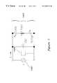
- FIG. 1An electrical model of a ultrasonic phacoemulsification probe in the vicinity of resonance is provided in FIG. 1 .
- the modelhas a voltage source 1401 connected to a 1130 picofarad capacitor 1402 connected in parallel to a series RLC circuit 1403 , wherein the resistor is 220 ohms, the inductor is 1.708 henrys, and the capacitor is 18 picofarads.
- resonant frequencyis defined herein as the frequency at which real power achieves a (local) maximum.
- apparent powermay be used to determine the resonant frequency if the parallel capacitance is compensated at resonance.
- Apparent powerprovides an approximation of resonant frequency (frequency at which the local maximum occurs) if a compensating inductor compensates parallel capacitance 1402 near resonance.
- the inventionis an improved phacoemulsification probe drive circuit for supplying electrical power to an ultrasonic transducer.
- the drive circuithas a power control loop and a frequency control loop.
- the power control loophas a variable gain amplifier whose output is an input to a power amplifier. After the power amplifier amplifies power, power is delivered to a transformer and, thereafter, to a transducer. The voltage and current applied to the primary of the transformer are sensed to generate a signal proportional to the power (real or apparent) and the result is compared against a power command originating from a foot pedal. Once compared, the result of this comparison is sent to a first controller which acts upon the information by sending a corrective signal to the variable gain amplifier.
- phase of the voltage and current waveforms applied to the primary of the transformerare sensed by a phase detector.
- the phase angleis then derived and compared against a phase command which is determined from the initial calibration of the system.
- the summer/difference blocksends its resulting comparison to a second controller which sends a control signal to the voltage controlled oscillator (VCO).
- VCOreceives the signal and sends a specific frequency at a fixed voltage to the variable gain amplifier.
- the phacoemulsification probeis calibrated by applying a constant voltage to the probe and sweeping the drive circuit through a series of frequencies. Then, a different voltage is selected and another frequency sweep is performed. This process is repeated for one or more voltage levels and the information on the power and phase versus frequency is stored in memory so that the optimal phase angle at resonance associated with a certain power requirement may be determined easily, although the phase angle may be relatively constant over a range of power levels.
- a range of frequencies about a certain resonant frequencyis used to create a window beyond which certain frequencies may not be used.
- a foot pedalis depressed providing a power command which is compared against the existing power.
- the difference between these two levelsis transmitted to the power loop controller.
- the power loop controllerselects the appropriate voltage level necessary to correct the difference between the power and the power command and sends this information to the control input of the variable gain amplifier.
- the variable gain amplifiersends its output to a power amplifier.
- the output of the power amplifieris applied to the transformer and simultaneously to both the power monitor and the phase detector.
- the poweris then calculated and compared against the power command signal received from the foot control and the power loop begins again.
- the phase detectorsends its phase information to a summer/difference block which compares the actual phase against a calculated phase command.
- phase commandis then sent to the frequency loop controller which communicates a signal to the voltage controlled oscillator to emit a certain frequency to the input of the variable gain amplifier which completes the frequency loop.
- the phase commandis determined from the information taken at calibration time and from the current power command.
- FIG. 1illustrates a block diagram of an electrical model of an ultrasonic phacoemulsification probe operating near its resonance frequency
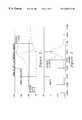
- FIG. 2is a graph of apparent power in accordance with the electrical model of FIG. 1;
- FIG. 3is a graph of the phase angle between the voltage and current waveforms relating to the apparent power graph of FIG. 2 and resulting from the electrical model of FIG. 1;
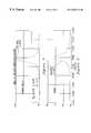
- FIG. 4is a graph of real power in accordance with the electrical model of FIG. 1;
- FIG. 5is a graph of the phase angle between the voltage and current waveforms relating to the real power graph of FIG. 4 and resulting from the electrical model of FIG. 1;
- FIG. 6is a graph of apparent power and phase angle with the addition of a compensating inductor to the electrical model of FIG. 5;
- FIG. 7is a graph of real power and phase angle with the addition of a compensating inductor to the electrical model of FIG. 5;
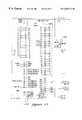
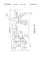
- FIG. 8illustrates a block diagram of the phacoemulsification probe system of the present invention
- FIG. 9illustrates a more detailed apparent power block diagram of the power monitor block in FIG. 8;
- FIG. 10illustrates a more detailed real power block diagram of the power monitor block in FIG. 8;
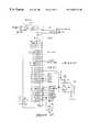
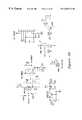
- FIGS. 11, 12 , 13 , 14 and 15illustrate a hardware-implemented embodiment of the present invention depicting a coprocessor and an electronically programmable logic device
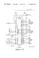
- FIGS. 16, 17 , 18 and 19illustrate a hardware-implemented embodiment of the present invention depicting memory for the coprocessor and a reset circuit
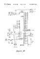
- FIGS. 20, 21 and 22illustrate a hardware-implemented embodiment of the present invention depicting a transceiver, and a neuron integrated circuit chip
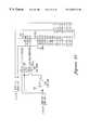
- FIGS. 23, 24 25 and 26illustrate a hardware-implemented embodiment of the present invention depicting a boost regulator, a voltage controlled oscillator, a multiplying digital to analog converter, a variable gain amplifier, a power amplifier, a first coupling capacitor, an isolating transformer, a second coupling capacitor, a compensating inductor, and an ultrasonic transducer;
- FIGS. 27 and 28illustrate a hardware-implemented embodiment of the present invention depicting voltage and current RMS to DC converters, and an average power detector;
- FIGS. 29 and 30illustrate a hardware-implemented embodiment of the present invention depicting various minor hardware aspects
- FIGS. 31 and 32illustrate a hardware-implemented embodiment of the present invention depicting various minor hardware aspects.
- FIG. 8shows the phacoemulsification probe system, shown generally at 1411 , of the present invention.
- Phacoemulsification probe system 1411comprises power loop shown generally at 1412 , frequency loop shown generally at 1413 , and isolated transducer circuit shown generally at 1414 .
- power loop 1412comprises power loop controller 1415 , variable gain amplifier 1416 , power amplifier 1417 , first coupling capacitor 1418 , transformer 1436 , power monitor 1419 , first summer/difference block 1425 , and power command signal input 1426 .
- Power loop controller 1415has an output to variable gain amplifier 1416 .
- the function of power loop controller 1415is twofold: (1) a perform a square root operation (power is proportional to the square of the voltage); and (2) to ensure loop stability and ensure desired system response characteristics.
- the power loop controller 1415can store in memory peak power information, although this can also be handled by a coprocessor and coprocessor memory combination.
- Power amplifier 1417receives an input from the output of variable gain amplifier 1416 .
- the output from power amplifier 1417proceeds through coupling capacitor 1418 which compensates for leakage inductance as well as blocks any direct current from power amplifier 1417 .
- Poweris then delivered to primary transformer 1436 and thence to isolated transducer circuit 1414 .
- the voltage and current applied to the isolated transducer circuit 1414are sensed by power monitor 1419 .
- Power monitor 1419generates a signal proportional to the power (real or apparent).
- power monitor 1419may be an apparent power monitor which comprises a voltage root mean square (RMS) to DC converter 1420 , current RMS to DC converter 1421 , and multiplier 1422 .
- a DC signal providing an apparent power valueis produced which is then communicated to first summer/difference block 1425 .
- power monitor 1419may be a real power monitor which comprises a voltage and current multiplier 1423 connected to low pass filter 1424 .
- a real power valueis produced with is then communicated to first summer/difference block 1425 .
- First summer/difference block 1425compares the power level detected by power monitor 1419 and the power command provided at power command signal input 1426 .
- any summer/difference block discussed hereinmay be embodied as a difference amplifier, and in software is commonly referred to as a “subtraction” operation.
- the results of the comparisonare communicated to power loop controller 1415 .
- a calculationis made on the magnitude of correction required, and power loop controller 1415 sends a new signal to voltage gain amplifier 1416 based on the calculation.
- the calculationmay be performed by power loop controller 1415 , or any other component associated with power loop controller 1415 such as a coprocessor and coprocessor memory. This completes one round of power loop 1412 .
- Frequency loop 1413comprises frequency loop controller 1430 which communicates a signal to voltage controlled oscillator 1431 which itself provides an input to variable gain amplifier 1416 , thence to power amplifier 1417 , through coupling capacitor 1418 , to isolated transducer circuit 1414 .
- the phase of the voltage and current waveforms applied to the isolated transducer circuit 1414are sensed by phase detector 1432 and then communicated to second summer/difference block 1433 .
- a phase commandwhich is determined from the initial calibration of the system and possibly from subsequent calculation is also communicated to phase command input 1434 of second summer/difference block 1433 .
- second summer/difference block 1433communicates an error signal based on the phase difference between the actual phase and the phase command to frequency loop controller 1430 .
- frequency loop controller 1430sends a new signal to voltage controlled oscillator 1431 based on the calculation.
- the calculationmay be performed by frequency loop controller 1430 , or any other component associated with power loop controller 1430 such as a coprocessor and coprocessor memory. This completes one iteration of frequency loop 1413 .
- isolated transducer circuit 1414comprises isolating secondary transformer 1436 , second coupling capacitor 1437 , compensating inductor 1438 , and ultrasonic transducer 1439 . More specifically, the parallel combination of ultrasonic transducer 1439 and compensating inductor 1438 is connected in series with the secondary of transformer 1436 and coupling capacitor 1437 . The function of second coupling capacitor 1437 is to compensate for any leakage inductance from isolating secondary transformer 1436 .
- the value of compensating inductor 1438is selected so that the magnitude of its reactance equals the magnitude of the reactance (C) of the parallel capacitance of ultrasonic transducer 1439 . If F represents the resonant frequency of the ultrasonic transducer, then the proper value of inductance to compensate the ultrasonic transducer is one divided by the quantity of the square of the quantity of two times pi times F, end quantity, times C, end quantity. In calculating the value of compensating inductor 1438 , it is commonly known that the values for ultrasonic transducer 1439 experience some amount of variation.
- a sampling of ultrasonic transducer 1439 partscan be made to derive the average value of parallel capacitance and thus to calculate the value of compensating inductor 1438 .
- compensating inductor 1438is a fixed value, it is known that this circuit is designed to provide for a relatively accurate inductor value to make phacoemulsification probe system 1401 appear to be purely resistive with the parallel combination of ultrasonic transducer 1439 and compensating inductor 1438 , with a small degree of error which is compensated by using power loop 1412 and frequency loop 1413 in combination.
- the phacoemulsification probe system 1411has two separate and distinct modes.
- One modeis calibration in which the control loops are opened, and the summer/difference blocks, 1425 and 1433 respectively, are removed, and the other is operation in which the control loops are closed so that a response may be given to a power command from a footpedal.
- a calibration of the entire system 1411must first be provided.
- the purpose of the calibration stepis to initialize a window of voltages and frequencies of operation of phacoemulsification probe system 1411 .
- the purpose of calibrationis to find an operational window of voltages and frequencies by successively iterating a series of frequencies at a constant voltage (sweeping the frequency), and then possibly repeating this for different voltages to derive the resonant frequency at various power levels.
- This informationis stored in memory and then is used to determine the phase commands in the control of the dual loop phacoemulsification probe system 1411 .
- Calibrationis initiated by a request from the user.
- calibrationconsists of one or more frequency sweeps.
- the frequencyis swept from a lower starting frequency to a higher end frequency by frequency loop controller 1430 .
- the excitation levelis kept constant by power loop controller 1415 .
- a command signal to calibrateis received by power loop controller 1415 and frequency loop controller 1427 .
- Power loop controller 1415then sends a command signal to variable gain amplifier 1416 such that variable gain amplifier will output a fixed voltage.
- frequency loop controller 1430sends a signal to voltage controlled oscillator 1431 .
- variable gain amplifier 1416Upon receipt of the signal from frequency loop controller 1430 , voltage controlled oscillator 1431 transmits a frequency sweep to variable gain amplifier 1416 .
- Variable gain amplifier 1416applies a voltage gain to the frequency sweep voltage to produce an output voltage. This output voltage is communicated as an input voltage to power amplifier 1417 .
- Power amplifier 1417amplifies the power and delivers the power to isolating secondary transformer 1436 via coupling capacitor 1418 (the operation of which was discussed previously).
- Power monitor 1419determines the frequency at which peak power achieves a local maximum, and phase detector 1432 determines the frequency where the phase crosses zero. A window of operating frequencies is then determined about this critical frequency.
- the back end of the windowis determined by first determining where the frequency achieves a local maximum peak power as well as a proximity to a zero phase angle crossing. From this area, the frequency sweep is examined at lower frequencies to determine the frequency at which a prior zero phase angle crossing occurred. From the frequency of this prior zero phase angle crossing, a fixed frequency amount is added to establish the back end of the operating frequency window.
- the forward end of the operating frequency windowmay be established in a similar way. Alternatively, a fixed frequency band such a 1 kHz may be established backward and forward of the critical frequency.
- the purpose of establishing a operational frequency windowis to ensure that the resonant frequency will occur within the operational frequency window, without encountering other zero phase crossings. Information on peak power, phase of peak power, operating power level, and the frequency window may be stored in memory.
- power loop controller 1415After sweeping the frequency, power loop controller 1415 changes the voltage gain and a different voltage (power/excitation level) is utilized to sweep the frequency, the phase and power information resulting therefrom being stored in memory. This data taken during calibration allows determination of varying phase angles so that a phase command may be determined during subsequent operation based upon the error signals derived from first summer/difference block 1425 and second summer/difference block 1433 during operation of the phacoemulsification probe system 1411 .
- phacoemulsification probe system 1411After the calibration of phacoemulsification probe system 1411 is completed, a process which may take between four to six seconds, the actual operation of phacoemulsification probe system 1411 as a phacoemulsification handpiece may commence.
- the surgeondepresses a foot pedal (not shown) which sends a power command to power command signal input 1426 of first summer/difference block 1425 .
- first summer/difference block 1425sends an error signal to power loop controller 1415 .
- Power loop controller 1415computes a new voltage requirement and sends a signal to variable gain amplifier 1416 .
- a phase command signal determined from the power command and the information stored during calibrationenters phase command signal input 1434 to second summer/difference block 1433 .
- Second summer/difference block 1433generates an error signal and communicates this signal to voltage controlled oscillator 1431 .
- Voltage controlled oscillator 1431outputs a changed frequency to an input of variable gain amplifier 1416 .
- variable gain amplifier 1416outputs a voltage to power amplifier 1417 which then delivers power to isolating secondary transformer 1436 .
- Isolating secondary transformer 1436delivers power through second coupling capacitor 1437 and compensating inductor 1438 to ultrasonic transducer 1439 .
- the voltage and current waveformsare communicated (in parallel with isolating secondary transformer 1436 ) to power monitor 1419 and to phase detector 1432 .
- the average power DC signalis received by first summer/difference block 1425 and compared against the existing power command provided at power command signal input 1426 .
- An error signalis then communicated from first summer/difference block 1425 to power loop controller 1415 .
- the phase angle from phase detector 1432is communicated to second summer/difference block 1433 and compared against phase command signal input 1434 and communicated to frequency loop controller 1430 .
- Power loop and frequency loop controllers, 1415 and 1430respectively, thereafter send corrective signals to variable gain amplifier 1416 , and variable controlled oscillator 1431 as described above.
- phase command signalis more likely than not a non-zero phase command because the final phacoemulsification probe system 1411 is very likely not exactly a purely resistive circuit.
- the reason that the system 1411 is very likely not a purely circuitis because compensating inductor 1438 has a fixed value which has a slight tolerance variation from unit to unit, and because the parallel capacitance of transducer 1439 may vary from handpiece to handpiece, and because environmental factors could cause the resonant frequency of ultrasonic transducer 1439 to change.
- the optimal phase angle ⁇ for a particular power levelis also non-zero.
- the phase angle ⁇is zero, the circuit is purely resistive. If there is an imbalance in the circuit, the phase angle cannot be zero because the circuit is not purely resistive. However, on average it is estimated that the optimal phase angle will generally be within at least twenty degrees of zero.
- FIGS. 11-32are provided first to simply enable the reader to prepare detailed circuit schematics of the block diagram shown in FIG. 8, and second to reveal the best mode of practicing the invention.
- the functions of power loop controller 1415 and frequency loop controller 1430are physically combined in hardware into one coprocessor 1441 shown in FIGS. 11 and 12.
- the coprocessor 1441 of FIGS. 11 and 12is connected to the voltage control oscillator 1431 shown in FIG. 23, a sign wave generator, which passes its signal to the variable gain amplifier 1416 , embodied in labelled LF 412 in combination with the multiplying digital to analog converter (MDAC), indicated by reference numeral 1444 .
- MDAC 1444is a two-channel DAC which passes a signal to boost regulator circuit shown in FIG.
- boost regulator circuit 24which provides the power supply and offset voltage to power amplifier 1417 shown in operational amplifier block labeled LM 12 in FIG. 25 .
- the boost regulator circuitis not required to effect the present invention.
- a boost regulator circuitis simply a different means for providing the supply voltage to power amplifier 1417 , and use of the circuit requires an additional controller to calculate the required boost voltage output and to send a boost command to the boost regulator.
- the output from power amplifier 1417is passed through coupling capacitor 1418 and thence to isolating transformer 1436 .
- current monitor lead 1446 and voltage monitor lead 1447are provided to sense the current and voltage delivered to isolating transformer 1436 .
- the monitor leads, 1446 and 1447 respectively, from FIG. 25are continued onto FIG. 27 wherein the monitor signals are scaled by operational amplifier blocks labelled LF 412 having numerical reference numerals 1448 and 1449 .
- the power monitor 1419senses the power delivered to first transformer (primary transformer) 1436 .
- voltage RMS to DC converter 1420is shown in block AD 536 and current RMS to DC converter 1421 is shown in similarly labelled block AD 536 .
- the outputsare communicated to an analog to digital converter shown in block MAX 182 (numbered 1450 ) which converts the sine wave signal to DC and thence to the coprocessor 1441 shown in FIG. 11 .
- phase detector 1432which is comprised of two parts: (1) the zero crossing detector operational amplifier shown in blocks labelled LM 319 (numbered 1451 and 1452 ) in FIG. 27; and (2) thence to FIG. 13 to the Electronically Programmable Logic Device (EPLD) 1453 shown in block PLSI 1032 .
- EPLDElectronically Programmable Logic Device
- the outputis transmitted to FIG. 27, the lead lag low pass filter shown in block LF 412 and thence to the analog to digital converter 1450 shown in block MAX 182 , and then to coprocessor 1441 shown in FIG. 11 .
- a NEURON chip 1454(NEURON is a registered trademark) is shown in block U 25 .
- This chiphas the following function. When the surgeon depresses the foot control, a communication from the foot control is transmitted transceiver 1455 shown in FIG. 22 block U 23 . Once the power command communication is received by transceiver 1455 , it is sent to NEURON chip 1454 in block U 25 , and then to the coprocessor 1441 shown in FIG. 11 .
- the power amplifiermay obtain an additional input from a boost regulator which can provide a power supply and an offset voltage with departure from the spirit of the present invention.
- the power loop controllermay send a signal to the third controller which then applies an input to the boost regulator whose output becomes one input for the power amplifier.
Landscapes
- Health & Medical Sciences (AREA)
- Ophthalmology & Optometry (AREA)
- Heart & Thoracic Surgery (AREA)
- Surgery (AREA)
- Engineering & Computer Science (AREA)
- Biomedical Technology (AREA)
- Nuclear Medicine, Radiotherapy & Molecular Imaging (AREA)
- Vascular Medicine (AREA)
- Life Sciences & Earth Sciences (AREA)
- Animal Behavior & Ethology (AREA)
- General Health & Medical Sciences (AREA)
- Public Health (AREA)
- Veterinary Medicine (AREA)
- Surgical Instruments (AREA)
Abstract
Description
Claims (3)
Priority Applications (1)
| Application Number | Priority Date | Filing Date | Title |
|---|---|---|---|
| US08/915,991US6203516B1 (en) | 1996-08-29 | 1997-08-21 | Phacoemulsification device and method for using dual loop frequency and power control |
Applications Claiming Priority (2)
| Application Number | Priority Date | Filing Date | Title |
|---|---|---|---|
| US2549896P | 1996-08-29 | 1996-08-29 | |
| US08/915,991US6203516B1 (en) | 1996-08-29 | 1997-08-21 | Phacoemulsification device and method for using dual loop frequency and power control |
Publications (1)
| Publication Number | Publication Date |
|---|---|
| US6203516B1true US6203516B1 (en) | 2001-03-20 |
Family
ID=26699815
Family Applications (1)
| Application Number | Title | Priority Date | Filing Date |
|---|---|---|---|
| US08/915,991Expired - LifetimeUS6203516B1 (en) | 1996-08-29 | 1997-08-21 | Phacoemulsification device and method for using dual loop frequency and power control |
Country Status (1)
| Country | Link |
|---|---|
| US (1) | US6203516B1 (en) |
Cited By (40)
| Publication number | Priority date | Publication date | Assignee | Title |
|---|---|---|---|---|
| US6325799B1 (en)* | 1997-04-24 | 2001-12-04 | Gyrus Medical Limited | Electrosurgical instrument |
| US20030097083A1 (en)* | 2001-11-20 | 2003-05-22 | Anderson David L. | Resonant converter tuning for maintaining substantially constant phaco handpiece power under increased load |
| US20040056719A1 (en)* | 2001-08-17 | 2004-03-25 | Dupuis Timothy J. | Method and apparatus for protecting devices in an RF power amplifier |
| US20040092921A1 (en)* | 2002-10-21 | 2004-05-13 | Kadziauskas Kenneth E. | System and method for pulsed ultrasonic power delivery employing cavitation effects |
| US20040092922A1 (en)* | 2002-10-21 | 2004-05-13 | Kadziauskas Kenneth E. | Modulated pulsed ultrasonic power delivery system and method |
| US20040174218A1 (en)* | 2003-03-04 | 2004-09-09 | Dupuis Timothy J. | Method and apparatus for controlling the output power of a power amplifier |
| US20040215127A1 (en)* | 1997-01-22 | 2004-10-28 | Kadziauskas Kenneth E. | Micro-burst ultrasonic power delivery |
| US20050024145A1 (en)* | 2002-12-03 | 2005-02-03 | Bocock Ryan M. | Fast settling power amplifier regulator |
| US20050054971A1 (en)* | 2003-07-14 | 2005-03-10 | Steen Mark E. | System and method for modulated surgical procedure irrigation and aspiration |
| US6917245B2 (en)* | 2000-09-12 | 2005-07-12 | Silicon Laboratories, Inc. | Absolute power detector |
| US7077820B1 (en) | 2002-10-21 | 2006-07-18 | Advanced Medical Optics, Inc. | Enhanced microburst ultrasonic power delivery system and method |
| US20060195077A1 (en)* | 2002-10-21 | 2006-08-31 | Advanced Medical Optics Inc. | System and method for pulsed ultrasonic power delivery employing cavitational effects |
| US7169123B2 (en) | 1997-01-22 | 2007-01-30 | Advanced Medical Optics, Inc. | Control of pulse duty cycle based upon footswitch displacement |
| US20070035203A1 (en)* | 2005-07-25 | 2007-02-15 | Piezolnnovations | Ultrasonic transducer control method and system |
| US20070113677A1 (en)* | 2005-10-24 | 2007-05-24 | Hydrometer Gmbh | Converter control with LC filtering |
| US20080033342A1 (en)* | 2006-08-01 | 2008-02-07 | Advanced Medical Optics, Inc. | Vacuum sense control for phaco pulse shaping |
| US20080061875A1 (en)* | 2006-09-08 | 2008-03-13 | Axiom Microdevices, Inc. | System and method for power amplifier output power control |
| US20080061874A1 (en)* | 2006-09-08 | 2008-03-13 | Axiom Microdevices, Inc. | System and method for power amplifier output power control |
| EP1905359A1 (en)* | 2006-06-30 | 2008-04-02 | Alcon, Inc. | System for dynamically adjusting operation of a surgical handpiece |
| US20080211584A1 (en)* | 2002-03-11 | 2008-09-04 | Seyed-Ali Hajimiri | Cross-differential amplifier |
| US20090015328A1 (en)* | 2007-07-11 | 2009-01-15 | Axiom Microdevices, Inc. | Low offset envelope detector and method of use |
| US7494468B2 (en) | 1999-10-05 | 2009-02-24 | Omnisonics Medical Technologies, Inc. | Ultrasonic medical device operating in a transverse mode |
| US7503895B2 (en) | 1999-10-05 | 2009-03-17 | Omnisonics Medical Technologies, Inc. | Ultrasonic device for tissue ablation and sheath for use therewith |
| WO2009036917A1 (en)* | 2007-09-13 | 2009-03-26 | Carl Zeiss Surgical Gmbh | Phacoemulsification device and method for operating the same |
| US7708734B2 (en) | 2006-06-30 | 2010-05-04 | Alcon, Inc. | Method for dynamically adjusting operation of a surgical handpiece |
| US7733183B2 (en) | 2000-10-10 | 2010-06-08 | California Institute Of Technology | Reconfigurable distributed active transformers |
| US20100145258A1 (en)* | 2008-12-08 | 2010-06-10 | David Hertweck | Systems and methods for eliminating post-excitation vibration in ophthalmic surgical handpieces |
| US7794414B2 (en) | 2004-02-09 | 2010-09-14 | Emigrant Bank, N.A. | Apparatus and method for an ultrasonic medical device operating in torsional and transverse modes |
| FR2948452A1 (en)* | 2009-07-24 | 2011-01-28 | Bosch Gmbh Robert | MEASUREMENT INSTALLATION WITH TELEMETRIC EXPLOITATION OF A SENSOR AND MEASUREMENT SYSTEM THUS EQUIPPED |
| US20110181297A1 (en)* | 2004-11-01 | 2011-07-28 | Cardiomems, Inc. | Communicating with an Implanted Wireless Sensor |
| US8049563B2 (en) | 2000-10-10 | 2011-11-01 | California Institute Of Technology | Distributed circular geometry power amplifier architecture |
| US20130334989A1 (en)* | 2012-06-15 | 2013-12-19 | Canon Kabushiki Kaisha | Driving device for vibration-type actuator and medical system using same |
| US8790359B2 (en) | 1999-10-05 | 2014-07-29 | Cybersonics, Inc. | Medical systems and related methods |
| US9050627B2 (en) | 2011-09-02 | 2015-06-09 | Abbott Medical Optics Inc. | Systems and methods for ultrasonic power measurement and control of phacoemulsification systems |
| USRE47399E1 (en)* | 2001-03-08 | 2019-05-21 | Maxim Integrated Products, Inc. | Method and apparatus for protecting radio frequency power amplifiers |
| EP3788995A1 (en)* | 2019-09-06 | 2021-03-10 | D.O.R.C. Dutch Ophthalmic Research Center (International) B.V. | A phaco driver system and a computer program product |
| US11844493B2 (en)* | 2016-11-17 | 2023-12-19 | Apyx Medical Corporation | Electrosurgical apparatus with dynamic leakage current compensation and dynamic RF modulation |
| US11877953B2 (en) | 2019-12-26 | 2024-01-23 | Johnson & Johnson Surgical Vision, Inc. | Phacoemulsification apparatus |
| US12178750B2 (en) | 2020-11-23 | 2024-12-31 | Johnson & Johnson Surgical Vision, Inc. | Removal of cataract debris |
| US12324770B2 (en) | 2021-04-15 | 2025-06-10 | Johnson & Johnson Surgical Vision, Inc. | Compensating for imperfect behavior of multi-piezoelectric crystal |
Citations (26)
| Publication number | Priority date | Publication date | Assignee | Title |
|---|---|---|---|---|
| US3693613A (en) | 1970-12-09 | 1972-09-26 | Cavitron Corp | Surgical handpiece and flow control system for use therewith |
| US3902495A (en) | 1974-01-28 | 1975-09-02 | Cavitron Corp | Flow control system |
| US3990452A (en) | 1975-06-13 | 1976-11-09 | Fibra-Sonics, Inc. | Medical machine for performing surgery and treating using ultrasonic energy |
| US4180074A (en) | 1977-03-15 | 1979-12-25 | Fibra-Sonics, Inc. | Device and method for applying precise irrigation, aspiration, medication, ultrasonic power and dwell time to biotissue for surgery and treatment |
| US4188927A (en) | 1978-01-12 | 1980-02-19 | Valleylab, Inc. | Multiple source electrosurgical generator |
| US4314560A (en) | 1979-11-28 | 1982-02-09 | Helfgott Maxwell A | Powered handpiece for endophthalmic surgery |
| US4378530A (en) | 1979-07-04 | 1983-03-29 | Unisearch Limited | High-efficiency low-distortion amplifier |
| US4428748A (en) | 1980-04-09 | 1984-01-31 | Peyman Gholam A | Combined ultrasonic emulsifier and mechanical cutter for surgery |
| US4504264A (en) | 1982-09-24 | 1985-03-12 | Kelman Charles D | Apparatus for and method of removal of material using ultrasonic vibraton |
| US4525775A (en) | 1982-11-01 | 1985-06-25 | Grigory Eydelman | Adaptive control system |
| US4587958A (en) | 1983-04-04 | 1986-05-13 | Sumitomo Bakelite Company Limited | Ultrasonic surgical device |
| US4793345A (en) | 1987-06-24 | 1988-12-27 | Lehmer Donald E | High voltage protection circuit for ultrasonic cataract remover |
| US4827911A (en) | 1986-04-02 | 1989-05-09 | Cooper Lasersonics, Inc. | Method and apparatus for ultrasonic surgical fragmentation and removal of tissue |
| US4868445A (en) | 1988-06-20 | 1989-09-19 | Wand Saul N | Self tuned ultrasonic generator system having wide frequency range and high efficiency |
| US4933843A (en) | 1986-11-06 | 1990-06-12 | Storz Instrument Company | Control system for ophthalmic surgical instruments |
| US5042460A (en) | 1988-10-25 | 1991-08-27 | Olympus Optical Co., Ltd. | Ultrasonic treating apparatus with device for inhibiting drive when ultrasonic element is determined to be defective |
| US5112300A (en) | 1990-04-03 | 1992-05-12 | Alcon Surgical, Inc. | Method and apparatus for controlling ultrasonic fragmentation of body tissue |
| US5121023A (en) | 1989-08-01 | 1992-06-09 | Ferton Holding | Ultrasonic generator with a piezoelectric converter |
| US5139509A (en) | 1989-08-25 | 1992-08-18 | Site Microsurgical Systems, Inc. | Phacoemulsification system with handpiece simulator |
| US5151085A (en) | 1989-04-28 | 1992-09-29 | Olympus Optical Co., Ltd. | Apparatus for generating ultrasonic oscillation |
| US5220272A (en) | 1990-09-10 | 1993-06-15 | Linear Technology Corporation | Switching regulator with asymmetrical feedback amplifier and method |
| US5331951A (en) | 1992-09-04 | 1994-07-26 | American Cyanamid Company | Phacoemulsification probe drive circuit |
| US5370602A (en) | 1992-09-04 | 1994-12-06 | American Cyanamid Company | Phacoemulsification probe circuit with pulse width Modulating drive |
| US5388569A (en) | 1992-09-04 | 1995-02-14 | American Cyanamid Co | Phacoemulsification probe circuit with switch drive |
| US5406503A (en) | 1989-10-27 | 1995-04-11 | American Cyanamid Company | Control system for calibrating and driving ultrasonic transducer |
| US5455766A (en) | 1986-11-06 | 1995-10-03 | Storz Instrument Company | Control system for ophthalmic surgical instruments |
- 1997
- 1997-08-21USUS08/915,991patent/US6203516B1/ennot_activeExpired - Lifetime
Patent Citations (26)
| Publication number | Priority date | Publication date | Assignee | Title |
|---|---|---|---|---|
| US3693613A (en) | 1970-12-09 | 1972-09-26 | Cavitron Corp | Surgical handpiece and flow control system for use therewith |
| US3902495A (en) | 1974-01-28 | 1975-09-02 | Cavitron Corp | Flow control system |
| US3990452A (en) | 1975-06-13 | 1976-11-09 | Fibra-Sonics, Inc. | Medical machine for performing surgery and treating using ultrasonic energy |
| US4180074A (en) | 1977-03-15 | 1979-12-25 | Fibra-Sonics, Inc. | Device and method for applying precise irrigation, aspiration, medication, ultrasonic power and dwell time to biotissue for surgery and treatment |
| US4188927A (en) | 1978-01-12 | 1980-02-19 | Valleylab, Inc. | Multiple source electrosurgical generator |
| US4378530A (en) | 1979-07-04 | 1983-03-29 | Unisearch Limited | High-efficiency low-distortion amplifier |
| US4314560A (en) | 1979-11-28 | 1982-02-09 | Helfgott Maxwell A | Powered handpiece for endophthalmic surgery |
| US4428748A (en) | 1980-04-09 | 1984-01-31 | Peyman Gholam A | Combined ultrasonic emulsifier and mechanical cutter for surgery |
| US4504264A (en) | 1982-09-24 | 1985-03-12 | Kelman Charles D | Apparatus for and method of removal of material using ultrasonic vibraton |
| US4525775A (en) | 1982-11-01 | 1985-06-25 | Grigory Eydelman | Adaptive control system |
| US4587958A (en) | 1983-04-04 | 1986-05-13 | Sumitomo Bakelite Company Limited | Ultrasonic surgical device |
| US4827911A (en) | 1986-04-02 | 1989-05-09 | Cooper Lasersonics, Inc. | Method and apparatus for ultrasonic surgical fragmentation and removal of tissue |
| US4933843A (en) | 1986-11-06 | 1990-06-12 | Storz Instrument Company | Control system for ophthalmic surgical instruments |
| US5455766A (en) | 1986-11-06 | 1995-10-03 | Storz Instrument Company | Control system for ophthalmic surgical instruments |
| US4793345A (en) | 1987-06-24 | 1988-12-27 | Lehmer Donald E | High voltage protection circuit for ultrasonic cataract remover |
| US4868445A (en) | 1988-06-20 | 1989-09-19 | Wand Saul N | Self tuned ultrasonic generator system having wide frequency range and high efficiency |
| US5042460A (en) | 1988-10-25 | 1991-08-27 | Olympus Optical Co., Ltd. | Ultrasonic treating apparatus with device for inhibiting drive when ultrasonic element is determined to be defective |
| US5151085A (en) | 1989-04-28 | 1992-09-29 | Olympus Optical Co., Ltd. | Apparatus for generating ultrasonic oscillation |
| US5121023A (en) | 1989-08-01 | 1992-06-09 | Ferton Holding | Ultrasonic generator with a piezoelectric converter |
| US5139509A (en) | 1989-08-25 | 1992-08-18 | Site Microsurgical Systems, Inc. | Phacoemulsification system with handpiece simulator |
| US5406503A (en) | 1989-10-27 | 1995-04-11 | American Cyanamid Company | Control system for calibrating and driving ultrasonic transducer |
| US5112300A (en) | 1990-04-03 | 1992-05-12 | Alcon Surgical, Inc. | Method and apparatus for controlling ultrasonic fragmentation of body tissue |
| US5220272A (en) | 1990-09-10 | 1993-06-15 | Linear Technology Corporation | Switching regulator with asymmetrical feedback amplifier and method |
| US5331951A (en) | 1992-09-04 | 1994-07-26 | American Cyanamid Company | Phacoemulsification probe drive circuit |
| US5370602A (en) | 1992-09-04 | 1994-12-06 | American Cyanamid Company | Phacoemulsification probe circuit with pulse width Modulating drive |
| US5388569A (en) | 1992-09-04 | 1995-02-14 | American Cyanamid Co | Phacoemulsification probe circuit with switch drive |
Cited By (108)
| Publication number | Priority date | Publication date | Assignee | Title |
|---|---|---|---|---|
| US20040215127A1 (en)* | 1997-01-22 | 2004-10-28 | Kadziauskas Kenneth E. | Micro-burst ultrasonic power delivery |
| US8197436B2 (en) | 1997-01-22 | 2012-06-12 | Abbott Medical Optics Inc. | Micro-burst ultrasonic power delivery |
| US7169123B2 (en) | 1997-01-22 | 2007-01-30 | Advanced Medical Optics, Inc. | Control of pulse duty cycle based upon footswitch displacement |
| US20070073309A1 (en)* | 1997-01-22 | 2007-03-29 | Advanced Medical Optics, Inc. | Control of pulse duty cycle based upon footswitch displacement |
| US20070118071A1 (en)* | 1997-01-22 | 2007-05-24 | Advanced Medical Optics, Inc. | Micro-burst ultrasonic power delivery |
| US8876747B2 (en) | 1997-01-22 | 2014-11-04 | Abbott Medical Optics Inc. | Micro-burst ultrasonic power delivery |
| US7857783B2 (en) | 1997-01-22 | 2010-12-28 | Abbott Medical Optics Inc. | Micro-burst ultrasonic power delivery |
| US20110160646A1 (en)* | 1997-01-22 | 2011-06-30 | Abbott Medical Optics Inc. | Micro-burst ultrasonic power delivery |
| US7485106B2 (en) | 1997-01-22 | 2009-02-03 | Advanced Medical Optics, Inc. | Micro-burst ultrasonic power delivery |
| US9788998B2 (en) | 1997-01-22 | 2017-10-17 | Abbott Medical Optics Inc. | Control of pulse duty cycle based upon footswitch displacement |
| US8195286B2 (en) | 1997-01-22 | 2012-06-05 | Abbott Medical Optics Inc. | Control of pulse duty cycle based upon footswitch displacement |
| US6325799B1 (en)* | 1997-04-24 | 2001-12-04 | Gyrus Medical Limited | Electrosurgical instrument |
| US7503895B2 (en) | 1999-10-05 | 2009-03-17 | Omnisonics Medical Technologies, Inc. | Ultrasonic device for tissue ablation and sheath for use therewith |
| US8790359B2 (en) | 1999-10-05 | 2014-07-29 | Cybersonics, Inc. | Medical systems and related methods |
| US7494468B2 (en) | 1999-10-05 | 2009-02-24 | Omnisonics Medical Technologies, Inc. | Ultrasonic medical device operating in a transverse mode |
| US6917245B2 (en)* | 2000-09-12 | 2005-07-12 | Silicon Laboratories, Inc. | Absolute power detector |
| US7733183B2 (en) | 2000-10-10 | 2010-06-08 | California Institute Of Technology | Reconfigurable distributed active transformers |
| US8049563B2 (en) | 2000-10-10 | 2011-11-01 | California Institute Of Technology | Distributed circular geometry power amplifier architecture |
| USRE47399E1 (en)* | 2001-03-08 | 2019-05-21 | Maxim Integrated Products, Inc. | Method and apparatus for protecting radio frequency power amplifiers |
| US7145396B2 (en) | 2001-08-17 | 2006-12-05 | Silicon Laboratories, Inc. | Method and apparatus for protecting devices in an RF power amplifier |
| US6828859B2 (en) | 2001-08-17 | 2004-12-07 | Silicon Laboratories, Inc. | Method and apparatus for protecting devices in an RF power amplifier |
| US20040070457A1 (en)* | 2001-08-17 | 2004-04-15 | Dupuis Timothy J. | Method and apparatus for protecting devices in an RF power amplifier |
| US20040056719A1 (en)* | 2001-08-17 | 2004-03-25 | Dupuis Timothy J. | Method and apparatus for protecting devices in an RF power amplifier |
| US6997935B2 (en) | 2001-11-20 | 2006-02-14 | Advanced Medical Optics, Inc. | Resonant converter tuning for maintaining substantially constant phaco handpiece power under increased load |
| WO2003043550A1 (en)* | 2001-11-20 | 2003-05-30 | Advanced Medical Optics, Inc. | Phase driven power controller for phacoemulsification handpiece |
| US20030097083A1 (en)* | 2001-11-20 | 2003-05-22 | Anderson David L. | Resonant converter tuning for maintaining substantially constant phaco handpiece power under increased load |
| US20080211584A1 (en)* | 2002-03-11 | 2008-09-04 | Seyed-Ali Hajimiri | Cross-differential amplifier |
| US7999621B2 (en) | 2002-03-11 | 2011-08-16 | California Institute Of Technology | Cross-differential amplifier |
| US8362839B2 (en) | 2002-03-11 | 2013-01-29 | California Institute Of Technology | Cross-differential amplifier |
| US20100117733A1 (en)* | 2002-03-11 | 2010-05-13 | California Institute Of Technology | Cross-differential amplifier |
| US7646249B2 (en) | 2002-03-11 | 2010-01-12 | California Institute Of Technology | Cross-differential amplifier |
| US7938120B2 (en) | 2002-10-21 | 2011-05-10 | Abbott Medical Optics, Inc. | Enhanced microburst ultrasonic power delivery system and method |
| US8945162B2 (en) | 2002-10-21 | 2015-02-03 | Abbott Medical Optics Inc. | System and method for pulsed ultrasonic power delivery employing cavitational effects |
| US8887735B2 (en) | 2002-10-21 | 2014-11-18 | Abbott Medical Optics Inc. | Modulated pulsed ultrasonic power delivery system and method |
| US20040092921A1 (en)* | 2002-10-21 | 2004-05-13 | Kadziauskas Kenneth E. | System and method for pulsed ultrasonic power delivery employing cavitation effects |
| US20080108938A1 (en)* | 2002-10-21 | 2008-05-08 | Advanced Medical Optics, Inc. | Modulated Pulsed ultrasonic power delivery system and method |
| US8852138B2 (en) | 2002-10-21 | 2014-10-07 | Abbott Medical Optics Inc. | Modulated pulsed ultrasound power delivery system and method |
| US20040092922A1 (en)* | 2002-10-21 | 2004-05-13 | Kadziauskas Kenneth E. | Modulated pulsed ultrasonic power delivery system and method |
| US7842005B2 (en) | 2002-10-21 | 2010-11-30 | Abbott Medical Optics, Inc. | System and method for pulsed ultrasonic power delivery employing cavitational effects |
| US20080058799A1 (en)* | 2002-10-21 | 2008-03-06 | Advanced Medical Optics, Inc. | Modulated pulsed ultrasonic power delivery system and method |
| US20060195077A1 (en)* | 2002-10-21 | 2006-08-31 | Advanced Medical Optics Inc. | System and method for pulsed ultrasonic power delivery employing cavitational effects |
| US7316664B2 (en) | 2002-10-21 | 2008-01-08 | Advanced Medical Optics, Inc. | Modulated pulsed ultrasonic power delivery system and method |
| US10765557B2 (en) | 2002-10-21 | 2020-09-08 | Johnson & Johnson Surgical Vision, Inc. | Modulated pulsed ultrasonic power delivery system and method |
| US9642745B2 (en) | 2002-10-21 | 2017-05-09 | Abbott Medical Optics Inc. | Modulated pulsed ultrasonic power delivery system and method |
| US8231564B2 (en) | 2002-10-21 | 2012-07-31 | Abbott Medical Optics Inc. | Modulated pulsed ultrasonic power delivery system and method |
| US10245179B2 (en) | 2002-10-21 | 2019-04-02 | Johnson & Johnson Surgical Vision, Inc. | System and method for pulsed ultrasonic power delivery employing cavitation effects |
| US9707127B2 (en) | 2002-10-21 | 2017-07-18 | Abbott Medical Optics Inc. | Modulated pulsed ultrasonic power delivery system and method |
| US8020565B2 (en) | 2002-10-21 | 2011-09-20 | Abbott Medical Optics, Inc. | Modulated pulsed ultrasonic power delivery system and method |
| US20110077583A1 (en)* | 2002-10-21 | 2011-03-31 | Abbott Medical Optics Inc. | System and method for pulsed ultrasonic power delivery employing cavitational effects |
| US7077820B1 (en) | 2002-10-21 | 2006-07-18 | Advanced Medical Optics, Inc. | Enhanced microburst ultrasonic power delivery system and method |
| US20060200068A1 (en)* | 2002-10-21 | 2006-09-07 | Advanced Medical Optics, Inc. | Novel enhanced microburst ultrasonic power delivery system and method |
| US6894565B1 (en) | 2002-12-03 | 2005-05-17 | Silicon Laboratories, Inc. | Fast settling power amplifier regulator |
| US7173491B2 (en) | 2002-12-03 | 2007-02-06 | Silicon Laboratories Inc. | Fast settling power amplifier regulator |
| US20050024145A1 (en)* | 2002-12-03 | 2005-02-03 | Bocock Ryan M. | Fast settling power amplifier regulator |
| US6897730B2 (en) | 2003-03-04 | 2005-05-24 | Silicon Laboratories Inc. | Method and apparatus for controlling the output power of a power amplifier |
| US7106137B2 (en) | 2003-03-04 | 2006-09-12 | Silicon Laboratories Inc. | Method and apparatus for controlling the output power of a power amplifier |
| US20050030100A1 (en)* | 2003-03-04 | 2005-02-10 | Dupuis Timothy J. | Method and apparatus for controlling the output power of a power amplifier |
| US20040174218A1 (en)* | 2003-03-04 | 2004-09-09 | Dupuis Timothy J. | Method and apparatus for controlling the output power of a power amplifier |
| US20050054971A1 (en)* | 2003-07-14 | 2005-03-10 | Steen Mark E. | System and method for modulated surgical procedure irrigation and aspiration |
| US8814821B2 (en) | 2003-07-14 | 2014-08-26 | Abbott Medical Optics Inc. | System and method for modulated surgical procedure irrigation and aspiration |
| US7846126B2 (en) | 2003-07-14 | 2010-12-07 | Abbott Medical Optics, Inc. | System and method for modulated surgical procedure irrigation and aspiration |
| US20100094199A1 (en)* | 2003-07-14 | 2010-04-15 | Abbott Medical Optics Incorporated | System and method for modulated surgical procedure irrigation and aspiration |
| US20110071460A1 (en)* | 2003-07-14 | 2011-03-24 | Abbott Medical Optics Inc. | System and method for modulated surgical procedure irrigation and aspiration |
| US9545334B2 (en) | 2003-07-14 | 2017-01-17 | Abbott Medical Optics, Inc. | System and method for modulated surgical procedure irrigation and aspiration |
| US7794414B2 (en) | 2004-02-09 | 2010-09-14 | Emigrant Bank, N.A. | Apparatus and method for an ultrasonic medical device operating in torsional and transverse modes |
| US20110181297A1 (en)* | 2004-11-01 | 2011-07-28 | Cardiomems, Inc. | Communicating with an Implanted Wireless Sensor |
| US8237451B2 (en)* | 2004-11-01 | 2012-08-07 | Cardiomems, Inc. | Communicating with an implanted wireless sensor |
| US20070035203A1 (en)* | 2005-07-25 | 2007-02-15 | Piezolnnovations | Ultrasonic transducer control method and system |
| US7554343B2 (en) | 2005-07-25 | 2009-06-30 | Piezoinnovations | Ultrasonic transducer control method and system |
| US7366057B2 (en)* | 2005-10-24 | 2008-04-29 | Hydrometer Gmbh | Converter control with LC filtering |
| US20070113677A1 (en)* | 2005-10-24 | 2007-05-24 | Hydrometer Gmbh | Converter control with LC filtering |
| US20080122407A1 (en)* | 2006-06-30 | 2008-05-29 | Alcon, Inc. | System for dynamically adjusting operation of a surgical handpiece |
| US7640119B2 (en) | 2006-06-30 | 2009-12-29 | Alcon, Inc. | System for dynamically adjusting operation of a surgical handpiece |
| US7708734B2 (en) | 2006-06-30 | 2010-05-04 | Alcon, Inc. | Method for dynamically adjusting operation of a surgical handpiece |
| EP1905359A1 (en)* | 2006-06-30 | 2008-04-02 | Alcon, Inc. | System for dynamically adjusting operation of a surgical handpiece |
| US8366728B2 (en) | 2006-08-01 | 2013-02-05 | Abbott Medical Optics Inc. | Vacuum sense control for phaco pulse shaping |
| US7998156B2 (en) | 2006-08-01 | 2011-08-16 | Abbott Medical Optics Inc. | Vacuum sense control for phaco pulse shaping |
| US7785336B2 (en) | 2006-08-01 | 2010-08-31 | Abbott Medical Optics Inc. | Vacuum sense control for phaco pulse shaping |
| US8034067B2 (en) | 2006-08-01 | 2011-10-11 | Abbott Medical Optics Inc. | Vacuum sense control for phaco pulse shaping |
| US20080033342A1 (en)* | 2006-08-01 | 2008-02-07 | Advanced Medical Optics, Inc. | Vacuum sense control for phaco pulse shaping |
| US20100114010A1 (en)* | 2006-08-01 | 2010-05-06 | Abbott Medical Optics Inc. | Vacuum sense control for phaco pulse shaping |
| US20100114009A1 (en)* | 2006-08-01 | 2010-05-06 | Abbott Medical Optics Inc. | Vacuum sense control for phaco pulse shaping |
| US8202287B2 (en) | 2006-08-01 | 2012-06-19 | Abbott Medical Optics Inc. | Vacuum sense control for phaco pulse shaping |
| US9226849B2 (en) | 2006-08-01 | 2016-01-05 | Abbott Medical Optics Inc. | Vacuum sense control for phaco pulse shaping |
| US20080061875A1 (en)* | 2006-09-08 | 2008-03-13 | Axiom Microdevices, Inc. | System and method for power amplifier output power control |
| US7733176B2 (en)* | 2006-09-08 | 2010-06-08 | Infineon Technologies Ag | System and method for power amplifier output power control |
| US20080061874A1 (en)* | 2006-09-08 | 2008-03-13 | Axiom Microdevices, Inc. | System and method for power amplifier output power control |
| US20090015328A1 (en)* | 2007-07-11 | 2009-01-15 | Axiom Microdevices, Inc. | Low offset envelope detector and method of use |
| US7710197B2 (en) | 2007-07-11 | 2010-05-04 | Axiom Microdevices, Inc. | Low offset envelope detector and method of use |
| RU2484797C2 (en)* | 2007-09-13 | 2013-06-20 | Карл Цайсс Медитек Аг | Device of phacoemulcification and method of its exploitation |
| WO2009036917A1 (en)* | 2007-09-13 | 2009-03-26 | Carl Zeiss Surgical Gmbh | Phacoemulsification device and method for operating the same |
| EP2187851B1 (en) | 2007-09-13 | 2016-06-22 | Carl Zeiss Meditec AG | Phacoemulsification device |
| US8277462B2 (en) | 2007-09-13 | 2012-10-02 | Carl Zeiss Meditec Ag | Phacoemulsification device and method for operating the same |
| US20100241131A1 (en)* | 2007-09-13 | 2010-09-23 | Carl Zeiss Surgical Gmbh | Phacoemulsification device and method for operating the same |
| WO2010077575A1 (en)* | 2008-12-08 | 2010-07-08 | Bausch & Lomb Incorporated | Systems and methods for eliminating post-excitation vibration in ophthalmic surgical handpieces |
| US20100145258A1 (en)* | 2008-12-08 | 2010-06-10 | David Hertweck | Systems and methods for eliminating post-excitation vibration in ophthalmic surgical handpieces |
| FR2948452A1 (en)* | 2009-07-24 | 2011-01-28 | Bosch Gmbh Robert | MEASUREMENT INSTALLATION WITH TELEMETRIC EXPLOITATION OF A SENSOR AND MEASUREMENT SYSTEM THUS EQUIPPED |
| US9050627B2 (en) | 2011-09-02 | 2015-06-09 | Abbott Medical Optics Inc. | Systems and methods for ultrasonic power measurement and control of phacoemulsification systems |
| US20130334989A1 (en)* | 2012-06-15 | 2013-12-19 | Canon Kabushiki Kaisha | Driving device for vibration-type actuator and medical system using same |
| CN103516254A (en)* | 2012-06-15 | 2014-01-15 | 佳能株式会社 | Driving device for vibration-type actuator and medical system using same |
| CN103516254B (en)* | 2012-06-15 | 2015-12-23 | 佳能株式会社 | For vibration-type actuator drive unit and use its medical system |
| US11844493B2 (en)* | 2016-11-17 | 2023-12-19 | Apyx Medical Corporation | Electrosurgical apparatus with dynamic leakage current compensation and dynamic RF modulation |
| EP3788995A1 (en)* | 2019-09-06 | 2021-03-10 | D.O.R.C. Dutch Ophthalmic Research Center (International) B.V. | A phaco driver system and a computer program product |
| NL2023788B1 (en)* | 2019-09-06 | 2021-05-17 | D O R C Dutch Ophthalmic Res Center International B V | A phaco driver system, a method and a computer program product |
| US12076749B2 (en) | 2019-09-06 | 2024-09-03 | D.O.R.C. Dutch Ophthalmic Research Center (International) B.V. | Phaco driver system, a method and a computer program product |
| US11877953B2 (en) | 2019-12-26 | 2024-01-23 | Johnson & Johnson Surgical Vision, Inc. | Phacoemulsification apparatus |
| US12178750B2 (en) | 2020-11-23 | 2024-12-31 | Johnson & Johnson Surgical Vision, Inc. | Removal of cataract debris |
| US12324770B2 (en) | 2021-04-15 | 2025-06-10 | Johnson & Johnson Surgical Vision, Inc. | Compensating for imperfect behavior of multi-piezoelectric crystal |
Similar Documents
| Publication | Publication Date | Title |
|---|---|---|
| US6203516B1 (en) | Phacoemulsification device and method for using dual loop frequency and power control | |
| CA2264663C (en) | Dual loop frequency and power control | |
| US6761690B2 (en) | Ultrasonic operation apparatus for performing follow-up control of resonance frequency drive of ultrasonic oscillator by digital PLL system using DDS (direct digital synthesizer) | |
| AU2022202452B2 (en) | System and method for driving an ultrasonic handpiece as a function of the mechanical impedance of the handpiece | |
| US4954960A (en) | Linear power control for ultrasonic probe with tuned reactance | |
| US5184605A (en) | Therapeutic ultrasound generator with radiation dose control | |
| US20210353326A1 (en) | Temperature estimation and tissue detection of an ultrasonic dissector from frequency response monitoring | |
| US4970656A (en) | Analog drive for ultrasonic probe with tunable phase angle | |
| US6228079B1 (en) | Method and apparatus for power measurement in radio frequency electro-surgical generators | |
| US20190274752A1 (en) | Fine dissection mode for tissue classification | |
| US7554341B2 (en) | Method and measurement apparatus for determining the transition impedance between two parts of a subdivided neutral electrode | |
| JP3026833B2 (en) | Driving device for ultrasonic transducer and device for automatically determining resonance frequency | |
| JPH03123548A (en) | Linear electric power control for supersonic prove with tuning-reactance | |
| US7927300B2 (en) | Ultrasonic operation apparatus for detecting initial resonance frequency and for shifting to PLL operation | |
| US20090157067A1 (en) | Method and apparatus for digital signal processing for radio frequency surgery measurements | |
| JP2916527B2 (en) | Ultrasonic generator | |
| US20200345406A1 (en) | Generator | |
| US6394974B1 (en) | Power mode phaco | |
| JPH01251213A (en) | High frequency power generator | |
| JP2002513325A (en) | Multi-frequency phase detector for ultrasonic cataract emulsification suction method | |
| CN115040200A (en) | Ultrasonic surgical tool, frequency tracking method thereof, target phase difference determination method thereof and ultrasonic transducer equivalent circuit | |
| US8009508B2 (en) | Ultrasonic generator system | |
| US20240383004A1 (en) | Phaco driver system, a method and a computer program product | |
| JP7429811B2 (en) | Surgical generator with improved drive for ultrasonic surgical instruments | |
| MXPA99001860A (en) | Dual loop frequency and power control |
Legal Events
| Date | Code | Title | Description |
|---|---|---|---|
| AS | Assignment | Owner name:STORZ INSTRUMENT COMPANY, MISSOURI Free format text:ASSIGNMENT OF ASSIGNORS INTEREST;ASSIGNOR:KEPLEY, KEVIN PAUL;REEL/FRAME:008812/0011 Effective date:19970821 | |
| AS | Assignment | Owner name:BAUSCH & LOMB SURGICAL, INC., CALIFORNIA Free format text:CHANGE OF NAME;ASSIGNOR:STORZ INSTRUMENT COMPANY;REEL/FRAME:011312/0267 Effective date:19980613 | |
| STCF | Information on status: patent grant | Free format text:PATENTED CASE | |
| FPAY | Fee payment | Year of fee payment:4 | |
| AS | Assignment | Owner name:CREDIT SUISSE, NEW YORK Free format text:SECURITY AGREEMENT;ASSIGNORS:BAUSCH & LOMB INCORPORATED;WP PRISM INC.;B&L CRL INC.;AND OTHERS;REEL/FRAME:020733/0765 Effective date:20080320 Owner name:CREDIT SUISSE,NEW YORK Free format text:SECURITY AGREEMENT;ASSIGNORS:BAUSCH & LOMB INCORPORATED;WP PRISM INC.;B&L CRL INC.;AND OTHERS;REEL/FRAME:020733/0765 Effective date:20080320 | |
| FPAY | Fee payment | Year of fee payment:8 | |
| AS | Assignment | Owner name:BAUSCH & LOMB INCORPORATED, NEW YORK Free format text:RELEASE BY SECURED PARTY;ASSIGNOR:CREDIT SUISSE AG, CAYMAN ISLANDS BRANCH;REEL/FRAME:028726/0142 Effective date:20120518 | |
| AS | Assignment | Owner name:CITIBANK N.A., AS ADMINISTRATIVE AGENT, DELAWARE Free format text:SECURITY AGREEMENT;ASSIGNORS:BAUSCH & LOMB INCORPORATED;EYEONICS, INC.;REEL/FRAME:028728/0645 Effective date:20120518 | |
| FPAY | Fee payment | Year of fee payment:12 | |
| AS | Assignment | Owner name:BAUSCH & LOMB INCORPORATED, NEW YORK Free format text:MERGER;ASSIGNOR:BAUSCH & LOMB SURGICAL, INC.;REEL/FRAME:030522/0865 Effective date:20010331 | |
| AS | Assignment | Owner name:WP PRISM INC. (N/K/A BAUSCH & LOMB HOLDINGS INC.), NEW YORK Free format text:RELEASE OF SECURITY INTEREST;ASSIGNOR:CITIBANK N.A., AS ADMINISTRATIVE AGENT;REEL/FRAME:030995/0444 Effective date:20130805 Owner name:WP PRISM INC. (N/K/A BAUSCH & LOMB HOLDINGS INC.), Free format text:RELEASE OF SECURITY INTEREST;ASSIGNOR:CITIBANK N.A., AS ADMINISTRATIVE AGENT;REEL/FRAME:030995/0444 Effective date:20130805 Owner name:BAUSCH & LOMB INCORPORATED, NEW YORK Free format text:RELEASE OF SECURITY INTEREST;ASSIGNOR:CITIBANK N.A., AS ADMINISTRATIVE AGENT;REEL/FRAME:030995/0444 Effective date:20130805 Owner name:ISTA PHARMACEUTICALS, NEW YORK Free format text:RELEASE OF SECURITY INTEREST;ASSIGNOR:CITIBANK N.A., AS ADMINISTRATIVE AGENT;REEL/FRAME:030995/0444 Effective date:20130805 | |
| AS | Assignment | Owner name:GOLDMAN SACHS LENDING PARTNERS LLC, AS COLLATERAL AGENT, NEW YORK Free format text:SECURITY AGREEMENT;ASSIGNOR:BAUSCH & LOMB INCORPORATED;REEL/FRAME:031156/0508 Effective date:20130830 Owner name:GOLDMAN SACHS LENDING PARTNERS LLC, AS COLLATERAL Free format text:SECURITY AGREEMENT;ASSIGNOR:BAUSCH & LOMB INCORPORATED;REEL/FRAME:031156/0508 Effective date:20130830 | |
| AS | Assignment | Owner name:BARCLAYS BANK PLC, AS SUCCESSOR AGENT, NEW YORK Free format text:NOTICE OF SUCCESSION OF AGENCY;ASSIGNOR:GOLDMAN SACHS LENDING PARTNERS, LLC;REEL/FRAME:034749/0689 Effective date:20150108 | |
| AS | Assignment | Owner name:THE BANK OF NEW YORK MELLON, NEW YORK Free format text:SECURITY INTEREST;ASSIGNOR:BAUSCH & LOMB INCORPORATED;REEL/FRAME:043251/0932 Effective date:20170717 | |
| AS | Assignment | Owner name:1530065 B.C. LTD., CANADA Free format text:RELEASE BY SECURED PARTY;ASSIGNOR:BARCLAYS BANK PLC, AS COLLATERAL AGENT;REEL/FRAME:070778/0199 Effective date:20250408 Owner name:1261229 B.C. LTD., CANADA Free format text:RELEASE BY SECURED PARTY;ASSIGNOR:BARCLAYS BANK PLC, AS COLLATERAL AGENT;REEL/FRAME:070778/0199 Effective date:20250408 Owner name:VRX HOLDCO LLC, NEW JERSEY Free format text:RELEASE BY SECURED PARTY;ASSIGNOR:BARCLAYS BANK PLC, AS COLLATERAL AGENT;REEL/FRAME:070778/0199 Effective date:20250408 Owner name:V-BAC HOLDING CORP., CANADA Free format text:RELEASE BY SECURED PARTY;ASSIGNOR:BARCLAYS BANK PLC, AS COLLATERAL AGENT;REEL/FRAME:070778/0199 Effective date:20250408 Owner name:SOLTA MEDICAL DUTCH HOLDINGS B.V., NETHERLANDS Free format text:RELEASE BY SECURED PARTY;ASSIGNOR:BARCLAYS BANK PLC, AS COLLATERAL AGENT;REEL/FRAME:070778/0199 Effective date:20250408 Owner name:PRZEDSIEBIORSTWO FARMACEUTYCZNE JELFA SPOLKA AKCYJNA (A/K/A PRZEDSIEBIORSTWO FARMACEUTYCZNE JELFA S.A.), POLAND Free format text:RELEASE BY SECURED PARTY;ASSIGNOR:BARCLAYS BANK PLC, AS COLLATERAL AGENT;REEL/FRAME:070778/0199 Effective date:20250408 Owner name:ORAPHARMA, INC., NEW JERSEY Free format text:RELEASE BY SECURED PARTY;ASSIGNOR:BARCLAYS BANK PLC, AS COLLATERAL AGENT;REEL/FRAME:070778/0199 Effective date:20250408 Owner name:ICN POLFA RZESZOW SPOLKA AKCYJNA (A/K/A ICN POLFA RZESZOW S.A.), POLAND Free format text:RELEASE BY SECURED PARTY;ASSIGNOR:BARCLAYS BANK PLC, AS COLLATERAL AGENT;REEL/FRAME:070778/0199 Effective date:20250408 Owner name:BAUSCH HEALTH, CANADA INC. / SANTE BAUSCH, CANADA INC., CANADA Free format text:RELEASE BY SECURED PARTY;ASSIGNOR:BARCLAYS BANK PLC, AS COLLATERAL AGENT;REEL/FRAME:070778/0199 Effective date:20250408 Owner name:BAUSCH HEALTH US, LLC, NEW JERSEY Free format text:RELEASE BY SECURED PARTY;ASSIGNOR:BARCLAYS BANK PLC, AS COLLATERAL AGENT;REEL/FRAME:070778/0199 Effective date:20250408 Owner name:BAUSCH HEALTH POLAND SPOLKA Z OGRANICZONA ODPOWIEDZIALNOSCIA (F/K/A VALEANT PHARMA POLAND SPOLKA Z OGRANICZONA ODPOWIEDZIALNOSCIA), POLAND Free format text:RELEASE BY SECURED PARTY;ASSIGNOR:BARCLAYS BANK PLC, AS COLLATERAL AGENT;REEL/FRAME:070778/0199 Effective date:20250408 Owner name:BAUSCH HEALTH MAGYARORSZAG KFT (A/K/A BAUSCH HEALTH HUNGARY LLC), HUNGARY Free format text:RELEASE BY SECURED PARTY;ASSIGNOR:BARCLAYS BANK PLC, AS COLLATERAL AGENT;REEL/FRAME:070778/0199 Effective date:20250408 Owner name:BAUSCH HEALTH HOLDCO LIMITED, IRELAND Free format text:RELEASE BY SECURED PARTY;ASSIGNOR:BARCLAYS BANK PLC, AS COLLATERAL AGENT;REEL/FRAME:070778/0199 Effective date:20250408 Owner name:BAUSCH HEALTH COMPANIES INC., CANADA Free format text:RELEASE BY SECURED PARTY;ASSIGNOR:BARCLAYS BANK PLC, AS COLLATERAL AGENT;REEL/FRAME:070778/0199 Effective date:20250408 Owner name:BAUSCH HEALTH AMERICAS, INC., NEW JERSEY Free format text:RELEASE BY SECURED PARTY;ASSIGNOR:BARCLAYS BANK PLC, AS COLLATERAL AGENT;REEL/FRAME:070778/0199 Effective date:20250408 Owner name:BAUSCH+LOMB OPS B.V., NETHERLANDS Free format text:RELEASE BY SECURED PARTY;ASSIGNOR:BARCLAYS BANK PLC, AS COLLATERAL AGENT;REEL/FRAME:070778/0199 Effective date:20250408 Owner name:BAUSCH & LOMB MEXICO, S.A. DE C.V., MEXICO Free format text:RELEASE BY SECURED PARTY;ASSIGNOR:BARCLAYS BANK PLC, AS COLLATERAL AGENT;REEL/FRAME:070778/0199 Effective date:20250408 Owner name:SOLTA MEDICAL IRELAND LIMITED, IRELAND Free format text:RELEASE BY SECURED PARTY;ASSIGNOR:BARCLAYS BANK PLC, AS COLLATERAL AGENT;REEL/FRAME:070778/0199 Effective date:20250408 Owner name:HUMAX PHARMACEUTICAL S.A., COLOMBIA Free format text:RELEASE BY SECURED PARTY;ASSIGNOR:BARCLAYS BANK PLC, AS COLLATERAL AGENT;REEL/FRAME:070778/0199 Effective date:20250408 Owner name:MEDICIS PHARMACEUTICAL CORPORATION, NEW JERSEY Free format text:RELEASE BY SECURED PARTY;ASSIGNOR:BARCLAYS BANK PLC, AS COLLATERAL AGENT;REEL/FRAME:070778/0199 Effective date:20250408 Owner name:SANTARUS, INC., NEW JERSEY Free format text:RELEASE BY SECURED PARTY;ASSIGNOR:BARCLAYS BANK PLC, AS COLLATERAL AGENT;REEL/FRAME:070778/0199 Effective date:20250408 Owner name:SALIX PHARMACEUTICALS, LTD, NEW JERSEY Free format text:RELEASE BY SECURED PARTY;ASSIGNOR:BARCLAYS BANK PLC, AS COLLATERAL AGENT;REEL/FRAME:070778/0199 Effective date:20250408 Owner name:SALIX PHARMACEUTICALS, INC., NEW JERSEY Free format text:RELEASE BY SECURED PARTY;ASSIGNOR:BARCLAYS BANK PLC, AS COLLATERAL AGENT;REEL/FRAME:070778/0199 Effective date:20250408 Owner name:BAUSCH HEALTH IRELAND LIMITED (F/K/A/ VALEANT PHARMACEUTICALS IRELAND LIMITED), IRELAND Free format text:RELEASE BY SECURED PARTY;ASSIGNOR:BARCLAYS BANK PLC, AS COLLATERAL AGENT;REEL/FRAME:070778/0199 Effective date:20250408 Owner name:PRECISION DERMATOLOGY, INC., NEW JERSEY Free format text:RELEASE BY SECURED PARTY;ASSIGNOR:BARCLAYS BANK PLC, AS COLLATERAL AGENT;REEL/FRAME:070778/0199 Effective date:20250408 Owner name:SOLTA MEDICAL, INC., NEW JERSEY Free format text:RELEASE BY SECURED PARTY;ASSIGNOR:BARCLAYS BANK PLC, AS COLLATERAL AGENT;REEL/FRAME:070778/0199 Effective date:20250408 |