US6203481B1 - Cushioning conversion machine - Google Patents
Cushioning conversion machineDownload PDFInfo
- Publication number
- US6203481B1 US6203481B1US08/475,627US47562795AUS6203481B1US 6203481 B1US6203481 B1US 6203481B1US 47562795 AUS47562795 AUS 47562795AUS 6203481 B1US6203481 B1US 6203481B1
- Authority
- US
- United States
- Prior art keywords
- machine
- cushioning conversion
- controller
- cushioning
- machines
- Prior art date
- Legal status (The legal status is an assumption and is not a legal conclusion. Google has not performed a legal analysis and makes no representation as to the accuracy of the status listed.)
- Expired - Lifetime
Links
Images


Classifications
- B—PERFORMING OPERATIONS; TRANSPORTING
- B31—MAKING ARTICLES OF PAPER, CARDBOARD OR MATERIAL WORKED IN A MANNER ANALOGOUS TO PAPER; WORKING PAPER, CARDBOARD OR MATERIAL WORKED IN A MANNER ANALOGOUS TO PAPER
- B31D—MAKING ARTICLES OF PAPER, CARDBOARD OR MATERIAL WORKED IN A MANNER ANALOGOUS TO PAPER, NOT PROVIDED FOR IN SUBCLASSES B31B OR B31C
- B31D5/00—Multiple-step processes for making three-dimensional articles ; Making three-dimensional articles
- B31D5/0039—Multiple-step processes for making three-dimensional articles ; Making three-dimensional articles for making dunnage or cushion pads
- B31D5/0043—Multiple-step processes for making three-dimensional articles ; Making three-dimensional articles for making dunnage or cushion pads including crumpling flat material
- B31D5/0047—Multiple-step processes for making three-dimensional articles ; Making three-dimensional articles for making dunnage or cushion pads including crumpling flat material involving toothed wheels
- B—PERFORMING OPERATIONS; TRANSPORTING
- B65—CONVEYING; PACKING; STORING; HANDLING THIN OR FILAMENTARY MATERIAL
- B65B—MACHINES, APPARATUS OR DEVICES FOR, OR METHODS OF, PACKAGING ARTICLES OR MATERIALS; UNPACKING
- B65B55/00—Preserving, protecting or purifying packages or package contents in association with packaging
- B65B55/20—Embedding contents in shock-absorbing media, e.g. plastic foam, granular material
- B—PERFORMING OPERATIONS; TRANSPORTING
- B31—MAKING ARTICLES OF PAPER, CARDBOARD OR MATERIAL WORKED IN A MANNER ANALOGOUS TO PAPER; WORKING PAPER, CARDBOARD OR MATERIAL WORKED IN A MANNER ANALOGOUS TO PAPER
- B31D—MAKING ARTICLES OF PAPER, CARDBOARD OR MATERIAL WORKED IN A MANNER ANALOGOUS TO PAPER, NOT PROVIDED FOR IN SUBCLASSES B31B OR B31C
- B31D2205/00—Multiple-step processes for making three-dimensional articles
- B31D2205/0005—Multiple-step processes for making three-dimensional articles for making dunnage or cushion pads
- B31D2205/0011—Multiple-step processes for making three-dimensional articles for making dunnage or cushion pads including particular additional operations
- B31D2205/0017—Providing stock material in a particular form
- B31D2205/0023—Providing stock material in a particular form as web from a roll
- B—PERFORMING OPERATIONS; TRANSPORTING
- B31—MAKING ARTICLES OF PAPER, CARDBOARD OR MATERIAL WORKED IN A MANNER ANALOGOUS TO PAPER; WORKING PAPER, CARDBOARD OR MATERIAL WORKED IN A MANNER ANALOGOUS TO PAPER
- B31D—MAKING ARTICLES OF PAPER, CARDBOARD OR MATERIAL WORKED IN A MANNER ANALOGOUS TO PAPER, NOT PROVIDED FOR IN SUBCLASSES B31B OR B31C
- B31D2205/00—Multiple-step processes for making three-dimensional articles
- B31D2205/0005—Multiple-step processes for making three-dimensional articles for making dunnage or cushion pads
- B31D2205/0011—Multiple-step processes for making three-dimensional articles for making dunnage or cushion pads including particular additional operations
- B31D2205/0047—Feeding, guiding or shaping the material
- B—PERFORMING OPERATIONS; TRANSPORTING
- B31—MAKING ARTICLES OF PAPER, CARDBOARD OR MATERIAL WORKED IN A MANNER ANALOGOUS TO PAPER; WORKING PAPER, CARDBOARD OR MATERIAL WORKED IN A MANNER ANALOGOUS TO PAPER
- B31D—MAKING ARTICLES OF PAPER, CARDBOARD OR MATERIAL WORKED IN A MANNER ANALOGOUS TO PAPER, NOT PROVIDED FOR IN SUBCLASSES B31B OR B31C
- B31D2205/00—Multiple-step processes for making three-dimensional articles
- B31D2205/0005—Multiple-step processes for making three-dimensional articles for making dunnage or cushion pads
- B31D2205/0076—Multiple-step processes for making three-dimensional articles for making dunnage or cushion pads involving particular machinery details
- B31D2205/0088—Control means
- Y—GENERAL TAGGING OF NEW TECHNOLOGICAL DEVELOPMENTS; GENERAL TAGGING OF CROSS-SECTIONAL TECHNOLOGIES SPANNING OVER SEVERAL SECTIONS OF THE IPC; TECHNICAL SUBJECTS COVERED BY FORMER USPC CROSS-REFERENCE ART COLLECTIONS [XRACs] AND DIGESTS
- Y10—TECHNICAL SUBJECTS COVERED BY FORMER USPC
- Y10S—TECHNICAL SUBJECTS COVERED BY FORMER USPC CROSS-REFERENCE ART COLLECTIONS [XRACs] AND DIGESTS
- Y10S493/00—Manufacturing container or tube from paper; or other manufacturing from a sheet or web
- Y10S493/967—Dunnage, wadding, stuffing, or filling excelsior
- Y—GENERAL TAGGING OF NEW TECHNOLOGICAL DEVELOPMENTS; GENERAL TAGGING OF CROSS-SECTIONAL TECHNOLOGIES SPANNING OVER SEVERAL SECTIONS OF THE IPC; TECHNICAL SUBJECTS COVERED BY FORMER USPC CROSS-REFERENCE ART COLLECTIONS [XRACs] AND DIGESTS
- Y10—TECHNICAL SUBJECTS COVERED BY FORMER USPC
- Y10T—TECHNICAL SUBJECTS COVERED BY FORMER US CLASSIFICATION
- Y10T83/00—Cutting
- Y10T83/525—Operation controlled by detector means responsive to work
- Y10T83/54—Actuation of tool controlled by work-driven means to measure work length
Definitions
- This inventionrelates generally to a cushioning conversion machine which converts paper stock into cushioning material, and more particularly, to a cushioning conversion machine having a controller which can be used to control a number of different machines and to record and to perform machine diagnostics.
- a protective packaging materialis typically placed in the shipping container to fill any voids and/or to cushion the item during the shipping process.
- Some commonly used protective packaging materialsare plastic foam peanuts and plastic bubble pack. While these conventional plastic materials seem to perform adequately as cushioning products, they are not without disadvantages. Perhaps the most serious drawback of plastic bubble wrap and/or plastic foam peanuts is their effect on our environment. Quite simply, these plastic packaging materials are not biodegradable and thus they cannot avoid further multiplying our planet's already critical waste disposal problems. The non-biodegradability of these packaging materials has become increasingly important in light of many industries adopting more progressive policies in terms of environmental responsibility.
- Paper protective packaging materiala very popular alternative. Paper is biodegradable, recyclable and renewable; making it an environmentally responsible choice for conscientious companies.
- a cushioning conversion machinemay include a stock supply assembly, a forming assembly, a gear assembly, and a cutting assembly, all of which are mounted on the machine's frame.
- the stock supply assemblysupplies the stock material to the forming assembly.
- the forming assemblycauses inward rolling of the lateral edges of the sheet-like stock material to form a continuous strip having lateral pillow-like portions and a thin central band.
- the gear assemblypowered by a feed motor, pulls the stock material through the machine and also coins the central band of the continuous strip to form a coined strip.
- the coined striptravels downstream to the cutting assembly which cuts the coined strip into pads of a desired length. Typically, the cut pads are discharged to a transitional zone and then, either immediately or at a later time, inserted into a container for cushioning purposes.
- a cushioning conversion machinecan create pads of a variety of lengths. This feature is important because it allows a single machine to satisfy a wide range of cushioning needs. For example, relatively short pad lengths can be employed in connection with small and/or unbreakable articles, while longer pad lengths can be employed in connection with larger and/or fragile articles. Moreover, a set of pads (either of the same or different lengths) can be employed in connection with uniquely shaped and/or delicate articles, such as electronic equipment.
- a variety of length-controlling systemsare used to control pad length.
- a manual systemis available in which a packaging person manually activates the gear assembly (i.e., steps on a foot pedal) for a time period sufficient to produce a coined strip of the desired length. He/she then manually deactivates the gear assembly (i.e., releases the foot pedal) and activates the cutting assembly (i.e., simultaneously pushes two appropriate buttons on the machine's control panel) to cut the coined strip. In this manner, a pad of the desired length is created.
- the systemis designed so that a manual deactivation of the gear assembly (i.e., release of the foot pedal) automatically activates the cutting assembly.
- a time-repeat systemIn such a length-controlling system, a timer is electrically connected to the gear assembly. The timer is set for a period (i.e., seconds) which, based on an estimated gear velocity, corresponds to the desired length of the pad. The timer is set by trial and error to obtain the desired pad length.
- the time-repeat systemis designed to automatically activate the gear assembly for the selected period and thereby, assuming the estimated gear velocity is constant, produce a coined strip of the desired length.
- the systemthen deactivates the gear assembly and, if the automatic cut feature is enabled, then activates the cutting assembly to cut the coined strip into a first pad of the desired length. Thereafter, the system automatically re-activates the gear assembly to repeat the cycle so that, if the timer has not been disabled, a multitude of pads of substantially the same length are continuously created.
- a further available length-controlling systemis a removal-triggered system.
- This systemis similar to the time-repeat system in that it deactivates the gear assembly based on the setting of a timer.
- the gear assemblyis not automatically reactivated. Instead, it is only reactivated when the cut pad is removed, either manually by the packaging person, mechanically by a conveyor or by gravity. Upon reactivation, another pad of the same length is produced unless the timer is disabled.
- Yet another length-controlling systemincludes a length-selection system which allows a packaging person to select certain predetermined pad lengths.
- a selection panele.g., a key pad
- a plurality of length optionse.g., buttons
- the gear assemblyis automatically activated for a period of time (based on estimated gear velocity) corresponding to the selected pad length. At the expiration of this time period, the gear assembly is deactivated, and the cutter assembly is activated.
- the controllersoperate by continuously monitoring its respective machine through employment of sensing circuits connected to the machine, which provide output signals to a pre-programmed processor to control the respective machine according to the manufacturer's specifications.
- sensing circuitsconnected to the machine, which provide output signals to a pre-programmed processor to control the respective machine according to the manufacturer's specifications.
- Each different machinetypically has a respective independent controller unique to that particular machine. Employing a different controller for each machine type often results in increased manufacturing costs and chances of error in manufacture, and complicates replacement and repair.
- controllerIt would be desirable to provide a single controller which could operate a variety of machine types without substantial adjustments or modifications to the controller. Such a universal controller would be less expensive to manufacture and easier to maintain because if it failed a technician would simply replace the circuit board of the controller and install a new one. It would also be desirable for a controller to collect and to store diagnostic information and to perform enhanced and automated packaging functions.
- the present inventionprovides a cushioning conversion machine having a universal controller suitable for use in a variety of different configurations of a cushioning conversion machine with little or no change required of the controller.
- the universal controllerincludes a number of output ports for controlling the function of the cushioning conversion machine regardless of the cutting assembly employed or the operation mode selected for the universal controller.
- the cushioning conversion machinepreferably includes a controller which communicates with various sensors and measuring devices to greatly increase the information available to the controller for recording and aiding in diagnostic and other functions.
- a cushioning conversion machineincludes a feed assembly for feeding stock through the machine and converting it into a cushioning product, a cutting assembly for cutting the cushioning product and a universal controller which includes a plurality of sensing devices for sensing the occurrence of predetermined events, a plurality of output ports for controlling one of a plurality of possible cutting assemblies which may be employed with the cushioning conversion machine, a selector switch for selecting one of a plurality of control options, and a processor for controlling the employed cutting assembly in accordance with events detected by the sensing devices and the control option selected.
- a cushioning conversion machineincludes a plurality of cutting circuits, each cutting circuit for controlling the supply of electrical power to a cutting apparatus, a plurality of mode detection circuits for detecting an operating mode of the cushioning conversion machine and for generating mode signals indicative of the detected mode, and a processor for controlling the operation of the cushioning conversion machine in accordance with the mode signals, the processor generating control signals for controlling the supply of electrical power to at least one of a plurality of the cutting circuits.
- a cushioning conversion machine for converting a sheet-like stock material into a dunnage productincludes a frame having an upstream end and a downstream end, conversion assemblies, mounted on the frame, which convert the sheet-like stock material into a continuous strip of a dunnage product, a feeding assembly, mounted on the frame, for feeding the stock material through the conversion assemblies, a cutting assembly, mounted on the frame downstream of the conversion assemblies, which cuts the continuous strip of dunnage into a section of a desired length, and a controller for controlling operation of the feeding assembly and the cutting assembly, the controller including a selecting device for selecting the mode of operation of the feeding assembly and the cutting assembly, a processing device which generates control signals based on the selected mode of operation, and a controlling device which controls the feeding assembly and cutting assembly in accordance with the generated control signals.
- a cushioning conversion machine for converting a sheet-like stock material into a dunnage productincludes a frame having an upstream end and a downstream end, conversion assemblies, mounted on the frame, which convert the sheet-like material into a dunnage product, a feeding assembly, mounted on the frame, for feeding the stock material through the conversion assemblies, and a controller for controlling operation of the feeding assembly, the controller including a selecting device for selecting the mode of operation of the feeding assembly, a processing device which generates control signals based on the selected mode of operation, and a controlling device which controls the feeding assembly in accordance with the generated control signals.
- a cushioning conversion machine for converting a sheet-like stock material into a dunnage productincludes a frame having an upstream end and a downstream end, conversion assemblies, mounted on the frame, which convert the sheet-like stock material into a continuous strip of a dunnage product, a feeding assembly, mounted on the frame, for feeding the stock material through the conversion assemblies, a cutting assembly, mounted on the frame downstream of the conversion assemblies, which cuts the continuous strip of dunnage into a section of a desired length, and a diagnostic device which monitors the operation of the machine, the diagnostic device including a sensing device for sensing the mode of operation of the feeding assembly and the cutting assembly, a processing device which determines improper operation of the feeding assembly and the cutting assembly for the sensed mode of operation and generates signals in accordance with such improper operation, and a displaying device which displays codes corresponding to the generated signals for improper operation.
- a cushioning conversion machine for converting a sheet-like stock material into a dunnage productincludes a frame having an upstream end and a downstream end, conversion assemblies, mounted on the frame, which convert the sheet-like stock material into a dunnage product, a feeding assembly, mounted on the frame, for feeding the stock material through the conversion assemblies, and a controller/diagnostic device for controlling and monitoring operation of the feeding assembly, the controller/diagnostic device including a selecting device for selecting the mode of operation of the feeding assembly, a processing device which generates control signals based on the selected mode of operation and which determines machine status and improper operation of the feeding assembly for the selected mode of operation and generates signals in accordance with such machine status and improper operation, a controlling device which controls the feeding assembly in accordance with the generated control signals, and a displaying device which displays codes corresponding to the generated signals for machine status and improper operation.
- a cushioning conversion machine for converting a sheet-like stock material into a dunnage productincludes a frame having an upstream end and a downstream end, conversion assemblies, mounted on the frame, which convert the sheet-like stock material into a continuous strip of a dunnage product, a feeding assembly, mounted on the frame, for feeding the stock material through the conversion assemblies, a cutting assembly, mounted on the frame downstream of the conversion assemblies, which cuts the continuous strip of dunnage into a section of a desired length, a code reader for reading a code printed on the stock material, and a controller which decodes information from the code read from the stock material and selectively controls the operation of the machine as a function of the information.
- a cushioning conversion machine for converting a sheet-like stock material into a dunnage productincludes a frame having an upstream end and a downstream end, conversion assemblies, mounted on the frame, which convert the sheet-like stock material into a continuous strip of a dunnage product, a feeding assembly, mounted on the frame, for feeding the stock material through the conversion assemblies, a cutting assembly, mounted on the frame downstream of the conversion assemblies, which cuts the continuous strip of dunnage into a section of a desired length, a probe for determining the packaging requirements of a particular container, and a controller which controls the feeding and cutting assemblies to produce the required sections of dunnage product for the container as determined by the probe.
- a cushioning conversion networkincludes a supervisory controller communicating with a plurality of cushioning conversion machines which convert sheet-like stock material into a dunnage product, each machine including a controller for controlling the operation of the machine in accordance with instructions received from the supervisory controller.
- a cushioning conversion networkincludes a plurality of cushioning conversion machines which convert sheet-like stock material into a dunnage product, each machine including a controller for controlling the operation of the machine, the controller of each machine being linked to the controller of at least one other machine for communication between the controllers.
- a cushioning conversion networkincludes a supervisory controller linked to a plurality of cushioning conversion machines which convert sheet-like stock material into a dunnage product, the supervisory controller controlling the operation of each machine.
- a cushioning conversion machine for converting a sheet-like stock material into a dunnage productincludes a frame having an upstream end and a downstream end, a stock material supply assembly, conversion assemblies, mounted on the frame, which convert the sheet-like stock material into a continuous strip of a dunnage product, a feeding assembly, mounted on the frame, for feeding the stock material through the conversion assemblies, a cutting assembly, mounted on the frame downstream of the conversion assemblies, which cuts the continuous strip of dunnage into a section of a desired length, and an assembly for measuring the length of stock material supplied from the stock supply assembly to the conversion assemblies.
- a cushioning conversion machineincludes a frame, conversion assemblies which are mounted to the frame and which convert a stock material into a cushioning product, and a length measuring device which measures the length of the cushioning product as it is being produced, the conversion assemblies including a rotating conversion assembly, the angular movement of this assembly directly corresponding to the length of the cushioning product, the length measuring device being positioned to monitor the angular movement of the rotating conversion assembly and thus the length of the cushioning product.
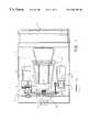
- FIG. 1is an illustration of a cushioning conversion machine
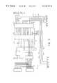
- FIG. 2is a block diagram of a universal controller for a cushioning conversion machine in accordance with the present invention
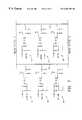
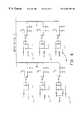
- FIGS. 3 through 8are electrical schematic diagrams of an embodiment of the universal controller
- FIG. 9is a block diagram of a controller for a cushioning conversion machine with enhanced diagnostic capabilities
- FIG. 10is a front view of a length measuring device and other relevant portions of the cushioning conversion machine
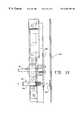
- FIG. 11is a side view of the length measuring device
- FIG. 12is a block diagram of a controller including a code reader for reading information from stock paper and a container probe for determining packaging information from a container to which packaging is to be added;
- FIG. 13is a block diagram of a fault tolerant cushioning producing network
- FIG. 14is an illustration of two cushion producing machines positioned at either end of a conveyor and communicating via a network.
- a cushioning conversion machine 10including a frame 12 upon which the various components of a conversion assembly 14 are mounted and a controller 16 (illustrated schematically) for controlling the machine including the components of the cushioning assembly.
- the frame 12includes a stock supply assembly 18 which holds a roll of stock for conversion by the conversion assembly 14 into a cushioning material.
- the conversion assembly 14preferably includes a feed assembly 19 which includes a forming assembly 20 and a gear assembly 22 powered by a feed motor 24 , a cutting assembly 26 powered by, for example, a cut motor 28 selectively engaged with the cutting assembly by an AC solenoid driven clutch 30 and a post cutting constraining assembly 32 .
- the forming assembly 20causes the lateral edges of the stock material to roll inwardly to form a continuous strip having two lateral pillow-like portions and a central band therebetween.
- the gear assembly 22performs a “pulling” function by drawing the continuous strip through the nip of two cooperating and opposed gears of the gear assembly thereby drawing stock material through the forming assembly 20 for a duration determined by the length of time that the feed motor 24 rotates the opposed gears.
- the gear assembly 22additionally performs a “coining” or “connecting” function as the two opposed gears coin the central band of the continuous strip as it passes therethrough to form a coined strip.
- the cutting assembly 26cuts the strip into sections of a desired length. These cut sections then travel through the post-cutting constraining assembly 32 .
- the controller 16is preferably “universal” or capable of use in a number of differently configured cushioning conversion machines without requiring substantial change to the controller. Accordingly, one configuration of a universal controller 16 can thus be manufactured for a variety of different cushioning conversion machines. The assembly technician then need not adapt the controller 16 to a specific configuration of the cushioning machine, such as when one of the particular cushioning machines is adapted to use an air powered cutting assembly, a direct current powered solenoid cutting assembly, or a motor driven cutting assembly.
- the capability of the universal controller to control differently configured machinesreduces assembly time, reduces assembly cost since the labor cost in specifically configuring a controller often outweighs the cost of assembling unused electrical components in the controller and reduces the possibility of assembly error. Moreover, repair of the machine is facilitated since training of the repair technician is minimized and since an inventory of universal controllers for use in a variety of cushioning machines can be maintained.
- An exemplary universal controller 16is illustrated in FIG. 2 and includes a number of different output ports 36 , 38 , 40 , 42 , 44 and 46 devoted to providing a control signal from a microprocessor 48 to a DC shear solenoid, an AC control solenoid, a cut motor, a feed motor, a counter and a spare port, respectively, in accordance with a number of inputs 50 . While the microprocessor 48 is illustrated and described herein as a single device, it is noted that microprocessor 48 may be embodied as a number of microprocessors or control units of the same type or as different microprocessors adapted for performing certain functions.
- the DC shear solenoidcontrolled by the microprocessor 48 through DC shear solenoid port 36 , powers a cutting blade positioned at the output of a cushioning conversion machine.
- the solenoidactuates a cutting blade to force the blade through the dunnage to make a cut.
- One machine employing a cutting assembly powered by a DC solenoidis marketed by Ranpak Corp. under the name PadPak® and is disclosed in U.S. Pat. No. 4,968,291 which is incorporated herein by this reference.
- the AC control solenoid port 38controls an external AC solenoid which is typically used in conjunction with either an air-powered cutting assembly or a motor powered cutting assembly.
- the cutting assemblyuses the AC solenoid to control the supply of pressurized air to an air cylinder which drives a cutting blade to shear off a section of dunnage fed through the machine.
- a cushioning conversion machine employing an air-powered cutting assemblyis marketed under the name PadPak® by Ranpak Corp. and disclosed in U.S. Pat. No. 4,968,291 which has been incorporated herein above.
- the AC control solenoid port 38may also be used to control an AC solenoid which acts to couple the direct drive cut motor 28 to the cutting assembly 26 via the clutch 30 to drive a cutting blade through a cutting stroke to cut a section of dunnage material fed through the machine.
- an AC solenoidwhich acts to couple the direct drive cut motor 28 to the cutting assembly 26 via the clutch 30 to drive a cutting blade through a cutting stroke to cut a section of dunnage material fed through the machine.
- One such machineis marketed by Ranpak Corp. under the name AutoPad® and is disclosed in U.S. Pat. No. 5,123,889 which is also incorporated herein by this reference.
- the cut motor port 40is used to supply a signal to the cut motor 28 to ensure that the cut motor is running when a cut is desired.
- any of the embodiments of a cushioning conversion machine described abovethere is employed some means for moving the paper material through the machine to create the dunnage material.
- the PadPak® and AutoPad® machines referenced aboveemploy the feed motor 24 which turns the enmeshed gears 22 that grip the paper stock and feed it through the machine where the appropriate conversion of the sheet-like stock to a dunnage product and the cutting of the dunnage product into appropriate lengths takes place.
- the universal controller 16controls the feed motor 24 through the feed motor port 42 .
- the microprocessor 48sends a signal through the feed motor port 42 which causes power to be supplied to the feed motor for as long as the signal is present.
- the signalis disabled causing the feed motor 24 to stop and the supply of paper through the machine to stop.
- the microprocessor 48will determine, based on the position of the mode selection switch 52 and the condition of the input signals 50 , whether to initiate a cut of the dunnage material fed through the machine 10 , as is described more fully below.
- the universal controller 16may also use the counter port 44 to control a counter which keeps track of the machine usage or a spare port 46 which can be used to provide command signals to some other device.
- the universal controller 16includes the output ports 36 through 46 for the control of the feed motor 24 and a variety of cutting assemblies, in most applications less than all of the ports will be used.
- the universal controller 16is used to control a cushioning conversion machine having a DC shear solenoid powered cutting assembly, such as the PadPak® machine mentioned above, the DC shear solenoid port 36 is used while the AC control solenoid port 40 and the cut motor port 16 will not be used.
- the AC control port 38is employed to control the AC control solenoid, and the DC shear solenoid port 36 and the cut motor port 40 may be unused.
- the universal controller 16when the universal controller 16 is used in conjunction with a cushioning conversion machine using the cut motor 28 to actuate the cutting assembly 26 , such as the AutoPad® machine mentioned above, the AC control solenoid port 38 and cut motor port 40 will be used to control and power the cutting assembly 26 while the DC shear solenoid port 36 will be unused.
- the microprocessor 48will more or less simultaneously cause appropriate signals to be sent to each of the respective output ports 36 , 38 , 40 regardless of the actual cutting assembly employed with a machine.
- the microprocessor 48does not need to be informed of this aspect of the configuration of the machine and the cutting assembly 26 connected to a port will thus be the one that responds to a signal sent from the microprocessor without the microprocessor having to distinguish which type of cutting assembly is employed.
- Control of the various devicesis performed by the microprocessor 48 in accordance with certain inputs 50 which are indicative of the operating condition of the cushioning conversion machine 10 and certain events which may have been sensed.
- the inputs 50also include an indication of the operating mode for the cushioning conversion machine selected through the mode selection switch 52 , such as a rotary switch.
- the mode selection switch 52includes a number of settings corresponding to different operating modes, for example, keypad mode, electronic dispensing system mode, automatic cut mode, feed cut foot switch mode, and automatic feed mode.
- the mode setting of the controller 16 as well as a number of error signalsmay be displayed as alphanumeric codes on the display 54 . For example, a display code of ‘1’ may indicate to an operator that the machine 10 is operating in the automatic feed mode, while a display of “A” may indicate that an error has occurred in the buttons used to manually command a cut.
- the keypad modeis for cushioning conversion machines which are equipped with a keypad through which an operator may input the length of each pad which she desires the machine to produce by depressing the appropriate key on the keypad.
- the microprocessor 48provides a signal to the feed motor through the feed motor port 42 to feed material through the machine for the appropriate length of time to provide dunnage of the length which the operator selected through the keypad.
- the keypad buttonsare preferably pre-programmed so that each button corresponds to a particular cut length.
- the microprocessor 48will signal the feed motor 24 and turn the feed motor on for a length of time that equates to 12 inches of dunnage material being fed out, and then the microprocessor will disable the feed motor.
- the microprocessor 48Upon completion of the dunnage material of the selected length being fed through the machine, the microprocessor 48 automatically commands the cutting assembly 26 employed, through the output ports 36 , 38 , and 40 , to perform a cut. The microprocessor 48 then waits for the next key on the keypad to be depressed and repeats the process to produce a length of dunnage corresponding to the key depressed.
- an external electronic dispensing sensoris employed to detect the presence or absence of a dispensed length of dunnage material.
- the information as to the presence or absence of dunnage materialis provided to the microprocessor 48 through one of the inputs 50 . If the sensor detects that there is no dunnage material left at the cutting area of the machine, this information is passed to the microprocessor 48 which will send a signal to the feed motor 24 through the feed motor port 42 to feed out a certain length of material.
- the length of material to be fed through the machine 10is determined by the setting of a thumb wheel, which is described below, as reported to the microprocessor 48 over one of the inputs 50 .
- the electronic dispensing sensorwill report to the microprocessor 48 the presence of the dunnage material at the cutting exit of the machine.
- the microprocessor 48will wait a short period of time to allow the feed motor to stop and will then send a signal over the necessary output ports to command a cut to be performed by the attached cutting assembly 26 .
- the electronic dispensing assemblywill continue to report to the microprocessor 48 the presence of the dunnage material at the exit of the machine until the material is removed.
- the sensorUpon removal of the material, the sensor will report the removal to the microprocessor 48 through the inputs 50 whereupon the microprocessor will send a signal to the feed motor 24 again to feed another length of dunnage material through the machine and once the feed is complete the microprocessor will send a signal over the required output ports to cause the cutting assembly 26 to cut the material. This process will continue as long as the operator continues to remove the cut dunnage from the exit area of the machine.
- the automatic cut mode selection on the selector switch 52causes the microprocessor 48 to perform basically the same process set forth above for the EDS mode with the exception that an operator need not remove a length of dunnage material from the machine in order for the next length to be fed through the machine and cut.
- the microprocessor 48commands the feed motor 24 through the feed motor port 42 to feed material through the machine for a length of time determined by the setting of the thumb wheel.
- the microprocessor 48will disable to signal to the feed motor 24 , will wait a short period of time to allow the feed motor to stop and then will send the appropriate signals to the output ports 36 , 38 , 40 controlling the respective cut assemblies 26 .
- the microprocessor 48will cause predetermined lengths of material to be fed and cut by the machine continuously in this mode unless a predetermined number of lengths has been selected by the operator.
- the control of the machine by the microprocessor 48will be as instructed by an operator actuated foot switch.
- an input indicating the factis sent to the microprocessor 48 through one of the inputs 50 .
- the microprocessor 48will send a signal to the feed motor 24 through the feed motor port 42 to feed material through the machine.
- the signal sent to the feed motor 24 by the microprocessor 48will continue until the operator lets the pressure off of the foot switch at which time the microprocessor will disable the signal to the feed motor, will wait a short period of time to allow the feed motor to stop and then will send a signal to the output ports 36 , 38 , 40 operating the cutting assemblies 26 to cut the material fed through the machine.
- the fifth mode of the mode selection switch 52is the auto feed mode.
- the microprocessor 48signals the feed motor 24 through the feed motor port 42 to feed a length of paper through the machine as determined by the position of the thumb wheel. After the appropriate length of dunnage material has been fed through the machine, the microprocessor will pause until a cut is manually requested. In this mode the operator must then instruct the microprocessor to signal the cut assembly to perform a cut. The operator preferably causes a cut to occur by manually depressing two cut buttons simultaneously.
- both inputsare sent to the microprocessor 48 over the input lines 50 and, provided the buttons have been pushed near simultaneously, the microprocessor will send a signal through the appropriate outputs to the cutting assembly 26 employed on the machine to cut the material. After a cut has been completed, the microprocessor 48 will again send a signal to the feed motor 24 to cause the selected length of material to be fed through the machine and will then wait for the operator to instruct that a cut be made.
- the microprocessor 48may be any one of a number of commercially available general purpose processing chips and preferably one suitable for convenient interface with the output ports 36 through 46 and the inputs 50 through a storage memory 60 , such as a programmable peripheral device that may include ROM, RAM and I/O ports.
- the microprocessor 48is also provided with keypad inputs 62 to which a keypad may be attached when the universal processor 16 is desired to operate in the keypad mode.
- the microprocessorstores the appropriate signal value in a location in the memory 60 accessible to the appropriate output port.
- the microprocessor 48will place the desired signal value in a location in the memory 60 accessible by the line 62 , to send a signal to the cut motor 28 through the cut motor port 40 the signal value will be placed in a location accessible by the line 66 , and to send a signal to the DC shear solenoid through the DC shear solenoid port 36 or to the AC control solenoid through the AC control solenoid port 38 the signal value is placed in a memory location accessible by the line 64 .
- an hour meter 68may also be activated which keeps track of the run time of the cushioning conversion machine.
- the microprocessor 48places a signal value in a location in the memory 60 accessible by these ports or devices.
- the output ports which control a cutting assemblymay be shared by different types of cutting assemblies, for example the AC control solenoid port 38 may control an air powered cutting assembly or the engagement clutch 30 of the cut motor 28 powered cutting assembly 26 , or a single control line may control more than one output port as the control line 64 is shown to control both the DC shear solenoid port 38 and the AC control solenoid port 14 . Further, while only a single cutting assembly 26 is employed by a machine 10 at a time, more than one control line may be used to control a single cutting assembly or to provide other control over the machine.
- both the control lines 64 and 66are used to actuate a cut.
- the control line 66instructs the cut motor 28 through the cut motor port 40 to run while the control line 64 instructs the AC control solenoid through the AC control solenoid port 38 to engage the clutch 30 coupling the cut motor 28 and the cutting blade assembly 26 .
- the control lines 62 and 64are also used cooperatively to ensure that the feed motor 24 is not operating when a cut has been initiated as this may cause the dunnage material to become jammed in the machine.
- a pair of transistors 70 and 72are interconnected with the control lines 62 and 64 so that the feed motor 24 and a cutting assembly 26 cannot both be actuated simultaneously as the presence of a signal on one control line disables the other control line.
- FIG. 6illustrates the thumb wheel circuit 76 discussed above.
- a two-digit thumb wheel 78is coupled to the input bus 50 via the bus interface 80 and control line 82 and allows the operator to select the time during which the microprocessor 48 will command the feed motor 24 via control line 62 and feed motor port 42 to run, and thus the length of dunnage material to be fed through the machine, during the EDS mode, automatic cut mode and the automatic feed mode.
- the selected feed lengthis sent to the microprocessor 24 over the input bus 50 . Shown in FIGS.
- 6 through 8are a number of current sensing circuits which provide additional inputs over the input bus 50 that inform the microprocessor 48 , through the memory 60 , of various operating events of the cushioning conversion machine, e.g. whether a cut has been completed, whether the foot switch is depressed or whether a cut button has been depressed, etc, as well as the selected mode of operation for the universal controller 16 .
- the current sensing circuitsare each of a similar construction but sense unique occurrences.
- An exemplary current sensing circuitgenerally includes a contact 84 which receives current when a particular event specific to that sensing circuit occurs. When such an event occurs, current passes through the contact 84 to a capacitor 86 connected in electrical parallel to a pair of diodes 88 of an opto-coupler 90 arranged in reverse parallel.
- currentis detected across the diodes 88 , indicating that the event which the particular sensing circuit is designed to sense, light from the diodes turns on the phototransistor 92 which causes the transistor to couple a constant voltage source 94 , filtered by a resistor-capacitor filter 96 , to an input 98 to the bus interface 100 .
- the bus interface 100provides the appropriate input to the memory 60 over the input bus 50 as controlled by control line 102 .
- the sensing circuit 104(RELAYS ON) detects whether the cushioning conversion machine has been reset and whether all safety switches are closed indicating that the cover, etc., of the machine is closed. The status of the detection is then sent to the microprocessor 48 via the memory 60 as an input on the input bus 50 .
- the circuit 106senses when an operator has pressed a reverse push button which allows the operator to reverse the rotation direction of the feed motor 24 .
- the purpose of the feed reverse functionis to provide a means for clearing a dunnage material jam. Oftentimes, the jammed dunnage can be cleared by simply reversing the feed motor and pulling the dunnage material away from the cutting assembly where jams most often occur.
- the status of this sensing circuit 106is also reported to the microprocessor 48 over the input bus 50 through the memory 60 .
- the circuit 108senses the status of a cut complete switch. Cutting assemblies using a DC solenoid to drive a cutting blade have an attribute of heating up quickly as power is continually applied to the solenoid. When such a solenoid heats up too much, it loses power and cannot cut as effectively as it can when in a cooler state.
- the cut complete switchdetects whether a cut of the dunnage material has been completed.
- the sensing circuit 108senses the status of the cut complete switch and reports the status to the microprocessor 48 so that the microprocessor can immediately discontinue the supply of power to the DC shear solenoid by sending an appropriate signal to the DC shear solenoid port 36 over the control line 64 .
- the position of the foot switch used when the universal controller 16 has been set to the feed cut foot switch modeis sensed by the sensing circuit 110 (FEED FS).
- the sensing circuit 110senses the position of the foot switch and reports the position to the microprocessor 48 .
- the microprocessor 48will signal the feed motor 24 through the feed motor port 42 and control line 62 to continually feed paper through the machine 10 while the foot switch is depressed.
- the sensing circuitUpon the pressure on the foot switch being released, the sensing circuit will report to the microprocessor 48 that the foot switch has been released and the microprocessor will discontinue the signal to the feed motor causing the feed motor to stop and then the microprocessor will send out a signal to the output ports 36 , 38 and 40 over the control line 64 and 66 prompting the attached cutting assembly 26 to perform a cut.
- the circuit 112senses the status of a blade switch.
- the blade switchdetects whether the knife blade is in its normal at rest position or if the knife blade is at some other point, such as partially through a cut. If the knife blade is at its rest position, it is safe to feed paper through the machine 10 , otherwise if the knife blade was partially through a cut and paper was fed, the paper could feed into the blade and jam the machine.
- the position of the knife blade as sensed by the circuit 112is reported to the microprocessor 48 which will disable signals to the feed motor 24 until the circuit 112 has sensed that the knife blade has returned to its rest position.
- the circuit 114(EDS SEN) senses the presence or absence of dunnage material at the cutting assembly 26 area of the cushioning conversion machine 10 and reports the information to the microprocessor 48 .
- the microprocessor 48will automatically signal the feed motor 24 to feed a length of dunnage material determined by the thumb wheel circuit 76 (FIG. 6) through the machine 10 and signal the attached cutting assembly 26 to cut the material after the appropriate length has been fed whenever the circuit 114 senses that the last length of dunnage material fed has been removed from the exit area.
- the sensing circuits 116correspond to three push buttons located on the cushioning conversion machine 10 which allow for the operator to manually cause the cutting assembly 26 to cut the dunnage material fed through the machine 10 .
- These circuitsare recognized by the microprocessor 48 when the universal controller 16 is in the auto feed mode of operation.
- the microprocessor 48detect an input from one of the circuits 116 , 118 near simultaneously with the detection of an input from the circuit 120 indicating that the COM-CUT button and one of the L-CUT or R-CUT buttons have been pressed near simultaneously before the microprocessor signals the cutting assembly 26 attached to one of the output ports 36 , 38 or 40 to perform a cut.
- the pressing of one of the push buttons by the operatorcauses the corresponding circuit 116 , 118 , 120 to provide an input over the input bus to the memory 60 via the bus interface 122 , input line 124 and control line 126 .
- the sensing circuits 128 , 130 , 132 and 134sense the position of the mode selection switch 52 and indicate whether the mode selector switch is set to the keypad mode (KEYPAD), the EDS mode (EDS SEL), the automatic cut mode (A/M CUT), or the feed cut foot switch mode (F/C COMB), respectively, and report such information to the microprocessor 48 over the input bus 50 to the memory 60 .
- the mode selection switch 52is not set to either the keypad mode, the EDS mode, the automatic cut mode, or the feed cut foot switch mode, the microprocessor 48 will default to operation in accordance with the automatic feed mode described above.
- the sensing circuit 136(COUNTER) senses when a predetermined number of lengths of dunnage material have been generated. When the machine is in the automatic feed mode, the operator sets the counter to the desired number of pads. When this number is reached, a contact closing in the counter is sensed and the circuit 136 informs the microprocessor 48 that the number of dunnage lengths has been reached and the microprocessor disables the automatic feed operation.
- a number of spare sensing circuits 138 (SPARE1), 140 (SPARE2) as seen in FIG. 7,are also provided to enable the microprocessor 48 to perform expanded control functions based on additional inputs.
- the operational status of the machinemay be indicated to the operator through an alphanumeric display 54 (See FIGS. 2 and 5 ).
- the alphanumeric displaymay be any of a variety of commercially available displays capable of interfacing with the microprocessor 48 .
- the microprocessor 48supplies the display 54 with information for display in accordance with information received over the input bus 50 or through other inputs which indicate to the microprocessor 48 the mode of operation of the machine as well as whether any errors have been detected in operation.
- error codes displayed on the display 54flash or blink to enhance the noticeability of the detected error.
- Examples of errors which may be detected by the microprocessor 48are jams in the feed or cutting assemblies 19 , 26 .
- an encoder 144such as an inductive proximity switch, be positioned proximate the coining gears of the gear assembly 22 to sense rotation and rotational speed of the gears and feed motor 24 (See FIG. 1 ), although other forms of detection means could be employed to sense the rotational speed of the various components of the feed assembly 19 .
- the microprocessor 48determines that the rotational speed of the feed motor 24 has dropped below a certain threshold which is indicative of a paper jam in the feed assembly 19 , such as in the gear assembly 22 or forming assembly 20 , the microprocessor stops the feed motor 24 and displays an appropriate error code on the display 54 so the operator can attend to correction of the error.
- the microprocessor 48may similarly monitor the position of the cutting blade as determined by the blade position detecting circuit 112 (See FIG. 7 ). If the blade is not in its rest position after a cut or does not return to its rest position after a period of time from the initiation of a cut cycle, the microprocessor 48 will disable the cutting operation of the machine and send an appropriate error code to the display 54 to inform the operator of the jam in the cutting assembly 26 .
- a controller 216for communication with a remote processor 218 , such as a remote terminal or personal computer, through a pair of modems 220 , 222 , respectively, over a transmission line 224 .
- the remote processor 218 and corresponding modem 222are designated as separate from the controller 216 by the dashed box 226 indicating a remote location, such as a service center.
- the controller 216is generally equivalent to the controller 16 described above relative to FIGS. 1 through 8.
- the microprocessor 48receives a number of inputs 50 corresponding, for example, to events detected by the current sensing circuits shown in FIGS. 6 through 8.
- the information sensed by the current sensing circuitsincludes the operational status of the machine, such as whether the machine is in the key pad mode, the electric dispensing mode, the automatic cut mode, etc., and further includes detection of machine errors, such as jams in the feed or cutting assemblies 19 , 26 , as well as the number of cuts that have been completed by the machine, the number of pads that have been produced by the machine and various other information.
- the controller 216may also be provided with a real-time clock 228 to permit the microprocessor 48 to record a number of timed events, for example the total time the machine is on, the total time the machine is active as opposed to the time devoted to maintenance, the time spent in each of the operational modes, the total time the feed motor or cut motor is running and the total time the feed motor is operating in reverse.
- the real-time clock 228can also be used to time and date stamp occurrences of faults detected by the microprocessor 48 .
- All information received by the microprocessor 48may be stored in a non-volatile memory 230 for later retrieval.
- the information stored in the non-volatile memory 230may be accessed from a remote location 226 through communication between the remote processor 218 and the microprocessor 48 over the modems 220 and 222 .
- the modems 220 and 222may be conventional commercially available modems communicating over a telephone link 224 through conventional communications protocols as would be appreciated by those skilled in the art.
- the information stored in the non-volatile memory 230 of the controller 216may be automatically downloaded to the remote processor 218 at pre-planned timed intervals, for example, at the end of a day, or the end of a week.
- a service person at the remote location 226can instruct the microprocessor 48 through the connection with the remote processor 218 via the modems 220 and 222 to download the information stored in the non-volatile memory 230 to the remote processor 218 as desired.
- the connection between the remote processor 218 and the microprocessor 48allows a service person to view in near real-time the status of all of the machine inputs 50 , corresponding to the sensors and other inputs described above, while the machine is running.
- the information downloaded to the remote processor 218 from the non-volatile memory 230can also be used to schedule maintenance for the machine and to perform billing functions in instances where a customer is charged for use of the machine 10 based on its operating time, on the amount of paper fed through the machine, or on the length or number of pads produced by the machine.
- non-volatile memory 230In instances where a service person is at the site of the cushion conversion machine 10 it is also possible to access the non-volatile memory 230 through the same port provided for communication with the remote processor 218 . In such a case instead of the modem 220 being connected to the microprocessor 48 , a personal computer or other terminal may be connected to the microprocessor 48 for access to the information stored in the non-volatile memory 230 . This allows a service person more access to the informational inputs 50 to the microprocessor 48 during servicing of the machine.
- a paper usage meter 232in communication with the microprocessor 48 . While it is possible for the microprocessor 48 to keep a running total of paper used by the machine in the non-volatile memory 230 by indirectly measuring the time that the feed motor is running as determined by the real time clock 228 and by multiplying that time by the paper speed, provided that the speed of the feed motor is known and constant, in some instances the paper usage may be more accurately determined by use of the paper usage meter 232 .
- Such a metermay include a contact roller which rolls along the paper fed into the machine to directly measure the length of paper used or may be embodied through some other conventional means of measuring length.
- the paper usage, as well as other information stored in the non-volatile memory 230may be made available for display when desirable on the display 54 as well as through the remote processor 218 as is described above.
- the machine 10may be provided with a length measuring device 234 .
- An embodiment of a length measuring deviceis shown in FIGS. 10 and 11 and more fully described in co-owned U.S. patent application Ser. No. 08/155,116, which is incorporated in its entirety by this reference.
- the illustrated length measuring device 234is positioned to monitor the angular movement of the gear assembly 22 .
- the length measuring device 234includes a rotating member 280 which is attached to the gear shaft 281 and a monitor 282 which monitors the angular motion of the member 280 , and thus the gear shaft 281 .
- the rotating member 280is a disk with a series of openings 284 arranged in equal circumferential increments. More preferably, the rotating member 280 is a black, nonreflective, aluminum disk with twelve openings. In this manner, each opening 284 will correspond to a 30° angular movement and, in the preferred embodiment, one inch of pad length.
- the monitor 282comprises a photo-optic transmitter/receiver 286 which transmits and receives light beams and a reflector 288 which reflects the transmitted light beams.
- the transmitter/receiver 286is mounted on the machine frame and is positioned so that, as the rotating member 280 turns, transmitted light beams will travel through the openings 284 .
- the photo-optic transmitter/receiver 286preferably includes electrical circuitry capable of relaying interruptions in the receipt of light beams.
- the reflector 288is mounted on the machine frame and is positioned to receive transmitted light beams which travel through the openings 284 .
- the transmitter/receiver 286relays the occurrence of an interruption to the processor 48 (FIG. 9) in the form of a pulse.
- the processor 48uses this information to control the gear assembly 22 (i.e., to send activation/deactivation signals to the feed motor over the feed motor port 42 ) and thus uses this information to control pad lengths as well as to determine and store in the non-volatile memory 230 the total length of pad produced.
- a controller 216 ′substantially the same as the controller 216 described above and including a paper code reader 300 and a container probe 302 . While the controller 216 ′ is illustrated with only the code reader 300 and container probe 302 and the non-volatile memory 230 , the controller may also include the modem 220 for communication with a remote processor 218 , the real-time clock 228 , the paper usage meter 232 and the length measuring device 234 described with reference to FIG. 9 . The paper code reader 300 and the container probe 302 may also be used separately or together.
- the paper code reader 300reads information encoded on the stock paper 304 as the paper is fed through the machine prior to the paper entering the conversion assembly 20 in order to identify or to verify the stock paper type, source or lot. Such information may aid the service person in diagnosing machine problems, such as problems which have occurred among machines using a particular paper lot, or may be used to determine information regarding the cushioning properties of a pad formed from such paper as may vary between, for example, single or multi-ply paper stock. The latter type of information may be of particular value where the machine 10 automatically determines and produces the amount of pad to adequately cushion a given container.
- the controller 216 ′may in some instances be adapted to produce pads only upon the verification of certain types of stock paper by the paper code reader 300 , such as to as an example prevent damage to the machine 10 from the use of inappropriate stock paper material.
- the paper code reader 300is preferably a conventional bar code reader with the stock paper bearing an appropriate bar code encoded with the desired information.
- the paper code reader 300can also be used to supply paper length information to the processor 48 when the bar codes are printed on the stock paper 302 at known spatial intervals or are encoded with length information.
- the paper code reader 300may also be another type of information retrieval system including, for example, an optical code reader other than a bar code reader or a reader adapted to read or to detect the presence of encoded information using ultraviolet light.
- Information detected from the paper stock 304 by the paper code reader 300is transferred to the processor 48 where it may be acted upon and/or, as desired, stored for latter retrieval from the non-volatile memory 230 .
- the number of rolls or amount of stock paper used from a particular source or the number of rolls or amount of stock paper used of a certain grade, thickness or plyare examples of useful information for storage in the nonvolatile memory 230 .
- the container probe 302may be embodied as a code reader such as a bar code reader which reads information from a container 306 for determining the amount of pad and the lengths of pads to produce to adequately cushion the container.
- a bar codewould be printed on or otherwise affixed to the container 306 or to a packaging invoice supplied with the container and the bar code reader would be positioned to read the bar code as the container is conveyed to or the bar code is placed at a known position relative to the machine 10 .
- the container probe 302Upon reading the information from the bar code, the container probe 302 will transfer the information to the processor 48 which may use the information to instruct the machine 10 to produce the required number and lengths of pads as determined by a look-up table or as directly encoded into the bar code. The operator would then take the pads automatically produced by the machine 10 and place them in the container 306 without further interaction between the operator and the machine.
- the container probe 302may also be in the form of probe which actually measures the void volume of the container.
- a probemay include a mechanical probe such as a plunger, an air cylinder or other low pressure probe which probes the container 306 to determine the volume of padding necessary to fill the container.
- a mechanical probemay probe the container 306 in one or in multiple locations to determine the amount of pad needed.
- the mechanical probemay also be used in conjunction with a bar code reader or used in conjunction with or supplanted with sensors which sense the dimensions or degree of fill of the container 306 including optical and ultrasonic sensors and sensor using other forms of machine vision or pattern recognition.
- a fault tolerant cushioning producing network 400is illustrated schematically in FIG. 13 .
- Such a network 400would typically include a number of cushioning conversion machines 10 each preferably having a controller 402 such as the controllers 16 , 216 and 216 ′ described above for controlling the pad producing and diagnostic functions of the machine.
- the individual machines 10would also be controlled by a supervisory controller 404 which may be a devoted supervisory controller implemented in a personal computer or similar processor or may be resident in a cushioning conversion machine in which case it would control its host machine as well as provide supervisory control functions to its host machine and the other machines in the network 400 .
- the supervisory controller 404may communicate with controllers 402 of each machine 10 in a conventional “master-slave” mode or the controllers may communicate with each other in a conventional “peer-to-peer” mode depending on the level of intercommunication between the machines 10 that is desired and whether it is desired to employ a master supervisory controller.
- the supervisory controller 404can divide up the work load among the different machines according to work schedules and maintenance schedules of the machines and can bypass or reallocate work from a machine which has informed the supervisory controller of a fault condition, such as a paper jam, or that the machine has run out of paper stock.
- the machinesmay also communicate information and fault conditions with each other. While it is preferable that each machine 10 is provided with a separate controller 402 , a machine may be controlled through the supervisory controller 404 without the need of an individual controller for each machine.
- a primary or first machineis active producing pads while the remaining machine or machines are inactive. If the first machine fails, the remaining machine or machines can automatically take over for the first machine.
- Such a networkcould be implemented between two machines 10 a and 10 b at either end of a reversible conveyor system 410 , as shown in FIG. 14 . In this case, in normal operation one machine is active while the other machine is idle. The active machine, say machine 10 a , produces pads of the desired length and deposits the pads onto the conveyor system 410 which carries the pad away from the active machine 10 a and to an operator.
- the machine 10 abecomes inoperable, such as due to a jam or lack of paper for instance, or a switch is desired at a scheduled intervals, the machine 10 a becomes inactive and the machine 10 b takes over the pad producing functions. At this time the direction of the conveyor system 410 would also reverse direction to carry pads produced by the machine 10 b away from that machine and to an operator.
- controllers of the present inventionhave a wide range of applications in controlling the operation of many types or configurations of cushioning conversion machines.
- the versatility and structure of the controllers as well as the provision of spare controller portsalso permits customization of controller functions for different machine applications and control of accessory devices.
Landscapes
- Engineering & Computer Science (AREA)
- Mechanical Engineering (AREA)
- Making Paper Articles (AREA)
- Control Of Conveyors (AREA)
- Buffer Packaging (AREA)
- Control Of Cutting Processes (AREA)
Abstract
Description
Claims (22)
Priority Applications (3)
| Application Number | Priority Date | Filing Date | Title |
|---|---|---|---|
| US08/475,627US6203481B1 (en) | 1994-07-22 | 1995-06-07 | Cushioning conversion machine |
| US09/781,733US7195585B2 (en) | 1994-07-22 | 2001-02-12 | Cushioning conversion machine and method with stock usage monitoring |
| US11/691,089US8272195B2 (en) | 1994-07-22 | 2007-03-26 | Dunnage system with void volume probe |
Applications Claiming Priority (2)
| Application Number | Priority Date | Filing Date | Title |
|---|---|---|---|
| US27914994A | 1994-07-22 | 1994-07-22 | |
| US08/475,627US6203481B1 (en) | 1994-07-22 | 1995-06-07 | Cushioning conversion machine |
Related Parent Applications (1)
| Application Number | Title | Priority Date | Filing Date |
|---|---|---|---|
| US27914994AContinuation-In-Part | 1994-07-22 | 1994-07-22 |
Related Child Applications (1)
| Application Number | Title | Priority Date | Filing Date |
|---|---|---|---|
| US09/781,733ContinuationUS7195585B2 (en) | 1994-07-22 | 2001-02-12 | Cushioning conversion machine and method with stock usage monitoring |
Publications (1)
| Publication Number | Publication Date |
|---|---|
| US6203481B1true US6203481B1 (en) | 2001-03-20 |
Family
ID=23067839
Family Applications (8)
| Application Number | Title | Priority Date | Filing Date |
|---|---|---|---|
| US08/475,626Expired - LifetimeUS5871429A (en) | 1994-07-22 | 1995-06-07 | Cushioning conversion machine including a probe for sensing packaging requirements |
| US08/482,015Expired - Fee RelatedUS5897478A (en) | 1994-07-22 | 1995-06-07 | Cushioning conversion machine and method using encoded stock material |
| US08/475,624Expired - Fee RelatedUS6179762B1 (en) | 1994-07-22 | 1995-06-07 | Cushioning conversion machine |
| US08/475,627Expired - LifetimeUS6203481B1 (en) | 1994-07-22 | 1995-06-07 | Cushioning conversion machine |
| US09/136,987Expired - Fee RelatedUS6055795A (en) | 1994-07-22 | 1998-08-20 | Cushioning conversion machine |
| US09/772,681Expired - LifetimeUS6432032B2 (en) | 1994-07-22 | 2001-01-30 | Cushioning conversion machine |
| US09/781,733Expired - Fee RelatedUS7195585B2 (en) | 1994-07-22 | 2001-02-12 | Cushioning conversion machine and method with stock usage monitoring |
| US11/691,089Expired - Fee RelatedUS8272195B2 (en) | 1994-07-22 | 2007-03-26 | Dunnage system with void volume probe |
Family Applications Before (3)
| Application Number | Title | Priority Date | Filing Date |
|---|---|---|---|
| US08/475,626Expired - LifetimeUS5871429A (en) | 1994-07-22 | 1995-06-07 | Cushioning conversion machine including a probe for sensing packaging requirements |
| US08/482,015Expired - Fee RelatedUS5897478A (en) | 1994-07-22 | 1995-06-07 | Cushioning conversion machine and method using encoded stock material |
| US08/475,624Expired - Fee RelatedUS6179762B1 (en) | 1994-07-22 | 1995-06-07 | Cushioning conversion machine |
Family Applications After (4)
| Application Number | Title | Priority Date | Filing Date |
|---|---|---|---|
| US09/136,987Expired - Fee RelatedUS6055795A (en) | 1994-07-22 | 1998-08-20 | Cushioning conversion machine |
| US09/772,681Expired - LifetimeUS6432032B2 (en) | 1994-07-22 | 2001-01-30 | Cushioning conversion machine |
| US09/781,733Expired - Fee RelatedUS7195585B2 (en) | 1994-07-22 | 2001-02-12 | Cushioning conversion machine and method with stock usage monitoring |
| US11/691,089Expired - Fee RelatedUS8272195B2 (en) | 1994-07-22 | 2007-03-26 | Dunnage system with void volume probe |
Country Status (6)
| Country | Link |
|---|---|
| US (8) | US5871429A (en) |
| EP (3) | EP0776760B2 (en) |
| JP (1) | JP2009226954A (en) |
| KR (1) | KR100376742B1 (en) |
| CN (1) | CN1706718B (en) |
| TW (1) | TW265300B (en) |
Cited By (5)
| Publication number | Priority date | Publication date | Assignee | Title |
|---|---|---|---|---|
| US6626813B1 (en)* | 1997-10-27 | 2003-09-30 | Ranpak Corp. | Cushioning conversion system and method for making a coil of cushioning product |
| US20070117703A1 (en)* | 2005-11-22 | 2007-05-24 | Sealed Air Corporation | Machine and method for converting a web of material into dunnage |
| US20080307756A1 (en)* | 2005-02-18 | 2008-12-18 | Ranpak Corp. | Packaging System with Dunnage Delivery Assembly |
| US20090258775A1 (en)* | 2008-04-11 | 2009-10-15 | Chan Simon C S | Apparatus, systems and methods for producing cushioning material |
| US9884465B2 (en)* | 2011-06-16 | 2018-02-06 | Ranpak Corp. | Dunnage conversion machine and method with downstream feed monitor |
Families Citing this family (46)
| Publication number | Priority date | Publication date | Assignee | Title |
|---|---|---|---|---|
| US6524230B1 (en)* | 1994-07-22 | 2003-02-25 | Ranpak Corp. | Packing material product and method and apparatus for making, monitoring and controlling the same |
| US5871429A (en)* | 1994-07-22 | 1999-02-16 | Ranpak Corp. | Cushioning conversion machine including a probe for sensing packaging requirements |
| FR2743748B1 (en)* | 1996-01-22 | 1998-03-27 | Naturembal Sa | DEVICE FOR MEASURING THE LENGTH OF PADDED BELTS |
| WO1997027136A1 (en)* | 1996-01-22 | 1997-07-31 | Naturembal (Societe Anonyme) | Cushioning pad production machine with a system for measuring the length of the resulting pad |
| FR2746701B1 (en)* | 1996-03-27 | 1998-06-12 | Naturembal Sa | PADDING MATTRESS MANUFACTURING MACHINE WITH INCORRECT ROTATION DETECTION SYSTEM FOR CUTTING MOTOR AND MEASUREMENT OF LENGTH OF MATTRESS PRODUCED. |
| US7335220B2 (en) | 2004-11-05 | 2008-02-26 | Access Closure, Inc. | Apparatus and methods for sealing a vascular puncture |
| FR2786124B1 (en)* | 1998-11-20 | 2000-12-29 | Naturembal Sa | MACHINE FOR THE PRODUCTION OF MATTRESSES OF DIFFERENT LENGTHS |
| DE29820796U1 (en)* | 1998-11-20 | 1999-02-11 | Mathias Bäuerle GmbH, 78112 St Georgen | Upsetting folding machine with adjustable gap widths |
| US6174273B1 (en)* | 1998-12-18 | 2001-01-16 | Ranpak Corp. | Cushioning conversion machine with tension control |
| US7083560B2 (en)* | 1999-09-09 | 2006-08-01 | Ranpak Corp. | Cushioning conversion machine having heavy duty characteristics |
| US20070021286A1 (en)* | 1999-09-03 | 2007-01-25 | Kobben Pierre H G | Cushioning conversion machine having heavy duty characteristics |
| KR20020059388A (en)* | 1999-09-03 | 2002-07-12 | 제임스 제이, 코베트 | Cushioning conversion machine having heavy duty characteristics |
| US6368263B1 (en)* | 1999-09-28 | 2002-04-09 | Agfa Corporation | Punch configuration system and method |
| US6889585B1 (en)* | 2000-01-04 | 2005-05-10 | International Business Machines Corporation | Cutter blade position detection mechanism and method of reporting cutter malfunction |
| SE518917C2 (en)* | 2001-04-06 | 2002-12-03 | Joker System Ab | Device for opening and closing packages |
| US7154018B2 (en) | 2001-12-20 | 2006-12-26 | Kimberly-Clark Worldwide, Inc. | Absorbent article |
| US6891079B2 (en) | 2001-12-20 | 2005-05-10 | Kimberly-Clark Worldwide, Inc. | Wipe |
| US7485110B2 (en) | 2001-12-20 | 2009-02-03 | Kimberly Clark Worldwide, Inc. | Wipe comprising a pathogen selective antimicrobial |
| US6918489B2 (en)* | 2002-04-22 | 2005-07-19 | Ranpak Corp. | Dunnage converter system |
| US6662066B1 (en)* | 2002-04-23 | 2003-12-09 | Taiwan Semiconductor Manufacturing Company | Dynamic adjustment and auto generation of water per hour (WPH) in capacity check system (CCS) by tool performance tracking platform (TP2) |
| MXPA05004523A (en)* | 2002-11-01 | 2005-12-12 | Ranpak Corp | Packaging system with volume fill measurement. |
| DE10346629A1 (en)* | 2003-10-08 | 2005-05-19 | Reinhard Keller | Control for a machine for producing paper upholstery |
| EP2301428B1 (en) | 2003-12-09 | 2016-11-30 | Dexcom, Inc. | Signal processing for continuous analyte sensor |
| US7571589B2 (en)* | 2004-07-15 | 2009-08-11 | Storopack, Inc. | Apparatus for and method of producing and/or separating a string of interconnected packing cushions |
| DE602005027106D1 (en)* | 2004-11-02 | 2011-05-05 | Ranpak Corp | AUTOMATED SYSTEM AND METHOD FOR DISTRIBUTING CRUISE PADDING ELEMENTS |
| EP1893381B1 (en)* | 2005-06-17 | 2012-12-19 | EDW.C. Levy CO | Apparatus and method for shaping slabs of material |
| US7584592B2 (en)* | 2005-08-04 | 2009-09-08 | Ranpak Corp. | Packaging system and method |
| DE602006012996D1 (en) | 2005-08-19 | 2010-04-29 | Ranpak Corp | PACKAGING SYSTEM AND METHOD FOR DETECTING CLOSED CONTAINERS |
| EP2013086B1 (en)* | 2006-04-10 | 2010-06-02 | Ranpak Corp. | Packaging system with volume measurement |
| US8167783B2 (en) | 2006-04-11 | 2012-05-01 | Pack-Tiger Gmbh | Machine for the manufacture of paper padding |
| DE102008039550A1 (en)* | 2008-08-25 | 2010-03-04 | OCé PRINTING SYSTEMS GMBH | Padding element production method for packaging sensitive fixing roller of electrophotographic printer, involves forming padding elements in sections in pad element machine from pad material web |
| DE102010037625A1 (en)* | 2010-09-17 | 2012-03-22 | B & W Verpackungstechnologie Gmbh | Method and device for filling packages with a padding material in bulk form |
| DE102011000561A1 (en) | 2011-02-08 | 2012-08-09 | B & W Solutions GmbH | Method and device for filling packages with a padding material in bulk form |
| US9134724B2 (en)* | 2012-06-12 | 2015-09-15 | Apple Inc. | Method and apparatus for component assembly using continuous selection |
| CN105408101B (en)* | 2013-05-16 | 2017-08-04 | 兰帕克公司 | Dunnage converter jam detecting system and method |
| US9713936B2 (en)* | 2013-12-19 | 2017-07-25 | Pitney Bowes Inc. | System and method for ensuring cutting accuracy in a mailpiece wrapper |
| US20150343807A1 (en) | 2014-05-28 | 2015-12-03 | Toshiba Tec Kabushiki Kaisha | Sheet cutting apparatus and image forming apparatus |
| US20150378352A1 (en)* | 2014-06-27 | 2015-12-31 | Pregis Innovative Packaging Llc | Integrated protective packaging control |
| US10850906B2 (en)* | 2015-03-04 | 2020-12-01 | Storopack, Inc. | Air cushion machine and method |
| EP3319880B1 (en)* | 2015-07-09 | 2023-03-08 | Boothman, Jeff | Automated packing systems and methods |
| BR112019006477B1 (en)* | 2016-10-11 | 2022-11-29 | Ranpak Corp | STEWATCH CUSHION CONVERSION MACHINE FOR CONVERTING A SHEET STOCK MATERIAL INTO A RELATIVELY LOWER DENSITY STEWARE CUSHION PRODUCT, METHOD FOR CONVERTING A SHEET STOCK MATERIAL INTO A RELATIVELY LOWER DENSITY STEWATCH CUSHION PRODUCT, AND CONVERTING MACHINE STOWAGE CUSHION FOR CONVERTING A SHEET STOCK MATERIAL INTO A STOWAGE CUSHION PRODUCT |
| DE102017109842A1 (en)* | 2017-05-08 | 2018-11-08 | Sprick Gmbh Bielefelder Papier- Und Wellpappenwerke & Co. | Apparatus and method for manufacturing a cushion pad from a single or multi-ply continuous paper web |
| DE102017116837A1 (en) | 2017-07-25 | 2019-01-31 | Storopack Hans Reichenecker Gmbh | Device for providing a cushioning agent for packaging purposes |
| DE202019101777U1 (en)* | 2019-03-28 | 2020-07-03 | Altendorf Gmbh | Woodworking machine with a releasable rip fence |
| US11999129B2 (en) | 2021-10-01 | 2024-06-04 | Clayton Cooper | Dunnage production system |
| WO2025096799A1 (en) | 2023-11-03 | 2025-05-08 | Ranpak Corp. | Packing system with foldable flap rotation angle detection |
Citations (64)
| Publication number | Priority date | Publication date | Assignee | Title |
|---|---|---|---|---|
| US1569569A (en) | 1924-11-08 | 1926-01-12 | Pels Henry | Metal-cutting machine |
| US2101170A (en) | 1935-03-25 | 1937-12-07 | Shellmar Products Co | Sheeter |
| US2882802A (en) | 1956-10-29 | 1959-04-21 | Fox Paper Company | Crumpling device |
| US3238852A (en) | 1954-10-05 | 1966-03-08 | Olin Mathieson | Method and apparatus for making filters |
| US3603216A (en) | 1970-02-09 | 1971-09-07 | Arpax Co | Method for producing cushioning dunnage |
| US3613522A (en) | 1969-09-12 | 1971-10-19 | Arpax Co | Method of producing cushioning dunnage |
| US3650877A (en) | 1969-10-06 | 1972-03-21 | Arpax Co | Cushioning dunnage product |
| US3651465A (en) | 1970-05-01 | 1972-03-21 | Parke Davis & Co | Method and apparatus for package inspection and verification |
| US3655500A (en) | 1968-02-07 | 1972-04-11 | Arpax Co | A resilient cushioning dunnage product for use in packaging and packing |
| US3695133A (en) | 1970-07-16 | 1972-10-03 | Euclid Products Co Inc The | Apparatus for cutting strip material in variable lengths |
| US3743140A (en) | 1970-12-21 | 1973-07-03 | Diehl Mateer G Co | Filler apparatus with hopper and rotary feed mechanism for dispensing controlled volumes of materials |
| US3799039A (en) | 1971-12-14 | 1974-03-26 | Ranpak Corp | Cushioning dunnage mechanism and method |
| US3899166A (en) | 1973-12-07 | 1975-08-12 | Super Laundry Mach Co | Laundry folding machine |
| US3949856A (en) | 1972-11-29 | 1976-04-13 | Siemens Aktiengesellschaft | System to detect abnormal paper feed in printers |
| US4026198A (en) | 1975-05-01 | 1977-05-31 | Ranpak Corporation | Cushioning dunnage mechanism, transfer cart therefor, and method |
| US4061326A (en) | 1976-01-26 | 1977-12-06 | Donald Lewis Proudman | Apparatus for folding flatwork |
| US4071911A (en) | 1975-04-22 | 1978-01-31 | Continental Can Co. Inc. | Machine control system with machine serializing and safety circuits |
| DE2741443A1 (en) | 1977-09-14 | 1979-03-29 | Rolf Peddinghaus | Programmable length cutting machine - has measuring system based upon continuous belt with markings that are sensed and counted |
| US4174237A (en) | 1978-07-03 | 1979-11-13 | International Paper Company | Process and apparatus for controlling the speed of web forming equipment |
| US4237776A (en) | 1978-06-02 | 1980-12-09 | Ranpak Corporation | Cushioning dunnage mechanism |
| DE3315520A1 (en) | 1982-04-29 | 1983-11-03 | Mitsubishi Denki K.K., Tokyo | CONTROL FOR A CUTTER |
| US4521847A (en)* | 1982-09-21 | 1985-06-04 | Xerox Corporation | Control system job recovery after a malfunction |
| US4548286A (en) | 1982-12-03 | 1985-10-22 | Kabushiki Kaisha Ishida Koki Seisakusho | Combinatorial weighing method and apparatus with volume and density sensing |
| US4557716A (en) | 1983-07-05 | 1985-12-10 | Ranpak Corp. | Mechanism for producing pad-like cushioning dunnage from sheet material |
| US4619635A (en)* | 1985-11-04 | 1986-10-28 | Ranpak Corp. | Automatic feed circuit for dunnage converter |
| US4650456A (en) | 1985-10-30 | 1987-03-17 | Ranpak Corp. | Mechanism for producing pad-like cushioning dunnage product from sheet material with separate stock roll cart |
| US4699609A (en) | 1986-02-25 | 1987-10-13 | Ranpak Corp. | Electric cutter mechanism for dunnage converter |
| US4705552A (en) | 1985-09-12 | 1987-11-10 | Emhart Industries, Inc. | Glassware forming apparatus with distributed control |
| US4717613A (en) | 1984-05-10 | 1988-01-05 | Ranpak Corporation | Mechanism and method for producing cushioning dunnage |
| US4719449A (en) | 1985-10-01 | 1988-01-12 | Jice Automation | Transport apparatus for transporting part-carrying members to various work stations and for reading data encoded on said part-carrying member |
| US4750896A (en) | 1985-10-28 | 1988-06-14 | Ranpak Corp. | Method and mechanism for producing cushioning dunnage product |
| US4781090A (en) | 1985-12-04 | 1988-11-01 | Windmoller & Holscher | Apparatus for severing sections from a web by transverse severing cuts at locations related to printed marks on the web |
| US4870644A (en)* | 1982-09-21 | 1989-09-26 | Xerox Corporation | Control crash diagnostic strategy and RAM display |
| US4884999A (en) | 1988-01-04 | 1989-12-05 | Ranpak Corp. | Dunnage converter for producing narrow width cushioning pad product, conversion kit thereof, and method |
| DD274188A1 (en) | 1988-07-25 | 1989-12-13 | Bauelemente Faserbaustoffe Veb | DEVICE FOR ABLATING BELT-SOFT MATERIAL |
| US4924506A (en) | 1986-07-22 | 1990-05-08 | Schlumberger Systems & Services, Inc. | Method for directly measuring area and volume using binocular stereo vision |
| US4922687A (en) | 1989-04-24 | 1990-05-08 | Hewlett-Packard Company | Automated packaging loose fill system |
| US4968291A (en) | 1989-05-03 | 1990-11-06 | Ranpak Corp. | Stitching gear assembly having perforating projections thereon, for use in converter adapted to produce pad-like cushioning material, and method |
| US5008842A (en) | 1987-10-19 | 1991-04-16 | Fuji Photo Film Co., Ltd. | Method of sequential monitoring and apparatus for practicing the same |
| US5016182A (en) | 1988-12-29 | 1991-05-14 | Stevens Graphics Corporation | Register control means for web processing apparatus |
| US5023779A (en)* | 1982-09-21 | 1991-06-11 | Xerox Corporation | Distributed processing environment fault isolation |
| US5062052A (en) | 1989-06-20 | 1991-10-29 | Cincinnati Milacron, Inc. | Logic controlled plastic molding machine with programmable operator interface |
| US5088972A (en) | 1989-11-02 | 1992-02-18 | Eco-Pack Industries, Inc. | Folding and crimping apparatus |
| US5088370A (en) | 1989-11-10 | 1992-02-18 | Hitachi Metals Ltd. | Sheet material cutting apparatus |
| US5109347A (en) | 1989-02-07 | 1992-04-28 | The Dow Chemical Company | Computerized volumetric dispensing system |
| US5123889A (en) | 1990-10-05 | 1992-06-23 | Ranpak Corporation | Downsized cushioning dunnage conversion machine and cutting assemblies for use on such a machine |
| US5136222A (en) | 1989-10-09 | 1992-08-04 | Canon Kabushiki Kaisha | Controller for automated apparatus, and method of controlling said apparatus |
| US5180157A (en) | 1991-12-30 | 1993-01-19 | Pitney Bowes Inc. | Self contained transport apparatus with drawer mount |
| US5188581A (en) | 1988-01-04 | 1993-02-23 | Ranpak Corp. | Method for producing a narrow width cushioning paper product |
| US5194720A (en)* | 1991-04-25 | 1993-03-16 | Eastman Kodak Company | Method and apparatus for performing on-line integrated decoding and evaluation of bar code data |
| US5211620A (en) | 1991-11-01 | 1993-05-18 | Ranpak Corp. | Edge-tension controlling device for a cushioning conversion machine |
| US5216593A (en)* | 1991-01-24 | 1993-06-01 | International Business Machines Corporation | Method and apparatus for discrete activity resourse allocation through cardinality constraint generation |
| US5233533A (en)* | 1989-12-19 | 1993-08-03 | Symmetrix, Inc. | Scheduling method and apparatus |
| US5252899A (en) | 1988-03-09 | 1993-10-12 | Fanuc Ltd | Numerical control system |
| US5287194A (en)* | 1992-11-25 | 1994-02-15 | Xerox Corporation | Distributed printing |
| US5303585A (en) | 1991-10-31 | 1994-04-19 | Jtl Medical Corporation | Fluid volume sensor |
| US5322477A (en) | 1990-10-05 | 1994-06-21 | Ranpak Corp. | Downsized cushioning dunnage conversion machine and packaging systems employing the same |
| US5387173A (en) | 1992-12-22 | 1995-02-07 | Ranpak Corp. | Fan-folded stock material for use with a cushioning conversion machine |
| US5398257A (en)* | 1993-01-11 | 1995-03-14 | Groenteman; Frank S. | Copier and monitoring network |
| US5418713A (en) | 1993-08-05 | 1995-05-23 | Allen; Richard | Apparatus and method for an on demand data delivery system for the preview, selection, retrieval and reproduction at a remote location of previously recorded or programmed materials |
| US5442561A (en)* | 1992-05-12 | 1995-08-15 | Nippon Telegraph And Telephone Corporation | Production management system and its application method |
| US5460209A (en) | 1993-12-08 | 1995-10-24 | Massachusetts Institute Of Technology | Automatic dispenser for dry ingredients |
| US5483052A (en) | 1993-12-07 | 1996-01-09 | Smith, Iii; Herbert J. | System for reading, storing and using bar-encoded data from a coded business card or other printed material |
| US5537554A (en)* | 1990-07-06 | 1996-07-16 | Ricoh Company, Ltd. | Method and apparatus for controlling and communicating with business office devices |
Family Cites Families (77)
| Publication number | Priority date | Publication date | Assignee | Title |
|---|---|---|---|---|
| DE274188C (en)* | ||||
| US2924154A (en) | 1956-08-27 | 1960-02-09 | Luber Finer Inc | Method and apparatus for crumpling paper |
| US3074543A (en) | 1958-09-15 | 1963-01-22 | Safe T Pacific Baking Company | Packing material |
| GB1306364A (en)* | 1969-05-15 | 1973-02-07 | ||
| DE2018195C2 (en)* | 1970-04-16 | 1982-07-15 | Hauni-Werke Körber & Co KG, 2050 Hamburg | Method and arrangement for monitoring the application of tobacco processing machines |
| US4071711A (en)* | 1974-08-02 | 1978-01-31 | Farinon Electric Of Canada Ltd. | Telephone subscriber distribution system |
| US4017831A (en)* | 1976-03-15 | 1977-04-12 | The Boeing Company | N/C machine paging, status and report system |
| US4095512A (en)* | 1976-04-08 | 1978-06-20 | Arrow Paper Products Company | Winding of uniform diameter tubes |
| DE2724899C3 (en)* | 1977-06-02 | 1980-09-25 | Christian Majer Kg, Maschinenfabrik, 7400 Tuebingen | Device on a film tube winding machine for controlling a cutting element |
| US4377890A (en)* | 1979-05-21 | 1983-03-29 | Rca Corporation | Method of CRT manufacture using machine readable coded markings |
| US4366372A (en)* | 1979-06-01 | 1982-12-28 | Innovative Design, Inc. | Apparatus and method for counting repetitive marks on a running web |
| US4247289A (en) | 1979-11-02 | 1981-01-27 | Mccabe James E | Paper spring method |
| CA1171942A (en) | 1980-07-21 | 1984-07-31 | Richard Johnstone | Flexible manufacturing system |
| CH648800A5 (en)* | 1980-12-03 | 1985-04-15 | Involvo Ag | COLLECTOR PACKING MACHINE. |
| US4561776A (en)* | 1981-03-25 | 1985-12-31 | Diffracto Ltd. | Electro-optical sensors for tool and robotic inspection |
| IT1169168B (en)* | 1983-02-15 | 1987-05-27 | Gd Spa | FUNCTIONAL CONTROL SYSTEM FOR INPUT TRANSDUCERS OF A CENTRAL CONTROL AND CONTROL UNIT FOR MACHINES AND / OR DEVICES USABLE IN PRODUCTION AND / OR PACKAGING LINES OF PRODUCTS |
| US4585381A (en) | 1983-10-06 | 1986-04-29 | Down River International, Inc. | Void filler |
| US4688708A (en)* | 1984-01-09 | 1987-08-25 | Pitney Bowes Inc. | Bursting machine |
| JPS60184891A (en)* | 1984-03-02 | 1985-09-20 | セイコーインスツルメンツ株式会社 | Cutting system of sheet of paper in automatic drawing machine |
| NL8500720A (en)* | 1984-05-22 | 1985-07-01 | Highland Supply Corp | SYSTEM FOR FORMING ARTICLES. |
| US4773005A (en)* | 1984-09-07 | 1988-09-20 | Tektronix, Inc. | Dynamic address assignment system |
| US4787192A (en)* | 1985-06-24 | 1988-11-29 | Gunther International, Ltd. | Mechanism for folding an envelope around an insert |
| US4741526A (en) | 1986-01-24 | 1988-05-03 | Brandt, Inc. | Adaptive doubles and length measurement techniques and apparatus therefor for use in sheet handling and counting devices |
| US4925121A (en) | 1986-07-01 | 1990-05-15 | Xerox Corporation | Sensing amount of medium and medium roll malfunction in a printer |
| US4943270A (en)* | 1986-09-02 | 1990-07-24 | Cx Corporation | Photographic print cutter |
| US4933711A (en)* | 1987-02-20 | 1990-06-12 | Standard Manufacturing | Apparatus and method for encoding identification data in an automated photofinishing packaging system |
| US5281993A (en)* | 1987-02-20 | 1994-01-25 | Gretag Imaging, Inc. | Photofinishing apparatus and method |
| US4776871A (en)* | 1987-04-23 | 1988-10-11 | Owens-Illinois Glass Container Inc. | Shear blade lockout in an individual section glass machine |
| JPS63300061A (en)* | 1987-05-29 | 1988-12-07 | Matsushita Graphic Commun Syst Inc | Residual amount detector for recording paper |
| DE3868446D1 (en)* | 1987-06-29 | 1992-03-26 | Windmoeller & Hoelscher | METHOD FOR CONTROLLING MACHINES FOR PRODUCING BAGS OR BAGS. |
| US4858101A (en)* | 1987-08-26 | 1989-08-15 | Allen-Bradley Company, Inc. | Programmable controller with parallel processors |
| US4854109A (en)* | 1988-08-22 | 1989-08-08 | Sealed Air | Apparatus and method for forming foam cushions for packaging purposes |
| US5041070A (en)* | 1988-07-29 | 1991-08-20 | Amplas, Inc. | Intermittent web feed apparatus |
| US5068778A (en)* | 1988-11-28 | 1991-11-26 | Reliance Electric Industrial Company | Industrial control system device |
| US4997091A (en)* | 1989-08-17 | 1991-03-05 | Mccrea James S | Package containing biodegradable dunnage material |
| DE3931967A1 (en)* | 1989-09-25 | 1991-04-04 | Windmoeller & Hoelscher | DEVICE FOR CONTROLLING MACHINES FOR PRODUCING BAGS OR BAGS |
| US5084875A (en)* | 1989-12-13 | 1992-01-28 | Joseph Weinberger | System for automatically monitoring copiers from a remote location |
| DE4003192A1 (en) | 1990-02-03 | 1991-08-08 | Focke & Co | METHOD AND DEVICE FOR FEEDING A MATERIAL RAIL TO A VER- OR. PROCESSING MACHINE, ESPECIALLY PACKING MACHINE |
| JPH0729454B2 (en)* | 1990-04-10 | 1995-04-05 | 旭光学工業株式会社 | Printer write position adjustment mechanism |
| DE4018266C2 (en)* | 1990-06-07 | 1997-10-02 | Bat Cigarettenfab Gmbh | Plant for the production and packaging of cigarettes |
| US5065992A (en)* | 1990-06-07 | 1991-11-19 | Roll Systems, Inc. | Method for processing web material |
| US5383130A (en)* | 1990-06-14 | 1995-01-17 | Moore Business Forms, Inc. | Job separator control |
| US5061230A (en)* | 1990-10-26 | 1991-10-29 | Paper Converting Machine Company | Method of controlling bulk in folded webs |
| US5120290A (en)* | 1990-11-26 | 1992-06-09 | Otto Bay | System for positioning cutting and folding computer generated drawing pages |
| US5213867A (en)* | 1990-12-21 | 1993-05-25 | Huston Sr Henry H | Tetrahedral loose-fill packing |
| US5517404A (en)* | 1991-01-23 | 1996-05-14 | Biber; Heinz | Process control in the textile plant |
| IT1245200B (en)* | 1991-03-14 | 1994-09-13 | Sarema S R L | PRINTER GROUP, WITH PERFECT STRUCTURE, FOR CASH REGISTER |
| EP0514340B1 (en)* | 1991-05-16 | 1994-11-02 | Fabriques De Tabac Reunies S.A. | Method and device for preparing packing blanks |
| WO1993001092A1 (en)* | 1991-07-12 | 1993-01-21 | Ishida Scales Mfg. Co., Ltd. | Bag making-wrapping machine |
| US5317654A (en)* | 1991-09-26 | 1994-05-31 | Inscerco Mfg. Inc. | Selective collating and inserting apparatus |
| US5376219A (en)* | 1991-09-26 | 1994-12-27 | Sealed Air Corporation | High speed apparatus for forming foam cushions for packaging purposes |
| FR2682202B1 (en)* | 1991-10-03 | 1994-03-11 | Sextant Avionique | METHOD AND DEVICE FOR REAL-TIME MANAGEMENT OF A SYSTEM COMPRISING AT LEAST ONE PROCESSOR CAPABLE OF MANAGING MULTIPLE FUNCTIONS. |
| US5655009A (en)* | 1992-03-19 | 1997-08-05 | Fujitsu Limited | Modem unit |
| KR940008700B1 (en)* | 1992-04-07 | 1994-09-26 | 주식회사 한국금속 | Pipe cutting device |
| US5322586A (en)* | 1992-05-11 | 1994-06-21 | Reynolds Metals Company | Computer controller heat-sealing machine |
| US5341625A (en)* | 1992-08-27 | 1994-08-30 | Automated Packaging Systems, Inc. | Bagging control apparatus and method |
| US5439730A (en)* | 1992-09-11 | 1995-08-08 | Productive Solutions, Inc. | Flowable loose packing dunnage |
| AU4923893A (en)* | 1992-10-05 | 1994-04-26 | Ranpak Corporation | Paper cushioning product |
| US6029199A (en)* | 1992-10-23 | 2000-02-22 | International Business Machines Corporation | Computing system having a system supervisor and a collection of computing subunits each of which has a subunit supervisor |
| US5504779A (en)* | 1992-12-04 | 1996-04-02 | Reliance Electric Industrial Company | Redundancy modem |
| DE4323293C2 (en)* | 1993-07-12 | 1996-07-25 | Sick Optik Elektronik Erwin | Method and scanning arrangement for identifying a code consisting of successive light and dark fields |
| US5442983A (en) | 1993-09-30 | 1995-08-22 | D'angelo; Joseph J. | All-electric web feeding, cutting and sheet dispensing machine |
| JP3518883B2 (en)* | 1993-10-19 | 2004-04-12 | 株式会社小松製作所 | Die management method in punch press machine |
| WO1995013914A1 (en)* | 1993-11-19 | 1995-05-26 | Ranpak Corp. | A packaging program |
| US5571067A (en)* | 1993-11-19 | 1996-11-05 | Ranpak Corp. | Cushioning conversion machine including a length measuring device |
| US5563809A (en) | 1994-04-06 | 1996-10-08 | Abb Industrial Systems, Inc. | Measurement/control of sheet material using at least one sensor array |
| FR2720155B1 (en)* | 1994-05-19 | 1996-06-28 | Lorraine Laminage | Three-dimensional measurement of the surface of a large object. |
| US5720154A (en)* | 1994-05-27 | 1998-02-24 | Medco Containment Services, Inc. | Enhanced drug dispensing system |
| US6524230B1 (en)* | 1994-07-22 | 2003-02-25 | Ranpak Corp. | Packing material product and method and apparatus for making, monitoring and controlling the same |
| EP0785862B1 (en)* | 1994-07-22 | 2003-06-11 | Ranpak Corp. | Computer controlled cushioning conversion machine |
| US5871429A (en)* | 1994-07-22 | 1999-02-16 | Ranpak Corp. | Cushioning conversion machine including a probe for sensing packaging requirements |
| US5548106A (en)* | 1994-08-30 | 1996-08-20 | Angstrom Technologies, Inc. | Methods and apparatus for authenticating data storage articles |
| US5794416A (en)* | 1996-10-16 | 1998-08-18 | Recot, Inc. | Computer controlled system for loading pallets in a confined cargo area |
| US5829231A (en)* | 1996-11-14 | 1998-11-03 | Ranpak Corporation | Automated cushioning producing and filling system |
| US5910104A (en)* | 1996-12-26 | 1999-06-08 | Cryogen, Inc. | Cryosurgical probe with disposable sheath |
| AU9596798A (en)* | 1997-10-02 | 1999-04-27 | Ranpak Corp. | Packing material product and method and apparatus for making, monitoring and controlling the same |
| US6095803A (en)* | 1999-06-04 | 2000-08-01 | Slater; G. Barry | Thermoplastic adhesive materials conveying system |
- 1995
- 1995-06-07USUS08/475,626patent/US5871429A/ennot_activeExpired - Lifetime
- 1995-06-07USUS08/482,015patent/US5897478A/ennot_activeExpired - Fee Related
- 1995-06-07USUS08/475,624patent/US6179762B1/ennot_activeExpired - Fee Related
- 1995-06-07USUS08/475,627patent/US6203481B1/ennot_activeExpired - Lifetime
- 1995-07-21CNCN2005100786621Apatent/CN1706718B/ennot_activeExpired - Lifetime
- 1995-07-21EPEP97200593Apatent/EP0776760B2/ennot_activeExpired - Lifetime
- 1995-07-21KRKR1019970700426Apatent/KR100376742B1/ennot_activeExpired - Lifetime
- 1995-07-21TWTW084107573Apatent/TW265300B/enactive
- 1995-07-21EPEP06075038Apatent/EP1658964A3/ennot_activeWithdrawn
- 1995-07-21EPEP03075455Apatent/EP1318076B1/ennot_activeExpired - Lifetime
- 1998
- 1998-08-20USUS09/136,987patent/US6055795A/ennot_activeExpired - Fee Related
- 2001
- 2001-01-30USUS09/772,681patent/US6432032B2/ennot_activeExpired - Lifetime
- 2001-02-12USUS09/781,733patent/US7195585B2/ennot_activeExpired - Fee Related
- 2007
- 2007-03-26USUS11/691,089patent/US8272195B2/ennot_activeExpired - Fee Related
- 2009
- 2009-06-08JPJP2009137709Apatent/JP2009226954A/enactivePending
Patent Citations (67)
| Publication number | Priority date | Publication date | Assignee | Title |
|---|---|---|---|---|
| US1569569A (en) | 1924-11-08 | 1926-01-12 | Pels Henry | Metal-cutting machine |
| US2101170A (en) | 1935-03-25 | 1937-12-07 | Shellmar Products Co | Sheeter |
| US3238852A (en) | 1954-10-05 | 1966-03-08 | Olin Mathieson | Method and apparatus for making filters |
| US2882802A (en) | 1956-10-29 | 1959-04-21 | Fox Paper Company | Crumpling device |
| US3655500A (en) | 1968-02-07 | 1972-04-11 | Arpax Co | A resilient cushioning dunnage product for use in packaging and packing |
| US3613522A (en) | 1969-09-12 | 1971-10-19 | Arpax Co | Method of producing cushioning dunnage |
| US3650877A (en) | 1969-10-06 | 1972-03-21 | Arpax Co | Cushioning dunnage product |
| US3603216A (en) | 1970-02-09 | 1971-09-07 | Arpax Co | Method for producing cushioning dunnage |
| US3651465A (en) | 1970-05-01 | 1972-03-21 | Parke Davis & Co | Method and apparatus for package inspection and verification |
| US3695133A (en) | 1970-07-16 | 1972-10-03 | Euclid Products Co Inc The | Apparatus for cutting strip material in variable lengths |
| US3743140A (en) | 1970-12-21 | 1973-07-03 | Diehl Mateer G Co | Filler apparatus with hopper and rotary feed mechanism for dispensing controlled volumes of materials |
| US3799039A (en) | 1971-12-14 | 1974-03-26 | Ranpak Corp | Cushioning dunnage mechanism and method |
| US3949856A (en) | 1972-11-29 | 1976-04-13 | Siemens Aktiengesellschaft | System to detect abnormal paper feed in printers |
| US3899166A (en) | 1973-12-07 | 1975-08-12 | Super Laundry Mach Co | Laundry folding machine |
| US4071911A (en) | 1975-04-22 | 1978-01-31 | Continental Can Co. Inc. | Machine control system with machine serializing and safety circuits |
| US4026198A (en) | 1975-05-01 | 1977-05-31 | Ranpak Corporation | Cushioning dunnage mechanism, transfer cart therefor, and method |
| US4085662A (en) | 1975-05-01 | 1978-04-25 | Ranpak Corporation | Method of making and using cushioning dunnage material |
| US4109040A (en) | 1975-05-01 | 1978-08-22 | Ranpak Corporation | Cushioning dunnage product produced from cushioning dunnage mechanism |
| US4061326A (en) | 1976-01-26 | 1977-12-06 | Donald Lewis Proudman | Apparatus for folding flatwork |
| DE2741443A1 (en) | 1977-09-14 | 1979-03-29 | Rolf Peddinghaus | Programmable length cutting machine - has measuring system based upon continuous belt with markings that are sensed and counted |
| US4237776A (en) | 1978-06-02 | 1980-12-09 | Ranpak Corporation | Cushioning dunnage mechanism |
| US4174237A (en) | 1978-07-03 | 1979-11-13 | International Paper Company | Process and apparatus for controlling the speed of web forming equipment |
| DE3315520A1 (en) | 1982-04-29 | 1983-11-03 | Mitsubishi Denki K.K., Tokyo | CONTROL FOR A CUTTER |
| US4521847A (en)* | 1982-09-21 | 1985-06-04 | Xerox Corporation | Control system job recovery after a malfunction |
| US5023779A (en)* | 1982-09-21 | 1991-06-11 | Xerox Corporation | Distributed processing environment fault isolation |
| US4870644A (en)* | 1982-09-21 | 1989-09-26 | Xerox Corporation | Control crash diagnostic strategy and RAM display |
| US4548286A (en) | 1982-12-03 | 1985-10-22 | Kabushiki Kaisha Ishida Koki Seisakusho | Combinatorial weighing method and apparatus with volume and density sensing |
| US4557716A (en) | 1983-07-05 | 1985-12-10 | Ranpak Corp. | Mechanism for producing pad-like cushioning dunnage from sheet material |
| US4717613A (en) | 1984-05-10 | 1988-01-05 | Ranpak Corporation | Mechanism and method for producing cushioning dunnage |
| US4705552A (en) | 1985-09-12 | 1987-11-10 | Emhart Industries, Inc. | Glassware forming apparatus with distributed control |
| US4719449A (en) | 1985-10-01 | 1988-01-12 | Jice Automation | Transport apparatus for transporting part-carrying members to various work stations and for reading data encoded on said part-carrying member |
| US4750896A (en) | 1985-10-28 | 1988-06-14 | Ranpak Corp. | Method and mechanism for producing cushioning dunnage product |
| US4650456A (en) | 1985-10-30 | 1987-03-17 | Ranpak Corp. | Mechanism for producing pad-like cushioning dunnage product from sheet material with separate stock roll cart |
| US4619635A (en)* | 1985-11-04 | 1986-10-28 | Ranpak Corp. | Automatic feed circuit for dunnage converter |
| US4781090A (en) | 1985-12-04 | 1988-11-01 | Windmoller & Holscher | Apparatus for severing sections from a web by transverse severing cuts at locations related to printed marks on the web |
| US4699609A (en) | 1986-02-25 | 1987-10-13 | Ranpak Corp. | Electric cutter mechanism for dunnage converter |
| US4924506A (en) | 1986-07-22 | 1990-05-08 | Schlumberger Systems & Services, Inc. | Method for directly measuring area and volume using binocular stereo vision |
| US5008842A (en) | 1987-10-19 | 1991-04-16 | Fuji Photo Film Co., Ltd. | Method of sequential monitoring and apparatus for practicing the same |
| US4884999A (en) | 1988-01-04 | 1989-12-05 | Ranpak Corp. | Dunnage converter for producing narrow width cushioning pad product, conversion kit thereof, and method |
| US5188581A (en) | 1988-01-04 | 1993-02-23 | Ranpak Corp. | Method for producing a narrow width cushioning paper product |
| US5252899A (en) | 1988-03-09 | 1993-10-12 | Fanuc Ltd | Numerical control system |
| DD274188A1 (en) | 1988-07-25 | 1989-12-13 | Bauelemente Faserbaustoffe Veb | DEVICE FOR ABLATING BELT-SOFT MATERIAL |
| US5016182A (en) | 1988-12-29 | 1991-05-14 | Stevens Graphics Corporation | Register control means for web processing apparatus |
| US5109347A (en) | 1989-02-07 | 1992-04-28 | The Dow Chemical Company | Computerized volumetric dispensing system |
| US4922687A (en) | 1989-04-24 | 1990-05-08 | Hewlett-Packard Company | Automated packaging loose fill system |
| US4968291A (en) | 1989-05-03 | 1990-11-06 | Ranpak Corp. | Stitching gear assembly having perforating projections thereon, for use in converter adapted to produce pad-like cushioning material, and method |
| US5062052A (en) | 1989-06-20 | 1991-10-29 | Cincinnati Milacron, Inc. | Logic controlled plastic molding machine with programmable operator interface |
| US5062052B1 (en) | 1989-06-20 | 1997-11-18 | Cincinnati Milacron Inc | Logic controlled plastic molding machine with programmable operator interface |
| US5136222A (en) | 1989-10-09 | 1992-08-04 | Canon Kabushiki Kaisha | Controller for automated apparatus, and method of controlling said apparatus |
| US5088972A (en) | 1989-11-02 | 1992-02-18 | Eco-Pack Industries, Inc. | Folding and crimping apparatus |
| US5088370A (en) | 1989-11-10 | 1992-02-18 | Hitachi Metals Ltd. | Sheet material cutting apparatus |
| US5233533A (en)* | 1989-12-19 | 1993-08-03 | Symmetrix, Inc. | Scheduling method and apparatus |
| US5537554A (en)* | 1990-07-06 | 1996-07-16 | Ricoh Company, Ltd. | Method and apparatus for controlling and communicating with business office devices |
| US5322477A (en) | 1990-10-05 | 1994-06-21 | Ranpak Corp. | Downsized cushioning dunnage conversion machine and packaging systems employing the same |
| US5123889A (en) | 1990-10-05 | 1992-06-23 | Ranpak Corporation | Downsized cushioning dunnage conversion machine and cutting assemblies for use on such a machine |
| US5216593A (en)* | 1991-01-24 | 1993-06-01 | International Business Machines Corporation | Method and apparatus for discrete activity resourse allocation through cardinality constraint generation |
| US5194720A (en)* | 1991-04-25 | 1993-03-16 | Eastman Kodak Company | Method and apparatus for performing on-line integrated decoding and evaluation of bar code data |
| US5303585A (en) | 1991-10-31 | 1994-04-19 | Jtl Medical Corporation | Fluid volume sensor |
| US5211620A (en) | 1991-11-01 | 1993-05-18 | Ranpak Corp. | Edge-tension controlling device for a cushioning conversion machine |
| US5180157A (en) | 1991-12-30 | 1993-01-19 | Pitney Bowes Inc. | Self contained transport apparatus with drawer mount |
| US5442561A (en)* | 1992-05-12 | 1995-08-15 | Nippon Telegraph And Telephone Corporation | Production management system and its application method |
| US5287194A (en)* | 1992-11-25 | 1994-02-15 | Xerox Corporation | Distributed printing |
| US5387173A (en) | 1992-12-22 | 1995-02-07 | Ranpak Corp. | Fan-folded stock material for use with a cushioning conversion machine |
| US5398257A (en)* | 1993-01-11 | 1995-03-14 | Groenteman; Frank S. | Copier and monitoring network |
| US5418713A (en) | 1993-08-05 | 1995-05-23 | Allen; Richard | Apparatus and method for an on demand data delivery system for the preview, selection, retrieval and reproduction at a remote location of previously recorded or programmed materials |
| US5483052A (en) | 1993-12-07 | 1996-01-09 | Smith, Iii; Herbert J. | System for reading, storing and using bar-encoded data from a coded business card or other printed material |
| US5460209A (en) | 1993-12-08 | 1995-10-24 | Massachusetts Institute Of Technology | Automatic dispenser for dry ingredients |
Cited By (7)
| Publication number | Priority date | Publication date | Assignee | Title |
|---|---|---|---|---|
| US6626813B1 (en)* | 1997-10-27 | 2003-09-30 | Ranpak Corp. | Cushioning conversion system and method for making a coil of cushioning product |
| US20080307756A1 (en)* | 2005-02-18 | 2008-12-18 | Ranpak Corp. | Packaging System with Dunnage Delivery Assembly |
| US7665275B2 (en) | 2005-02-18 | 2010-02-23 | Ranpak Corp. | Packaging system with dunnage delivery assembly |
| US20070117703A1 (en)* | 2005-11-22 | 2007-05-24 | Sealed Air Corporation | Machine and method for converting a web of material into dunnage |
| US20090258775A1 (en)* | 2008-04-11 | 2009-10-15 | Chan Simon C S | Apparatus, systems and methods for producing cushioning material |
| US8550971B2 (en) | 2008-04-11 | 2013-10-08 | Nuevopak Technology Company Limited | Systems for producing cushioning material |
| US9884465B2 (en)* | 2011-06-16 | 2018-02-06 | Ranpak Corp. | Dunnage conversion machine and method with downstream feed monitor |
Also Published As
| Publication number | Publication date |
|---|---|
| EP1318076A3 (en) | 2003-10-08 |
| US6432032B2 (en) | 2002-08-13 |
| US7195585B2 (en) | 2007-03-27 |
| US6055795A (en) | 2000-05-02 |
| CN1706718B (en) | 2010-04-14 |
| EP1658964A2 (en) | 2006-05-24 |
| JP2009226954A (en) | 2009-10-08 |
| US20010014642A1 (en) | 2001-08-16 |
| EP1318076A2 (en) | 2003-06-11 |
| EP1318076B1 (en) | 2006-03-08 |
| US5897478A (en) | 1999-04-27 |
| US5871429A (en) | 1999-02-16 |
| EP0776760A1 (en) | 1997-06-04 |
| EP1658964A3 (en) | 2008-02-27 |
| US20070283670A1 (en) | 2007-12-13 |
| US8272195B2 (en) | 2012-09-25 |
| EP0776760B2 (en) | 2006-12-27 |
| US6179762B1 (en) | 2001-01-30 |
| TW265300B (en) | 1995-12-11 |
| KR100376742B1 (en) | 2003-06-09 |
| CN1706718A (en) | 2005-12-14 |
| US20010019990A1 (en) | 2001-09-06 |
| EP0776760B1 (en) | 1999-05-06 |
Similar Documents
| Publication | Publication Date | Title |
|---|---|---|
| US6203481B1 (en) | Cushioning conversion machine | |
| US5864484A (en) | Cushioning conversion machine | |
| EP1019245B1 (en) | System and method for monitoring packaging material conversion machines | |
| US7260922B2 (en) | Packing material product and method and apparatus for making, monitoring and controlling the same | |
| US5571067A (en) | Cushioning conversion machine including a length measuring device | |
| CA2614651C (en) | Computer controlled cushioning conversion machine |
Legal Events
| Date | Code | Title | Description |
|---|---|---|---|
| AS | Assignment | Owner name:RANPAK CORP., OHIO Free format text:ASSIGNMENT OF ASSIGNORS INTEREST;ASSIGNORS:HARDING, JOSEPH J.;RATZEL, RICHARD O.;REEL/FRAME:007617/0485 Effective date:19950606 | |
| AS | Assignment | Owner name:KEYBANK NATIONAL ASSOCIATION, OHIO Free format text:SECURITY AGREEMENT;ASSIGNOR:RANPAK CORP.;REEL/FRAME:008328/0726 Effective date:19960820 | |
| STCF | Information on status: patent grant | Free format text:PATENTED CASE | |
| AS | Assignment | Owner name:GENERAL ELECTRIC CAPITAL CORPORATION, AS AGENT, CO Free format text:SECURITY AGREEMENT;ASSIGNOR:RANPAK CORP.;REEL/FRAME:012418/0493 Effective date:20011228 | |
| CC | Certificate of correction | ||
| AS | Assignment | Owner name:GENERAL ELECTRIC CAPITAL CORPORATION, CONNECTICUT Free format text:SECURITY AGREEMENT;ASSIGNOR:RANPAK CORP.;REEL/FRAME:014709/0832 Effective date:20040526 | |
| FPAY | Fee payment | Year of fee payment:4 | |
| AS | Assignment | Owner name:SPECIAL SITUATIONS INVESTING GROUP, INC., NEW YORK Free format text:SECURITY AGREEMENT;ASSIGNOR:RANPAK CORP.;REEL/FRAME:015676/0883 Effective date:20040727 | |
| FEPP | Fee payment procedure | Free format text:PAT HOLDER NO LONGER CLAIMS SMALL ENTITY STATUS, ENTITY STATUS SET TO UNDISCOUNTED (ORIGINAL EVENT CODE: STOL); ENTITY STATUS OF PATENT OWNER: LARGE ENTITY | |
| AS | Assignment | Owner name:GENERAL ELECTRIC CAPITAL CORPORATION, AS AGENT, CO Free format text:SECURITY INTEREST;ASSIGNOR:RANPAK CORP;REEL/FRAME:015861/0341 Effective date:20050317 | |
| SULP | Surcharge for late payment | ||
| AS | Assignment | Owner name:RANPAK CORP, OHIO Free format text:RELEASE OF SECURITY INTEREST;ASSIGNOR:SPECIAL SITUATIONS INVESTING GROUP, INC.;REEL/FRAME:016784/0231 Effective date:20041104 | |
| AS | Assignment | Owner name:GENERAL ELECTRIC CAPITAL CORPROATION, CONNECTICUT Free format text:SECURITY AGREEMENT;ASSIGNOR:RANPAK CORP.;REEL/FRAME:016945/0612 Effective date:20051214 | |
| AS | Assignment | Owner name:RANPAK CORP., OHIO Free format text:RELEASE OF SECURITY INTEREST;ASSIGNOR:GENERAL ELECTRIC CAPITAL CORPORATION;REEL/FRAME:016967/0696 Effective date:20051214 Owner name:RANPAK CORP., OHIO Free format text:RELEASE OF SECURITY INTEREST;ASSIGNOR:GENERAL ELECTRIC CAPITAL CORPORATION;REEL/FRAME:016976/0302 Effective date:20051214 Owner name:RANPAK CORP., OHIO Free format text:RELEASE OF SECURITY INTEREST;ASSIGNOR:GENERAL ELECTRIC CAPITAL CORPORATION;REEL/FRAME:016976/0285 Effective date:20051214 | |
| AS | Assignment | Owner name:RANPAK CORP., OHIO Free format text:RELEASE OF SECURITY INTEREST INTELLECTUAL PROPERTY COLLATERAL;ASSIGNOR:GENERAL ELECTRIC CAPITAL CORPORATION, AS AGENT;REEL/FRAME:020362/0864 Effective date:20071227 Owner name:RANPAK CORP.,OHIO Free format text:RELEASE OF SECURITY INTEREST INTELLECTUAL PROPERTY COLLATERAL;ASSIGNOR:GENERAL ELECTRIC CAPITAL CORPORATION, AS AGENT;REEL/FRAME:020362/0864 Effective date:20071227 | |
| AS | Assignment | Owner name:AMERICAN CAPITAL FINANCIAL SERVICES, INC., AS AGEN Free format text:FIRST LIEN PATENT SECURITY AGREEMENT;ASSIGNOR:RANPAK CORP.;REEL/FRAME:020690/0276 Effective date:20071227 | |
| AS | Assignment | Owner name:AMERICAN CAPITAL FINANCIAL SERVICES, INC., AS AGEN Free format text:SECOND LIEN PATENT SECURITY AGREEMENT;ASSIGNOR:RANPAK CORP.;REEL/FRAME:020497/0927 Effective date:20071227 | |
| FPAY | Fee payment | Year of fee payment:8 | |
| AS | Assignment | Owner name:RANPAK CORP., OHIO Free format text:RELEASE BY SECURED PARTY;ASSIGNOR:AMERICAN CAPITAL, LTD. (SUCCESSOR TO AMERICAN CAPITAL FINANCIAL SERVICES, INC.);REEL/FRAME:026159/0237 Effective date:20110420 Owner name:RANPAK CORP., OHIO Free format text:RELEASE BY SECURED PARTY;ASSIGNOR:AMERICAN CAPITAL, LTD. (SUCCESSOR TO AMERICAN CAPITAL FINANCIAL SERVICES, INC.);REEL/FRAME:026159/0279 Effective date:20110420 | |
| AS | Assignment | Owner name:GOLDMAN SACHS LENDING PARTNERS LLC, NEW YORK Free format text:SECURITY AGREEMENT;ASSIGNOR:RANPAK CORP.;REEL/FRAME:026161/0305 Effective date:20110420 | |
| AS | Assignment | Owner name:BANK OF AMERICA, N.A., AS COLLATERAL AGENT, CALIFO Free format text:PATENT SECURITY AGREEMENT;ASSIGNOR:RANPAK CORP.;REEL/FRAME:026276/0638 Effective date:20110420 | |
| FPAY | Fee payment | Year of fee payment:12 | |
| AS | Assignment | Owner name:GOLDMAN SACHS BANK USA, NEW JERSEY Free format text:SECURITY AGREEMENT;ASSIGNOR:RANPAK CORP.;REEL/FRAME:030271/0112 Effective date:20130423 Owner name:RANPAK CORP., OHIO Free format text:RELEASE BY SECURED PARTY;ASSIGNOR:BANK OF AMERICA, N.A., AS COLLATERAL AGENT;REEL/FRAME:030271/0097 Effective date:20130423 Owner name:RANPAK CORP., OHIO Free format text:RELEASE BY SECURED PARTY;ASSIGNOR:GOLDMAN SACHS LENDING PARTNERS LLC;REEL/FRAME:030271/0031 Effective date:20130423 | |
| AS | Assignment | Owner name:GOLDMAN SACHS BANK USA, AS COLLATERAL AGENT, NEW J Free format text:SECURITY AGREEMENT;ASSIGNOR:RANPAK CORP.;REEL/FRAME:030276/0413 Effective date:20130423 | |
| AS | Assignment | Owner name:RANPAK CORP., OHIO Free format text:TERMINATION OF SECURITY INTEREST IN PATENTS (FIRST LIEN);ASSIGNOR:GOLDMAN SACHS BANK USA;REEL/FRAME:049218/0049 Effective date:20141001 Owner name:RANPAK CORP., OHIO Free format text:TERMINATION OF SECURITY INTEREST IN PATENTS (SECOND LIEN);ASSIGNOR:GOLDMAN SACHS BANK USA;REEL/FRAME:049217/0429 Effective date:20141001 |