US6203266B1 - Power safety barrier for wheelchair lift - Google Patents
Power safety barrier for wheelchair liftDownload PDFInfo
- Publication number
- US6203266B1 US6203266B1US08/958,651US95865197AUS6203266B1US 6203266 B1US6203266 B1US 6203266B1US 95865197 AUS95865197 AUS 95865197AUS 6203266 B1US6203266 B1US 6203266B1
- Authority
- US
- United States
- Prior art keywords
- platform
- roll stop
- stop plate
- safety barrier
- closed position
- Prior art date
- Legal status (The legal status is an assumption and is not a legal conclusion. Google has not performed a legal analysis and makes no representation as to the accuracy of the status listed.)
- Expired - Lifetime
Links
- 230000004888barrier functionEffects0.000titleclaimsabstractdescription74
- 230000007246mechanismEffects0.000claimsabstractdescription30
- 230000003213activating effectEffects0.000claims1
- 238000005096rolling processMethods0.000abstractdescription7
- 230000000903blocking effectEffects0.000abstractdescription5
- 230000007704transitionEffects0.000abstractdescription4
- 208000027418Wounds and injuryDiseases0.000description2
- 230000006378damageEffects0.000description2
- 208000014674injuryDiseases0.000description2
- 230000004048modificationEffects0.000description2
- 238000012986modificationMethods0.000description2
- 210000003813thumbAnatomy0.000description2
- 241000271569RheaSpecies0.000description1
- 230000001154acute effectEffects0.000description1
- JTJMJGYZQZDUJJ-UHFFFAOYSA-NphencyclidineChemical compoundC1CCCCN1C1(C=2C=CC=CC=2)CCCCC1JTJMJGYZQZDUJJ-UHFFFAOYSA-N0.000description1
Images


Classifications
- B—PERFORMING OPERATIONS; TRANSPORTING
- B60—VEHICLES IN GENERAL
- B60P—VEHICLES ADAPTED FOR LOAD TRANSPORTATION OR TO TRANSPORT, TO CARRY, OR TO COMPRISE SPECIAL LOADS OR OBJECTS
- B60P1/00—Vehicles predominantly for transporting loads and modified to facilitate loading, consolidating the load, or unloading
- B60P1/44—Vehicles predominantly for transporting loads and modified to facilitate loading, consolidating the load, or unloading having a loading platform thereon raising the load to the level of the load-transporting element
- B60P1/4457—Means for immobilising the load or preventing it from rolling off during lifting; Man-rails
- A—HUMAN NECESSITIES
- A61—MEDICAL OR VETERINARY SCIENCE; HYGIENE
- A61G—TRANSPORT, PERSONAL CONVEYANCES, OR ACCOMMODATION SPECIALLY ADAPTED FOR PATIENTS OR DISABLED PERSONS; OPERATING TABLES OR CHAIRS; CHAIRS FOR DENTISTRY; FUNERAL DEVICES
- A61G3/00—Ambulance aspects of vehicles; Vehicles with special provisions for transporting patients or disabled persons, or their personal conveyances, e.g. for facilitating access of, or for loading, wheelchairs
- A61G3/02—Loading or unloading personal conveyances; Facilitating access of patients or disabled persons to, or exit from, vehicles
- A61G3/06—Transfer using ramps, lifts or the like
- A61G3/062—Transfer using ramps, lifts or the like using lifts connected to the vehicle
- B—PERFORMING OPERATIONS; TRANSPORTING
- B60—VEHICLES IN GENERAL
- B60P—VEHICLES ADAPTED FOR LOAD TRANSPORTATION OR TO TRANSPORT, TO CARRY, OR TO COMPRISE SPECIAL LOADS OR OBJECTS
- B60P1/00—Vehicles predominantly for transporting loads and modified to facilitate loading, consolidating the load, or unloading
- B60P1/44—Vehicles predominantly for transporting loads and modified to facilitate loading, consolidating the load, or unloading having a loading platform thereon raising the load to the level of the load-transporting element
- B60P1/4471—General means for controlling movements of the loading platform, e.g. hydraulic systems
- B60P1/4478—Safety stops, switches
- Y—GENERAL TAGGING OF NEW TECHNOLOGICAL DEVELOPMENTS; GENERAL TAGGING OF CROSS-SECTIONAL TECHNOLOGIES SPANNING OVER SEVERAL SECTIONS OF THE IPC; TECHNICAL SUBJECTS COVERED BY FORMER USPC CROSS-REFERENCE ART COLLECTIONS [XRACs] AND DIGESTS
- Y10—TECHNICAL SUBJECTS COVERED BY FORMER USPC
- Y10S—TECHNICAL SUBJECTS COVERED BY FORMER USPC CROSS-REFERENCE ART COLLECTIONS [XRACs] AND DIGESTS
- Y10S414/00—Material or article handling
- Y10S414/13—Handlers utilizing parallel links
- Y—GENERAL TAGGING OF NEW TECHNOLOGICAL DEVELOPMENTS; GENERAL TAGGING OF CROSS-SECTIONAL TECHNOLOGIES SPANNING OVER SEVERAL SECTIONS OF THE IPC; TECHNICAL SUBJECTS COVERED BY FORMER USPC CROSS-REFERENCE ART COLLECTIONS [XRACs] AND DIGESTS
- Y10—TECHNICAL SUBJECTS COVERED BY FORMER USPC
- Y10S—TECHNICAL SUBJECTS COVERED BY FORMER USPC CROSS-REFERENCE ART COLLECTIONS [XRACs] AND DIGESTS
- Y10S414/00—Material or article handling
- Y10S414/134—Handicapped person handling
Definitions
- the present inventiongenerally relates to the field of vehicular wheelchair lifts for persons who are physically challenged or otherwise have limited mobility. More particularly, the present invention relates to the field of vehicular wheelchair lifts with an automatic safety barrier for preventing a wheelchair from inadvertently rolling off a platform of the wheelchair lift in the boarding and exiting of a vehicle.
- Vehicular wheelchair liftsare widely utilized to assist persons in wheelchairs to enter and exit vehicles. These lifts typically have a platform for transporting an occupied wheelchair, where the platform can be raised and lowered between a loading position at the ground level outside a vehicle and an entry position at the floor level inside the vehicle, and a safety barrier connected to an outer end of the platform for preventing a wheelchair from inadvertently rolling off the platform during use of the wheelchair lift.
- U.S. Pat. No. 5,556,250 issued to Fretwell et al. on Sep. 17, 1996discloses a wheelchair lift with a power roll stop actuated by a separate motor drive mechanism. If power or the motor becomes inoperable by any reason, disassembly some linkage parts in the motor drive mechanism is a must in order to, manually open and close the roll stop.
- U.S. Pat. No. 4,124,130 issued to Rohrs et al. on Nov. 7, 1978discloses a wheelchair lift with a safety barrier.
- the safety barrieris not power controlled.
- U.S. Pat. No. 5,040,936 issued to Rhea on Aug. 20, 1991discloses a wheelchair lift with a foldable safety barrier.
- the safety barrieris not power controlled.
- U.S. Pat. No. 4,556,128 issued to Thorley et al. on Dec. 3, 1985discloses a wheelchair lift with a power safety barrier.
- the safety barrieris actuated by a hydraulic cylinder. If the hydraulic power or any element becomes inoperable, the safety barrier cannot be opened and closed manually.
- U.S. Pat. No. 5,439,342 issued to Hall et al. on Aug. 8, 1995discloses a platform wheelchair lift with a safety barrier actuation mechanism.
- the actuation mechanismis driven by a hydraulic cyliner.
- the barriercannot be opened and closed manually in the event of a power failure.
- U.S. Pat. No. 4,442,921 issued to Sherman on Apr. 17, 1984discloses a wheelchair platform lift with a safety barrier.
- the barrieris actuated by a barrier pivotal latch mechanism without power control.
- U.S. Pat. No. 5,401,135 issued to Stoen et al. on Mar. 28, 1995discloses a wheelchair lift with a safety barrier.
- the barrieropens and closes by a barrier pivotal latch mechanism without power control.
- a wheelchair liftwith a power controlled safety barrier for facilitating the entrance and exit of persons who are physically challenged or otherwise have limited mobility into or from a vehicle which significantly improves the safety of the wheelchair lift. It is also desirable to provide a wheelchair lift with a power controlled safety barrier which eliminates risks attributable to a wheelchair inadvertently rolling off a platform of the wheelchair lift during use.
- the present inventionis a vehicular wheelchair lift with a power controlled safety barrier for physically blocking a wheelchair from inadvertently rolling off a platform of the wheelchair lift during use.
- the power safety barrierutilizes a linkage mechanism for lowering or raising a roll stop.
- the linkage mechanismincludes a pair of linkage bars and a flexible linkage member to mechanically connect the roll stop to a power actuating means, such as a motor drive assembly.
- the roll stopis pivotably mounted at an outer end of the platform of the vehicular wheelchair lift.
- the roll stopis required to open and close relative to the platform according to the relative platform positions.
- the wheelchair liftusually has three interval lift positions which includes a stowed position, an entry position in which the platform has reached a vehicle floor level, and a ground position. In the entry position and between the entry and ground positions, the roll stop is in a closed position substantially vertical to the platform for loading a wheelchair. When the platform is in the ground position, the roll stop is opened substantially in a horizontal plane and relatively coplanar to the platform and is an extension of the platform for unloading the wheelchair.
- the roll stopis actuated to the closed position before the wheelchair lift can be operated. Reversely, during the wheelchair lift transition period when the platform is lowered to the ground, the roll stop cannot be actuated to the open position until the platform has reached the ground position.
- the present invention safety barriercan be operated in either an automatic powered control mode or manual control mode under the same simple structure. No additional parts are required to be added to the structure to perform both modes. In addition, there is no need to further assemble or disassemble the linkage mechanism in the structure from one control mode (such as power control) to the other (such as manual control).
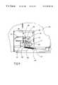
- FIG. 1is a perspective view of a conventional wheelchair lift wherein the present invention power controlled safety barrier can be incorporated thereto;
- FIG. 2is a top plan view of a platform of a wheelchair lift, showing the present invention power controlled safety barrier incorporated thereto, with a roll stop in an opened position;
- FIG. 3is an enlarged cross-sectional view taken along line 3 — 3 of FIG. 2;
- FIG. 4is an enlarged cross-sectional view taken along line 4 — 4 of FIG. 2;
- FIG. 5is an enlarged cross-sectional view taken along line 5 — 5 of FIG. 2;
- FIG. 6is a top plan view of the platform of the wheelchair lift, showing the present invention power controlled safety barrier incorporated thereto, with the roll stop in a closed position;
- FIG. 7is a side elevational view of one side of the platform, with the roll stop in the opened position;
- FIG. 8is a side elevational view of the same side of the platform shown in FIG. 7, with the roll stop in the closed position;
- FIG. 9is an enlarged plan view of a motor drive assembly
- FIG. 10is a side elevational view of the other side of the platform, with the roll stop in the opened position.
- FIG. 11is a side elevational view of the same other side of the platform shown in FIG. 10, with the roll stop in the closed position.
- a conventional wheelchair liftwhich comprises a platform 22 located in a ground position with an outer roll stop 50 fully opened.
- Two opposite side panels 80 and 180are relatively mounted on opposite sides of the platform 22 to prevent a wheelchair from rolling off the sides of the platform 22 .
- the platform 22can be lifted upwardly and downwardly among a stowed position (not shown), an entry position (not shown) and the ground position by a pair of opposite hydraulic actuators 190 and 290 mounted on two relative parallelogram linkage structures 200 and 300 .
- the wheelchair lift 2can be adapted to have the present invention power controlled safety barrier or power roll stop. It will be appreciated that the present invention power controlled safety barrier can be applied to many other kinds of wheelchair lifts which require the outer roll stop 50 .
- FIG. 2depicts the platform 22 incorporated with the present invention power controlled safety barrier or power roll stop 10 , wherein the safety barrier or roll stop 50 is in an opened position.
- FIG. 6depicts the platform 22 incorporated with the present invention power roll stop 10 , wherein the roll stop 50 is in a closed position.
- the power roll stop 10comprises a motor drive assembly 14 , a linkage mechanism 28 , and a safety barrier or roll stop 50 .
- the power roll stop 10can be used in conjunction with and mounted within the wheelchair lift 2 (see FIG. 1) which comprises the platform 22 having an outer edge 26 .
- the platform 22has a build-in disc type small enclosure 25 located on one side of the platform 22 to accommodate the motor drive assembly 14 which powers the power roll stop 10 .
- a top cover(not shown) is provided for covering the enclosure 25 and coplanar to an upper surface of the platform 22 .
- the motor drive assembly 14comprises a motor bracket 24 which is mounted in the enclosure 25 , an electrical motor 16 mounted on the bracket 24 , a driving gear 18 rotatably mounted on a driving shaft of the motor 16 , and a driven gear 20 rotatably mounted on the motor bracket 24 .
- Each gearhas teeth for engaging with each other.
- the driving gear 18 and driven gear 20have formed a required output torque and speed.
- a radial groove type opening 12is provided on the driven gear 20 to define a rotation range for the driven gear 20 .
- a stop roller on stud 15fixed on the motor bracket 24 and is adapted to receive within the radial groove opening 12 to terminate the rotational movement of the driven gear 20 when the stop roller 15 engages ends 17 and 19 formed on the groove opening 12 .
- the linkage mechanism 28is mounted within one side mounting frame bar 42 of the platform 22 .
- the linkage mechanism 28comprises an elongated proximal linkage bar 30 , an elongated distal linkage bar 35 , and a flexible linkage member 60 , preferably a spring.
- the proximal 30 and distal 35 linkage barsare pivotaly connected at their respective adjacent ends 34 and 32 by a lockable pin means 40 , and substantially extended horizontally on their other ends 37 and 39 .
- the linkage bar 35is located above the side mounting frame bar 42 of the platform 22 , where the inner end 32 extends inside of the side mounting frame bar 42 through a slot opening 54 formed on top of the side mounting frame bar 42 to pivotally connect to the outer end 34 of the proximal linkage bar 30 .
- the outer end 39is pivotally connected to a fixed anchor 66 which is mounted on and projected outwardly from the roll stop 50 (see FIGS. 2 and 6 ).
- the proximal linkage bar 30is mounted inside of the side mounting frame bar 42 and is slidably received within a guide bushing 55 which is fixed relative to an inner wall of the side mounting frame bar 42 by a pair of brackets 56 and 58 (see FIGS. 2 and 5 ).
- the flexible spring 60is connected between the motor drive assembly 14 and the two linkage bars 30 and 35 .
- the flexible spring 60is designed and manufactured in a certain way so that it is rigid enough to transfer the thrust force from the motor drive assembly 14 to the linkage bars 30 and 35 to move the roll stop 50 to the closed or opened position.
- the two opposite ends of the flexible spring 60are respectively connected to a thumb shaped projected portion 62 on the driven gear 20 and the inner end 37 of the proximal linkage bar 30 through an “” shaped bracket 64 .
- the motor 16is activated to move the driving gear 18 which in turn rotates the driven gear 20 in a clockwise or a counter-clockwise direction for moving the roll stop 50 between an open and closed position.
- the driven gear 20rotates clockwise to activate the flexible spring 60 which in turn pulls the linkage bars 30 and 35 for moving the roll stop 50 to the closed position (see FIGS. 6 and 8 ).
- the opening 12 on the driven gear 20is configured in such a way that when the driven gear 20 stops at end 19 of the opening 12 during the clockwise rotation, the roll stop 50 is in the fully closed position which is usually substantially vertical to the platform 22 .
- the flexible spring 60When the roll stop 50 is closed, it is preferred that the flexible spring 60 is in its nominal length as to have the least thrust force applied on the linkage bars 30 , 35 and the roll stop 50 in the open direction. It is preferable not to have the excessive force in the power roll stop system to open the roll stop 50 while it is in the closed position.
- the driven gear 20rotates counter-clockwise, it stops at end 17 on the radial groove opening 12 to more the roll stop 50 to the fully open position which is substantially horizontal and is to be an extension of the platform 22 . In this position, it is required that the flexible spring 60 is compressed until ideally bent towards the interior side of the platform 22 .
- the spring 60 , the radial groove opening 12 and the thumb portion 62 on the driven gear 20need to be properly designed and mounted.
- the flexible spring 50exerts a moderate amount of thrust force applied to the linkage bar 30 , 35 and the roll stop 50 in the open direction.
- this element 60should be rigid enough to enable it to transfer forces between the actuating means 14 and the linkage members 30 and 35 for opening and closing the roll stop 50 under the normal power operation.
- the element 60should have enough flexibility to be extendible if the manual operation is required in some situations such as backup operations for the power failure.
- an extension spring 60is utilized which makes it possible for the roll stop 50 to be operational by both power and manual controls.
- the spring 60(shown in the FIG. 6) is preferred to be in its nominal length or may be slightly extended while the roll stop 50 is in the fully closed position which allows extension of the spring 60 to more the roll stop 50 to the opened position under a manual force.
- the spring 50is bent in order to facilitate the movement of the roll stop 50 to the closed position by manual operation, in which the spring 60 may be further bent.
- the flexible spring 60may be an extension spring, part number S-599, commercially available from Century Spring Corporation located in Los Angeles.
- additional mechanical locking mechanismsare relatively mounted on both outer front ends of the side mounting frame bars 42 and 142 .
- Two opposite mechanical locking mechanismsare provided located respectively in the front end of the side mounting frame bars 42 and 142 . Since those two locking mechanisms are substantially identical, only one will be described in detail.
- the locking mechanism in the side mounting frame bar 42comprises a ski member 70 which is spring loaded and pivotally mounted on the front end of the side mounting frame bar 42 and a latch foot 52 which is fixed on the roll stop 50 .
- a ski member 70which is spring loaded and pivotally mounted on the front end of the side mounting frame bar 42 and a latch foot 52 which is fixed on the roll stop 50 .
- the roll stop 50When the roll stop 50 is in the fully closed position, it is automatically locked by the ski member 70 , which latches to the latch foot 52 (see FIG. 8 ), where the lower side of the ski member 70 forms a ski plate 72 maintained in a download acute angle relative to the horizontal plane during the lift's loading operation.
- the ski plate 72 of the ski member 70contacts the ground first and pivot counter-clockwisely to the horizontal plane as to unlock the ski member 70 form the latch foot 52 so that it allows the roll stop 50 to unlock first and then rotate to the fully opened position under the normal power controlled operation described previously.
- FIGS. 10 and 11it shows the other side of the platform 22 of the wheelchair lift 2 , where another ski member 170 is located on the side mounting frame bar 142 and latches to the latch foot 152 to lock the roll stop 50 in the closed position.
- an electric control meansis provided to conditionally activate the power for the motor means of the roll stop system and the power source of the whole lift upon the positions of the platform so that the power operations of the lift and the roll stop will be sequentially controlled and will not interfere with each other.
- the position limit switch 74is to control the motor drive assembly 14 .
- the position limit switch 76is to control the lift motor control.
- these two limit switches 74 and 76are connected to a main lift electrical control circuit (not shown) and mechanically should not be actuated at the same time to avoid the motion interference.
- the switch 74is positioned in such a way that it may be actuated only when the platform 22 has reached the ground position.
- the switch 76is positioned in a way that it may be actuated only when the roll top 50 is in the fully closed position. More specifically, in the fully closed position shown in the FIG. 11, the lift can be operated but the roll stop 50 is unable to move under the power controlled mode. Referring to FIG. 10, when the lift has reached the ground position, the roll stop 50 is able to move by the motor drive assembly 14 while the lift operation is disabled.
- the manual control for the power roll stop 10is not necessary unless an emergency situation occurs such as the power or the motor drive assembly 14 becomes inoperable.
- To manually open the roll stop 50(assuming it is from the fully closed position), pivot the ski members 70 and 170 upwardly to release the mechanical locking mechanism between the ski members 70 and 170 and the latch feet 52 and 52 and then naturally rotate the roll stop 50 to the open position.
- One of the unique features of the present invention power controlled safety barrieris that due to the spring member 60 , no additional parts, tools or other assembling, disassembling operations are required in the manual operation.
- the present inventionis a wheelchair lift, comprising: (a) a platform having an outer entrance edge; (b) a roll stop pivotably connected on the outer edge of the platform, where the roll stop is moveable between an opened position when the platform engages the ground for permitting movement of the wheelchair over the roll stop and across the platform edge, and a closed position for physically blocking movement of the wheelchair across the platform edge when the platform is away from the ground; (c) a linkage mechanism including an elongated distal linkage bar, an elongated proximal linkage bar, and a flexible spring member, the proximal and distal linkage bars pivotally coupled to each other at adjacent ends, the free end of the distal linkage bar pivotally coupled to the roll stop, and the free end of the proximal linkage bar connected to the flexible spring member; (d) a motor drive assembly including a motor, a driving gear electrically coupled to the motor, and a driven gear engaged with the driving gear and connected to the other end of the flexible spring member, such that when
- the present inventionis a platform safety barrier used in conjunction with a wheelchair lift for preventing a wheelchair from inadvertent movement across an outer edge of the platform, the barrier comprising: (a) a roll stop pivotable on the outer edge of the platform, where the roll stop is moveable between an opened position when the platform engages the ground for permitting movement of the wheelchair over the roll stop and across the platform edge, and a closed position for physically blocking movement of the wheelchair across the platform edge when the platform is away from the ground; (b) a linkage mechanism including a distal linkage bar, a proximal linkage bar, and a flexible spring means, the proximal and distal linkage bars pivotally coupled to the roll stop, and the free end of the proximal linkage bar connected to the flexible spring means; (c) a motor drive assembly including a motor, a driving gear coupled to the motor, and a driven gear engaged with the driving gear and connected to the other end of the flexible spring means, such that when the motor is actuated, it rotates the
- the present inventionis a platform safety barrier used in conjunction with a wheelchair lift for preventing a wheelchair from inadvertent movement across an outer edge of the platform, the barrier comprising: (a) a roll stop means pivotably mounted on the outer edge of the platform, where the roll stop means is moveable between an opened position when the platform engages the ground for permitting movement of the wheelchair over the roll stop means and across the platform edge, and a closed position for physically blocking movement of the wheelchair across the platform edge when the platform is away from the ground; (b) a linkage mechanism including a pair of linkage members pivotally coupled to each other at adjacent ends and a flexible linkage member, the free end of the one of the pair of linkage members pivotally coupled to the roll top means, the free end of the other one of the pair of linkage members connected to the flexible linkage member; and (c) an actuating means connected to the other end of the flexible linkage member such that when the actuating means activates the flexible linkage member, the roll stop means moves to the opened position or to the closed
- the present inventionis a platform safety barrier used in conjunction with a wheelchair lift for preventing a wheelchair from inadvertent movement across an outer edge of the platform, the barrier comprising: (a) a roll stop means pivotally mounted on the outer edge of the platform and moveable between an opened position and a closed position; (b) an actuating means; and (c) a linkage mechanism connecting the actuating means and the roll stop means, the linkage mechanism includes a flexible linkage member for permitting both powered and manual operations of the roll stop means between the opened and closed positions.
Landscapes
- Engineering & Computer Science (AREA)
- Transportation (AREA)
- Mechanical Engineering (AREA)
- Health & Medical Sciences (AREA)
- Public Health (AREA)
- Life Sciences & Earth Sciences (AREA)
- Animal Behavior & Ethology (AREA)
- General Health & Medical Sciences (AREA)
- Veterinary Medicine (AREA)
- Power-Operated Mechanisms For Wings (AREA)
Abstract
Description
Claims (24)
Priority Applications (1)
| Application Number | Priority Date | Filing Date | Title |
|---|---|---|---|
| US08/958,651US6203266B1 (en) | 1997-10-27 | 1997-10-27 | Power safety barrier for wheelchair lift |
Applications Claiming Priority (1)
| Application Number | Priority Date | Filing Date | Title |
|---|---|---|---|
| US08/958,651US6203266B1 (en) | 1997-10-27 | 1997-10-27 | Power safety barrier for wheelchair lift |
Publications (1)
| Publication Number | Publication Date |
|---|---|
| US6203266B1true US6203266B1 (en) | 2001-03-20 |
Family
ID=25501154
Family Applications (1)
| Application Number | Title | Priority Date | Filing Date |
|---|---|---|---|
| US08/958,651Expired - LifetimeUS6203266B1 (en) | 1997-10-27 | 1997-10-27 | Power safety barrier for wheelchair lift |
Country Status (1)
| Country | Link |
|---|---|
| US (1) | US6203266B1 (en) |
Cited By (30)
| Publication number | Priority date | Publication date | Assignee | Title |
|---|---|---|---|---|
| US6305897B1 (en) | 1997-06-11 | 2001-10-23 | The Braun Corporation | Multi-panel platform rollstops for wheelchair lift |
| WO2002009971A1 (en)* | 2000-07-27 | 2002-02-07 | Thyssen De Reus B.V. | Platform with ramp |
| US6398479B1 (en) | 2000-05-03 | 2002-06-04 | The Braun Corporation | Under-vehicle lift with folding platform |
| US20030213653A1 (en)* | 2002-02-28 | 2003-11-20 | Lift-U, A Division Of Hogan Mfg., Inc. | Wheelchair lift for a stage |
| US20040146386A1 (en)* | 2003-01-29 | 2004-07-29 | Goodrich Ronald W. | Wheelchair access system with stacking platform |
| US20040228713A1 (en)* | 2003-02-19 | 2004-11-18 | Alan Cohn | Wheelchair lift assembly having a compact stowed profile |
| EP1520570A1 (en)* | 2003-09-30 | 2005-04-06 | Axess Srl | Actuator assembly for a lifter device for disabled persons on wheelchair and prams for children |
| US20060182570A1 (en)* | 2004-12-30 | 2006-08-17 | Eric Zuercher | Portable wheel chair lift |
| US20070183881A1 (en)* | 2006-02-03 | 2007-08-09 | Ricon Corp. | Wheelchair lift with slidable support arm |
| US20070183880A1 (en)* | 2006-02-03 | 2007-08-09 | Ricon Corp. | Slidably collapsible two arm wheel chair lift |
| US20080308358A1 (en)* | 2007-06-14 | 2008-12-18 | Eric Zuercher | Wheel chair lift with protective skirt sensors |
| US20080308357A1 (en)* | 2007-06-14 | 2008-12-18 | Coble James T Tim | Permanently-installed wheel chair lift with height control |
| US7500818B1 (en)* | 2003-12-04 | 2009-03-10 | Lift-U, Division Of Hogan Mfg., Inc. | Passenger lift with passenger sensitive moveable barrier |
| US8113760B1 (en) | 2008-05-12 | 2012-02-14 | Sean Schroll | Secure loading system |
| USD668422S1 (en)* | 2011-04-13 | 2012-10-02 | Bruno Independent Living Aids, Inc. | Platform lift trailer |
| US8783419B2 (en) | 2011-11-03 | 2014-07-22 | Agm Container Controls, Inc. | Low profile wheelchair lift with direct-acting hydraulic cylinders |
| US20140308101A1 (en)* | 2013-04-11 | 2014-10-16 | BROSTOR, naamloze vennootschap | Lift for a bicycle rack or luggage rack |
| US8926253B2 (en) | 2010-04-14 | 2015-01-06 | Bruno Independent Living Aids, Inc. | Platform lift trailer and coupling system |
| US8973713B2 (en) | 2011-11-03 | 2015-03-10 | Agm Container Controls, Inc. | Height adjustment system for wheelchair lift |
| US9051156B2 (en) | 2011-11-03 | 2015-06-09 | Agm Container Controls, Inc. | Wheelchair lift device with pinned floor struts |
| USD801619S1 (en)* | 2016-05-27 | 2017-10-31 | The Braun Corporation | Vertical channel vehicle lift arm |
| WO2018088802A1 (en)* | 2016-11-10 | 2018-05-17 | Samsung Electronics Co., Ltd. | Lifting device and refrigerator including the same |
| KR20180052516A (en)* | 2016-11-10 | 2018-05-18 | 삼성전자주식회사 | Lifting device and refrigerator including the same |
| US10195977B2 (en) | 2016-05-27 | 2019-02-05 | The Braun Corporation | Parallelogram arm vehicle lift |
| USD863710S1 (en)* | 2018-02-19 | 2019-10-15 | Michael Stoner | Combined tilt loader and carrier |
| US10695238B2 (en) | 2018-09-17 | 2020-06-30 | Charlie Homer Thompson | Mountable elevator |
| US10945896B1 (en) | 2019-04-25 | 2021-03-16 | Mpower Mobility, Inc | Platform lift with enhanced occupant sensing, platform lighting and locking |
| USD924780S1 (en) | 2019-07-23 | 2021-07-13 | Michael Stoner | Tilt loading game carrier |
| US20220219589A1 (en)* | 2021-01-13 | 2022-07-14 | Toyota Jidosha Kabushiki Kaisha | Vehicle equipped with slope device |
| US11504285B2 (en)* | 2019-10-02 | 2022-11-22 | Roxana Developments Limited | Wheelchair lift bridge plate catch |
Citations (11)
| Publication number | Priority date | Publication date | Assignee | Title |
|---|---|---|---|---|
| US4124130A (en) | 1977-02-28 | 1978-11-07 | Collins Industries, Inc. | Safety barrier for a wheelchair lift |
| US4442921A (en) | 1981-02-23 | 1984-04-17 | Reb Manufacturing, Inc. | Lift platform automatic ramp barrier |
| US4556128A (en) | 1975-08-20 | 1985-12-03 | Lift-U-Inc. | Wheelchair lift |
| US4907936A (en)* | 1988-08-18 | 1990-03-13 | Joyride Company | Wheelchair lift for vehicles |
| US4984955A (en)* | 1989-02-23 | 1991-01-15 | Mccullough Robert C | Lift apparatus |
| US5040936A (en) | 1990-02-21 | 1991-08-20 | Mobile-Tech Corporation | Barrier for lift platform |
| US5105915A (en)* | 1990-12-24 | 1992-04-21 | Gary Jerry M | Wheelchair lifting device |
| US5180275A (en)* | 1991-05-28 | 1993-01-19 | The Braun Corporation | Rotary bus lift with power stowable platform |
| US5401135A (en) | 1994-01-14 | 1995-03-28 | Crow River Industries | Foldable platform wheelchair lift with safety barrier |
| US5439342A (en) | 1994-02-18 | 1995-08-08 | All American Transit Parts, Inc. | Safety barrier/ramp actuating mechanism for wheelchair lifts |
| US5556250A (en) | 1988-11-05 | 1996-09-17 | Ricon Corporation | Vehicle lifts |
- 1997
- 1997-10-27USUS08/958,651patent/US6203266B1/ennot_activeExpired - Lifetime
Patent Citations (11)
| Publication number | Priority date | Publication date | Assignee | Title |
|---|---|---|---|---|
| US4556128A (en) | 1975-08-20 | 1985-12-03 | Lift-U-Inc. | Wheelchair lift |
| US4124130A (en) | 1977-02-28 | 1978-11-07 | Collins Industries, Inc. | Safety barrier for a wheelchair lift |
| US4442921A (en) | 1981-02-23 | 1984-04-17 | Reb Manufacturing, Inc. | Lift platform automatic ramp barrier |
| US4907936A (en)* | 1988-08-18 | 1990-03-13 | Joyride Company | Wheelchair lift for vehicles |
| US5556250A (en) | 1988-11-05 | 1996-09-17 | Ricon Corporation | Vehicle lifts |
| US4984955A (en)* | 1989-02-23 | 1991-01-15 | Mccullough Robert C | Lift apparatus |
| US5040936A (en) | 1990-02-21 | 1991-08-20 | Mobile-Tech Corporation | Barrier for lift platform |
| US5105915A (en)* | 1990-12-24 | 1992-04-21 | Gary Jerry M | Wheelchair lifting device |
| US5180275A (en)* | 1991-05-28 | 1993-01-19 | The Braun Corporation | Rotary bus lift with power stowable platform |
| US5401135A (en) | 1994-01-14 | 1995-03-28 | Crow River Industries | Foldable platform wheelchair lift with safety barrier |
| US5439342A (en) | 1994-02-18 | 1995-08-08 | All American Transit Parts, Inc. | Safety barrier/ramp actuating mechanism for wheelchair lifts |
Cited By (49)
| Publication number | Priority date | Publication date | Assignee | Title |
|---|---|---|---|---|
| US6305897B1 (en) | 1997-06-11 | 2001-10-23 | The Braun Corporation | Multi-panel platform rollstops for wheelchair lift |
| US6398479B1 (en) | 2000-05-03 | 2002-06-04 | The Braun Corporation | Under-vehicle lift with folding platform |
| US20040107520A1 (en)* | 2000-07-27 | 2004-06-10 | Van Der Heiden Arnoldus Theodorus | Platform with ramp |
| WO2002009971A1 (en)* | 2000-07-27 | 2002-02-07 | Thyssen De Reus B.V. | Platform with ramp |
| US20030213653A1 (en)* | 2002-02-28 | 2003-11-20 | Lift-U, A Division Of Hogan Mfg., Inc. | Wheelchair lift for a stage |
| US20060018743A1 (en)* | 2003-01-29 | 2006-01-26 | The Braun Corporation | Wheelchair access system with stacking platform |
| US6837670B2 (en) | 2003-01-29 | 2005-01-04 | The Braun Corporation | Wheelchair access system with stacking platform |
| US20040146386A1 (en)* | 2003-01-29 | 2004-07-29 | Goodrich Ronald W. | Wheelchair access system with stacking platform |
| US7413395B2 (en) | 2003-01-29 | 2008-08-19 | The Braun Corporation | Wheelchair access system with stacking platform |
| US7419349B2 (en) | 2003-01-29 | 2008-09-02 | The Braun Corporation | Wheelchair access system with stacking platform |
| US20040228713A1 (en)* | 2003-02-19 | 2004-11-18 | Alan Cohn | Wheelchair lift assembly having a compact stowed profile |
| US7326024B2 (en)* | 2003-02-19 | 2008-02-05 | Lift-U, Division Of Hogan Mfg., Inc. | Wheelchair lift assembly having a compact stowed profile |
| EP1520570A1 (en)* | 2003-09-30 | 2005-04-06 | Axess Srl | Actuator assembly for a lifter device for disabled persons on wheelchair and prams for children |
| US7500818B1 (en)* | 2003-12-04 | 2009-03-10 | Lift-U, Division Of Hogan Mfg., Inc. | Passenger lift with passenger sensitive moveable barrier |
| US20060182570A1 (en)* | 2004-12-30 | 2006-08-17 | Eric Zuercher | Portable wheel chair lift |
| US8739935B2 (en) | 2004-12-30 | 2014-06-03 | Agm Container Controls, Inc. | Portable wheel chair lift |
| US20110174579A1 (en)* | 2004-12-30 | 2011-07-21 | Agm Container Controls, Inc. | Portable wheel chair lift |
| US7926618B2 (en) | 2004-12-30 | 2011-04-19 | Agm Container Controls, Inc. | Portable wheel chair lift |
| US20070183880A1 (en)* | 2006-02-03 | 2007-08-09 | Ricon Corp. | Slidably collapsible two arm wheel chair lift |
| US7445416B2 (en) | 2006-02-03 | 2008-11-04 | Ricon Corp. | Wheelchair lift with slidable support arm |
| US7467917B2 (en) | 2006-02-03 | 2008-12-23 | Ricon Corporation | Slidably collapsible two arm wheelchair lift |
| US20090129906A1 (en)* | 2006-02-03 | 2009-05-21 | Ricon Corp. | Method of Stowing Wheelchair Lift |
| US20070183881A1 (en)* | 2006-02-03 | 2007-08-09 | Ricon Corp. | Wheelchair lift with slidable support arm |
| US7815413B2 (en) | 2006-02-03 | 2010-10-19 | Ricon Corp. | Method of stowing wheelchair lift |
| US7721850B2 (en) | 2007-06-14 | 2010-05-25 | Agm Container Controls, Inc. | Permanently-installed wheel chair lift with height control |
| US20080308358A1 (en)* | 2007-06-14 | 2008-12-18 | Eric Zuercher | Wheel chair lift with protective skirt sensors |
| US8079447B2 (en) | 2007-06-14 | 2011-12-20 | Agm Container Controls, Inc. | Wheel chair lift with protective skirt sensors |
| US20080308357A1 (en)* | 2007-06-14 | 2008-12-18 | Coble James T Tim | Permanently-installed wheel chair lift with height control |
| US8113760B1 (en) | 2008-05-12 | 2012-02-14 | Sean Schroll | Secure loading system |
| US8926253B2 (en) | 2010-04-14 | 2015-01-06 | Bruno Independent Living Aids, Inc. | Platform lift trailer and coupling system |
| US9505594B2 (en) | 2010-04-14 | 2016-11-29 | Bruno Independent Living Aids, Inc. | Platform lift trailer and coupling system |
| USD668422S1 (en)* | 2011-04-13 | 2012-10-02 | Bruno Independent Living Aids, Inc. | Platform lift trailer |
| US8973713B2 (en) | 2011-11-03 | 2015-03-10 | Agm Container Controls, Inc. | Height adjustment system for wheelchair lift |
| US9051156B2 (en) | 2011-11-03 | 2015-06-09 | Agm Container Controls, Inc. | Wheelchair lift device with pinned floor struts |
| US8783419B2 (en) | 2011-11-03 | 2014-07-22 | Agm Container Controls, Inc. | Low profile wheelchair lift with direct-acting hydraulic cylinders |
| US20140308101A1 (en)* | 2013-04-11 | 2014-10-16 | BROSTOR, naamloze vennootschap | Lift for a bicycle rack or luggage rack |
| USD801619S1 (en)* | 2016-05-27 | 2017-10-31 | The Braun Corporation | Vertical channel vehicle lift arm |
| US10195977B2 (en) | 2016-05-27 | 2019-02-05 | The Braun Corporation | Parallelogram arm vehicle lift |
| WO2018088802A1 (en)* | 2016-11-10 | 2018-05-17 | Samsung Electronics Co., Ltd. | Lifting device and refrigerator including the same |
| KR20180052516A (en)* | 2016-11-10 | 2018-05-18 | 삼성전자주식회사 | Lifting device and refrigerator including the same |
| US10234195B2 (en) | 2016-11-10 | 2019-03-19 | Samsung Electronics Co., Ltd. | Lifting device and refrigerator including the same |
| USD863710S1 (en)* | 2018-02-19 | 2019-10-15 | Michael Stoner | Combined tilt loader and carrier |
| US10695238B2 (en) | 2018-09-17 | 2020-06-30 | Charlie Homer Thompson | Mountable elevator |
| US10945896B1 (en) | 2019-04-25 | 2021-03-16 | Mpower Mobility, Inc | Platform lift with enhanced occupant sensing, platform lighting and locking |
| US12167986B2 (en) | 2019-04-25 | 2024-12-17 | Mpower Mobility, Inc. | Platform lift with enhanced occupant sensing, platform lifting and locking |
| USD924780S1 (en) | 2019-07-23 | 2021-07-13 | Michael Stoner | Tilt loading game carrier |
| US11504285B2 (en)* | 2019-10-02 | 2022-11-22 | Roxana Developments Limited | Wheelchair lift bridge plate catch |
| US20220219589A1 (en)* | 2021-01-13 | 2022-07-14 | Toyota Jidosha Kabushiki Kaisha | Vehicle equipped with slope device |
| US11970101B2 (en)* | 2021-01-13 | 2024-04-30 | Toyota Jidosha Kabushiki Kaisha | Vehicle equipped with slope device |
Similar Documents
| Publication | Publication Date | Title |
|---|---|---|
| US6203266B1 (en) | Power safety barrier for wheelchair lift | |
| US5180275A (en) | Rotary bus lift with power stowable platform | |
| US3874527A (en) | Vehicle mounted access ramp for wheelchair users | |
| US4759682A (en) | Vehicle entrance ramp | |
| US6860701B2 (en) | Wheelchair ramp with side barriers | |
| US4664584A (en) | Rotary wheelchair lift | |
| US5373915A (en) | Passenger lift with an electric safety interlock | |
| US4685858A (en) | Vehicle entrance ramp | |
| AU2003202922B2 (en) | Safety belt system for wheelchair lifts | |
| US5542811A (en) | Wheelchair lift with laterally displaceable support post for vertical and rotational displacement | |
| CA2081026C (en) | Wheelchair lift for transit vehicles having elevated passenger compartment floor | |
| US4804308A (en) | Wheelchair lift | |
| US5651576A (en) | Slewing machine | |
| US20040228713A1 (en) | Wheelchair lift assembly having a compact stowed profile | |
| US20030071434A1 (en) | Dual function passenger access system for a vehicle | |
| WO1999008641A9 (en) | Foldable platform wheelchair lift | |
| US5165839A (en) | Wheelchair lift for railway cars | |
| US6223364B1 (en) | Multi-motion lifting and transferring apparatus and method | |
| JPS6349653B2 (en) | ||
| EP1542638A2 (en) | A lift mechanism for a sealing device | |
| JPH08113073A (en) | Get on/off device for vehicle | |
| JP4321183B2 (en) | Wheelchair loading / unloading device | |
| EP3560470A1 (en) | Wheelchair lift safety barrier | |
| JP2004210020A (en) | Wheelchair lift | |
| JP2003220093A (en) | Wheelchair lifter device for railway vehicles |
Legal Events
| Date | Code | Title | Description |
|---|---|---|---|
| AS | Assignment | Owner name:RICON CORPORATION, A CALIFORNIA CORPORATION, CALIF Free format text:ASSIGNMENT OF ASSIGNORS INTEREST;ASSIGNORS:SAVARIA, PIERRE;DELEO, DANTE VINCENT;REEL/FRAME:008868/0367;SIGNING DATES FROM 19971014 TO 19971020 | |
| AS | Assignment | Owner name:RICON CORPORATION, CALIFORNIA Free format text:CHANGE OF ADDRESS;ASSIGNOR:RICON CORPORATION;REEL/FRAME:010243/0635 Effective date:19990719 | |
| AS | Assignment | Owner name:RICON CORPORATION, CALIFORNIA Free format text:CHANGE OF NAME;ASSIGNOR:RICON CORPORATION;REEL/FRAME:010131/0746 Effective date:19990719 | |
| STCF | Information on status: patent grant | Free format text:PATENTED CASE | |
| AS | Assignment | Owner name:MERRILL LYNCH CAPITAL, A DIVISION OF MERRILL LYNCH Free format text:SECURITY INTEREST;ASSIGNOR:RICON CORP.;REEL/FRAME:013589/0496 Effective date:20021213 | |
| FEPP | Fee payment procedure | Free format text:PAYOR NUMBER ASSIGNED (ORIGINAL EVENT CODE: ASPN); ENTITY STATUS OF PATENT OWNER: LARGE ENTITY Free format text:PAT HOLDER CLAIMS SMALL ENTITY STATUS, ENTITY STATUS SET TO SMALL (ORIGINAL EVENT CODE: LTOS); ENTITY STATUS OF PATENT OWNER: LARGE ENTITY | |
| REFU | Refund | Free format text:REFUND - SURCHARGE FOR LATE PAYMENT, LARGE ENTITY (ORIGINAL EVENT CODE: R1554); ENTITY STATUS OF PATENT OWNER: LARGE ENTITY Free format text:REFUND - PAYMENT OF MAINTENANCE FEE, 4TH YEAR, LARGE ENTITY (ORIGINAL EVENT CODE: R1551); ENTITY STATUS OF PATENT OWNER: LARGE ENTITY | |
| FPAY | Fee payment | Year of fee payment:4 | |
| SULP | Surcharge for late payment | ||
| FEPP | Fee payment procedure | Free format text:PAT HOLDER NO LONGER CLAIMS SMALL ENTITY STATUS, ENTITY STATUS SET TO UNDISCOUNTED (ORIGINAL EVENT CODE: STOL); ENTITY STATUS OF PATENT OWNER: LARGE ENTITY | |
| FEPP | Fee payment procedure | Free format text:PAYER NUMBER DE-ASSIGNED (ORIGINAL EVENT CODE: RMPN); ENTITY STATUS OF PATENT OWNER: LARGE ENTITY Free format text:PAYOR NUMBER ASSIGNED (ORIGINAL EVENT CODE: ASPN); ENTITY STATUS OF PATENT OWNER: LARGE ENTITY | |
| FPAY | Fee payment | Year of fee payment:8 | |
| AS | Assignment | Owner name:RICON CORP.,CALIFORNIA Free format text:PATENT RELEASE AND REASSIGNMENT;ASSIGNOR:MERRILL LYNCH CAPITAL, A DIVISION OF MERRILL LYNCH BUSINESS FINANCIAL SERVICES, INC.;REEL/FRAME:024312/0521 Effective date:20070608 | |
| FPAY | Fee payment | Year of fee payment:12 |