US6202442B1 - Integrated apparatus for generating power and/or oxygen enriched fluid and process for the operation thereof - Google Patents
Integrated apparatus for generating power and/or oxygen enriched fluid and process for the operation thereofDownload PDFInfo
- Publication number
- US6202442B1 US6202442B1US09/285,794US28579499AUS6202442B1US 6202442 B1US6202442 B1US 6202442B1US 28579499 AUS28579499 AUS 28579499AUS 6202442 B1US6202442 B1US 6202442B1
- Authority
- US
- United States
- Prior art keywords
- column
- separation unit
- air separation
- air
- sending
- Prior art date
- Legal status (The legal status is an assumption and is not a legal conclusion. Google has not performed a legal analysis and makes no representation as to the accuracy of the status listed.)
- Expired - Lifetime
Links
- QVGXLLKOCUKJST-UHFFFAOYSA-Natomic oxygenChemical compound[O]QVGXLLKOCUKJST-UHFFFAOYSA-N0.000titleclaimsabstractdescription44
- 239000001301oxygenSubstances0.000titleclaimsabstractdescription43
- 229910052760oxygenInorganic materials0.000titleclaimsabstractdescription43
- 238000000034methodMethods0.000titleclaimsdescription30
- 239000012530fluidSubstances0.000titleclaimsdescription10
- IJGRMHOSHXDMSA-UHFFFAOYSA-NAtomic nitrogenChemical compoundN#NIJGRMHOSHXDMSA-UHFFFAOYSA-N0.000claimsabstractdescription170
- 238000000926separation methodMethods0.000claimsabstractdescription87
- 229910052757nitrogenInorganic materials0.000claimsabstractdescription83
- 239000007788liquidSubstances0.000claimsabstractdescription48
- 238000011144upstream manufacturingMethods0.000claimsabstractdescription15
- 239000007789gasSubstances0.000claimsabstractdescription14
- 239000000446fuelSubstances0.000claimsdescription8
- 239000000567combustion gasSubstances0.000claimsdescription6
- 238000010248power generationMethods0.000abstractdescription3
- 241000196324EmbryophytaSpecies0.000description9
- 238000010790dilutionMethods0.000description5
- 239000012895dilutionSubstances0.000description5
- UGFAIRIUMAVXCW-UHFFFAOYSA-NCarbon monoxideChemical compound[O+]#[C-]UGFAIRIUMAVXCW-UHFFFAOYSA-N0.000description4
- 238000002485combustion reactionMethods0.000description4
- 238000004821distillationMethods0.000description4
- 238000003860storageMethods0.000description4
- 239000002699waste materialSubstances0.000description4
- 238000001816coolingMethods0.000description3
- 238000004519manufacturing processMethods0.000description3
- 238000000746purificationMethods0.000description3
- 239000000126substanceSubstances0.000description3
- XKRFYHLGVUSROY-UHFFFAOYSA-NArgonChemical compound[Ar]XKRFYHLGVUSROY-UHFFFAOYSA-N0.000description2
- OKTJSMMVPCPJKN-UHFFFAOYSA-NCarbonChemical compound[C]OKTJSMMVPCPJKN-UHFFFAOYSA-N0.000description2
- 238000004887air purificationMethods0.000description2
- 229910052799carbonInorganic materials0.000description2
- 238000005516engineering processMethods0.000description2
- 238000002156mixingMethods0.000description2
- 239000000203mixtureSubstances0.000description2
- 238000005086pumpingMethods0.000description2
- 238000005057refrigerationMethods0.000description2
- 230000008016vaporizationEffects0.000description2
- QGZKDVFQNNGYKY-AKLPVKDBSA-NAmmonia-N17Chemical compound[17NH3]QGZKDVFQNNGYKY-AKLPVKDBSA-N0.000description1
- 244000025254Cannabis sativaSpecies0.000description1
- MYMOFIZGZYHOMD-UHFFFAOYSA-NDioxygenChemical compoundO=OMYMOFIZGZYHOMD-UHFFFAOYSA-N0.000description1
- 229910052786argonInorganic materials0.000description1
- 238000007906compressionMethods0.000description1
- 230000006835compressionEffects0.000description1
- 230000003247decreasing effectEffects0.000description1
- 239000003546flue gasSubstances0.000description1
- 238000002309gasificationMethods0.000description1
- 238000010791quenchingMethods0.000description1
- 238000010992refluxMethods0.000description1
- 239000002912waste gasSubstances0.000description1
- XLYOFNOQVPJJNP-UHFFFAOYSA-NwaterSubstancesOXLYOFNOQVPJJNP-UHFFFAOYSA-N0.000description1
Images


Classifications
- F—MECHANICAL ENGINEERING; LIGHTING; HEATING; WEAPONS; BLASTING
- F25—REFRIGERATION OR COOLING; COMBINED HEATING AND REFRIGERATION SYSTEMS; HEAT PUMP SYSTEMS; MANUFACTURE OR STORAGE OF ICE; LIQUEFACTION SOLIDIFICATION OF GASES
- F25J—LIQUEFACTION, SOLIDIFICATION OR SEPARATION OF GASES OR GASEOUS OR LIQUEFIED GASEOUS MIXTURES BY PRESSURE AND COLD TREATMENT OR BY BRINGING THEM INTO THE SUPERCRITICAL STATE
- F25J3/00—Processes or apparatus for separating the constituents of gaseous or liquefied gaseous mixtures involving the use of liquefaction or solidification
- F25J3/02—Processes or apparatus for separating the constituents of gaseous or liquefied gaseous mixtures involving the use of liquefaction or solidification by rectification, i.e. by continuous interchange of heat and material between a vapour stream and a liquid stream
- F25J3/04—Processes or apparatus for separating the constituents of gaseous or liquefied gaseous mixtures involving the use of liquefaction or solidification by rectification, i.e. by continuous interchange of heat and material between a vapour stream and a liquid stream for air
- F25J3/04248—Generation of cold for compensating heat leaks or liquid production, e.g. by Joule-Thompson expansion
- F25J3/04254—Generation of cold for compensating heat leaks or liquid production, e.g. by Joule-Thompson expansion using the cold stored in external cryogenic fluids
- F—MECHANICAL ENGINEERING; LIGHTING; HEATING; WEAPONS; BLASTING
- F25—REFRIGERATION OR COOLING; COMBINED HEATING AND REFRIGERATION SYSTEMS; HEAT PUMP SYSTEMS; MANUFACTURE OR STORAGE OF ICE; LIQUEFACTION SOLIDIFICATION OF GASES
- F25J—LIQUEFACTION, SOLIDIFICATION OR SEPARATION OF GASES OR GASEOUS OR LIQUEFIED GASEOUS MIXTURES BY PRESSURE AND COLD TREATMENT OR BY BRINGING THEM INTO THE SUPERCRITICAL STATE
- F25J3/00—Processes or apparatus for separating the constituents of gaseous or liquefied gaseous mixtures involving the use of liquefaction or solidification
- F25J3/02—Processes or apparatus for separating the constituents of gaseous or liquefied gaseous mixtures involving the use of liquefaction or solidification by rectification, i.e. by continuous interchange of heat and material between a vapour stream and a liquid stream
- F25J3/04—Processes or apparatus for separating the constituents of gaseous or liquefied gaseous mixtures involving the use of liquefaction or solidification by rectification, i.e. by continuous interchange of heat and material between a vapour stream and a liquid stream for air
- F25J3/04248—Generation of cold for compensating heat leaks or liquid production, e.g. by Joule-Thompson expansion
- F25J3/04284—Generation of cold for compensating heat leaks or liquid production, e.g. by Joule-Thompson expansion using internal refrigeration by open-loop gas work expansion, e.g. of intermediate or oxygen enriched (waste-)streams
- F25J3/0429—Generation of cold for compensating heat leaks or liquid production, e.g. by Joule-Thompson expansion using internal refrigeration by open-loop gas work expansion, e.g. of intermediate or oxygen enriched (waste-)streams of feed air, e.g. used as waste or product air or expanded into an auxiliary column
- F25J3/04296—Claude expansion, i.e. expanded into the main or high pressure column
- F—MECHANICAL ENGINEERING; LIGHTING; HEATING; WEAPONS; BLASTING
- F25—REFRIGERATION OR COOLING; COMBINED HEATING AND REFRIGERATION SYSTEMS; HEAT PUMP SYSTEMS; MANUFACTURE OR STORAGE OF ICE; LIQUEFACTION SOLIDIFICATION OF GASES
- F25J—LIQUEFACTION, SOLIDIFICATION OR SEPARATION OF GASES OR GASEOUS OR LIQUEFIED GASEOUS MIXTURES BY PRESSURE AND COLD TREATMENT OR BY BRINGING THEM INTO THE SUPERCRITICAL STATE
- F25J3/00—Processes or apparatus for separating the constituents of gaseous or liquefied gaseous mixtures involving the use of liquefaction or solidification
- F25J3/02—Processes or apparatus for separating the constituents of gaseous or liquefied gaseous mixtures involving the use of liquefaction or solidification by rectification, i.e. by continuous interchange of heat and material between a vapour stream and a liquid stream
- F25J3/04—Processes or apparatus for separating the constituents of gaseous or liquefied gaseous mixtures involving the use of liquefaction or solidification by rectification, i.e. by continuous interchange of heat and material between a vapour stream and a liquid stream for air
- F25J3/04248—Generation of cold for compensating heat leaks or liquid production, e.g. by Joule-Thompson expansion
- F25J3/04284—Generation of cold for compensating heat leaks or liquid production, e.g. by Joule-Thompson expansion using internal refrigeration by open-loop gas work expansion, e.g. of intermediate or oxygen enriched (waste-)streams
- F25J3/0429—Generation of cold for compensating heat leaks or liquid production, e.g. by Joule-Thompson expansion using internal refrigeration by open-loop gas work expansion, e.g. of intermediate or oxygen enriched (waste-)streams of feed air, e.g. used as waste or product air or expanded into an auxiliary column
- F25J3/04303—Lachmann expansion, i.e. expanded into oxygen producing or low pressure column
- F—MECHANICAL ENGINEERING; LIGHTING; HEATING; WEAPONS; BLASTING
- F25—REFRIGERATION OR COOLING; COMBINED HEATING AND REFRIGERATION SYSTEMS; HEAT PUMP SYSTEMS; MANUFACTURE OR STORAGE OF ICE; LIQUEFACTION SOLIDIFICATION OF GASES
- F25J—LIQUEFACTION, SOLIDIFICATION OR SEPARATION OF GASES OR GASEOUS OR LIQUEFIED GASEOUS MIXTURES BY PRESSURE AND COLD TREATMENT OR BY BRINGING THEM INTO THE SUPERCRITICAL STATE
- F25J3/00—Processes or apparatus for separating the constituents of gaseous or liquefied gaseous mixtures involving the use of liquefaction or solidification
- F25J3/02—Processes or apparatus for separating the constituents of gaseous or liquefied gaseous mixtures involving the use of liquefaction or solidification by rectification, i.e. by continuous interchange of heat and material between a vapour stream and a liquid stream
- F25J3/04—Processes or apparatus for separating the constituents of gaseous or liquefied gaseous mixtures involving the use of liquefaction or solidification by rectification, i.e. by continuous interchange of heat and material between a vapour stream and a liquid stream for air
- F25J3/04248—Generation of cold for compensating heat leaks or liquid production, e.g. by Joule-Thompson expansion
- F25J3/04284—Generation of cold for compensating heat leaks or liquid production, e.g. by Joule-Thompson expansion using internal refrigeration by open-loop gas work expansion, e.g. of intermediate or oxygen enriched (waste-)streams
- F25J3/04309—Generation of cold for compensating heat leaks or liquid production, e.g. by Joule-Thompson expansion using internal refrigeration by open-loop gas work expansion, e.g. of intermediate or oxygen enriched (waste-)streams of nitrogen
- F25J3/04315—Lowest pressure or impure nitrogen, so-called waste nitrogen expansion
- F—MECHANICAL ENGINEERING; LIGHTING; HEATING; WEAPONS; BLASTING
- F25—REFRIGERATION OR COOLING; COMBINED HEATING AND REFRIGERATION SYSTEMS; HEAT PUMP SYSTEMS; MANUFACTURE OR STORAGE OF ICE; LIQUEFACTION SOLIDIFICATION OF GASES
- F25J—LIQUEFACTION, SOLIDIFICATION OR SEPARATION OF GASES OR GASEOUS OR LIQUEFIED GASEOUS MIXTURES BY PRESSURE AND COLD TREATMENT OR BY BRINGING THEM INTO THE SUPERCRITICAL STATE
- F25J3/00—Processes or apparatus for separating the constituents of gaseous or liquefied gaseous mixtures involving the use of liquefaction or solidification
- F25J3/02—Processes or apparatus for separating the constituents of gaseous or liquefied gaseous mixtures involving the use of liquefaction or solidification by rectification, i.e. by continuous interchange of heat and material between a vapour stream and a liquid stream
- F25J3/04—Processes or apparatus for separating the constituents of gaseous or liquefied gaseous mixtures involving the use of liquefaction or solidification by rectification, i.e. by continuous interchange of heat and material between a vapour stream and a liquid stream for air
- F25J3/04248—Generation of cold for compensating heat leaks or liquid production, e.g. by Joule-Thompson expansion
- F25J3/04333—Generation of cold for compensating heat leaks or liquid production, e.g. by Joule-Thompson expansion using quasi-closed loop internal vapor compression refrigeration cycles, e.g. of intermediate or oxygen enriched (waste-)streams
- F25J3/04339—Generation of cold for compensating heat leaks or liquid production, e.g. by Joule-Thompson expansion using quasi-closed loop internal vapor compression refrigeration cycles, e.g. of intermediate or oxygen enriched (waste-)streams of air
- F—MECHANICAL ENGINEERING; LIGHTING; HEATING; WEAPONS; BLASTING
- F25—REFRIGERATION OR COOLING; COMBINED HEATING AND REFRIGERATION SYSTEMS; HEAT PUMP SYSTEMS; MANUFACTURE OR STORAGE OF ICE; LIQUEFACTION SOLIDIFICATION OF GASES
- F25J—LIQUEFACTION, SOLIDIFICATION OR SEPARATION OF GASES OR GASEOUS OR LIQUEFIED GASEOUS MIXTURES BY PRESSURE AND COLD TREATMENT OR BY BRINGING THEM INTO THE SUPERCRITICAL STATE
- F25J3/00—Processes or apparatus for separating the constituents of gaseous or liquefied gaseous mixtures involving the use of liquefaction or solidification
- F25J3/02—Processes or apparatus for separating the constituents of gaseous or liquefied gaseous mixtures involving the use of liquefaction or solidification by rectification, i.e. by continuous interchange of heat and material between a vapour stream and a liquid stream
- F25J3/04—Processes or apparatus for separating the constituents of gaseous or liquefied gaseous mixtures involving the use of liquefaction or solidification by rectification, i.e. by continuous interchange of heat and material between a vapour stream and a liquid stream for air
- F25J3/04248—Generation of cold for compensating heat leaks or liquid production, e.g. by Joule-Thompson expansion
- F25J3/04333—Generation of cold for compensating heat leaks or liquid production, e.g. by Joule-Thompson expansion using quasi-closed loop internal vapor compression refrigeration cycles, e.g. of intermediate or oxygen enriched (waste-)streams
- F25J3/04351—Generation of cold for compensating heat leaks or liquid production, e.g. by Joule-Thompson expansion using quasi-closed loop internal vapor compression refrigeration cycles, e.g. of intermediate or oxygen enriched (waste-)streams of nitrogen
- F—MECHANICAL ENGINEERING; LIGHTING; HEATING; WEAPONS; BLASTING
- F25—REFRIGERATION OR COOLING; COMBINED HEATING AND REFRIGERATION SYSTEMS; HEAT PUMP SYSTEMS; MANUFACTURE OR STORAGE OF ICE; LIQUEFACTION SOLIDIFICATION OF GASES
- F25J—LIQUEFACTION, SOLIDIFICATION OR SEPARATION OF GASES OR GASEOUS OR LIQUEFIED GASEOUS MIXTURES BY PRESSURE AND COLD TREATMENT OR BY BRINGING THEM INTO THE SUPERCRITICAL STATE
- F25J3/00—Processes or apparatus for separating the constituents of gaseous or liquefied gaseous mixtures involving the use of liquefaction or solidification
- F25J3/02—Processes or apparatus for separating the constituents of gaseous or liquefied gaseous mixtures involving the use of liquefaction or solidification by rectification, i.e. by continuous interchange of heat and material between a vapour stream and a liquid stream
- F25J3/04—Processes or apparatus for separating the constituents of gaseous or liquefied gaseous mixtures involving the use of liquefaction or solidification by rectification, i.e. by continuous interchange of heat and material between a vapour stream and a liquid stream for air
- F25J3/044—Processes or apparatus for separating the constituents of gaseous or liquefied gaseous mixtures involving the use of liquefaction or solidification by rectification, i.e. by continuous interchange of heat and material between a vapour stream and a liquid stream for air using a single pressure main column system only
- F—MECHANICAL ENGINEERING; LIGHTING; HEATING; WEAPONS; BLASTING
- F25—REFRIGERATION OR COOLING; COMBINED HEATING AND REFRIGERATION SYSTEMS; HEAT PUMP SYSTEMS; MANUFACTURE OR STORAGE OF ICE; LIQUEFACTION SOLIDIFICATION OF GASES
- F25J—LIQUEFACTION, SOLIDIFICATION OR SEPARATION OF GASES OR GASEOUS OR LIQUEFIED GASEOUS MIXTURES BY PRESSURE AND COLD TREATMENT OR BY BRINGING THEM INTO THE SUPERCRITICAL STATE
- F25J3/00—Processes or apparatus for separating the constituents of gaseous or liquefied gaseous mixtures involving the use of liquefaction or solidification
- F25J3/02—Processes or apparatus for separating the constituents of gaseous or liquefied gaseous mixtures involving the use of liquefaction or solidification by rectification, i.e. by continuous interchange of heat and material between a vapour stream and a liquid stream
- F25J3/04—Processes or apparatus for separating the constituents of gaseous or liquefied gaseous mixtures involving the use of liquefaction or solidification by rectification, i.e. by continuous interchange of heat and material between a vapour stream and a liquid stream for air
- F25J3/04406—Processes or apparatus for separating the constituents of gaseous or liquefied gaseous mixtures involving the use of liquefaction or solidification by rectification, i.e. by continuous interchange of heat and material between a vapour stream and a liquid stream for air using a dual pressure main column system
- F25J3/04412—Processes or apparatus for separating the constituents of gaseous or liquefied gaseous mixtures involving the use of liquefaction or solidification by rectification, i.e. by continuous interchange of heat and material between a vapour stream and a liquid stream for air using a dual pressure main column system in a classical double column flowsheet, i.e. with thermal coupling by a main reboiler-condenser in the bottom of low pressure respectively top of high pressure column
- F—MECHANICAL ENGINEERING; LIGHTING; HEATING; WEAPONS; BLASTING
- F25—REFRIGERATION OR COOLING; COMBINED HEATING AND REFRIGERATION SYSTEMS; HEAT PUMP SYSTEMS; MANUFACTURE OR STORAGE OF ICE; LIQUEFACTION SOLIDIFICATION OF GASES
- F25J—LIQUEFACTION, SOLIDIFICATION OR SEPARATION OF GASES OR GASEOUS OR LIQUEFIED GASEOUS MIXTURES BY PRESSURE AND COLD TREATMENT OR BY BRINGING THEM INTO THE SUPERCRITICAL STATE
- F25J3/00—Processes or apparatus for separating the constituents of gaseous or liquefied gaseous mixtures involving the use of liquefaction or solidification
- F25J3/02—Processes or apparatus for separating the constituents of gaseous or liquefied gaseous mixtures involving the use of liquefaction or solidification by rectification, i.e. by continuous interchange of heat and material between a vapour stream and a liquid stream
- F25J3/04—Processes or apparatus for separating the constituents of gaseous or liquefied gaseous mixtures involving the use of liquefaction or solidification by rectification, i.e. by continuous interchange of heat and material between a vapour stream and a liquid stream for air
- F25J3/04436—Processes or apparatus for separating the constituents of gaseous or liquefied gaseous mixtures involving the use of liquefaction or solidification by rectification, i.e. by continuous interchange of heat and material between a vapour stream and a liquid stream for air using at least a triple pressure main column system
- F25J3/04442—Processes or apparatus for separating the constituents of gaseous or liquefied gaseous mixtures involving the use of liquefaction or solidification by rectification, i.e. by continuous interchange of heat and material between a vapour stream and a liquid stream for air using at least a triple pressure main column system in a double column flowsheet with a high pressure pre-rectifier
- F—MECHANICAL ENGINEERING; LIGHTING; HEATING; WEAPONS; BLASTING
- F25—REFRIGERATION OR COOLING; COMBINED HEATING AND REFRIGERATION SYSTEMS; HEAT PUMP SYSTEMS; MANUFACTURE OR STORAGE OF ICE; LIQUEFACTION SOLIDIFICATION OF GASES
- F25J—LIQUEFACTION, SOLIDIFICATION OR SEPARATION OF GASES OR GASEOUS OR LIQUEFIED GASEOUS MIXTURES BY PRESSURE AND COLD TREATMENT OR BY BRINGING THEM INTO THE SUPERCRITICAL STATE
- F25J3/00—Processes or apparatus for separating the constituents of gaseous or liquefied gaseous mixtures involving the use of liquefaction or solidification
- F25J3/02—Processes or apparatus for separating the constituents of gaseous or liquefied gaseous mixtures involving the use of liquefaction or solidification by rectification, i.e. by continuous interchange of heat and material between a vapour stream and a liquid stream
- F25J3/04—Processes or apparatus for separating the constituents of gaseous or liquefied gaseous mixtures involving the use of liquefaction or solidification by rectification, i.e. by continuous interchange of heat and material between a vapour stream and a liquid stream for air
- F25J3/04521—Coupling of the air fractionation unit to an air gas-consuming unit, so-called integrated processes
- F25J3/04527—Integration with an oxygen consuming unit, e.g. glass facility, waste incineration or oxygen based processes in general
- F25J3/04539—Integration with an oxygen consuming unit, e.g. glass facility, waste incineration or oxygen based processes in general for the H2/CO synthesis by partial oxidation or oxygen consuming reforming processes of fuels
- F25J3/04545—Integration with an oxygen consuming unit, e.g. glass facility, waste incineration or oxygen based processes in general for the H2/CO synthesis by partial oxidation or oxygen consuming reforming processes of fuels for the gasification of solid or heavy liquid fuels, e.g. integrated gasification combined cycle [IGCC]
- F—MECHANICAL ENGINEERING; LIGHTING; HEATING; WEAPONS; BLASTING
- F25—REFRIGERATION OR COOLING; COMBINED HEATING AND REFRIGERATION SYSTEMS; HEAT PUMP SYSTEMS; MANUFACTURE OR STORAGE OF ICE; LIQUEFACTION SOLIDIFICATION OF GASES
- F25J—LIQUEFACTION, SOLIDIFICATION OR SEPARATION OF GASES OR GASEOUS OR LIQUEFIED GASEOUS MIXTURES BY PRESSURE AND COLD TREATMENT OR BY BRINGING THEM INTO THE SUPERCRITICAL STATE
- F25J3/00—Processes or apparatus for separating the constituents of gaseous or liquefied gaseous mixtures involving the use of liquefaction or solidification
- F25J3/02—Processes or apparatus for separating the constituents of gaseous or liquefied gaseous mixtures involving the use of liquefaction or solidification by rectification, i.e. by continuous interchange of heat and material between a vapour stream and a liquid stream
- F25J3/04—Processes or apparatus for separating the constituents of gaseous or liquefied gaseous mixtures involving the use of liquefaction or solidification by rectification, i.e. by continuous interchange of heat and material between a vapour stream and a liquid stream for air
- F25J3/04521—Coupling of the air fractionation unit to an air gas-consuming unit, so-called integrated processes
- F25J3/04563—Integration with a nitrogen consuming unit, e.g. for purging, inerting, cooling or heating
- F25J3/04575—Integration with a nitrogen consuming unit, e.g. for purging, inerting, cooling or heating for a gas expansion plant, e.g. dilution of the combustion gas in a gas turbine
- F—MECHANICAL ENGINEERING; LIGHTING; HEATING; WEAPONS; BLASTING
- F25—REFRIGERATION OR COOLING; COMBINED HEATING AND REFRIGERATION SYSTEMS; HEAT PUMP SYSTEMS; MANUFACTURE OR STORAGE OF ICE; LIQUEFACTION SOLIDIFICATION OF GASES
- F25J—LIQUEFACTION, SOLIDIFICATION OR SEPARATION OF GASES OR GASEOUS OR LIQUEFIED GASEOUS MIXTURES BY PRESSURE AND COLD TREATMENT OR BY BRINGING THEM INTO THE SUPERCRITICAL STATE
- F25J3/00—Processes or apparatus for separating the constituents of gaseous or liquefied gaseous mixtures involving the use of liquefaction or solidification
- F25J3/02—Processes or apparatus for separating the constituents of gaseous or liquefied gaseous mixtures involving the use of liquefaction or solidification by rectification, i.e. by continuous interchange of heat and material between a vapour stream and a liquid stream
- F25J3/04—Processes or apparatus for separating the constituents of gaseous or liquefied gaseous mixtures involving the use of liquefaction or solidification by rectification, i.e. by continuous interchange of heat and material between a vapour stream and a liquid stream for air
- F25J3/04521—Coupling of the air fractionation unit to an air gas-consuming unit, so-called integrated processes
- F25J3/04593—The air gas consuming unit is also fed by an air stream
- F25J3/046—Completely integrated air feed compression, i.e. common MAC
- F—MECHANICAL ENGINEERING; LIGHTING; HEATING; WEAPONS; BLASTING
- F25—REFRIGERATION OR COOLING; COMBINED HEATING AND REFRIGERATION SYSTEMS; HEAT PUMP SYSTEMS; MANUFACTURE OR STORAGE OF ICE; LIQUEFACTION SOLIDIFICATION OF GASES
- F25J—LIQUEFACTION, SOLIDIFICATION OR SEPARATION OF GASES OR GASEOUS OR LIQUEFIED GASEOUS MIXTURES BY PRESSURE AND COLD TREATMENT OR BY BRINGING THEM INTO THE SUPERCRITICAL STATE
- F25J3/00—Processes or apparatus for separating the constituents of gaseous or liquefied gaseous mixtures involving the use of liquefaction or solidification
- F25J3/02—Processes or apparatus for separating the constituents of gaseous or liquefied gaseous mixtures involving the use of liquefaction or solidification by rectification, i.e. by continuous interchange of heat and material between a vapour stream and a liquid stream
- F25J3/04—Processes or apparatus for separating the constituents of gaseous or liquefied gaseous mixtures involving the use of liquefaction or solidification by rectification, i.e. by continuous interchange of heat and material between a vapour stream and a liquid stream for air
- F25J3/04521—Coupling of the air fractionation unit to an air gas-consuming unit, so-called integrated processes
- F25J3/04593—The air gas consuming unit is also fed by an air stream
- F25J3/04606—Partially integrated air feed compression, i.e. independent MAC for the air fractionation unit plus additional air feed from the air gas consuming unit
- F—MECHANICAL ENGINEERING; LIGHTING; HEATING; WEAPONS; BLASTING
- F25—REFRIGERATION OR COOLING; COMBINED HEATING AND REFRIGERATION SYSTEMS; HEAT PUMP SYSTEMS; MANUFACTURE OR STORAGE OF ICE; LIQUEFACTION SOLIDIFICATION OF GASES
- F25J—LIQUEFACTION, SOLIDIFICATION OR SEPARATION OF GASES OR GASEOUS OR LIQUEFIED GASEOUS MIXTURES BY PRESSURE AND COLD TREATMENT OR BY BRINGING THEM INTO THE SUPERCRITICAL STATE
- F25J3/00—Processes or apparatus for separating the constituents of gaseous or liquefied gaseous mixtures involving the use of liquefaction or solidification
- F25J3/02—Processes or apparatus for separating the constituents of gaseous or liquefied gaseous mixtures involving the use of liquefaction or solidification by rectification, i.e. by continuous interchange of heat and material between a vapour stream and a liquid stream
- F25J3/04—Processes or apparatus for separating the constituents of gaseous or liquefied gaseous mixtures involving the use of liquefaction or solidification by rectification, i.e. by continuous interchange of heat and material between a vapour stream and a liquid stream for air
- F25J3/04521—Coupling of the air fractionation unit to an air gas-consuming unit, so-called integrated processes
- F25J3/04612—Heat exchange integration with process streams, e.g. from the air gas consuming unit
- F25J3/04618—Heat exchange integration with process streams, e.g. from the air gas consuming unit for cooling an air stream fed to the air fractionation unit
- F—MECHANICAL ENGINEERING; LIGHTING; HEATING; WEAPONS; BLASTING
- F25—REFRIGERATION OR COOLING; COMBINED HEATING AND REFRIGERATION SYSTEMS; HEAT PUMP SYSTEMS; MANUFACTURE OR STORAGE OF ICE; LIQUEFACTION SOLIDIFICATION OF GASES
- F25J—LIQUEFACTION, SOLIDIFICATION OR SEPARATION OF GASES OR GASEOUS OR LIQUEFIED GASEOUS MIXTURES BY PRESSURE AND COLD TREATMENT OR BY BRINGING THEM INTO THE SUPERCRITICAL STATE
- F25J3/00—Processes or apparatus for separating the constituents of gaseous or liquefied gaseous mixtures involving the use of liquefaction or solidification
- F25J3/02—Processes or apparatus for separating the constituents of gaseous or liquefied gaseous mixtures involving the use of liquefaction or solidification by rectification, i.e. by continuous interchange of heat and material between a vapour stream and a liquid stream
- F25J3/04—Processes or apparatus for separating the constituents of gaseous or liquefied gaseous mixtures involving the use of liquefaction or solidification by rectification, i.e. by continuous interchange of heat and material between a vapour stream and a liquid stream for air
- F25J3/04763—Start-up or control of the process; Details of the apparatus used
- F25J3/04866—Construction and layout of air fractionation equipments, e.g. valves, machines
- F25J3/04951—Arrangements of multiple air fractionation units or multiple equipments fulfilling the same process step, e.g. multiple trains in a network
- F25J3/04963—Arrangements of multiple air fractionation units or multiple equipments fulfilling the same process step, e.g. multiple trains in a network and inter-connecting equipment within or downstream of the fractionation unit(s)
- F—MECHANICAL ENGINEERING; LIGHTING; HEATING; WEAPONS; BLASTING
- F25—REFRIGERATION OR COOLING; COMBINED HEATING AND REFRIGERATION SYSTEMS; HEAT PUMP SYSTEMS; MANUFACTURE OR STORAGE OF ICE; LIQUEFACTION SOLIDIFICATION OF GASES
- F25J—LIQUEFACTION, SOLIDIFICATION OR SEPARATION OF GASES OR GASEOUS OR LIQUEFIED GASEOUS MIXTURES BY PRESSURE AND COLD TREATMENT OR BY BRINGING THEM INTO THE SUPERCRITICAL STATE
- F25J3/00—Processes or apparatus for separating the constituents of gaseous or liquefied gaseous mixtures involving the use of liquefaction or solidification
- F25J3/02—Processes or apparatus for separating the constituents of gaseous or liquefied gaseous mixtures involving the use of liquefaction or solidification by rectification, i.e. by continuous interchange of heat and material between a vapour stream and a liquid stream
- F25J3/04—Processes or apparatus for separating the constituents of gaseous or liquefied gaseous mixtures involving the use of liquefaction or solidification by rectification, i.e. by continuous interchange of heat and material between a vapour stream and a liquid stream for air
- F25J3/04763—Start-up or control of the process; Details of the apparatus used
- F25J3/04866—Construction and layout of air fractionation equipments, e.g. valves, machines
- F25J3/04969—Retrofitting or revamping of an existing air fractionation unit
- F—MECHANICAL ENGINEERING; LIGHTING; HEATING; WEAPONS; BLASTING
- F25—REFRIGERATION OR COOLING; COMBINED HEATING AND REFRIGERATION SYSTEMS; HEAT PUMP SYSTEMS; MANUFACTURE OR STORAGE OF ICE; LIQUEFACTION SOLIDIFICATION OF GASES
- F25J—LIQUEFACTION, SOLIDIFICATION OR SEPARATION OF GASES OR GASEOUS OR LIQUEFIED GASEOUS MIXTURES BY PRESSURE AND COLD TREATMENT OR BY BRINGING THEM INTO THE SUPERCRITICAL STATE
- F25J2200/00—Processes or apparatus using separation by rectification
- F25J2200/20—Processes or apparatus using separation by rectification in an elevated pressure multiple column system wherein the lowest pressure column is at a pressure well above the minimum pressure needed to overcome pressure drop to reject the products to atmosphere
- F—MECHANICAL ENGINEERING; LIGHTING; HEATING; WEAPONS; BLASTING
- F25—REFRIGERATION OR COOLING; COMBINED HEATING AND REFRIGERATION SYSTEMS; HEAT PUMP SYSTEMS; MANUFACTURE OR STORAGE OF ICE; LIQUEFACTION SOLIDIFICATION OF GASES
- F25J—LIQUEFACTION, SOLIDIFICATION OR SEPARATION OF GASES OR GASEOUS OR LIQUEFIED GASEOUS MIXTURES BY PRESSURE AND COLD TREATMENT OR BY BRINGING THEM INTO THE SUPERCRITICAL STATE
- F25J2200/00—Processes or apparatus using separation by rectification
- F25J2200/70—Refluxing the column with a condensed part of the feed stream, i.e. fractionator top is stripped or self-rectified
- F—MECHANICAL ENGINEERING; LIGHTING; HEATING; WEAPONS; BLASTING
- F25—REFRIGERATION OR COOLING; COMBINED HEATING AND REFRIGERATION SYSTEMS; HEAT PUMP SYSTEMS; MANUFACTURE OR STORAGE OF ICE; LIQUEFACTION SOLIDIFICATION OF GASES
- F25J—LIQUEFACTION, SOLIDIFICATION OR SEPARATION OF GASES OR GASEOUS OR LIQUEFIED GASEOUS MIXTURES BY PRESSURE AND COLD TREATMENT OR BY BRINGING THEM INTO THE SUPERCRITICAL STATE
- F25J2205/00—Processes or apparatus using other separation and/or other processing means
- F25J2205/30—Processes or apparatus using other separation and/or other processing means using a washing, e.g. "scrubbing" or bubble column for purification purposes
- F—MECHANICAL ENGINEERING; LIGHTING; HEATING; WEAPONS; BLASTING
- F25—REFRIGERATION OR COOLING; COMBINED HEATING AND REFRIGERATION SYSTEMS; HEAT PUMP SYSTEMS; MANUFACTURE OR STORAGE OF ICE; LIQUEFACTION SOLIDIFICATION OF GASES
- F25J—LIQUEFACTION, SOLIDIFICATION OR SEPARATION OF GASES OR GASEOUS OR LIQUEFIED GASEOUS MIXTURES BY PRESSURE AND COLD TREATMENT OR BY BRINGING THEM INTO THE SUPERCRITICAL STATE
- F25J2210/00—Processes characterised by the type or other details of the feed stream
- F25J2210/42—Nitrogen
- F—MECHANICAL ENGINEERING; LIGHTING; HEATING; WEAPONS; BLASTING
- F25—REFRIGERATION OR COOLING; COMBINED HEATING AND REFRIGERATION SYSTEMS; HEAT PUMP SYSTEMS; MANUFACTURE OR STORAGE OF ICE; LIQUEFACTION SOLIDIFICATION OF GASES
- F25J—LIQUEFACTION, SOLIDIFICATION OR SEPARATION OF GASES OR GASEOUS OR LIQUEFIED GASEOUS MIXTURES BY PRESSURE AND COLD TREATMENT OR BY BRINGING THEM INTO THE SUPERCRITICAL STATE
- F25J2230/00—Processes or apparatus involving steps for increasing the pressure of gaseous process streams
- F25J2230/42—Processes or apparatus involving steps for increasing the pressure of gaseous process streams the fluid being nitrogen
- F—MECHANICAL ENGINEERING; LIGHTING; HEATING; WEAPONS; BLASTING
- F25—REFRIGERATION OR COOLING; COMBINED HEATING AND REFRIGERATION SYSTEMS; HEAT PUMP SYSTEMS; MANUFACTURE OR STORAGE OF ICE; LIQUEFACTION SOLIDIFICATION OF GASES
- F25J—LIQUEFACTION, SOLIDIFICATION OR SEPARATION OF GASES OR GASEOUS OR LIQUEFIED GASEOUS MIXTURES BY PRESSURE AND COLD TREATMENT OR BY BRINGING THEM INTO THE SUPERCRITICAL STATE
- F25J2235/00—Processes or apparatus involving steps for increasing the pressure or for conveying of liquid process streams
- F25J2235/42—Processes or apparatus involving steps for increasing the pressure or for conveying of liquid process streams the fluid being nitrogen
- F—MECHANICAL ENGINEERING; LIGHTING; HEATING; WEAPONS; BLASTING
- F25—REFRIGERATION OR COOLING; COMBINED HEATING AND REFRIGERATION SYSTEMS; HEAT PUMP SYSTEMS; MANUFACTURE OR STORAGE OF ICE; LIQUEFACTION SOLIDIFICATION OF GASES
- F25J—LIQUEFACTION, SOLIDIFICATION OR SEPARATION OF GASES OR GASEOUS OR LIQUEFIED GASEOUS MIXTURES BY PRESSURE AND COLD TREATMENT OR BY BRINGING THEM INTO THE SUPERCRITICAL STATE
- F25J2245/00—Processes or apparatus involving steps for recycling of process streams
- F25J2245/42—Processes or apparatus involving steps for recycling of process streams the recycled stream being nitrogen
- F—MECHANICAL ENGINEERING; LIGHTING; HEATING; WEAPONS; BLASTING
- F25—REFRIGERATION OR COOLING; COMBINED HEATING AND REFRIGERATION SYSTEMS; HEAT PUMP SYSTEMS; MANUFACTURE OR STORAGE OF ICE; LIQUEFACTION SOLIDIFICATION OF GASES
- F25J—LIQUEFACTION, SOLIDIFICATION OR SEPARATION OF GASES OR GASEOUS OR LIQUEFIED GASEOUS MIXTURES BY PRESSURE AND COLD TREATMENT OR BY BRINGING THEM INTO THE SUPERCRITICAL STATE
- F25J2245/00—Processes or apparatus involving steps for recycling of process streams
- F25J2245/50—Processes or apparatus involving steps for recycling of process streams the recycled stream being oxygen
Definitions
- the present inventionrelates to an integrated apparatus for generating power and/or oxygen-enriched fluid and a process for the operation thereof.
- Airhas the advantage of being free and available everywhere.
- One of the drawbacksis that because air is at atmospheric pressure, it contains a lot of water and CO2 at low partial pressure. And pressure drops in process cycles are energy expensive close to atmospheric pressure. It is the reason why most oil, chemical or petrochemical processes operate in the range of 10-40 bar. The pressure drops are less costly, heat exchange is easier, and the size of plants is reduced, drastically decreasing overall cost.
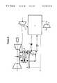
- FIG. 1shows a basic power gas turbine arrangement in which an air compressor 1 sends air 3 at between 8 and 35 bar to a combustor 5 fed by fuel 6 .
- the combustion gas 7 mixed with dilution air 4forms mixture stream 8 which is expanded in gas turbine 9 having an inlet temperature between 900 and 1400° C. and generates power.
- gas turbine 9having an inlet temperature between 900 and 1400° C. and generates power.
- a close to stoichiometric mixingis necessary to use fuel efficiently and produce minimum pollution.
- combustionproduces a hot gas at temperatures higher than 2000° C., well above what any kind of hot turbine can accept.
- quench type coolingtakes place by mixing this very hot flue gas 7 with compressed dilution air 4 from the compressor at the same pressure as stream 3 but much lower temperature.
- the dilution air flow 4is of the same order of magnitude as the combustion air flow 3 .
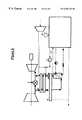
- this dilution air 4does not participate in the combustion, oxygen is not necessary. So it is possible to extract the oxygen contained in the dilution air 4 as shown in FIG. 2 .
- the air 4is cooled, purified and distilled in separation unit 12 producing oxygen 10 and nitrogen 11 .
- the nitrogen 11is mixed with combustion gas 7 .
- the separation unit usedis a double column comprising a thermally linked high pressure column and low pressure column.
- a single columnwith a top condenser and a bottom reboiler for this purpose.
- the amount of nitrogen 11may alternatively be mixed with air stream 3 and sent to combustor 5 as described in U.S. Pat. No. 4,224,045. Another option is to send the nitrogen to be mixed with the fuel stream 6 .
- an integrated apparatus for generating power and/or oxygen enriched fluidcomprising a first air separation unit, a gas turbine comprising a combustor and an expander, a first compressor, means for sending air from the first compressor to the combustor and to the air separation unit, means for sending combustion gases from the combustor to the expander, means for sending nitrogen from the air separation unit to a point upstream of the expander and means for either compressing the nitrogen sent to a point upstream of expander, further compressing the air sent to the first air separation unit from the first compressor or expanding the air sent to the combustor from the first compressor
- the first air separation unitcomprises at least a single column fed by air and the apparatus comprises means for sending liquid nitrogen from an external source to the top of the single column, said external source not being a condenser fed by gaseous nitrogen from the top of the single column, and means for removing gaseous nitrogen from the top of the single column and for removing an oxygen-enriched fluid from the bottom of the column.
- the single columnhas no bottom reboiler and no top condenser
- the apparatuscomprises a second compressor and means for sending air from the further compressor to the single column;
- the external source of liquid nitrogenis a second air separation unit comprising at least one distillation column;
- the second air separation unitcomprises a high pressure column and a low pressure column which are thermally linked;
- the apparatusmay additionally include a gasifier, means for sending oxygen from the air separation unit and a carbon containing substance to the gasifier and means for sending fuel from the gasifier to the combustor.
- a process for generating power and/or oxygen enriched fluid using an integrated power generation systemcomprising compressing air in a first compressor, sending air from the first compressor to a combustor and to a first air separation unit, sending nitrogen from the air separation unit to a point upstream of an expander, sending fuel to the combustor, sending combustion gas from the combustor to the expander and either compressing the nitrogen sent to a point upstream of expander, further compressing the air sent to the first air separation unit from the first compressor or expanding the air sent to the combustor from the first compressor
- the first air separation unitcomprises at least one column and the process comprises feeding a column of the first air separation unit column with air, sending liquid nitrogen from an external source to the top of the single column, the external source not being a condenser fed by gaseous nitrogen from the top of the s column and removing gaseous nitrogen from the top of the single column and an oxygen enriched fluid from the bottom of the column.
- said columnhaving no bottom reboiler and no top condenser
- the external sourcebeing a second air separation unit comprising at least one column
- the external sourcecomprises a high pressure column and a low pressure column which are thermally linked;
- column of the first air separation unitoperates at between 8 and 35 bar
- the highest pressure of the second air separation unitis between 5 and 25 bar;
- the amount of air sent from the first compressor to the first air separation unit and the amount of nitrogen sent upstream of the expanderdiffer by no more than 10%, preferably 5%;
- the nitrogenoriginates from the first air separation unit and the external source
- the external sourceis the second air separation unit.
- the processmay be an integrated gasification combined cycle process in which oxygen from the air separation unit is sent to gasify a carbon containing substance thereby producing fuel for the combustor.
- FIGS. 3 to 6are schematic flow sheets of an integrated air separation unit for use in an integrated power generation system.
- Cryogenic technologyis the basic technology for large air separation plants.
- Airis compressed to between 8 and 35 bar in compressor 1 .
- Air stream 3is sent to combustor 5 where it is burnt with fuel 6 .
- Air stream 4is cooled in heat exchanger 8 , purified in purifying unit 14 and then cooled in heat exchanger 13 to a temperature suitable for cryogenic distillation. It is then sent to a first air separation unit, in this case a wash column 15 which is a single column fed at the top by a liquid nitrogen wash stream 17 which may be pure or contain up to 5% oxygen.
- a wash column 15which is a single column fed at the top by a liquid nitrogen wash stream 17 which may be pure or contain up to 5% oxygen.
- Various sources for the liquidare shown in FIGS. 4 to 6 .
- Liquid containing between 27 to 40% oxygenis removed from the bottom of column 15 .
- Gaseous nitrogen 21is removed from the column at a pressure between 8 and 25 bar, warmed in exchangers 13 , 8 , reactivates air purification 14 , compressed and mixed either with the combustion gas as shown or with air stream 3 .
- the mixture thus formedis sent to expander 9 producing external work
- the nitrogenis compressed in a booster 16 at ambient temperature but may be compressed at sub-ambient or super-ambient temperatures so as to make up for the pressure drop in the exchangers and column.
- air stream 4may be boosted at any of the temperatures described.
- a less economical optionwould be to expand the feed air 3 slightly before sending it to the combustor.
- the nitrogen wash column 15is fed by liquid nitrogen, and very impure oxygen is removed in liquid rich phase. These liquids easily can be pumped and expanded, thus rending this wash totally independent of the rest of the oxygen process;
- gaseous nitrogen flow at the outlet of the wash column 15is almost equal to the air flow at the inlet of this column, thus maintaining the perfect balance of the gas turbine.
- the liquid nitrogen for the wash column 15is derived from a second air separation unit comprising a double column with a high pressure column 25 and a low pressure column 27 thermally linked via a reboiler condenser 29 as in standard plants.
- the systemmay additionally include an argon separation column fed by the low pressure column.
- the operating pressurespreferably vary between 5 and 25 bar for the high pressure column.
- the air for the double columncomes from a compressor 30 and is sent to the high pressure column 25 after cooling in exchanger 33 .
- Oxygen enriched and nitrogen enriched liquidsare sent from the high pressure column to the low pressure column as reflux.
- the systemmay use a Claude turbine, an turbine feeding air to the low pressure column or a nitrogen turbine to produce refrigeration.
- Gaseous oxygenis produced from the low pressure column either directly or by vaporizing liquid oxygen. Waste nitrogen is withdrawn from the low pressure column.
- Liquid nitrogen 17 from the top of the high pressure column 25is sent to the top of wash column 15 following pumping in pump 35 .
- Liquid 37 from the bottom of column 15is expanded in a valve 39 and sent to the bottom of the high pressure column or to the low pressure column.
- a standard cryogenic oxygen planthas a medium pressure column with liquid nitrogen at the top and oxygen rich liquid at the bottom. If one installs a gas turbine next to an oxygen plant to produce electric power (for the oxygen plant or not) or to produce a combination of power and steam (cogeneration), further arrangement can be made.
- some liquid nitrogen or poor liquid 17can be withdrawn from the medium pressure column or any other point of the process such as the low pressure column. It can be pumped to the relevant pressure in order to feed the nitrogen wash column.
- the corresponding rich liquid 37will be returned to the low pressure column as the normal rich liquid.
- some extra oxygen moleculeswill be fed to the column, allowing increased oxygen production (at the same or reduced purity, depending on the boosting ratio).
- the existing purification 14can be used to purify the air.
- a nitrogen (or air) recycle compressor 43is necessary to adjust the separation power requirement of the oxygen separation and compression cycle. To maintain the advantages of the global pressurized cycle, this compressor will preferably receive air or nitrogen at medium pressure (above 3 bar).
- Refrigeration from oxygenwill be recovered in the cold box 41 or within the cold exchanger 13 .
- nitrogen wash columnBecause the gas at the top of nitrogen wash column is nitrogen, it can be used partly 45 to help the final distillation instead of the recycle compressor.
- the flow to the turbinecan be readjusted as before with air or waste nitrogen recompression 47 . It might have an advantage over a nitrogen recycle compressor as this compressed nitrogen will not need any final cooling (FIG. 6 ).
- the external source for the liquid nitrogencould be a remote storage tank periodically replenished by tanker trucks or a liquefier in which gaseous nitrogen e.g. from a pipeline is condensed.
- the oxygen enriched liquid from the first air separation unitmay then be sent to another column or another user, or to liquefy after expansion the gaseous nitrogen from the pipe-line.
- thismay be a single column air separator generating liquid nitrogen, a standard double column with or without minaret, an external condenser of an air separation column, a double column in which oxygen enriched liquid from the bottom of the low pressure column is fed to a top condenser of the low pressure column, a triple column in which rich liquid from a high pressure column feeds a medium pressure column and liquid from the medium pressure column feeds the low pressure column for example of the type shown in FR1061414 or EP538118.
- the second air separation unit serving as an external sourcemay produce other liquids in addition to the nitrogen and other gaseous products. Gases may be produced at high pressure by pumping and vaporizing liquids withdrawn from columns of the second air separation unit.
- One advantage of the present systemis that the first air separation unit and the second air separation unit can operate independently by providing storage tanks for the liquid nitrogen from the second air separation unit and the oxygen enriched liquid from the first air separation unit.
- the first air separation unitdraws liquid nitrogen from the storage.
- the oxygen enriched liquidis removed from the storage and sent to the second air separation unit.
Landscapes
- Engineering & Computer Science (AREA)
- Physics & Mathematics (AREA)
- Mechanical Engineering (AREA)
- Thermal Sciences (AREA)
- General Engineering & Computer Science (AREA)
- Power Engineering (AREA)
- Chemical & Material Sciences (AREA)
- Combustion & Propulsion (AREA)
- Separation By Low-Temperature Treatments (AREA)
Abstract
Description
The present invention relates to an integrated apparatus for generating power and/or oxygen-enriched fluid and a process for the operation thereof.
All present oxygen production facilities extract oxygen from air. Air has the advantage of being free and available everywhere. One of the drawbacks is that because air is at atmospheric pressure, it contains a lot of water and CO2 at low partial pressure. And pressure drops in process cycles are energy expensive close to atmospheric pressure. It is the reason why most oil, chemical or petrochemical processes operate in the range of 10-40 bar. The pressure drops are less costly, heat exchange is easier, and the size of plants is reduced, drastically decreasing overall cost.
In the case of oxygen production, as air contains 80% nitrogen, a low pressure waste gas containing the nitrogen is normally produced. In case of cryogenic distillation, the cold heat contained in the waste nitrogen has to be recuperated through heat exchangers which are costly both in investment and related energy needs.
Some oxygen plants operate at higher than normal pressure with some means and additional investment to recover the energy lost in the waste nitrogen.
FIG. 1 shows a basic power gas turbine arrangement in which an air compressor1 sends air3 at between 8 and 35 bar to a combustor5 fed byfuel 6. Thecombustion gas 7 mixed with dilution air4forms mixture stream 8 which is expanded in gas turbine9 having an inlet temperature between 900 and 1400° C. and generates power. To achieve good combustion in the bumer, a close to stoichiometric mixing is necessary to use fuel efficiently and produce minimum pollution. But in this case, combustion produces a hot gas at temperatures higher than 2000° C., well above what any kind of hot turbine can accept. For this reason, quench type cooling takes place by mixing this veryhot flue gas 7 with compressed dilution air4 from the compressor at the same pressure as stream3 but much lower temperature. The dilution air flow4 is of the same order of magnitude as the combustion air flow3.
Because this dilution air4 does not participate in the combustion, oxygen is not necessary. So it is possible to extract the oxygen contained in the dilution air4 as shown in FIG.2. The air4 is cooled, purified and distilled inseparation unit 12 producingoxygen 10 and nitrogen11. The nitrogen11 is mixed withcombustion gas 7.
Generally the separation unit used is a double column comprising a thermally linked high pressure column and low pressure column. However it is known to use a single column with a top condenser and a bottom reboiler for this purpose.
If the amount of nitrogen11 is limited, it may alternatively be mixed with air stream3 and sent to combustor5 as described in U.S. Pat. No. 4,224,045. Another option is to send the nitrogen to be mixed with thefuel stream 6.
According to the present invention, there is provided an integrated apparatus for generating power and/or oxygen enriched fluid comprising a first air separation unit, a gas turbine comprising a combustor and an expander, a first compressor, means for sending air from the first compressor to the combustor and to the air separation unit, means for sending combustion gases from the combustor to the expander, means for sending nitrogen from the air separation unit to a point upstream of the expander and means for either compressing the nitrogen sent to a point upstream of expander, further compressing the air sent to the first air separation unit from the first compressor or expanding the air sent to the combustor from the first compressor
characterized in that the first air separation unit comprises at least a single column fed by air and the apparatus comprises means for sending liquid nitrogen from an external source to the top of the single column, said external source not being a condenser fed by gaseous nitrogen from the top of the single column, and means for removing gaseous nitrogen from the top of the single column and for removing an oxygen-enriched fluid from the bottom of the column.
According to further optional aspects of the invention:
the single column has no bottom reboiler and no top condenser;
the apparatus comprises a second compressor and means for sending air from the further compressor to the single column;
the external source of liquid nitrogen is a second air separation unit comprising at least one distillation column;
the second air separation unit comprises a high pressure column and a low pressure column which are thermally linked;
there are means for withdrawing the liquid nitrogen from the high pressure column or the low pressure column, where necessary pressurizing it and sending it to the top of the single column in liquid form and/or means for sending the oxygen-enriched liquid from the bottom of the single column to the high pressure column and/or the low pressure column;
there are means for sending air to the double column from one of the first, second or a third compressor;
Alternatively there may be means for sending gaseous nitrogen from the single column to the double column and/or means for sending nitrogen from the double column to a point upstream of the expander.
The apparatus may additionally include a gasifier, means for sending oxygen from the air separation unit and a carbon containing substance to the gasifier and means for sending fuel from the gasifier to the combustor.
According to a still further aspect of the invention, there is provided a process for generating power and/or oxygen enriched fluid using an integrated power generation system comprising compressing air in a first compressor, sending air from the first compressor to a combustor and to a first air separation unit, sending nitrogen from the air separation unit to a point upstream of an expander, sending fuel to the combustor, sending combustion gas from the combustor to the expander and either compressing the nitrogen sent to a point upstream of expander, further compressing the air sent to the first air separation unit from the first compressor or expanding the air sent to the combustor from the first compressor
characterized in that the first air separation unit comprises at least one column and the process comprises feeding a column of the first air separation unit column with air, sending liquid nitrogen from an external source to the top of the single column, the external source not being a condenser fed by gaseous nitrogen from the top of the s column and removing gaseous nitrogen from the top of the single column and an oxygen enriched fluid from the bottom of the column.
Further features of the process may include:
said column having no bottom reboiler and no top condenser;
sending air from a second compressor to the single column;
the external source being a second air separation unit comprising at least one column
the external source comprises a high pressure column and a low pressure column which are thermally linked;
withdrawing the liquid nitrogen from the high pressure column, pressurizing and sending it to the top of the column of the first air separation unit;
sending the liquid from the bottom of the single column to the second air separation unit, optionally to the high pressure column or low pressure column of the second air separation unit;
sending air to the second air separation unit from one of the first, second or a third compressor;
sending gaseous nitrogen from the column of the first air separation unit to the second air separation unit;
means for sending nitrogen from the second air separation unit to a point upstream of the expander;
wherein the column of the first air separation unit operates at between 8 and 35 bar;
the highest pressure of the second air separation unit is between 5 and 25 bar;
the amount of air sent from the first compressor to the first air separation unit and the amount of nitrogen sent upstream of the expander differ by no more than 10%, preferably 5%;
all the nitrogen originates from the first air separation unit;
the nitrogen originates from the first air separation unit and the external source;
the external source is the second air separation unit.
In particular the process may be an integrated gasification combined cycle process in which oxygen from the air separation unit is sent to gasify a carbon containing substance thereby producing fuel for the combustor.
The invention will now be described in further detail with reference to the FIGS. 3 to6 which are schematic flow sheets of an integrated air separation unit for use in an integrated power generation system.
Cryogenic technology is the basic technology for large air separation plants.
In the process of FIG. 3, air is compressed to between 8 and 35 bar in compressor1. Air stream3 is sent to combustor5 where it is burnt withfuel 6. Air stream4 is cooled inheat exchanger 8, purified inpurifying unit 14 and then cooled inheat exchanger 13 to a temperature suitable for cryogenic distillation. It is then sent to a first air separation unit, in this case awash column 15 which is a single column fed at the top by a liquidnitrogen wash stream 17 which may be pure or contain up to 5% oxygen. Various sources for the liquid are shown in FIGS. 4 to6.
Liquid containing between 27 to 40% oxygen is removed from the bottom ofcolumn 15.Gaseous nitrogen 21 is removed from the column at a pressure between 8 and 25 bar, warmed inexchangers air purification 14, compressed and mixed either with the combustion gas as shown or with air stream3. The mixture thus formed is sent to expander9 producing external work The nitrogen is compressed in abooster 16 at ambient temperature but may be compressed at sub-ambient or super-ambient temperatures so as to make up for the pressure drop in the exchangers and column. Alternatively air stream4 may be boosted at any of the temperatures described. A less economical option would be to expand the feed air3 slightly before sending it to the combustor.
When the air separation from our gas turbine by-pass is done using a liquid nitrogen wash column15 (FIG.3), we get the following advantages:
all heat exchange (hot and cold) and purification are carried out at elevated pressure thus reducing investment and energy drop cost;
thenitrogen wash column 15 is fed by liquid nitrogen, and very impure oxygen is removed in liquid rich phase. These liquids easily can be pumped and expanded, thus rending this wash totally independent of the rest of the oxygen process;
gaseous nitrogen flow at the outlet of thewash column 15 is almost equal to the air flow at the inlet of this column, thus maintaining the perfect balance of the gas turbine.
In the version of FIG. 4, the liquid nitrogen for thewash column 15 is derived from a second air separation unit comprising a double column with ahigh pressure column 25 and alow pressure column 27 thermally linked via areboiler condenser 29 as in standard plants. The system may additionally include an argon separation column fed by the low pressure column. The operating pressures preferably vary between 5 and 25 bar for the high pressure column.
The air for the double column comes from acompressor 30 and is sent to thehigh pressure column 25 after cooling inexchanger 33. Oxygen enriched and nitrogen enriched liquids are sent from the high pressure column to the low pressure column as reflux. The system may use a Claude turbine, an turbine feeding air to the low pressure column or a nitrogen turbine to produce refrigeration.
Gaseous oxygen is produced from the low pressure column either directly or by vaporizing liquid oxygen. Waste nitrogen is withdrawn from the low pressure column.
A standard cryogenic oxygen plant has a medium pressure column with liquid nitrogen at the top and oxygen rich liquid at the bottom. If one installs a gas turbine next to an oxygen plant to produce electric power (for the oxygen plant or not) or to produce a combination of power and steam (cogeneration), further arrangement can be made.
With the arrangement of FIG. 4, some liquid nitrogen or poor liquid17 can be withdrawn from the medium pressure column or any other point of the process such as the low pressure column. It can be pumped to the relevant pressure in order to feed the nitrogen wash column. The corresponding rich liquid37 will be returned to the low pressure column as the normal rich liquid. Thus some extra oxygen molecules will be fed to the column, allowing increased oxygen production (at the same or reduced purity, depending on the boosting ratio).
Obviously, this interesting process can be used in a grass root plant. In this case, a dedicated cold box will be better suited than a standard plant. Because oxygen is to be replaced by nitrogen or air for the gas turbine, some additional compressed air is needed. It can be injected (FIG. 5) either:
In thecold box 41 viacompressor 30. The necessary pressure will be lower but asecond air purification 38 is necessary;
Injected at the inlet of the turbine9 (before or after the hot exchanger8). No purification is necessary but the corresponding oxygen will be lost (Which is not a problem if the by-pass flow is sufficient for oxygen demand;
Mixed with the by-pass air4 before nitrogen wash (before or after the hot exchanger8). In that case the existingpurification 14 can be used to purify the air.
In certain cases and depending on the final oxygen pressure required, a nitrogen (or air) recyclecompressor 43 is necessary to adjust the separation power requirement of the oxygen separation and compression cycle. To maintain the advantages of the global pressurized cycle, this compressor will preferably receive air or nitrogen at medium pressure (above 3 bar).
Refrigeration from oxygen will be recovered in thecold box 41 or within thecold exchanger 13.
Because the gas at the top of nitrogen wash column is nitrogen, it can be used partly45 to help the final distillation instead of the recycle compressor. The flow to the turbine can be readjusted as before with air or waste nitrogen recompression47. It might have an advantage over a nitrogen recycle compressor as this compressed nitrogen will not need any final cooling (FIG.6).
It will be appreciated that the external source for the liquid nitrogen could be a remote storage tank periodically replenished by tanker trucks or a liquefier in which gaseous nitrogen e.g. from a pipeline is condensed. The oxygen enriched liquid from the first air separation unit may then be sent to another column or another user, or to liquefy after expansion the gaseous nitrogen from the pipe-line.
In the case where the external source is a second air separation unit, this may be a single column air separator generating liquid nitrogen, a standard double column with or without minaret, an external condenser of an air separation column, a double column in which oxygen enriched liquid from the bottom of the low pressure column is fed to a top condenser of the low pressure column, a triple column in which rich liquid from a high pressure column feeds a medium pressure column and liquid from the medium pressure column feeds the low pressure column for example of the type shown in FR1061414 or EP538118.
The second air separation unit serving as an external source may produce other liquids in addition to the nitrogen and other gaseous products. Gases may be produced at high pressure by pumping and vaporizing liquids withdrawn from columns of the second air separation unit.
One advantage of the present system is that the first air separation unit and the second air separation unit can operate independently by providing storage tanks for the liquid nitrogen from the second air separation unit and the oxygen enriched liquid from the first air separation unit.
Thus when the second air separation unit is not operational, the first air separation unit draws liquid nitrogen from the storage. Similarly when the first air separation unit is not operational the oxygen enriched liquid is removed from the storage and sent to the second air separation unit.
Claims (26)
1. An integrated apparatus for generating oxygen enriched fluid and/or power comprising a first air separation unit, a gas turbine comprising a combustor and an expander, a first compressor, means for sending air from the first compressor to the combustor and to the first air separation unit, means for sending combustor gases from the combustor to the expander, means for sending nitrogen from the first air separation unit to a point upstream of the expander and means for either compressing the nitrogen sent to a point upstream of expander, further compressing the air sent to the first air separation unit from the first compressor or expanding the air sent to the combustor from the first compressor characterized in that the first air separation unit comprises at least one column and the apparatus comprises means for sending liquid nitrogen from an external source to the top of the column, the external source not being a condenser fed by gaseous nitrogen from the single column and means for removing gaseous nitrogen from the top of the single column and for removing oxygen-enriched fluid from the bottom of the column.
2. An apparatus as claimed in claim1 wherein said column has no bottom reboiler and/or no top condenser.
3. An apparatus as claimed in claim1 comprising a second compressor and means for sending air from the further compressor to the column.
4. An apparatus as claimed in claim1 wherein the liquid nitrogen external source is a second air separation unit comprising at least one column.
5. An apparatus as claimed in claim4 wherein the second air separation unit comprises a high pressure column and a low pressure column thermally linked with one another and the liquid nitrogen is derived from one of the columns.
6. An apparatus as claimed in claim5 comprising means for withdrawing the liquid nitrogen from the high pressure column, pressurizing and sending it to the top of the column of the first air separation unit.
7. An apparatus as claimed in claim6 comprising means for sending the liquid from the bottom of the column of the first air separation unit to the second air separation unit.
8. An apparatus as claimed in claim5 comprising sending air to the second air separation unit from one of the first, second or a third compressor.
9. An apparatus as claimed in claim5 comprising means for sending gaseous nitrogen from the column of the first air separation unit to the second air separation unit.
10. An apparatus as claimed in claim5 comprising means for sending nitrogen from the second air separation unit to a point upstream of the expander.
11. A process for generating power and/or oxygen enriched fluid using an integrated system comprising compressing air in a first compressor, sending air from the first compressor to a combustor and to a first air separation unit, sending nitrogen from the first air separation unit to a point upstream of an expander, sending fuel to the combustor, sending combustion gas from the combustor to the expander and either compressing the nitrogen sent to a point upstream of expander, further compressing the air sent to the first air separation unit from the first compressor or expanding the air sent to the combustor from the first compressor
characterized in that the first air separation unit comprises at least one column and the process comprises feeding a column of the first separation unit with air, sending liquid nitrogen from an external source to the top of the column, the external source not being a condenser fed by gaseous nitrogen from the column and removing gaseous nitrogen from the top of the column and an oxygen enriched fluid from the bottom of the column.
12. A process as claimed in claim11 wherein said column is a single column has no bottom reboiler and no top condenser.
13. A process as claimed in claim11 comprising sending air from a second compressor to the first air separation unit.
14. A process as claimed in claim11 wherein the external source comprises a second air separation unit comprising at least one column.
15. A process as claimed in claim14 wherein the second air separation unit comprises a high pressure column and a low pressure column thermally linked with one another and the liquid nitrogen is derived from one of the columns.
16. A process as claimed in claim15 comprising withdrawing the liquid nitrogen from the high pressure column, pressurizing and sending it to the top of the column of the first air separation unit.
17. A process as claimed in claim15 comprising sending liquid from the bottom of the single column to the second air separation unit.
18. A process as claimed in claim14 comprising sending air to the second air separation unit from one of the first, second or a third compressor.
19. A process as claimed in claim14 comprising sending gaseous nitrogen from the column of the first air separation unit to the second air separation unit.
20. A process as claimed in claim14 comprising means for sending nitrogen from the second air separation unit to a point upstream of the expander.
21. A process as claimed in claim11 wherein the column of the first air separation unit operates at between 8 and 25 bar.
22. A process as claimed in claim15 wherein the highest pressure of any column of the second air separation unit is column between 5 and 25 bar.
23. A process as claimed in claim11 in which the amount of air sent from the first compressor to the first air separation unit and the amount of nitrogen sent upstream of the expander differ by no more than 10%.
24. A process as claimed in claim23 wherein all the nitrogen originates from the first air separation unit.
25. A process as claimed in claim23 wherein the nitrogen originates from the first air separation unit and the external source.
26. A process as claimed in claim25 wherein the external source is a second air separation unit.
Priority Applications (16)
| Application Number | Priority Date | Filing Date | Title |
|---|---|---|---|
| US09/285,794US6202442B1 (en) | 1999-04-05 | 1999-04-05 | Integrated apparatus for generating power and/or oxygen enriched fluid and process for the operation thereof |
| US09/481,681US6276171B1 (en) | 1999-04-05 | 2000-01-12 | Integrated apparatus for generating power and/or oxygen enriched fluid, process for the operation thereof |
| EP00201196AEP1043558B1 (en) | 1999-04-05 | 2000-04-03 | Integrated apparatus for generating power and/or oxygen enriched fluid, and process thereof |
| CA002303668ACA2303668C (en) | 1999-04-05 | 2000-04-03 | Integrated apparatus for generating power and/or oxygen enriched fluid, process for the operation thereof and air separation process and apparatus |
| AT00201196TATE308022T1 (en) | 1999-04-05 | 2000-04-03 | INTEGRATED SYSTEM FOR GENERATING ENERGY AND/OR GENERATING AN OXYGEN ENRICHED LIQUID AND ITS METHOD |
| CA002589334ACA2589334A1 (en) | 1999-04-05 | 2000-04-03 | Air separation process and apparatus |
| ES00201196TES2251345T3 (en) | 1999-04-05 | 2000-04-03 | INTEGRATED DEVICE TO GENERATE POWER AND / OR FLUID ENRICHED IN OXYGEN, AND PROCEDURE OF THE SAME. |
| DE60023390TDE60023390T2 (en) | 1999-04-05 | 2000-04-03 | Integrated plant for energy production and / or production of an oxygen-enriched liquid and its process |
| AU36661/00AAU3666100A (en) | 1999-04-05 | 2000-04-05 | Variable capacity fluid mixture separation apparatus and process |
| EP00915300AEP1169609B1 (en) | 1999-04-05 | 2000-04-05 | Variable capacity fluid mixture separation apparatus and process |
| AT00915300TATE342478T1 (en) | 1999-04-05 | 2000-04-05 | DEVICE WITH VARIABLE LOADING AND CORRESPONDING METHOD FOR SEPARATING A FUEL MIXTURE |
| PCT/IB2000/000412WO2000060294A1 (en) | 1999-04-05 | 2000-04-05 | Variable capacity fluid mixture separation apparatus and process |
| ES00915300TES2273675T3 (en) | 1999-04-05 | 2000-04-05 | APPARATUS AND SEPARATION PROCESS FOR VARIABLE CAPACITY FLUID MIXING. |
| US09/958,145US6666048B1 (en) | 1999-04-05 | 2000-04-05 | Variable capacity fluid mixture separation apparatus and process |
| DE60031256TDE60031256T2 (en) | 1999-04-05 | 2000-04-05 | VARIABLE LOAD DEVICE AND CORRESPONDING METHOD FOR SEPARATING A USE MIXTURE |
| JP2000609749AJP2002541421A (en) | 1999-04-05 | 2000-04-05 | Variable production capacity fluid mixture separation apparatus and process |
Applications Claiming Priority (1)
| Application Number | Priority Date | Filing Date | Title |
|---|---|---|---|
| US09/285,794US6202442B1 (en) | 1999-04-05 | 1999-04-05 | Integrated apparatus for generating power and/or oxygen enriched fluid and process for the operation thereof |
Related Child Applications (1)
| Application Number | Title | Priority Date | Filing Date |
|---|---|---|---|
| US09/481,681Continuation-In-PartUS6276171B1 (en) | 1999-04-05 | 2000-01-12 | Integrated apparatus for generating power and/or oxygen enriched fluid, process for the operation thereof |
Publications (1)
| Publication Number | Publication Date |
|---|---|
| US6202442B1true US6202442B1 (en) | 2001-03-20 |
Family
ID=23095718
Family Applications (1)
| Application Number | Title | Priority Date | Filing Date |
|---|---|---|---|
| US09/285,794Expired - LifetimeUS6202442B1 (en) | 1999-04-05 | 1999-04-05 | Integrated apparatus for generating power and/or oxygen enriched fluid and process for the operation thereof |
Country Status (1)
| Country | Link |
|---|---|
| US (1) | US6202442B1 (en) |
Cited By (80)
| Publication number | Priority date | Publication date | Assignee | Title |
|---|---|---|---|---|
| US6487877B1 (en) | 2002-05-01 | 2002-12-03 | Air Products And Chemicals, Inc. | Nitrogen generation process |
| US6536234B1 (en)* | 2002-02-05 | 2003-03-25 | Praxair Technology, Inc. | Three column cryogenic air separation system with dual pressure air feeds |
| US6550234B2 (en)* | 2001-01-12 | 2003-04-22 | L'air Liquide Societe Anonyme A Directoire Et Conseil De Surveillance Pour L'etude Et L'exploitation Des Procedes Georges Claude | Integrated air-separation/energy-generation process and plant for implementing such a process |
| WO2003069132A1 (en) | 2002-02-11 | 2003-08-21 | L'air Liquide, Societe Anonyme A Directoire Et Conseil De Surveillance Pour L'etude Et L'exploitation Des Procedes Georges Claude | Integrated air separation and oxygen fired power generation system |
| US6666048B1 (en)* | 1999-04-05 | 2003-12-23 | L'air Liquide - Societe Anonyme A Directoire Et Conseil De Surveillance Pour L'etude Et L'exploitation Des Procedes Georges Claude | Variable capacity fluid mixture separation apparatus and process |
| US20030233830A1 (en)* | 2002-02-15 | 2003-12-25 | Ovidiu Marin | Optimized power generation system comprising an oxygen-fired combustor integrated with an air separation unit |
| US20040200224A1 (en)* | 2001-05-23 | 2004-10-14 | Jean-Marc Peyron | Method and installation for feeding an air separation plant with a gas turbine |
| US20050132746A1 (en)* | 2003-12-23 | 2005-06-23 | Jean-Renaud Brugerolle | Cryogenic air separation process and apparatus |
| US20050178153A1 (en)* | 2004-02-13 | 2005-08-18 | Alain Guillard | Integrated process and air separation process |
| US20060075779A1 (en)* | 2004-10-12 | 2006-04-13 | Paul Higginbotham | Process for the cryogenic distillation of air |
| US20060107665A1 (en)* | 2004-11-22 | 2006-05-25 | Giffin Rollin G | Methods and systems for operating oxidizer systems |
| US20100200689A1 (en)* | 2009-02-10 | 2010-08-12 | Robert Erik Grip | Aircraft with a pressurized vessel |
| US20110000671A1 (en)* | 2008-03-28 | 2011-01-06 | Frank Hershkowitz | Low Emission Power Generation and Hydrocarbon Recovery Systems and Methods |
| US20120137698A1 (en)* | 2009-07-13 | 2012-06-07 | Sjoedin Mats | Cogeneration plant and cogeneration method |
| US8382045B2 (en) | 2009-07-21 | 2013-02-26 | The Boeing Company | Shape-changing control surface |
| US8418968B2 (en) | 2009-03-05 | 2013-04-16 | The Boeing Company | Mechanism for changing the shape of a control surface |
| US8650811B2 (en) | 2011-02-04 | 2014-02-18 | The Boeing Company | Solar collector frame |
| US8752391B2 (en) | 2010-11-08 | 2014-06-17 | General Electric Company | Integrated turbomachine oxygen plant |
| US8943838B2 (en) | 2011-08-24 | 2015-02-03 | General Electric Company | Integrated turbomachine plant |
| US8984857B2 (en) | 2008-03-28 | 2015-03-24 | Exxonmobil Upstream Research Company | Low emission power generation and hydrocarbon recovery systems and methods |
| US9027321B2 (en) | 2008-03-28 | 2015-05-12 | Exxonmobil Upstream Research Company | Low emission power generation and hydrocarbon recovery systems and methods |
| US9222671B2 (en) | 2008-10-14 | 2015-12-29 | Exxonmobil Upstream Research Company | Methods and systems for controlling the products of combustion |
| US9353682B2 (en) | 2012-04-12 | 2016-05-31 | General Electric Company | Methods, systems and apparatus relating to combustion turbine power plants with exhaust gas recirculation |
| US9463417B2 (en) | 2011-03-22 | 2016-10-11 | Exxonmobil Upstream Research Company | Low emission power generation systems and methods incorporating carbon dioxide separation |
| US9512759B2 (en) | 2013-02-06 | 2016-12-06 | General Electric Company | System and method for catalyst heat utilization for gas turbine with exhaust gas recirculation |
| US9574496B2 (en) | 2012-12-28 | 2017-02-21 | General Electric Company | System and method for a turbine combustor |
| US9581081B2 (en) | 2013-01-13 | 2017-02-28 | General Electric Company | System and method for protecting components in a gas turbine engine with exhaust gas recirculation |
| US9587510B2 (en) | 2013-07-30 | 2017-03-07 | General Electric Company | System and method for a gas turbine engine sensor |
| US9599070B2 (en) | 2012-11-02 | 2017-03-21 | General Electric Company | System and method for oxidant compression in a stoichiometric exhaust gas recirculation gas turbine system |
| US9599021B2 (en) | 2011-03-22 | 2017-03-21 | Exxonmobil Upstream Research Company | Systems and methods for controlling stoichiometric combustion in low emission turbine systems |
| US9611756B2 (en) | 2012-11-02 | 2017-04-04 | General Electric Company | System and method for protecting components in a gas turbine engine with exhaust gas recirculation |
| US9617914B2 (en) | 2013-06-28 | 2017-04-11 | General Electric Company | Systems and methods for monitoring gas turbine systems having exhaust gas recirculation |
| US9618261B2 (en) | 2013-03-08 | 2017-04-11 | Exxonmobil Upstream Research Company | Power generation and LNG production |
| US9631542B2 (en) | 2013-06-28 | 2017-04-25 | General Electric Company | System and method for exhausting combustion gases from gas turbine engines |
| US9631815B2 (en) | 2012-12-28 | 2017-04-25 | General Electric Company | System and method for a turbine combustor |
| US9670841B2 (en) | 2011-03-22 | 2017-06-06 | Exxonmobil Upstream Research Company | Methods of varying low emission turbine gas recycle circuits and systems and apparatus related thereto |
| US9689309B2 (en) | 2011-03-22 | 2017-06-27 | Exxonmobil Upstream Research Company | Systems and methods for carbon dioxide capture in low emission combined turbine systems |
| US9708977B2 (en) | 2012-12-28 | 2017-07-18 | General Electric Company | System and method for reheat in gas turbine with exhaust gas recirculation |
| US9732673B2 (en) | 2010-07-02 | 2017-08-15 | Exxonmobil Upstream Research Company | Stoichiometric combustion with exhaust gas recirculation and direct contact cooler |
| US9732675B2 (en) | 2010-07-02 | 2017-08-15 | Exxonmobil Upstream Research Company | Low emission power generation systems and methods |
| US9752458B2 (en) | 2013-12-04 | 2017-09-05 | General Electric Company | System and method for a gas turbine engine |
| US9784182B2 (en) | 2013-03-08 | 2017-10-10 | Exxonmobil Upstream Research Company | Power generation and methane recovery from methane hydrates |
| US9784140B2 (en) | 2013-03-08 | 2017-10-10 | Exxonmobil Upstream Research Company | Processing exhaust for use in enhanced oil recovery |
| US9784185B2 (en) | 2012-04-26 | 2017-10-10 | General Electric Company | System and method for cooling a gas turbine with an exhaust gas provided by the gas turbine |
| US9803865B2 (en) | 2012-12-28 | 2017-10-31 | General Electric Company | System and method for a turbine combustor |
| US9810050B2 (en) | 2011-12-20 | 2017-11-07 | Exxonmobil Upstream Research Company | Enhanced coal-bed methane production |
| US9819292B2 (en) | 2014-12-31 | 2017-11-14 | General Electric Company | Systems and methods to respond to grid overfrequency events for a stoichiometric exhaust recirculation gas turbine |
| US9835089B2 (en) | 2013-06-28 | 2017-12-05 | General Electric Company | System and method for a fuel nozzle |
| US9863267B2 (en) | 2014-01-21 | 2018-01-09 | General Electric Company | System and method of control for a gas turbine engine |
| US9869247B2 (en) | 2014-12-31 | 2018-01-16 | General Electric Company | Systems and methods of estimating a combustion equivalence ratio in a gas turbine with exhaust gas recirculation |
| US9869279B2 (en) | 2012-11-02 | 2018-01-16 | General Electric Company | System and method for a multi-wall turbine combustor |
| US9885290B2 (en) | 2014-06-30 | 2018-02-06 | General Electric Company | Erosion suppression system and method in an exhaust gas recirculation gas turbine system |
| US9903271B2 (en) | 2010-07-02 | 2018-02-27 | Exxonmobil Upstream Research Company | Low emission triple-cycle power generation and CO2 separation systems and methods |
| US9903588B2 (en) | 2013-07-30 | 2018-02-27 | General Electric Company | System and method for barrier in passage of combustor of gas turbine engine with exhaust gas recirculation |
| US9903316B2 (en) | 2010-07-02 | 2018-02-27 | Exxonmobil Upstream Research Company | Stoichiometric combustion of enriched air with exhaust gas recirculation |
| US9915200B2 (en) | 2014-01-21 | 2018-03-13 | General Electric Company | System and method for controlling the combustion process in a gas turbine operating with exhaust gas recirculation |
| US9932874B2 (en) | 2013-02-21 | 2018-04-03 | Exxonmobil Upstream Research Company | Reducing oxygen in a gas turbine exhaust |
| US9938861B2 (en) | 2013-02-21 | 2018-04-10 | Exxonmobil Upstream Research Company | Fuel combusting method |
| US9951658B2 (en) | 2013-07-31 | 2018-04-24 | General Electric Company | System and method for an oxidant heating system |
| US10012151B2 (en) | 2013-06-28 | 2018-07-03 | General Electric Company | Systems and methods for controlling exhaust gas flow in exhaust gas recirculation gas turbine systems |
| US10030588B2 (en) | 2013-12-04 | 2018-07-24 | General Electric Company | Gas turbine combustor diagnostic system and method |
| US10047633B2 (en) | 2014-05-16 | 2018-08-14 | General Electric Company | Bearing housing |
| US10060359B2 (en) | 2014-06-30 | 2018-08-28 | General Electric Company | Method and system for combustion control for gas turbine system with exhaust gas recirculation |
| US10079564B2 (en) | 2014-01-27 | 2018-09-18 | General Electric Company | System and method for a stoichiometric exhaust gas recirculation gas turbine system |
| US10094566B2 (en) | 2015-02-04 | 2018-10-09 | General Electric Company | Systems and methods for high volumetric oxidant flow in gas turbine engine with exhaust gas recirculation |
| US10100741B2 (en) | 2012-11-02 | 2018-10-16 | General Electric Company | System and method for diffusion combustion with oxidant-diluent mixing in a stoichiometric exhaust gas recirculation gas turbine system |
| US10107495B2 (en) | 2012-11-02 | 2018-10-23 | General Electric Company | Gas turbine combustor control system for stoichiometric combustion in the presence of a diluent |
| US10145269B2 (en) | 2015-03-04 | 2018-12-04 | General Electric Company | System and method for cooling discharge flow |
| US10208677B2 (en) | 2012-12-31 | 2019-02-19 | General Electric Company | Gas turbine load control system |
| US10215412B2 (en) | 2012-11-02 | 2019-02-26 | General Electric Company | System and method for load control with diffusion combustion in a stoichiometric exhaust gas recirculation gas turbine system |
| US10221762B2 (en) | 2013-02-28 | 2019-03-05 | General Electric Company | System and method for a turbine combustor |
| US10227920B2 (en) | 2014-01-15 | 2019-03-12 | General Electric Company | Gas turbine oxidant separation system |
| US10253690B2 (en) | 2015-02-04 | 2019-04-09 | General Electric Company | Turbine system with exhaust gas recirculation, separation and extraction |
| US10267270B2 (en) | 2015-02-06 | 2019-04-23 | General Electric Company | Systems and methods for carbon black production with a gas turbine engine having exhaust gas recirculation |
| US10273880B2 (en) | 2012-04-26 | 2019-04-30 | General Electric Company | System and method of recirculating exhaust gas for use in a plurality of flow paths in a gas turbine engine |
| US10315150B2 (en) | 2013-03-08 | 2019-06-11 | Exxonmobil Upstream Research Company | Carbon dioxide recovery |
| US10316746B2 (en) | 2015-02-04 | 2019-06-11 | General Electric Company | Turbine system with exhaust gas recirculation, separation and extraction |
| US10480792B2 (en) | 2015-03-06 | 2019-11-19 | General Electric Company | Fuel staging in a gas turbine engine |
| US10655542B2 (en) | 2014-06-30 | 2020-05-19 | General Electric Company | Method and system for startup of gas turbine system drive trains with exhaust gas recirculation |
| US10788212B2 (en) | 2015-01-12 | 2020-09-29 | General Electric Company | System and method for an oxidant passageway in a gas turbine system with exhaust gas recirculation |
Citations (8)
| Publication number | Priority date | Publication date | Assignee | Title |
|---|---|---|---|---|
| US4224045A (en)* | 1978-08-23 | 1980-09-23 | Union Carbide Corporation | Cryogenic system for producing low-purity oxygen |
| US5224336A (en)* | 1991-06-20 | 1993-07-06 | Air Products And Chemicals, Inc. | Process and system for controlling a cryogenic air separation unit during rapid changes in production |
| US5388395A (en)* | 1993-04-27 | 1995-02-14 | Air Products And Chemicals, Inc. | Use of nitrogen from an air separation unit as gas turbine air compressor feed refrigerant to improve power output |
| US5437150A (en)* | 1991-05-23 | 1995-08-01 | The Boc Group, Plc | Fluid production method and apparatus |
| US5596885A (en)* | 1994-06-20 | 1997-01-28 | L'air Liquide, Societe Anonyme Pour L'etude Et L'exploitation Des Procedes Georges Claude | Process and installation for the production of gaseous oxygen under pressure |
| US5609041A (en)* | 1994-12-16 | 1997-03-11 | The Boc Group Plc | Air separation |
| US5666823A (en)* | 1996-01-31 | 1997-09-16 | Air Products And Chemicals, Inc. | High pressure combustion turbine and air separation system integration |
| US5722259A (en)* | 1996-03-13 | 1998-03-03 | Air Products And Chemicals, Inc. | Combustion turbine and elevated pressure air separation system with argon recovery |
- 1999
- 1999-04-05USUS09/285,794patent/US6202442B1/ennot_activeExpired - Lifetime
Patent Citations (8)
| Publication number | Priority date | Publication date | Assignee | Title |
|---|---|---|---|---|
| US4224045A (en)* | 1978-08-23 | 1980-09-23 | Union Carbide Corporation | Cryogenic system for producing low-purity oxygen |
| US5437150A (en)* | 1991-05-23 | 1995-08-01 | The Boc Group, Plc | Fluid production method and apparatus |
| US5224336A (en)* | 1991-06-20 | 1993-07-06 | Air Products And Chemicals, Inc. | Process and system for controlling a cryogenic air separation unit during rapid changes in production |
| US5388395A (en)* | 1993-04-27 | 1995-02-14 | Air Products And Chemicals, Inc. | Use of nitrogen from an air separation unit as gas turbine air compressor feed refrigerant to improve power output |
| US5596885A (en)* | 1994-06-20 | 1997-01-28 | L'air Liquide, Societe Anonyme Pour L'etude Et L'exploitation Des Procedes Georges Claude | Process and installation for the production of gaseous oxygen under pressure |
| US5609041A (en)* | 1994-12-16 | 1997-03-11 | The Boc Group Plc | Air separation |
| US5666823A (en)* | 1996-01-31 | 1997-09-16 | Air Products And Chemicals, Inc. | High pressure combustion turbine and air separation system integration |
| US5722259A (en)* | 1996-03-13 | 1998-03-03 | Air Products And Chemicals, Inc. | Combustion turbine and elevated pressure air separation system with argon recovery |
Cited By (104)
| Publication number | Priority date | Publication date | Assignee | Title |
|---|---|---|---|---|
| US6666048B1 (en)* | 1999-04-05 | 2003-12-23 | L'air Liquide - Societe Anonyme A Directoire Et Conseil De Surveillance Pour L'etude Et L'exploitation Des Procedes Georges Claude | Variable capacity fluid mixture separation apparatus and process |
| US6550234B2 (en)* | 2001-01-12 | 2003-04-22 | L'air Liquide Societe Anonyme A Directoire Et Conseil De Surveillance Pour L'etude Et L'exploitation Des Procedes Georges Claude | Integrated air-separation/energy-generation process and plant for implementing such a process |
| US20040200224A1 (en)* | 2001-05-23 | 2004-10-14 | Jean-Marc Peyron | Method and installation for feeding an air separation plant with a gas turbine |
| US6948318B2 (en)* | 2001-05-23 | 2005-09-27 | L'Air Liquide, Société Anonyme à Directoire et Conseil de Surveillance pour l'Etude et l'Exploitation des Procédés Georges Claude | Method and installation for feeding an air separation plant with a gas turbine |
| US6536234B1 (en)* | 2002-02-05 | 2003-03-25 | Praxair Technology, Inc. | Three column cryogenic air separation system with dual pressure air feeds |
| WO2003069132A1 (en) | 2002-02-11 | 2003-08-21 | L'air Liquide, Societe Anonyme A Directoire Et Conseil De Surveillance Pour L'etude Et L'exploitation Des Procedes Georges Claude | Integrated air separation and oxygen fired power generation system |
| US7284362B2 (en) | 2002-02-11 | 2007-10-23 | L'Air Liquide, Société Anonyme à Directoire et Conseil de Surveillance pour l'Étude et l'Exploitation des Procedes Georges Claude | Integrated air separation and oxygen fired power generation system |
| US20040016237A1 (en)* | 2002-02-11 | 2004-01-29 | Ovidiu Marin | Integrated air separation and oxygen fired power generation system |
| US20030233830A1 (en)* | 2002-02-15 | 2003-12-25 | Ovidiu Marin | Optimized power generation system comprising an oxygen-fired combustor integrated with an air separation unit |
| US6871502B2 (en) | 2002-02-15 | 2005-03-29 | America Air Liquide, Inc. | Optimized power generation system comprising an oxygen-fired combustor integrated with an air separation unit |
| US6487877B1 (en) | 2002-05-01 | 2002-12-03 | Air Products And Chemicals, Inc. | Nitrogen generation process |
| US6637240B1 (en) | 2002-05-01 | 2003-10-28 | Air Products And Chemicals, Inc. | Nitrogen generation process |
| US20050132746A1 (en)* | 2003-12-23 | 2005-06-23 | Jean-Renaud Brugerolle | Cryogenic air separation process and apparatus |
| US7228715B2 (en)* | 2003-12-23 | 2007-06-12 | L'air Liquide, Societe Anonyme A Directoire Et Conseil De Surveillance Pour L'etude Et L'exploitation Des Procedes Georges Claude | Cryogenic air separation process and apparatus |
| US20070130992A1 (en)* | 2003-12-23 | 2007-06-14 | Jean-Renaud Brugerolle | Cyrogenic Air Separation Process and Apparatus |
| US7197894B2 (en)* | 2004-02-13 | 2007-04-03 | L'air Liquide, Societe Anonyme A' Directorie Et Conseil De Survelliance Pour L'etude Et, L'exploltation Des Procedes Georges, Claude | Integrated process and air separation process |
| US20050178153A1 (en)* | 2004-02-13 | 2005-08-18 | Alain Guillard | Integrated process and air separation process |
| EP1653183A1 (en)* | 2004-10-12 | 2006-05-03 | Air Products And Chemicals, Inc. | Process and device for the cryogenic distillation of air |
| US20060075779A1 (en)* | 2004-10-12 | 2006-04-13 | Paul Higginbotham | Process for the cryogenic distillation of air |
| US20060107665A1 (en)* | 2004-11-22 | 2006-05-25 | Giffin Rollin G | Methods and systems for operating oxidizer systems |
| US8127527B2 (en)* | 2004-11-22 | 2012-03-06 | General Electric Company | Methods and systems for operating oxidizer systems |
| US8734545B2 (en) | 2008-03-28 | 2014-05-27 | Exxonmobil Upstream Research Company | Low emission power generation and hydrocarbon recovery systems and methods |
| US20110000671A1 (en)* | 2008-03-28 | 2011-01-06 | Frank Hershkowitz | Low Emission Power Generation and Hydrocarbon Recovery Systems and Methods |
| US9027321B2 (en) | 2008-03-28 | 2015-05-12 | Exxonmobil Upstream Research Company | Low emission power generation and hydrocarbon recovery systems and methods |
| US8984857B2 (en) | 2008-03-28 | 2015-03-24 | Exxonmobil Upstream Research Company | Low emission power generation and hydrocarbon recovery systems and methods |
| US9222671B2 (en) | 2008-10-14 | 2015-12-29 | Exxonmobil Upstream Research Company | Methods and systems for controlling the products of combustion |
| US9719682B2 (en) | 2008-10-14 | 2017-08-01 | Exxonmobil Upstream Research Company | Methods and systems for controlling the products of combustion |
| US10495306B2 (en) | 2008-10-14 | 2019-12-03 | Exxonmobil Upstream Research Company | Methods and systems for controlling the products of combustion |
| US20100200689A1 (en)* | 2009-02-10 | 2010-08-12 | Robert Erik Grip | Aircraft with a pressurized vessel |
| US8500060B2 (en)* | 2009-02-10 | 2013-08-06 | The Boeing Company | Aircraft with a pressurized vessel |
| US8418968B2 (en) | 2009-03-05 | 2013-04-16 | The Boeing Company | Mechanism for changing the shape of a control surface |
| US20120137698A1 (en)* | 2009-07-13 | 2012-06-07 | Sjoedin Mats | Cogeneration plant and cogeneration method |
| US9657604B2 (en)* | 2009-07-13 | 2017-05-23 | Siemens Aktiengesellschaft | Cogeneration plant with a division module recirculating with a first combustion gas flow and separating carbon dioxide with a second combustion gas flow |
| US8382045B2 (en) | 2009-07-21 | 2013-02-26 | The Boeing Company | Shape-changing control surface |
| US9732673B2 (en) | 2010-07-02 | 2017-08-15 | Exxonmobil Upstream Research Company | Stoichiometric combustion with exhaust gas recirculation and direct contact cooler |
| US9903271B2 (en) | 2010-07-02 | 2018-02-27 | Exxonmobil Upstream Research Company | Low emission triple-cycle power generation and CO2 separation systems and methods |
| US9903316B2 (en) | 2010-07-02 | 2018-02-27 | Exxonmobil Upstream Research Company | Stoichiometric combustion of enriched air with exhaust gas recirculation |
| US9732675B2 (en) | 2010-07-02 | 2017-08-15 | Exxonmobil Upstream Research Company | Low emission power generation systems and methods |
| US8752391B2 (en) | 2010-11-08 | 2014-06-17 | General Electric Company | Integrated turbomachine oxygen plant |
| US8650811B2 (en) | 2011-02-04 | 2014-02-18 | The Boeing Company | Solar collector frame |
| US9599021B2 (en) | 2011-03-22 | 2017-03-21 | Exxonmobil Upstream Research Company | Systems and methods for controlling stoichiometric combustion in low emission turbine systems |
| US9689309B2 (en) | 2011-03-22 | 2017-06-27 | Exxonmobil Upstream Research Company | Systems and methods for carbon dioxide capture in low emission combined turbine systems |
| US9463417B2 (en) | 2011-03-22 | 2016-10-11 | Exxonmobil Upstream Research Company | Low emission power generation systems and methods incorporating carbon dioxide separation |
| US9670841B2 (en) | 2011-03-22 | 2017-06-06 | Exxonmobil Upstream Research Company | Methods of varying low emission turbine gas recycle circuits and systems and apparatus related thereto |
| US8943838B2 (en) | 2011-08-24 | 2015-02-03 | General Electric Company | Integrated turbomachine plant |
| US9810050B2 (en) | 2011-12-20 | 2017-11-07 | Exxonmobil Upstream Research Company | Enhanced coal-bed methane production |
| US9353682B2 (en) | 2012-04-12 | 2016-05-31 | General Electric Company | Methods, systems and apparatus relating to combustion turbine power plants with exhaust gas recirculation |
| US9784185B2 (en) | 2012-04-26 | 2017-10-10 | General Electric Company | System and method for cooling a gas turbine with an exhaust gas provided by the gas turbine |
| US10273880B2 (en) | 2012-04-26 | 2019-04-30 | General Electric Company | System and method of recirculating exhaust gas for use in a plurality of flow paths in a gas turbine engine |
| US10100741B2 (en) | 2012-11-02 | 2018-10-16 | General Electric Company | System and method for diffusion combustion with oxidant-diluent mixing in a stoichiometric exhaust gas recirculation gas turbine system |
| US9599070B2 (en) | 2012-11-02 | 2017-03-21 | General Electric Company | System and method for oxidant compression in a stoichiometric exhaust gas recirculation gas turbine system |
| US10161312B2 (en) | 2012-11-02 | 2018-12-25 | General Electric Company | System and method for diffusion combustion with fuel-diluent mixing in a stoichiometric exhaust gas recirculation gas turbine system |
| US10138815B2 (en) | 2012-11-02 | 2018-11-27 | General Electric Company | System and method for diffusion combustion in a stoichiometric exhaust gas recirculation gas turbine system |
| US10107495B2 (en) | 2012-11-02 | 2018-10-23 | General Electric Company | Gas turbine combustor control system for stoichiometric combustion in the presence of a diluent |
| US9869279B2 (en) | 2012-11-02 | 2018-01-16 | General Electric Company | System and method for a multi-wall turbine combustor |
| US10215412B2 (en) | 2012-11-02 | 2019-02-26 | General Electric Company | System and method for load control with diffusion combustion in a stoichiometric exhaust gas recirculation gas turbine system |
| US9611756B2 (en) | 2012-11-02 | 2017-04-04 | General Electric Company | System and method for protecting components in a gas turbine engine with exhaust gas recirculation |
| US10683801B2 (en) | 2012-11-02 | 2020-06-16 | General Electric Company | System and method for oxidant compression in a stoichiometric exhaust gas recirculation gas turbine system |
| US9708977B2 (en) | 2012-12-28 | 2017-07-18 | General Electric Company | System and method for reheat in gas turbine with exhaust gas recirculation |
| US9631815B2 (en) | 2012-12-28 | 2017-04-25 | General Electric Company | System and method for a turbine combustor |
| US9803865B2 (en) | 2012-12-28 | 2017-10-31 | General Electric Company | System and method for a turbine combustor |
| US9574496B2 (en) | 2012-12-28 | 2017-02-21 | General Electric Company | System and method for a turbine combustor |
| US10208677B2 (en) | 2012-12-31 | 2019-02-19 | General Electric Company | Gas turbine load control system |
| US9581081B2 (en) | 2013-01-13 | 2017-02-28 | General Electric Company | System and method for protecting components in a gas turbine engine with exhaust gas recirculation |
| US9512759B2 (en) | 2013-02-06 | 2016-12-06 | General Electric Company | System and method for catalyst heat utilization for gas turbine with exhaust gas recirculation |
| US9932874B2 (en) | 2013-02-21 | 2018-04-03 | Exxonmobil Upstream Research Company | Reducing oxygen in a gas turbine exhaust |
| US10082063B2 (en) | 2013-02-21 | 2018-09-25 | Exxonmobil Upstream Research Company | Reducing oxygen in a gas turbine exhaust |
| US9938861B2 (en) | 2013-02-21 | 2018-04-10 | Exxonmobil Upstream Research Company | Fuel combusting method |
| US10221762B2 (en) | 2013-02-28 | 2019-03-05 | General Electric Company | System and method for a turbine combustor |
| US9784140B2 (en) | 2013-03-08 | 2017-10-10 | Exxonmobil Upstream Research Company | Processing exhaust for use in enhanced oil recovery |
| US10315150B2 (en) | 2013-03-08 | 2019-06-11 | Exxonmobil Upstream Research Company | Carbon dioxide recovery |
| US9618261B2 (en) | 2013-03-08 | 2017-04-11 | Exxonmobil Upstream Research Company | Power generation and LNG production |
| US9784182B2 (en) | 2013-03-08 | 2017-10-10 | Exxonmobil Upstream Research Company | Power generation and methane recovery from methane hydrates |
| US10012151B2 (en) | 2013-06-28 | 2018-07-03 | General Electric Company | Systems and methods for controlling exhaust gas flow in exhaust gas recirculation gas turbine systems |
| US9617914B2 (en) | 2013-06-28 | 2017-04-11 | General Electric Company | Systems and methods for monitoring gas turbine systems having exhaust gas recirculation |
| US9631542B2 (en) | 2013-06-28 | 2017-04-25 | General Electric Company | System and method for exhausting combustion gases from gas turbine engines |
| US9835089B2 (en) | 2013-06-28 | 2017-12-05 | General Electric Company | System and method for a fuel nozzle |
| US9587510B2 (en) | 2013-07-30 | 2017-03-07 | General Electric Company | System and method for a gas turbine engine sensor |
| US9903588B2 (en) | 2013-07-30 | 2018-02-27 | General Electric Company | System and method for barrier in passage of combustor of gas turbine engine with exhaust gas recirculation |
| US9951658B2 (en) | 2013-07-31 | 2018-04-24 | General Electric Company | System and method for an oxidant heating system |
| US10030588B2 (en) | 2013-12-04 | 2018-07-24 | General Electric Company | Gas turbine combustor diagnostic system and method |
| US10900420B2 (en) | 2013-12-04 | 2021-01-26 | Exxonmobil Upstream Research Company | Gas turbine combustor diagnostic system and method |
| US9752458B2 (en) | 2013-12-04 | 2017-09-05 | General Electric Company | System and method for a gas turbine engine |
| US10731512B2 (en) | 2013-12-04 | 2020-08-04 | Exxonmobil Upstream Research Company | System and method for a gas turbine engine |
| US10227920B2 (en) | 2014-01-15 | 2019-03-12 | General Electric Company | Gas turbine oxidant separation system |
| US9915200B2 (en) | 2014-01-21 | 2018-03-13 | General Electric Company | System and method for controlling the combustion process in a gas turbine operating with exhaust gas recirculation |
| US9863267B2 (en) | 2014-01-21 | 2018-01-09 | General Electric Company | System and method of control for a gas turbine engine |
| US10727768B2 (en) | 2014-01-27 | 2020-07-28 | Exxonmobil Upstream Research Company | System and method for a stoichiometric exhaust gas recirculation gas turbine system |
| US10079564B2 (en) | 2014-01-27 | 2018-09-18 | General Electric Company | System and method for a stoichiometric exhaust gas recirculation gas turbine system |
| US10047633B2 (en) | 2014-05-16 | 2018-08-14 | General Electric Company | Bearing housing |
| US10060359B2 (en) | 2014-06-30 | 2018-08-28 | General Electric Company | Method and system for combustion control for gas turbine system with exhaust gas recirculation |
| US10738711B2 (en) | 2014-06-30 | 2020-08-11 | Exxonmobil Upstream Research Company | Erosion suppression system and method in an exhaust gas recirculation gas turbine system |
| US9885290B2 (en) | 2014-06-30 | 2018-02-06 | General Electric Company | Erosion suppression system and method in an exhaust gas recirculation gas turbine system |
| US10655542B2 (en) | 2014-06-30 | 2020-05-19 | General Electric Company | Method and system for startup of gas turbine system drive trains with exhaust gas recirculation |
| US9869247B2 (en) | 2014-12-31 | 2018-01-16 | General Electric Company | Systems and methods of estimating a combustion equivalence ratio in a gas turbine with exhaust gas recirculation |
| US9819292B2 (en) | 2014-12-31 | 2017-11-14 | General Electric Company | Systems and methods to respond to grid overfrequency events for a stoichiometric exhaust recirculation gas turbine |
| US10788212B2 (en) | 2015-01-12 | 2020-09-29 | General Electric Company | System and method for an oxidant passageway in a gas turbine system with exhaust gas recirculation |
| US10316746B2 (en) | 2015-02-04 | 2019-06-11 | General Electric Company | Turbine system with exhaust gas recirculation, separation and extraction |
| US10253690B2 (en) | 2015-02-04 | 2019-04-09 | General Electric Company | Turbine system with exhaust gas recirculation, separation and extraction |
| US10094566B2 (en) | 2015-02-04 | 2018-10-09 | General Electric Company | Systems and methods for high volumetric oxidant flow in gas turbine engine with exhaust gas recirculation |
| US10267270B2 (en) | 2015-02-06 | 2019-04-23 | General Electric Company | Systems and methods for carbon black production with a gas turbine engine having exhaust gas recirculation |
| US10145269B2 (en) | 2015-03-04 | 2018-12-04 | General Electric Company | System and method for cooling discharge flow |
| US10968781B2 (en) | 2015-03-04 | 2021-04-06 | General Electric Company | System and method for cooling discharge flow |
| US10480792B2 (en) | 2015-03-06 | 2019-11-19 | General Electric Company | Fuel staging in a gas turbine engine |
Similar Documents
| Publication | Publication Date | Title |
|---|---|---|
| US6202442B1 (en) | Integrated apparatus for generating power and/or oxygen enriched fluid and process for the operation thereof | |
| US6276171B1 (en) | Integrated apparatus for generating power and/or oxygen enriched fluid, process for the operation thereof | |
| AU630564B2 (en) | Integrated air separation plant | |
| US10746461B2 (en) | Cryogenic air separation method for producing oxygen at high pressures | |
| US5845517A (en) | Process and device for air separation by low-temperature rectification | |
| US5421166A (en) | Integrated air separation plant-integrated gasification combined cycle power generator | |
| US6295838B1 (en) | Cryogenic air separation and gas turbine integration using heated nitrogen | |
| US4372764A (en) | Method of producing gaseous oxygen and a cryogenic plant in which said method can be performed | |
| EP0081178A2 (en) | Air separation process with single distillation column for combined gas turbine system | |
| US6666048B1 (en) | Variable capacity fluid mixture separation apparatus and process | |
| EP2713128A1 (en) | Process for the separation of air by cryogenic distillation | |
| JPH07260343A (en) | Cryogenic rectification system using hybrid product boiler | |
| US6178774B1 (en) | Process and plant for the combined production of an ammonia synthesis mixture and carbon monoxide | |
| US6508053B1 (en) | Integrated power generation system | |
| US6568207B1 (en) | Integrated process and installation for the separation of air fed by compressed air from several compressors | |
| JPH02272289A (en) | Method for separating air | |
| US6718794B2 (en) | Method and apparatus for generating energy | |
| US6339939B1 (en) | Process for the conversion of a flow containing hydrocarbons by partial oxidation | |
| CN101535755B (en) | Cryogenic air separation system | |
| AU743283B2 (en) | Method and installation for air distillation with production of argon | |
| JP2007504433A (en) | Method and facility for supplying gaseous mixture containing gaseous carbon monoxide and / or at least 10% carbon monoxide | |
| JPH11325717A (en) | Separation of air | |
| JPH0682157A (en) | Separation of air | |
| US7617701B2 (en) | Process and installation for providing a fluid mixture containing at least 10% carbon monoxide | |
| JP2007502398A (en) | Method and apparatus for providing a fluid mixture containing at least 10% carbon monoxide |
Legal Events
| Date | Code | Title | Description |
|---|---|---|---|
| AS | Assignment | Owner name:L'AIR LIQUIDE, SOCIETE ANONYME POUR L'ETUDE ET L'E Free format text:ASSIGNMENT OF ASSIGNORS INTEREST;ASSIGNOR:BRUGEROLLE, JEAN RENAUD;REEL/FRAME:010168/0691 Effective date:19990510 | |
| FEPP | Fee payment procedure | Free format text:PAYOR NUMBER ASSIGNED (ORIGINAL EVENT CODE: ASPN); ENTITY STATUS OF PATENT OWNER: LARGE ENTITY | |
| STCF | Information on status: patent grant | Free format text:PATENTED CASE | |
| FPAY | Fee payment | Year of fee payment:4 | |
| FPAY | Fee payment | Year of fee payment:8 | |
| FEPP | Fee payment procedure | Free format text:PAYER NUMBER DE-ASSIGNED (ORIGINAL EVENT CODE: RMPN); ENTITY STATUS OF PATENT OWNER: LARGE ENTITY Free format text:PAYOR NUMBER ASSIGNED (ORIGINAL EVENT CODE: ASPN); ENTITY STATUS OF PATENT OWNER: LARGE ENTITY | |
| FPAY | Fee payment | Year of fee payment:12 |