US6202312B1 - Laser tool for generating perpendicular lines of light on floor - Google Patents
Laser tool for generating perpendicular lines of light on floorDownload PDFInfo
- Publication number
- US6202312B1 US6202312B1US09/264,371US26437199AUS6202312B1US 6202312 B1US6202312 B1US 6202312B1US 26437199 AUS26437199 AUS 26437199AUS 6202312 B1US6202312 B1US 6202312B1
- Authority
- US
- United States
- Prior art keywords
- beams
- floor
- light
- cylinder lens
- platform
- Prior art date
- Legal status (The legal status is an assumption and is not a legal conclusion. Google has not performed a legal analysis and makes no representation as to the accuracy of the status listed.)
- Expired - Lifetime
Links
- 238000009434installationMethods0.000claimsdescription2
- 239000002991molded plasticSubstances0.000claims1
- 238000000034methodMethods0.000abstractdescription7
- 238000010276constructionMethods0.000abstractdescription4
- 239000012141concentrateSubstances0.000description1
- 230000000694effectsEffects0.000description1
- 239000000463materialSubstances0.000description1
- 230000000284resting effectEffects0.000description1
Images


Classifications
- G—PHYSICS
- G01—MEASURING; TESTING
- G01C—MEASURING DISTANCES, LEVELS OR BEARINGS; SURVEYING; NAVIGATION; GYROSCOPIC INSTRUMENTS; PHOTOGRAMMETRY OR VIDEOGRAMMETRY
- G01C15/00—Surveying instruments or accessories not provided for in groups G01C1/00 - G01C13/00
- G01C15/002—Active optical surveying means
- G01C15/004—Reference lines, planes or sectors
- Y—GENERAL TAGGING OF NEW TECHNOLOGICAL DEVELOPMENTS; GENERAL TAGGING OF CROSS-SECTIONAL TECHNOLOGIES SPANNING OVER SEVERAL SECTIONS OF THE IPC; TECHNICAL SUBJECTS COVERED BY FORMER USPC CROSS-REFERENCE ART COLLECTIONS [XRACs] AND DIGESTS
- Y10—TECHNICAL SUBJECTS COVERED BY FORMER USPC
- Y10S—TECHNICAL SUBJECTS COVERED BY FORMER USPC CROSS-REFERENCE ART COLLECTIONS [XRACs] AND DIGESTS
- Y10S33/00—Geometrical instruments
- Y10S33/21—Geometrical instruments with laser
Definitions
- This inventionrelates to hand tools, and in particular the invention is concerned with a hand tool for projecting two or more reference beams of visible light for precise alignment on floors.
- the telescope of the transitis used to sight a known second point and the turntable angle is noted. Subsequently the turntable is turned to the required angle and the needed third point is marked by a second person communicating with the transit operator.
- This methodcan be very accurate but requires two men and is time consuming.
- FIG. 3shows such a LeveLite tool 2 on an adjustable trivet 8 .
- the light beams 4 and 6may be pointed on a target or on the floor using knobs 10 .
- the flooris subsequently marked for later use. In this case the lines are relatively short and difficult to position.
- a cylinder lensmay be used as is shown in FIG.
- Rotating lasers with a special transmitting penta prismare often used in this application, as shown in FIG. 6 .
- the rotating laser beamis visible on the floor or may be detected using a handheld detector.
- a portion of the beamis transmitted through the penta prism providing a 90° reference. This technique is expensive and it is difficult to see the beam because the light is spread over 360°.
- the subject inventionis designed to overcome the limitations of the prior art by making the light-generated reference lines more visible and also adjustable as to height of projection, allowing layout by a single operator.
- FIGS. 1-7show various systems and devices according to the prior art for laying out two lines at 90° to each other. Some of these involve laser beams.
- FIG. 8shows, somewhat schematically, a device and system according to the invention.
- FIGS. 9 and 10schematically show the device of the invention in elevation, partially in section, with an adjustable beam steering lens in different positions.
- FIG. 11is a schematic perspective view illustrating a three-lens system according to the invention.
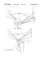
- the system of the inventionis shown in FIG. 8 . It comprises a beam generator 20 which produces two laser beams of visible laser light at precisely 90° to each other and in a plane parallel to the floor on which the unit is resting.
- a beam generator 20which produces two laser beams of visible laser light at precisely 90° to each other and in a plane parallel to the floor on which the unit is resting.
- Such beam generatorsare described in U.S. Pat. No. 5,617,202 and U.S. Pat. No. 5,500,524, belonging to the same assignee as this application, and incorporated by reference herein.
- the point of intersection of the two beamsis indicated for positioning or marking.
- a cylinder lens in the path of each beamis used to direct the beams onto the floor by the operator for the purpose of positioning the beam on a target area.
- the axis of the cylinder lensis in a plane parallel to the floor plane in order to produce a fan beam perpendicular to the floor.
- the focal lengths of the lensesare chosen to spread the beam a minimal amount to place the light where it is needed thus producing the maximum visibility for the laser power available. For example, a focal length in the range of 60 mm works well with a laser diode collimated with a 10 mm focal length, providing a beam of appropriate height.
- the beam from the lasermay be only collimated on one axis, to provide a beam which does not diverge horizontally. The natural spread of the beam in the generally vertical direction then combines with the effect of the cylinder lens, which can be less strong in this case.
- a third lens and beammay be used to project three reference lines.
- the deviceallows for up/down adjustment of each lens to concentrate the beams and resulting lines where needed.
- the light beam generator 20produces two collimated beams of light at precisely 90° to each other.
- a base plate or housing or platform 22supports the light beam generator 20 in secure and fixed position. The base plate preferably rests directly on the floor and thus provides the reference surface for the apparatus.
- a fixed vertical slide mount 24supports an adjustable slider 26 which holds a cylinder lens 28 .
- the slide mount 24preferably is an extension of the platform or housing 22 , molded of plastic material as part of the platform.
- a collimated beam of visible light 30passes through the cylinder lens 28 and forms a narrow generally vertical fan beam 32 which can be directed onto the floor as desired by moving the slider 26 up and down.
- the cylinder lenscan be slid out of the way completely, preferably in the up direction, allowing a collimated beam of light to be projected parallel to the floor when needed. Such a concentrated beam of light would be the most visible.
- a reference mark 34 on the base plate 22provides a means for marking the floor under the beam 30 , or for aligning the tool with a mark on the floor or elsewhere.
- FIGS. 9 and 10show a cross section through one slider 26 .
- the slideris moved down, steering the beam to the floor.
- the slider motionallows the operator to steer the beam along the floor, to a wall or to the ceiling.
- the slidermay also be moved out of the way to produce a beam of maximum visibility.
- the slider 26fits tightly and securely on the slide mount 24 to establish constant orientation of the lens as the slider is moved up and down. This is achieved preferably by use of a small leaf spring (not shown) acting between the slider and the outer edge of the slide mount, at one side of each slider.
- FIG. 11shows the cylinder lenses and their relation to the floor 38 .
- a light beam generator 40produces three beams of light 42 , 44 , and 46 , each at 90° to the adjacent beam.
- a coordinate system with the floor 38 in the xy planeis shown in FIG. 11 .
- the axes of the lensesmust be in a plane parallel to the xy plane, i.e. the floor. Those axes should also be perpendicular to the incoming beam to provide a symmetrical beam.
- the slider 26 of FIG. 8ensures the correct orientation of each lens as it moves on the slider.
Landscapes
- Physics & Mathematics (AREA)
- Engineering & Computer Science (AREA)
- General Physics & Mathematics (AREA)
- Radar, Positioning & Navigation (AREA)
- Remote Sensing (AREA)
- Conveying And Assembling Of Building Elements In Situ (AREA)
Abstract
Description
This invention relates to hand tools, and in particular the invention is concerned with a hand tool for projecting two or more reference beams of visible light for precise alignment on floors.
For some time laser beams have been used in construction for level reference, vertical references and layout on floors. The subject invention pertains to the last application, floor layout. It allows the user to project visible lines on the floor at precise angles for the purpose of marking the floor or to direct positions of objects or installations on the floor. Typically a construction worker marks the floor indicating the location of walls or other building elements to be constructed. In a like manner a tile layer marks the floor with reference lines. This is often done using a tape measure and a 3-4-5 triangle as shown in FIG. 1 of the drawings. This method is inaccurate and often requires two men. In an alternate method a transit equipped with a calibrated turntable is often used as shown in FIG.2. In this case the operator sets the tripod over the first point with the aid of a plumb bob. Then the telescope of the transit is used to sight a known second point and the turntable angle is noted. Subsequently the turntable is turned to the required angle and the needed third point is marked by a second person communicating with the transit operator. This method can be very accurate but requires two men and is time consuming.
Many existing methods use small battery operated lasers to aid in the job of construction layout. For example, laying out 90° reference lines can be done using a visible laser beam generator such as the LeveLite manufactured by the assignee of this application. With that tool on its side, the self-leveling feature of the tool is disabled and visible light beams at 90° to each other can be used to project two lines at 90° to each other. FIG. 3 shows such a LeveLitetool 2 on anadjustable trivet 8. Thelight beams floor using knobs 10. The floor is subsequently marked for later use. In this case the lines are relatively short and difficult to position. To make the line on the floor longer a cylinder lens may be used as is shown in FIG. 4 depicting a system of U.S. Pat. No. 5,864,956. In this case a number of individual units project individual fan beams, with the beams fixed in their orientation to each base. The operator is unable to move the fan beam to position it on the floor where it is needed. Because the blocks are fastened together, tipping one axis to move the fan beam up or down causes the fan beam at 90° to rotate causing it to be no longer vertical.
In U.S. Pat. No. 5,539,990, as shown in FIG. 5, a self-leveling platform with two fan beams at 90° to each other is used. It uses aweight 11 and a bearing not shown to level theplatform 13. In this case the beam location is not controlled by the operator and, therefore, a wide beam must be used spreading the light over a wide angle making it difficult to see.
Rotating lasers with a special transmitting penta prism are often used in this application, as shown in FIG.6. In this case the rotating laser beam is visible on the floor or may be detected using a handheld detector. A portion of the beam is transmitted through the penta prism providing a 90° reference. This technique is expensive and it is difficult to see the beam because the light is spread over 360°.
An instrument using two rotating lasers is described in U.S. Pat. No. 5,218,770 and shown in FIG.7. Again, the laser beams from this unit are difficult to see because the light is spread over a large area. In U.S. Pat. No. 5,218,770 two planes of light at 90° to each other are generated using a mirrored cone and two mirrors. The beams are so weak in this case that a special detector must be used to find the beam and in addition, two men may be required.
The subject invention is designed to overcome the limitations of the prior art by making the light-generated reference lines more visible and also adjustable as to height of projection, allowing layout by a single operator.
FIGS. 1-7 show various systems and devices according to the prior art for laying out two lines at 90° to each other. Some of these involve laser beams.
FIG. 8 shows, somewhat schematically, a device and system according to the invention.
FIGS. 9 and 10 schematically show the device of the invention in elevation, partially in section, with an adjustable beam steering lens in different positions.
FIG. 11 is a schematic perspective view illustrating a three-lens system according to the invention.
The system of the invention is shown in FIG.8. It comprises abeam generator 20 which produces two laser beams of visible laser light at precisely 90° to each other and in a plane parallel to the floor on which the unit is resting. Such beam generators are described in U.S. Pat. No. 5,617,202 and U.S. Pat. No. 5,500,524, belonging to the same assignee as this application, and incorporated by reference herein. The point of intersection of the two beams is indicated for positioning or marking. A cylinder lens in the path of each beam is used to direct the beams onto the floor by the operator for the purpose of positioning the beam on a target area. The axis of the cylinder lens is in a plane parallel to the floor plane in order to produce a fan beam perpendicular to the floor. The focal lengths of the lenses are chosen to spread the beam a minimal amount to place the light where it is needed thus producing the maximum visibility for the laser power available. For example, a focal length in the range of 60 mm works well with a laser diode collimated with a 10 mm focal length, providing a beam of appropriate height. However, the beam from the laser may be only collimated on one axis, to provide a beam which does not diverge horizontally. The natural spread of the beam in the generally vertical direction then combines with the effect of the cylinder lens, which can be less strong in this case.
A third lens and beam may be used to project three reference lines. The device allows for up/down adjustment of each lens to concentrate the beams and resulting lines where needed.
In FIG. 8 thelight beam generator 20 produces two collimated beams of light at precisely 90° to each other. A base plate or housing orplatform 22 supports thelight beam generator 20 in secure and fixed position. The base plate preferably rests directly on the floor and thus provides the reference surface for the apparatus. A fixedvertical slide mount 24 supports anadjustable slider 26 which holds acylinder lens 28. The slide mount24 preferably is an extension of the platform orhousing 22, molded of plastic material as part of the platform. A collimated beam of visible light30 passes through thecylinder lens 28 and forms a narrow generallyvertical fan beam 32 which can be directed onto the floor as desired by moving theslider 26 up and down. In addition the cylinder lens can be slid out of the way completely, preferably in the up direction, allowing a collimated beam of light to be projected parallel to the floor when needed. Such a concentrated beam of light would be the most visible. Areference mark 34 on thebase plate 22 provides a means for marking the floor under thebeam 30, or for aligning the tool with a mark on the floor or elsewhere.
Features identical to the features24-34 are located on thebase plate 22 at 90° from thefirst light beam 30, for asecond beam 30a, as shown in FIG.8. The two reference marks34 on the tool locate the intersection of the two beams.
FIGS. 9 and 10 show a cross section through oneslider 26. In FIG. 10 the slider is moved down, steering the beam to the floor. The slider motion allows the operator to steer the beam along the floor, to a wall or to the ceiling. The slider may also be moved out of the way to produce a beam of maximum visibility.
Theslider 26 fits tightly and securely on theslide mount 24 to establish constant orientation of the lens as the slider is moved up and down. This is achieved preferably by use of a small leaf spring (not shown) acting between the slider and the outer edge of the slide mount, at one side of each slider.
FIG. 11 shows the cylinder lenses and their relation to thefloor 38. Alight beam generator 40 produces three beams oflight floor 38 in the xy plane is shown in FIG.11. To ensure that the fan beams generated bycylinder lenses slider 26 of FIG. 8 ensures the correct orientation of each lens as it moves on the slider.
The above described preferred embodiments are intended to illustrate the principles of the invention, but not to limit its scope. Other embodiments and variations to this preferred embodiment will be apparent to those skilled in the art and may be made without departing from the spirit and scope of the invention.
Claims (10)
1. A device for layout of objects or installations on a floor or other generally horizontal surface, along two angularly related lines on the floor or surface, comprising:
a platform or housing having a reference surface with means for holding the platform or housing in a position with the reference surface substantially parallel to the floor or other surface,
a light beam generator producing at least two beams of visible light at a desired angle relative to one another, the beams being collimated at least in one axis and the beams being generally parallel to the reference surface,
cylinder lens means in the path of at least one of the two beams, for spreading the beam into a fan of light essentially perpendicular to the reference surface,
adjustment means connected to the cylinder lens means, for enabling manual adjustment of the cylinder lens means up or down relative to the reference surface, so as to enable steering of the fan of light to direct it higher or lower, so as to form lines on the floor or other generally horizontal surface or on one or more adjacent walls or vertical surfaces, and
means on the platform or housing for marking or sighting on the floor the intersection of the two beams and of the two fans of light.
2. The device of claim1, wherein said desired angle between the two beams of light is 90°.
3. The device of claim1, wherein the cylinder lens means comprises a cylindrical lens, having an axis lying in a plane which is parallel to said reference surface.
4. The device of claim1, including said cylinder lens means in the path of each of the beams of light.
5. The device of claim4, including said adjustment means on each cylinder lens means.
6. The device of claim1, wherein said means for holding the platform or housing comprises said reference surface being a bottom surface of the platform or housing, for placement directly on the floor or other generally horizontal surface.
7. The device of claim1, wherein at least three beams are projected from the light beam generator, each at 90° relative to an adjacent one of the beams.
8. The device of claim7, wherein the device includes a cylinder lens means in the path of each beam.
9. The device of claim1 wherein the two beams of visible light are each fully collimated.
10. The device of claim1, wherein the adjustment means comprises an integrally molded plastic slide mount extending generally vertically up from the platform or housing adjacent to the light beam, and a slider mounted stably on the slide mount for generally vertical sliding adjustment, with a cylinder lens fixed to the slider.
Priority Applications (1)
| Application Number | Priority Date | Filing Date | Title |
|---|---|---|---|
| US09/264,371US6202312B1 (en) | 1999-03-08 | 1999-03-08 | Laser tool for generating perpendicular lines of light on floor |
Applications Claiming Priority (1)
| Application Number | Priority Date | Filing Date | Title |
|---|---|---|---|
| US09/264,371US6202312B1 (en) | 1999-03-08 | 1999-03-08 | Laser tool for generating perpendicular lines of light on floor |
Publications (1)
| Publication Number | Publication Date |
|---|---|
| US6202312B1true US6202312B1 (en) | 2001-03-20 |
Family
ID=23005762
Family Applications (1)
| Application Number | Title | Priority Date | Filing Date |
|---|---|---|---|
| US09/264,371Expired - LifetimeUS6202312B1 (en) | 1999-03-08 | 1999-03-08 | Laser tool for generating perpendicular lines of light on floor |
Country Status (1)
| Country | Link |
|---|---|
| US (1) | US6202312B1 (en) |
Cited By (79)
| Publication number | Priority date | Publication date | Assignee | Title |
|---|---|---|---|---|
| US6279239B1 (en)* | 1999-04-19 | 2001-08-28 | Edward Astudillo | Device and a method for sizing odd parts of drywall for placement on ceilings and walls |
| US6314651B1 (en)* | 1998-12-03 | 2001-11-13 | Kabushiki Kaisha Topcon | Rotary laser irradiating system and photodetection system |
| US6397448B1 (en)* | 2000-09-19 | 2002-06-04 | Meritor Heavy Vehicle Technology, Llc | Method of mounting aligned suspension assemblies for heavy-duty trailers |
| US6487783B1 (en) | 2001-05-24 | 2002-12-03 | Thomas A. Thomas, Jr. | Laser guided chalk line apparatus |
| US6502319B1 (en)* | 2000-10-04 | 2003-01-07 | Levelite Technology, Inc. | Apparatus for producing a visible line of light on a surface |
| US20030029048A1 (en)* | 2001-08-10 | 2003-02-13 | Chao-Chi Huang | Laser projection apparatus for point and line |
| US6578274B1 (en)* | 2000-02-25 | 2003-06-17 | Ronald M. Tango, Jr. | Construction layout block |
| US20030231303A1 (en)* | 2002-05-31 | 2003-12-18 | Raskin James R. | Laser level |
| US6694629B2 (en) | 2002-02-27 | 2004-02-24 | Trimble Navigation Llc | Laser projector for producing intersecting lines on a surface |
| US6735879B2 (en)* | 2001-05-15 | 2004-05-18 | Irwin Industrial Tool Company | Laser line generating device |
| US20040103546A1 (en)* | 2002-05-31 | 2004-06-03 | Marshall James D. | Laser level |
| US20040111898A1 (en)* | 2002-05-31 | 2004-06-17 | Marshall James D. | Laser level |
| US6793831B1 (en)* | 1998-08-06 | 2004-09-21 | State Of Oregon Acting By And Through The State Board Of Higher Education On Behalf Of Oregon State University | Microlamination method for making devices |
| USD499030S1 (en) | 2004-03-15 | 2004-11-30 | David L. Searls | Combined chalk line and laser device |
| US20040258126A1 (en)* | 2003-06-18 | 2004-12-23 | Levine Steven R. | Laser line generating device with swivel base |
| US20050005462A1 (en)* | 2003-07-11 | 2005-01-13 | Zircon Corporation | Modular laser layout system |
| US20050044735A1 (en)* | 2003-08-29 | 2005-03-03 | Vincent Liao | Laser leveling device having selectable light beam |
| US6912792B1 (en)* | 2003-11-03 | 2005-07-05 | Uthman T. Shareef | Apparatus for determining a level surface |
| US20050150126A1 (en)* | 2004-01-12 | 2005-07-14 | Marshall James D. | Tape measure with laser beam |
| US20050155238A1 (en)* | 2003-07-01 | 2005-07-21 | Levine Steven R. | Laser line generating device with swivel base |
| EP1476318A4 (en)* | 2002-02-01 | 2005-08-31 | Trimble Navigation Ltd | Apparatus for producing a visible line of light on a surface |
| US20050198845A1 (en)* | 2004-02-19 | 2005-09-15 | Glenn Robinson | Multiple laser laser level |
| US20050274030A1 (en)* | 2001-05-15 | 2005-12-15 | Spanski Jeffrey L | Laser line generating device with graduated base |
| US20050278966A1 (en)* | 2004-06-18 | 2005-12-22 | Liu Carl Y | Laser level |
| US20050283987A1 (en)* | 2004-06-25 | 2005-12-29 | Irwin Industrial Tool Company | Laser line projected on an edge of a surface |
| US20060013278A1 (en)* | 2002-10-22 | 2006-01-19 | Raskin James R | Laser level |
| US20060017427A1 (en)* | 2004-07-21 | 2006-01-26 | Nash Derek J | Intersecting laser line generating device |
| US20060021237A1 (en)* | 2002-05-31 | 2006-02-02 | Marshall James D | Measuring and leveling device |
| US20060037202A1 (en)* | 2004-08-17 | 2006-02-23 | Long Charles K | Laser leveling device having a suction mounting arrangement |
| US20060037203A1 (en)* | 2004-08-17 | 2006-02-23 | Long Charles K | Modular tool assembly having a vacuum mounting arrangement |
| US7013570B2 (en) | 2003-06-18 | 2006-03-21 | Irwin-Industrial Tool Company | Stud finder |
| US7055252B2 (en) | 2002-12-27 | 2006-06-06 | Chervon International Trading Co., Ltd. | Laser level with adjustable laser projection line |
| US7065890B1 (en) | 2005-01-31 | 2006-06-27 | Shu Chen Chang | Adjustable support device for level facility |
| US20060196059A1 (en)* | 2005-03-04 | 2006-09-07 | Joseph Berto | Device for graphically showing a schedule |
| EP1722192A2 (en) | 2005-05-12 | 2006-11-15 | HILTI Aktiengesellschaft | Easy to use area coordinate measuring device |
| WO2006125463A1 (en)* | 2005-05-27 | 2006-11-30 | I-Concepts & Marketing Sarl | Electronic squaring tool |
| US20070006471A1 (en)* | 2005-07-07 | 2007-01-11 | Van Trump Gary N | Light-emitting depth cut gauge |
| US20070028470A1 (en)* | 2005-08-04 | 2007-02-08 | Nash Derek J | Laser reference device |
| US20070028469A1 (en)* | 2005-08-05 | 2007-02-08 | Nash Derek J | Laser level |
| US20070044332A1 (en)* | 2005-08-26 | 2007-03-01 | Billy Yung | Laser leveler with rotatable top section |
| US20070044331A1 (en)* | 2005-08-26 | 2007-03-01 | Billy Yung | Laser leveler with ultrasonic transmitter and receiver |
| EP1760428A1 (en) | 2005-09-06 | 2007-03-07 | Leica Geosystems AG | Reference beam generator and system for generating guiding beams for marking trolleys |
| US20070056173A1 (en)* | 2005-09-12 | 2007-03-15 | Burry James M | Laser reference device |
| US20070184576A1 (en)* | 2005-11-29 | 2007-08-09 | Oregon State University | Solution deposition of inorganic materials and electronic devices made comprising the inorganic materials |
| US20080062669A1 (en)* | 2006-09-07 | 2008-03-13 | Parel Thomas M | Gravity dial level indicator for line generator |
| US20080078091A1 (en)* | 2006-09-28 | 2008-04-03 | Mccracken Robert E | Self-leveling mechanism |
| US20080108122A1 (en)* | 2006-09-01 | 2008-05-08 | State of Oregon acting by and through the State Board of Higher Education on behalf of Oregon | Microchemical nanofactories |
| US20080174761A1 (en)* | 2007-01-19 | 2008-07-24 | Chevron Limited | Laser distance finder |
| US20080174760A1 (en)* | 2007-01-19 | 2008-07-24 | Chervon Limited | Laser distance finder |
| US20080301955A1 (en)* | 2006-11-24 | 2008-12-11 | Wolfgang Scheyer | Cross laser device for installation of plate-shaped or board-shaped floor covering elements |
| US7493701B2 (en) | 2006-05-26 | 2009-02-24 | Chevron Limited | Self-leveling laser apparatus and a method for controlling the same |
| US20090056153A1 (en)* | 2007-09-05 | 2009-03-05 | Musco Corporation | Apparatus, method, and system of precise identification of multiple points distributed throughout an area |
| US20090211977A1 (en)* | 2008-02-27 | 2009-08-27 | Oregon State University | Through-plate microchannel transfer devices |
| US20090277315A1 (en)* | 2008-05-08 | 2009-11-12 | Alek Ipatenco | Tile saw |
| WO2009135548A1 (en)* | 2008-05-07 | 2009-11-12 | Robert Bosch Gmbh | Marking device and marking method |
| USD605538S1 (en) | 2007-01-04 | 2009-12-08 | Sola-Messwerkzeuge Gmbh | Floor cross laser measuring instrument |
| US20090320302A1 (en)* | 2008-06-25 | 2009-12-31 | William Boyd | Square foot alignment device |
| US20100326916A1 (en)* | 2009-06-24 | 2010-12-30 | State of Oregon acting by and through the State Board of Higher Education on behalf of Oregon | Dialysis system |
| US20100326914A1 (en)* | 2009-06-24 | 2010-12-30 | State of Oregon acting by and through the State Board of Higher Education on behalf of Oregon | Microfluidic devices |
| US7955504B1 (en) | 2004-10-06 | 2011-06-07 | State Of Oregon Acting By And Through The State Board Of Higher Education On Behalf Of Oregon State University | Microfluidic devices, particularly filtration devices comprising polymeric membranes, and method for their manufacture and use |
| US20110189048A1 (en)* | 2009-12-05 | 2011-08-04 | Curtis James R | Modular dialysis system |
| US8236599B2 (en) | 2009-04-09 | 2012-08-07 | State of Oregon acting by and through the State Board of Higher Education | Solution-based process for making inorganic materials |
| US8501009B2 (en) | 2010-06-07 | 2013-08-06 | State Of Oregon Acting By And Through The State Board Of Higher Education On Behalf Of Oregon State University | Fluid purification system |
| JP2013152224A (en)* | 2011-12-23 | 2013-08-08 | Hilti Ag | Optical system |
| US8580161B2 (en) | 2010-05-04 | 2013-11-12 | State Of Oregon Acting By And Through The State Board Of Higher Education On Behalf Of Oregon State University | Fluidic devices comprising photocontrollable units |
| US9328969B2 (en) | 2011-10-07 | 2016-05-03 | Outset Medical, Inc. | Heat exchange fluid purification for dialysis system |
| US9402945B2 (en) | 2014-04-29 | 2016-08-02 | Outset Medical, Inc. | Dialysis system and methods |
| US9441951B1 (en)* | 2013-11-25 | 2016-09-13 | Amazon Technologies, Inc. | Documenting test room configurations |
| US9441967B2 (en) | 2013-05-31 | 2016-09-13 | Stanley Black & Decker Inc. | Laser level system |
| US20160282114A1 (en)* | 2015-03-23 | 2016-09-29 | Walter Wells Rice | Combination Level and Right Angle Measuring Tool |
| US9518823B2 (en) | 2014-01-23 | 2016-12-13 | Jayson Hill | Adjustable laser leveling device and method |
| US9545469B2 (en) | 2009-12-05 | 2017-01-17 | Outset Medical, Inc. | Dialysis system with ultrafiltration control |
| US20170122735A1 (en)* | 2014-06-15 | 2017-05-04 | Cct Creative Construction Tools Ltd. | Method and apparatus for assisting in tiling |
| US9846034B2 (en) | 2014-01-23 | 2017-12-19 | Sure Hang, Llc | Adjustable laser leveling device with distance measuring lasers and self-leveling lasers and related method |
| US11534537B2 (en) | 2016-08-19 | 2022-12-27 | Outset Medical, Inc. | Peritoneal dialysis system and methods |
| US20240369360A1 (en)* | 2023-05-04 | 2024-11-07 | Bryan Almodovar | Laser measuring stakeout device |
| US12201762B2 (en) | 2018-08-23 | 2025-01-21 | Outset Medical, Inc. | Dialysis system and methods |
| US12390565B2 (en) | 2019-04-30 | 2025-08-19 | Outset Medical, Inc. | Dialysis systems and methods |
| US12422257B1 (en)* | 2023-03-15 | 2025-09-23 | Amazon Technologies, Inc. | Fiducial alignment device |
Citations (9)
| Publication number | Priority date | Publication date | Assignee | Title |
|---|---|---|---|---|
| US5144487A (en)* | 1991-09-03 | 1992-09-01 | Pacific Laser | Portable laser device for alignment tasks |
| US5218770A (en) | 1990-11-27 | 1993-06-15 | Asahi Seimitsu Kabushiki Kaisha | Surveying machine for construction work |
| US5500524A (en) | 1994-09-23 | 1996-03-19 | Levelite Technology, Inc. | Diode laser co-linear light beam generator |
| US5539990A (en)* | 1995-05-30 | 1996-07-30 | Le; Mike | Three-dimensional optical levelling, plumbing and angle-calibrating instrument |
| US5617202A (en) | 1994-05-24 | 1997-04-01 | Levelite Technology, Inc. | Diode laser co-linear and intersecting light beam generator |
| US5782003A (en)* | 1995-02-22 | 1998-07-21 | Bozzo; Mario Doriguzzi | Device for projecting a flat beam of diverging laser rays |
| US5864956A (en) | 1996-11-22 | 1999-02-02 | Dong; Dawei | Level line and limb line combination |
| US5872657A (en)* | 1996-05-31 | 1999-02-16 | Levelite Technology, Inc. | Construction laser accessory for generating aligned spots |
| US5983510A (en)* | 1997-08-26 | 1999-11-16 | Wu; Chyi-Yiing | Three-dimensional laser levelling and angle-calibrating instrument with multiple functions |
- 1999
- 1999-03-08USUS09/264,371patent/US6202312B1/ennot_activeExpired - Lifetime
Patent Citations (9)
| Publication number | Priority date | Publication date | Assignee | Title |
|---|---|---|---|---|
| US5218770A (en) | 1990-11-27 | 1993-06-15 | Asahi Seimitsu Kabushiki Kaisha | Surveying machine for construction work |
| US5144487A (en)* | 1991-09-03 | 1992-09-01 | Pacific Laser | Portable laser device for alignment tasks |
| US5617202A (en) | 1994-05-24 | 1997-04-01 | Levelite Technology, Inc. | Diode laser co-linear and intersecting light beam generator |
| US5500524A (en) | 1994-09-23 | 1996-03-19 | Levelite Technology, Inc. | Diode laser co-linear light beam generator |
| US5782003A (en)* | 1995-02-22 | 1998-07-21 | Bozzo; Mario Doriguzzi | Device for projecting a flat beam of diverging laser rays |
| US5539990A (en)* | 1995-05-30 | 1996-07-30 | Le; Mike | Three-dimensional optical levelling, plumbing and angle-calibrating instrument |
| US5872657A (en)* | 1996-05-31 | 1999-02-16 | Levelite Technology, Inc. | Construction laser accessory for generating aligned spots |
| US5864956A (en) | 1996-11-22 | 1999-02-02 | Dong; Dawei | Level line and limb line combination |
| US5983510A (en)* | 1997-08-26 | 1999-11-16 | Wu; Chyi-Yiing | Three-dimensional laser levelling and angle-calibrating instrument with multiple functions |
Non-Patent Citations (1)
| Title |
|---|
| "BMI Laser-Technic"Catalog Hersbuck, Germany, Dec. 1995. |
Cited By (137)
| Publication number | Priority date | Publication date | Assignee | Title |
|---|---|---|---|---|
| US6793831B1 (en)* | 1998-08-06 | 2004-09-21 | State Of Oregon Acting By And Through The State Board Of Higher Education On Behalf Of Oregon State University | Microlamination method for making devices |
| US6314651B1 (en)* | 1998-12-03 | 2001-11-13 | Kabushiki Kaisha Topcon | Rotary laser irradiating system and photodetection system |
| US6279239B1 (en)* | 1999-04-19 | 2001-08-28 | Edward Astudillo | Device and a method for sizing odd parts of drywall for placement on ceilings and walls |
| US6578274B1 (en)* | 2000-02-25 | 2003-06-17 | Ronald M. Tango, Jr. | Construction layout block |
| US6397448B1 (en)* | 2000-09-19 | 2002-06-04 | Meritor Heavy Vehicle Technology, Llc | Method of mounting aligned suspension assemblies for heavy-duty trailers |
| US6502319B1 (en)* | 2000-10-04 | 2003-01-07 | Levelite Technology, Inc. | Apparatus for producing a visible line of light on a surface |
| WO2003066349A1 (en)* | 2000-10-04 | 2003-08-14 | Trimble Navigation Limited | Apparatus for producing a visible line of light on a surface |
| US7513051B2 (en) | 2001-05-15 | 2009-04-07 | Irwin Industrial Tool Company | Laser line generating device with graduated base |
| US20050274030A1 (en)* | 2001-05-15 | 2005-12-15 | Spanski Jeffrey L | Laser line generating device with graduated base |
| US6735879B2 (en)* | 2001-05-15 | 2004-05-18 | Irwin Industrial Tool Company | Laser line generating device |
| US6487783B1 (en) | 2001-05-24 | 2002-12-03 | Thomas A. Thomas, Jr. | Laser guided chalk line apparatus |
| US6722048B2 (en)* | 2001-08-10 | 2004-04-20 | Quarton, Inc. | Laser projection apparatus for point and line |
| US20030029048A1 (en)* | 2001-08-10 | 2003-02-13 | Chao-Chi Huang | Laser projection apparatus for point and line |
| EP1476318A4 (en)* | 2002-02-01 | 2005-08-31 | Trimble Navigation Ltd | Apparatus for producing a visible line of light on a surface |
| US6694629B2 (en) | 2002-02-27 | 2004-02-24 | Trimble Navigation Llc | Laser projector for producing intersecting lines on a surface |
| US20040083614A1 (en)* | 2002-05-31 | 2004-05-06 | Raskin James R. | Laser level |
| US7031367B2 (en)* | 2002-05-31 | 2006-04-18 | Black & Decker Inc. | Laser level |
| US20030231303A1 (en)* | 2002-05-31 | 2003-12-18 | Raskin James R. | Laser level |
| US7134212B2 (en) | 2002-05-31 | 2006-11-14 | Black & Decker Inc. | Laser level |
| US7027480B2 (en)* | 2002-05-31 | 2006-04-11 | Black & Decker Inc. | Laser level |
| US20060159153A1 (en)* | 2002-05-31 | 2006-07-20 | Marshall James D | Laser level |
| US6914930B2 (en) | 2002-05-31 | 2005-07-05 | Black & Decker Inc. | Laser level |
| US7059057B2 (en)* | 2002-05-31 | 2006-06-13 | Black & Decker Inc. | Laser level |
| US20040103546A1 (en)* | 2002-05-31 | 2004-06-03 | Marshall James D. | Laser level |
| US20040111898A1 (en)* | 2002-05-31 | 2004-06-17 | Marshall James D. | Laser level |
| US20060021237A1 (en)* | 2002-05-31 | 2006-02-02 | Marshall James D | Measuring and leveling device |
| US20060013278A1 (en)* | 2002-10-22 | 2006-01-19 | Raskin James R | Laser level |
| US7055252B2 (en) | 2002-12-27 | 2006-06-06 | Chervon International Trading Co., Ltd. | Laser level with adjustable laser projection line |
| US7278218B2 (en) | 2003-06-18 | 2007-10-09 | Irwin Industrial Tool Company | Laser line generating device with swivel base |
| US7013570B2 (en) | 2003-06-18 | 2006-03-21 | Irwin-Industrial Tool Company | Stud finder |
| US20040258126A1 (en)* | 2003-06-18 | 2004-12-23 | Levine Steven R. | Laser line generating device with swivel base |
| US20050155238A1 (en)* | 2003-07-01 | 2005-07-21 | Levine Steven R. | Laser line generating device with swivel base |
| US7269907B2 (en) | 2003-07-01 | 2007-09-18 | Irwin Industrial Tool Company | Laser line generating device with swivel base |
| US7181853B2 (en) | 2003-07-11 | 2007-02-27 | Zircon Corporation | Modular laser layout system |
| US20050005462A1 (en)* | 2003-07-11 | 2005-01-13 | Zircon Corporation | Modular laser layout system |
| US20050044735A1 (en)* | 2003-08-29 | 2005-03-03 | Vincent Liao | Laser leveling device having selectable light beam |
| US6912792B1 (en)* | 2003-11-03 | 2005-07-05 | Uthman T. Shareef | Apparatus for determining a level surface |
| US7024791B2 (en)* | 2004-01-12 | 2006-04-11 | Black & Decker Inc. | Tape measure with laser beam |
| US20050150126A1 (en)* | 2004-01-12 | 2005-07-14 | Marshall James D. | Tape measure with laser beam |
| US7299565B2 (en) | 2004-01-12 | 2007-11-27 | Black & Decker | Tape measure |
| US20060248742A1 (en)* | 2004-01-12 | 2006-11-09 | Marshall James D | Tape measure |
| US20050198845A1 (en)* | 2004-02-19 | 2005-09-15 | Glenn Robinson | Multiple laser laser level |
| USD499030S1 (en) | 2004-03-15 | 2004-11-30 | David L. Searls | Combined chalk line and laser device |
| US20050278966A1 (en)* | 2004-06-18 | 2005-12-22 | Liu Carl Y | Laser level |
| US7487596B2 (en) | 2004-06-25 | 2009-02-10 | Irwin Industrial Tool Company | Laser line projected on an edge of a surface |
| US20050283987A1 (en)* | 2004-06-25 | 2005-12-29 | Irwin Industrial Tool Company | Laser line projected on an edge of a surface |
| US7310887B2 (en)* | 2004-07-21 | 2007-12-25 | Irwin Industrial Tool Company | Intersecting laser line generating device |
| US7178250B2 (en) | 2004-07-21 | 2007-02-20 | Irwin Industrial Tool Company | Intersecting laser line generating device |
| US7469481B2 (en) | 2004-07-21 | 2008-12-30 | Irwin Industrial Tool Company | Intersecting laser line generating device |
| US20080083125A1 (en)* | 2004-07-21 | 2008-04-10 | Nash Derek J | Intersecting Laser Line Generating Device |
| US20070124948A1 (en)* | 2004-07-21 | 2007-06-07 | Nash Derek J | Intersecting laser line generating device |
| US20060017427A1 (en)* | 2004-07-21 | 2006-01-26 | Nash Derek J | Intersecting laser line generating device |
| US7181854B2 (en) | 2004-08-17 | 2007-02-27 | Eastway Fair Company Limited | Laser leveling device having a suction mounting arrangement |
| US7191532B2 (en) | 2004-08-17 | 2007-03-20 | Eastway Fair Company Limited | Modular tool assembly having a vacuum mounting arrangement |
| US20060037202A1 (en)* | 2004-08-17 | 2006-02-23 | Long Charles K | Laser leveling device having a suction mounting arrangement |
| US7322116B2 (en) | 2004-08-17 | 2008-01-29 | Eastway Fair Company Limited | Laser leveling device having a suction mounting arrangement |
| US20060037203A1 (en)* | 2004-08-17 | 2006-02-23 | Long Charles K | Modular tool assembly having a vacuum mounting arrangement |
| US20060185181A1 (en)* | 2004-08-17 | 2006-08-24 | Long Charles K | Structure mountable assembly |
| US7260895B2 (en) | 2004-08-17 | 2007-08-28 | Eastway Fair Company | Structure mountable assembly |
| US7174648B2 (en) | 2004-08-17 | 2007-02-13 | Eastway Fair Company | Structure mountable assembly |
| US8137554B2 (en) | 2004-10-06 | 2012-03-20 | State Of Oregon Acting By And Through The State Board Of Higher Education On Behalf Of Oregon State University | Microfluidic devices, particularly filtration devices comprising polymeric membranes, and method for their manufacture and use |
| US8273245B2 (en) | 2004-10-06 | 2012-09-25 | State Of Oregon Acting By And Through The State Board Of Higher Education On Behalf Of Oregon State University | Microfluidic devices, particularly filtration devices comprising polymeric membranes, and methods for their manufacture and use |
| US7955504B1 (en) | 2004-10-06 | 2011-06-07 | State Of Oregon Acting By And Through The State Board Of Higher Education On Behalf Of Oregon State University | Microfluidic devices, particularly filtration devices comprising polymeric membranes, and method for their manufacture and use |
| US7065890B1 (en) | 2005-01-31 | 2006-06-27 | Shu Chen Chang | Adjustable support device for level facility |
| US20060196059A1 (en)* | 2005-03-04 | 2006-09-07 | Joseph Berto | Device for graphically showing a schedule |
| US20060259269A1 (en)* | 2005-05-12 | 2006-11-16 | Hilti Aktiengesellschaft | Handheld surface coordinate measuring device |
| EP1722192A2 (en) | 2005-05-12 | 2006-11-15 | HILTI Aktiengesellschaft | Easy to use area coordinate measuring device |
| US7426451B2 (en) | 2005-05-12 | 2008-09-16 | Hilti Aktiengesellschaft | Handheld surface coordinate measuring device |
| WO2006125463A1 (en)* | 2005-05-27 | 2006-11-30 | I-Concepts & Marketing Sarl | Electronic squaring tool |
| US20070006471A1 (en)* | 2005-07-07 | 2007-01-11 | Van Trump Gary N | Light-emitting depth cut gauge |
| US7497019B2 (en) | 2005-08-04 | 2009-03-03 | Irwin Industrial Tool Company | Laser reference device |
| US20070028470A1 (en)* | 2005-08-04 | 2007-02-08 | Nash Derek J | Laser reference device |
| US20070028469A1 (en)* | 2005-08-05 | 2007-02-08 | Nash Derek J | Laser level |
| US7328516B2 (en) | 2005-08-05 | 2008-02-12 | Irwin Industrial Tool Company | Laser level |
| US20070044331A1 (en)* | 2005-08-26 | 2007-03-01 | Billy Yung | Laser leveler with ultrasonic transmitter and receiver |
| US20070044332A1 (en)* | 2005-08-26 | 2007-03-01 | Billy Yung | Laser leveler with rotatable top section |
| EP1760428A1 (en) | 2005-09-06 | 2007-03-07 | Leica Geosystems AG | Reference beam generator and system for generating guiding beams for marking trolleys |
| US20070062053A1 (en)* | 2005-09-06 | 2007-03-22 | Leica Geosystems Ag | Reference beam generator and system for producing guide beams for field markers |
| US7434322B2 (en)* | 2005-09-06 | 2008-10-14 | Leica Geosystems Ag | Reference beam generator and system for producing guide beams for field markers |
| US7377045B2 (en) | 2005-09-12 | 2008-05-27 | Irwin Industrial Tool Company | Laser reference device |
| US20080282561A1 (en)* | 2005-09-12 | 2008-11-20 | Irwin Industrial Tool Company | Laser reference device |
| US7640672B2 (en) | 2005-09-12 | 2010-01-05 | Irwin Industrial Tool Company | Laser reference device |
| US20070056173A1 (en)* | 2005-09-12 | 2007-03-15 | Burry James M | Laser reference device |
| US20070184576A1 (en)* | 2005-11-29 | 2007-08-09 | Oregon State University | Solution deposition of inorganic materials and electronic devices made comprising the inorganic materials |
| US8679587B2 (en) | 2005-11-29 | 2014-03-25 | State of Oregon acting by and through the State Board of Higher Education action on Behalf of Oregon State University | Solution deposition of inorganic materials and electronic devices made comprising the inorganic materials |
| US7493701B2 (en) | 2006-05-26 | 2009-02-24 | Chevron Limited | Self-leveling laser apparatus and a method for controlling the same |
| US20080108122A1 (en)* | 2006-09-01 | 2008-05-08 | State of Oregon acting by and through the State Board of Higher Education on behalf of Oregon | Microchemical nanofactories |
| US20080062669A1 (en)* | 2006-09-07 | 2008-03-13 | Parel Thomas M | Gravity dial level indicator for line generator |
| US7591075B2 (en) | 2006-09-28 | 2009-09-22 | Techtronic Power Tools Technology Limited | Self-leveling mechanism |
| US20080078091A1 (en)* | 2006-09-28 | 2008-04-03 | Mccracken Robert E | Self-leveling mechanism |
| US20080301955A1 (en)* | 2006-11-24 | 2008-12-11 | Wolfgang Scheyer | Cross laser device for installation of plate-shaped or board-shaped floor covering elements |
| US7676939B2 (en)* | 2006-11-24 | 2010-03-16 | Sola Immobilienverwaltungs Gmbh | Cross laser device for installation of plate-shaped or board-shaped floor covering elements |
| USD605538S1 (en) | 2007-01-04 | 2009-12-08 | Sola-Messwerkzeuge Gmbh | Floor cross laser measuring instrument |
| US7609364B2 (en) | 2007-01-19 | 2009-10-27 | Chervon Limited | Laser distance finder |
| US7554651B2 (en) | 2007-01-19 | 2009-06-30 | Chevron Limited | Laser distance finder |
| US20080174761A1 (en)* | 2007-01-19 | 2008-07-24 | Chevron Limited | Laser distance finder |
| US20080174760A1 (en)* | 2007-01-19 | 2008-07-24 | Chervon Limited | Laser distance finder |
| US20090056153A1 (en)* | 2007-09-05 | 2009-03-05 | Musco Corporation | Apparatus, method, and system of precise identification of multiple points distributed throughout an area |
| US8006394B2 (en)* | 2007-09-05 | 2011-08-30 | Musco Corporation | Apparatus, method and system of precise identification of multiple points distributed throughout an area |
| US20090211977A1 (en)* | 2008-02-27 | 2009-08-27 | Oregon State University | Through-plate microchannel transfer devices |
| WO2009135548A1 (en)* | 2008-05-07 | 2009-11-12 | Robert Bosch Gmbh | Marking device and marking method |
| US20090277315A1 (en)* | 2008-05-08 | 2009-11-12 | Alek Ipatenco | Tile saw |
| US20090320302A1 (en)* | 2008-06-25 | 2009-12-31 | William Boyd | Square foot alignment device |
| US8236599B2 (en) | 2009-04-09 | 2012-08-07 | State of Oregon acting by and through the State Board of Higher Education | Solution-based process for making inorganic materials |
| US20100326914A1 (en)* | 2009-06-24 | 2010-12-30 | State of Oregon acting by and through the State Board of Higher Education on behalf of Oregon | Microfluidic devices |
| US20100326916A1 (en)* | 2009-06-24 | 2010-12-30 | State of Oregon acting by and through the State Board of Higher Education on behalf of Oregon | Dialysis system |
| US8801922B2 (en) | 2009-06-24 | 2014-08-12 | State Of Oregon Acting By And Through The State Board Of Higher Education On Behalf Of Oregon State University | Dialysis system |
| US20110189048A1 (en)* | 2009-12-05 | 2011-08-04 | Curtis James R | Modular dialysis system |
| US9545469B2 (en) | 2009-12-05 | 2017-01-17 | Outset Medical, Inc. | Dialysis system with ultrafiltration control |
| US8580161B2 (en) | 2010-05-04 | 2013-11-12 | State Of Oregon Acting By And Through The State Board Of Higher Education On Behalf Of Oregon State University | Fluidic devices comprising photocontrollable units |
| US8501009B2 (en) | 2010-06-07 | 2013-08-06 | State Of Oregon Acting By And Through The State Board Of Higher Education On Behalf Of Oregon State University | Fluid purification system |
| US8524086B2 (en) | 2010-06-07 | 2013-09-03 | State Of Oregon Acting By And Through The State Board Of Higher Education On Behalf Of Oregon State University | Fluid purification system |
| US9138687B2 (en) | 2010-06-07 | 2015-09-22 | Oregon State University | Fluid purification system |
| US11724013B2 (en) | 2010-06-07 | 2023-08-15 | Outset Medical, Inc. | Fluid purification system |
| US10668201B2 (en) | 2010-06-07 | 2020-06-02 | Oregon State University | Dialysis system |
| US10105476B2 (en) | 2010-06-07 | 2018-10-23 | Oregon State University | Fluid purification system |
| US9895480B2 (en) | 2010-06-07 | 2018-02-20 | Oregon State University | Dialysis system |
| US9328969B2 (en) | 2011-10-07 | 2016-05-03 | Outset Medical, Inc. | Heat exchange fluid purification for dialysis system |
| JP2013152224A (en)* | 2011-12-23 | 2013-08-08 | Hilti Ag | Optical system |
| US9441967B2 (en) | 2013-05-31 | 2016-09-13 | Stanley Black & Decker Inc. | Laser level system |
| US9441951B1 (en)* | 2013-11-25 | 2016-09-13 | Amazon Technologies, Inc. | Documenting test room configurations |
| US9846034B2 (en) | 2014-01-23 | 2017-12-19 | Sure Hang, Llc | Adjustable laser leveling device with distance measuring lasers and self-leveling lasers and related method |
| US9518823B2 (en) | 2014-01-23 | 2016-12-13 | Jayson Hill | Adjustable laser leveling device and method |
| US9402945B2 (en) | 2014-04-29 | 2016-08-02 | Outset Medical, Inc. | Dialysis system and methods |
| US9504777B2 (en) | 2014-04-29 | 2016-11-29 | Outset Medical, Inc. | Dialysis system and methods |
| US11305040B2 (en) | 2014-04-29 | 2022-04-19 | Outset Medical, Inc. | Dialysis system and methods |
| US9579440B2 (en) | 2014-04-29 | 2017-02-28 | Outset Medical, Inc. | Dialysis system and methods |
| US20170122735A1 (en)* | 2014-06-15 | 2017-05-04 | Cct Creative Construction Tools Ltd. | Method and apparatus for assisting in tiling |
| US10488197B2 (en)* | 2014-06-15 | 2019-11-26 | Cct Creative Construction Tools Ltd. | Method and apparatus for assisting in tiling |
| US9778034B2 (en)* | 2015-03-23 | 2017-10-03 | Walter Wells Rice | Combination level and right angle measuring tool |
| US20160282114A1 (en)* | 2015-03-23 | 2016-09-29 | Walter Wells Rice | Combination Level and Right Angle Measuring Tool |
| US11534537B2 (en) | 2016-08-19 | 2022-12-27 | Outset Medical, Inc. | Peritoneal dialysis system and methods |
| US11951241B2 (en) | 2016-08-19 | 2024-04-09 | Outset Medical, Inc. | Peritoneal dialysis system and methods |
| US12201762B2 (en) | 2018-08-23 | 2025-01-21 | Outset Medical, Inc. | Dialysis system and methods |
| US12390565B2 (en) | 2019-04-30 | 2025-08-19 | Outset Medical, Inc. | Dialysis systems and methods |
| US12422257B1 (en)* | 2023-03-15 | 2025-09-23 | Amazon Technologies, Inc. | Fiducial alignment device |
| US20240369360A1 (en)* | 2023-05-04 | 2024-11-07 | Bryan Almodovar | Laser measuring stakeout device |
Similar Documents
| Publication | Publication Date | Title |
|---|---|---|
| US6202312B1 (en) | Laser tool for generating perpendicular lines of light on floor | |
| US6502319B1 (en) | Apparatus for producing a visible line of light on a surface | |
| US6230416B1 (en) | Laser square | |
| US5218770A (en) | Surveying machine for construction work | |
| US7287336B1 (en) | Apparatus for producing a visible line of light on a surface, particularly a wall | |
| US8711369B2 (en) | Laser receiver for detecting a relative position | |
| US5604987A (en) | Laser level, accessories and method of use | |
| US5075977A (en) | Automatic plumb and level tool | |
| US6263584B1 (en) | Alignment apparatus and method of using same | |
| US6470579B2 (en) | Position and angle indicating tool | |
| US4836669A (en) | Apparatus and method for projection of reference planes of light | |
| US7797846B2 (en) | Reference beam generator for generating guide beams for marking machines | |
| US6067152A (en) | Alignment range for multidirectional construction laser | |
| US20060196059A1 (en) | Device for graphically showing a schedule | |
| US6332276B1 (en) | Articulate laser degree finder | |
| JPH08145679A (en) | Target for three-dimensional survey | |
| US5163229A (en) | Plumb and horizontal locating device | |
| CN118258363A (en) | Lofting laser measurement system | |
| US20220307835A1 (en) | Laser Level Multi-Tool | |
| CA2164577C (en) | Measurement referencing and transferring instrument | |
| US7797845B2 (en) | Levelling device | |
| US20050278963A1 (en) | Self-aligning, self plumbing baseline instrument | |
| US20130021618A1 (en) | Apparatus and method to indicate a specified position using two or more intersecting lasers lines | |
| US3521364A (en) | Sighting square | |
| WO2006125463A1 (en) | Electronic squaring tool |
Legal Events
| Date | Code | Title | Description |
|---|---|---|---|
| AS | Assignment | Owner name:LEVELITE TECHNOLOGY, INC., CALIFORNIA Free format text:ASSIGNMENT OF ASSIGNORS INTEREST;ASSIGNOR:RANDO, JOSEPH F.;REEL/FRAME:009932/0894 Effective date:19990317 | |
| STCF | Information on status: patent grant | Free format text:PATENTED CASE | |
| FEPP | Fee payment procedure | Free format text:PAT HOLDER NO LONGER CLAIMS SMALL ENTITY STATUS, ENTITY STATUS SET TO UNDISCOUNTED (ORIGINAL EVENT CODE: STOL); ENTITY STATUS OF PATENT OWNER: LARGE ENTITY | |
| AS | Assignment | Owner name:TRIMBLE NAVIGATION LIMITED, A CORP. OF CALIFORNIA, Free format text:ASSIGNMENT OF ASSIGNORS INTEREST;ASSIGNOR:LEVELITE TECHNOLOGY, INC.;REEL/FRAME:013897/0212 Effective date:20021231 | |
| FPAY | Fee payment | Year of fee payment:4 | |
| FPAY | Fee payment | Year of fee payment:8 | |
| FPAY | Fee payment | Year of fee payment:12 |