US6202230B1 - Surgical table apparatus - Google Patents
Surgical table apparatusDownload PDFInfo
- Publication number
- US6202230B1 US6202230B1US09/187,990US18799098AUS6202230B1US 6202230 B1US6202230 B1US 6202230B1US 18799098 AUS18799098 AUS 18799098AUS 6202230 B1US6202230 B1US 6202230B1
- Authority
- US
- United States
- Prior art keywords
- frame section
- arm
- coupled
- section
- seat
- Prior art date
- Legal status (The legal status is an assumption and is not a legal conclusion. Google has not performed a legal analysis and makes no representation as to the accuracy of the status listed.)
- Expired - Lifetime
Links
Images


Classifications
- A—HUMAN NECESSITIES
- A61—MEDICAL OR VETERINARY SCIENCE; HYGIENE
- A61G—TRANSPORT, PERSONAL CONVEYANCES, OR ACCOMMODATION SPECIALLY ADAPTED FOR PATIENTS OR DISABLED PERSONS; OPERATING TABLES OR CHAIRS; CHAIRS FOR DENTISTRY; FUNERAL DEVICES
- A61G13/00—Operating tables; Auxiliary appliances therefor
- A61G13/0009—Obstetrical tables or delivery beds
- A—HUMAN NECESSITIES
- A61—MEDICAL OR VETERINARY SCIENCE; HYGIENE
- A61G—TRANSPORT, PERSONAL CONVEYANCES, OR ACCOMMODATION SPECIALLY ADAPTED FOR PATIENTS OR DISABLED PERSONS; OPERATING TABLES OR CHAIRS; CHAIRS FOR DENTISTRY; FUNERAL DEVICES
- A61G13/00—Operating tables; Auxiliary appliances therefor
- A61G13/02—Adjustable operating tables; Controls therefor
- A61G13/08—Adjustable operating tables; Controls therefor the table being divided into different adjustable sections
- A—HUMAN NECESSITIES
- A61—MEDICAL OR VETERINARY SCIENCE; HYGIENE
- A61G—TRANSPORT, PERSONAL CONVEYANCES, OR ACCOMMODATION SPECIALLY ADAPTED FOR PATIENTS OR DISABLED PERSONS; OPERATING TABLES OR CHAIRS; CHAIRS FOR DENTISTRY; FUNERAL DEVICES
- A61G13/00—Operating tables; Auxiliary appliances therefor
- A61G13/10—Parts, details or accessories
- A61G13/12—Rests specially adapted therefor; Arrangements of patient-supporting surfaces
- A—HUMAN NECESSITIES
- A61—MEDICAL OR VETERINARY SCIENCE; HYGIENE
- A61B—DIAGNOSIS; SURGERY; IDENTIFICATION
- A61B90/00—Instruments, implements or accessories specially adapted for surgery or diagnosis and not covered by any of the groups A61B1/00 - A61B50/00, e.g. for luxation treatment or for protecting wound edges
- A61B90/40—Apparatus fixed or close to patients specially adapted for providing an aseptic surgical environment
- A61B2090/401—Apparatus fixed or close to patients specially adapted for providing an aseptic surgical environment using air flow
- A—HUMAN NECESSITIES
- A61—MEDICAL OR VETERINARY SCIENCE; HYGIENE
- A61F—FILTERS IMPLANTABLE INTO BLOOD VESSELS; PROSTHESES; DEVICES PROVIDING PATENCY TO, OR PREVENTING COLLAPSING OF, TUBULAR STRUCTURES OF THE BODY, e.g. STENTS; ORTHOPAEDIC, NURSING OR CONTRACEPTIVE DEVICES; FOMENTATION; TREATMENT OR PROTECTION OF EYES OR EARS; BANDAGES, DRESSINGS OR ABSORBENT PADS; FIRST-AID KITS
- A61F7/00—Heating or cooling appliances for medical or therapeutic treatment of the human body
- A61F7/02—Compresses or poultices for effecting heating or cooling
- A—HUMAN NECESSITIES
- A61—MEDICAL OR VETERINARY SCIENCE; HYGIENE
- A61G—TRANSPORT, PERSONAL CONVEYANCES, OR ACCOMMODATION SPECIALLY ADAPTED FOR PATIENTS OR DISABLED PERSONS; OPERATING TABLES OR CHAIRS; CHAIRS FOR DENTISTRY; FUNERAL DEVICES
- A61G13/00—Operating tables; Auxiliary appliances therefor
- A61G13/10—Parts, details or accessories
- A61G13/12—Rests specially adapted therefor; Arrangements of patient-supporting surfaces
- A61G13/1205—Rests specially adapted therefor; Arrangements of patient-supporting surfaces for specific parts of the body
- A61G13/121—Head or neck
- A—HUMAN NECESSITIES
- A61—MEDICAL OR VETERINARY SCIENCE; HYGIENE
- A61G—TRANSPORT, PERSONAL CONVEYANCES, OR ACCOMMODATION SPECIALLY ADAPTED FOR PATIENTS OR DISABLED PERSONS; OPERATING TABLES OR CHAIRS; CHAIRS FOR DENTISTRY; FUNERAL DEVICES
- A61G13/00—Operating tables; Auxiliary appliances therefor
- A61G13/10—Parts, details or accessories
- A61G13/12—Rests specially adapted therefor; Arrangements of patient-supporting surfaces
- A61G13/1205—Rests specially adapted therefor; Arrangements of patient-supporting surfaces for specific parts of the body
- A61G13/1245—Knees, upper or lower legs
- A—HUMAN NECESSITIES
- A61—MEDICAL OR VETERINARY SCIENCE; HYGIENE
- A61G—TRANSPORT, PERSONAL CONVEYANCES, OR ACCOMMODATION SPECIALLY ADAPTED FOR PATIENTS OR DISABLED PERSONS; OPERATING TABLES OR CHAIRS; CHAIRS FOR DENTISTRY; FUNERAL DEVICES
- A61G13/00—Operating tables; Auxiliary appliances therefor
- A61G13/10—Parts, details or accessories
- A61G13/12—Rests specially adapted therefor; Arrangements of patient-supporting surfaces
- A61G13/128—Rests specially adapted therefor; Arrangements of patient-supporting surfaces with mechanical surface adaptations
- A61G13/1285—Rests specially adapted therefor; Arrangements of patient-supporting surfaces with mechanical surface adaptations having modular surface parts, e.g. being replaceable or turnable
- A—HUMAN NECESSITIES
- A61—MEDICAL OR VETERINARY SCIENCE; HYGIENE
- A61G—TRANSPORT, PERSONAL CONVEYANCES, OR ACCOMMODATION SPECIALLY ADAPTED FOR PATIENTS OR DISABLED PERSONS; OPERATING TABLES OR CHAIRS; CHAIRS FOR DENTISTRY; FUNERAL DEVICES
- A61G2200/00—Information related to the kind of patient or his position
- A61G2200/30—Specific positions of the patient
- A61G2200/32—Specific positions of the patient lying
- A61G2200/325—Specific positions of the patient lying prone
- A—HUMAN NECESSITIES
- A61—MEDICAL OR VETERINARY SCIENCE; HYGIENE
- A61G—TRANSPORT, PERSONAL CONVEYANCES, OR ACCOMMODATION SPECIALLY ADAPTED FOR PATIENTS OR DISABLED PERSONS; OPERATING TABLES OR CHAIRS; CHAIRS FOR DENTISTRY; FUNERAL DEVICES
- A61G2210/00—Devices for specific treatment or diagnosis
- A61G2210/90—Devices for specific treatment or diagnosis for heating
- A—HUMAN NECESSITIES
- A61—MEDICAL OR VETERINARY SCIENCE; HYGIENE
- A61G—TRANSPORT, PERSONAL CONVEYANCES, OR ACCOMMODATION SPECIALLY ADAPTED FOR PATIENTS OR DISABLED PERSONS; OPERATING TABLES OR CHAIRS; CHAIRS FOR DENTISTRY; FUNERAL DEVICES
- A61G7/00—Beds specially adapted for nursing; Devices for lifting patients or disabled persons
- A61G7/05—Parts, details or accessories of beds
- A61G7/057—Arrangements for preventing bed-sores or for supporting patients with burns, e.g. mattresses specially adapted therefor
- A61G7/05769—Arrangements for preventing bed-sores or for supporting patients with burns, e.g. mattresses specially adapted therefor with inflatable chambers
Definitions
- the present inventionrelates to a surgical table apparatus. More particularly, the present invention relates to improved leg support sections and head support sections for a surgical table apparatus.
- the surgical table apparatus of the present inventionincludes a variety of upper support frame configurations configured to support a patient in many different positions during a surgical procedure.
- the upper support frameis configured to receive a mattress or other support surface on which the patient is positioned.
- the upper support frameis supported on a pedestal extending upwardly from a base.
- a leg support section of the upper support frame of the surgical table apparatusis either a one-piece two section leg support, a two-piece longitudinally split leg support, or a two-piece two section leg support.
- Each of the leg supportsare designed to articulate about two transverse spaced-apart axes over a range of +/ ⁇ 90°.
- the length of each leg supportis adjustable relative to the rest of the upper support frame.
- the pivotable leg support sectionsprovide a wide range of positioning capabilities for positioning a patient during a surgical procedure.
- the upper support framealso includes different types of optional head supports configured to support the head of a patient on the table.
- Each of the head supportshas an adjustable length and is removable.
- a first optional head supportis a one-piece multifunction head section. This head section is pivotable to support the patient in either a supine or prone position. The head section may be elevated relative to the remainder of the patient support surface to provide lateral support when the patient is positioned on one side or the other.
- a second optional head supportis a two-piece head section including inner and outer pivotable sections.
- the inner and outer sectionsmay be substantially co-planar to provide full head and neck support for the patient.
- the outer sectionis pivoted downwardly to provide full neck support with head access.
- the inner sectionmay be pivoted downwardly to provide airway access in a prone position.
- the outer sectionmay be pivoted upwardly above the remainder of the patient support surface to provide lateral support for the patient's head when the patient is situated on one side or the other.
- a surgical table apparatusincludes a base and an upper support frame coupled to the base.
- the upper support frameincludes a head frame section, a seat frame section, and first and second separate leg support sections.
- the first and second leg support sectionseach include a first frame section pivotably coupled to the seat frame section by a first joint for independent movement about a first pivot axis, and a second frame section pivotably coupled to the first frame section by a second joint for independent movement about a second pivot axis.
- the first and second pivot axesare transverse to a longitudinal axis of the upper support frame.
- first joint of each of the first and second leg support sectionsincludes an arm movably coupled to the seat frame section to permit a length of the first and second leg support sections to be adjusted relative to the seat frame section.
- the seat frame sectionincludes first and second side portions, and the first and second leg support sections are pivotable outwardly relative to the seat frame section about first and second vertical pivot axes located adjacent the first and second side portions of the seat frame section, respectively.
- first and second separate mattress sectionslocated on the first and second leg support sections, respectively.
- the first frame section of each of the first and second leg support sectionsis pivotable relative to the seat frame section through a range of motion of +/ ⁇ 90° relative to the seat frame section.
- the second frame section of each of the first and second leg support sectionsis pivotable relative to the first frame section through a range of motion of +/ ⁇ 90°.
- the first joint of each of the first and second leg support sectionsincludes a clevis pivotably coupled to the first frame section, and a coupler pivotably coupled to the clevis about a pivot axis transverse to the first pivot axis.
- the coupleris pivotably coupled to the seat frame section.
- the illustrated apparatusalso includes a cylinder having a movable piston to control pivotable movement of the first frame section relative to the seat frame section.
- One of the cylinder and pistonis pivotably coupled to the seat frame section, and the other of the cylinder and piston being pivotably coupled to the coupler.
- each of the first and second leg support sectionsincludes a foot support panel pivotably coupled to the second frame section.
- the first and second leg support sectionseach also include a removable thigh support panel coupled to the first frame section.
- each foot support panelis coupled to a ball connector and each second frame section is formed to include a socket configured to receive the ball so that the foot support panel is movable relative to the second frame section.
- Each of the first and second leg support sectionsincludes an actuator coupled to the second frame section to release the ball for pivotable movement relative to the second frame section.
- each foot support panelincludes a bottom plate having first and second separate sections pivotably coupled together so that the foot support panels are foldable to form generally concave calf supports.
- each second jointincludes a third frame section pivotably coupled to the second frame section.
- the third frame sectionis slidably coupled to the first frame section to permit the position of the second frame section to be adjusted relative to the first frame section.
- each of the first jointsincludes a latch configured to secure the first frame section to the seat frame section.
- the latchis releasable to permit the first and second leg support sections to be removed from the seat frame section.
- a surgical table apparatusincludes a base, an upper support frame coupled to the base to support a person, and a head support coupled to the upper support frame.
- the head supportincludes a first arm movably coupled to the upper support frame to permit a length of the head support to be adjusted relative to the upper support frame.
- the head supportalso includes a second arm having a first end pivotably coupled to the first arm by a first joint and a second end.
- the head supportfurther includes a head support section pivotably coupled to the second end of the second arm by a second joint.
- the head support sectionincludes a bottom plate pivotably coupled to the second arm and a pad located on the plate.
- the bottom plateincludes an end edge located adjacent the upper support frame and the pad includes a portion covering the end edge of the plate.
- the portion of the pad covering the end edge of the plateis generally U-shaped.
- the upper support frameincludes a support surface thereon.
- the second arm and the head support sectionare movable to an elevated position so that the head support section is located above the support surface on the upper support frame.
- the head support sectionis pivotable upwardly relative to the second arm to define an opening between the head support section and an end of the upper frame section.
- a surgical table apparatusincludes a base and an upper support frame coupled to the base.
- the upper support frameincludes a head frame section, a seat frame section, and a leg support movably coupled to the seat frame section to permit a length of the leg support to be adjusted relative to the seat frame section.
- the leg supportincludes a first frame section pivotably coupled to the seat frame section by a first joint for movement about a first pivot axis, and a second frame section pivotably coupled to the first frame section by a second joint for movement about a second pivot axis.
- the first and second pivot axesare transverse to a longitudinal axis of the upper support frame.
- the first jointincludes an arm movably coupled to the seat frame section to permit a length of the first and second leg support sections to be adjusted relative to the seat frame section.
- the first frame sectionis pivotably coupled to the arm.
- the first frame sectionis pivotable relative to the seat frame section through a range of motion of +/ ⁇ 90° relative to the seat frame section.
- the second frame sectionis pivotable relative to the first frame section through a range of motion of +/ ⁇ 90°.
- the first jointincludes a latch configured to secure the first frame section to the seat frame section.
- the latchis releasable to permit the leg support to be removed from the seat frame section.
- a surgical table apparatusincludes a base, an upper support frame coupled to the base to support a person, and a head support coupled to the upper support frame.
- the head supportincludes a pair of spaced apart first arms slidably coupled to the upper support frame to permit a length of the head support to be adjusted relative to the upper support frame.
- the head supportalso includes a pair of second arms. Each second arm has a first end pivotably coupled to one of the first arms by a first joint and a second end.
- the head supportfurther includes an outer head support section pivotably coupled between the second ends of the second arms by a pair of second joints, and an inner head support section coupled to one of the first and second arms by a third joint. Therefore, the inner and outer head support sections and the first and second arms are all independently movable relative to each other.
- the inner head support sectionis pivotable downwardly relative to the outer head support section to provide an opening between the outer head support section and an end of the upper support frame.
- the second arms and the outer head support sectionare pivotable upwardly so that the outer head support section is located above a support surface on the upper support frame.
- the outer head support sectionis also pivotable downwardly relative to the inner head support section so that the inner head support section is used to support the neck of the person.
- the outer head support sectionis generally U-shaped and surrounds a portion of the inner head support section.
- the inner head support sectionis coupled to a pair of posts. Each post is pivotably coupled to one of the first joints.
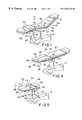
- FIG. 1is a perspective view of a first embodiment of a surgical table apparatus of the present invention including a one-piece, two section leg support;
- FIG. 2is a side elevational view of the surgical table apparatus of FIG. 1 illustrating pivotal movement of an upper support frame relative to a pedestal supported on a base about an axis transverse to a longitudinal axis of the upper support frame so that the upper support frame can be moved between a Trendelenburg position and a reverse Trendelenburg position;
- FIG. 3is an end view of the surgical table apparatus of FIG. 1 illustrating lateral tilting movement of the upper frame section relative to the pedestal about a longitudinal axis of the upper support frame;
- FIG. 4is a perspective view of another embodiment of the present invention including a two-piece leg support split along a longitudinal axis of the upper frame section;
- FIG. 5is a perspective view similar to FIG. 4 illustrating movement of the first and second leg support sections relative to the remainder of the upper support frame;
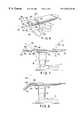
- FIG. 6is a perspective view of another embodiment of the present invention including a two-piece, two section leg support;
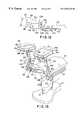
- FIG. 7is a side elevational view illustrating pivoting movement of the leg support sections of the surgical table apparatus about a first pivot axis and illustrating pivotal movement of a head frame section of the upper support frame;
- FIG. 8is a side elevational view similar to FIG. 7 illustrating pivotal movement of the leg support sections about a second pivot axis
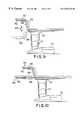
- FIG. 9illustrates further pivotal movement of the leg support sections relative to the remainder of the upper support frame
- FIG. 10illustrates independent pivotal movement of the two-piece leg support sections of the surgical table apparatus
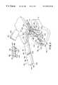
- FIG. 11is a perspective view illustrating further details of the leg support sections of the embodiment of FIG. 6;
- FIG. 12is a side elevational view illustrating additional details of a linkage for coupling the leg support sections of FIG. 11 to the upper support frame;
- FIG. 13illustrates the leg support sections of FIG. 11 pivoted upwardly into urology and OB/GYN leg support positions
- FIG. 14is a perspective view illustrating a one-piece head support of the present invention.
- FIG. 15is a perspective view similar to FIG. 14 illustrating movement of the head support to adjust the length of the head support;
- FIG. 16is a perspective view illustrating the head support pivoted upwardly to provide support for a side of a patient's head
- FIG. 17illustrates pivotal movement of the head support to provide a head support for a patient in a supine position or an airway access head support for a patient in a prone position;
- FIG. 18is a perspective view of a two-piece head support of the present invention.
- FIG. 19illustrates movement of the head support to extend the length of the head support and pivotable movement of an inner support section to provide airway access when the patient is in a prone position
- FIG. 20is a perspective view illustrating an inner support section in a downwardly pivoted position and an outer support section in an upwardly pivoted position to provide lateral support for the side of a patient's head;
- FIG. 21is a perspective view illustrating the outer support section in a downwardly pivoted position so that the inner support section supports the patient's neck while providing full head access to the patient.
- FIG. 1illustrates a first embodiment of a surgical table apparatus 10 in accordance with the present invention.
- the apparatus 10includes a base 12 and a pedestal 14 coupled to the base 12 .
- An upper support frame 16is coupled to the pedestal 14 .
- the upper support frame 16includes a head section 18 , a back section 20 , a seat section 22 , and a leg section 24 .
- the pedestal 14includes a hi/lo mechanism (not shown) for moving the telescoping pedestal 14 upwardly and downwardly in the direction of double-headed arrow 26 to raise and lower the upper support frame 16 relative to the ground.
- the upper support frame 16is coupled to a convex bearing surface 28 which is then coupled to a concave bearing surface 30 on the pedestal 14 .
- a driver(not shown) such as a cylinder, gear, or other mechanism is used to provide powered pivotable movement of the upper support frame 16 about transverse pivot axis 32 in both directions to move the upper support surface 16 between a Trendelenburg position a reverse Trendelenburg position as illustrated by the dotted line positions shown in FIG. 2 .
- Bearing portion 28also includes a concave bearing surface 34 extending along a longitudinal axis 36 of the upper support frame 16 as shown in FIG. 3 .
- Upper support frame 16is coupled to a convex bearing surface 38 configured to engage bearing surface 34 and permit rotation of the upper support frame 16 about axis 36 to provide lateral tilting of the upper support frame 16 to the dotted positions shown in FIG. 3 .
- Appropriate cylinders, gears, or other drive mechanismsare used to provide powered lateral rotational movement of the upper support frame 16 about axis 36 .
- the surgical table apparatus 10includes mattress sections 40 located on each of the upper frame sections 18 , 20 , 22 , and 24 to support a patient.
- Mattress sections 40can be any type of support surface including foam, air, gel, liquid, air fluidized or other support material.
- Back frame section 20is pivotably coupled to seat frame section 22 about transverse pivot axis 44 .
- Leg support 24includes a first frame section 46 pivotably coupled to seat section 22 about pivot axis 48 .
- a second leg frame section 50is pivotably coupled to section 46 about pivot axis 52 .
- Separate mattress portions 40are located above the first leg frame section 46 and the second leg frame section 50 .
- Accessory rails 54are mounted to various frame sections 20 , 22 , 46 , 50 of upper support frame 16 .
- Leg support 24is extendable relative to the seat section 22 by extendable arms located between the first frame section 46 and the seat frame section 22 or between the first and second frame sections 46 and 50 .
- leg support 24is removable from the seat section by the caregiver without the use of tools as discussed below.
- FIGS. 4 and 5illustrate another embodiment of a leg support 56 .
- the leg support 56is a two-piece support including separate leg support sections 58 and 60 which are split along the longitudinal axis 36 of the upper support frame 16 .
- Each of the first and second leg support sections 58 and 60include first frame member 62 pivotably coupled to seat frame section 22 about pivot axis 48 .
- Second leg frame sections 64are pivotably coupled to first frame sections 62 about pivot axis 52 .
- First and second leg sections 58 and 60are also pivotable outwardly about a first axis 66 and a second axis 68 , respectively, as illustrated by arrows 70 and 72 in FIG. 5 . Therefore, first and second leg support sections 58 and 60 can be pivoted outwardly relative to the remainder of upper support frame 16 as illustrated by the dotted line positions 58 and 60 in FIG. 5 .
- First and second leg support sections 58 and 60also include telescoping portions which slide into the seat frame section 22 and permit the first and second leg sections 60 to be moved in the direction of arrows 74 to lengthen the leg support section 56 .
- First and second leg support sections 58 and 60removable as discussed below.
- FIG. 6illustrates another embodiment of the present invention in which the surgical table apparatus 10 includes a two-piece, two section leg support 79 having first and second leg support sections 80 and 82 split along longitudinal axis 36 .
- Each of the first and second leg support sections 80 and 82includes a first frame section 38 pivotably coupled to the seat section about pivot axis 48 .
- a second frame section 90is pivotably coupled to first frame section 88 about pivot axis 52 .
- first and second leg support sections 80 and 82are pivotably coupled to seat section 22 about vertical pivot axes 90 and 92 , respectively, as discussed in detail below. Therefore, first and second leg support sections 80 and 82 can pivot outwardly in the direction of arrows 94 and 96 , respectively, similar to leg sections 58 and 60 shown in FIGS. 4 and 5.
- FIGS. 7-10Articulation of the leg supports 24 , 56 , and 79 of the present invention is illustrated in detail with reference to FIGS. 7-10.
- the FIG. 6 embodimentis used to illustrate pivotable movement of the leg supports 24 , 56 , and 79 .
- FIG. 7also illustrates upward pivotal movement of the head frame section 20 relative to the seat frame section 22 .
- Each of the leg supports 24 , 56 , and 79can pivot about the first transverse pivot axis 48 through range of motion of +/ ⁇ 90°. Illustrated movement of leg section 79 about pivot axis 48 is shown in FIG. 7 . Each of the leg supports 24 , 56 , and 79 can also pivot about the second transverse pivot axis 52 through a range of motion of +/ ⁇ 90° relative to the adjacent frame section. Illustrative movement of frame members 90 of foot section 79 relative to frame members 88 is shown in FIG. 8 When pivoted upwardly to the dotted line position of FIG. 8, frame member 90 may be used as a foot prop for the patient. It is understood that foot frame sections 50 and 64 of leg supports 24 and 56 , respectively, can also pivot in a manner similar to FIG. 8 about pivot axis 52 .
- FIG. 9illustrates another possible configuration for leg supports 24 , 56 , and 79 . Since the separate frame members 88 and 90 of leg support section 79 are independently pivotable, the leg section can assume numerous desired configurations depending on a particular surgical procedure.
- FIG. 10illustrates the first and second leg support sections 80 and 82 of leg support 79 in different configurations. The embodiments in FIGS. 4-6 can assume different orientations with each leg support section 58 , 60 or 80 , 90 since these leg support sections are independently adjustable.
- FIG. 9also illustrates that first and second leg support sections are extendable as illustrated by dimension 98 as discussed in detail below.
- first frame section 88is pivotably coupled to a clevis 100 about axis 48 .
- the clevis 100has spaced-apart side flanges 102 configured to receive an end of the frame section 88 for pivotably coupling the frame section 88 member to the clevis 100 .
- clevis 100further includes a mounting portion 104 having an aperture configured to receive a post 106 extending upwardly from coupler 108 . Latches 107 actuatable by a caregiver without the use of tools are provided to secure the coupler 108 to the clevis 100 . Therefore, leg support sections 80 , 82 are easily removable for replacement with other leg supports 24 or 56 or for better access to end 109 of seat section 22 for access to the patient.
- Coupler 108is pivotably coupled to the seat frame section 22 about pivot connection 112 .
- a cylinder 114is pivotably coupled to a flange 116 extending from seat frame section 22 by pivot connection 118 .
- a piston 120is pivotably coupled to coupler 108 by pivot connection 122 .
- Piston 120is movable from a retracted position shown in solid lines in FIG. 12 to an extended position. In the extended position, the piston moves the coupler 108 , the clevis 100 , and the leg frame section 88 upwardly to the dotted position shown in FIG. 12 to elevate the leg support section 82 relative to the seat support section 22 .
- the coupler 108is coupled to an arm member which is slidably received within an aperture of seat frame section 22 to permit the entire leg support section 82 to slide inwardly and outwardly relative to the seat support section 22 to lengthen the leg support section 82 .
- Frame member 88is pivotably coupled to frame member 90 by joint connection 124 .
- Joint connection 124is either articulated by a piston and cylinder arrangement similar to FIG. 12 or is manually operatable with a suitable joint 124 which is rigid enough to support the patient.
- All the joint connections of the present inventionmay be any suitable clutch assembly or latch mechanism.
- the latch mechanismsmay include separate mating portions including a plurality of teeth to permit the joint to be pivoted to a desired location and then held in that location by the joint.
- Frame member 90may also be mounted to a separate arm which is slidably received in frame member 88 to permit the length of leg support section 79 to be further adjusted as discussed below with reference to FIG. 13 .
- Frame section 90includes a curved portion 126 and a cylindrical end portion 128 .
- Cylindrical end portion 128includes a socket and slot 130 configured to receive a ball 132 therein.
- a post 134 coupled to ball 132 , post 134is also coupled to a connector 136 of foot support 86 . Therefore, foot support 86 is pivotably coupled to the cylindrical portion.
- a handle 138 coupled to cylindrical portion 128is configured to lock the ball 132 and post 134 in a desired orientation. The handle 138 is actuated either by movement toward frame section 90 or by rotational movement.
- the post 134is rotatable about a first axis 140 when in the position of FIG. 11 .
- the post 134can also be rotated toward a foot end of the table 10 to lie within slot 130 and then rotate about axis 142 .
- the foot support 86includes separate panels or portions 144 and 146 coupled together by a hinge or coupler 148 as illustrated in FIG. 11.
- a mattress portion 40is located above both panels 144 and 146 .
- Thigh panels 84are coupled to frame sections 88 by connectors 150 .
- Connector 150may be any suitable connector such as a latch, clamp, etc.
- the connector 150may also be a tab configured to enter the slot 151 formed between frame member 88 and accessory rail 54 .
- the thigh panels 84are removable so that the leg support sections 80 and 82 can be articulated upwardly as shown in FIG. 13 to urology and OB/GYN examination positions.
- the foot panels 86are manually adjustable into folded positions shown in dotted lines in FIG. 13 to form concave calf supports.
- FIG. 13also illustrates a separate arm 152 pivotably coupled to frame member 90 about axis 52 .
- the arm 152is slidably received within frame member 88 so that the arm 152 may be extended to adjust the length of the leg support sections as illustrated by dimension 154 .
- leg sections 80 and 82may be manually or automatically moved to desired positions.
- handle actuator 138is actuated to release the ball 132 and permit the ball 132 to be rotated within slot 130 so that the post 134 extends upwardly to provide the calf supports.
- the removable leg supports 24 , 56 and 79provide a flexible surgical table apparatus 10 which can be modified by a caregiver as desired quickly and easily without the use of separate tools.
- Leg supports 24 , 56 and 79are removable to expose the end 109 of seat section 20 to provide better access to the patient during certain medical procedures.
- the removable leg supports 24 , 56 and 79permit the leg supports 24 , 56 and 79 to be interchangeable on the of the surgical table apparatus 10 .
- the removable leg supports 24 , 56 and 79also permit attachment of special orthopaedic frames to the seat frame section 22 for orthopedic surgery.
- Each of the leg supports 24 , 56 and 79includes an arm and a support coupled to the arm.
- Each of the leg supports 24 , 56 and 79is also length adjustable relative to the seat frame section 22 . This permits flexibility of the caregiver in positioning the leg supports 24 , 56 and 79 at a desired location to align the patient in a desired position for a surgical procedure. Since the leg supports 24 , 56 , and 79 are all pivotable about two pivot axes 48 , 52 , the leg supports 24 , 56 , and 79 can be articulated to provide a knee shelf for the patient in a prone position without requiring separate components to be attached to the upper support frame 16 . In addition, a foot prop position and a knee gatch position are easily obtainable by the leg supports 24 , 56 , and 79 without separate attachments.
- FIGS. 14-17illustrate a one-piece head support 160 of the present invention.
- Head support 160includes a pair of spaced-apart arms 162 which are received within slots formed in head frame section 20 . Arms 162 are pivotably coupled to a second pair of arms 164 by joints 166 so that arms 162 and 164 can pivot about pivot axis 168 as shown by doubleheaded arrow 170 in FIG. 14.
- a bottom plate 172is pivotably coupled to arms 164 by joint connections 174 . Therefore, plate 172 can pivot relative to arms 164 about axis 176 as illustrated by doubleheaded arrow 178 in FIG. 14.
- a pad section 180is located over plate 172 .
- a U-shaped portion 182 of pad 180extends around an end edge 184 of plate 172 as best illustrated in FIGS. 16 and 17.
- the head support 160is movable to a plurality of different positions relative to the back frame section 20 to support the head and neck of a patient.
- a first positionis shown in FIG. 14 to provide head and neck support.
- Arms 162may be extended from the slots in head frame section 20 in the direction of arrow 186 in FIG. 14 to an extended position shown in FIG. 15 .
- Head support 160is also removable from head frame section 20 .
- Arms 164are also pivotable upwardly in the direction of arrow 188 in FIG. 16 to raise the pad 180 to a height above the level of mattress 40 on head frame section 20 .
- head support 160provides lateral support for a side of the patient's head when a patient is positioned on one side or another on the mattress 40 .
- Head support 160is also pivotable to the position shown in FIG. 17 to provide support for the patient's head only.
- the patient's headcan rest on the U-shaped portion of the pad in either a supine position or a prone position as shown in FIG. 17 .
- an opening 190is provided between the arms 164 and the plate 172 for airway access. Tubes or hoses 192 can be routed through the opening 190 to the patient 194 .
- the joint connections 166 and 174include suitable clutch assemblies which have, for instance, Belleville washers or other mechanisms to hold the arms 162 and 164 and plate 172 at desired relative positions. It is understood that other types of locking mechanisms or latches may be used. In addition, movement of the arms 162 and 164 and plate 172 may be controlled by suitable automatic controls, such as by cylinder and piston arrangements if desired.
- FIGS. 18-21disclose a two-piece head support 200 of the present invention.
- Head support 200includes an inner support section 202 and an outer U-shaped support section 204 .
- Inner support section 202includes an inner support plate 206 , and outer support section 204 on an outer support plate 208 .
- Head support 200includes a pair of spaced apart arms 210 which are received within slots formed in head frame section 20 .
- a pair of posts 212are rotatably coupled to arms 210 by joints 214 .
- Plate 206is coupled to posts 212 . Therefore, inner support section 202 is pivotably coupled to arms 210 by joints 214 about pivot axis 216 .
- Arms 218are pivotably coupled to the arms 210 by joints 214 , independently of posts 212 .
- arms 218can independently rotate about pivot axis 216 separately from inner support section 202 .
- Plate 208 of outer support section 204is pivotably coupled to arms 218 by joints 220 . Therefore, plate 208 can rotate about axis 222 relative to arms 218 .
- two-piece head support 200can be positioned as shown in FIG. 18 to provide both head and neck support for the patient.
- the entire head support 200is movable outwardly in the direction of arrow 224 by moving the arms 210 to the extended position shown in FIG. 19 .
- Head support 200is also removable from upper support frame 20 .
- Inner support section 202is pivotable downwardly in the direction of arrow 226 in FIG. 19 to provide an opening 228 for airway access when a patient is in a prone position on the mattress 40 .
- the patient's foreheadis supported by the outer support section 204 in the prone position.
- the inner support section 202is pivoted downwardly out of the way as shown in FIG. 20 .
- the second arms 218 and plate 208are pivoted so that the outer support section 204 is elevated relative to the mattress portion 40 on head frame section 20 . This provides lateral support for a side of a patient's head when the patient is located on one side or another on mattress 40 .
- plate 208 and arms 218are pivotable to the position shown in FIG. 21 .
- inner support section 202provides support for a patient's neck while providing fill head access to the patient during a procedure.
- the joint connections 214 and 220include suitable clutch assemblies which have, for instance, Belleville washers or other mechanisms to hold the position of arms 214 and 220 , posts 212 and plate 208 at desired relative positions. It is understood that other types of locking mechanisms or latches may be used. In addition, movement of the arms 210 and 218 , rods 212 and plate 208 may be controlled by suitable automatic controls, such as by cylinder and piston arrangements.
- FIGS. 15-21illustrate a pair of arms 162 , 164 , 210 , and 218 , it is understood that single arms may be used to support the head supports 160 , 200 .
- the arm coupled to the plates 172 and 208may be a single piece curved yoke attached to opposite sides of the plate, if desired.
Landscapes
- Health & Medical Sciences (AREA)
- Engineering & Computer Science (AREA)
- Biomedical Technology (AREA)
- Life Sciences & Earth Sciences (AREA)
- Animal Behavior & Ethology (AREA)
- General Health & Medical Sciences (AREA)
- Public Health (AREA)
- Veterinary Medicine (AREA)
- Gynecology & Obstetrics (AREA)
- Accommodation For Nursing Or Treatment Tables (AREA)
Abstract
Description
Claims (52)
Priority Applications (5)
| Application Number | Priority Date | Filing Date | Title |
|---|---|---|---|
| US09/187,990US6202230B1 (en) | 1997-11-07 | 1998-11-06 | Surgical table apparatus |
| US09/734,487US6276012B2 (en) | 1997-11-07 | 2000-12-11 | Surgical table apparatus |
| US09/934,226US6446287B2 (en) | 1997-11-07 | 2001-08-21 | Surgical table apparatus |
| US10/056,552US6754923B2 (en) | 1997-11-07 | 2002-01-25 | Leg section support for a surgical table |
| US10/056,959US6739006B2 (en) | 1997-11-07 | 2002-01-25 | Head section support for a surgical table apparatus |
Applications Claiming Priority (3)
| Application Number | Priority Date | Filing Date | Title |
|---|---|---|---|
| US6470997P | 1997-11-07 | 1997-11-07 | |
| US8367398P | 1998-04-30 | 1998-04-30 | |
| US09/187,990US6202230B1 (en) | 1997-11-07 | 1998-11-06 | Surgical table apparatus |
Related Child Applications (2)
| Application Number | Title | Priority Date | Filing Date |
|---|---|---|---|
| US09/734,487DivisionUS6276012B2 (en) | 1997-11-07 | 2000-12-11 | Surgical table apparatus |
| US09734487Division | 2001-12-11 |
Publications (1)
| Publication Number | Publication Date |
|---|---|
| US6202230B1true US6202230B1 (en) | 2001-03-20 |
Family
ID=26744812
Family Applications (3)
| Application Number | Title | Priority Date | Filing Date |
|---|---|---|---|
| US09/187,990Expired - LifetimeUS6202230B1 (en) | 1997-11-07 | 1998-11-06 | Surgical table apparatus |
| US09/734,487Expired - Fee RelatedUS6276012B2 (en) | 1997-11-07 | 2000-12-11 | Surgical table apparatus |
| US09/934,226Expired - Fee RelatedUS6446287B2 (en) | 1997-11-07 | 2001-08-21 | Surgical table apparatus |
Family Applications After (2)
| Application Number | Title | Priority Date | Filing Date |
|---|---|---|---|
| US09/734,487Expired - Fee RelatedUS6276012B2 (en) | 1997-11-07 | 2000-12-11 | Surgical table apparatus |
| US09/934,226Expired - Fee RelatedUS6446287B2 (en) | 1997-11-07 | 2001-08-21 | Surgical table apparatus |
Country Status (8)
| Country | Link |
|---|---|
| US (3) | US6202230B1 (en) |
| EP (2) | EP1525870A2 (en) |
| JP (1) | JP2001522649A (en) |
| AT (1) | ATE292450T1 (en) |
| AU (1) | AU1385399A (en) |
| CA (1) | CA2308032C (en) |
| DE (1) | DE69829689T2 (en) |
| WO (1) | WO1999023991A1 (en) |
Cited By (80)
| Publication number | Priority date | Publication date | Assignee | Title |
|---|---|---|---|---|
| US6398409B1 (en)* | 1999-03-16 | 2002-06-04 | Hill-Rom Services, Inc. | Patient support with digital X-ray cassette |
| US6446287B2 (en)* | 1997-11-07 | 2002-09-10 | Hill-Rom Services, Inc. | Surgical table apparatus |
| US6550084B2 (en) | 2001-06-19 | 2003-04-22 | The Brewer Company, Llc | Medical examination table step |
| US6568008B2 (en) | 2001-06-19 | 2003-05-27 | The Brewer Company, Llc | Medical examination table with two-way drawers and articulating backrest |
| US6615429B2 (en) | 1999-07-30 | 2003-09-09 | Hill-Rom Services, Inc. | Apparatus for positioning a patient-support deck |
| US6634043B2 (en)* | 1998-03-19 | 2003-10-21 | Orthopedic Systems, Inc. | Medical table having controlled movement and method of use |
| US6654974B2 (en) | 2000-06-02 | 2003-12-02 | Hill-Rom Services, Inc. | Foot support for a patient support |
| US6739006B2 (en) | 1997-11-07 | 2004-05-25 | Hill-Rom Services, Inc. | Head section support for a surgical table apparatus |
| US6754923B2 (en) | 1997-11-07 | 2004-06-29 | Hill-Rom Services, Inc. | Leg section support for a surgical table |
| US20040133979A1 (en)* | 2003-01-13 | 2004-07-15 | Newkirk David C. | Orthopedic table apparatus |
| US20040171974A1 (en)* | 2002-12-16 | 2004-09-02 | Cert Health Sciences, Llc | Method and apparatus for therapeutic treatment of back pain |
| US20040172758A1 (en)* | 2003-03-04 | 2004-09-09 | Shaji Alakkat | Method and apparatus for tilting in a patient positioning system |
| USD496462S1 (en) | 2003-09-29 | 2004-09-21 | The Brewer Company, Llc | Medical examination table |
| US20040205895A1 (en)* | 1999-10-12 | 2004-10-21 | Takano Co., Ltd. | Support structure for supporting a portion of a body |
| US20040226094A1 (en)* | 1998-08-07 | 2004-11-18 | Heimbrock Richard H. | OB/GYN stretcher |
| US20050067875A1 (en)* | 2003-09-29 | 2005-03-31 | The Brewer Company, Llc | Headrest linkage |
| US20050066861A1 (en)* | 2003-09-29 | 2005-03-31 | The Brewer Company, Llc | Lifting column for a medical examination table |
| US20050069377A1 (en)* | 2003-09-29 | 2005-03-31 | The Brewer Company, Llc | Stirrup support indexer for a medical examination table |
| US20050102755A1 (en)* | 2003-09-29 | 2005-05-19 | The Brewer Company, Llc | Leg rest and kneeler assembly for a medical examination table |
| US20050114996A1 (en)* | 2002-11-26 | 2005-06-02 | Baskar Somasundaram | Multiconfiguration braking system |
| USD507905S1 (en) | 2003-09-29 | 2005-08-02 | The Brewer Company, Llc | Lifting column |
| US20060042011A1 (en)* | 2002-11-19 | 2006-03-02 | Maquet Gmbh & Co. Kg | Leg support arrangement for operating tables |
| US7010369B2 (en) | 1997-11-07 | 2006-03-07 | Hill-Rom Services, Inc. | Medical equipment controller |
| US20060054395A1 (en)* | 2004-08-17 | 2006-03-16 | Horizon Veterinary Services, Inc. | Telescoping motorized lift platform |
| US20060070182A1 (en)* | 2004-09-22 | 2006-04-06 | Heimbrock Richard H | Storable foot section for a bed |
| US7024711B1 (en)* | 2000-08-31 | 2006-04-11 | Stasney T Glen | Sonography bed having patient support and sonographer access provisions |
| FR2878152A1 (en)* | 2004-11-22 | 2006-05-26 | Promotal Sa | Limb e.g. heel, resting device for e.g. gynecological examination, has limb support unit movable relative to connection arm, and locking/unlocking unit cooperating with axis between support unit`s maximal and null inclination positions |
| US20060123546A1 (en)* | 2004-12-10 | 2006-06-15 | Horton William C | Dynamic surgical table system |
| US20060253985A1 (en)* | 2004-11-10 | 2006-11-16 | Skripps Thomas K | Head support apparatus for spinal surgery |
| USD535544S1 (en) | 2005-07-28 | 2007-01-23 | The Brewer Company, Llc | Grab bar |
| US20070056102A1 (en)* | 2005-09-14 | 2007-03-15 | Midmark Corporation | Medical examination table with pullout step |
| US20070061971A1 (en)* | 2005-07-28 | 2007-03-22 | The Brewer Company, Llc | Medical examination table |
| US20070113345A1 (en)* | 2005-11-17 | 2007-05-24 | Hill-Rom Services, Inc. | Birthing bed foot support release handle |
| USD569520S1 (en) | 2005-07-28 | 2008-05-20 | Debraal Jack A | Medical examination table cabinet |
| US20080177211A1 (en)* | 2007-01-12 | 2008-07-24 | Boren John P | Machine and Method for Vertical Human Stretching |
| US20080176714A1 (en)* | 2007-01-12 | 2008-07-24 | Boren John P | Machine and Method for Head, Neck and, Shoulder Stretching |
| USD574959S1 (en) | 2005-07-28 | 2008-08-12 | Debraal Jack A | Medical examination table |
| USD574960S1 (en) | 2005-07-28 | 2008-08-12 | Parrish Vanessa B | Medical examination table top |
| US7536734B2 (en) | 2005-01-31 | 2009-05-26 | Hill-Rom Services, Inc. | Birthing support apparatus |
| US20100050343A1 (en)* | 2008-08-29 | 2010-03-04 | Hornbach David W | Patient-support apparatus with movable top |
| US20100064439A1 (en)* | 2008-09-12 | 2010-03-18 | Sohrab Soltani | Hospital chair beds with articulating foot sections |
| US20100187890A1 (en)* | 2009-01-27 | 2010-07-29 | Piretti Alessandro | Chair convertible into a chaise-longue |
| US20100192300A1 (en)* | 2008-10-28 | 2010-08-05 | Tannoury Tony Y | Prone and laterally angled surgical device and method |
| US20100223727A1 (en)* | 2009-03-03 | 2010-09-09 | Hill-Rom, Services, Inc. | Person-support apparatus with movable portions |
| US20110218086A1 (en)* | 2010-03-05 | 2011-09-08 | Boren John P | Apparatus and method of gravity-assisted spinal stretching |
| US20120117732A1 (en)* | 2010-11-16 | 2012-05-17 | O'keefe Christopher R | Fold down footboard |
| USD665912S1 (en) | 2006-04-11 | 2012-08-21 | Allen Medical Systems, Inc. | Head support pad for surgery |
| US8353071B2 (en) | 2010-12-01 | 2013-01-15 | Hill-Rom Services, Inc. | Removable integrated board and partial foot section |
| GB2498562A (en)* | 2012-01-20 | 2013-07-24 | Eschmann Holdings Ltd | Leg support for a surgical table |
| US8555439B2 (en) | 2010-11-18 | 2013-10-15 | Allen Medical Systems, Inc. | Padded head support |
| US8806679B2 (en) | 2010-11-18 | 2014-08-19 | Allen Medical Systems, Inc. | Operating room table adapter |
| US8844075B2 (en) | 2010-10-22 | 2014-09-30 | Hill-Rom Services, Inc. | Footboard with partial mattress integration |
| US8893333B2 (en) | 2010-11-18 | 2014-11-25 | Allen Medical Systems, Inc. | Surgical head support apparatus |
| US20150065862A1 (en)* | 2012-11-23 | 2015-03-05 | Hubert Noras | Device for the, in particular, transperineal examination of patients |
| US20150135441A1 (en)* | 2013-11-18 | 2015-05-21 | Schaerer Medical Management Ag | Modular Operating Table |
| US9038216B2 (en) | 2005-07-28 | 2015-05-26 | The Brewer Company, Llc | Medical examination table |
| US20150245970A1 (en)* | 2012-01-10 | 2015-09-03 | Alessio Pigazzi | Method of Securing a Patient onto an Operating Table when the Patient is in the Trendelenburg Position and Apparatus Therefor Including a Kit |
| US20160074264A1 (en)* | 2014-09-17 | 2016-03-17 | Kevin R. Davis | Pulmonary prone bed |
| US20160089287A1 (en)* | 2013-05-03 | 2016-03-31 | MAQUET GmbH | Operating table and method for controlling an operating table |
| US9622827B2 (en) | 2015-05-15 | 2017-04-18 | Auris Surgical Robotics, Inc. | Surgical robotics system |
| US20170151115A1 (en)* | 2005-02-22 | 2017-06-01 | Roger P. Jackson | Modular multi-articulated patient support system |
| US20170216122A1 (en)* | 2016-02-03 | 2017-08-03 | White Surgical Incorporated | Modular patient positioning system |
| US10159533B2 (en) | 2014-07-01 | 2018-12-25 | Auris Health, Inc. | Surgical system with configurable rail-mounted mechanical arms |
| US10188567B2 (en) | 2014-10-30 | 2019-01-29 | Byron Wade Wurdeman | Hospital chair beds with extendable/retractable foot sections |
| US10188573B2 (en) | 2014-11-05 | 2019-01-29 | Allen Medical Systems, Inc. | Boot stirrup |
| US20190083183A1 (en)* | 2015-04-09 | 2019-03-21 | Auris Health, Inc. | Surgical system with configurable rail-mounted mechanical arms |
| US10285890B1 (en) | 2012-01-10 | 2019-05-14 | Alessio Pigazzi | Method of securing a patient onto an operating table when the patient is in a position such as the Trendelenburg position and apparatus therefor including a kit |
| US10517692B2 (en) | 2018-01-17 | 2019-12-31 | Auris Health, Inc. | Surgical platform with adjustable arm supports |
| US10760606B2 (en)* | 2015-07-24 | 2020-09-01 | MAQUET GmbH | Adjusting device for positioning support surface segments of an operating table |
| US10799412B1 (en)* | 2019-12-31 | 2020-10-13 | Zafer Termanini | Surgical table for direct anterior surgical approach of the hip |
| US10835431B2 (en)* | 2013-06-06 | 2020-11-17 | MAQUET GmbH | Apparatus and method for controlling an operating table |
| US10857052B1 (en)* | 2016-08-31 | 2020-12-08 | Pivotal Health Solutions, Inc. | Treatment table for therapeutic treatment, physical rehabilitation and training and method of use |
| US10869801B1 (en)* | 2017-12-14 | 2020-12-22 | Kyra Medical, Inc | Limb holder apparatus and related methods |
| US10912699B2 (en) | 2012-01-10 | 2021-02-09 | Alessio Pigazzi | Method of securing a patient onto an operating table when the patient is in a position such as the trendelenburg position and apparatus therefor including a kit |
| US10945904B2 (en) | 2019-03-08 | 2021-03-16 | Auris Health, Inc. | Tilt mechanisms for medical systems and applications |
| US11202683B2 (en) | 2019-02-22 | 2021-12-21 | Auris Health, Inc. | Surgical platform with motorized arms for adjustable arm supports |
| US11266525B2 (en) | 2016-01-21 | 2022-03-08 | Xodus Medical, Inc. | Patient warming device for surgical procedures |
| USD953770S1 (en)* | 2020-06-23 | 2022-06-07 | Importla, Llc | Adjustable bed |
| US20230095554A1 (en)* | 2021-09-29 | 2023-03-30 | Stryker Corporation | Patient Transport Apparatus Having An Extender for a Head Deck Section |
| NL2038091B1 (en)* | 2024-06-28 | 2025-03-06 | The Second Affiliated Hospital And Yuying Childrens Hospital Of Wenzhou Medical Univ | Delivery auxiliary device for obstetrics and gynecology |
Families Citing this family (106)
| Publication number | Priority date | Publication date | Assignee | Title |
|---|---|---|---|---|
| US6397414B1 (en)* | 2000-06-21 | 2002-06-04 | John T. Lloyd | Adjustable face rest |
| JP2002253625A (en)* | 2001-03-06 | 2002-09-10 | Tabuchi Kazuhisa | Sitting delivery bed |
| NL1020201C1 (en)* | 2002-03-19 | 2003-09-23 | Paul Arthur Engels | Adjustable chair for medical and paramedical diagnosis and treatment. |
| AU2003285047B2 (en)* | 2002-10-29 | 2008-06-05 | Djo, Llc | Therapeutic exercise device |
| DE20217825U1 (en) | 2002-11-18 | 2003-01-16 | MAQUET GmbH & Co. KG, 76437 Rastatt | Headrest for patient storage area |
| US6826794B2 (en) | 2003-01-14 | 2004-12-07 | Surgical Devices, Inc. | Apparatus and method for positioning a patient during surgery |
| JP4231363B2 (en)* | 2003-07-15 | 2009-02-25 | フランスベッド株式会社 | Back-up bed equipment |
| US6926366B2 (en)* | 2003-10-15 | 2005-08-09 | Midmark Corporation | Universal power table |
| RU2277404C2 (en)* | 2004-03-23 | 2006-06-10 | Евгений Эвальевич Блюм | Method and device for assisting at childbirth |
| US7341565B2 (en)* | 2004-04-02 | 2008-03-11 | Suncepts, Inc. | Passive motion machine providing controlled body motions for exercise and therapeutic purposes |
| US20050235424A1 (en)* | 2004-04-26 | 2005-10-27 | Ruel Waite | Easy change baby station |
| US8112942B2 (en)* | 2004-05-13 | 2012-02-14 | Nbbj Design Llp | Operating room/intervention room |
| US8905585B2 (en)* | 2004-05-13 | 2014-12-09 | Or21, Llc | Operating room/intervention room |
| US7036168B1 (en) | 2004-05-24 | 2006-05-02 | Kristin Knickerbocker | Portable headrest |
| WO2006013185A1 (en)* | 2004-07-30 | 2006-02-09 | Siemens Aktiengesellschaft | Restraining device for the head of a patient |
| USD536096S1 (en)* | 2004-09-22 | 2007-01-30 | Joimax Gmbh | Operation table |
| USD509079S1 (en)* | 2004-10-29 | 2005-09-06 | Natuzzi S.P.A. | Chair |
| US7654974B2 (en)* | 2005-04-01 | 2010-02-02 | David B. Bass | Recliner spinal traction device |
| JP5186369B2 (en)* | 2005-08-10 | 2013-04-17 | ミズホ・オーソペディック・システムズ・インク | Treatment table with controlled operation and method of using the same |
| FR2909549A1 (en)* | 2006-12-12 | 2008-06-13 | Pascal Charles Antoine Poyet | Hospital bed for e.g. patient with reduced mobility, has head section moved away laterally from head section to release head separation edge in opening position for permitting patient to lift bed by passing through head separation edge |
| FR2909550B1 (en)* | 2006-12-12 | 2009-03-06 | Pascal Charles Antoine Poyet | MEDICALIZED BED WITH LATERAL TRANSLATION |
| FR2909547A1 (en)* | 2006-12-12 | 2008-06-13 | Pascal Charles Antoine Poyet | Medicalized bed for e.g. retirement home, has lateral releasing unit for laterally moving seat relative to legrest of bedding plane or vice-versa when junction unit is in dissociation configuration, for releasing frontal access to seat |
| US7611207B2 (en) | 2007-06-01 | 2009-11-03 | Linda Barfuss | Salon chair having movable foot rest |
| US7496979B2 (en)* | 2007-06-27 | 2009-03-03 | Midmark Corporation | Patient table with footrest extension |
| US8641147B2 (en)* | 2007-06-29 | 2014-02-04 | Midmark Corporation | Procedure chair with interchangeable headrests |
| FR2919479A1 (en)* | 2007-08-03 | 2009-02-06 | Pascal Charles Antoine Poyet | Medicalized furniture e.g. medicalized bed, for e.g. intensive care, has barrier configuration unit comprising hinge adjustment unit for modifying spatial configuration of hinge with respect to base |
| CN101795601A (en)* | 2007-08-30 | 2010-08-04 | 加勒特·W·布朗 | Articulated human arm support |
| US7770977B2 (en)* | 2007-09-20 | 2010-08-10 | Midmark Corporation | Floating bearing and clamp system for patient procedures chair mounting and positioning posts |
| CN201119969Y (en)* | 2007-10-31 | 2008-09-24 | La国际集团有限公司 | Tattoo chair |
| US8819879B1 (en)* | 2007-11-13 | 2014-09-02 | Encore Medical Asset Corporation | Therapeutic treatment table |
| DE102008053566A1 (en)* | 2007-11-27 | 2009-06-04 | Bernhard Hildebrandt | System of endoprostheses and devices for the minimally invasive and cementless implantation of endoprostheses of the shoulder and the hip and the offset improvement of the femoral neck |
| USD603967S1 (en)* | 2007-12-21 | 2009-11-10 | Wake Forest University Health Sciences | Surgical head support adapter |
| JP5368012B2 (en)* | 2008-06-19 | 2013-12-18 | アトムメディカル株式会社 | Delivery table |
| USD636493S1 (en)* | 2008-11-12 | 2011-04-19 | Encore Medical Asset Corporation | Therapy table |
| US10231891B2 (en)* | 2009-03-13 | 2019-03-19 | Hill-Rom Services, Inc. | Modular fluidizable occupant support and compact fluidizable modules |
| US8209802B2 (en)* | 2009-04-08 | 2012-07-03 | Linares Medical Devices, Llc | Combination medical support table and portable convertible stretcher unit |
| JP6014952B2 (en)* | 2009-09-03 | 2016-10-26 | 株式会社吉田製作所 | Head-back tilt mechanism of the medical chair |
| WO2011081774A2 (en) | 2009-12-14 | 2011-07-07 | Hill-Rom Services, Inc. | Patient support apparatuses with exercise functionalities |
| CN201603304U (en)* | 2010-02-09 | 2010-10-13 | 四川瑞迪医疗科技有限公司 | Lithotomy position after-loading carbon fiber treatment bed used for image guidance |
| US20110277399A1 (en)* | 2010-05-13 | 2011-11-17 | Boekeloo Stuart W | Multi-Function Medical Room System |
| ES2380258B1 (en)* | 2010-06-01 | 2013-03-15 | Photon Mundial, S.L. | MULTIPOSITIONAL ANATOMICAL RELAXATION AND STRETCHING STRETCH |
| US8713727B2 (en) | 2010-07-30 | 2014-05-06 | Hill-Rom Services, Inc. | Siderail assembly for patient support apparatus |
| US8651569B2 (en) | 2010-09-07 | 2014-02-18 | InkBed, Inc. | Apparatus for support during tattooing |
| CN101966115B (en)* | 2010-09-27 | 2012-06-13 | 江苏苏云医疗器材有限公司 | Treatment table |
| US8732876B2 (en)* | 2010-09-29 | 2014-05-27 | Hill-Rom Services, Inc. | Upper body support mechanism |
| US8677535B2 (en)* | 2010-10-08 | 2014-03-25 | Hill-Rom Services, Inc. | Patient support apparatus with storable egress handles |
| US8745786B2 (en) | 2010-11-10 | 2014-06-10 | Hill-Rom Services, Inc. | Siderail assembly for patient support apparatus |
| US8621688B2 (en) | 2010-12-13 | 2014-01-07 | Hill-Rom Services, Inc. | Siderail assembly for patient support apparatus |
| EP2566294A1 (en) | 2011-08-31 | 2013-03-06 | Koninklijke Philips Electronics N.V. | Appliance control device |
| DE102011115097A1 (en)* | 2011-10-07 | 2013-04-11 | Gharieni Gmbh | treatment table |
| US9233043B2 (en) | 2012-01-26 | 2016-01-12 | American Sterilizer Company | Femur support for a medical table |
| AU2013214928B2 (en) | 2012-02-03 | 2018-06-28 | Amenity Health, Inc. | Therapeutic cushion systems and methods |
| WO2013158580A2 (en)* | 2012-04-17 | 2013-10-24 | Ferno-Washington, Inc. | Adjustable head rest assemblies for patient positioning and patient support apparatus including adjustable head rest assemblies |
| US20130281264A1 (en)* | 2012-04-19 | 2013-10-24 | Her-Fa Chen | Swimming exercise device |
| US9603765B2 (en)* | 2012-09-13 | 2017-03-28 | Innovative Orthopedic Technologies, Llc | Telescoping and elevating femoral support |
| ITMI20121546A1 (en)* | 2012-09-18 | 2014-03-19 | Medacta Int Sa | ADAPTER FLOOR FOR SURGICAL TABLE, IN PARTICULAR FOR REPLACEMENT OPERATIONS OF THE HOOK WITH FRONT APPROACH |
| US8640286B1 (en)* | 2012-12-20 | 2014-02-04 | Leon Hochman | Medical bed |
| GB2520046B (en)* | 2013-11-07 | 2016-01-13 | Univ Cape Town | Anatomical support facilitating medical imaging of the hip, leg and knee |
| US10524573B2 (en) | 2014-01-09 | 2020-01-07 | InkBed, Inc. | Stools, chairs, and methods using the same |
| CN112932124A (en) | 2014-01-09 | 2021-06-11 | 墨床有限公司 | Stool, chair and method of using stool, chair |
| US9084486B1 (en) | 2014-01-09 | 2015-07-21 | InkBed, Inc. | Tattoo stools and chairs and methods using the same |
| US9038218B1 (en) | 2014-01-15 | 2015-05-26 | Hill-Rom Services, Inc. | Person support apparatuses with selectively coupled foot sections |
| US9132051B2 (en) | 2014-01-15 | 2015-09-15 | Hill-Rom Services, Inc. | Person support apparatuses with exercise functionalities |
| US9463126B2 (en) | 2014-03-11 | 2016-10-11 | Hill-Rom Services, Inc. | Caregiver universal remote cart for patient bed control |
| WO2015170257A1 (en)* | 2014-05-05 | 2015-11-12 | Gymnauniphy | Treatment couch with face pillow part in elastic foam |
| BE1021344B1 (en)* | 2014-05-05 | 2015-11-05 | Gymnauniphy | TREATMENT BENCH WITH FACIAL PILLOW SECTION IN ELASTIC FOAM |
| BE1021308B1 (en)* | 2014-05-05 | 2015-10-27 | Gymnauniphy | TREATMENT BENCH WITH REMOVABLE FACE PILLOW PART |
| KR101570611B1 (en) | 2014-07-07 | 2015-11-19 | 한국생산기술연구원 | Diagnosis and Oparation Assisting Apparatus having Ball-Socket Joint and Hinge Joint |
| US10349752B2 (en) | 2014-08-08 | 2019-07-16 | Amenity Health, Inc. | Therapeutic cushion systems and methods |
| US11234533B2 (en) | 2014-08-08 | 2022-02-01 | Amenity Health, Inc. | Therapeutic cushion systems and methods |
| US9427366B2 (en)* | 2014-08-08 | 2016-08-30 | Amenity Health, Inc. | Therapeutic cushion systems and methods |
| WO2016049696A1 (en)* | 2014-09-30 | 2016-04-07 | Abraham, Cynthia | Bed and bed insert with postural support |
| CN104622660A (en)* | 2015-01-21 | 2015-05-20 | 付积杰 | Operating table used in orthopedic department |
| CN104771285B (en)* | 2015-03-20 | 2017-03-01 | 张家亮 | Electric up-down surgery table |
| US20180177657A1 (en)* | 2015-06-03 | 2018-06-28 | Korea Institute Of Oriental Medicine | Integrated bed for oriental medicine therapy |
| US9498398B1 (en)* | 2015-07-22 | 2016-11-22 | Eb-Invent Gmbh | Massage chair and table |
| CN105055105B (en)* | 2015-08-21 | 2017-03-01 | 江苏科凌医疗器械有限公司 | A kind of operation table |
| CN106137655A (en)* | 2016-08-10 | 2016-11-23 | 巴豪斯医疗器械(苏州)有限公司 | A kind of operation table |
| CZ307343B6 (en) | 2016-09-20 | 2018-06-20 | BORCAD Medical a.s. | A medical device |
| US10881567B2 (en) | 2016-10-28 | 2021-01-05 | Stryker Corporation | Patient support apparatus |
| US10744053B2 (en) | 2016-12-07 | 2020-08-18 | Stryker Corporation | Haptic systems and methods for a user interface of a patient support apparatus |
| USD841819S1 (en) | 2017-05-30 | 2019-02-26 | Amenity Health, Inc. | Therapeutic cushion |
| CN107184356A (en)* | 2017-06-26 | 2017-09-22 | 新生医疗美容有限公司 | A kind of intelligent hair transplant controllable operation table |
| CN107361980A (en)* | 2017-08-09 | 2017-11-21 | 郑敏 | A kind of gynemetrics is clinical to use pre-natal diagnosis check device |
| DE102017127177A1 (en)* | 2017-11-17 | 2019-05-23 | MAQUET GmbH | One-handed adjustable head plate for an operating table |
| US10632037B2 (en) | 2018-02-01 | 2020-04-28 | Medical Technology Industries, Inc. | Programmable examination and procedure tables and chairs |
| US10973332B2 (en) | 2018-02-13 | 2021-04-13 | InkBed, Inc. | Chairs with adjustable back supports |
| WO2019161124A1 (en) | 2018-02-14 | 2019-08-22 | InkBed, Inc. | Stools and chairs with translatable armrests |
| WO2019183293A1 (en) | 2018-03-22 | 2019-09-26 | Johnson David A | Adaptive ergonomic positioning device |
| CN108784954A (en)* | 2018-05-31 | 2018-11-13 | 潘真清 | A kind of wheelchair |
| CN108743077B (en)* | 2018-06-29 | 2020-03-31 | 青岛市中心医院 | A temperature-adjustable patient wheelchair for post-operative patient rehabilitation |
| USD954964S1 (en)* | 2018-07-27 | 2022-06-14 | United Metal Fabricators, Inc. | Medical examination table |
| CN111228050A (en)* | 2018-09-30 | 2020-06-05 | 日照轩宜信息科技有限公司 | Chair for administration and rescue of unconscious old people |
| CN109316306A (en)* | 2018-10-20 | 2019-02-12 | 隋艳芬 | A kind of multi-functional bed for obstetrical department |
| TWI672133B (en)* | 2018-11-29 | 2019-09-21 | 上銀科技股份有限公司 | Clamping mechanism |
| CN111281725B (en)* | 2018-12-07 | 2021-10-08 | 上银科技股份有限公司 | Clamping mechanism |
| JP7170317B2 (en)* | 2019-01-17 | 2022-11-14 | 株式会社東機貿 | Tabletop and detachable operating table |
| AU2020276338B2 (en)* | 2019-05-10 | 2025-02-27 | QOL Holdings Pty Ltd | Foot positioning assembly |
| CN111329708A (en)* | 2020-03-13 | 2020-06-26 | 孙冰 | Auxiliary instrument for anorectal examination |
| US11963918B2 (en) | 2020-04-20 | 2024-04-23 | Hill-Rom Services, Inc. | Patient bed having active motion exercise |
| US11529276B2 (en) | 2020-10-23 | 2022-12-20 | Hill-Rom Services, Inc. | Proning frame for a patient bed |
| US12414887B2 (en)* | 2020-10-23 | 2025-09-16 | Hill-Rom Services, Inc. | Proning frame for a patient bed |
| CN113274052A (en)* | 2021-05-10 | 2021-08-20 | 深圳市东恒尚科信息技术有限公司 | Artificial intelligence medical diagnosis system |
| KR102725272B1 (en)* | 2022-02-24 | 2024-11-01 | 주식회사 헬스메이커 | Exercise assistance apparatus |
| KR102809600B1 (en)* | 2022-12-23 | 2025-05-21 | 동국대학교 산학협력단 | Headrest for surgery |
| WO2025030063A1 (en)* | 2023-08-01 | 2025-02-06 | InkBed, Inc. | Portable and modular tattoo support apparatus |
Citations (59)
| Publication number | Priority date | Publication date | Assignee | Title |
|---|---|---|---|---|
| US12944A (en) | 1855-05-29 | Istvalib-bedstead | ||
| US238799A (en)* | 1881-03-15 | Invalid-bed | ||
| US1437568A (en) | 1922-01-14 | 1922-12-05 | George C Taplin | Operating table |
| US1626091A (en) | 1924-02-07 | 1927-04-26 | Jesse W Macklin | Osteopathic operating table |
| US1775547A (en)* | 1922-04-17 | 1930-09-09 | Simmons Co | Hospital bedstead |
| US2042399A (en) | 1934-06-12 | 1936-05-26 | Edward D Holme Jr | Combined chair and table |
| US2258782A (en) | 1939-12-19 | 1941-10-14 | Rogers W Mckean | Physician's examining table |
| US2872259A (en)* | 1956-11-26 | 1959-02-03 | Allen & Hanburys Ltd | Operation tables having removably supported interchangeable head and leg extension sections |
| US2972505A (en) | 1959-09-16 | 1961-02-21 | Ritter Co Inc | Arm rest for surgical tables |
| US3041122A (en)* | 1960-09-26 | 1962-06-26 | Ritter Co Inc | Surgical table |
| US3041121A (en) | 1960-09-26 | 1962-06-26 | Ritter Co Inc | Surgical table |
| US3227440A (en) | 1962-03-09 | 1966-01-04 | Simmons Co | Operating table having a plurality of body supporting tops |
| US3281141A (en)* | 1963-01-15 | 1966-10-25 | American Sterilizer Co | Surgical table |
| GB1058787A (en) | 1964-05-15 | 1967-02-15 | American Sterilizer Co | Surgical table |
| DE1258021B (en) | 1962-07-11 | 1968-01-04 | Ritter Co Inc | Multi-part medical examination table with two-part leg plate |
| FR1518724A (en) | 1966-12-29 | 1968-03-29 | Alexandre Et Cie | Breaking control of elements of an operating table from the longitudinal sliding of the plate |
| US3411766A (en) | 1966-02-23 | 1968-11-19 | American Hospital Supply Corp | Operating table |
| US3754749A (en)* | 1971-06-25 | 1973-08-28 | Medical Eng Dev Co | Multi-articulated table |
| US3868103A (en) | 1973-04-24 | 1975-02-25 | Millet Roux & Cie Ltee | Surgical and examination table structure |
| US3929309A (en) | 1974-08-26 | 1975-12-30 | Pierce Louis B | Head rest |
| US3967128A (en)* | 1974-08-20 | 1976-06-29 | Nuclear Associates, Inc. | Infant immobilizing device |
| JPS527276A (en) | 1975-07-07 | 1977-01-20 | Seiko Epson Corp | Wrist watch |
| JPS5374190A (en) | 1976-12-10 | 1978-07-01 | Suminoe Textile | Cloud removing comb and method after carpet laying |
| JPS5374191A (en) | 1976-12-15 | 1978-07-01 | Toyo Kikai Kk | Widening and guide apparatus for running cloth |
| US4103170A (en)* | 1977-09-22 | 1978-07-25 | Spradlin Richard V | Portable medical table |
| US4148472A (en) | 1977-05-27 | 1979-04-10 | M. Schaerer A.G. | Operating table for medical purposes |
| US4247091A (en) | 1979-02-08 | 1981-01-27 | Borg-Warner Corporation | Adjustable labor-delivery-recovery hospital bed |
| US4390011A (en) | 1981-05-06 | 1983-06-28 | Evans Daniel R | Adjustable surgical arm rest and instrument platform |
| JPS58127648A (en) | 1982-01-27 | 1983-07-29 | 株式会社島津製作所 | Operation table |
| JPS58143753A (en) | 1982-02-19 | 1983-08-26 | カール―ツアイス―スチフツング・ハンデルント・アルス・フイルマ・カール・ツアイス | Operation table |
| FR2547195A1 (en) | 1983-06-08 | 1984-12-14 | Pithon Francois | SURGICAL HEAD |
| US4552346A (en) | 1982-05-14 | 1985-11-12 | Stierlen-Maquet Ag | Operating table |
| US4559656A (en)* | 1982-12-28 | 1985-12-24 | Hill-Rom Company, Inc. | Hospital bed with a weight-distributing lever system |
| US4592104A (en)* | 1983-12-06 | 1986-06-03 | Hill-Rom Company, Inc. | Hospital bed |
| JPS61226043A (en) | 1985-03-29 | 1986-10-07 | 新明和工芸株式会社 | Eye surgery bed pillow device |
| US4809687A (en) | 1987-12-30 | 1989-03-07 | Edgewater Medical Systems | Medical stirrup |
| US4865303A (en)* | 1987-11-23 | 1989-09-12 | American Sterilizer Company | Operating table |
| US4872656A (en)* | 1981-12-21 | 1989-10-10 | American Sterilizer Company | Orthopedic table with movable upper body and sacrum supports |
| US4881728A (en) | 1988-09-06 | 1989-11-21 | Hunter Lemna J | Adjustable head support attachment for therapy table |
| US4882797A (en) | 1987-07-15 | 1989-11-28 | Hausted, Inc. | Ophthalmic surgery stretcher |
| US4989848A (en)* | 1981-12-21 | 1991-02-05 | American Sterilizer Company | Apparatus for adjusting the position of the upper body support of an orthopedic table |
| US5135210A (en) | 1989-05-01 | 1992-08-04 | Michelson Gary K | Surgical armboard attachment device |
| US5157800A (en)* | 1991-04-15 | 1992-10-27 | Hill-Rom Company, Inc. | Foot section for birthing bed |
| US5226187A (en)* | 1991-04-15 | 1993-07-13 | Hill-Rom Company, Inc. | Foot section for birthing bed |
| US5231719A (en)* | 1991-11-21 | 1993-08-03 | Stierlen-Maquet Ag | Operating table with removable patient support surface means |
| US5335384A (en) | 1992-11-10 | 1994-08-09 | Hill-Rom Company, Inc. | Hospital bed head extender and accessory therfor |
| US5369827A (en) | 1990-02-21 | 1994-12-06 | Mend Technologies, Inc. | Medical stirrups |
| US5427436A (en) | 1994-05-26 | 1995-06-27 | Lloyd; John T. | Adjustable headrest |
| US5560577A (en) | 1994-06-24 | 1996-10-01 | Allen Medical Systems | Adjustable limb support system |
| US5575026A (en) | 1994-04-19 | 1996-11-19 | Stryker Corporation | Emergency stretcher with X-frame support |
| US5582379A (en) | 1994-06-24 | 1996-12-10 | Allen Medical Systems | Adjustable limb support system |
| US5754997A (en) | 1994-08-15 | 1998-05-26 | Midmark Corporation | Support cushion for surgery table |
| US5774915A (en) | 1995-09-13 | 1998-07-07 | Standex International | Patient treatment apparatus |
| US5802641A (en) | 1997-03-07 | 1998-09-08 | Amatech Corporation | Leg holder system for simultaneous positioning in the abduction and lithotomy dimensions |
| US5862549A (en)* | 1996-01-05 | 1999-01-26 | Stryker Corporation | Maternity bed |
| US5918330A (en) | 1996-08-14 | 1999-07-06 | Allen Medical Systems, Inc. | Ratchet mechanism for booted surgical stirrup |
| US5926878A (en)* | 1996-01-05 | 1999-07-27 | Stryker Corporation | Maternity bed |
| US5941175A (en) | 1996-11-30 | 1999-08-24 | Smiths Industries Public Limited Company | Patient support table |
| US5961085A (en) | 1997-04-04 | 1999-10-05 | Amatech Corporation | Locking-cylinder supported surgical boot |
Family Cites Families (69)
| Publication number | Priority date | Publication date | Assignee | Title |
|---|---|---|---|---|
| US3124328A (en) | 1964-03-10 | kortsch | ||
| US12994A (en) | 1855-06-05 | Arrangement of drains for sewers | ||
| US964170A (en) | 1905-01-09 | 1910-07-12 | William D Allison | Physician's table. |
| US2067891A (en) | 1935-12-27 | 1937-01-19 | Hospital Appliances Inc | Leg-supporting means for obstetrical beds |
| US2120732A (en) | 1936-02-03 | 1938-06-14 | Hospital Appliances Inc | Obstetrical or similar bed |
| US2257491A (en) | 1940-02-08 | 1941-09-30 | F O Schoedinger | Obstetrical table |
| US2306031A (en) | 1941-06-30 | 1942-12-22 | Scanlan Morris Company | Obstetrical and delivery operating table |
| US2658211A (en) | 1944-02-15 | 1953-11-10 | Bendersky Sadie | Armrest for beds |
| US2463410A (en)* | 1946-06-21 | 1949-03-01 | George E Morris | Headrest for creepers |
| US2564323A (en)* | 1949-05-12 | 1951-08-14 | Virgil S Brown | Adjustable headrest for creepers |
| US2579783A (en)* | 1951-03-06 | 1951-12-25 | Andrew F Branto | Foldable portable chiropractor's table |
| US2766463A (en) | 1952-02-19 | 1956-10-16 | Bendersky Sadie | Means for converting a bed to a chair |
| US2832655A (en) | 1956-02-13 | 1958-04-29 | Shampaine Company | Obstetrical tables |
| US3099441A (en)* | 1959-12-29 | 1963-07-30 | Ries Mfg Company | Surgical device |
| US3100129A (en) | 1961-08-21 | 1963-08-06 | Shampaine Ind Inc | Surgical furniture |
| US3159426A (en)* | 1962-02-12 | 1964-12-01 | Kenneth C Kerr | Head rest |
| US3188079A (en)* | 1962-04-05 | 1965-06-08 | American Sterilizer Co | Surgical headrest |
| US3227439A (en) | 1962-05-10 | 1966-01-04 | Simmons Co | Operating table having separable top |
| US3226106A (en) | 1963-05-13 | 1965-12-28 | Merle E Johnson | Adjustment tables |
| US3477761A (en)* | 1968-03-06 | 1969-11-11 | Coastal Dynamics Corp | Dental chair headrest |
| US3572835A (en)* | 1968-10-23 | 1971-03-30 | Kees Surgical Specialty Co | Surgical head rest |
| US3635461A (en) | 1969-11-14 | 1972-01-18 | American Sterilizer Co | Surgical table and control |
| US3806110A (en)* | 1971-12-20 | 1974-04-23 | Nuclear Ass Inc | Headrest for a body supporting table |
| US3817512A (en) | 1972-08-31 | 1974-06-18 | R Torrey | Genito-urinary examination device |
| US3845945A (en) | 1972-11-06 | 1974-11-05 | W Lawley | Obstetrical examining chair and examination method |
| JPS5320691A (en) | 1976-08-10 | 1978-02-25 | Mizuho Ika Kougiyou Kk | Lowwvoltage dc powered separable electric operation table apparatus |
| US4221213A (en)* | 1978-06-14 | 1980-09-09 | Gregory Ralph R | Headpiece (heat-support) having adjustable pads |
| US4225127A (en) | 1978-11-03 | 1980-09-30 | Strutton Bernice M | Natural childbirth positioner |
| US4333638A (en)* | 1979-04-04 | 1982-06-08 | Gillotti Michael A | Massage and therapeutic body work table |
| US4323060A (en) | 1979-04-23 | 1982-04-06 | Pecheux Jean Claude R | Splint |
| USD268802S (en) | 1980-03-31 | 1983-05-03 | Loel Fenwick | Combined leg and foot support |
| JPH019560Y2 (en) | 1980-05-28 | 1989-03-16 | ||
| US4387888A (en) | 1981-01-29 | 1983-06-14 | James Marinakis | Table apparatus |
| SE434910B (en) | 1981-02-13 | 1984-08-27 | Landstingens Inkopscentral | DEVICE FOR ADJUSTING FOOTSTEPS AND BENEFITS AT A RELEASE TABLE |
| US4564164B1 (en) | 1984-06-08 | 1994-08-09 | Leasing Inc As | Adjustable support system |
| US4856128A (en) | 1985-04-17 | 1989-08-15 | Thomas J. Ring | Therapeutic table |
| US4660549A (en) | 1985-09-12 | 1987-04-28 | Standex International | Adjustable head support for chiropractic table |
| USD300657S (en) | 1986-10-09 | 1989-04-11 | Midmark Corporation | Examination table |
| US4807618A (en) | 1987-01-23 | 1989-02-28 | Andronic Devices, Ltd. | Patient limb positioning apparatus |
| FR2621245B1 (en) | 1987-10-05 | 1997-10-24 | Tasserit Ets | ORTHOPEDIC OPERATING TABLE FOR MEMBERS AND PARTICULARLY FOR LOWER MEMBERS |
| GB8804576D0 (en) | 1988-02-26 | 1988-03-30 | Wickham J E A | Improvements in/relating to patient presentation |
| US4894876A (en) | 1988-07-15 | 1990-01-23 | Hill-Rom Company, Inc. | Multipurpose maternity care bed |
| US4886258A (en) | 1988-08-24 | 1989-12-12 | Scott James W | Well leg operative support |
| US4968013A (en) | 1989-11-22 | 1990-11-06 | Midmark Corporation | Footrest glide assembly |
| US5039167A (en) | 1990-02-08 | 1991-08-13 | Lloyd Sweet | Movable footrest for handicap and styling chair |
| US5060327A (en) | 1990-10-18 | 1991-10-29 | Hill-Rom Company, Inc. | Labor grips for birthing bed |
| US5129117A (en) | 1990-11-28 | 1992-07-14 | Hill-Rom Company, Inc. | Birth assist protection guard |
| US5147287A (en)* | 1991-03-18 | 1992-09-15 | Ohio Medical Instrument Company | Neck support means for cervical surgery |
| US5233713A (en)* | 1991-03-27 | 1993-08-10 | General Electric Company | Head holder for nuclear imaging |
| US5214812A (en) | 1991-07-31 | 1993-06-01 | Stryker Corporation | Breakaway foot section for delivery bed |
| US5104363A (en) | 1991-09-17 | 1992-04-14 | James Shi | Hydraulic resistance type stationary rowing unit |
| USD344802S (en) | 1991-09-20 | 1994-03-01 | Midmark Corporation | Plastic surgery table |
| US5177823A (en)* | 1992-05-13 | 1993-01-12 | Oakworks, Inc. | Adjustable headrest |
| US5214815A (en)* | 1992-08-28 | 1993-06-01 | Codman & Shurtleff, Inc. | Surgical headrest with removable foam pad |
| US5276927A (en)* | 1992-09-21 | 1994-01-11 | Ohio Medical Instrument Co. | Radiolucent head support |
| US5317771A (en)* | 1993-04-05 | 1994-06-07 | Ohio Medical Instrument Company | Headrest cover |
| US5347668A (en) | 1993-10-04 | 1994-09-20 | Manning Duane B | Therapeutic headrest device |
| US5645079A (en) | 1994-12-02 | 1997-07-08 | Zahiri; Hormoz | Apparatus for mechanically holding, maneuvering and maintaining a body part of a patient during orthopedic surgery |
| US5520623A (en)* | 1995-03-07 | 1996-05-28 | Williams; Dallas | Head and face support device |
| US5661859A (en)* | 1995-10-20 | 1997-09-02 | Midmark Corporation | Shoulder arthoscopy attachment |
| US5774914A (en)* | 1996-01-05 | 1998-07-07 | Stryker Corporation | Maternity bed |
| US5678894A (en)* | 1996-04-08 | 1997-10-21 | Eley; Christopher D. | Dental chair with headrest |
| GB9607595D0 (en) | 1996-04-12 | 1996-06-12 | Smiths Industries Plc | Patient support tables |
| USD385040S (en) | 1996-09-03 | 1997-10-14 | Allen Medical Systems | Boot for surgical stirrup |
| US5802636A (en) | 1996-11-12 | 1998-09-08 | Hill-Rom, Inc. | Integrated siderail and accessory rail for a bed |
| US6076208A (en) | 1997-07-14 | 2000-06-20 | Hill-Rom, Inc. | Surgical stretcher |
| US6202230B1 (en)* | 1997-11-07 | 2001-03-20 | Hill-Rom, Inc. | Surgical table apparatus |
| US6081947A (en)* | 1998-04-13 | 2000-07-04 | Disher; Michael J. | Massage board and face rest |
| US6282738B1 (en) | 1998-08-07 | 2001-09-04 | Hill-Rom, Inc. | Ob/Gyn stretcher |
- 1998
- 1998-11-06USUS09/187,990patent/US6202230B1/ennot_activeExpired - Lifetime
- 1998-11-06EPEP04078466Apatent/EP1525870A2/ennot_activeWithdrawn
- 1998-11-06DEDE69829689Tpatent/DE69829689T2/ennot_activeExpired - Fee Related
- 1998-11-06WOPCT/US1998/023689patent/WO1999023991A1/enactiveIP Right Grant
- 1998-11-06EPEP98957644Apatent/EP1028685B1/ennot_activeExpired - Lifetime
- 1998-11-06ATAT98957644Tpatent/ATE292450T1/ennot_activeIP Right Cessation
- 1998-11-06CACA002308032Apatent/CA2308032C/ennot_activeExpired - Fee Related
- 1998-11-06AUAU13853/99Apatent/AU1385399A/ennot_activeAbandoned
- 1998-11-06JPJP2000520088Apatent/JP2001522649A/enactivePending
- 2000
- 2000-12-11USUS09/734,487patent/US6276012B2/ennot_activeExpired - Fee Related
- 2001
- 2001-08-21USUS09/934,226patent/US6446287B2/ennot_activeExpired - Fee Related
Patent Citations (62)
| Publication number | Priority date | Publication date | Assignee | Title |
|---|---|---|---|---|
| US12944A (en) | 1855-05-29 | Istvalib-bedstead | ||
| US238799A (en)* | 1881-03-15 | Invalid-bed | ||
| US1437568A (en) | 1922-01-14 | 1922-12-05 | George C Taplin | Operating table |
| US1775547A (en)* | 1922-04-17 | 1930-09-09 | Simmons Co | Hospital bedstead |
| US1626091A (en) | 1924-02-07 | 1927-04-26 | Jesse W Macklin | Osteopathic operating table |
| US2042399A (en) | 1934-06-12 | 1936-05-26 | Edward D Holme Jr | Combined chair and table |
| US2258782A (en) | 1939-12-19 | 1941-10-14 | Rogers W Mckean | Physician's examining table |
| US2872259A (en)* | 1956-11-26 | 1959-02-03 | Allen & Hanburys Ltd | Operation tables having removably supported interchangeable head and leg extension sections |
| US2972505A (en) | 1959-09-16 | 1961-02-21 | Ritter Co Inc | Arm rest for surgical tables |
| US3041122A (en)* | 1960-09-26 | 1962-06-26 | Ritter Co Inc | Surgical table |
| US3041121A (en) | 1960-09-26 | 1962-06-26 | Ritter Co Inc | Surgical table |
| US3227440A (en) | 1962-03-09 | 1966-01-04 | Simmons Co | Operating table having a plurality of body supporting tops |
| DE1258021B (en) | 1962-07-11 | 1968-01-04 | Ritter Co Inc | Multi-part medical examination table with two-part leg plate |
| US3281141A (en)* | 1963-01-15 | 1966-10-25 | American Sterilizer Co | Surgical table |
| GB1058787A (en) | 1964-05-15 | 1967-02-15 | American Sterilizer Co | Surgical table |
| US3318596A (en)* | 1964-05-15 | 1967-05-09 | American Sterilizer Co | Surgical table |
| US3411766A (en) | 1966-02-23 | 1968-11-19 | American Hospital Supply Corp | Operating table |
| FR1518724A (en) | 1966-12-29 | 1968-03-29 | Alexandre Et Cie | Breaking control of elements of an operating table from the longitudinal sliding of the plate |
| US3754749A (en)* | 1971-06-25 | 1973-08-28 | Medical Eng Dev Co | Multi-articulated table |
| US3868103A (en) | 1973-04-24 | 1975-02-25 | Millet Roux & Cie Ltee | Surgical and examination table structure |
| US3967128A (en)* | 1974-08-20 | 1976-06-29 | Nuclear Associates, Inc. | Infant immobilizing device |
| US3929309A (en) | 1974-08-26 | 1975-12-30 | Pierce Louis B | Head rest |
| JPS527276A (en) | 1975-07-07 | 1977-01-20 | Seiko Epson Corp | Wrist watch |
| JPS5374190A (en) | 1976-12-10 | 1978-07-01 | Suminoe Textile | Cloud removing comb and method after carpet laying |
| JPS5374191A (en) | 1976-12-15 | 1978-07-01 | Toyo Kikai Kk | Widening and guide apparatus for running cloth |
| US4148472A (en) | 1977-05-27 | 1979-04-10 | M. Schaerer A.G. | Operating table for medical purposes |
| US4103170A (en)* | 1977-09-22 | 1978-07-25 | Spradlin Richard V | Portable medical table |
| US4247091A (en) | 1979-02-08 | 1981-01-27 | Borg-Warner Corporation | Adjustable labor-delivery-recovery hospital bed |
| US4390011A (en) | 1981-05-06 | 1983-06-28 | Evans Daniel R | Adjustable surgical arm rest and instrument platform |
| US4872656A (en)* | 1981-12-21 | 1989-10-10 | American Sterilizer Company | Orthopedic table with movable upper body and sacrum supports |
| US4989848A (en)* | 1981-12-21 | 1991-02-05 | American Sterilizer Company | Apparatus for adjusting the position of the upper body support of an orthopedic table |
| JPS58127648A (en) | 1982-01-27 | 1983-07-29 | 株式会社島津製作所 | Operation table |
| JPS58143753A (en) | 1982-02-19 | 1983-08-26 | カール―ツアイス―スチフツング・ハンデルント・アルス・フイルマ・カール・ツアイス | Operation table |
| US4552346A (en) | 1982-05-14 | 1985-11-12 | Stierlen-Maquet Ag | Operating table |
| US4559656A (en)* | 1982-12-28 | 1985-12-24 | Hill-Rom Company, Inc. | Hospital bed with a weight-distributing lever system |
| FR2547195A1 (en) | 1983-06-08 | 1984-12-14 | Pithon Francois | SURGICAL HEAD |
| US4592104A (en)* | 1983-12-06 | 1986-06-03 | Hill-Rom Company, Inc. | Hospital bed |
| JPS61226043A (en) | 1985-03-29 | 1986-10-07 | 新明和工芸株式会社 | Eye surgery bed pillow device |
| US4882797A (en) | 1987-07-15 | 1989-11-28 | Hausted, Inc. | Ophthalmic surgery stretcher |
| US4865303A (en)* | 1987-11-23 | 1989-09-12 | American Sterilizer Company | Operating table |
| US4809687A (en) | 1987-12-30 | 1989-03-07 | Edgewater Medical Systems | Medical stirrup |
| US4881728A (en) | 1988-09-06 | 1989-11-21 | Hunter Lemna J | Adjustable head support attachment for therapy table |
| US5135210A (en) | 1989-05-01 | 1992-08-04 | Michelson Gary K | Surgical armboard attachment device |
| US5369827A (en) | 1990-02-21 | 1994-12-06 | Mend Technologies, Inc. | Medical stirrups |
| US5226187A (en)* | 1991-04-15 | 1993-07-13 | Hill-Rom Company, Inc. | Foot section for birthing bed |
| US5157800A (en)* | 1991-04-15 | 1992-10-27 | Hill-Rom Company, Inc. | Foot section for birthing bed |
| US5231719A (en)* | 1991-11-21 | 1993-08-03 | Stierlen-Maquet Ag | Operating table with removable patient support surface means |
| US5335384A (en) | 1992-11-10 | 1994-08-09 | Hill-Rom Company, Inc. | Hospital bed head extender and accessory therfor |
| US5575026A (en) | 1994-04-19 | 1996-11-19 | Stryker Corporation | Emergency stretcher with X-frame support |
| US5427436A (en) | 1994-05-26 | 1995-06-27 | Lloyd; John T. | Adjustable headrest |
| US5560577A (en) | 1994-06-24 | 1996-10-01 | Allen Medical Systems | Adjustable limb support system |
| US5582379A (en) | 1994-06-24 | 1996-12-10 | Allen Medical Systems | Adjustable limb support system |
| US5754997A (en) | 1994-08-15 | 1998-05-26 | Midmark Corporation | Support cushion for surgery table |
| US5774915A (en) | 1995-09-13 | 1998-07-07 | Standex International | Patient treatment apparatus |
| US5784734A (en) | 1995-09-13 | 1998-07-28 | Standex International | Patient treatment apparatus |
| US5862549A (en)* | 1996-01-05 | 1999-01-26 | Stryker Corporation | Maternity bed |
| US5926878A (en)* | 1996-01-05 | 1999-07-27 | Stryker Corporation | Maternity bed |
| US5918330A (en) | 1996-08-14 | 1999-07-06 | Allen Medical Systems, Inc. | Ratchet mechanism for booted surgical stirrup |
| US5941175A (en) | 1996-11-30 | 1999-08-24 | Smiths Industries Public Limited Company | Patient support table |
| US5802641A (en) | 1997-03-07 | 1998-09-08 | Amatech Corporation | Leg holder system for simultaneous positioning in the abduction and lithotomy dimensions |
| US5961085A (en) | 1997-04-04 | 1999-10-05 | Amatech Corporation | Locking-cylinder supported surgical boot |
| US6058534A (en)* | 1997-04-04 | 2000-05-09 | Amatech Corporation | Locking-cylinder supported surgical boot |
Non-Patent Citations (8)
| Title |
|---|
| Hausted, "Models 878, 678 & 675 Uni-Care(R) Mobile Surgical Stretcher", date unknown, 1 page. |
| Hausted, "Models 878, 678 & 675 Uni-Care® Mobile Surgical Stretcher", date unknown, 1 page. |
| Hausted, "Products for Head and Neck Surgery", date unknown, 4 pages. |
| Koenigkramer Dentsply, "Reliance(R) M-701 Surgical Stretcher", date unknown, 2 pages. |
| Koenigkramer Dentsply, "Reliance® M-701 Surgical Stretcher", date unknown, 2 pages. |
| Midmark Corporation, 547 SLS(TM) brochure, 4 pages, Feb. 1998. |
| Midmark Corporation, 547 SLS™ brochure, 4 pages, Feb. 1998. |
| Stryker, "Head/Neck Surgery Stretcher Model 1067", 1992, 2 pages. |
Cited By (159)
| Publication number | Priority date | Publication date | Assignee | Title |
|---|---|---|---|---|
| US6446287B2 (en)* | 1997-11-07 | 2002-09-10 | Hill-Rom Services, Inc. | Surgical table apparatus |
| US7010369B2 (en) | 1997-11-07 | 2006-03-07 | Hill-Rom Services, Inc. | Medical equipment controller |
| US6739006B2 (en) | 1997-11-07 | 2004-05-25 | Hill-Rom Services, Inc. | Head section support for a surgical table apparatus |
| US6754923B2 (en) | 1997-11-07 | 2004-06-29 | Hill-Rom Services, Inc. | Leg section support for a surgical table |
| US6634043B2 (en)* | 1998-03-19 | 2003-10-21 | Orthopedic Systems, Inc. | Medical table having controlled movement and method of use |
| US6983501B2 (en) | 1998-08-07 | 2006-01-10 | Hill-Rom Services, Inc. | Ob/Gyn stretcher |
| US20040226094A1 (en)* | 1998-08-07 | 2004-11-18 | Heimbrock Richard H. | OB/GYN stretcher |
| US6398409B1 (en)* | 1999-03-16 | 2002-06-04 | Hill-Rom Services, Inc. | Patient support with digital X-ray cassette |
| US6615429B2 (en) | 1999-07-30 | 2003-09-09 | Hill-Rom Services, Inc. | Apparatus for positioning a patient-support deck |
| US7003830B2 (en)* | 1999-10-12 | 2006-02-28 | Takano Co., Ltd. | Support structure for supporting a portion of a body |
| US20040205895A1 (en)* | 1999-10-12 | 2004-10-21 | Takano Co., Ltd. | Support structure for supporting a portion of a body |
| US20040093672A1 (en)* | 2000-06-02 | 2004-05-20 | Hill-Rom Services, Inc. | Patient support |
| US7469433B2 (en) | 2000-06-02 | 2008-12-30 | Hill-Rom Services, Inc. | Patient support with variable length actuator and release mechanism for lowering a sectional support surface |
| US6654974B2 (en) | 2000-06-02 | 2003-12-02 | Hill-Rom Services, Inc. | Foot support for a patient support |
| US20050144723A1 (en)* | 2000-06-02 | 2005-07-07 | Hill-Rom Services, Inc. | Patient support |
| US6857153B2 (en) | 2000-06-02 | 2005-02-22 | Hill-Rom Services, Inc. | Patient support having a light assembly |
| US6854145B2 (en) | 2000-06-02 | 2005-02-15 | Hill-Rom Services, Inc. | Patient support |
| US7024711B1 (en)* | 2000-08-31 | 2006-04-11 | Stasney T Glen | Sonography bed having patient support and sonographer access provisions |
| US6550084B2 (en) | 2001-06-19 | 2003-04-22 | The Brewer Company, Llc | Medical examination table step |
| US6568008B2 (en) | 2001-06-19 | 2003-05-27 | The Brewer Company, Llc | Medical examination table with two-way drawers and articulating backrest |
| US7454806B2 (en)* | 2002-11-19 | 2008-11-25 | Maquet Gmbh & Co. Kg | Leg support arrangement for operating tables |
| US20060042011A1 (en)* | 2002-11-19 | 2006-03-02 | Maquet Gmbh & Co. Kg | Leg support arrangement for operating tables |
| US7621007B2 (en) | 2002-11-26 | 2009-11-24 | Ge Medical Systems Global Technology Company Llc | Multiconfiguration braking system |
| US20050114996A1 (en)* | 2002-11-26 | 2005-06-02 | Baskar Somasundaram | Multiconfiguration braking system |
| US7540877B2 (en) | 2002-12-16 | 2009-06-02 | Emsky Timothy R | Method and apparatus for therapeutic treatment of back pain |
| US7201729B2 (en) | 2002-12-16 | 2007-04-10 | Cert Health Sciences, Llc | Method and apparatus for therapeutic treatment of back pain |
| US20070198061A1 (en)* | 2002-12-16 | 2007-08-23 | Cert Health Sciences, Llc | Method and apparatus for therapeutic treatment of back pain |
| US20040171974A1 (en)* | 2002-12-16 | 2004-09-02 | Cert Health Sciences, Llc | Method and apparatus for therapeutic treatment of back pain |
| US20040133979A1 (en)* | 2003-01-13 | 2004-07-15 | Newkirk David C. | Orthopedic table apparatus |
| US20040172758A1 (en)* | 2003-03-04 | 2004-09-09 | Shaji Alakkat | Method and apparatus for tilting in a patient positioning system |
| US7125167B2 (en)* | 2003-03-04 | 2006-10-24 | Ge Medical Systems Global Technology Company, Llc | Method and apparatus for tilting in a patient positioning system |
| US7093313B2 (en) | 2003-09-29 | 2006-08-22 | The Brewer Company, Llc | Headrest linkage |
| USD507905S1 (en) | 2003-09-29 | 2005-08-02 | The Brewer Company, Llc | Lifting column |
| USD496462S1 (en) | 2003-09-29 | 2004-09-21 | The Brewer Company, Llc | Medical examination table |
| US7083355B2 (en) | 2003-09-29 | 2006-08-01 | The Brewer Company, Llc | Stirrup support indexer for a medical examination table |
| US20050067875A1 (en)* | 2003-09-29 | 2005-03-31 | The Brewer Company, Llc | Headrest linkage |
| US20050066861A1 (en)* | 2003-09-29 | 2005-03-31 | The Brewer Company, Llc | Lifting column for a medical examination table |
| US20050069377A1 (en)* | 2003-09-29 | 2005-03-31 | The Brewer Company, Llc | Stirrup support indexer for a medical examination table |
| US20050102755A1 (en)* | 2003-09-29 | 2005-05-19 | The Brewer Company, Llc | Leg rest and kneeler assembly for a medical examination table |
| US7350249B2 (en) | 2003-09-29 | 2008-04-01 | The Brewer Company, Llc | Leg rest and kneeler assembly for a medical examination table |
| US20060054395A1 (en)* | 2004-08-17 | 2006-03-16 | Horizon Veterinary Services, Inc. | Telescoping motorized lift platform |
| US20060070182A1 (en)* | 2004-09-22 | 2006-04-06 | Heimbrock Richard H | Storable foot section for a bed |
| US8099807B2 (en) | 2004-09-22 | 2012-01-24 | Hill-Rom Services, Inc. | Storable foot section for a bed |
| US20100170041A1 (en)* | 2004-09-22 | 2010-07-08 | Heimbrock Richard H | Storable foot section for a bed |
| US7685659B2 (en)* | 2004-09-22 | 2010-03-30 | Hill-Rom Services, Inc. | Storable foot section for a bed |
| US20060253985A1 (en)* | 2004-11-10 | 2006-11-16 | Skripps Thomas K | Head support apparatus for spinal surgery |
| US8234731B2 (en) | 2004-11-10 | 2012-08-07 | Allen Medical Systems, Inc. | Head support apparatus for spinal surgery |
| US7882583B2 (en) | 2004-11-10 | 2011-02-08 | Allen Medical Systems, Inc. | Head support apparatus for spinal surgery |
| US20110131727A1 (en)* | 2004-11-10 | 2011-06-09 | Skripps Thomas K | Head support apparatus for spinal surgery |
| FR2878152A1 (en)* | 2004-11-22 | 2006-05-26 | Promotal Sa | Limb e.g. heel, resting device for e.g. gynecological examination, has limb support unit movable relative to connection arm, and locking/unlocking unit cooperating with axis between support unit`s maximal and null inclination positions |
| US20060123546A1 (en)* | 2004-12-10 | 2006-06-15 | Horton William C | Dynamic surgical table system |
| US7234180B2 (en)* | 2004-12-10 | 2007-06-26 | Warsaw Orthopedic, Inc. | Dynamic surgical table system |
| US7536734B2 (en) | 2005-01-31 | 2009-05-26 | Hill-Rom Services, Inc. | Birthing support apparatus |
| US20170151115A1 (en)* | 2005-02-22 | 2017-06-01 | Roger P. Jackson | Modular multi-articulated patient support system |
| US10835438B2 (en)* | 2005-02-22 | 2020-11-17 | Warsaw Orthopedic, Inc. | Modular multi-articulated patient support system |
| US20070061971A1 (en)* | 2005-07-28 | 2007-03-22 | The Brewer Company, Llc | Medical examination table |
| USD535544S1 (en) | 2005-07-28 | 2007-01-23 | The Brewer Company, Llc | Grab bar |
| US7513000B2 (en) | 2005-07-28 | 2009-04-07 | The Brewer Company, Llc | Medical examination table |
| USD574960S1 (en) | 2005-07-28 | 2008-08-12 | Parrish Vanessa B | Medical examination table top |
| USD574959S1 (en) | 2005-07-28 | 2008-08-12 | Debraal Jack A | Medical examination table |
| US7845033B2 (en) | 2005-07-28 | 2010-12-07 | The Brewer Company, Llc | Medical examination table |
| US8096006B2 (en) | 2005-07-28 | 2012-01-17 | The Brewer Company, Llc | Medical examination table |
| USD569520S1 (en) | 2005-07-28 | 2008-05-20 | Debraal Jack A | Medical examination table cabinet |
| US20110047704A1 (en)* | 2005-07-28 | 2011-03-03 | The Brewer Company, Llc | Medical examination table |
| US8479329B2 (en) | 2005-07-28 | 2013-07-09 | The Brewer Company, Llc | Medical examination table |
| US9038216B2 (en) | 2005-07-28 | 2015-05-26 | The Brewer Company, Llc | Medical examination table |
| US7386899B2 (en) | 2005-09-14 | 2008-06-17 | Midmark Corporation | Medical examination table with pullout step |
| US20070056102A1 (en)* | 2005-09-14 | 2007-03-15 | Midmark Corporation | Medical examination table with pullout step |
| US8079101B2 (en) | 2005-11-17 | 2011-12-20 | Hill-Rom Services, Inc. | Over-molded limb support |
| US20070143922A1 (en)* | 2005-11-17 | 2007-06-28 | Hill-Rom Services, Inc. | Stowing birthing bed foot section |
| US8640287B2 (en) | 2005-11-17 | 2014-02-04 | Hill-Rom Services, Inc. | Patient-support apparatus with a locking deck section |
| US20070143926A1 (en)* | 2005-11-17 | 2007-06-28 | Hill-Rom Services, Inc. | Birthing bed calf support |
| US20100251484A1 (en)* | 2005-11-17 | 2010-10-07 | Reckelhoff Jerome E | Over-molded limb support |
| US7757317B2 (en) | 2005-11-17 | 2010-07-20 | Hill-Rom Services, Inc. | Stowing birthing bed foot section |
| US20070113345A1 (en)* | 2005-11-17 | 2007-05-24 | Hill-Rom Services, Inc. | Birthing bed foot support release handle |
| US20070157386A1 (en)* | 2005-11-17 | 2007-07-12 | Hill-Rom Services, Inc. | Stowing birthing bed foot section |
| US7676868B2 (en) | 2005-11-17 | 2010-03-16 | Hill-Rom Services, Inc. | Birthing bed foot support release handle |
| US8327480B2 (en) | 2005-11-17 | 2012-12-11 | Hill-Rom Services, Inc. | Birthing bed lift off foot section |
| US8117697B2 (en) | 2005-11-17 | 2012-02-21 | Hill-Rom Services, Inc. | Patient-support apparatus with a locking deck section |
| US7669259B2 (en) | 2005-11-17 | 2010-03-02 | Hill-Rom Services, Inc. | Stowing birthing bed foot section |
| US7657953B2 (en) | 2005-11-17 | 2010-02-09 | Hill-Rom Services, Inc. | Birthing bed calf support |
| USD665912S1 (en) | 2006-04-11 | 2012-08-21 | Allen Medical Systems, Inc. | Head support pad for surgery |
| US7846080B2 (en) | 2007-01-12 | 2010-12-07 | Boren John P | Machine and method for head, neck and, shoulder stretching |
| US20080176714A1 (en)* | 2007-01-12 | 2008-07-24 | Boren John P | Machine and Method for Head, Neck and, Shoulder Stretching |
| US20080177211A1 (en)* | 2007-01-12 | 2008-07-24 | Boren John P | Machine and Method for Vertical Human Stretching |
| US8176584B2 (en) | 2008-08-29 | 2012-05-15 | Hill-Rom Services, Inc. | Patient-support apparatus with movable top |
| US20100050343A1 (en)* | 2008-08-29 | 2010-03-04 | Hornbach David W | Patient-support apparatus with movable top |
| US8887329B2 (en) | 2008-09-12 | 2014-11-18 | Piedmont 361, Llc | Methods of translating hospital chair beds with articulating foot sections |
| US8495774B2 (en) | 2008-09-12 | 2013-07-30 | Piedmont 361, Llc | Hospital chair beds with articulating foot sections |
| US20100064439A1 (en)* | 2008-09-12 | 2010-03-18 | Sohrab Soltani | Hospital chair beds with articulating foot sections |
| US20100192300A1 (en)* | 2008-10-28 | 2010-08-05 | Tannoury Tony Y | Prone and laterally angled surgical device and method |
| US8635725B2 (en) | 2008-10-28 | 2014-01-28 | Tony Y. Tannoury | Prone and laterally angled surgical device and method |
| US8205936B2 (en)* | 2009-01-27 | 2012-06-26 | Pro-Cord S.P.A. | Chair convertible into a chaise-lounge |
| US20100187890A1 (en)* | 2009-01-27 | 2010-07-29 | Piretti Alessandro | Chair convertible into a chaise-longue |
| US20100223727A1 (en)* | 2009-03-03 | 2010-09-09 | Hill-Rom, Services, Inc. | Person-support apparatus with movable portions |
| US8615827B2 (en)* | 2009-03-03 | 2013-12-31 | Hill-Rom Services, Inc. | Person-support apparatus with movable portions |
| US8235877B2 (en) | 2010-03-05 | 2012-08-07 | Boren John P | Apparatus and method of gravity-assisted spinal stretching |
| US20110218086A1 (en)* | 2010-03-05 | 2011-09-08 | Boren John P | Apparatus and method of gravity-assisted spinal stretching |
| US8844075B2 (en) | 2010-10-22 | 2014-09-30 | Hill-Rom Services, Inc. | Footboard with partial mattress integration |
| US20120117732A1 (en)* | 2010-11-16 | 2012-05-17 | O'keefe Christopher R | Fold down footboard |
| US8555439B2 (en) | 2010-11-18 | 2013-10-15 | Allen Medical Systems, Inc. | Padded head support |
| US8806679B2 (en) | 2010-11-18 | 2014-08-19 | Allen Medical Systems, Inc. | Operating room table adapter |
| US8893333B2 (en) | 2010-11-18 | 2014-11-25 | Allen Medical Systems, Inc. | Surgical head support apparatus |
| US8353071B2 (en) | 2010-12-01 | 2013-01-15 | Hill-Rom Services, Inc. | Removable integrated board and partial foot section |
| US9750656B1 (en) | 2012-01-10 | 2017-09-05 | Alessio Pigazzi | Method of securing a patient onto an operating table when the patient is in the trendelenburg position and apparatus therefor including a kit |
| US9782287B2 (en) | 2012-01-10 | 2017-10-10 | Alessio Pigazzi | Method of securing a patient onto an operating table when the patient is in the Trendelenburg position and apparatus therefor including a kit |
| US10045902B1 (en) | 2012-01-10 | 2018-08-14 | Alessio Pigazzi | Method of securing a patient onto an operating table when the patient is in a position such as the trendelenburg position and apparatus therefor including a kit |
| US20150245970A1 (en)* | 2012-01-10 | 2015-09-03 | Alessio Pigazzi | Method of Securing a Patient onto an Operating Table when the Patient is in the Trendelenburg Position and Apparatus Therefor Including a Kit |
| US9949883B1 (en) | 2012-01-10 | 2018-04-24 | Alessio Pigazzi | Method of securing a patient onto an operating table when the patient is in a position such as the trendelenburg position and apparatus therefor including a kit |
| US9931262B2 (en) | 2012-01-10 | 2018-04-03 | Alessio Pigazzi | Method of securing a patient onto an operating table when the patient is in the trendelenburg position and apparatus therefor including a kit |
| US10912699B2 (en) | 2012-01-10 | 2021-02-09 | Alessio Pigazzi | Method of securing a patient onto an operating table when the patient is in a position such as the trendelenburg position and apparatus therefor including a kit |
| US10098800B2 (en) | 2012-01-10 | 2018-10-16 | Alessio Pigazzi | Method of securing a patient onto an operating table when the patient is in a position such as the Trendelenburg position and apparatus therefor including a kit |
| US10322050B1 (en) | 2012-01-10 | 2019-06-18 | Alessio Pigazzi | Method of securing a patient onto an operating table when the patient is in a position such as the Trendelenburg position and apparatus therefor including a kit |
| US10285890B1 (en) | 2012-01-10 | 2019-05-14 | Alessio Pigazzi | Method of securing a patient onto an operating table when the patient is in a position such as the Trendelenburg position and apparatus therefor including a kit |
| GB2498562A (en)* | 2012-01-20 | 2013-07-24 | Eschmann Holdings Ltd | Leg support for a surgical table |
| GB2498562B (en)* | 2012-01-20 | 2013-12-04 | Eschmann Holdings Ltd | Leg support for a surgical table |
| EP2617405A1 (en)* | 2012-01-20 | 2013-07-24 | Eschmann Holdings Limited | Leg support for a surgical table |
| US9216124B2 (en) | 2012-01-20 | 2015-12-22 | Eschmann Holdings Limited | Leg support for a surgical table |
| US20150065862A1 (en)* | 2012-11-23 | 2015-03-05 | Hubert Noras | Device for the, in particular, transperineal examination of patients |
| US9801586B2 (en)* | 2012-11-23 | 2017-10-31 | Hubert Noras | Device for the, in particular, transperineal examination of patients |
| US20160089287A1 (en)* | 2013-05-03 | 2016-03-31 | MAQUET GmbH | Operating table and method for controlling an operating table |
| US10835431B2 (en)* | 2013-06-06 | 2020-11-17 | MAQUET GmbH | Apparatus and method for controlling an operating table |
| US20150135441A1 (en)* | 2013-11-18 | 2015-05-21 | Schaerer Medical Management Ag | Modular Operating Table |
| US9545351B2 (en)* | 2013-11-18 | 2017-01-17 | Schaerer Medical Management Ag | Modular operating table |
| US10159533B2 (en) | 2014-07-01 | 2018-12-25 | Auris Health, Inc. | Surgical system with configurable rail-mounted mechanical arms |
| US9968499B2 (en)* | 2014-09-17 | 2018-05-15 | Kevin R. Davis | Pulmonary prone bed |
| US20160074264A1 (en)* | 2014-09-17 | 2016-03-17 | Kevin R. Davis | Pulmonary prone bed |
| US10188567B2 (en) | 2014-10-30 | 2019-01-29 | Byron Wade Wurdeman | Hospital chair beds with extendable/retractable foot sections |
| US10188573B2 (en) | 2014-11-05 | 2019-01-29 | Allen Medical Systems, Inc. | Boot stirrup |
| US12102571B2 (en) | 2014-11-05 | 2024-10-01 | Allen Medical Systems, Inc. | Releasable spar for surgical boot |
| US11147730B2 (en) | 2014-11-05 | 2021-10-19 | Allen Medical Systems, Inc. | Boot stirrup having adjustable length boot |
| US12193769B2 (en) | 2015-04-09 | 2025-01-14 | Auris Health, Inc. | Surgical system with configurable rail-mounted mechanical arms |
| US20190083183A1 (en)* | 2015-04-09 | 2019-03-21 | Auris Health, Inc. | Surgical system with configurable rail-mounted mechanical arms |
| US10702348B2 (en)* | 2015-04-09 | 2020-07-07 | Auris Health, Inc. | Surgical system with configurable rail-mounted mechanical arms |
| US9636184B2 (en)* | 2015-05-15 | 2017-05-02 | Auris Surgical Robotics, Inc. | Swivel bed for a surgical robotics system |
| US12226174B2 (en) | 2015-05-15 | 2025-02-18 | Auris Health, Inc. | Surgical robotics system |
| US10500001B2 (en) | 2015-05-15 | 2019-12-10 | Auris Health, Inc. | Surgical robotics system |
| US9622827B2 (en) | 2015-05-15 | 2017-04-18 | Auris Surgical Robotics, Inc. | Surgical robotics system |
| US11464587B2 (en) | 2015-05-15 | 2022-10-11 | Auris Health, Inc. | Surgical robotics system |
| US10760606B2 (en)* | 2015-07-24 | 2020-09-01 | MAQUET GmbH | Adjusting device for positioning support surface segments of an operating table |
| US11266525B2 (en) | 2016-01-21 | 2022-03-08 | Xodus Medical, Inc. | Patient warming device for surgical procedures |
| US12178760B2 (en) | 2016-02-03 | 2024-12-31 | White Surgical Incorporated | Modular patient positioning system |
| US10980693B2 (en)* | 2016-02-03 | 2021-04-20 | White Surgical Incorporated | Modular patient positioning system |
| US20170216122A1 (en)* | 2016-02-03 | 2017-08-03 | White Surgical Incorporated | Modular patient positioning system |
| US10857052B1 (en)* | 2016-08-31 | 2020-12-08 | Pivotal Health Solutions, Inc. | Treatment table for therapeutic treatment, physical rehabilitation and training and method of use |
| US10869801B1 (en)* | 2017-12-14 | 2020-12-22 | Kyra Medical, Inc | Limb holder apparatus and related methods |
| US11744670B2 (en) | 2018-01-17 | 2023-09-05 | Auris Health, Inc. | Surgical platform with adjustable arm supports |
| US10517692B2 (en) | 2018-01-17 | 2019-12-31 | Auris Health, Inc. | Surgical platform with adjustable arm supports |
| US12310804B2 (en) | 2018-01-17 | 2025-05-27 | Auris Health Inc. | Surgical platform with adjustable arm supports |
| US11202683B2 (en) | 2019-02-22 | 2021-12-21 | Auris Health, Inc. | Surgical platform with motorized arms for adjustable arm supports |
| US12251178B2 (en) | 2019-02-22 | 2025-03-18 | Auris Health, Inc. | Surgical platform with motorized arms for adjustable arm supports |
| US11432981B2 (en) | 2019-03-08 | 2022-09-06 | Auris Health, Inc. | Tilt mechanisms for medical systems and applications |
| US11813204B2 (en) | 2019-03-08 | 2023-11-14 | Auris Health, Inc. | Tilt mechanisms for medical systems and applications |
| US10945904B2 (en) | 2019-03-08 | 2021-03-16 | Auris Health, Inc. | Tilt mechanisms for medical systems and applications |
| US10799412B1 (en)* | 2019-12-31 | 2020-10-13 | Zafer Termanini | Surgical table for direct anterior surgical approach of the hip |
| USD953770S1 (en)* | 2020-06-23 | 2022-06-07 | Importla, Llc | Adjustable bed |
| US20230095554A1 (en)* | 2021-09-29 | 2023-03-30 | Stryker Corporation | Patient Transport Apparatus Having An Extender for a Head Deck Section |
| US12208042B2 (en)* | 2021-09-29 | 2025-01-28 | Stryker Corporation | Patient transport apparatus having an extender for a head deck section |
| NL2038091B1 (en)* | 2024-06-28 | 2025-03-06 | The Second Affiliated Hospital And Yuying Childrens Hospital Of Wenzhou Medical Univ | Delivery auxiliary device for obstetrics and gynecology |
Also Published As
| Publication number | Publication date |
|---|---|
| DE69829689D1 (en) | 2005-05-12 |
| ATE292450T1 (en) | 2005-04-15 |
| EP1525870A2 (en) | 2005-04-27 |
| US6446287B2 (en) | 2002-09-10 |
| AU1385399A (en) | 1999-05-31 |
| US20010000363A1 (en) | 2001-04-26 |
| US20020000008A1 (en) | 2002-01-03 |
| EP1028685B1 (en) | 2005-04-06 |
| EP1028685A1 (en) | 2000-08-23 |
| WO1999023991A1 (en) | 1999-05-20 |
| CA2308032C (en) | 2005-09-20 |
| JP2001522649A (en) | 2001-11-20 |
| US6276012B2 (en) | 2001-08-21 |
| DE69829689T2 (en) | 2005-09-08 |
| CA2308032A1 (en) | 1999-05-20 |
Similar Documents
| Publication | Publication Date | Title |
|---|---|---|
| US6202230B1 (en) | Surgical table apparatus | |
| US11918518B2 (en) | Patient positioning support apparatus with fail-safe connector attachment mechanism | |
| US6226821B1 (en) | OB/GYN mattress | |
| US9636266B2 (en) | Synchronized patient elevation and positioning apparatus for use with patient positioning support systems | |
| US5369825A (en) | All purpose surgery table | |
| US9610206B2 (en) | Patient positioning support structure | |
| US8844077B2 (en) | Syncronized patient elevation and positioning apparatus positioning support systems | |
| US6701553B1 (en) | Proning bed | |
| AU2014200274B2 (en) | Patient positioning support structure |
Legal Events
| Date | Code | Title | Description |
|---|---|---|---|
| AS | Assignment | Owner name:HILL-ROM, INC., INDIANA Free format text:ASSIGNMENT OF ASSIGNORS INTEREST;ASSIGNOR:BORDERS, RICHARD L.;REEL/FRAME:009712/0640 Effective date:19981230 | |
| STCF | Information on status: patent grant | Free format text:PATENTED CASE | |
| AS | Assignment | Owner name:HILL-ROM SERVICES, INC., INDIANA Free format text:ASSIGNMENT OF ASSIGNORS INTEREST;ASSIGNOR:HILL-ROM, INC.;REEL/FRAME:011796/0440 Effective date:20010215 | |
| AS | Assignment | Owner name:HILL-ROM SERVICES, INC., DELAWARE Free format text:ASSIGNMENT OF ASSIGNORS INTEREST;ASSIGNOR:NEWKIRK, DAVID C.;REEL/FRAME:012983/0576 Effective date:20020429 | |
| FPAY | Fee payment | Year of fee payment:4 | |
| FEPP | Fee payment procedure | Free format text:PAYER NUMBER DE-ASSIGNED (ORIGINAL EVENT CODE: RMPN); ENTITY STATUS OF PATENT OWNER: LARGE ENTITY Free format text:PAYOR NUMBER ASSIGNED (ORIGINAL EVENT CODE: ASPN); ENTITY STATUS OF PATENT OWNER: LARGE ENTITY | |
| FPAY | Fee payment | Year of fee payment:8 | |
| FPAY | Fee payment | Year of fee payment:12 | |
| AS | Assignment | Owner name:JPMORGAN CHASE BANK, N.A., AS COLLATERAL AGENT, ILLINOIS Free format text:SECURITY INTEREST;ASSIGNORS:ALLEN MEDICAL SYSTEMS, INC.;HILL-ROM SERVICES, INC.;ASPEN SURGICAL PRODUCTS, INC.;AND OTHERS;REEL/FRAME:036582/0123 Effective date:20150908 Owner name:JPMORGAN CHASE BANK, N.A., AS COLLATERAL AGENT, IL Free format text:SECURITY INTEREST;ASSIGNORS:ALLEN MEDICAL SYSTEMS, INC.;HILL-ROM SERVICES, INC.;ASPEN SURGICAL PRODUCTS, INC.;AND OTHERS;REEL/FRAME:036582/0123 Effective date:20150908 | |
| AS | Assignment | Owner name:JPMORGAN CHASE BANK, N.A., AS COLLATERAL AGENT, ILLINOIS Free format text:SECURITY AGREEMENT;ASSIGNORS:HILL-ROM SERVICES, INC.;ASPEN SURGICAL PRODUCTS, INC.;ALLEN MEDICAL SYSTEMS, INC.;AND OTHERS;REEL/FRAME:040145/0445 Effective date:20160921 Owner name:JPMORGAN CHASE BANK, N.A., AS COLLATERAL AGENT, IL Free format text:SECURITY AGREEMENT;ASSIGNORS:HILL-ROM SERVICES, INC.;ASPEN SURGICAL PRODUCTS, INC.;ALLEN MEDICAL SYSTEMS, INC.;AND OTHERS;REEL/FRAME:040145/0445 Effective date:20160921 | |
| AS | Assignment | Owner name:MORTARA INSTRUMENT, INC., WISCONSIN Free format text:RELEASE BY SECURED PARTY;ASSIGNOR:JPMORGAN CHASE BANK, N.A.;REEL/FRAME:050254/0513 Effective date:20190830 Owner name:ANODYNE MEDICAL DEVICE, INC., FLORIDA Free format text:RELEASE BY SECURED PARTY;ASSIGNOR:JPMORGAN CHASE BANK, N.A.;REEL/FRAME:050254/0513 Effective date:20190830 Owner name:VOALTE, INC., FLORIDA Free format text:RELEASE BY SECURED PARTY;ASSIGNOR:JPMORGAN CHASE BANK, N.A.;REEL/FRAME:050254/0513 Effective date:20190830 Owner name:MORTARA INSTRUMENT SERVICES, INC., WISCONSIN Free format text:RELEASE BY SECURED PARTY;ASSIGNOR:JPMORGAN CHASE BANK, N.A.;REEL/FRAME:050254/0513 Effective date:20190830 Owner name:HILL-ROM COMPANY, INC., ILLINOIS Free format text:RELEASE BY SECURED PARTY;ASSIGNOR:JPMORGAN CHASE BANK, N.A.;REEL/FRAME:050254/0513 Effective date:20190830 Owner name:HILL-ROM, INC., ILLINOIS Free format text:RELEASE BY SECURED PARTY;ASSIGNOR:JPMORGAN CHASE BANK, N.A.;REEL/FRAME:050254/0513 Effective date:20190830 Owner name:HILL-ROM SERVICES, INC., ILLINOIS Free format text:RELEASE BY SECURED PARTY;ASSIGNOR:JPMORGAN CHASE BANK, N.A.;REEL/FRAME:050254/0513 Effective date:20190830 Owner name:ALLEN MEDICAL SYSTEMS, INC., ILLINOIS Free format text:RELEASE BY SECURED PARTY;ASSIGNOR:JPMORGAN CHASE BANK, N.A.;REEL/FRAME:050254/0513 Effective date:20190830 Owner name:WELCH ALLYN, INC., NEW YORK Free format text:RELEASE BY SECURED PARTY;ASSIGNOR:JPMORGAN CHASE BANK, N.A.;REEL/FRAME:050254/0513 Effective date:20190830 |