US6201880B1 - Method and apparatus for electronically imaging a tooth through transillumination by light - Google Patents
Method and apparatus for electronically imaging a tooth through transillumination by lightDownload PDFInfo
- Publication number
- US6201880B1 US6201880B1US08/778,001US77800196AUS6201880B1US 6201880 B1US6201880 B1US 6201880B1US 77800196 AUS77800196 AUS 77800196AUS 6201880 B1US6201880 B1US 6201880B1
- Authority
- US
- United States
- Prior art keywords
- tooth
- mouthpiece
- image
- light
- images
- Prior art date
- Legal status (The legal status is an assumption and is not a legal conclusion. Google has not performed a legal analysis and makes no representation as to the accuracy of the status listed.)
- Expired - Lifetime
Links
- 238000000034methodMethods0.000titleclaimsabstractdescription69
- 238000003384imaging methodMethods0.000titleclaimsabstractdescription62
- 238000005286illuminationMethods0.000claimsabstractdescription59
- 239000013307optical fiberSubstances0.000claimsdescription28
- 230000005855radiationEffects0.000claimsdescription24
- 238000012545processingMethods0.000claimsdescription21
- 239000000835fiberSubstances0.000claimsdescription18
- 230000009466transformationEffects0.000claimsdescription12
- 238000012544monitoring processMethods0.000claimsdescription6
- 230000008878couplingEffects0.000claimsdescription3
- 238000010168coupling processMethods0.000claimsdescription3
- 238000005859coupling reactionMethods0.000claimsdescription3
- 230000000284resting effectEffects0.000claimsdescription3
- 238000012546transferMethods0.000claimsdescription3
- 238000004873anchoringMethods0.000claims9
- 208000002925dental cariesDiseases0.000abstractdescription29
- 238000004458analytical methodMethods0.000abstractdescription6
- 230000011218segmentationEffects0.000description19
- 230000003902lesionEffects0.000description17
- BTNNPSLJPBRMLZ-UHFFFAOYSA-NbenfotiamineChemical compoundC=1C=CC=CC=1C(=O)SC(CCOP(O)(O)=O)=C(C)N(C=O)CC1=CN=C(C)N=C1NBTNNPSLJPBRMLZ-UHFFFAOYSA-N0.000description13
- 238000003745diagnosisMethods0.000description12
- 210000000214mouthAnatomy0.000description10
- 230000035945sensitivityEffects0.000description8
- 230000006870functionEffects0.000description7
- 238000013519translationMethods0.000description6
- 230000014616translationEffects0.000description6
- 230000000694effectsEffects0.000description5
- 230000002829reductive effectEffects0.000description5
- 0*CC(C=C*(CC1CC(*)CCC1)=C)=CC(*)=CChemical compound*CC(C=C*(CC1CC(*)CCC1)=C)=CC(*)=C0.000description4
- PPBRXRYQALVLMV-UHFFFAOYSA-NStyreneChemical compoundC=CC1=CC=CC=C1PPBRXRYQALVLMV-UHFFFAOYSA-N0.000description4
- 210000003298dental enamelAnatomy0.000description4
- 239000011159matrix materialSubstances0.000description4
- 230000036961partial effectEffects0.000description4
- 238000012800visualizationMethods0.000description4
- 230000005540biological transmissionEffects0.000description3
- 230000008859changeEffects0.000description3
- 230000006835compressionEffects0.000description3
- 238000007906compressionMethods0.000description3
- 238000001514detection methodMethods0.000description3
- 238000009826distributionMethods0.000description3
- 230000001815facial effectEffects0.000description3
- 238000003709image segmentationMethods0.000description3
- 238000002601radiographyMethods0.000description3
- 230000000007visual effectEffects0.000description3
- 239000004606Fillers/ExtendersSubstances0.000description2
- WSFSSNUMVMOOMR-UHFFFAOYSA-NFormaldehydeChemical compoundO=CWSFSSNUMVMOOMR-UHFFFAOYSA-N0.000description2
- 238000010521absorption reactionMethods0.000description2
- 230000033558biomineral tissue developmentEffects0.000description2
- 230000036541healthEffects0.000description2
- 230000031700light absorptionEffects0.000description2
- 239000000463materialSubstances0.000description2
- 230000007246mechanismEffects0.000description2
- 229910001507metal halideInorganic materials0.000description2
- 150000005309metal halidesChemical class0.000description2
- 230000008569processEffects0.000description2
- 238000011160researchMethods0.000description2
- 230000003595spectral effectEffects0.000description2
- 238000000844transformationMethods0.000description2
- QCNANSHOVAHMSD-UHFFFAOYSA-NC=CC1=CC=CC1Chemical compoundC=CC1=CC=CC1QCNANSHOVAHMSD-UHFFFAOYSA-N0.000description1
- 241000282465CanisSpecies0.000description1
- 230000009471actionEffects0.000description1
- 210000003484anatomyAnatomy0.000description1
- 230000002238attenuated effectEffects0.000description1
- 210000004763bicuspidAnatomy0.000description1
- 238000004422calculation algorithmMethods0.000description1
- 238000004364calculation methodMethods0.000description1
- 230000015556catabolic processEffects0.000description1
- 238000012512characterization methodMethods0.000description1
- 239000003086colorantSubstances0.000description1
- 238000004891communicationMethods0.000description1
- 238000004590computer programMethods0.000description1
- 238000007796conventional methodMethods0.000description1
- 238000000354decomposition reactionMethods0.000description1
- 230000007423decreaseEffects0.000description1
- 238000006731degradation reactionMethods0.000description1
- 230000001627detrimental effectEffects0.000description1
- 238000011161developmentMethods0.000description1
- 230000018109developmental processEffects0.000description1
- 238000010586diagramMethods0.000description1
- 230000010339dilationEffects0.000description1
- 229940079593drugDrugs0.000description1
- 239000003814drugSubstances0.000description1
- 238000011156evaluationMethods0.000description1
- 238000000605extractionMethods0.000description1
- 238000001914filtrationMethods0.000description1
- 239000005337ground glassSubstances0.000description1
- 238000010191image analysisMethods0.000description1
- 230000006872improvementEffects0.000description1
- 238000000338in vitroMethods0.000description1
- 238000001727in vivoMethods0.000description1
- 210000004283incisorAnatomy0.000description1
- 238000003780insertionMethods0.000description1
- 230000037431insertionEffects0.000description1
- 230000005865ionizing radiationEffects0.000description1
- 230000002427irreversible effectEffects0.000description1
- 238000002955isolationMethods0.000description1
- 230000000670limiting effectEffects0.000description1
- 239000004973liquid crystal related substanceSubstances0.000description1
- 238000012986modificationMethods0.000description1
- 230000004048modificationEffects0.000description1
- 238000003909pattern recognitionMethods0.000description1
- 238000001454recorded imageMethods0.000description1
- 230000000306recurrent effectEffects0.000description1
- 230000009467reductionEffects0.000description1
- 238000012827research and developmentMethods0.000description1
- 238000012552reviewMethods0.000description1
- 208000008655root cariesDiseases0.000description1
- 229920006395saturated elastomerPolymers0.000description1
- 239000004575stoneSubstances0.000description1
- 230000000472traumatic effectEffects0.000description1
- 238000011179visual inspectionMethods0.000description1
- 239000011800void materialSubstances0.000description1
Images


Classifications
- A—HUMAN NECESSITIES
- A61—MEDICAL OR VETERINARY SCIENCE; HYGIENE
- A61B—DIAGNOSIS; SURGERY; IDENTIFICATION
- A61B1/00—Instruments for performing medical examinations of the interior of cavities or tubes of the body by visual or photographical inspection, e.g. endoscopes; Illuminating arrangements therefor
- A61B1/24—Instruments for performing medical examinations of the interior of cavities or tubes of the body by visual or photographical inspection, e.g. endoscopes; Illuminating arrangements therefor for the mouth, i.e. stomatoscopes, e.g. with tongue depressors; Instruments for opening or keeping open the mouth
- A—HUMAN NECESSITIES
- A61—MEDICAL OR VETERINARY SCIENCE; HYGIENE
- A61B—DIAGNOSIS; SURGERY; IDENTIFICATION
- A61B1/00—Instruments for performing medical examinations of the interior of cavities or tubes of the body by visual or photographical inspection, e.g. endoscopes; Illuminating arrangements therefor
- A61B1/06—Instruments for performing medical examinations of the interior of cavities or tubes of the body by visual or photographical inspection, e.g. endoscopes; Illuminating arrangements therefor with illuminating arrangements
- A61B1/0655—Control therefor
- A—HUMAN NECESSITIES
- A61—MEDICAL OR VETERINARY SCIENCE; HYGIENE
- A61B—DIAGNOSIS; SURGERY; IDENTIFICATION
- A61B5/00—Measuring for diagnostic purposes; Identification of persons
- A61B5/0002—Remote monitoring of patients using telemetry, e.g. transmission of vital signals via a communication network
- A61B5/0004—Remote monitoring of patients using telemetry, e.g. transmission of vital signals via a communication network characterised by the type of physiological signal transmitted
- A61B5/0013—Medical image data
- A—HUMAN NECESSITIES
- A61—MEDICAL OR VETERINARY SCIENCE; HYGIENE
- A61B—DIAGNOSIS; SURGERY; IDENTIFICATION
- A61B5/00—Measuring for diagnostic purposes; Identification of persons
- A61B5/0059—Measuring for diagnostic purposes; Identification of persons using light, e.g. diagnosis by transillumination, diascopy, fluorescence
- A61B5/0082—Measuring for diagnostic purposes; Identification of persons using light, e.g. diagnosis by transillumination, diascopy, fluorescence adapted for particular medical purposes
- A61B5/0088—Measuring for diagnostic purposes; Identification of persons using light, e.g. diagnosis by transillumination, diascopy, fluorescence adapted for particular medical purposes for oral or dental tissue
- A—HUMAN NECESSITIES
- A61—MEDICAL OR VETERINARY SCIENCE; HYGIENE
- A61B—DIAGNOSIS; SURGERY; IDENTIFICATION
- A61B2562/00—Details of sensors; Constructional details of sensor housings or probes; Accessories for sensors
- A61B2562/02—Details of sensors specially adapted for in-vivo measurements
- A61B2562/0233—Special features of optical sensors or probes classified in A61B5/00
- A61B2562/0238—Optical sensor arrangements for performing transmission measurements on body tissue
- A—HUMAN NECESSITIES
- A61—MEDICAL OR VETERINARY SCIENCE; HYGIENE
- A61B—DIAGNOSIS; SURGERY; IDENTIFICATION
- A61B5/00—Measuring for diagnostic purposes; Identification of persons
- A61B5/72—Signal processing specially adapted for physiological signals or for diagnostic purposes
- A61B5/7203—Signal processing specially adapted for physiological signals or for diagnostic purposes for noise prevention, reduction or removal
- A—HUMAN NECESSITIES
- A61—MEDICAL OR VETERINARY SCIENCE; HYGIENE
- A61B—DIAGNOSIS; SURGERY; IDENTIFICATION
- A61B5/00—Measuring for diagnostic purposes; Identification of persons
- A61B5/72—Signal processing specially adapted for physiological signals or for diagnostic purposes
- A61B5/7235—Details of waveform analysis
- A61B5/7253—Details of waveform analysis characterised by using transforms
- A61B5/726—Details of waveform analysis characterised by using transforms using Wavelet transforms
- A—HUMAN NECESSITIES
- A61—MEDICAL OR VETERINARY SCIENCE; HYGIENE
- A61B—DIAGNOSIS; SURGERY; IDENTIFICATION
- A61B5/00—Measuring for diagnostic purposes; Identification of persons
- A61B5/74—Details of notification to user or communication with user or patient; User input means
- A61B5/742—Details of notification to user or communication with user or patient; User input means using visual displays
- A61B5/7425—Displaying combinations of multiple images regardless of image source, e.g. displaying a reference anatomical image with a live image
- A—HUMAN NECESSITIES
- A61—MEDICAL OR VETERINARY SCIENCE; HYGIENE
- A61C—DENTISTRY; APPARATUS OR METHODS FOR ORAL OR DENTAL HYGIENE
- A61C19/00—Dental auxiliary appliances
- A61C19/04—Measuring instruments specially adapted for dentistry
Definitions
- This inventionrelates to method and apparatus for imaging teeth. More particularly, the invention relates to illuminating a tooth with light and creating images of the illuminated tooth.
- Tactile examinationtypically uses an explorer, which can accelerate the development of irreversible caries by causing traumatic changes to tooth structure.
- Radiographyrequires the use of x-ray radiation, which is an ionizing radiation dangerous to the health of the patient.
- x-ray radiationwhich is an ionizing radiation dangerous to the health of the patient.
- the use of lower x-ray fluence with digital sensing of the x-ray transmission and computer enhancement of the image contrastprovides poorer resolution than that obtainable with x-ray film.
- Another clinical techniqueis to visually inspect a tooth illuminated by light. Transillumination by light can indicate the presence of caries because decayed tooth material causes greater scattering of light and may provide greater absorption of light, than surrounding healthy tooth tissue. A decayed region will therefore appear darker than surrounding tissue. If the tooth has decayed sufficiently to leave a void, more light would be transmitted through the tooth.
- a typical FOTI apparatusemploys an incandescent light source having two intensity levels for illuminating the tooth via an optical fiber bundle.
- the light passing through the toothis conveyed through another fiber bundle to form an image on a ground glass screen on photographic film in a camera, or to be viewed by the eye. See, for example, U.S. Pat. No. 4,446,197 to Provost.
- the present inventionminimizes the sources of variability in imaging conditions which prevent adequate light imaging of a tooth and impede the reproducibility of images of the tooth, improving the capture of clinically significant information.
- an electronic camerasuch as a camera incorporating a charge-coupled-device (“CCD”) or a video camera, is used to image the illuminated tooth.
- Electronic imagingparticularly with a CCD, enables real time observation of the tooth under a variety of conditions so that the operator can capture a frame of interest for further processing and review in near real time.
- a CCDis preferred because of its high signal-to-noise ratio.
- the intensity of the illumination sourceis preferably automatically controlled to determine the optimum intensity for imaging the tooth, while avoiding saturation of the camera.
- the range of intensitiesmay then be linearly mapped into a standard range for image representation, providing improved image contrast and resolution.
- the angle of reception by the camera of the light passing through the toothmay also be controlled in a reproducible manner.
- the imagesmay be digitized and subjected to digital processing. Wavelet transformations have been found to provide particular improvement in the sensitivity and robustness of the image.
- a method of acquiring images of a toothcomprises illuminating a surface of the tooth with light radiation and electronically imaging the tooth from a non-illuminated surface.
- the electronic imagingcan be conducted by an electronic camera, which preferably includes a CCD, or by a video camera.
- the illuminating step and the imaging stepare sequentially conducted a plurality of times and the intensity of the light radiation is automatically adjusted to avoid saturation of the camera.
- At least some of the imaging stepsare conducted at different angles with respect to the tooth.
- the electronic cameraincludes a CCD
- the resulting digital imagesare preferably enhanced by representing the image through wavelet amplitude maps, wavelet phase maps, or both. If the camera is a video camera, the images may be digitized and then enhanced.
- a current image of the toothmay be compared to a previously taken image of the same tooth to identify changes in the tooth over time through a numerical correlation, for example.
- a plurality of teethmay be illuminated and imaged based on light reflected from the teeth, as well.
- a system for acquiring images of a tooth by transilluminationcomprising an illuminator source for illuminating the tooth, an electronic camera, means for transferring light passing through the tooth to the camera, a digital processing unit coupled to the electronic camera, and a monitor for displaying images, coupled to the digital processing unit.
- the illuminator sourcemay be a high intensity lamp connected to an optical fiber for illuminating a surface of a tooth of interest.
- a small laser, a laser diode, a light emitting diode, or a miniature light bulbmay also be used as the source of illumination, as well.
- the electronic cameramay include a CCD or may be a video camera.
- the means for transferring lightmay include one or more mirrors for reflecting light passing through the tooth to a lens assembly, which focuses the light onto the camera.
- a handpieceis also preferably provided for being positioned proximate the tooth wherein the camera, the means for transferring light and the illuminator source are part of the handpiece. The handpiece engages selected surfaces of the teeth to establish a frame of reference enabling repeatable illumination and imaging of the tooth with respect to the frame of reference.
- the resulting digital imagesare preferably enhanced by the digital processing unit by representing the image through wavelet amplitude maps, wavelet phase maps, or both. If the camera is a video camera, the resulting images may be digitized and then enhanced.
- the digital processing unitwhich can be a computer, also preferably compares a current image of a tooth to a previously taken image of the same tooth to identify changes in the tooth over time, by using some form of numerical correlation, for example.
- the systemmay also include an illumination source for illuminating a plurality of teeth and means for transferring light reflected from the teeth to a camera for imaging, as well.
- an apparatus for illuminating a tooth of interesthas a handle having a front end and a horizontal plate for resting on an occlusal or incisal surface of the tooth.
- the plateis preferably rotatably coupled to the front end.
- the horizontal platehas a first edge proximate to the front end and a second edge distanced from the front end.
- a vertical walldepends perpendicularly from the second edge, perpendicular to the horizontal plate and a first prong extends from an edge of the vertical wall towards the front end, for bearing against an a proximal surface of the tooth.
- a means for illuminating the toothsuch as an optical fiber coupled to an illumination source, a small laser, a laser diode, a light emitting diode, or a miniature light bulb, for example, is located within the vertical wall adjacent to the first prong.
- a means for receiving the light passing through the toothdepends from the front end, opposite to the illuminating means and distanced from the illuminating means a sufficient distance for the tooth to be received therebetween.
- the means for receiving lightcan be one or more mirrors, for example.
- a second prongis preferably provided extending from the vertical wall, on an opposite side of the illumination means as the first prong.
- a camerawhich can include a CCD, may be located within the handle. The apparatus can be reproducibly positioned with respect to a tooth, and thereby enables reproducible imaging of the tooth.
- FIG. 1is a schematic representation of an apparatus for imaging teeth in accordance with one embodiment of the present invention
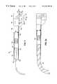
- FIG. 2is a partial cross-sectional top view of a handpiece in accordance with another embodiment of the invention, for use with the system of FIG. 1;
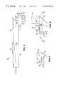
- FIG. 2 ais a partial cross-sectional top view of a handpiece wherein an optical fiber is provided within the handpiece for transferring light to a camera;
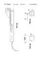
- FIG. 3is a side view of the handpiece of FIG. 2;
- FIG. 4is a front view of the distal portion of the handpiece 50 of the view of FIG. 3;
- FIG. 5is an enlarged front view of the distal portion of the handpiece of FIG. 3, positioned over a tooth of interest;
- FIG. 6 ais a side view of the handle separated from the handpiece
- FIGS. 6 b - 6 care each top views of two mouthpieces, which are mirror images of each other, for imaging all of the teeth of the mouth;
- FIGS. 7 a , 8 a and 9 aare top views of the handpiece, with its illumination section rotated to the left, in an intermediate position and rotated to the right;
- FIGS. 7 b , 8 b and 9 bshow the different views of the tooth by the camera, when the illumination section is in the positions of FIGS. 7 a , 8 a and 9 a , respectively;
- FIGS. 7 c , 8 c and 9 cshow the position of the second mirror with respect to the tooth when the illumination section is in the positions of FIGS. 7 a , 8 a and 9 a , respectively;
- FIG. 10is a cross-sectional view of FIG. 5 taken along line 10 — 10 , showing the relation between the prongs, the tooth of interest, and the adjacent teeth;
- FIG. 11is a cross-sectional view of the tooth of interest and adjacent teeth taken along line 11 — 11 in FIG. 10, showing the prongs and the horizontal plate in cross-section to further illustrate their position with respect to the teeth;
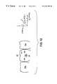
- FIG. 12is a coordinate system established with respect to the principal surfaces of the tooth of interest and showing reference points on the tooth;
- FIG. 13is a side view of another embodiment of the handpiece, for intra-oral recording of at least a portion of the mouth;
- FIG. 14is a flow chart of a method of controlling image acquisition parameters according to one embodiment of the present invention.
- FIG. 15is a schematic representation of the laboratory apparatus used to demonstrate the present invention.
- FIGS. 16 a - 16 fare a series of lingual and labial images of a tooth obtained with the laboratory apparatus of FIG. 15, each having an inset showing the angle of illumination and reception with respect to the tooth;
- FIG. 17 ais a direction matrix used in the wavelet segmentation of the tooth of interest
- FIG. 17 billustrates the translation of the angle of the x and y components to the direction matrix of FIG. 17 a;
- FIG. 18is a flow chart of a preferred wavelet segmentation procedure used in the present invention.
- FIGS. 19 a- 19 care a series of images showing an unprocessed image, and corresponding wavelet amplitude and wavelet phase representations of the unprocessed image, respectively, at different levels of wavelet transformation;
- FIG. 20 ais a series of images showing the effect of changes in wavelength on the images resulting from the wavelet representation
- FIG. 20 bis a graph of line scans across a lesion at the positions indicated by thin white lines in the three left panels in FIG. 20 a;
- FIG. 21is a flow chart of a preferred pattern matching procedure used in the present invention.
- FIG. 22 aare representations of modulus maxima in the wavelet magnitude representation of a tooth at levels 1-3 as indicated, for a DIFOTITM image;
- FIG. 22 bshows the boundary resulting from the segmentation of the images of FIG. 22 a
- FIG. 22 cshows the longest chain in the level 2 wavelet representation of the tooth in FIG. 22 b , at various light intensities;
- FIG. 23 ais a 3-dimensional plot of NCC vs. wavelet resolution (Level) vs. relative light intensity (Intensity) for pattern matching in the wavelet domain in accordance with the procedure of FIG. 21;
- FIG. 23 bis a plot of the standard deviation of the NCC values at the same grid points as in FIG. 23 a;
- FIG. 24 ais a series of images in wavelet magnitude representations, which were compared pairwise by computing the NCCs including an original image, an image with its intensity reduced by 30% and an image with its intensity reduced and with an artifact added;
- FIG. 24 bis a 3-dimensional plot of NCC vs. intensity and resolution, comparing the original image of FIG. 24 a with the intensity reduced image of FIG. 24 a ;
- FIG. 24 cis a 3-dimensional plot of NCC vs. intensity and resolution, showing the sensitivity to the simulated “lesion” structure of FIG. 24 a in the wavelet coefficient domain.
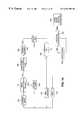
- FIG. 1schematically illustrates the principal components of a system 10 for imaging teeth in accordance with one embodiment of the present invention.
- the preferred embodiment of the system 10is referred to as a digital imaging fiber optic transillumination system (“DIFOTITM”).
- the system 10includes a source of illumination 11 which provides light to a handpiece 12 via an optical fiber or optical fiber bundle 14 .
- the handpiece 12has an output portion 16 from which light exits the handpiece 12 for illuminating a tooth 18 under examination, and an image input portion 20 for receiving light passing through the tooth.
- the output portion 16 and image input portion 20 of the handpiece 12define a region therebetween for receiving the tooth 18 .
- a preferred handpiece in accordance with the present inventionis described, below.
- the image plane of an electronic camera 24may be optically coupled to the image input portion 20 of the handpiece 12 through a separate optical fiber or fiber optic bundle 23 .
- the camerais a digital electronic camera having a charge-coupled-device (CCD) imaging array coupled to the optical fiber 23 .
- CCDcharge-coupled-device
- the CCDmay be located within the handpiece 12 as well, as discussed with respect to the embodiment of FIG. 2.
- a CCDis preferred because of its high signal-to-noise ratio and its direct generation of digital signals for immediate processing.
- An intra-oral cameracould also be positioned in the mouth, adjacent the side of the tooth opposite the side being illuminated. Alternatively, a video camera may be used and the video images subsequently digitized.
- the camera 24has an output for providing the images to a computer 26 .
- the computer 26is connected to a monitor 28 , such as a cathode ray tube (CRT) or liquid crystal display monitor.
- a keyboard 30 , a mouse 32 , a foot control 34 and/or a hand control 36are preferably connected to the computer 26 for inputting data and controlling the computer 26 , as discussed further, below.
- a hard-copy terminalsuch as a printer 38 is preferably provided connected to the computer 26 , as well.
- the hand control 36is preferably provided on the handle 22 of the handpiece 12 .
- the computer 26preferably has at least a 40 MHz clock speed and 16 megabytes of random access memory.
- An i486 Personal Computer, or its equivalent,may be used, for example. More advanced processors may be used, as well.
- the monitor 28can be a standard 14 inch monitor with gray scale format, for example.
- the illuminator source 11is a high intensity light source, such as a 24-watt metal halide short arc lamp.
- the intensity of the lampis preferably controlled by an adjustable, stabilized power supply.
- a suitable lampis an EXP0794 from Welch Allyn Corp., Lighting Products Division, Skaneateles Falls, N.Y. 13153, for example.
- a 50 watt version of the EXPO794may be used, as well.
- Other high intensity light sourcessuch as a small laser, a laser diode, a light emitting diode (“LED”), or a miniature light bulb, for example, may also be used to provide light for illuminating the tooth through the optical fiber 14 or directly by being positioned within the handpiece 12 .
- Interference filtersare preferably provided to define one or more selectable spectral bands of illumination.
- the filtersmay be provided on a filter wheel (not shown), for example.
- Four wavelength bandsare preferred, centered at 500 nm, 600 nm, 700 nm and white light.
- the power supply of the illuminator source 11 and the filter wheelare preferably coupled to the computer 26 so that the intensity and wavelength of the light can be adjusted. Other methods of adjusting the intensity of the light, such as through filters, may be used as well.
- Different wavelength bandsprovide different contrasts, which have been found to improve the identification of caries or other conditions.
- Adjustment of the intensity of the light illuminating the toothis advantageous because the varying thickness and density of different types of teeth, require different degrees of light intensity for optimal illumination and analysis.
- the intensity of lightcan be adjusted to avoid saturation of the CCD.
- the intensityis continuously adjustable over a range.
- the optical fibers 14 and 26can each be a single fiber with an aperture on the order of 1 mm or less, for example.
- the fiber used in laboratory demonstrationshad a 0.365 mm aperture, 0.22-NA.
- a multi-fiber bundle with a 3 mm aperture, for example,may be used, as well.
- the fiber 26should be an image preserving fiber or bundle.
- the fibercan be a autoclavable part or it can be provided with a thin, disposable, plastic sheath. Preferably, less than the entire side of the tooth is illuminated, to avoid reception of light passing around the tooth. Such light does not provide useful information.
- the camera 24may be a Toshiba 1 ⁇ 2′′ Model IK-541P-A high resolution CCD (720 ⁇ 570 pixels), equipped with a 23 mm Schneider f/1.4 Xenoplan lens and an extender for reducing the field of view (“FOV”), for example.
- the image calibration scalewas 43 pixels/mm over a 11.5 mm FOV. Smaller cameras are available, such as Toshiba's 1 ⁇ 3′′ IK-LTM42A Camera.
- a video cameramay also be used, in which case the video image would need to be digitized prior to its being provided to the computer processor.
- the printer 38may be a low cost, hard copy printer, such as a commercially available 600 dots per inch (dpi) laser printer, for example.
- Outputmay also be provided in pseudocolor at a resolution that is compatible with existing inexpensive color inkjet printers, such as 360 ⁇ 720 or 720 ⁇ 720 dpi. With either type of output, hardcopies can be generated at any time from stored image files.
- An auxiliary storage device 26 asuch as a floppy disc drive, a tape drive, ZIP drive, JAZ drive, or WORM drive, is preferably coupled to the computer 26 for storage of the images.
- FIG. 2is a partial cross-sectional top view of a handpiece 50 in accordance with another embodiment of the invention, for use with the system of FIG. 1 .
- FIG. 3is a side view of the handpiece 50 of FIG. 2
- FIG. 4is a front view of the distal portion of the handpiece 50 of the view of FIG. 3 .
- the handpiece 50preferably comprises two separable parts, a handle 52 and a mouthpiece 54 .
- FIG. 6 ais a side view of the handle 52 separated from the mouthpiece 54 .
- FIGS. 6 b and 6 care each top views of two mouthpieces 54 a , 5 b , respectively, which enable imaging all of the teeth of the mouth.
- FIG. 6 benables imaging of the buccal surfaces of the teeth in the upper right and lower left quadrants and the lingual surfaces of teeth in the lower right and upper left quadrants, as viewed by the operator.
- the mouthpiece 54 b of FIG. 6 cwhich is a mirror image of the mouthpiece 54 a of FIG. 6 b , enables imaging of the lingual surfaces of teeth in the lower right and upper left quadrants.
- the handle 52is received within a tubular portion 56 of the mouthpiece 54 .
- the outer diameter of the handle 52 and the inner diameter of the tubular portion 54are dimensioned to provide a tight fit.
- the handle 52has a slightly inwardly tapered portion at its distal end for engaging the inner surface of the tubular portion 54 .
- a detent mechanismsuch as a releasable clip 57 may be provided in the handle 52 for engaging a protrusion 58 in the tubular portion 56 , shown in FIGS. 6 b and 6 c , to secure the handle to the mouthpiece 54 . While described as tubular, the mouthpiece 54 and the handle 52 can have other shapes.
- the optical fiber or bundle 14shown in FIG. 1, has a section 14 a extending through the handle 52 (shown in FIG. 2 ), which is coupled to a section 14 b extending through a rear portion of the tubular portion 56 .
- the section 14 bexits the tubular portion 54 near its front end.
- An illumination section 60is provided, preferably pivotally coupled to the front end of the tubular portion 56 .
- a pin 62extends from a block 64 attached to or integral with the side of the front end of the tubular portion 56 , for attachment to the illumination section 60 , as shown in FIG. 4 .
- the front of the section 14 b of the optical fiber 14enters the illumination section 60 through a hole 60 a .
- the output of the section 14 a and the input of the section 14 beach has a lens 61 .
- the lenses 61are aligned when the two sections are connected, as is known in the art.
- There are two sections 14 a in the handle 52for accommodating each of the optical fiber sections 14 b of each mouthpiece 54 a , 54 b (shown in FIG. 6 a ).
- the illumination section 60includes a first mirror 66 positioned opposite the output 69 of the optical fiber 14 b , at an angle of 135° with respect to the longitudinal axis of the optical fiber 14 b .
- the mirror and portion of the optical fiber 14 b within the illumination section 60are shown in phantom in FIG. 2 .
- an LED, a small laser, a laser diode or a miniature light bulbmay also be used to illuminate the tooth.
- Those sourcescould provide illumination through the optical fiber 14 , they could be positioned adjacent the first mirror 66 , or they could be positioned to directly illuminate the tooth, dispensing with the need for the first mirror 66 .
- the illuminationis directed at or near the center of the lingual or buccal surface of the tooth.
- the illumination section 60includes a horizontal plate 68 which is connected to the block 64 by the pin 62 .
- a vertical wall 70depends from an edge of the horizontal plate 68 , as shown in FIGS. 3 and 4.
- the first mirror 66is provided within the vertical wall 70 .
- Front and rear vertical prongs 72 , 74extend from the edges of the vertical wall 70 , perpendicular to the vertical wall 70 and to the horizontal plate 68 .
- the prongs 72 , 74are shown in phantom in FIGS. 2 and 3, and in cross-section in FIG. 10 .
- the front prong 72is shown in FIG. 4 .
- the prongsmay have a height of 0.25 inches, a width of 0.15 inches and a thickness of 0.015 inches, for example.
- the tubular portion 56 of the mouthpiece 54includes a second mirror 76 depending from its front end in a plane angled 45° with respect to the plane of the horizontal plate 68 in FIG. 4.
- a third mirror 78is mounted within the front end of the tubular portion 56 , in a plane angled 45° with respect to the horizontal plate 68 in the view of FIG. 3 .
- the front endmay be square, elliptical or round.
- the first mirror 66is oriented to reflect light output from the optical fiber 14 b towards the second mirror 76 , which is oriented to reflect the light to the third mirror 78 , which is oriented to reflect the light down the tubular portion 56 .
- a tooth 18 under examinationis positioned between the first mirror 66 (in the vertical wall 70 ) and the second mirror 76 . It is understood that other mirror arrangements are possible.
- a spring loaded ball 82 or other such mechanismis preferably provided in the block 64 for engaging a depression or hole 65 in the horizontal plate 68 , to lock the illumination section 60 into an intermediate position with respect to the tubular portion 54 , as shown in FIGS. 4 and 5.
- the side of the horizontal plate 68 adjacent the tubular portion 56has two portions 84 , 86 which are angled away from the tubular portion 56 to allow for rotation about the pin 62 .
- the two portions 84 , 86provide stopping surfaces limiting the degree of rotation of the tubular portion 56 of the mouthpiece 54 with respect to the illumination section 60 . 10° rotation in either direction is preferred. Three positions are therefore defined, an intermediate position where the hole is engaged, as shown in FIGS. 2 and 8 a , and two positions plus and minus 10° from the intermediate position, wherein the tubular portion is rotated with respect to the illumination section 60 , as shown in FIGS. 7 a and 9 a . Positions between the stop positions can be used, as well.
- the CCD 88 of the electronic camera 24is preferably located in the handle 52 of the handpiece 50 .
- the CCD 88is mounted to a printed circuit board 90 and a wire 91 for coupling the CCD 88 and circuit board 90 to the computer 26 .
- a lens assembly 92is provided for focusing the light reflected from the third mirror 78 , onto the CCD 88 . Two lenses are shown, as an example.
- the clip 57 and the protrusion 58are arranged such that when the protrusion 58 of the tubular portion 56 is positioned to be engaged by the clip 57 , the third mirror 78 is properly aligned with respect to the lens assembly 92 .
- the lens assembly 92could focus the light into the optical fiber or bundle 23 , which could transfer the light to the CCD camera 24 , as shown in FIG. 2 a.
- the handle 52 and mouthpiece 54may be easily molded of styrene, for example.
- the mirrorsmay be aluminized styrene, for example.
- the components of the mouthpiece 54particularly the mirrors 66 , 76 and 86 , are relatively inexpensive. It is preferred that they be disposed after use, avoiding the need to clean and sterilize the mouthpiece 54 for reuse.
- Expensive components of the handpiece 50such as the CCD 88 and lens assembly 92 are preferably part of the handle 52 , which is reused.
- FIG. 10is a cross-sectional view of FIG. 5 along line 10 — 10 , showing the relation between the prongs 72 , 74 , the tooth of interest 18 and the adjacent teeth 18 a , 18 b .
- the front prong 72is typically inserted between the tooth of interest 18 and the adjacent tooth 18 a such that the front prong 72 bears against the proximal surface of the tooth 18 .
- FIG. 11is a side view of the tooth 18 and adjacent teeth 18 a , 18 b , showing the prongs 72 , 74 and horizontal plate 68 in cross-section to further illustrate their position with respect to the teeth 18 , 18 a and 18 b . If the tooth 18 is wider than the interprong spacing, if an adjacent tooth is missing or there is no adjacent tooth, as in the case of the last molar, one or both prongs 72 , 74 can straddle the tooth of interest 18 .
- FIGS. 8 a , 7 a and 9 ashow the handpiece 50 in its intermediate position, rotated to the left and rotated to the right, respectively.
- FIGS. 8 b , 7 b and 9 bshow the different views of the tooth 18 by the camera, in each position.
- Line A in FIGS. 7 b , 8 b and 9 brepresents the image plane of the camera.
- FIGS. 7 c , 8 c and 9 cshow the position of the second mirror 76 with respect to the tooth 18 in each position, and examples of light rays impinging on the mirror 76 .
- the outlines of the teethare shown schematically in the Figures.
- the light rays shown schematically in FIGS. 7 c , 8 c and 9 cexperience multiple scattering as they pass through the tooth 18 . Not all the light rays are scattered as they are transmitted through the tooth.
- the first mirror 16 and optical fiber 14 bare also shown.
- the mouthpiece 54may also be readily adapted for imaging the tooth with respect to the occlusal or incisal surface of the tooth, while illuminating the buccal or lingual surface of the tooth.
- the handpiece 50may include a bend to facilitate convenient movement within the oral cavities.
- the handpiece 50 of this embodiment of the inventionenables the accurate reproducibility of six degrees of freedom associated with the image of a tooth of interest 18 , defined with reference to the coordinate system shown in FIG. 12 .
- the tooth 18is depicted in relation to two adjacent teeth in FIG. 12, the coordinate system also applies to a single tooth in isolation.
- Translationsare described in a right-handed Cartesian x-y-z system, in which the z-axis proceeds into the x-y plane of the figure.
- the x-y planeis tangent to the lingual or buccal surface, whichever is closer to the observer, at point 95 .
- Positions along the y-axisare defined relative to an apical point 96 , which is located on the occlusal or incisal surface of the tooth 18 .
- Positions along the x-axisare defined relative to a margin of the tooth 18 , which is defined by the outermost point at the tooth, such as point 97 . If the outermost point is obscured by an adjacent tooth, the margin is defined by a reference line drawn through a pair of points within the tooth 18 and adjacent to the neighboring tooth 18 a such as 97 and 99 .
- Rotationsare described by roll, pitch and yaw angles, defined as follows: The roll axis is identical to the z-axis, so that roll angles are denoted by ⁇ z .
- Pitch angles ⁇ xare taken about an axis defined by points located on opposite margins of the tooth 18 such as 98 and 99 .
- Yaw angles ⁇ yare taken about the y-axis, defined by points 97 and 99 , as described above.
- the vertical wall itselfcan be used to fix the position of the mouthpiece 54 with respect to the z axis.
- the handpiece of the present inventionthereby enables the mouthpiece 54 to be precisely placed in essentially the same position with respect to the same tooth at a later time, enabling reliable examination of the tooth and comparisons with prior images of the same tooth taken at different times. Such comparisons are useful for monitoring changes in the condition of the tooth.
- the second prongis particularly preferred if such comparisons are to be made.
- the system of the present inventioncan also be used to illuminate and record part or all of a patient's mouth. Such images are often used for patient instruction and orientation.
- the handpiece 50 of FIG. 2can be adapted for such intra-oral recording by use of a different mouthpiece.
- An appropriate mouthpiece 540is shown in FIG. 13, connected to the handle 52 .
- the mouthpiece 540includes two optical fibers 542 , 544 , whose outputs are at the front end of the mouthpiece, to illuminate the mouth.
- a window 546receives the light reflected from the teeth.
- a mirror behind the window 546angled 45° with respect to the surface of the window, reflects the light towards the lens assembly 92 , which focuses the light onto the CCD 88 , as described with respect to FIG. 2 .
- the handle 52 of the handpiece 540is the same as described above.
- a separate camera and handpiececould be used.
- a separate cameracould be preferable because a different type of camera may be found to be more suited for each procedure. For example, a black and white camera may be found preferable for imaging a tooth while a color camera may be found preferable for intra-oral recording.
- a suitable color intra-oral camerais a Vistacom from Air Techniques, Inc., Hicksville, N.Y., for example.
- the CCD camera 24produces a digitized electronic image which is transferred to the computer 26 , which causes a digital image to be displayed on the monitor 28 , providing visual feedback in real time to the operator.
- the foot control 34is preferably provided to enable the operator to control such actions as capturing an image for storage to disk without having to release his or her hands from the handle 22 or from the patient's mouth. Such a function could be provided through the hand control 36 coupled to the handle 22 , as well.
- the quality of the displayed imagemay be judged subjectively by the operator for its perceived utility for diagnosis and the image can be adjusted, if necessary.
- the operatorcan adjust the intensity and wavelength of the illumination, and other imaging parameters such as exposure time, through the keyboard 30 , the mouse 32 or the hand control 36 , until the image quality is satisfactory.
- the computer 26can also automatically control certain imaging parameters, such as the intensity of the light, as discussed further, below.
- the operatormay also select a region of interest (“ROI”) in the displayed image by dragging the mouse 32 , for example.
- ROIregion of interest
- the operatorcan also select the level of digital magnification of the ROI through the keyboard 30 or the mouse 32 .
- the operatormay also override the computer control of the imaging process, such as the computer's control of the intensity of the light.
- the overridecan be provided on the hand control 36 and/or the foot control 34 , for example.
- Image display on the monitor 28 or by the optional printer 38facilitate comparison with other imaging modalities, if desired.
- imaging modalitiesinclude digitized dental x-ray films, digital radiographs, reflection-photographic images from an intraoral camera, or previously taken images.
- FIG. 14is a flow chart of a method of controlling the acquisition and processing of images in accordance with the preferred embodiment of the present invention, wherein the operator has the ability to observe processed images in near real time.
- An operatorcan capture a desired image of a tooth under examination at step 100 .
- the electronic representation of the captured image of the toothis referred to as the “current image.”
- the imageis analyzed by the computer software at step 102 to determine whether the maximum image intensity is within a predetermined range.
- the upper limit of the rangeis defined by the saturation level of the pixels of the image.
- the lower limit of the rangeis a predetermined threshold value. Saturated pixels, which would show up as fully white on the monitor 28 , do not provide the contrast resolution necessary for caries detection.
- the saturation levelcorresponds to a gray level of 255 in the 8-bit representation.
- a practical lower limit of the rangeis about 240. If there are any pixels at the saturation level, the appropriate control is adjusted by the computer 26 to reduce the intensity of the illuminator source 11 at step 104 . Similarly, if the maximum gray level in the current image is below the lower limit, the intensity control is adjusted by the computer 26 to increase the intensity of the illuminator source 11 until the maximum gray level in the image exceeds the lower limit. If the CCD photodetector saturation level is 1023 in a 10-bit representation, the corresponding range would be greater than about 950 and less than about 1023. Steps 100 - 104 are repeated until the maximum gray level in the image is less than 255 and greater than 240 in an 8-bit representation.
- Overall image brightnessmay also be adjusted by the operator based on his observation of the image on the monitor.
- the operatorcan override the intensity set by the software, if desired.
- a linear map of the gray levels in the image to a fixed, standard range desired for subsequent image processingis provided in step 106 .
- the linear map of gray levelswill typically correspond to a “stretch” of the initial intensities spanning the range of from 10, for example, to between about 240 to 255, into gray levels that span a standard range, 0-255 in the preferred embodiment.
- the standard range of 0-255is applicable, even if the raw data from the CCD photodetector 88 are represented by a greater number of bits, such as 10 bits, because currently, almost all image processing software only employs the most significant 8 bits of the signal. While specifically discussed with application to a CCD 18 in the preferred embodiment, feedback control of intensity would be useful with any electronic camera, whether the images are digitized or not, and such intensity control is a feature of the present invention.
- the operatorexamines the image displayed on the monitor 28 for local variations in image brightness that are atypical of normal teeth and that represent a possible lesion, in step 108 . If no such atypical regions are found, the operator can decide whether to change the position of image acquisition or change the wavelength of illumination at step 110 .
- the image acquisition position with respect to the toothcan be changed by rotating the handpiece 12 about the pivot pin 62 from the intermediate position to either of the stop surfaces 84 , 86 , or any position between the stop surfaces, by slightly moving the handpiece 12 coaxially about the tooth 18 under examination at step 12 . See FIGS. 7 a , 8 a , 9 a .
- the handpiece 12can be moved over another tooth at step 112 , as well.
- the wavelengthcan be changed by advancing the filter wheel, for example, through either the mouse 32 , the keyboard 30 , hand control 36 or foot control 34 , at step 114 .
- the new imagebecomes the “current image” of step 100 and is evaluated at steps 102 - 104 , as described above. Steps 108 - 114 are repeated until the image display contains a region of inhomogeneity that is suggestive of a possible lesion.
- the operatorselects a ROI over the relevant portion of the current image in step 116 , and then determines whether the image of the selected region is adequate for diagnosis, in step 118 .
- the ROIis preferably analyzed by image processing software, in step 120 , to improve its suitability for diagnosis.
- image processingis described in more detail, below.
- the operatordecides whether the clinical information available in the ROI is adequate for diagnosis, at step 118 . If the operator signals via the keyboard 30 or mouse 32 , or the other modes of control discussed above, that the image is adequate, the image is stored, along with ancillary data, in the storage medium associated with the computer 26 , in step 122 .
- Ancillary datainclude control parameters associated with the image, which is preferably automatically entered by the computer 26 , and any recorded annotations such as the dentist's diagnosis, the date of the procedure, or name of the patient, which the operator may enter at the keyboard 30 .
- Hard copies of images selected by the usermay be optionally output, either immediately or at a convenient later time, by the printer 38 .
- the digital image processing conducted at step 120provides visually enhanced representations of variations in the image that help the dentist diagnose the condition of the tooth.
- several optionsare available.
- digital zooms into and out of the ROIwavelet amplitude and phase-representations, iso-intensity contours and line scan profiles, may be provided and selected.
- Digital zooms into the ROImagnify the image.
- Digital zooms out of the ROIenable the operator to view the area surrounding the ROI, as well as enabling selection of a different ROI.
- Iso-intensity contoursmay assist in identifying local gradients which are characteristic of caries. Different intensity levels can be represented by different colors to further enhance the image visualization.
- Line scan profilesmay also be provided, which can serve to indicate certain asymmetries characteristic of the presence of caries.
- Multiresolution wavelet amplitude representations of the gray-level imagesprovide the operator with bandpass-filtered visualizations that serve to enhance edge contrasts. “Chains” of wavelet amplitude maxima are preferably used to provide image segmentation. Displays of wavelet phase representations are preferably provided to help visualize tooth surface and texture information. For example, rugate structures in the region of dental enamel tend to correspond to pitted surfaces. Wavelet amplitude and phase representations provide contrast enhancement and quantitative measures of differences between sound and carious tissues are preferably provided as well. Wavelet signal analysis is discussed further, below.
- the preferred embodiment of the present inventionpermits the operator to display on the monitor 28 one or more computer-calculated numerical measures of selected properties of the image which can assist the dentist in interpretation. Examples of such measures are average and peak values over the region of interest of the image contrast and its spatial gradient.
- Image pattern matching software techniquesare also, therefore, preferably provided for analyzing the images both in the gray-level, spatial domain and in the wavelet coefficient domain, to assist in monitoring such changes, which is also discussed further, below.
- FIG. 15 ais a schematic representation of the laboratory apparatus 500 . Images obtained with this apparatus are referred to as “DIFOTITM images”.
- Illuminationwas provided by a low-voltage 21-Watt metal-halide, short-arc lamp 502 whose intensity was controlled by an adjustable, stabilized power supply 504 .
- Illumination optics(not shown) provided a collimated region for insertion of interference filters 506 which defined the spectral band. Six filters were used between 450 and 700 nm, in steps of 50 nm.
- the lamp 502was coupled to a flexible light guide 508 for delivery of illumination to the target tooth 510 .
- Two light guides of different fiber sizeswere used: a 0.22 NA single fiber (0.365 mm aperture) and a multi-fiber bundle (3 mm aperture). Both guides provided sufficient illumination to acquire transillumination images with the narrow-band interference filters in place.
- the fiberswere fitted with nonreflecting shrouds, and mounted on a machinist's height gauge for positioning in all three directions (x,y,z) and for determining the angle between the imaging direction and the normal to the tooth.
- the specimen teethwere attached with plasticine to a precision rotation table 512 , which was mounted on a translation stage fastened to a lab jack, permitting angular and translational positioning of the specimen tooth.
- An imaging camera 514was positioned on the side of the tooth 510 opposite the light guide 508 .
- the imaging camera 514was connected to an i486 PC computer 516 , which processed and stored the images. Image analysis was implemented by software routines written in C++ programming language, such as those discussed below.
- a video monitor 518was connected to the computer 516 .
- the imaging camera 514was a Toshiba 1 ⁇ 2′′570 ⁇ high-resolution CCD (720 ⁇ 570 pixels), equipped with a 23-mm Schneider ⁇ /1.4 Xenoplan lens and an extender for reducing the field-of-view (FOV).
- the aperture and focuswere adjustable.
- the image calibration scalewas 43 pixels/mm over a 11.5-mm FOV.
- the relative efficacy of DIFOTITM and radiological imaging for the diagnosis of carieswas compared by analyzing 50 teeth which had been set in modeling stone and preserved in 10% buffered formalin.
- the teethincluded 15 incisors, 8 canines, 12 premolars and 14 molars, with and without caries.
- Each toothwas subjected to visual inspection under 4 ⁇ magnification, explorer and, where warranted, histological section, by two experts, to determine whether caries was present in each tooth.
- the consensus of these expertsserved as the standard for the evaluations of DIFOTITM and radiological performance.
- FIGS. 16 a - 16 fare examples of such images taken with the apparatus of FIG. 15 .
- FIGS. 16 a - 16 care lingual views and FIGS. 16 d - 16 f are labial views, respectively, of the same tooth at different angles of illumination and directions of view. The illumination was coaxial with the direction of view, as indicated in each figure by the inset.
- the dentistswere asked to determine the presence or absence of caries and the location of the caries relative to the tooth surfaces.
- the diagnosis based on the DIFOTITM images and the x-ray imageswere compared to the diagnosis of the experts.
- the sensitivity, or ability to correctly identify carious tissue, and the specificity, or ability to correctly identify healthy tissue,were evaluated.
- the sensitivity of DIFOTITMwas found to be superior to that of x-ray.
- the sensitivitywas twice as high in identifying approximal caries, three times as high in identifying occlusal caries and ten times as high in identifying smooth surface caries.
- the specificity of DIFOTITMwas comparable to that of x-ray. Certain of the DIFOTITM images indicated the presence of incipient and recurring caries while the corresponding x-ray images did not. Radiology, in contrast, has less lingual/facial differential.
- a two-dimensional waveletcan be seen as a collection of spatial filters in image processing or as a family of basis functions in mathematical representations.
- a rescaled prototype functionperforms the signal analysis at different resolution levels, such that in the wavelet transform domain, there is information about scale, position and frequency content.
- Waveletsare localized in both space and frequency. They have proven to be very useful in image compression and in applications where the images are statistically nonstationary.
- Wavelet representationis discussed in S. Mallat, S. Zhong, “Characterization of signals from multiscale edges,” IEEE Transactions on Pattern Analysis and Machine Intelligence”, Vol. 7, No. 7, pp. 710-732, July, 1992; and S. Mallat, S. Zhong, “Singularity detection and processing with wavelets”, IEEE Transactions on Information Theory, Vol. 38, No. 2, pp. 617-643, March 1992, for example.
- wavelet representations of imagesare available.
- a wavelet maxima representation methodwhich can be used both for image compression and for feature analysis and extraction, is preferred.
- Mallat's wavelets for image compressionwhich have been very successful in detecting boundaries between tissues with different x-ray transmissions, are particularly preferred. See, for example, Mallat, S., “A theory for multiresolution signal decomposition: The wavelet representation, IEEE Transactions on Pattern Recognition and Machine Intelligence, Vol. 11, No. 7, pp. 674-693 June 1989, which is incorporated by reference herein.
- Wavelet representationshave not been used in dental imaging applications such as DIFOTITM, where the presence and location of inhomogeneities in the image due to changes in tooth structure must be determined in the presence of multiple scattering of the transmitted light.
- the multiresolution wavelet representationprovides a hierarchical framework for the interpretation of image information.
- the details of the imagegenerally characterize different physical structures of the scene.
- Different objects in a scenehave signatures in the wavelet representation which differ from each other and from noise. Since the edges of an object propagate across scales in a specific manner, the shape can be extracted from its wavelet representation.
- the details at each resolutionare calculated by filtering the original image with the difference of two low-pass filters, or with a bandpass filter which is generated by the wavelet prototype.
- the waveletuses information weighted over 2 pixels in each direction.
- the wavelet transformhas two gradient-like components, W 1 f(2 j ,x,y), W 2 f(2 j ,x,y). These components can be interpreted as the two coordinates of the gradient vector of the image smoothed with the scaling filter at scale 2 j .
- the local maxima of the modulus of this filtered gradientcorrespond to the edges of the image at the scale 2 j .
- the preferred method of tooth image segmentationis based on looking for the “longest” chain among the chained maxima at each level in the wavelet domain. Since there generally is an edge discontinuity at the enamel border of a directly illuminated tooth, past which little light is transmitted to neighboring teeth, the boundary of the tooth under examination produces the longest chain. Consequently, the intensity at the boundaries of the neighboring teeth is almost never as high as at the boundary of the tooth being examined. It is noted that because the enamel is generally well illuminated, it is very unusual for the boundary defined by the longest chain to have branches. Since selecting the longest chain does not require either a global or a local threshold, the segmentation result is relatively invariant to the brightness of the illumination source.
- Segmentation results at different levelsare not expected to be identical, because resolution degradation occurs in computing at higher levels of the wavelet representation corresponding to coarser scales. Nevertheless, such differences do not affect the repeatability of segmentation, as long as the segmentation is always done at the same level.
- the DIFOTITM imageis first subjected to a fast dyadic discrete wavelet transformation in the redundant discrete wavelet representation (“RDWT”).
- RDWTas used herein is defined below:
- Equation 1is an extension in two dimensions of the one dimensional example of Aldroubi, Akram, et al., Wavelets in Medicine and Biology, CRC Press, Inc. (1996), pp. 17-18.
- the “low-high” and “high-low” gradient-like components of the representationare then selected.
- the “low-high” componentacts as a low pass filter of the x coordinate and a high pass filter of the y coordinate.
- the “high-low” componentacts as a high pass filter of the x coordinate and a low pass filter of the y coordinate.
- the transformed positionis denoted by (x′,y′) and the shorthand “high-low” and “low-high” notation below, is employed:
- ⁇ m (x) and ⁇ m (y)are biorthogonal bi-splines and ⁇ m (x) and ⁇ m (y) are their respective spatial derivatives.
- the measure of coefficient magnitudeis the root-sum-square of the “low-high” and “high-low” components:
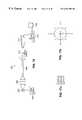
- the computed directionsare then discretized to one of the eight values indicated on the matrix in FIG. 17 a , wherein the numbers 0 through 7 correspond to the ⁇ directions shown in the diagram in FIG. 17 b.
- FIG. 18is a flow chart of a preferred procedure.
- the DIFOTI image 200is subjected to the fast dyadic discrete wavelet transformation in the redundant discrete wavelet representation in accordance with Equation 1.
- a starting node for the segmentation boundaryis located in step 206 . This may be done by the operator, who can choose any point on the display that clearly lies on the desired boundary. Alternatively, a default position on the tooth boundary is selected by the algorithm by proceeding from the intra-oral background towards the tooth boundary at its occlusal or incisal surface.
- Equation 4It is then determined whether the coefficient magnitude at the selected node is a maximum using Equation 4, in step 210 .
- the maximum magnitudeis defined as the largest magnitude over the matrix in FIG. 17 a.
- next node((node+1) mod 8), is the maximum at step 214 . If not, then it is determined whether the prior node ((node ⁇ 1) mod 8) is the maximum in step 212 . Because directions are chosen from the discrete set of eight, numbered 0 through 7 in FIG. 17 a , the selections of the next node are denoted as “modulo 8” in the flow chart. As the program advances to each node, the operator can observe the generation of the boundary curve on the image, and override the computed boundary, if necessary.
- the programwill either select the next node on the curve ((node+1) mod 8) to be a maximum-amplitude point, or will select a point lying along the computed direction of the boundary curve to be a maximum, where the maximum amplitude and computed direction are determined via Equations 3 and 4, above, in step 216 .
- Which procedure the program will followmay be determined by the operator prior to the session.
- step 216it is then determined whether the boundary is complete in step 218 .
- the boundaryis complete when the generated curve returns to its starting point or node. If the boundary is complete, the routine is exited at step 220 . If it is not, then the routine returns to step 208 , and steps 208 - 216 are repeated.
- the method of segmentation represented in FIG. 18has been implemented in software written in the C++ programming language, and executed on an IBM-compatible PC for transillumination images obtained with the laboratory apparatus of FIG. 15 .
- the applicable routines implementing the procedures of FIG. 18follow this description of the invention.
- FIG. 19 ais an unprocessed image obtained white light.
- FIGS. 19 b and 19 care different levels of wavelet amplitude representations and wavelet phase representations, respectively, of FIG. 19 a .
- the top imageis at level 1 and the bottom image is at level 3.
- the borders associated with rapid changes in the local image intensityare clearly evident in the amplitude representations of FIG. 19 b .
- Near the tooth surface, these representationstend to correlate with the borders between carious and normal tissue.
- the directions of local gradientsare manifest in the phase representation, where the presence of frank caries (indicated by darker regions in the unprocessed images that correlate with the presence of frank caries) give the appearance of deep craters, which may be useful for clinical visualization, as shown in FIG.
- FIG. 19 cDifferent levels of clinical detail can be extracted from wavelet components of different spatial resolutions.
- An example of the texture of the tooth surface facing the cameracan be visualized in the phase representation of FIG. 19 c , which indicates a rugate structure, corresponding to a pitted enamel surface.
- FIG. 20 ashows the effect of changes in wavelength on the images resulting from wavelet representation.
- the right-hand portion of FIG. 20 ashows a raw DIFOTITM image obtained at 500 nm.
- the left-hand imagesare in wavelet magnitude representation and were obtained at 500 nm, 700 nm, and in white light, as indicated.
- the contours between carious and noncarious tissueare clear. In this representation, the area of the lesion is uniformly dark at 500 nm.
- the wavelet representation in the sound tissue surrounding the cariesindicates nonuniform intensity associated with light viewed through nonuniform anatomical structures.
- the wavelet representationillustrates that the 500 nm illumination was absorbed uniformly by the frank caries, whereas some of the 700 nn (and white-light) illumination was nonuniformly attenuated by the caries lesion.
- FIG. 20 bis a graph of line scans across the lesion at the positions indicated by thin white lines in the three left panels in FIG. 20 a .
- These line scansrepresent the wavelet amplitude variation profiles across the lesion image, for white light, and for narrow-band illumination at 700 nm and 500 nm, as indicated.
- the amplitudes in the 500 nm imageare negligibly small in the lesion area (pixels 17 through 38 ), and there is greater variability inside the lesion at 700 nm than with white light.
- the highest contrastis provided at 500 nm.
- current images of a toothare compared to earlier images of the same tooth, to monitor for detrimental or ameliorative changes over time.
- a representationwhich is insensitive to overall light intensity variation but is able to enhance structural changes in segmented teeth. This is achieved in the preferred embodiment by the wavelet maxima representation, which can compare images with intensity differences of up to about 25%. If the intensity is adjusted to a value which varies by more than about 25% from the intensity used in the prior image, the operator can override the intensity adjustment and set a desired intensity in the region of interest, as discussed above.
- position and orientationare computed from the gray-level images.
- the first moment of intensitythe centroid of the tooth under examination, is used to estimate the position of the tooth in the field of view.
- the orientation of the toothis estimated from the second moment of intensity, the moment-of-least-inertia. See, for example, B. Klauss, P. Horn, “Robot Vision”, Cambridge, Mass., MIT Press, 1986, pp. 48-53, p. 175. Since both these moment quantities are relatively insensitive to small local changes in the spatial domain, the representation, location and orientation of the tooth are estimated in the spatial domain, prior to pattern matching.
- the dyadic wavelet transformwas applied, and the wavelet coefficients for five resolution levels were stored. The coefficients were linearly expanded into full, 0-255 range.
- the dominant, source-intensity-sensitive signalswere first dilated and filtered out.
- the gray level image of a tooth of interest in the spatial domainwas segmented from the background using the longest modulus maxima chain at the finest level of wavelet representation, followed by an estimation of its location and orientation.
- the wavelet magnitude representation of each image at each levelwas also segmented by using the boundaries at that level to remove possible contribution from background such as a light tip, a gum or neighboring teeth. Each segmented wavelet magnitude representation of the “compared” image was then translated and rotated with respect to the “original” image.
- FIG. 21is a flow chart of a preferred monitoring procedure employing images to monitor the changes in the tooth over time, such as changes in a mineralization front indicative of caries status.
- a current image including a particular tooth of interestis represented by box 300 and an image including the same tooth, obtained under similar conditions in a prior clinical session, is represented by box 302 .
- both imagesare subjected to the same sequence of steps, as indicated by the parallel paths or data streams in the flow chart, since results of some or all intermediate steps in the processing sequence can be stored between clinical sessions, it is not necessary that the steps in these parallel paths take place simultaneously.
- processing stepsare performed directly on the gray levels of the recorded image. Such steps are indicated in FIG. 21 by dotted lines as occurring in the “spatial domain.” Other processing steps, indicated by solid lines, take place in the wavelet coefficient domain. The combination of processing in both the wavelet and spatial domains has been found to provide more robust, accurate results.
- the wavelet coefficient domainis entered for each image 300 , 302 through the wavelet transformation at steps 304 , 304 a, which may correspond to step 202 in FIG. 18 .
- wavelet transformationssuch as a non-redundant wavelet transformation
- Non-redundant wavelet transformationmay be preferred here because it encompasses fewer pixels, speeding computations.
- Steps 304 , 304 aindicate three or more levels. While Level 1 represents the scale that carries the finest detail in the image, it has been found that levels 2 or 3 provide better results, as discussed below.
- Coefficient magnitude representations of the wavelet-transformed images computed in steps 304 , 304 aare segmented in steps 306 , 306 a . Steps 306 , 306 a correspond to steps 204 - 220 of the flow chart of FIG. 18 .
- the image representations resulting from the wavelet segmentation steps 306 , 306 ainclude portions that correspond to adjacent teeth and gums and which are not needed for caries diagnosis. Therefore, the portions of the image outside the tooth of interest are preferably eliminated from the image in the spatial domain in steps 308 , 308 a , 310 and 310 a .
- the same segmentation maskis applied to the image in the spatial domain in steps 310 and 310 a and to its coefficient magnitude representation in steps 308 , 308 a . The latter are referred to as the segmented magnitude representations.
- the first and second moments of the gray level distributions in each of the segmented images in the spatial domainare also computed in steps 310 , 310 a .
- the centroids of these distributionsare located through the first moments and the principal axes of the inertia tensor are determined through the second moments, also in steps 310 , 310 a .
- the coordinates governing the relative position of the centroids in the two imagesare then adjusted to shift them into coincidence, in step 312 .
- One of the two imagesis then rotated with respect to the other to bring the principal axes of their gray level distributions into coincidence, also in step 312 .
- the current image 300is shifted and rotated into coincidence with the prior image 302 . It may be more advantageous to shift and/or rotate the prior image into coincidence with the current image, as is known in the art.
- NCCNormalized cross correlation
- ( ⁇ overscore (x) ⁇ , ⁇ overscore (y) ⁇ )represents a computed shifting factor (translation) of one image object relative to another, that is applied after rotation of the detected (and segmented) objects as described at step 312 ; and the indicator function b(x,y) is “1” (one) when I(x,y) belongs to the segmented object, “0” (zero) otherwise.
- This equationis slightly modified from that of Hang, to suit the present application. It has been found that NCC, whose numerator is linear in image differences, is less sensitive to roundoff errors in intermediate computer calculations than other techniques that require calculating the squares of such differences. Roundoff errors can be significant when the DIFOTITM images of the same tooth, with at most slight differences, are being compared.
- the result of this pattern matching processis a matching score in step 316 , which is a numerical value whose deviation from a reference value such as 1.00 serves to indicate the degree of mismatch between the two patterns under comparison, derived in step 314 .
- a value less than approximately 0.90indicates sufficient change in the tooth to warrant further examination of the state of mineralization of the tooth.
- FIG. 21A monitoring procedure similar to that of FIG. 21 was also implemented in software as described with respect to FIG. 18, using DIFOTITM images obtained with the laboratory apparatus of FIG. 15 .
- the applicable routines implementing the procedures of FIG. 21also follow the description of the invention.
- FIG. 22 ashows a typical modulus maxima chaining representation in levels 1-3 for a DIFOTITM image at 91.1% of initial intensity (nominally 9.1 mW).
- the supporting spatial-frequency ranges in both the x- and y- directionswere: n 0 ⁇ 23 ⁇ m and ⁇ 0 ⁇ 43 mm ⁇ 1 at level 1; n 0 ⁇ 46 ⁇ m and ⁇ 0 ⁇ 21 mm ⁇ 1 at level 2; n 0 ⁇ 92 ⁇ m and ⁇ 0 ⁇ 10 mm ⁇ 1 at level 3; physical interpretation is based on the camera spatial resolution (43 pixels/mm). The results demonstrated successful segmentation of all teeth over the field of view, without exception.
- FIG. 22 ashows a typical modulus maxima chaining representation in levels 1-3 for a DIFOTITM image at 91.1% of initial intensity (nominally 9.1 mW).
- the supporting spatial-frequency ranges in both the x- and y- directionswere:
- FIG. 22 bshows the stability of the boundary resulting from the segmentation of the images of FIGS. 22 a , using the longest chain in any one of these three levels of the wavelet representation.
- FIG. 22 cshows the boundary resulting from the longest chain in the wavelet representations of the same tooth at various light intensities at level 2 wherein the image at the original intensity, nominally 9.1 mW, is compared with images for which the intensity is reduced to 80.7% and 71.9% of the nominal value.
- the segmentation results in the wavelet domainare repeatable within the range of illumination source intensity variations tested.
- wavelet segmentation of an imagemay depend on the level (resolution) used, segmentation at the same level is always repeatable, as illustrated in FIG. 22 c . Repeatability of segmentation is an essential prerequisite to monitoring the status of a tooth over time.
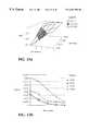
- FIG. 23 aThe results of pattern matching in the wavelet coefficient domain are summarized by the 3-dimensional plots of NCCs vs. wavelet resolution (Level) and vs. relative light intensity (Intensity) in FIG. 23 a .
- Each point in the plot in FIG. 23 arepresents an average of the NCCs for 40 independent cases for images obtained with the laboratory apparatus of FIG. 15 .
- FIG. 23 bcontains a plot of the standard deviation of the NCC values at the same grid points as in FIG. 23 a .
- the NCCdecreases by less than about 10%.
- the pattern matching methodis therefore robust with respect to intensity changes. This robustness is independent of light wavelength or type of tooth.
- NCCis higher in the wavelet representation at coarser resolution, because the effects of noise are reduced by the low pass filter effect of the wavelet transformation, pattern matching is preferably performed at higher levels.
- the second levelcan be used.
- the standard deviations computed at this level, shown in FIG. 23 bare ⁇ 1%. If the light source intensity is less well controlled, the pattern matching should be done at lower resolution, with the concomitant risk of insensitivity to small changes.
- the brightest region in FIG. 23 arepresenting NCCs over 90%, is within the preferred signal-to-noise trade-off range.
- Pattern matching ability in the wavelet-magnitude representationwas tested by calculating the NCC between “original”, images and “compared” images containing light absorption artifacts that simulated the presence of lesions.
- Wavelet representations at various levelsshow high sensitivity to changes occurring in the segmented lesion, relatively independent of illumination source intensity changes less than about 20%.
- An example of such wavelet-magnitude representation pairsis shown in FIG. 24 a , in which the effect of the absorption artifact is clearly visible in the right-most image.
- the 3-dimensional plots of NCC vs. intensity and resolution in FIGS. 24 b - 24 cshow the desired sensitivity in the wavelet coefficient domain to the simulated “lesion” structure. Comparison of FIGS.
Landscapes
- Health & Medical Sciences (AREA)
- Life Sciences & Earth Sciences (AREA)
- Surgery (AREA)
- Engineering & Computer Science (AREA)
- Medical Informatics (AREA)
- General Health & Medical Sciences (AREA)
- Pathology (AREA)
- Veterinary Medicine (AREA)
- Public Health (AREA)
- Biophysics (AREA)
- Biomedical Technology (AREA)
- Heart & Thoracic Surgery (AREA)
- Physics & Mathematics (AREA)
- Molecular Biology (AREA)
- Animal Behavior & Ethology (AREA)
- Nuclear Medicine, Radiotherapy & Molecular Imaging (AREA)
- Radiology & Medical Imaging (AREA)
- Dentistry (AREA)
- Oral & Maxillofacial Surgery (AREA)
- Optics & Photonics (AREA)
- Physiology (AREA)
- Computer Networks & Wireless Communication (AREA)
- Audiology, Speech & Language Pathology (AREA)
- Dental Tools And Instruments Or Auxiliary Dental Instruments (AREA)
- Endoscopes (AREA)
Abstract
Description

Claims (69)
Priority Applications (6)
| Application Number | Priority Date | Filing Date | Title |
|---|---|---|---|
| US08/778,001US6201880B1 (en) | 1996-12-31 | 1996-12-31 | Method and apparatus for electronically imaging a tooth through transillumination by light |
| EP97953471AEP0950228B1 (en) | 1996-12-31 | 1997-12-31 | Apparatus for electronically imaging a tooth through transillumination by light |
| AU57211/98AAU5721198A (en) | 1996-12-31 | 1997-12-31 | Method and apparatus for electronically imaging a tooth through transilluminaionby light |
| DE69729216TDE69729216T2 (en) | 1996-12-31 | 1997-12-31 | DEVICE FOR THE ELECTRONIC REPRESENTATION OF A TOOTH BY TRANSILLUMINATION BY LIGHT |
| PCT/US1997/023953WO1998029050A2 (en) | 1996-12-31 | 1997-12-31 | Method and apparatus for electronically imaging a tooth through transilluminaion by light |
| US09/467,345US6714657B1 (en) | 1996-12-31 | 1999-12-20 | Apparatus for holding optical instruments in a reproducible position with respect to teeth |
Applications Claiming Priority (1)
| Application Number | Priority Date | Filing Date | Title |
|---|---|---|---|
| US08/778,001US6201880B1 (en) | 1996-12-31 | 1996-12-31 | Method and apparatus for electronically imaging a tooth through transillumination by light |
Related Child Applications (1)
| Application Number | Title | Priority Date | Filing Date |
|---|---|---|---|
| US09/467,345Continuation-In-PartUS6714657B1 (en) | 1996-12-31 | 1999-12-20 | Apparatus for holding optical instruments in a reproducible position with respect to teeth |
Publications (1)
| Publication Number | Publication Date |
|---|---|
| US6201880B1true US6201880B1 (en) | 2001-03-13 |
Family
ID=25111977
Family Applications (1)
| Application Number | Title | Priority Date | Filing Date |
|---|---|---|---|
| US08/778,001Expired - LifetimeUS6201880B1 (en) | 1996-12-31 | 1996-12-31 | Method and apparatus for electronically imaging a tooth through transillumination by light |
Country Status (5)
| Country | Link |
|---|---|
| US (1) | US6201880B1 (en) |
| EP (1) | EP0950228B1 (en) |
| AU (1) | AU5721198A (en) |
| DE (1) | DE69729216T2 (en) |
| WO (1) | WO1998029050A2 (en) |
Cited By (142)
| Publication number | Priority date | Publication date | Assignee | Title |
|---|---|---|---|---|
| US6276933B1 (en)* | 2000-03-21 | 2001-08-21 | Ivan Melnyk | Dental translucency analyzer and method |
| US6282359B1 (en)* | 1999-11-27 | 2001-08-28 | Electro Optical Sciences Inc. | Injection molded light pipe |
| US6341957B1 (en)* | 1999-11-27 | 2002-01-29 | Electro-Optical Sciences Inc. | Method of transillumination imaging of teeth |
| WO2002082820A1 (en)* | 2001-04-07 | 2002-10-17 | Dentsply International, Inc. | Dental video imaging system |
| US6542180B1 (en)* | 2000-01-07 | 2003-04-01 | Mitutoyo Corporation | Systems and methods for adjusting lighting of a part based on a plurality of selected regions of an image of the part |
| US20030156681A1 (en)* | 2002-02-15 | 2003-08-21 | Egidio Cianciosi | Dental imaging system and apparatus using IEEE 1394 protocol |
| US20030185450A1 (en)* | 2002-02-13 | 2003-10-02 | Garakani Arman M. | Method and apparatus for acquisition, compression, and characterization of spatiotemporal signals |
| US6672868B1 (en)* | 2001-11-23 | 2004-01-06 | Electro-Optical Sciences Inc. | Method of transillumination imaging of teeth |
| US20040219481A1 (en)* | 2003-05-02 | 2004-11-04 | Malin Leo J. | Method of adjusting a drill bushing for a dental implant |
| US20050026104A1 (en)* | 2003-07-28 | 2005-02-03 | Atsushi Takahashi | Dental mirror, and an intraoral camera system using the same |
| US20050084144A1 (en)* | 2002-01-16 | 2005-04-21 | Andrei Feldman | Oral implant template |
| US20050084816A1 (en)* | 2003-10-21 | 2005-04-21 | Mehdizadeh Bahman M. | Systems and methods for performing dental operations |
| US20050100333A1 (en)* | 2003-11-10 | 2005-05-12 | Ivoclar Vivadent Ag | Intra-oral camera and a method for using same |
| US20050100866A1 (en)* | 1999-07-23 | 2005-05-12 | Teraview Limited | Radiation probe and detecting tooth decay |
| WO2005013843A3 (en)* | 2003-08-08 | 2005-06-02 | Univeristy Of California | Near-infrared transillumination for the imaging of early dental decay |
| US6908307B2 (en) | 2003-02-03 | 2005-06-21 | Schick Technologies | Dental camera utilizing multiple lenses |
| US6958766B2 (en) | 2000-04-06 | 2005-10-25 | Gendex Corporation | Dental video imaging system |
| US20050255424A1 (en)* | 2004-05-14 | 2005-11-17 | Kaltenbach & Voigt Gmbh | Dental device for the investigation of the optical properties of tooth tissue |
| US20050254704A1 (en)* | 2002-07-26 | 2005-11-17 | Olympus Corporation | Image processing system |
| US20050287490A1 (en)* | 2004-06-29 | 2005-12-29 | Therametric Technologies, Inc. | Handpiece for caries detection |
| US6997883B1 (en)* | 1997-04-07 | 2006-02-14 | Rainer Hahn | Diagnostic apparatus for determining the remineralization ability of tissue |
| US20060035195A1 (en)* | 2004-08-12 | 2006-02-16 | Electro Optical Sciences, Inc. | Method of transillumination of teeth |
| US20060152586A1 (en)* | 2002-07-26 | 2006-07-13 | Olympus Corporation | Image processing system |
| WO2006111730A1 (en)* | 2005-04-22 | 2006-10-26 | Single Use Surgical Limited | Disposable flexible endoscope |
| US20060251408A1 (en)* | 2004-01-23 | 2006-11-09 | Olympus Corporation | Image processing system and camera |
| US20060281045A1 (en)* | 2005-03-31 | 2006-12-14 | Perioimaging, Inc. | Ultrasonic periodontal, system and method of using |
| US20060293891A1 (en)* | 2005-06-22 | 2006-12-28 | Jan Pathuel | Biometric control systems and associated methods of use |
| US20070134615A1 (en)* | 2005-12-08 | 2007-06-14 | Lovely Peter S | Infrared dental imaging |
| US20070172101A1 (en)* | 2006-01-20 | 2007-07-26 | Kriveshko Ilya A | Superposition for visualization of three-dimensional data acquisition |
| US20080089588A1 (en)* | 2006-10-11 | 2008-04-17 | Seiko Epson Corporation | Rotation angle detection apparatus, and control method and control program of rotation angle detection apparatus |
| US20080248447A1 (en)* | 2005-08-29 | 2008-10-09 | Dentsply Canada Ltd. | Interproximal Tooth Defects Detection |
| US20080297611A1 (en)* | 2007-05-31 | 2008-12-04 | Microsoft Corporation | Computer-controlled lighting for video communication |
| US20090075228A1 (en)* | 2007-09-18 | 2009-03-19 | Olympus Corporation | Dental observation apparatus |
| US20090087811A1 (en)* | 2007-09-26 | 2009-04-02 | Degudent Gmbh | Method for measuring a body having at least one semitransparent layer |
| US20090214089A1 (en)* | 2008-02-27 | 2009-08-27 | Therametric Technologies, Inc. | System and Method for Data Analysis And Capture |
| US20100020165A1 (en)* | 2008-07-24 | 2010-01-28 | Apteryx, Inc. | Apparatus and methods for full-mouth intraoral image acquisition |
| US20100028296A1 (en)* | 2005-05-02 | 2010-02-04 | Chavez Raymond A | Use of cytokine-derived peptides in treatment of pain and neurodegenerative disease |
| US20100152871A1 (en)* | 2006-01-20 | 2010-06-17 | 3M Innovative Properties Company | Local enforcement of accuracy in fabricated models |
| NL2004154C2 (en)* | 2010-01-04 | 2011-07-05 | Elisabeth Wilhelmina Hendrika Laan | DEVICE AND METHOD FOR DETERMINING THE STATE OF A TOOTH, A DIAL OR ANOTHER BODY PART. |
| US8019801B1 (en)* | 2004-06-23 | 2011-09-13 | Mayo Foundation For Medical Education And Research | Techniques to rate the validity of multiple methods to process multi-dimensional data |
| WO2011140663A1 (en) | 2010-05-13 | 2011-11-17 | Quantum Dental Technologies Inc. | Method of processing and displaying oral health diagnostic data |
| US20120101343A1 (en)* | 2010-10-21 | 2012-04-26 | Duffy Thomas P | Medical imaging device |
| US20120122052A1 (en)* | 2010-11-11 | 2012-05-17 | Kaltenbach & Voigt Gmbh | Medical, in Particular Dental, Diagnostic Device Having Image Capture Means |
| EP2520221A1 (en)* | 2011-05-03 | 2012-11-07 | W & H Dentalwerk Bürmoos GmbH | Handle for a medical diagnosis device and medical diagnosis device |
| US20120288819A1 (en)* | 2011-05-09 | 2012-11-15 | E. Ron Burrell Dental Corporation | Dental imaging system with orientation detector |
| WO2013019405A1 (en)* | 2011-08-02 | 2013-02-07 | Carestream Health, Inc. | Adaptive illumination method and apparatus for dental shade matching |
| US20130108980A1 (en)* | 2010-07-15 | 2013-05-02 | Chris Leinweber | Intra-oral imager isolating device |
| US20130216971A1 (en)* | 2012-02-21 | 2013-08-22 | I Practice Marketing, LLC | Wireless intra-oral imaging system and method |
| US20140085449A1 (en)* | 2011-04-05 | 2014-03-27 | The Governing Council Of The University Of Toronto | Systems and methods for thermophotonic dynamic imaging |
| US20140093835A1 (en)* | 2012-09-28 | 2014-04-03 | Align Technology, Inc. | Estimating a surface texture of a tooth |
| US20140221843A1 (en)* | 2013-02-02 | 2014-08-07 | The Regents Of The University Of California | Near-infrared imaging for diagnosis of sinusitis |
| US20140227655A1 (en)* | 2013-02-12 | 2014-08-14 | Ormco Corporation | Integration of model data, surface data, and volumetric data |
| US8811774B1 (en)* | 2012-01-19 | 2014-08-19 | Pixelworks, Inc. | Super resolution using an interpretive scaler |
| EP2888992A1 (en)* | 2009-03-17 | 2015-07-01 | Kaltenbach & Voigt GmbH | Medical, in particular dental, diagnosis device with imaging means |
| WO2015178962A1 (en)* | 2014-05-23 | 2015-11-26 | Apollo Oral Scanner, LLC | Novel dental scanner device and system and methods of use |
| US20160220200A1 (en)* | 2015-01-30 | 2016-08-04 | Dental Imaging Technologies Corporation | Dental variation tracking and prediction |
| US9763827B2 (en) | 2013-04-30 | 2017-09-19 | Tear Film Innovations, Inc. | Systems and methods for the treatment of eye conditions |
| US20170347943A1 (en)* | 2016-06-03 | 2017-12-07 | The Regents Of The University Of California | Methods and apparatus for the assessment of gingival blood flow |
| RU2657940C1 (en)* | 2017-05-02 | 2018-06-18 | Арт фотоникс ГмбХ | Method for diagnosis of maxillary sinus diseases of a patient and device for implementation thereof |
| US10052171B1 (en)* | 2017-04-07 | 2018-08-21 | Naif A. Almalki | Intraoral multifunctional dental tool |
| US10092449B2 (en) | 2013-04-30 | 2018-10-09 | Tear Film Innovations, Inc. | Systems and methods for the treatment of eye conditions |
| US10123706B2 (en) | 2016-07-27 | 2018-11-13 | Align Technology, Inc. | Intraoral scanner with dental diagnostics capabilities |
| US10130445B2 (en) | 2014-09-19 | 2018-11-20 | Align Technology, Inc. | Arch expanding appliance |
| US10248883B2 (en) | 2015-08-20 | 2019-04-02 | Align Technology, Inc. | Photograph-based assessment of dental treatments and procedures |
| WO2019082452A1 (en)* | 2017-10-24 | 2019-05-02 | ソニー株式会社 | Dental image acquiring device and dental image acquiring method |
| US10327693B2 (en)* | 2017-07-07 | 2019-06-25 | 3M Innovative Properties Company | Tools for tracking the gum line and displaying periodontal measurements using intra-oral 3D scans |
| US10327872B2 (en) | 2014-08-15 | 2019-06-25 | Align Technology, Inc. | Field curvature model for confocal imaging apparatus with curved focal surface |
| US10383705B2 (en) | 2016-06-17 | 2019-08-20 | Align Technology, Inc. | Orthodontic appliance performance monitor |
| US10390913B2 (en) | 2018-01-26 | 2019-08-27 | Align Technology, Inc. | Diagnostic intraoral scanning |
| US10413234B2 (en)* | 2016-04-06 | 2019-09-17 | At&T Intellectual Property I, L.P. | Connected dental device |
| US10413385B2 (en) | 2004-02-27 | 2019-09-17 | Align Technology, Inc. | Method and system for providing dynamic orthodontic assessment and treatment profiles |
| US10421152B2 (en) | 2011-09-21 | 2019-09-24 | Align Technology, Inc. | Laser cutting |
| CN110313037A (en)* | 2017-02-17 | 2019-10-08 | 阿莱恩技术有限公司 | Longitudinal Analysis and Visualization in Limited Precision Systems |
| US10449016B2 (en) | 2014-09-19 | 2019-10-22 | Align Technology, Inc. | Arch adjustment appliance |
| US10456043B2 (en) | 2017-01-12 | 2019-10-29 | Align Technology, Inc. | Compact confocal dental scanning apparatus |
| US10463243B2 (en)* | 2017-03-16 | 2019-11-05 | Carestream Dental Technology Topco Limited | Structured light generation for intraoral 3D camera using 1D MEMS scanning |
| US10470847B2 (en) | 2016-06-17 | 2019-11-12 | Align Technology, Inc. | Intraoral appliances with sensing |
| US10504386B2 (en) | 2015-01-27 | 2019-12-10 | Align Technology, Inc. | Training method and system for oral-cavity-imaging-and-modeling equipment |
| US10507087B2 (en) | 2016-07-27 | 2019-12-17 | Align Technology, Inc. | Methods and apparatuses for forming a three-dimensional volumetric model of a subject's teeth |
| US10512672B2 (en) | 2013-07-18 | 2019-12-24 | Xalud Therapeutics, Inc. | Methods for the treatment of inflammatory joint disease |
| US10517482B2 (en) | 2017-07-27 | 2019-12-31 | Align Technology, Inc. | Optical coherence tomography for orthodontic aligners |
| US10524881B2 (en) | 2010-04-30 | 2020-01-07 | Align Technology, Inc. | Patterned dental positioning appliance |
| US10537405B2 (en) | 2014-11-13 | 2020-01-21 | Align Technology, Inc. | Dental appliance with cavity for an unerupted or erupting tooth |
| US10543064B2 (en) | 2008-05-23 | 2020-01-28 | Align Technology, Inc. | Dental implant positioning |
| US10548700B2 (en) | 2016-12-16 | 2020-02-04 | Align Technology, Inc. | Dental appliance etch template |
| US10595966B2 (en) | 2016-11-04 | 2020-03-24 | Align Technology, Inc. | Methods and apparatuses for dental images |
| US10610332B2 (en) | 2012-05-22 | 2020-04-07 | Align Technology, Inc. | Adjustment of tooth position in a virtual dental model |
| US10613515B2 (en) | 2017-03-31 | 2020-04-07 | Align Technology, Inc. | Orthodontic appliances including at least partially un-erupted teeth and method of forming them |
| US10610106B2 (en) | 2014-05-07 | 2020-04-07 | Align Technology, Inc. | Identification of areas of interest during intraoral scans |
| US10639134B2 (en) | 2017-06-26 | 2020-05-05 | Align Technology, Inc. | Biosensor performance indicator for intraoral appliances |
| US10758321B2 (en) | 2008-05-23 | 2020-09-01 | Align Technology, Inc. | Smile designer |
| US10772506B2 (en) | 2014-07-07 | 2020-09-15 | Align Technology, Inc. | Apparatus for dental confocal imaging |
| US10779718B2 (en) | 2017-02-13 | 2020-09-22 | Align Technology, Inc. | Cheek retractor and mobile device holder |
| US10813720B2 (en) | 2017-10-05 | 2020-10-27 | Align Technology, Inc. | Interproximal reduction templates |
| US10842601B2 (en) | 2008-06-12 | 2020-11-24 | Align Technology, Inc. | Dental appliance |
| US10849506B2 (en) | 2016-04-13 | 2020-12-01 | Inspektor Research Systems B.V. | Bi-frequency dental examination |
| US10885521B2 (en) | 2017-07-17 | 2021-01-05 | Align Technology, Inc. | Method and apparatuses for interactive ordering of dental aligners |
| US10893918B2 (en) | 2012-03-01 | 2021-01-19 | Align Technology, Inc. | Determining a dental treatment difficulty |
| US20210022593A1 (en)* | 2019-07-24 | 2021-01-28 | United States Of America As Rep By Sec Of The Navy | Photoplethysmography Imaging (PPGI)-Based Pulp Vitality Test |
| US10919209B2 (en) | 2009-08-13 | 2021-02-16 | Align Technology, Inc. | Method of forming a dental appliance |
| US10932890B1 (en) | 2019-11-14 | 2021-03-02 | Pearl Inc. | Enhanced techniques for determination of dental margins in intraoral scans |
| US10974063B2 (en) | 2016-06-30 | 2021-04-13 | Alcon Inc. | Light therapy for eyelash growth |
| US10980613B2 (en) | 2017-12-29 | 2021-04-20 | Align Technology, Inc. | Augmented reality enhancements for dental practitioners |
| US10993783B2 (en) | 2016-12-02 | 2021-05-04 | Align Technology, Inc. | Methods and apparatuses for customizing a rapid palatal expander |
| US11026831B2 (en) | 2016-12-02 | 2021-06-08 | Align Technology, Inc. | Dental appliance features for speech enhancement |
| US11026768B2 (en) | 1998-10-08 | 2021-06-08 | Align Technology, Inc. | Dental appliance reinforcement |
| US11045283B2 (en) | 2017-06-09 | 2021-06-29 | Align Technology, Inc. | Palatal expander with skeletal anchorage devices |
| US11083545B2 (en) | 2009-03-19 | 2021-08-10 | Align Technology, Inc. | Dental wire attachment |
| US11096763B2 (en) | 2017-11-01 | 2021-08-24 | Align Technology, Inc. | Automatic treatment planning |
| US11103330B2 (en) | 2015-12-09 | 2021-08-31 | Align Technology, Inc. | Dental attachment placement structure |
| US11116605B2 (en) | 2017-08-15 | 2021-09-14 | Align Technology, Inc. | Buccal corridor assessment and computation |
| US11123156B2 (en) | 2017-08-17 | 2021-09-21 | Align Technology, Inc. | Dental appliance compliance monitoring |
| US11213368B2 (en) | 2008-03-25 | 2022-01-04 | Align Technology, Inc. | Reconstruction of non-visible part of tooth |
| US11219506B2 (en) | 2017-11-30 | 2022-01-11 | Align Technology, Inc. | Sensors for monitoring oral appliances |
| US20220039659A1 (en)* | 2018-12-20 | 2022-02-10 | Empident Gmbh | Method and system for oral hygiene inspection |
| US11273011B2 (en) | 2016-12-02 | 2022-03-15 | Align Technology, Inc. | Palatal expanders and methods of expanding a palate |
| US11337773B2 (en) | 2015-12-15 | 2022-05-24 | Emudent Technologies Pty Ltd | Dental apparatus |
| US11376101B2 (en) | 2016-12-02 | 2022-07-05 | Align Technology, Inc. | Force control, stop mechanism, regulating structure of removable arch adjustment appliance |
| US11419702B2 (en) | 2017-07-21 | 2022-08-23 | Align Technology, Inc. | Palatal contour anchorage |
| US11426259B2 (en) | 2012-02-02 | 2022-08-30 | Align Technology, Inc. | Identifying forces on a tooth |
| US11432908B2 (en) | 2017-12-15 | 2022-09-06 | Align Technology, Inc. | Closed loop adaptive orthodontic treatment methods and apparatuses |
| US11436191B2 (en) | 2007-11-08 | 2022-09-06 | Align Technology, Inc. | Systems and methods for anonymizing patent images in relation to a clinical data file |
| US20220313064A1 (en)* | 2019-07-04 | 2022-10-06 | Scivita Medical Technology Co., Ltd. | Endoscope |
| US11471252B2 (en) | 2008-10-08 | 2022-10-18 | Align Technology, Inc. | Dental positioning appliance having mesh portion |
| US11534268B2 (en) | 2017-10-27 | 2022-12-27 | Align Technology, Inc. | Alternative bite adjustment structures |
| US11534974B2 (en) | 2017-11-17 | 2022-12-27 | Align Technology, Inc. | Customized fabrication of orthodontic retainers based on patient anatomy |
| US11554000B2 (en) | 2015-11-12 | 2023-01-17 | Align Technology, Inc. | Dental attachment formation structure |
| US11564777B2 (en) | 2018-04-11 | 2023-01-31 | Align Technology, Inc. | Releasable palatal expanders |
| US11576752B2 (en) | 2017-10-31 | 2023-02-14 | Align Technology, Inc. | Dental appliance having selective occlusal loading and controlled intercuspation |
| US11596502B2 (en) | 2015-12-09 | 2023-03-07 | Align Technology, Inc. | Dental attachment placement structure |
| US11612454B2 (en) | 2010-04-30 | 2023-03-28 | Align Technology, Inc. | Individualized orthodontic treatment index |
| US11633268B2 (en) | 2017-07-27 | 2023-04-25 | Align Technology, Inc. | Tooth shading, transparency and glazing |
| US11717384B2 (en) | 2007-05-25 | 2023-08-08 | Align Technology, Inc. | Dental appliance with eruption tabs |
| US11823376B2 (en) | 2018-05-16 | 2023-11-21 | Benevis Informatics, Llc | Systems and methods for review of computer-aided detection of pathology in images |
| US20240041570A1 (en)* | 2020-12-17 | 2024-02-08 | Dyson Technology Limited | Oral treatment device |
| US11931222B2 (en) | 2015-11-12 | 2024-03-19 | Align Technology, Inc. | Dental attachment formation structures |
| US11937991B2 (en) | 2018-03-27 | 2024-03-26 | Align Technology, Inc. | Dental attachment placement structure |
| US11996181B2 (en) | 2017-06-16 | 2024-05-28 | Align Technology, Inc. | Automatic detection of tooth type and eruption status |
| US12090020B2 (en) | 2017-03-27 | 2024-09-17 | Align Technology, Inc. | Apparatuses and methods assisting in dental therapies |
| US12171575B2 (en) | 2017-10-04 | 2024-12-24 | Align Technology, Inc. | Intraoral systems and methods for sampling soft-tissue |
| US12274597B2 (en) | 2017-08-11 | 2025-04-15 | Align Technology, Inc. | Dental attachment template tray systems |
| US12318247B1 (en)* | 2024-09-04 | 2025-06-03 | Mloptic Corp. | Early dental caries detection system and method |
Families Citing this family (7)
| Publication number | Priority date | Publication date | Assignee | Title |
|---|---|---|---|---|
| JP2001275964A (en)* | 2000-03-29 | 2001-10-09 | Matsushita Electric Ind Co Ltd | Video scope |
| EP1210907A1 (en)* | 2000-12-04 | 2002-06-05 | Fuji Photo Film Co., Ltd. | Fluorescent image obtaining apparatus |
| DE102006041020B4 (en)* | 2006-09-01 | 2015-01-22 | Kaltenbach & Voigt Gmbh | System for transilluminating teeth and head piece therefor |
| DE102006062998B3 (en) | 2006-09-01 | 2019-06-27 | Kaltenbach & Voigt Gmbh | System for transilluminating teeth |
| DE102006063000B3 (en) | 2006-09-01 | 2019-06-27 | Kaltenbach & Voigt Gmbh | System for transilluminating teeth |
| US8792688B2 (en)* | 2007-03-01 | 2014-07-29 | Titan Medical Inc. | Methods, systems and devices for three dimensional input and control methods and systems based thereon |
| KR102573669B1 (en) | 2017-06-21 | 2023-09-04 | 코닌클리케 필립스 엔.브이. | Method and device for early caries detection |
Citations (57)
| Publication number | Priority date | Publication date | Assignee | Title |
|---|---|---|---|---|
| US2840070A (en) | 1956-03-09 | 1958-06-24 | Benjamin F Tofflemire | Light-directing surgical retractor instrument |
| GB922994A (en) | 1960-07-13 | 1963-04-03 | Alonzo Roy Trevallon Barnes | Improvements in or relating to dental instruments |
| US3152587A (en) | 1960-03-31 | 1964-10-13 | Hellige & Co Gmbh F | Medical photometric apparatus |
| DE2208902A1 (en) | 1972-02-25 | 1973-08-30 | Ritter Ag | DEVICE FOR OPTICAL IMAGE TRANSFER FOR DENTAL PURPOSES |
| DE2308554A1 (en) | 1973-02-21 | 1974-08-22 | Nath Guenther | DENTAL TREATMENT DEVICE FOR CARIES PROPHYLAXIS |
| DE2505798A1 (en) | 1975-02-12 | 1976-08-26 | Hans K Schneider | Video magnifier for dental treatment - using endoscope with video camera and monitor |
| US4074306A (en) | 1975-07-28 | 1978-02-14 | Olympus Optical Co., Ltd. | Endoscope utilizing color television and fiber optics techniques |
| US4077399A (en) | 1976-08-03 | 1978-03-07 | New Research And Development Laboratories, Inc. | Cranial transillumination device |
| JPS5345081A (en) | 1976-10-05 | 1978-04-22 | Canon Kk | Endscope containing solid state camera |
| US4162618A (en) | 1977-07-25 | 1979-07-31 | Koyo Seiko Company Limited | Device for rolls in high speed rolling mills and the like |
| US4168882A (en) | 1975-04-30 | 1979-09-25 | The Secretary Of State For Social Services In Her Britannic Majesty's Government Of The United Kingdom Of Great Britain And Northern Ireland | Optical systems |
| US4184175A (en)* | 1977-02-09 | 1980-01-15 | The Procter & Gamble Company | Method of and apparatus for optically detecting anomalous subsurface structure in translucent articles |
| US4265227A (en) | 1979-10-03 | 1981-05-05 | The Hospital And Welfare Board Of Hillsborough County | Infant extremity positioner and illuminator |
| US4286602A (en) | 1979-06-20 | 1981-09-01 | Robert Guy | Transillumination diagnostic system |
| US4324546A (en) | 1979-09-12 | 1982-04-13 | Paul Heitlinger | Method for the manufacture of dentures and device for carrying out the method |
| DE3045162A1 (en) | 1980-12-01 | 1982-07-01 | Heitlinger, Paul, Dr., 6054 Rodgau | Probe for dental examination - has optic fibre cable and video camera |
| US4385344A (en) | 1980-08-29 | 1983-05-24 | Dentsply Research & Development Corp. | Visible light apparatus for curing photo-curable compositions |
| US4413278A (en) | 1981-10-05 | 1983-11-01 | Designs For Vision, Inc. | Optical coupling apparatus for coupling an arthoscope to a camera |
| DE3233410A1 (en) | 1982-09-09 | 1984-04-26 | Lercher, geb. Wellbrock, Ilse, 7201 Emmingen-Liptingen | Illumination for medical purposes |
| US4468197A (en)* | 1983-04-26 | 1984-08-28 | Wayne Provost | Apparatus and method for detecting cavities |
| EP0122537A1 (en) | 1983-04-11 | 1984-10-24 | Sumitomo Electric Industries Limited | Device for remote viewing |
| US4479499A (en) | 1982-01-29 | 1984-10-30 | Alfano Robert R | Method and apparatus for detecting the presence of caries in teeth using visible light |
| US4490433A (en) | 1982-05-24 | 1984-12-25 | Teijin Limited | Process for producing antistatic carpet |
| US4516195A (en) | 1983-12-28 | 1985-05-07 | Dentsply Research & Development Corp. | Multi-function dental operating light source |
| WO1985002101A1 (en) | 1983-11-08 | 1985-05-23 | Laserscope, Inc. | Endoscopic device having handle assembly and catheter assembly |
| US4539586A (en) | 1983-10-07 | 1985-09-03 | Welch Allyn Inc. | Connector module for video endoscopic system |
| US4575805A (en) | 1980-12-24 | 1986-03-11 | Moermann Werner H | Method and apparatus for the fabrication of custom-shaped implants |
| US4589846A (en) | 1982-09-29 | 1986-05-20 | Annoni Jerry D | Tooth transilluminating light holder |
| EP0184778A2 (en) | 1984-12-10 | 1986-06-18 | Opielab, Inc. | Protective endoscope sheath and method of installing same |
| US4601284A (en) | 1984-05-18 | 1986-07-22 | Fuji Photo Optical Co., Ltd. | Endoscope connecting system |
| JPS61190518A (en) | 1985-02-19 | 1986-08-25 | Asahi Glass Co Ltd | Production of polyurethane urea elastomer |
| US4608622A (en) | 1983-12-28 | 1986-08-26 | Dentsply Research & Development Corp. | Multi-function light source |
| US4639772A (en) | 1984-02-07 | 1987-01-27 | Circon Corporation | Focusable video camera for use with endoscopes |
| US4667229A (en) | 1984-05-18 | 1987-05-19 | Fuji Photo Optical Company, Ltd. | Color video endoscope system |
| GB2183058A (en) | 1985-10-24 | 1987-05-28 | Dentsply Ltd | Dental mirrors |
| FR2591094A1 (en) | 1985-12-09 | 1987-06-12 | Benaim Georges | Oral videoscope |
| US4727416A (en) | 1987-03-05 | 1988-02-23 | Fuji Optical Systems, Inc. | Electronic video dental camera |
| US4754328A (en) | 1984-01-03 | 1988-06-28 | Medical Dynamics, Inc. | Laser endoscope |
| US4759347A (en) | 1981-09-12 | 1988-07-26 | Fuji Photo Optical Company, Ltd. | Endoscope apparatus using solid state image pickup device |
| EP0282832A1 (en) | 1987-03-05 | 1988-09-21 | High-Tech Medical Instrumentation Inc. | Dental device for intraoral video imaging |
| WO1988007691A1 (en) | 1987-03-24 | 1988-10-06 | Raychem Corporation | Pin and socket fiber optic connector |
| JPS63267329A (en) | 1987-04-24 | 1988-11-04 | Olympus Optical Co Ltd | Dental endoscope |
| EP0296520A2 (en) | 1987-06-22 | 1988-12-28 | Dentsply International, Inc. | Recording perio probe |
| US4836782A (en) | 1983-05-06 | 1989-06-06 | Dentsply Research & Development Corp. | Method for providing direct cool beam incident light on dental target |
| US4836206A (en) | 1987-02-25 | 1989-06-06 | The United States Of America As Represented By The Department Of Health And Human Services | Method and device for determining viability of intact teeth |
| US4860094A (en) | 1987-03-10 | 1989-08-22 | Olympus Optical Co., Ltd. | Control apparatus for use with different types of endoscopes |
| US4915626A (en) | 1989-01-18 | 1990-04-10 | Lemmey Edgar S | Dental inspection and display apparatus |
| US4947245A (en) | 1988-05-23 | 1990-08-07 | Sumitomo Electric Industries, Ltd. | Image picking-up and processing apparatus |
| US5007837A (en) | 1987-03-26 | 1991-04-16 | Ellena | Differential photopolymerization process used for filling a dental cavity and a tool intended for its implementation |
| US5016098A (en) | 1987-03-05 | 1991-05-14 | Fuji Optical Systems, Incorporated | Electronic video dental camera |
| US5049070A (en) | 1990-01-09 | 1991-09-17 | High-Tech Medical Instrumentation, Inc. | Dental drill integral camera and optics |
| US5051823A (en) | 1988-01-28 | 1991-09-24 | Fuji Optical Systems, Inc. | Dental instrument including laser device and electronic video dental camera |
| US5052924A (en) | 1989-03-22 | 1991-10-01 | Berg Randy J | Fiberoptic imaging dental drill |
| US5115307A (en)* | 1987-03-05 | 1992-05-19 | Fuji Optical Systems | Electronic video dental camera |
| DE4307411A1 (en) | 1993-03-09 | 1994-09-15 | Mira Gmbh | Dental examination instrument |
| US5408992A (en) | 1993-11-05 | 1995-04-25 | British Technology Group Usa Inc. | Endoscopic device for intraoral use |
| US5583950A (en)* | 1992-09-16 | 1996-12-10 | Mikos, Ltd. | Method and apparatus for flash correlation |
Family Cites Families (1)
| Publication number | Priority date | Publication date | Assignee | Title |
|---|---|---|---|---|
| US4446197A (en) | 1982-07-23 | 1984-05-01 | The Goodyear Tire & Rubber Company | Ion beam deposition or etching re rubber-metal adhesion |
- 1996
- 1996-12-31USUS08/778,001patent/US6201880B1/ennot_activeExpired - Lifetime
- 1997
- 1997-12-31DEDE69729216Tpatent/DE69729216T2/ennot_activeExpired - Lifetime
- 1997-12-31EPEP97953471Apatent/EP0950228B1/ennot_activeExpired - Lifetime
- 1997-12-31AUAU57211/98Apatent/AU5721198A/ennot_activeAbandoned
- 1997-12-31WOPCT/US1997/023953patent/WO1998029050A2/enactiveIP Right Grant
Patent Citations (60)
| Publication number | Priority date | Publication date | Assignee | Title |
|---|---|---|---|---|
| US2840070A (en) | 1956-03-09 | 1958-06-24 | Benjamin F Tofflemire | Light-directing surgical retractor instrument |
| US3152587A (en) | 1960-03-31 | 1964-10-13 | Hellige & Co Gmbh F | Medical photometric apparatus |
| GB922994A (en) | 1960-07-13 | 1963-04-03 | Alonzo Roy Trevallon Barnes | Improvements in or relating to dental instruments |
| DE2208902A1 (en) | 1972-02-25 | 1973-08-30 | Ritter Ag | DEVICE FOR OPTICAL IMAGE TRANSFER FOR DENTAL PURPOSES |
| DE2308554A1 (en) | 1973-02-21 | 1974-08-22 | Nath Guenther | DENTAL TREATMENT DEVICE FOR CARIES PROPHYLAXIS |
| DE2505798A1 (en) | 1975-02-12 | 1976-08-26 | Hans K Schneider | Video magnifier for dental treatment - using endoscope with video camera and monitor |
| US4168882A (en) | 1975-04-30 | 1979-09-25 | The Secretary Of State For Social Services In Her Britannic Majesty's Government Of The United Kingdom Of Great Britain And Northern Ireland | Optical systems |
| US4074306A (en) | 1975-07-28 | 1978-02-14 | Olympus Optical Co., Ltd. | Endoscope utilizing color television and fiber optics techniques |
| US4077399A (en) | 1976-08-03 | 1978-03-07 | New Research And Development Laboratories, Inc. | Cranial transillumination device |
| JPS5345081A (en) | 1976-10-05 | 1978-04-22 | Canon Kk | Endscope containing solid state camera |
| US4184175A (en)* | 1977-02-09 | 1980-01-15 | The Procter & Gamble Company | Method of and apparatus for optically detecting anomalous subsurface structure in translucent articles |
| US4162618A (en) | 1977-07-25 | 1979-07-31 | Koyo Seiko Company Limited | Device for rolls in high speed rolling mills and the like |
| US4286602A (en) | 1979-06-20 | 1981-09-01 | Robert Guy | Transillumination diagnostic system |
| US4324546A (en) | 1979-09-12 | 1982-04-13 | Paul Heitlinger | Method for the manufacture of dentures and device for carrying out the method |
| US4265227A (en) | 1979-10-03 | 1981-05-05 | The Hospital And Welfare Board Of Hillsborough County | Infant extremity positioner and illuminator |
| US4385344A (en) | 1980-08-29 | 1983-05-24 | Dentsply Research & Development Corp. | Visible light apparatus for curing photo-curable compositions |
| DE3045162A1 (en) | 1980-12-01 | 1982-07-01 | Heitlinger, Paul, Dr., 6054 Rodgau | Probe for dental examination - has optic fibre cable and video camera |
| US4575805A (en) | 1980-12-24 | 1986-03-11 | Moermann Werner H | Method and apparatus for the fabrication of custom-shaped implants |
| US4759347A (en) | 1981-09-12 | 1988-07-26 | Fuji Photo Optical Company, Ltd. | Endoscope apparatus using solid state image pickup device |
| US4413278A (en) | 1981-10-05 | 1983-11-01 | Designs For Vision, Inc. | Optical coupling apparatus for coupling an arthoscope to a camera |
| US4479499A (en) | 1982-01-29 | 1984-10-30 | Alfano Robert R | Method and apparatus for detecting the presence of caries in teeth using visible light |
| US4490433A (en) | 1982-05-24 | 1984-12-25 | Teijin Limited | Process for producing antistatic carpet |
| DE3233410A1 (en) | 1982-09-09 | 1984-04-26 | Lercher, geb. Wellbrock, Ilse, 7201 Emmingen-Liptingen | Illumination for medical purposes |
| US4589846A (en) | 1982-09-29 | 1986-05-20 | Annoni Jerry D | Tooth transilluminating light holder |
| EP0122537A1 (en) | 1983-04-11 | 1984-10-24 | Sumitomo Electric Industries Limited | Device for remote viewing |
| US4468197A (en)* | 1983-04-26 | 1984-08-28 | Wayne Provost | Apparatus and method for detecting cavities |
| US4836782A (en) | 1983-05-06 | 1989-06-06 | Dentsply Research & Development Corp. | Method for providing direct cool beam incident light on dental target |
| US4539586B1 (en) | 1983-10-07 | 1991-12-17 | Welch Allyn Inc | |
| US4539586A (en) | 1983-10-07 | 1985-09-03 | Welch Allyn Inc. | Connector module for video endoscopic system |
| WO1985002101A1 (en) | 1983-11-08 | 1985-05-23 | Laserscope, Inc. | Endoscopic device having handle assembly and catheter assembly |
| US4608622A (en) | 1983-12-28 | 1986-08-26 | Dentsply Research & Development Corp. | Multi-function light source |
| US4516195A (en) | 1983-12-28 | 1985-05-07 | Dentsply Research & Development Corp. | Multi-function dental operating light source |
| US4754328A (en) | 1984-01-03 | 1988-06-28 | Medical Dynamics, Inc. | Laser endoscope |
| US4639772A (en) | 1984-02-07 | 1987-01-27 | Circon Corporation | Focusable video camera for use with endoscopes |
| US4601284A (en) | 1984-05-18 | 1986-07-22 | Fuji Photo Optical Co., Ltd. | Endoscope connecting system |
| US4667229A (en) | 1984-05-18 | 1987-05-19 | Fuji Photo Optical Company, Ltd. | Color video endoscope system |
| EP0184778A2 (en) | 1984-12-10 | 1986-06-18 | Opielab, Inc. | Protective endoscope sheath and method of installing same |
| JPS61190518A (en) | 1985-02-19 | 1986-08-25 | Asahi Glass Co Ltd | Production of polyurethane urea elastomer |
| GB2183058A (en) | 1985-10-24 | 1987-05-28 | Dentsply Ltd | Dental mirrors |
| FR2591094A1 (en) | 1985-12-09 | 1987-06-12 | Benaim Georges | Oral videoscope |
| US4836206A (en) | 1987-02-25 | 1989-06-06 | The United States Of America As Represented By The Department Of Health And Human Services | Method and device for determining viability of intact teeth |
| EP0282832A1 (en) | 1987-03-05 | 1988-09-21 | High-Tech Medical Instrumentation Inc. | Dental device for intraoral video imaging |
| US5429502A (en)* | 1987-03-05 | 1995-07-04 | Fuji Optical Systems, Inc. | Electronic video dental camera |
| US4727416A (en) | 1987-03-05 | 1988-02-23 | Fuji Optical Systems, Inc. | Electronic video dental camera |
| US4727416B1 (en) | 1987-03-05 | 1993-04-06 | Fuji Optical System Inc | |
| US5115307A (en)* | 1987-03-05 | 1992-05-19 | Fuji Optical Systems | Electronic video dental camera |
| US5016098A (en) | 1987-03-05 | 1991-05-14 | Fuji Optical Systems, Incorporated | Electronic video dental camera |
| US4860094A (en) | 1987-03-10 | 1989-08-22 | Olympus Optical Co., Ltd. | Control apparatus for use with different types of endoscopes |
| WO1988007691A1 (en) | 1987-03-24 | 1988-10-06 | Raychem Corporation | Pin and socket fiber optic connector |
| US5007837A (en) | 1987-03-26 | 1991-04-16 | Ellena | Differential photopolymerization process used for filling a dental cavity and a tool intended for its implementation |
| JPS63267329A (en) | 1987-04-24 | 1988-11-04 | Olympus Optical Co Ltd | Dental endoscope |
| EP0296520A2 (en) | 1987-06-22 | 1988-12-28 | Dentsply International, Inc. | Recording perio probe |
| US5051823A (en) | 1988-01-28 | 1991-09-24 | Fuji Optical Systems, Inc. | Dental instrument including laser device and electronic video dental camera |
| US4947245A (en) | 1988-05-23 | 1990-08-07 | Sumitomo Electric Industries, Ltd. | Image picking-up and processing apparatus |
| US4915626A (en) | 1989-01-18 | 1990-04-10 | Lemmey Edgar S | Dental inspection and display apparatus |
| US5052924A (en) | 1989-03-22 | 1991-10-01 | Berg Randy J | Fiberoptic imaging dental drill |
| US5049070A (en) | 1990-01-09 | 1991-09-17 | High-Tech Medical Instrumentation, Inc. | Dental drill integral camera and optics |
| US5583950A (en)* | 1992-09-16 | 1996-12-10 | Mikos, Ltd. | Method and apparatus for flash correlation |
| DE4307411A1 (en) | 1993-03-09 | 1994-09-15 | Mira Gmbh | Dental examination instrument |
| US5408992A (en) | 1993-11-05 | 1995-04-25 | British Technology Group Usa Inc. | Endoscopic device for intraoral use |
Non-Patent Citations (33)
| Title |
|---|
| "A comparison of bitewing radiography and interdental trans-illumination as adjuncts to the clinical identification of approximal caries in posterior teeth", A.D. Sidi et al., Diagnostic Aids, British Dental Journal, 1988. |
| "A Theory for Multiresolution Signal Decomposition: The Wavelet Representation", S. Mallat, IEEE Transactions on Pattern Analysis and Machine Intelligence, vol. 11, No. 7, Jul. 1989; pp. 674-692. |
| "Accuracy of Visual Inspection, Fiber-optic Transillumination, and Various Radiographic Image Modalities for the Detection of Occlusal Caries in Extracted Non-cavitated Teeth", A. Wenzel et al., J. Dent Res., 1992, pp. 1934-1937. |
| "Characterization of Signals from Multiscale Edges", S. Mallat et al., IEEE Transactions on Pattern Analysis and Machine Intelligence, vol. 14, No. 7, Jul. 1992; pp. 710-732. |
| "Comparison of fibre optic transillumination with clinical and radiographic caries diagnosis", K.W. Stephen et al., 1986; pp. 90-94. |
| "Diagnosis by Transillumination", W.J. Cameron, Fourth Edition, 1923, pp. 16-17. |
| "Diagnosis by Transillumination,", W.J. Cameron, Sixth Edition, Table of Contents, 1927, pp. 24-25. |
| "Digital Radiography", Clinical Research Associates Newsletter, vol. 19, Issue 5, May 1995; pp. 1-2. |
| "Discover The World of Demetron", An Advertising Brochure of Demetron Research Corporation, Danbury, Connecticut; 1983. |
| "Fiber Optic Lighting Systems: Their Role in Dentistry", J.L Bomba, Dental Clinics of North America, vol. 15, No. 1, Jan. 1971; pp. 197-218. |
| "Handbook of Visual Communications", H. Hang et al., Academic Press, 1995; pp. 156-158. |
| "Illumination of the oral cavity", R.C. Taylor et al., JADA, vol. 74, May 1967, pp. 1207-1209. |
| "Image Features From Phase Congruency", P. Kovesi, Technical Report 95/4, Department of Computer Science, The University of Western Australia, Jun. 1995; pp. 1-30. |
| "Image Features From Phase Congruency", P. Kovesi, University of Western Australia, Technical Report 95/4, Mar./Jun. 1995, pp. 1-30. |
| "Increased spatial resolution for light images of tissues-especially for teeth", A.O. Wist et al., SPIE, vol. 1894, pp. 52-63, 1993. |
| "Introduction to Statistical Pattern Recognition", K. Fukunaga, Academic Press, Inc., 1990; pp. 91-97, 124-125, 219-221. |
| "Optical Quantitation and Radiographic Diagnosis of Incipient Approximal Caries Lesions", E.H. Verdonschot et al., Clinical Science, Caries Res 1991; 25, pp. 359-364. |
| "Root caries", S. Liliasson, et al., The Telande Foundation, 1992, pp. 21-25. |
| "Singularity Detection and Processing with Wavelets", S. Mallat et al., IEEE Transactions on Information Theory, vol. 38, No. 2, Mar. 1992, p. 617-643. |
| "Singularity Detection and Processing with Wavelets", S. Mallat et al., IEEE Transactions on Information Theory, vol. 38, No. 2, Mar. 1992; pp. 617-643. |
| "The use of fiber optics transillumination for the detection of proximal caries", L.R. Manson-Hing, Dental Radiology, American Academy of Dental Radiology, Oral Surg., Dec. 1973, pp. 891-897. |
| "The Wavelet Transform, Time-Frequency Localization and Signal Analysis," I. Daubechies, IEEE Transactions on Information Theory, vol. 36, No. 5, Sep. 1990; pp. 961-1005. |
| "Transillumination in the Oral Cavity", G.R. Winter et al., Dental Digest, Mar. 1949, pp. 106-110. |
| "Transillumination of the oral cavity with use of fiber optics", J. Friedman et al., JADA, vol. 80, Apr. 1970, pp. 801-809. |
| "Using Computers to Diagnose and Plan Treatment of Approximal Caries Detected in Radiographs", R.C. Duncan et al., JADA, vol. 126, 1995, pp. 873-882. |
| "Wavelet Maxima Presentation", S. Mallat et al., Courant Institute of Mathematcial Sciences, pp. 206-284, 1989. |
| "Wavelets in medicine and biology", A. Aldroubi et al., Table of Contents, Preface, 1996. |
| Mallat, S., "Wavelet Maxima Representation", 1989, pp. 208-214.* |
| Robot Vision, B. Horn et al., The MIT PRess, 1991; pp. 48-53, 175. |
| Vaarkamp, S., "Propagation of Light Through Human Pental Enamal and Dentine," Journal of ORCA, 1995, pp. 8-13.* |
| Verdonschot, E.H., "Optical Quantitation and Radiographic Diagnosis of Incipient Approximal Caries Lesions", 1991, pp. 359-364.* |
| Wavelets and Applications, Y. Meyer, editor, Springer-Verlag NY 1992; pp. 207-284, Chapter entitled "Wavelet Maxima Representation" by S. Mallat et al. |
| Wavelets in Medicine and Biology, A. Aldroubi et al., CRC Press, Inc., 1996; pp. 11-18. |
Cited By (245)
| Publication number | Priority date | Publication date | Assignee | Title |
|---|---|---|---|---|
| US6997883B1 (en)* | 1997-04-07 | 2006-02-14 | Rainer Hahn | Diagnostic apparatus for determining the remineralization ability of tissue |
| US11026768B2 (en) | 1998-10-08 | 2021-06-08 | Align Technology, Inc. | Dental appliance reinforcement |
| US8027709B2 (en)* | 1999-07-23 | 2011-09-27 | Teraview Limited | Radiation probe and detecting tooth decay |
| US20050100866A1 (en)* | 1999-07-23 | 2005-05-12 | Teraview Limited | Radiation probe and detecting tooth decay |
| US6282359B1 (en)* | 1999-11-27 | 2001-08-28 | Electro Optical Sciences Inc. | Injection molded light pipe |
| US6341957B1 (en)* | 1999-11-27 | 2002-01-29 | Electro-Optical Sciences Inc. | Method of transillumination imaging of teeth |
| US6542180B1 (en)* | 2000-01-07 | 2003-04-01 | Mitutoyo Corporation | Systems and methods for adjusting lighting of a part based on a plurality of selected regions of an image of the part |
| US6276933B1 (en)* | 2000-03-21 | 2001-08-21 | Ivan Melnyk | Dental translucency analyzer and method |
| US6958766B2 (en) | 2000-04-06 | 2005-10-25 | Gendex Corporation | Dental video imaging system |
| WO2002082820A1 (en)* | 2001-04-07 | 2002-10-17 | Dentsply International, Inc. | Dental video imaging system |
| US6672868B1 (en)* | 2001-11-23 | 2004-01-06 | Electro-Optical Sciences Inc. | Method of transillumination imaging of teeth |
| US20050084144A1 (en)* | 2002-01-16 | 2005-04-21 | Andrei Feldman | Oral implant template |
| US20090295795A1 (en)* | 2002-01-16 | 2009-12-03 | Andrei Feldman | Oral Implant Template |
| US7574025B2 (en)* | 2002-01-16 | 2009-08-11 | I-Dent Imaging, Inc. | Oral implant template |
| US8135194B2 (en) | 2002-01-16 | 2012-03-13 | I-Dent Imaging, Inc. | Oral implant template |
| JP2005532838A (en)* | 2002-01-16 | 2005-11-04 | アンドレイ フェルドマン, | Oral implant template |
| US20030185450A1 (en)* | 2002-02-13 | 2003-10-02 | Garakani Arman M. | Method and apparatus for acquisition, compression, and characterization of spatiotemporal signals |
| US7672369B2 (en)* | 2002-02-13 | 2010-03-02 | Reify Corporation | Method and apparatus for acquisition, compression, and characterization of spatiotemporal signals |
| US9001884B2 (en) | 2002-02-13 | 2015-04-07 | Reify Corporation | Method and apparatus for acquisition, compression, and characterization of spatiotemporal signals |
| US20100104203A1 (en)* | 2002-02-13 | 2010-04-29 | Reify Corporation | Method and Apparatus for Acquisition, Compression, and Characterization of Spatiotemporal Signals |
| WO2003070104A1 (en)* | 2002-02-15 | 2003-08-28 | Cygnus Technologies, L.L.C. | Dental imaging system and apparatus using ieee 1394 protocol |
| US20030156681A1 (en)* | 2002-02-15 | 2003-08-21 | Egidio Cianciosi | Dental imaging system and apparatus using IEEE 1394 protocol |
| US20050254704A1 (en)* | 2002-07-26 | 2005-11-17 | Olympus Corporation | Image processing system |
| US7773802B2 (en)* | 2002-07-26 | 2010-08-10 | Olympus Corporation | Image processing system with multiple imaging modes |
| US20090067695A1 (en)* | 2002-07-26 | 2009-03-12 | Olympus Optical Co., Ltd. | Image processing system which calculates and displays color grade data and display image data |
| US20060152586A1 (en)* | 2002-07-26 | 2006-07-13 | Olympus Corporation | Image processing system |
| US7756327B2 (en)* | 2002-07-26 | 2010-07-13 | Olympus Corporation | Image processing system having multiple imaging modes |
| US7889919B2 (en) | 2002-07-26 | 2011-02-15 | Olympus Corporation | Image processing system and photographing apparatus for illuminating a subject |
| US7876955B2 (en)* | 2002-07-26 | 2011-01-25 | Olympus Corporation | Image processing system which calculates and displays color grade data and display image data |
| US6908307B2 (en) | 2003-02-03 | 2005-06-21 | Schick Technologies | Dental camera utilizing multiple lenses |
| US20040219481A1 (en)* | 2003-05-02 | 2004-11-04 | Malin Leo J. | Method of adjusting a drill bushing for a dental implant |
| US6966772B2 (en)* | 2003-05-02 | 2005-11-22 | Leo J. Malin | Method of adjusting a drill bushing for a dental implant |
| US7713058B2 (en)* | 2003-07-28 | 2010-05-11 | Atsushi Takahashi | Dental mirror, and an intraoral camera system using the same |
| US20050026104A1 (en)* | 2003-07-28 | 2005-02-03 | Atsushi Takahashi | Dental mirror, and an intraoral camera system using the same |
| US20060223032A1 (en)* | 2003-08-08 | 2006-10-05 | Daniel Fried | Near-infrared transillumination for the imaging of early dental decay |
| WO2005013843A3 (en)* | 2003-08-08 | 2005-06-02 | Univeristy Of California | Near-infrared transillumination for the imaging of early dental decay |
| US20050084816A1 (en)* | 2003-10-21 | 2005-04-21 | Mehdizadeh Bahman M. | Systems and methods for performing dental operations |
| US7106958B2 (en)* | 2003-11-10 | 2006-09-12 | Ivoclar Vivadent Ag | Intra-oral camera and a method for using same |
| US20050100333A1 (en)* | 2003-11-10 | 2005-05-12 | Ivoclar Vivadent Ag | Intra-oral camera and a method for using same |
| US20080259336A1 (en)* | 2004-01-23 | 2008-10-23 | Olympus Corporation | Image processing system and camera |
| US20080284902A1 (en)* | 2004-01-23 | 2008-11-20 | Olympus Corporation | Image processing system and camera |
| US20080292295A1 (en)* | 2004-01-23 | 2008-11-27 | Olympus Corporation | Image processing system and camera |
| US20060251408A1 (en)* | 2004-01-23 | 2006-11-09 | Olympus Corporation | Image processing system and camera |
| US7826728B2 (en) | 2004-01-23 | 2010-11-02 | Olympus Corporation | Image processing system and camera |
| US7711252B2 (en) | 2004-01-23 | 2010-05-04 | Olympus Corporation | Image processing system and camera |
| US10413385B2 (en) | 2004-02-27 | 2019-09-17 | Align Technology, Inc. | Method and system for providing dynamic orthodontic assessment and treatment profiles |
| US7740477B2 (en)* | 2004-05-14 | 2010-06-22 | Kaltenbach & Voigt Gmbh | Dental device for the investigation of the optical properties of tooth tissue |
| US20050255424A1 (en)* | 2004-05-14 | 2005-11-17 | Kaltenbach & Voigt Gmbh | Dental device for the investigation of the optical properties of tooth tissue |
| US8019801B1 (en)* | 2004-06-23 | 2011-09-13 | Mayo Foundation For Medical Education And Research | Techniques to rate the validity of multiple methods to process multi-dimensional data |
| US7270543B2 (en)* | 2004-06-29 | 2007-09-18 | Therametric Technologies, Inc. | Handpiece for caries detection |
| US20050287490A1 (en)* | 2004-06-29 | 2005-12-29 | Therametric Technologies, Inc. | Handpiece for caries detection |
| US20060035195A1 (en)* | 2004-08-12 | 2006-02-16 | Electro Optical Sciences, Inc. | Method of transillumination of teeth |
| US20100121191A1 (en)* | 2005-03-31 | 2010-05-13 | Perioimaging, Inc. | Ultrasonic periodontal system and method of using |
| US20060281045A1 (en)* | 2005-03-31 | 2006-12-14 | Perioimaging, Inc. | Ultrasonic periodontal, system and method of using |
| WO2006111730A1 (en)* | 2005-04-22 | 2006-10-26 | Single Use Surgical Limited | Disposable flexible endoscope |
| US20100028296A1 (en)* | 2005-05-02 | 2010-02-04 | Chavez Raymond A | Use of cytokine-derived peptides in treatment of pain and neurodegenerative disease |
| US20060293891A1 (en)* | 2005-06-22 | 2006-12-28 | Jan Pathuel | Biometric control systems and associated methods of use |
| US8992216B2 (en)* | 2005-08-29 | 2015-03-31 | Dentsply Canada Ltd. | Interproximal tooth defects detection |
| US20080248447A1 (en)* | 2005-08-29 | 2008-10-09 | Dentsply Canada Ltd. | Interproximal Tooth Defects Detection |
| US9414750B2 (en) | 2005-12-08 | 2016-08-16 | Luxray Dental Systems, Inc. | Infrared dental imaging |
| US20070134615A1 (en)* | 2005-12-08 | 2007-06-14 | Lovely Peter S | Infrared dental imaging |
| US8556625B2 (en) | 2005-12-08 | 2013-10-15 | Luxray Dental Systems, Inc. | Infrared dental imaging |
| US20160345836A1 (en)* | 2005-12-08 | 2016-12-01 | Luxray Dental Systems, Inc. | Infrared dental imaging |
| US8374714B2 (en) | 2006-01-20 | 2013-02-12 | 3M Innovative Properties Company | Local enforcement of accuracy in fabricated models |
| US8262388B2 (en) | 2006-01-20 | 2012-09-11 | 3M Innovative Properties Company | Local enforcement of accuracy in fabricated models |
| US20100151410A1 (en)* | 2006-01-20 | 2010-06-17 | 3M Innovative Properties Company | Local enforcement of accuracy in fabricated models |
| US7840042B2 (en) | 2006-01-20 | 2010-11-23 | 3M Innovative Properties Company | Superposition for visualization of three-dimensional data acquisition |
| US20100152873A1 (en)* | 2006-01-20 | 2010-06-17 | 3M Innovative Properties Company | Local enforcement of accuracy in fabricated models |
| US20100152871A1 (en)* | 2006-01-20 | 2010-06-17 | 3M Innovative Properties Company | Local enforcement of accuracy in fabricated models |
| US7912257B2 (en)* | 2006-01-20 | 2011-03-22 | 3M Innovative Properties Company | Real time display of acquired 3D dental data |
| US20080199829A1 (en)* | 2006-01-20 | 2008-08-21 | Paley Eric B | Real time display of acquired 3d dental data |
| US8738340B2 (en) | 2006-01-20 | 2014-05-27 | 3M Innovative Properties Company | Local enforcement of accuracy in fabricated models |
| US7813591B2 (en) | 2006-01-20 | 2010-10-12 | 3M Innovative Properties Company | Visual feedback of 3D scan parameters |
| US20070172101A1 (en)* | 2006-01-20 | 2007-07-26 | Kriveshko Ilya A | Superposition for visualization of three-dimensional data acquisition |
| US9208531B2 (en) | 2006-01-20 | 2015-12-08 | 3M Innovative Properties Company | Digital dentistry |
| US8215956B2 (en) | 2006-01-20 | 2012-07-10 | 3M Innovative Properties Company | Dental articulator with positioning key |
| US20070172112A1 (en)* | 2006-01-20 | 2007-07-26 | Paley Eric B | Visual feedback of 3d scan parameters |
| US7995866B2 (en)* | 2006-10-11 | 2011-08-09 | Seiko Epson Corporation | Rotation angle detection apparatus, and control method and control program of rotation angle detection apparatus |
| US20080089588A1 (en)* | 2006-10-11 | 2008-04-17 | Seiko Epson Corporation | Rotation angle detection apparatus, and control method and control program of rotation angle detection apparatus |
| US11717384B2 (en) | 2007-05-25 | 2023-08-08 | Align Technology, Inc. | Dental appliance with eruption tabs |
| US7652716B2 (en) | 2007-05-31 | 2010-01-26 | Microsoft Corporation | Computer-controlled lighting for video communication |
| US20080297611A1 (en)* | 2007-05-31 | 2008-12-04 | Microsoft Corporation | Computer-controlled lighting for video communication |
| EP2039288A1 (en) | 2007-09-18 | 2009-03-25 | Olympus Corporation | Dental observation apparatus |
| US20090075228A1 (en)* | 2007-09-18 | 2009-03-19 | Olympus Corporation | Dental observation apparatus |
| US20090087811A1 (en)* | 2007-09-26 | 2009-04-02 | Degudent Gmbh | Method for measuring a body having at least one semitransparent layer |
| US8332015B2 (en)* | 2007-09-26 | 2012-12-11 | Degudent Gmbh | Method for measuring a body having at least one semitransparent layer |
| US11436191B2 (en) | 2007-11-08 | 2022-09-06 | Align Technology, Inc. | Systems and methods for anonymizing patent images in relation to a clinical data file |
| US20090214089A1 (en)* | 2008-02-27 | 2009-08-27 | Therametric Technologies, Inc. | System and Method for Data Analysis And Capture |
| US11213368B2 (en) | 2008-03-25 | 2022-01-04 | Align Technology, Inc. | Reconstruction of non-visible part of tooth |
| US10543064B2 (en) | 2008-05-23 | 2020-01-28 | Align Technology, Inc. | Dental implant positioning |
| US10758321B2 (en) | 2008-05-23 | 2020-09-01 | Align Technology, Inc. | Smile designer |
| US10842601B2 (en) | 2008-06-12 | 2020-11-24 | Align Technology, Inc. | Dental appliance |
| US20100020165A1 (en)* | 2008-07-24 | 2010-01-28 | Apteryx, Inc. | Apparatus and methods for full-mouth intraoral image acquisition |
| US8184147B2 (en)* | 2008-07-24 | 2012-05-22 | Kevin Crucs | Apparatus and methods for full-mouth intraoral image acquisition |
| US11471252B2 (en) | 2008-10-08 | 2022-10-18 | Align Technology, Inc. | Dental positioning appliance having mesh portion |
| EP2888992A1 (en)* | 2009-03-17 | 2015-07-01 | Kaltenbach & Voigt GmbH | Medical, in particular dental, diagnosis device with imaging means |
| US11083545B2 (en) | 2009-03-19 | 2021-08-10 | Align Technology, Inc. | Dental wire attachment |
| US10919209B2 (en) | 2009-08-13 | 2021-02-16 | Align Technology, Inc. | Method of forming a dental appliance |
| NL2004154C2 (en)* | 2010-01-04 | 2011-07-05 | Elisabeth Wilhelmina Hendrika Laan | DEVICE AND METHOD FOR DETERMINING THE STATE OF A TOOTH, A DIAL OR ANOTHER BODY PART. |
| WO2011081524A1 (en) | 2010-01-04 | 2011-07-07 | Elisabeth Wilhelmina Hendrika Van Der Laan | System, device and method for determining dental erosion |
| US11612454B2 (en) | 2010-04-30 | 2023-03-28 | Align Technology, Inc. | Individualized orthodontic treatment index |
| US10524881B2 (en) | 2010-04-30 | 2020-01-07 | Align Technology, Inc. | Patterned dental positioning appliance |
| WO2011140663A1 (en) | 2010-05-13 | 2011-11-17 | Quantum Dental Technologies Inc. | Method of processing and displaying oral health diagnostic data |
| EP2569748A4 (en)* | 2010-05-13 | 2015-11-04 | Quantum Dental Technologies Inc | Method of processing and displaying oral health diagnostic data |
| US20130122468A1 (en)* | 2010-05-13 | 2013-05-16 | Quantum Dental Technologies, Inc. | Method of processing and displaying oral health diagnostic data |
| US20130108980A1 (en)* | 2010-07-15 | 2013-05-02 | Chris Leinweber | Intra-oral imager isolating device |
| US20120101343A1 (en)* | 2010-10-21 | 2012-04-26 | Duffy Thomas P | Medical imaging device |
| US20120101342A1 (en)* | 2010-10-21 | 2012-04-26 | Duffy Thomas P | Pediatric tissue illuminator |
| US20120122052A1 (en)* | 2010-11-11 | 2012-05-17 | Kaltenbach & Voigt Gmbh | Medical, in Particular Dental, Diagnostic Device Having Image Capture Means |
| US20140085449A1 (en)* | 2011-04-05 | 2014-03-27 | The Governing Council Of The University Of Toronto | Systems and methods for thermophotonic dynamic imaging |
| US9584771B2 (en)* | 2011-04-05 | 2017-02-28 | Andreas Mandelis | Systems and methods for thermophotonic dynamic imaging |
| EP2520221A1 (en)* | 2011-05-03 | 2012-11-07 | W & H Dentalwerk Bürmoos GmbH | Handle for a medical diagnosis device and medical diagnosis device |
| US20120288819A1 (en)* | 2011-05-09 | 2012-11-15 | E. Ron Burrell Dental Corporation | Dental imaging system with orientation detector |
| WO2013019405A1 (en)* | 2011-08-02 | 2013-02-07 | Carestream Health, Inc. | Adaptive illumination method and apparatus for dental shade matching |
| US10421152B2 (en) | 2011-09-21 | 2019-09-24 | Align Technology, Inc. | Laser cutting |
| US10828719B2 (en) | 2011-09-21 | 2020-11-10 | Align Technology, Inc. | Laser cutting |
| US8811774B1 (en)* | 2012-01-19 | 2014-08-19 | Pixelworks, Inc. | Super resolution using an interpretive scaler |
| US11426259B2 (en) | 2012-02-02 | 2022-08-30 | Align Technology, Inc. | Identifying forces on a tooth |
| US20130216971A1 (en)* | 2012-02-21 | 2013-08-22 | I Practice Marketing, LLC | Wireless intra-oral imaging system and method |
| US10893918B2 (en) | 2012-03-01 | 2021-01-19 | Align Technology, Inc. | Determining a dental treatment difficulty |
| US10610332B2 (en) | 2012-05-22 | 2020-04-07 | Align Technology, Inc. | Adjustment of tooth position in a virtual dental model |
| US9801698B2 (en) | 2012-09-28 | 2017-10-31 | Align Technology, Inc. | Estimating a surface texture of a tooth |
| CN104822311B (en)* | 2012-09-28 | 2017-08-25 | 阿莱恩技术有限公司 | Estimating tooth surface texture |
| US20140093835A1 (en)* | 2012-09-28 | 2014-04-03 | Align Technology, Inc. | Estimating a surface texture of a tooth |
| US10682209B2 (en) | 2012-09-28 | 2020-06-16 | Align Technology, Inc. | Estimating a surface texture of a tooth |
| CN104822311A (en)* | 2012-09-28 | 2015-08-05 | 阿莱恩技术有限公司 | Estimating surface texture of tooth |
| AU2013322309B2 (en)* | 2012-09-28 | 2017-06-29 | Align Technology, Inc. | Estimating a surface texture of a tooth |
| US11612326B2 (en) | 2012-09-28 | 2023-03-28 | Align Technology, Inc. | Estimating a surface texture of a tooth |
| US9192305B2 (en)* | 2012-09-28 | 2015-11-24 | Align Technology, Inc. | Estimating a surface texture of a tooth |
| US10238472B2 (en) | 2012-09-28 | 2019-03-26 | Align Technology, Inc. | Estimating a surface texture of a tooth |
| US20140221843A1 (en)* | 2013-02-02 | 2014-08-07 | The Regents Of The University Of California | Near-infrared imaging for diagnosis of sinusitis |
| US20140227655A1 (en)* | 2013-02-12 | 2014-08-14 | Ormco Corporation | Integration of model data, surface data, and volumetric data |
| US11065152B2 (en) | 2013-04-30 | 2021-07-20 | Alcon Inc. | Systems and methods for the treatment of eye conditions |
| US9763827B2 (en) | 2013-04-30 | 2017-09-19 | Tear Film Innovations, Inc. | Systems and methods for the treatment of eye conditions |
| US10456294B2 (en) | 2013-04-30 | 2019-10-29 | Tear Film Innovations, Inc. | Systems and methods for the treatment of eye conditions |
| US10092449B2 (en) | 2013-04-30 | 2018-10-09 | Tear Film Innovations, Inc. | Systems and methods for the treatment of eye conditions |
| US10456298B2 (en) | 2013-04-30 | 2019-10-29 | Tear Film Innovations, Inc. | Systems and methods for the treatment of eye conditions |
| US10512672B2 (en) | 2013-07-18 | 2019-12-24 | Xalud Therapeutics, Inc. | Methods for the treatment of inflammatory joint disease |
| US10898077B2 (en) | 2014-05-07 | 2021-01-26 | Align Technology, Inc. | Identification of intraoral areas of interest |
| US10702164B2 (en) | 2014-05-07 | 2020-07-07 | Align Technology, Inc. | Identification of areas of interest during intraoral scans |
| US10610106B2 (en) | 2014-05-07 | 2020-04-07 | Align Technology, Inc. | Identification of areas of interest during intraoral scans |
| US11490819B2 (en) | 2014-05-07 | 2022-11-08 | Align Technology, Inc. | Identification of intraoral areas of interest |
| US11363955B2 (en) | 2014-05-07 | 2022-06-21 | Align Technology, Inc. | Caries detection using intraoral scan data |
| US20170181815A1 (en)* | 2014-05-23 | 2017-06-29 | Apollo Oral Scanner, LLC | Novel dental scanner device and system and methods of use |
| WO2015178962A1 (en)* | 2014-05-23 | 2015-11-26 | Apollo Oral Scanner, LLC | Novel dental scanner device and system and methods of use |
| US10835128B2 (en) | 2014-07-07 | 2020-11-17 | Align Technology, Inc. | Apparatus for dental confocal imaging |
| US10772506B2 (en) | 2014-07-07 | 2020-09-15 | Align Technology, Inc. | Apparatus for dental confocal imaging |
| US11369271B2 (en) | 2014-07-07 | 2022-06-28 | Align Technology, Inc. | Apparatus for dental imaging |
| US10952827B2 (en) | 2014-08-15 | 2021-03-23 | Align Technology, Inc. | Calibration of an intraoral scanner |
| US10327872B2 (en) | 2014-08-15 | 2019-06-25 | Align Technology, Inc. | Field curvature model for confocal imaging apparatus with curved focal surface |
| US10507089B2 (en) | 2014-08-15 | 2019-12-17 | Align Technology, Inc. | Imaging apparatus with simplified optical design |
| US10624720B1 (en) | 2014-08-15 | 2020-04-21 | Align Technology, Inc. | Imaging apparatus with temperature compensation |
| US10507088B2 (en) | 2014-08-15 | 2019-12-17 | Align Technology, Inc. | Imaging apparatus with simplified optical design |
| US10130445B2 (en) | 2014-09-19 | 2018-11-20 | Align Technology, Inc. | Arch expanding appliance |
| US11638629B2 (en) | 2014-09-19 | 2023-05-02 | Align Technology, Inc. | Arch expanding appliance |
| US11744677B2 (en) | 2014-09-19 | 2023-09-05 | Align Technology, Inc. | Arch adjustment appliance |
| US10449016B2 (en) | 2014-09-19 | 2019-10-22 | Align Technology, Inc. | Arch adjustment appliance |
| US10537405B2 (en) | 2014-11-13 | 2020-01-21 | Align Technology, Inc. | Dental appliance with cavity for an unerupted or erupting tooth |
| US10504386B2 (en) | 2015-01-27 | 2019-12-10 | Align Technology, Inc. | Training method and system for oral-cavity-imaging-and-modeling equipment |
| US11037466B2 (en) | 2015-01-27 | 2021-06-15 | Align Technology, Inc. | Training method and system for oral-cavity-imaging-and-modeling equipment |
| US9770217B2 (en)* | 2015-01-30 | 2017-09-26 | Dental Imaging Technologies Corporation | Dental variation tracking and prediction |
| US20160220200A1 (en)* | 2015-01-30 | 2016-08-04 | Dental Imaging Technologies Corporation | Dental variation tracking and prediction |
| US10248883B2 (en) | 2015-08-20 | 2019-04-02 | Align Technology, Inc. | Photograph-based assessment of dental treatments and procedures |
| US11042774B2 (en) | 2015-08-20 | 2021-06-22 | Align Technology, Inc. | Photograph-based assessment of dental treatments and procedures |
| US11554000B2 (en) | 2015-11-12 | 2023-01-17 | Align Technology, Inc. | Dental attachment formation structure |
| US11931222B2 (en) | 2015-11-12 | 2024-03-19 | Align Technology, Inc. | Dental attachment formation structures |
| US11103330B2 (en) | 2015-12-09 | 2021-08-31 | Align Technology, Inc. | Dental attachment placement structure |
| US11596502B2 (en) | 2015-12-09 | 2023-03-07 | Align Technology, Inc. | Dental attachment placement structure |
| US11337773B2 (en) | 2015-12-15 | 2022-05-24 | Emudent Technologies Pty Ltd | Dental apparatus |
| US10674957B2 (en) | 2016-04-06 | 2020-06-09 | At&T Intellectual Property I, L.P. | Connected dental device |
| US11304655B2 (en) | 2016-04-06 | 2022-04-19 | At&T Intellectual Property I, L.P. | Connected dental device |
| US10413234B2 (en)* | 2016-04-06 | 2019-09-17 | At&T Intellectual Property I, L.P. | Connected dental device |
| US10849506B2 (en) | 2016-04-13 | 2020-12-01 | Inspektor Research Systems B.V. | Bi-frequency dental examination |
| US11344251B2 (en)* | 2016-06-03 | 2022-05-31 | The Regents Of The University Of California | Methods and apparatus for the assessment of gingival blood flow |
| US20170347943A1 (en)* | 2016-06-03 | 2017-12-07 | The Regents Of The University Of California | Methods and apparatus for the assessment of gingival blood flow |
| US10383705B2 (en) | 2016-06-17 | 2019-08-20 | Align Technology, Inc. | Orthodontic appliance performance monitor |
| US10470847B2 (en) | 2016-06-17 | 2019-11-12 | Align Technology, Inc. | Intraoral appliances with sensing |
| US10888396B2 (en) | 2016-06-17 | 2021-01-12 | Align Technology, Inc. | Intraoral appliances with proximity and contact sensing |
| US11612455B2 (en) | 2016-06-17 | 2023-03-28 | Align Technology, Inc. | Orthodontic appliance performance monitor |
| US10974063B2 (en) | 2016-06-30 | 2021-04-13 | Alcon Inc. | Light therapy for eyelash growth |
| US10380212B2 (en) | 2016-07-27 | 2019-08-13 | Align Technology, Inc. | Methods and apparatuses for forming a three-dimensional volumetric model of a subject's teeth |
| US10528636B2 (en) | 2016-07-27 | 2020-01-07 | Align Technology, Inc. | Methods for dental diagnostics |
| US10123706B2 (en) | 2016-07-27 | 2018-11-13 | Align Technology, Inc. | Intraoral scanner with dental diagnostics capabilities |
| US10606911B2 (en) | 2016-07-27 | 2020-03-31 | Align Technology, Inc. | Intraoral scanner with dental diagnostics capabilities |
| US10585958B2 (en) | 2016-07-27 | 2020-03-10 | Align Technology, Inc. | Intraoral scanner with dental diagnostics capabilities |
| US10509838B2 (en) | 2016-07-27 | 2019-12-17 | Align Technology, Inc. | Methods and apparatuses for forming a three-dimensional volumetric model of a subject's teeth |
| US10507087B2 (en) | 2016-07-27 | 2019-12-17 | Align Technology, Inc. | Methods and apparatuses for forming a three-dimensional volumetric model of a subject's teeth |
| US10888400B2 (en) | 2016-07-27 | 2021-01-12 | Align Technology, Inc. | Methods and apparatuses for forming a three-dimensional volumetric model of a subject's teeth |
| US10595966B2 (en) | 2016-11-04 | 2020-03-24 | Align Technology, Inc. | Methods and apparatuses for dental images |
| US10932885B2 (en) | 2016-11-04 | 2021-03-02 | Align Technology, Inc. | Methods and apparatuses for dental images |
| US11191617B2 (en) | 2016-11-04 | 2021-12-07 | Align Technology, Inc. | Methods and apparatuses for dental images |
| US11273011B2 (en) | 2016-12-02 | 2022-03-15 | Align Technology, Inc. | Palatal expanders and methods of expanding a palate |
| US11026831B2 (en) | 2016-12-02 | 2021-06-08 | Align Technology, Inc. | Dental appliance features for speech enhancement |
| US11376101B2 (en) | 2016-12-02 | 2022-07-05 | Align Technology, Inc. | Force control, stop mechanism, regulating structure of removable arch adjustment appliance |
| US10993783B2 (en) | 2016-12-02 | 2021-05-04 | Align Technology, Inc. | Methods and apparatuses for customizing a rapid palatal expander |
| US10548700B2 (en) | 2016-12-16 | 2020-02-04 | Align Technology, Inc. | Dental appliance etch template |
| US10918286B2 (en) | 2017-01-12 | 2021-02-16 | Align Technology, Inc. | Compact confocal dental scanning apparatus |
| US11712164B2 (en) | 2017-01-12 | 2023-08-01 | Align Technology, Inc. | Intraoral scanner with moveable opto-mechanical module |
| US10456043B2 (en) | 2017-01-12 | 2019-10-29 | Align Technology, Inc. | Compact confocal dental scanning apparatus |
| US10779718B2 (en) | 2017-02-13 | 2020-09-22 | Align Technology, Inc. | Cheek retractor and mobile device holder |
| CN110313037A (en)* | 2017-02-17 | 2019-10-08 | 阿莱恩技术有限公司 | Longitudinal Analysis and Visualization in Limited Precision Systems |
| CN110313037B (en)* | 2017-02-17 | 2023-10-27 | 阿莱恩技术有限公司 | Longitudinal analysis and visualization under limited precision system |
| US10463243B2 (en)* | 2017-03-16 | 2019-11-05 | Carestream Dental Technology Topco Limited | Structured light generation for intraoral 3D camera using 1D MEMS scanning |
| US12090020B2 (en) | 2017-03-27 | 2024-09-17 | Align Technology, Inc. | Apparatuses and methods assisting in dental therapies |
| US10613515B2 (en) | 2017-03-31 | 2020-04-07 | Align Technology, Inc. | Orthodontic appliances including at least partially un-erupted teeth and method of forming them |
| US10052171B1 (en)* | 2017-04-07 | 2018-08-21 | Naif A. Almalki | Intraoral multifunctional dental tool |
| RU2657940C1 (en)* | 2017-05-02 | 2018-06-18 | Арт фотоникс ГмбХ | Method for diagnosis of maxillary sinus diseases of a patient and device for implementation thereof |
| US11045283B2 (en) | 2017-06-09 | 2021-06-29 | Align Technology, Inc. | Palatal expander with skeletal anchorage devices |
| US11996181B2 (en) | 2017-06-16 | 2024-05-28 | Align Technology, Inc. | Automatic detection of tooth type and eruption status |
| US10639134B2 (en) | 2017-06-26 | 2020-05-05 | Align Technology, Inc. | Biosensor performance indicator for intraoral appliances |
| US10327693B2 (en)* | 2017-07-07 | 2019-06-25 | 3M Innovative Properties Company | Tools for tracking the gum line and displaying periodontal measurements using intra-oral 3D scans |
| US10758171B2 (en) | 2017-07-07 | 2020-09-01 | 3M Innovative Properties Company | Tools for tracking the gum line and displaying periodontal measurements using intra-oral 3D scans |
| US10885521B2 (en) | 2017-07-17 | 2021-01-05 | Align Technology, Inc. | Method and apparatuses for interactive ordering of dental aligners |
| US11419702B2 (en) | 2017-07-21 | 2022-08-23 | Align Technology, Inc. | Palatal contour anchorage |
| US10842380B2 (en) | 2017-07-27 | 2020-11-24 | Align Technology, Inc. | Methods and systems for imaging orthodontic aligners |
| US10517482B2 (en) | 2017-07-27 | 2019-12-31 | Align Technology, Inc. | Optical coherence tomography for orthodontic aligners |
| US11633268B2 (en) | 2017-07-27 | 2023-04-25 | Align Technology, Inc. | Tooth shading, transparency and glazing |
| US12274597B2 (en) | 2017-08-11 | 2025-04-15 | Align Technology, Inc. | Dental attachment template tray systems |
| US11116605B2 (en) | 2017-08-15 | 2021-09-14 | Align Technology, Inc. | Buccal corridor assessment and computation |
| US11123156B2 (en) | 2017-08-17 | 2021-09-21 | Align Technology, Inc. | Dental appliance compliance monitoring |
| US12171575B2 (en) | 2017-10-04 | 2024-12-24 | Align Technology, Inc. | Intraoral systems and methods for sampling soft-tissue |
| US10813720B2 (en) | 2017-10-05 | 2020-10-27 | Align Technology, Inc. | Interproximal reduction templates |
| WO2019082452A1 (en)* | 2017-10-24 | 2019-05-02 | ソニー株式会社 | Dental image acquiring device and dental image acquiring method |
| US11534268B2 (en) | 2017-10-27 | 2022-12-27 | Align Technology, Inc. | Alternative bite adjustment structures |
| US11576752B2 (en) | 2017-10-31 | 2023-02-14 | Align Technology, Inc. | Dental appliance having selective occlusal loading and controlled intercuspation |
| US11096763B2 (en) | 2017-11-01 | 2021-08-24 | Align Technology, Inc. | Automatic treatment planning |
| US11534974B2 (en) | 2017-11-17 | 2022-12-27 | Align Technology, Inc. | Customized fabrication of orthodontic retainers based on patient anatomy |
| US11219506B2 (en) | 2017-11-30 | 2022-01-11 | Align Technology, Inc. | Sensors for monitoring oral appliances |
| US11432908B2 (en) | 2017-12-15 | 2022-09-06 | Align Technology, Inc. | Closed loop adaptive orthodontic treatment methods and apparatuses |
| US10980613B2 (en) | 2017-12-29 | 2021-04-20 | Align Technology, Inc. | Augmented reality enhancements for dental practitioners |
| US11013581B2 (en) | 2018-01-26 | 2021-05-25 | Align Technology, Inc. | Diagnostic intraoral methods and apparatuses |
| US10813727B2 (en) | 2018-01-26 | 2020-10-27 | Align Technology, Inc. | Diagnostic intraoral tracking |
| US10390913B2 (en) | 2018-01-26 | 2019-08-27 | Align Technology, Inc. | Diagnostic intraoral scanning |
| US11937991B2 (en) | 2018-03-27 | 2024-03-26 | Align Technology, Inc. | Dental attachment placement structure |
| US11564777B2 (en) | 2018-04-11 | 2023-01-31 | Align Technology, Inc. | Releasable palatal expanders |
| US12254628B2 (en) | 2018-05-16 | 2025-03-18 | Benevis Informatics, Llc | Systems and methods for review of computer-aided detection of pathology in images |
| US11823376B2 (en) | 2018-05-16 | 2023-11-21 | Benevis Informatics, Llc | Systems and methods for review of computer-aided detection of pathology in images |
| US12272062B2 (en) | 2018-05-16 | 2025-04-08 | Benevis Informatics, Llc | Systems and methods for review of computer-aided detection of pathology in images |
| US20220039659A1 (en)* | 2018-12-20 | 2022-02-10 | Empident Gmbh | Method and system for oral hygiene inspection |
| US20220313064A1 (en)* | 2019-07-04 | 2022-10-06 | Scivita Medical Technology Co., Ltd. | Endoscope |
| US12121207B2 (en)* | 2019-07-04 | 2024-10-22 | Scivita Medical Technology Co., Ltd. | Endoscope |
| US20210022593A1 (en)* | 2019-07-24 | 2021-01-28 | United States Of America As Rep By Sec Of The Navy | Photoplethysmography Imaging (PPGI)-Based Pulp Vitality Test |
| US10932890B1 (en) | 2019-11-14 | 2021-03-02 | Pearl Inc. | Enhanced techniques for determination of dental margins in intraoral scans |
| US20240041570A1 (en)* | 2020-12-17 | 2024-02-08 | Dyson Technology Limited | Oral treatment device |
| US12318247B1 (en)* | 2024-09-04 | 2025-06-03 | Mloptic Corp. | Early dental caries detection system and method |
Also Published As
| Publication number | Publication date |
|---|---|
| EP0950228A4 (en) | 2000-04-05 |
| WO1998029050A2 (en) | 1998-07-09 |
| WO1998029050A3 (en) | 1998-10-15 |
| AU5721198A (en) | 1998-07-31 |
| DE69729216D1 (en) | 2004-06-24 |
| EP0950228A2 (en) | 1999-10-20 |
| EP0950228B1 (en) | 2004-05-19 |
| DE69729216T2 (en) | 2005-05-25 |
Similar Documents
| Publication | Publication Date | Title |
|---|---|---|
| US6201880B1 (en) | Method and apparatus for electronically imaging a tooth through transillumination by light | |
| JP7289026B2 (en) | Method and Apparatus for Hybrid Mesh Segmentation | |
| Schneiderman et al. | Assessment of dental caries with digital imaging fiber-optic translllumination (DIFOTITM): in vitro Study | |
| US8520925B2 (en) | Device for taking three-dimensional and temporal optical imprints in color | |
| KR102546050B1 (en) | Intraoral scanner with dental diagnostics capabilities | |
| ES3032607T3 (en) | Method and system for hybrid mesh segmentation | |
| US7823782B2 (en) | Dental optical coherence tomograph | |
| JP6177777B2 (en) | Measurement display method and measurement display device for dental plaque, gingiva and alveolar bone | |
| JP6223331B2 (en) | Three-dimensional measuring device used in the dental field | |
| Kullendorff et al. | Diagnostic accuracy of direct digital dental radiography for the detection of periapical bone lesions: overall comparison between conventional and direct digital radiography | |
| US20160220105A1 (en) | Device for viewing an interior of a mouth | |
| Yokota et al. | Interpretation of periapical lesions using RadioVisioGraphy | |
| FR2545349A1 (en) | Device for detecting the shape of human organs or of pathological anomalies or device for implementation thereof | |
| Keem et al. | Wavelet representations for monitoring changes in teeth imaged with digital imaging fiber-optic transillumination | |
| JPH06510930A (en) | Stereotactic X-ray mammography and biopsy table with CCD imaging system | |
| MXPA04011069A (en) | System and method for detecting dental caries. | |
| US20220202394A1 (en) | Method and apparatus for wireless portable ultrasound imaging | |
| Buchalla et al. | Optimal camera and illumination angulations for detection of interproximal caries using quantitative light-induced fluorescence | |
| EP1430830A1 (en) | Intra-oral imaging system and method for dimensional measurement below the gumline | |
| JP2006518248A (en) | Dental and orthopedic densitometry modeling system and method | |
| Naidu | The evidence supporting methods of tooth width measurement: Part II. Digital models and intra-oral scanners | |
| Itoda et al. | In vitro study of the criterion validity of measuring the distance between facial landmarks using a dental face scanner | |
| CN111449614A (en) | Clinical examination system for oral cavity department | |
| JP4623466B2 (en) | Tooth diagnostic inspection device | |
| Keem | Digital imaging fiber-optic transillumination (DIFOTI): Machine vision in dental science |
Legal Events
| Date | Code | Title | Description |
|---|---|---|---|
| AS | Assignment | Owner name:ELECTRO-OPTICAL SCIENCES, INC., NEW YORK Free format text:ASSIGNMENT OF ASSIGNORS INTEREST;ASSIGNORS:ELBAUM, MAREK;GREENEBAUM, MICHAEL;JACOBS, ADAM;AND OTHERS;REEL/FRAME:009218/0923;SIGNING DATES FROM 19980505 TO 19980511 | |
| STCF | Information on status: patent grant | Free format text:PATENTED CASE | |
| FEPP | Fee payment procedure | Free format text:PAYOR NUMBER ASSIGNED (ORIGINAL EVENT CODE: ASPN); ENTITY STATUS OF PATENT OWNER: LARGE ENTITY | |
| FPAY | Fee payment | Year of fee payment:4 | |
| FPAY | Fee payment | Year of fee payment:8 | |
| AS | Assignment | Owner name:MELA SCIENCES, INC.,NEW YORK Free format text:CHANGE OF NAME;ASSIGNOR:ELECTRO-OPTICAL SCIENCES, INC.;REEL/FRAME:024351/0849 Effective date:20100430 Owner name:MELA SCIENCES, INC., NEW YORK Free format text:CHANGE OF NAME;ASSIGNOR:ELECTRO-OPTICAL SCIENCES, INC.;REEL/FRAME:024351/0849 Effective date:20100430 | |
| FPAY | Fee payment | Year of fee payment:12 | |
| SULP | Surcharge for late payment | ||
| FEPP | Fee payment procedure | Free format text:PAT HOLDER NO LONGER CLAIMS SMALL ENTITY STATUS, ENTITY STATUS SET TO UNDISCOUNTED (ORIGINAL EVENT CODE: STOL); ENTITY STATUS OF PATENT OWNER: LARGE ENTITY | |
| AS | Assignment | Owner name:MIDCAP FINANCIAL TRUST, AS AGENT, MARYLAND Free format text:SECURITY INTEREST;ASSIGNOR:MELA SCIENCES, INC.;REEL/FRAME:037391/0451 Effective date:20151230 | |
| AS | Assignment | Owner name:STRATA SKIN SCIENCES, INC., PENNSYLVANIA Free format text:RELEASE BY SECURED PARTY;ASSIGNOR:MIDCAP FINANCIAL TRUST;REEL/FRAME:051558/0510 Effective date:20200116 | |
| AS | Assignment | Owner name:STRATA SKIN SCIENCES, INC., PENNSYLVANIA Free format text:CHANGE OF NAME;ASSIGNOR:MELA SCIENCES, INC.;REEL/FRAME:067879/0278 Effective date:20160105 |