US6201801B1 - Polarization diversity phased array cellular base station and associated methods - Google Patents
Polarization diversity phased array cellular base station and associated methodsDownload PDFInfo
- Publication number
- US6201801B1 US6201801B1US09/033,179US3317998AUS6201801B1US 6201801 B1US6201801 B1US 6201801B1US 3317998 AUS3317998 AUS 3317998AUS 6201801 B1US6201801 B1US 6201801B1
- Authority
- US
- United States
- Prior art keywords
- polarization
- communications system
- mobile station
- signal segments
- radiotelephone communications
- Prior art date
- Legal status (The legal status is an assumption and is not a legal conclusion. Google has not performed a legal analysis and makes no representation as to the accuracy of the status listed.)
- Expired - Lifetime
Links
Images


Classifications
- H—ELECTRICITY
- H04—ELECTRIC COMMUNICATION TECHNIQUE
- H04W—WIRELESS COMMUNICATION NETWORKS
- H04W16/00—Network planning, e.g. coverage or traffic planning tools; Network deployment, e.g. resource partitioning or cells structures
- H—ELECTRICITY
- H01—ELECTRIC ELEMENTS
- H01Q—ANTENNAS, i.e. RADIO AERIALS
- H01Q1/00—Details of, or arrangements associated with, antennas
- H01Q1/12—Supports; Mounting means
- H01Q1/22—Supports; Mounting means by structural association with other equipment or articles
- H01Q1/24—Supports; Mounting means by structural association with other equipment or articles with receiving set
- H01Q1/241—Supports; Mounting means by structural association with other equipment or articles with receiving set used in mobile communications, e.g. GSM
- H01Q1/246—Supports; Mounting means by structural association with other equipment or articles with receiving set used in mobile communications, e.g. GSM specially adapted for base stations
- H—ELECTRICITY
- H01—ELECTRIC ELEMENTS
- H01Q—ANTENNAS, i.e. RADIO AERIALS
- H01Q21/00—Antenna arrays or systems
- H01Q21/06—Arrays of individually energised antenna units similarly polarised and spaced apart
- H01Q21/061—Two dimensional planar arrays
- H01Q21/065—Patch antenna array
- H—ELECTRICITY
- H01—ELECTRIC ELEMENTS
- H01Q—ANTENNAS, i.e. RADIO AERIALS
- H01Q21/00—Antenna arrays or systems
- H01Q21/06—Arrays of individually energised antenna units similarly polarised and spaced apart
- H01Q21/08—Arrays of individually energised antenna units similarly polarised and spaced apart the units being spaced along or adjacent to a rectilinear path
- H—ELECTRICITY
- H01—ELECTRIC ELEMENTS
- H01Q—ANTENNAS, i.e. RADIO AERIALS
- H01Q21/00—Antenna arrays or systems
- H01Q21/06—Arrays of individually energised antenna units similarly polarised and spaced apart
- H01Q21/20—Arrays of individually energised antenna units similarly polarised and spaced apart the units being spaced along or adjacent to a curvilinear path
- H01Q21/205—Arrays of individually energised antenna units similarly polarised and spaced apart the units being spaced along or adjacent to a curvilinear path providing an omnidirectional coverage
- H—ELECTRICITY
- H01—ELECTRIC ELEMENTS
- H01Q—ANTENNAS, i.e. RADIO AERIALS
- H01Q21/00—Antenna arrays or systems
- H01Q21/24—Combinations of antenna units polarised in different directions for transmitting or receiving circularly and elliptically polarised waves or waves linearly polarised in any direction
- H—ELECTRICITY
- H01—ELECTRIC ELEMENTS
- H01Q—ANTENNAS, i.e. RADIO AERIALS
- H01Q9/00—Electrically-short antennas having dimensions not more than twice the operating wavelength and consisting of conductive active radiating elements
- H01Q9/04—Resonant antennas
- H01Q9/0407—Substantially flat resonant element parallel to ground plane, e.g. patch antenna
- H01Q9/0421—Substantially flat resonant element parallel to ground plane, e.g. patch antenna with a shorting wall or a shorting pin at one end of the element
- H—ELECTRICITY
- H01—ELECTRIC ELEMENTS
- H01Q—ANTENNAS, i.e. RADIO AERIALS
- H01Q9/00—Electrically-short antennas having dimensions not more than twice the operating wavelength and consisting of conductive active radiating elements
- H01Q9/04—Resonant antennas
- H01Q9/0407—Substantially flat resonant element parallel to ground plane, e.g. patch antenna
- H01Q9/0428—Substantially flat resonant element parallel to ground plane, e.g. patch antenna radiating a circular polarised wave
- H01Q9/0435—Substantially flat resonant element parallel to ground plane, e.g. patch antenna radiating a circular polarised wave using two feed points
- H—ELECTRICITY
- H04—ELECTRIC COMMUNICATION TECHNIQUE
- H04B—TRANSMISSION
- H04B7/00—Radio transmission systems, i.e. using radiation field
- H04B7/02—Diversity systems; Multi-antenna system, i.e. transmission or reception using multiple antennas
- H04B7/04—Diversity systems; Multi-antenna system, i.e. transmission or reception using multiple antennas using two or more spaced independent antennas
- H04B7/06—Diversity systems; Multi-antenna system, i.e. transmission or reception using multiple antennas using two or more spaced independent antennas at the transmitting station
- H—ELECTRICITY
- H04—ELECTRIC COMMUNICATION TECHNIQUE
- H04B—TRANSMISSION
- H04B7/00—Radio transmission systems, i.e. using radiation field
- H04B7/02—Diversity systems; Multi-antenna system, i.e. transmission or reception using multiple antennas
- H04B7/04—Diversity systems; Multi-antenna system, i.e. transmission or reception using multiple antennas using two or more spaced independent antennas
- H04B7/08—Diversity systems; Multi-antenna system, i.e. transmission or reception using multiple antennas using two or more spaced independent antennas at the receiving station
- H04B7/0837—Diversity systems; Multi-antenna system, i.e. transmission or reception using multiple antennas using two or more spaced independent antennas at the receiving station using pre-detection combining
- H04B7/0842—Weighted combining
- H04B7/086—Weighted combining using weights depending on external parameters, e.g. direction of arrival [DOA], predetermined weights or beamforming
- H—ELECTRICITY
- H04—ELECTRIC COMMUNICATION TECHNIQUE
- H04B—TRANSMISSION
- H04B7/00—Radio transmission systems, i.e. using radiation field
- H04B7/02—Diversity systems; Multi-antenna system, i.e. transmission or reception using multiple antennas
- H04B7/10—Polarisation diversity; Directional diversity
- H—ELECTRICITY
- H04—ELECTRIC COMMUNICATION TECHNIQUE
- H04W—WIRELESS COMMUNICATION NETWORKS
- H04W16/00—Network planning, e.g. coverage or traffic planning tools; Network deployment, e.g. resource partitioning or cells structures
- H04W16/24—Cell structures
- H—ELECTRICITY
- H04—ELECTRIC COMMUNICATION TECHNIQUE
- H04W—WIRELESS COMMUNICATION NETWORKS
- H04W16/00—Network planning, e.g. coverage or traffic planning tools; Network deployment, e.g. resource partitioning or cells structures
- H04W16/24—Cell structures
- H04W16/28—Cell structures using beam steering
Definitions
- the present inventionrelates generally to communications systems and, more specifically, to a cellular radio communications system.
- Cellular communications systemsare commonly employed to provide voice and data communications to a plurality of mobile units or subscribers.
- Analog cellular systemssuch as designated AMPS, ETACS, NMT-450, and NMT-900, have been deployed successfully throughout the world. More recently, digital cellular systems such as designated IS-54B in North America and the pan-European GSM system have been introduced. These systems, and others, are described, for example, in the book titled Cellular Radio Systems by Balston, et al., published by Artech House, Norwood, Mass., 1993.
- Frequency reuseis commonly employed in cellular technology wherein groups of frequencies are allocated for use in regions of limited geographic coverage known as cells. Cells containing equivalent groups of frequencies are geographically separated to allow mobile units in different cells to simultaneously use the same frequency without interfering with each other. By so doing many thousands of subscribers may be served by a system of only several hundred frequencies.
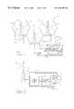
- a cellular communication system 20as in the prior art includes one or more mobile stations or units 21 , one or more base stations 23 and a mobile telephone switching office (MTSO) 25 .
- MTSOmobile telephone switching office
- a typical cellular networkmay comprise hundreds of base stations, thousands of mobile stations and more than one MTSO.
- Each cellwill have allocated to it one or more dedicated control channels and one or more voice channels.
- a typical cellmay have, for example, one control channel, and 21 voice/data, or traffic, channels.
- the control channelis a dedicated channel used for transmitting cell identification and paging information.
- the traffic channelscarry the voice and data information.
- the MTSO 25is the central coordinating element of the overall cellular network 20 . It typically includes a cellular processor 28 , a cellular switch 29 and also provides the interface to the public switched telephone network (PSTN) 30 .
- PSTNpublic switched telephone network
- a duplex radio communication link 32may be effected between two mobile stations 21 or, between a mobile station 21 and a landline telephone user 33 .
- the function of the base station 23is commonly to handle the radio communication with the mobile station 21 . In this capacity, the base station 23 functions chiefly as a relay station for data and voice signals. The base station 23 also supervises the quality of the link 32 and monitors the received signal strength from the mobile station 21 .
- FIG. 2shows, as an example, the functional components of model number RBS 882 manufactured by Ericsson Telecom AB, Sweden for the CMS 8800 cellular mobile telephone system.
- RBS 882manufactured by Ericsson Telecom AB
- FIG. 2shows, as an example, the functional components of model number RBS 882 manufactured by Ericsson Telecom AB, Sweden for the CMS 8800 cellular mobile telephone system.
- RBS 882manufactured by Ericsson Telecom AB
- FIG. 2shows, as an example, the functional components of model number RBS 882 manufactured by Ericsson Telecom AB, Sweden for the CMS 8800 cellular mobile telephone system.
- EN/LZT 101 908 R2Bpublished by Ericsson Telecom AB.
- the base station 23includes a control unit 34 and an antenna tower 35 .
- the control unit 34comprises the base station electronics and is usually positioned within a ruggedized enclosure at, or near, the base of the tower. Within this enclosure are the radio control group 37 , or RCG, an exchange radio interface (ERI) 38 and a primary power supply 41 for converting electric power from the AC grid to power the individual components within the base station 23 , and a backup power supply 42 .
- RCGradio control group 37
- EIexchange radio interface
- the ERI 38provides signals between the MTSO 25 and the base station 23 .
- the ERI 38receives data from the RCG 37 and transfers it to the MTSO 25 on a dedicated MTS0-BS link 45 .
- the ERI 38receives data from the MTSO 25 and sends it the RCG 37 for subsequent transmission to a mobile station 21 .
- the radio control group 37includes the electronic equipment necessary to effect radio communications.
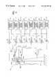
- a functional block diagram of an RCG 37 as in the prior artis shown in FIG. 3 .
- the configuration shownillustrates one control channel transmit/receive module (TRM) 51 , a number of voice channel TRMs 52 , and one signal strength receiver 53 , as is a typical configuration required to serve one cell or sector of a cell.
- Each TRM 51 , 52includes a respective transmitter 54 , receiver 55 and control unit 57 .
- the TRMs 51 , 52are not typically frequency agile and operate instead on only one predetermined channel. Control signals from the ERI 38 are received by the individual control units 57 . Voice and data traffic signals are routed over a separate interface to the ERI 38 .
- Each individual transmitter 54 for control and voiceis connected to a transmit combiner 58 .
- the transmit combinercombines all of the input signals onto a single output coupled through a coaxial cable 62 to the transmit antenna 63 .
- the combiner 58is used because there is often a premium for space on the masts and towers used to support the antennas. In an extreme case, one mast may be required to support over 100 radio channels.
- each of two receive antennas 65is coupled to a respective receive combiner 66 A, 66 B where the signals received are separated according to frequency and passed on to the individual receivers 55 in each of the TRMs 51 , 52 .
- the two receive antennas 65are typically spaced 3 to 5 meters apart on the tower so that they may receive signals with uncorrelated fading patterns to thereby provide space diversity reception.
- There are many conventional techniques for both pre-detection and post-detection diversitywhich are described, for example, in Chapter 10 of the book entitled “ Mobile Communications Engineering ”, by William C. Y. Lee, published by McGraw-Hill, 1992.
- the antenna tower 35One visible feature of a typical base station 23 is the antenna tower 35 .
- the antennas 63 , 65are desirably mounted at some distance above the ground.
- the towers 35are commonly located at the center of a cell 36 thereby providing omni-directional coverage.
- the control channel(s) and the active voice channel(s)are broadcast in all areas of the cell—usually from a single antenna.
- a sectorized antenna systemmay be employed as in the prior art, and shown by the schematic diagram of FIG. 4 B.
- Sectorizationrequires directional antennas 70 having, for example, a 120 degree radiation pattern as illustrated in FIG.
- Each sector 71is itself a cell having its own control channel(s) and traffic channel(s).
- channelmay refer to a specific carrier frequency in an analog system or to a specific carrier/slot combination in a hybrid TDMA/FDMA system, such as IS-54 and GSM.
- FIG. 5Aillustrates a typical antenna system as in the prior art and as discussed above.
- FIG. 5Billustrates two types of prior art antennas that have been heretofore discussed—an omni-directional antenna, such as a dipole 66 , and a directional sector antenna 70 which further includes a reflector 64 , for example. It being understood that transmit and receive antennas are typically of the same type for a given base station.
- Stapletonet al., A Cellular Base Phased Array Antenna System , Proceedings of the 93rd IEEE VTC, pp. 93-96 describe a circular array of monopole radiating elements to provide 360 degree scanning capability.
- Stapleton's antennais designed such that each radiating element has the potential of transmitting on every channel allocated to the cell.
- passive microstrip arraysare also currently available for use with cellular base stations.
- type no. 1309.41.0009 manufactured by Huber+Suhner AG of Herisau, Switzerlandis a seven element linearly polarized flat panel passive antenna with a shaped elevation beam for use in cellular base stations.
- This arraycan replace the typical dipole antenna and is more suitable for locations on the sides of buildings or other flat surfaces.
- application note 20.3, published by Huber+Shunerit is shown that wide area coverage may be obtained via the use of power-splitters whereby portions of the signals are diverted to several individual panels.
- the antenna towermay not permit a sufficient physical separation of receive antennas to achieve uncorrelated fading for receive signals.
- the orientation of the linearly polarized mobile antennamay not always be in alignment with the typically vertically polarized receive antenna at the base station.
- reception at the mobile stationmay also be subject to fading.
- a cellular communications system base stationcapable of providing enhanced communication with a mobile station, particularly in view of fading and/or misorientation of the mobile antenna.
- a base stationcomprising first and second antenna arrays for receiving first and second polarizations, and a polarization diversity receiver connected to the first and second antenna arrays for processing respective first and second receive signals from a mobile station to generate an enhanced quality output receive signal based upon polarization diversity reception.
- the first antenna arrayincludes a first plurality of receive antenna elements for preferably receiving signals having a first polarization and being arranged in a predetermined pattern to define a first receive coverage area.
- the second antenna arraypreferably comprises a second plurality of receive antenna elements for receiving signals having a second polarization different from the first polarization and being arranged in a predetermined pattern to define a second receive coverage area.
- Antenna mounting meansis preferably provided for mounting the first and second antenna arrays so that the first and second receive coverage areas are overlapping.
- the mounting meanspreferably comprises an antenna mast.
- the mounting meansmay comprise another supporting structure such as a wall of a building, for example.
- the polarizationsmay be rotational polarizations.
- the first polarizationmay be right-hand-circular polarization
- the second polarizationmay be left-hand-circular polarization.
- the mobile station antennatypically has a linear polarization, but may be oriented at angles between horizontal and vertical. Accordingly, polarization diversity provides an enhanced receive signal that is less subject to fading.
- the polarization diversity receiverpreferably comprises signal quality determining means for determining signal-to-noise ratios of the first and second receive signals, and weighting means for weighting the first and second receive signals based upon the respective signal-to-noise ratios thereof to thereby generate the enhanced quality output receive signal.
- the polarization diversity receiverpreferably further includes means for separating the first and second receive signals into a plurality of respective individual channels based upon frequency or time slot and for processing each of the individual channels to generate a respective enhanced quality output receive signal based upon polarization diversity reception.
- the first antenna arraypreferably further includes a first plurality of transmit antenna elements arranged in a predetermined pattern for transmitting the second rotational polarization to thereby provide polarization isolation from the first plurality of receive antenna elements.
- the second antenna arraypreferably comprises a second plurality of transmit antenna elements arranged in a predetermined pattern for transmitting the first rotational polarization to thereby provide polarization isolation from the second receive antenna elements.
- a respective one of the receive antenna elements of the first antenna array and a respective one of the transmit antenna elements of the first antenna arraymay be provided on a common patch antenna.
- the common patch antennais capable of receiving signals having one polarization while transmitting signals having another polarization.
- the base stationpreferably further includes alternating polarization transmitter means connected to the first and second pluralities of transmitter antenna elements for alternately transmitting signals at respective alternating first and second rotational polarizations.
- the base stationalso preferably includes transmitter coding means connected to the alternating polarization transmitter means for generating coded and interleaved time division multiple access signals transmitted from the first and second antenna arrays to the mobile station.
- a mobile station for communicating with the cellular base station transmitting the interleaved coded signals at respective alternating first and second rotational polarizationspreferably includes an antenna for receiving signals transmitted from the cellular base station, and receiver means connected to the antenna for deinterleaving and decoding the signals from the cellular base station to thereby achieve polarization diversity gain.
- the interleaved coded signal transmitted from the cellular base stationis preferably a time division multiple access (TDMA) signal, and wherein the receiver means includes means for receiving the TDMA signal.
- TDMAtime division multiple access
- the first antenna arraypreferably comprises an elongate substrate carrying the first plurality of receive antenna elements and the first plurality of transmit antenna elements extending in a vertical direction.
- the second antenna arrayis similar and is mounted adjacent to the first antenna array.
- Each of the first and second antenna arrayspreferably further comprises a plurality of transmit amplifiers on the elongate substrate and connected to respective transmit antenna elements to thereby define an active phased array antenna.
- each of the first and second antenna arrayspreferably further comprises a radio-transparent housing surrounding the elongate substrate.
- a method aspect of the present inventionis for operating a cellular base station for communicating with at least one mobile station.
- the methodpreferably comprises the steps of: receiving a first signal from a mobile station at a first polarization; receiving a second signal from the mobile station at a polarization different from the first polarization; and processing the first and second receive signals to generate an enhanced quality output receive signal based upon polarization diversity reception.
- Another method aspect of the present inventionis for obtaining polarization isolation while also obtaining diversity gain at the mobile station.
- the methodpreferably comprises the steps of: transmitting the second polarization from adjacent the first plurality of receive antenna elements to thereby provide polarization isolation; and transmitting the first polarization from adjacent the second plurality of receive antenna elements to thereby provide polarization isolation.
- the methodalso preferably includes the step of alternately transmitting signals at respective alternating first and second polarizations to provide enhanced received signal quality at a mobile station.
- FIG. 1is a schematic block diagram illustrating the basic components of a cellular communications system as in the prior art
- FIG. 2is a schematic block diagram illustrating the functional components of a cellular communications base station as in the prior art
- FIG. 3is a schematic block diagram illustrating the functional elements of Radio Control Group of a base station as in the prior art
- FIG. 4Ais a schematic plan view illustrating an omni-directional cellular pattern as in the prior art
- FIG. 4Bis a schematic plan view illustrating a sectorized cellular pattern as in the prior art
- FIG. 5Ais a schematic side view illustrating a typical cellular antenna system as in the prior art
- FIG. 5Bis a schematic side view illustrating an omni-directional antenna and a sector antenna as in the prior art
- FIG. 6is a plan view of a base station including a plurality of antenna elements according to the present invention.
- FIG. 7is a cut away view of an antenna array including a plurality of patch antenna elements on an elongate substrate according to FIG. 6;
- FIG. 8is a schematic view of an antenna array according to FIG. 7;
- FIG. 9is a front perspective view of a single patch antenna element on an elongate substrate (fixed) according to FIG. 7;
- FIG. 10is a back perspective view of a single patch antenna element on an elongate substrate according to FIG. 7;
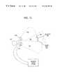
- FIG. 11is a top view of a pair of antenna element arrays defining respective receive coverage areas according to FIG. 6;
- FIG. 12is a top view of a pair of antenna element arrays defining respective transmit coverage areas according to FIG. 6 .
- a base station 200 including a plurality of antenna arraysis described.
- the antenna arraysare arranged in a cylindrical pattern to provide the possibility to transmit or receive in any direction.
- Alternating first 210 a-d and second 212 a-d antenna arraysare for receiving signals having first and second polarizations.
- a polarization diversity receiver 214is connected to each of the first 210 and second 212 antenna arrays for processing respective first and second receive signals received from a mobile station to generate an enhanced quality output receive signal based upon polarization diversity reception.
- the signal from each of the antenna arrays 210 a-d and 212 a-dcan be amplified by a respective amplifier 216 before being applied to a respective polarization diversity receiver 214 .
- each polarization diversity receiverreceives signals from two adjacent antenna arrays.
- a higher degree of polarization diversity receptioncan be achieved by providing signals from more than two adjacent antenna arrays to each polarization diversity receiver.
- each of the first antenna arrays 210 a-dpreferably includes a first plurality of receive antenna elements for receiving signals having a first rotational polarization and being arranged in a predetermined pattern to define a first receive coverage area.
- the antenna elementsmay be circular patch antenna elements (as illustrated in FIGS. 7 and 8) or crossed dipoles as would be readily understood by those skilled in the art.
- these antenna elementsmay serve simultaneously as transmit antenna elements.
- each of the second antenna arrays 212 a -dpreferably comprises a second plurality of receive antenna elements (as illustrated in FIGS. 7 and 8) for receiving a second rotational polarization different from the first rotational polarization and being arranged in a predetermined pattern to define a second receive coverage area.
- these antenna elementsmay serve simultaneously as transmit antenna elements.
- Antenna mounting means, such as the illustrated antenna mast 218is preferably provided for mounting the first and second antenna arrays so that the adjacent receive coverage areas defined by adjacent antenna elements are overlapping.
- the antenna arrayincludes a plurality of printed circuit board antenna elements 224 , such as patch antennas.
- the antenna elements 224such as patch antenna elements, are provided on an elongate substrate 226 such as a printed circuit board, and these patch antennas can be used as transmit and receive elements simultaneously.
- the elongate substratemay also be provided with other components such as input amplifiers 228 , input 230 b or transmit 230 a filters, an output or receive low noise amplifier (“LNA”) 231 , and an output 232 b or receive 232 a filter, as illustrated schematically in FIG. 8 .
- LNAlow noise amplifier
- the elongate substrate 226 with patch antennas 224is preferably enclosed in a radiotransparent tubular housing 234 .
- a mounting bracket 236can be used to connect the antenna array to the base station mast, and the cable 220 can be used to connect the antenna array 223 to respective polarization diversity receivers.
- each antenna element 224is coupled by first coupling circuit 238 including first coupling line 239 to a common receive filter 232 a and low-noise receive amplifier 231 .
- Second coupling circuit 240 including coupling line 241distributes a transmit signal to the transmit power amplifiers 228 .
- the transmit amplifiersmay be either single carrier power amplifiers (SCPA's) for amplifying a Time Division Multiple Access (TDMA) signal, or multi-carrier power amplifier's (MCPA's) for amplifying a composite of several different carrier frequency signals.
- SCPA'ssingle carrier power amplifiers
- MCPA'smulti-carrier power amplifier's
- the receive low noise amplifier 231is preferably always capable of receiving and amplifying signals on multiple frequencies.
- the second coupling circuitmay include switching means for dynamically partitioning the transmit array to provide transmit subarrays operating on different frequencies in the same time slot.
- the transmit amplifiers 228may produce wideband noise outputs at frequencies overlapping the receive frequency band and be of sufficient level to degrade the noise figure of the receive low noise amplifier 231 . Accordingly, transmit 230 a and receive 232 a filters can be used as illustrated.
- the receive filter 232 amay be a bandpass filter tuned to pass the receive frequency band and attenuate transmit frequency signals, while the transmit filters 230 a or input filter 230 b can be notch filters to attenuate transmission in the receive frequency band and pass the transmit frequency band.
- directivity favoring receptionis one way to improve received signal quality.
- Another way to improve the received signal qualityis diversity reception using two or more preferably independent channels, for example, on widely spaced antennas (space diversity), different frequencies (frequency diversity) or at different times (time diversity or interleaved repeat coding).
- space diversitywidely spaced antennas
- frequency diversityfrequency diversity
- time diversitytime diversity or interleaved repeat coding
- Fadingcan be uncorrelated on two antennas spaced only inches apart on a mobile phone, but unfortunately, due to a geometric magnification effect, the spacing required at a base station can be hundreds of times greater. Relatively close spacing is possible at the mobile station because the multiple paths that cause fading tend to arise due to near field clutter in the vicinity of the mobile station, such as due to reflections from objects within a few tens or hundreds of yards.
- the alternate antenna arrays according to the inventionare preferably orthogonally polarized.
- each of the first antenna arrays 210may use orthogonal rotational polarizations such as right-hand-circular-polarization (RHCP) for transmitting and left-hand-circular-polarization (LHCP) for receiving, while each of the second adjacent antenna arrays 212 may use the opposite polarizations for transmitting and receiving.
- RHCPright-hand-circular-polarization
- LHCPleft-hand-circular-polarization
- polarization isolationcan be used in a preferred embodiment to isolate the transmit and receive signals.
- the receive pathspreferably have multi-carrier capability even if the transmitting paths have only single-carrier capability.
- the received signalsare received with both RHCP and LHCP which exhibit uncorrelated fading.
- a diversity gainis obtained which is greater than the directive gain that would have been obtained had all antenna arrays had like receive polarization.
- each antenna arrayis preferably fabricated separately on an elongate substrate 226 such as a long thin module or printed circuit board.
- Printed circuit board antenna elementssuch as patch antennas, may be readily fabricated as part of such a module as would be readily understood by those skilled in the art.
- a circular patch antenna element 224may be fed at two feed points 270 and 272 , and the two feed points connected to a printed, branch-line quadrature coupler 274 to provide two feed points 270 and 272 of opposite circular or rotational polarization.
- a ground connection 276can be used to connect the antenna element 224 to a ground plane 278 shown sandwiched between two layers of the elongate substrate 226 .
- active elementssuch as amplifiers, and passive elements, such as filters, may also be mounted or constructed on the elongate substrate.
- each antenna arraypreferably includes a radio-transparent tubular housing 234 surrounding the elongate substrate 226 .
- a temperature sensor and heatermay be included within the housing.
- collinear antenna arraysmay be mounted on a single antenna mount. Each antenna array thereby provides directivity in the azimuthal plane as well as a narrow beam in the vertical plane, and the arrays may be oriented to cover different azimuthal sectors. This can be done by mounting different collinear arrays around the antenna mast at the same height but pointing to different azimuthal sectors, or by mounting two or more arrays above each other pointing to the same or different azimuthal sectors. In fact, the azimuthal pointing of an array may be set independently of where it is mounted, but it is preferred that the arrays be directed so that there is no interference from the other antenna arrays or the mast.
- the base station 200preferably includes a plurality of antenna arrays 210 a-d and 212 a-d arranged in a circular pattern, as shown in FIG. 6 .
- Signals received from each antenna arrayare transmitted over respective cables 220 to respective amplifiers 216 before being applied to respective polarization diversity receivers 214 .
- cable lossis reduced by integrating masthead preamplifiers into the antenna assembly of FIG. 7 .
- the masthead preamplifiersprovide gains ahead of the respective cables 220 .
- the distribution function of amplifiers 211can alternately be accomplished by means of a passive splitter. Received signals from two adjacent antenna arrays are applied to each polarization diversity receiver, as shown. Accordingly, signals which are received by adjacent antenna arrays can be enhanced by the respective polarization diversity receiver thereby reducing the effect of signal fading.
- a pair of adjacent antenna arrays 210 and 212each define respective receive coverage areas 242 and 244 , as illustrated in FIG. 11 .
- the antenna arraysare mounted on the mast 218 so that the receive coverage areas 242 and 244 define an overlap area 246 .
- a mobile station 248such as a cellular radiotelephone 250 in an automobile, located in the overlap area 246 can transmit signals which are received by both antenna arrays 210 and 212 .
- an overlap areaincludes receive coverage areas from two antenna arrays which both receive signals having orthogonal polarizations from a mobile station in the overlap area
- thisis known as dual polarization diversity.
- higher levels of polarization diversitymay also be achieved in the context of the present invention.
- triple polarization diversitymay be used wherein an overlap area includes coverage areas from three antenna arrays, and a triple polarization diversity receiver is used to combine the signals received by the three antenna arrays.
- higher levels of polarization diversitycan be used for transmission.
- the first antenna array 210preferably receives signals having a first rotational polarization and the second antenna array 212 receives signals having a second rotational polarization. Accordingly, the first antenna array 210 generates a received signal in response to a portion of the signal transmitted by the cellular radiotelephone having the first rotational polarization. In contrast, the second antenna array 212 generates a second received signal in response to a portion of the signal transmitted by the cellular radiotelephone having the second rotational polarization.
- This polarization diversity between the received signals of antenna arrays 210 and 212allows the operation of the polarization diversity receiver 214 .
- both polarizationscan be received on each antenna array, either by constructing receive only arrays or by using duplexing filters in place of transmit filters 230 a .
- a first receive signal having a polarization orthogonal with respect to the transmit signalis fed to the amplifier 231 , as before.
- a second received signalis separated from the transmit path, wherein the second received signal has the same polarization as the transmitted signal.
- a separate amplifier, similar to amplifier 231can be added for this extra receive path, and both polarizations of received signals from one or more antenna arrays can be fed to a multiple diversity receiver 214 .
- the polarization diversity receiver 214preferably includes means, such as channel separators 252 , for separating the first and second receive signals into a plurality of respective individual channels based upon frequency and/or time slot and for processing each of the individual channels to generate a respective enhanced quality output receive signal based upon polarization diversity reception.
- meanssuch as channel separators 252 , for separating the first and second receive signals into a plurality of respective individual channels based upon frequency and/or time slot and for processing each of the individual channels to generate a respective enhanced quality output receive signal based upon polarization diversity reception.
- the polarization diversity receiveralso preferably includes a channel enhancer 254 for processing each pair of associated signals for each channel generated by the channel separators 252 . If only one channel is received by the plurality of antenna arrays, the channel separators 252 can be eliminated, and a single channel enhancer 254 can be used.
- the channel enhancers 254preferably include signal quality determining means for determining signal-to-noise ratios of the first and second receive signals, and weighting means for weighting the first and second receive signals based upon the respective signal-to-noise ratios thereof to thereby generate the enhanced quality output receive signal.
- signal quality determining meansfor determining signal-to-noise ratios of the first and second receive signals
- weighting meansfor weighting the first and second receive signals based upon the respective signal-to-noise ratios thereof to thereby generate the enhanced quality output receive signal.
- Each active antenna array 223includes a plurality of RF power transmit amplifiers 228 each coupled through a transmit filter 230 a to an individual radiating transmit antenna element 224 , as shown in FIG. 8 .
- the antenna elements 224are preferably used to both transmit and receive simultaneously.
- Poweris distributed to each power amplifier 228 via a power dividing network such as coupling circuit 240 .
- the above-mentioned componentsare preferably fabricated using stripline or microstrip techniques on a mounting substrate, such as a glass-epoxy printed circuit board, as would be readily understood by those skilled in the art.
- Dividing means, such as coupling circuit 240can include a plurality of inputs and switching means to select which input signals are distributed to which amplifiers 228 .
- the switching meanscan be activated by pre-programmed control means to determine for each time slot if the full array is used at one transmit frequency or if transmit subarrays are formed for transmitting multiple frequencies simultaneously.
- the coupling circuit 240is a network for distributing RF power from a single input to several outputs and may preferably be a Wilkinson power divider, branch-guide or edge-coupled divider, or other well-known power division device, such as described in Chapter 5 of Bahl, et al., Microwave Solid State Circuit Design , Wiley & Sons, 1988.
- the coupling circuit 240is preferably designed to provide phase coherent outputs to each power transmit amplifier 228 .
- the input powermay be equally divided and in-phase among all of the power amplifier 228 inputs; this is known as uniform illumination and produces a symmetrical radiation pattern. Alternatively, small power imbalances and/or phase offsets can be provided if it is desired to shape the radiation pattern in accordance with basic array theory.
- the switch-selected distribution arrangement of coupling circuit 240can employ an active integrated circuit microwave switch chip.
- each filter 230 ais illustratively coupled to a respective radiating transmit antenna element 224 which may also operate simultaneously as a receive antenna element.
- This antenna elementmay preferably be a linearly-polarized microstrip patch antenna such as described on pages 7-1 to 7-14 of Johnson, et al., Antenna Engineering Handbook— 2 nd Edition , McGraw-Hill, 1984.
- a circularly polarized patch antennasuch as described on pages 7-14 to 7-16 of the aforementioned reference may equivalently be used.
- the antenna arrays 210 a-d and 212 a-dare preferably identical.
- Each antenna arrayis preferably formed from microstrip patch elements 224 , and constructed from a glass-epoxy circuit board using stripline or microstrip techniques, as would be readily understood by those skilled in the art.
- the antenna elements 224are again preferably microstrip patch radiators as described above.
- the patch antenna elements 224are preferably rotationally polarized patch antenna elements. It is preferred that adjacent antenna arrays have opposite rotational polarizations—left hand circular polarization and right hand circular polarization.
- the receive antenna elements 214are coupled to a common output via a combining network such as coupling circuit 238 .
- a combining networksuch as coupling circuit 238 .
- the combining networkcoherently couples the signals received from array elements 214 into a common output.
- the combining networkmay introduce phase offsets or tapered coupling in order to effect beam shaping or to reduce vertical sidelobes, and to reduce unwanted deep nulls to mobiles very close to the mast.
- the output of combining networkis illustratively coupled to a receive filter 232 a and a low-noise amplifier (LNA) 231 .
- LNAlow-noise amplifier
- a similar LNAwas located in the RCG of a conventional base station, and, accordingly, the received signal suffered 2-4 dB of transmission loss through the IFL cabling.
- the amplified receive signal from the LNA 231is also preferably filtered to remove unwanted signal components, such as those generated by the power transmit amplifiers 228 that are not always removed by receive filter 232 a . Therefore the output of LNA 231 is preferably coupled to a bandpass filter such as output filter 232 b .
- the bandpass filtermay be a microstrip edge coupled filter, such as described in Chapter 6 of Bahl, et al., Microwave Solid State Circuit Design , Wiley & Sons, 1988, a high-k ceramic resonator filter, or a SAW filter. Depending on the system bandwidth and transmit/receive duplex spacing, a low-pass, or high-pass filter may also be acceptable as would be readily understood by those skilled in the art.
- Both the transmit signals and the receive signalsare coupled to/from the antenna array 223 via a cable 220 such as an interfacility link (IFL).
- the IFLpreferably comprises a bundle of coaxial cables, and power cables to provide power to the power transmit amplifiers 228 and the LNA 231 .
- the inventionalso includes a method for operating a cellular base station which communicates with at least one mobile station as shown in FIG. 11 .
- the base stationreceives a first signal from the mobile station 250 at a first polarization, and receives a second signal from the mobile station 250 at a polarization different from the first polarization.
- the base stationincludes two antenna arrays 210 and 212 both positioned to receive signals from the overlap region 246 . Accordingly one antenna array receives the signals having the first polarization, and the other antenna array receives the signals having the second polarization.
- the base stationthen processes the first and second receive signals to generate an enhanced quality output receive signal based upon polarization diversity reception.
- Antenna azimuthal radiation patterns similar to conventional 120° sector patternscan be used such that considerable overlaps of adjacent coverage areas of adjacent antenna arrays is deliberately arranged.
- the polarization diversity receiver processingcan alternately be viewed as adaptive array processing, and can be designed either to increase desired signal reception, reduce interference, or to increase signal-to-interference ratios as described in U.S. patent application Ser. No. 08/284,775 entitled “Interference Rejection Combining” to Bottomley. This patent application was filed on Aug. 2, 1994, and is hereby incorporated herein by reference.
- the first and second receive signalsare preferably processed by the diversity receiver 214 .
- the processing steppreferably comprises determining signal-to-noise ratios of the first and second receive signals, and weighing the first and second receive signals based upon the respective signal-to-noise ratios thereof to generate the enhanced quality output receive signal.
- the first and second receive signalscan be separated into a plurality of respective individual channels based upon frequency and each of the individual channels can be processed to generate a respective enhanced quality output receive signal based upon polarization diversity reception.
- the step of receiving the first signalmay include receiving same via a first plurality of receive antenna elements forming antenna array 210 and arranged in a predetermined pattern.
- the step of receiving the second signalmay include receiving same via a second plurality of receive antenna elements forming antenna array 212 and arranged in a predetermined pattern.
- This methodmay also include the step of transmitting the second polarization from adjacent the first receive antenna 210 array, and transmitting the first polarization from adjacent the second receive antenna array 212 , to thereby provide polarization isolation.
- the first antenna array 210can receive signals having the first polarization while transmitting the second polarization
- the second antenna array 212can receive signals having the second rotational polarization while transmitting signals having the first polarization.
- the diversity receiver 214 of FIG. 11 and the transmit signal coder 282 of FIG. 12can be implemented in a single base station.
- the signalscan be alternately transmitted from the base station at respective alternating first and second polarizations to provide enhanced received signal quality at a mobile station.
- the signals transmitted from the base station to the mobile stationcan be coded and interleaved time division multiple access signals.
- the step of receiving the first rotational polarizationcan include receiving right-hand-circular polarization
- the step of receiving the second rotational polarizationcan include receiving left-hand-circular polarization.
- each antenna array 210 and 212can simultaneously cover a mobile station 280 , such as a cellular radiotelephone, in the overlap area 246 .
- a mobile station 280such as a cellular radiotelephone
- the fading of the of the signal received at the mobile stationcan be made substantially uncorrelated in successive segments. Accordingly, polarization diversity gain can be achieved when transmitting from the base station to the mobile station.
- the transmission to the mobile stationcan therefor employ interleaving of coded data over successive segments such that the decoded signal comprises bits taken alternately from successive segments that may be received with relatively high and low quality.
- the average bit quality into the decoderis not all high quality or low quality but adequate to ensure a high probability of error free decoding.
- This techniqueis especially useful for communication with static or walking speed hand held phones that may suffer from slow signal fading.
- the polarization alternationeffectively converts slow fading into faster fading that is more effectively averaged by the coding and interleaving.
- the base stationincludes two adjacent antenna arrays 210 and 212 for transmitting over respective adjacent coverage areas 242 and 244 .
- the antenna arraysare arranged so that the respective coverage areas define an overlap area 246 .
- a mobile station 280such as a hand held cellular radiotelephone, in the overlap area 246 can receive signals transmitted by both antenna arrays 210 and 212 .
- the base stationalso includes a transmit signal coder 282 for processing the signal to be transmitted to the mobile station 280 in the overlap area 246 .
- the transmit signal coderproduces a transmit signal that is interleaved and coded at respective alternating first and second rotational polarizations.
- the portions of the signal having the first rotational polarizationare consistently applied to one of the antenna arrays, and the portions of the signal having the second rotational polarization are applied to the other antenna array.
- a base station controllercan determine for each mobile-base call whether one or the other antenna arrays, or both antenna arrays alternatingly, shall be used for transmitting to the mobile station. This decision can be based on the relative contributions of signals received on the two polarizations as measured in the diversity receivers 214 , or on feedback from the mobile station as to whether transmission from one antenna array or another were preferred. For this purpose, a flag bit can be coded into the transmissions to indicate the polarizations of each transmission.
- the mobile station 280includes an antenna 284 for receiving signals transmitted from the cellular base station, and a receiver 286 connected to the antenna for deinterleaving and decoding the signals from the cellular base station to thereby achieve polarization diversity gain.
- the interleaved coded signal transmitted from the cellular base stationcan be a time division multiple access (TDMA) signal, and the receiver can include means for receiving the TDMA signal.
- TDMAtime division multiple access
- the polarization flag mentioned above, if included on a TDMA burst-by-burst basis,can be decoded to indicate the polarization of each burst received.
- FIG. 12also illustrates a method for communicating between a cellular base station and at least one mobile station 280 including the following steps. Signals are alternately transmitted from the base station at respective alternating first and second polarizations.
- a transmit signal coder 282can be used to separate a single transmit signal into signals having alternating polarizations and applying the signals having alternating polarizations to respective antenna arrays 210 and 212 .
- the mobile station 280receives the alternating first and second polarizations and provides polarization diversity gain.
- the base stationincluding the transmit signal coder 282 and antenna arrays 210 and 212 , preferably generates coded and interleaved time division multiple access signals for transmission at the alternating first and second polarizations.
- the first polarizationis preferably right-hand-circular polarization
- the second polarizationis preferably left-hand-circular polarization.
- a base station for the communications systemcan be defined as a combination of a transmitter and a receiver on one or more satellites under the control of a ground based controller providing connection to a public switched telephone network.
- each of a plurality of transmitter/receiver pairscan provide communications service to different geographic regions or cells.
- the communications systemcan include a plurality of satellites with each satellite having one or more transmitter/receiver pairs.
- a mobile station according to the present inventioncan thus operate as a single mode station providing communication with either a terrestrial communications system or a satellite communications system. Alternately, a mobile station according to the present invention can operate as a dual mode station providing communication with both terrestrial and satellite communications systems.
- the antenna arrays 210 and 212 of FIG. 12can be provided on a satellite in geostationary orbit, each defining a respective coverage area 242 and 244 on the ground. As before, the antenna arrays are arranged so that an overlap coverage area 246 is defined. Accordingly, a mobile station 280 in the overlap area can receive signals transmitted by both antenna arrays.
- the signal coder and the mobile stationoperate as discussed above to provide polarization diversity gain at the mobile station.
- the functionality of the transmit signal codercan be provided at the satellite or at the ground based controller, or the functionality of the transmit signal coder can be shared between the satellite and the ground based controller.
Landscapes
- Engineering & Computer Science (AREA)
- Computer Networks & Wireless Communication (AREA)
- Signal Processing (AREA)
- Radio Transmission System (AREA)
- Mobile Radio Communication Systems (AREA)
- Variable-Direction Aerials And Aerial Arrays (AREA)
Abstract
Description
Claims (23)
Priority Applications (1)
| Application Number | Priority Date | Filing Date | Title |
|---|---|---|---|
| US09/033,179US6201801B1 (en) | 1994-03-24 | 1998-03-02 | Polarization diversity phased array cellular base station and associated methods |
Applications Claiming Priority (3)
| Application Number | Priority Date | Filing Date | Title |
|---|---|---|---|
| US08/217,301US5548813A (en) | 1994-03-24 | 1994-03-24 | Phased array cellular base station and associated methods for enhanced power efficiency |
| US08/439,116US5724666A (en) | 1994-03-24 | 1995-05-11 | Polarization diversity phased array cellular base station and associated methods |
| US09/033,179US6201801B1 (en) | 1994-03-24 | 1998-03-02 | Polarization diversity phased array cellular base station and associated methods |
Related Parent Applications (1)
| Application Number | Title | Priority Date | Filing Date |
|---|---|---|---|
| US08/439,116Continuation-In-PartUS5724666A (en) | 1994-03-24 | 1995-05-11 | Polarization diversity phased array cellular base station and associated methods |
Publications (1)
| Publication Number | Publication Date |
|---|---|
| US6201801B1true US6201801B1 (en) | 2001-03-13 |
Family
ID=26911817
Family Applications (1)
| Application Number | Title | Priority Date | Filing Date |
|---|---|---|---|
| US09/033,179Expired - LifetimeUS6201801B1 (en) | 1994-03-24 | 1998-03-02 | Polarization diversity phased array cellular base station and associated methods |
Country Status (1)
| Country | Link |
|---|---|
| US (1) | US6201801B1 (en) |
Cited By (50)
| Publication number | Priority date | Publication date | Assignee | Title |
|---|---|---|---|---|
| US20020103013A1 (en)* | 2001-01-31 | 2002-08-01 | Watson Stephen J. | Signal detection using a phased array antenna |
| US20020140521A1 (en)* | 2001-03-29 | 2002-10-03 | Alcatel | Microwave filter and a telecommunication antenna including |
| US20030004519A1 (en)* | 2001-06-29 | 2003-01-02 | Ian Torode | Tool and system for aligning and applying fastener to implanted anchor |
| US20030003959A1 (en)* | 2001-06-28 | 2003-01-02 | Tsui Ernest T. | Antenna for wireless systems |
| US20030073427A1 (en)* | 2001-09-28 | 2003-04-17 | Bertram Geck | System and method for inhibiting features for wireless terminals |
| US20030092379A1 (en)* | 2001-11-15 | 2003-05-15 | Brothers Louis R. | Method and apparatus for received uplink-signal based adaptive downlink diversity within a communication system |
| FR2833784A1 (en)* | 2001-12-18 | 2003-06-20 | Thales Sa | ANTI-JAMMING METHOD FOR A SPREAD SPECTRUM RADIOELECTRIC SIGNAL RECEIVER |
| US20030190918A1 (en)* | 2002-04-03 | 2003-10-09 | Ophir Frieder | Process to allocate channels in a sectorized and tiered cellular network |
| US20030224729A1 (en)* | 2002-05-28 | 2003-12-04 | Arnold Kenneth David | Interference resistant wireless sensor and control system |
| US20040106411A1 (en)* | 2002-04-03 | 2004-06-03 | Nguyen Vincent Anhdzung | Process to allocate channels in a sectorized cellular network |
| US20040204109A1 (en)* | 2002-09-30 | 2004-10-14 | Andrew Corporation | Active array antenna and system for beamforming |
| US20040212587A1 (en)* | 2003-04-25 | 2004-10-28 | Microsoft Corporation | Computer input device with angular displacement detection capabilities |
| US20040266501A1 (en)* | 2003-06-27 | 2004-12-30 | Peek Gregory A. | Apparatus and method to provide antenna diversity |
| US20070041336A1 (en)* | 2005-07-28 | 2007-02-22 | Ming Wan | Distributed tempero-spatial query service |
| US20070111749A1 (en)* | 2005-11-15 | 2007-05-17 | Clearone Communications, Inc. | Wireless communications device with reflective interference immunity |
| US20070109194A1 (en)* | 2005-11-15 | 2007-05-17 | Clearone Communications, Inc. | Planar anti-reflective interference antennas with extra-planar element extensions |
| US20070109193A1 (en)* | 2005-11-15 | 2007-05-17 | Clearone Communications, Inc. | Anti-reflective interference antennas with radially-oriented elements |
| US20070142057A1 (en)* | 2005-12-15 | 2007-06-21 | Fujitsu Limited | Dynamic cell reconfiguring method and cellular network system to which the method is applied |
| US7277728B1 (en)* | 2000-05-05 | 2007-10-02 | Nokia Corporation | Base station of a communication network, preferably of a mobile telecommunication network |
| US20070274346A1 (en)* | 2006-05-23 | 2007-11-29 | Lord Bruce J | Methods and apparatus for network joining using a multiple message per tdma control slot methodology |
| US20080117883A1 (en)* | 2006-11-17 | 2008-05-22 | Xg Technology, Inc. | Time coordinated base station and antenna array for integer cycle and impulse modulation systems |
| US20080238688A1 (en)* | 2007-03-30 | 2008-10-02 | Broadcom Corporation | Dynamic rf front end |
| US20090066595A1 (en)* | 2006-08-18 | 2009-03-12 | Quintel Technology Limited | Diversity Antenna System with Electrical Tilt |
| US20090088213A1 (en)* | 2007-09-28 | 2009-04-02 | Rofougaran Ahmadreza Reza | Method and system for sharing multiple antennas between tx and rx in a repeat field of polarization isolation |
| US20090088069A1 (en)* | 2007-09-28 | 2009-04-02 | Rofougaran Ahmadreza Reza | Method and system for repeater with gain control and isolation via polarization |
| US20100046487A1 (en)* | 2008-08-21 | 2010-02-25 | Qualcomm Incorporated | Multichannel architecture for high throughput modems |
| US20100130264A1 (en)* | 2008-11-21 | 2010-05-27 | Yong Su-Khiong | Method and system for communication of different modulation formats from a wireless station in a wireless system |
| US20100227647A1 (en)* | 2009-03-03 | 2010-09-09 | Hitachi Cable, Ltd. | Mobile communication base station antenna |
| US20110080970A1 (en)* | 2009-07-27 | 2011-04-07 | Andrea De Pasquale | Data Transmission in a Wide Area Mobile Network |
| WO2012003061A1 (en)* | 2010-06-29 | 2012-01-05 | Rambus Inc. | Methods and systems for near-field mimo communication |
| US20120093100A1 (en)* | 2010-09-28 | 2012-04-19 | Youming Qin | Systems and Methods for Wireless Communication Using Polarization Diversity |
| US8797837B2 (en) | 2008-12-03 | 2014-08-05 | Samsung Electronics Co., Ltd. | System and method for in-phase/quadrature multiplexing |
| WO2014130877A1 (en)* | 2013-02-22 | 2014-08-28 | Quintel Technology Limited | Multi-array antenna |
| US8867679B2 (en) | 2010-09-28 | 2014-10-21 | Aviat U.S., Inc. | Systems and methods for cancelling cross polarization interference in wireless communication using polarization diversity |
| US9680234B2 (en) | 2013-08-28 | 2017-06-13 | Harris Corporation | Dual polarization ground-based phased array antenna system for aircraft communications and associated methods |
| US10468782B1 (en)* | 2019-04-16 | 2019-11-05 | The United States Of America As Represented By The Secretary Of The Navy | Method for determining the instantaneous polarization of propagating electromagnetic waves |
| CN113659339A (en)* | 2021-08-23 | 2021-11-16 | 深圳市道通智能汽车有限公司 | Vehicle-mounted millimeter wave radar, transmitting antenna and receiving antenna system thereof, and antenna system |
| US20220069853A1 (en)* | 2020-08-28 | 2022-03-03 | Isco International, Llc | Method and system for addressing interference by configuring or adapting antenna structures |
| RU2805479C2 (en)* | 2015-04-10 | 2023-10-17 | Виасат, Инк. | Satellite for end-to-end formation of direct beam |
| US11843448B2 (en) | 2015-04-10 | 2023-12-12 | Viasat, Inc. | Satellite for end to end beamforming |
| US11949489B1 (en) | 2022-10-17 | 2024-04-02 | Isco International, Llc | Method and system for improving multiple-input-multiple-output (MIMO) beam isolation via alternating polarization |
| US11949168B2 (en) | 2022-03-31 | 2024-04-02 | Isco International, Llc | Method and system for driving polarization shifting to mitigate interference |
| US11956058B1 (en) | 2022-10-17 | 2024-04-09 | Isco International, Llc | Method and system for mobile device signal to interference plus noise ratio (SINR) improvement via polarization adjusting/optimization |
| US11985692B2 (en) | 2022-10-17 | 2024-05-14 | Isco International, Llc | Method and system for antenna integrated radio (AIR) downlink and uplink beam polarization adaptation |
| US11990976B2 (en) | 2022-10-17 | 2024-05-21 | Isco International, Llc | Method and system for polarization adaptation to reduce propagation loss for a multiple-input-multiple-output (MIMO) antenna |
| US12219522B1 (en) | 2023-12-29 | 2025-02-04 | Isco International, Llc | Methods and systems for estimating the shape of an object generating passive intermodulation (PIM) interference |
| US12301315B1 (en) | 2023-12-29 | 2025-05-13 | Isco International, Llc | Methods and systems for detecting, measuring, and/or locating passive intermodulation sources via downlink (DL) signal injection |
| US12301298B1 (en) | 2023-12-29 | 2025-05-13 | Isco International, Llc | Methods and systems for locating interference sources via angle of arrival (AoA) |
| US12348285B1 (en) | 2023-12-29 | 2025-07-01 | Isco International, Llc | Methods and systems for detecting, measuring, and/or locating passive intermodulation (PIM) sources via beamforming |
| US12438268B2 (en) | 2022-03-31 | 2025-10-07 | Isco International, Llc | Method and system for detecting interference and controlling polarization shifting to mitigate the interference |
Citations (52)
| Publication number | Priority date | Publication date | Assignee | Title |
|---|---|---|---|---|
| US2992427A (en) | 1960-02-19 | 1961-07-11 | Gen Dynamics Corp | Polarization modulation data transmission system |
| US3835392A (en) | 1970-12-03 | 1974-09-10 | Siemens Ag | System for two or more combined communication channels regulated in accordance with linear relationships |
| US4072956A (en) | 1976-05-17 | 1978-02-07 | The United States Of America As Represented By The Secretary Of The Navy | Multifrequency array using common phasors |
| US4101836A (en) | 1977-05-02 | 1978-07-18 | Motorola, Inc. | Sectored antenna receiving system |
| US4128740A (en) | 1977-02-14 | 1978-12-05 | Motorola, Inc. | Antenna array for a cellular RF communications system |
| US4204093A (en) | 1978-05-19 | 1980-05-20 | Bell Telephone Laboratories, Incorporated | Variable frame rate technique for use in a time-division multiple access (TDMA) communication system |
| EP0160993A2 (en) | 1984-05-10 | 1985-11-13 | Alcatel SEL Aktiengesellschaft | Radio-system |
| EP0201254A2 (en) | 1985-05-03 | 1986-11-12 | AT&T Corp. | Terrestrial communications system base station |
| US4630316A (en) | 1982-12-14 | 1986-12-16 | Vaughan Thomas J | Transition between rectangular and relatively large circular waveguide for a UHF broadcast antenna |
| US4724441A (en) | 1986-05-23 | 1988-02-09 | Ball Corporation | Transmit/receive module for phased array antenna system |
| US4814773A (en) | 1983-05-11 | 1989-03-21 | Hughes Aircraft Company | Fiber optic feed network for radar |
| US4823136A (en) | 1987-02-11 | 1989-04-18 | Westinghouse Electric Corp. | Transmit-receive means for phased-array active antenna system using rf redundancy |
| US4846990A (en) | 1987-01-24 | 1989-07-11 | Henkel Kommanditgesellschaft Auf Aktien | Fabric-softening detergent |
| GB2221820A (en) | 1988-06-15 | 1990-02-14 | Matsushita Electric Works Ltd | Polarization diversity radio communication system |
| WO1990003071A1 (en) | 1988-09-05 | 1990-03-22 | Aahl Karl Axel | Method and system in a wide area radio communication network |
| WO1992002996A1 (en) | 1990-08-07 | 1992-02-20 | Inventahl Ab | Modular radio communication system |
| US5166693A (en) | 1989-12-11 | 1992-11-24 | Kabushiki Kaisha Toyota Chuo Kenkyusho | Mobile antenna system |
| US5187807A (en) | 1989-06-12 | 1993-02-16 | Matra Communication | Base station for a radiotelephone communication system with switchig members for connecting link lines to transmitter members |
| US5191598A (en) | 1990-02-16 | 1993-03-02 | Telefonaktiebolaget L M Ericsson | System for reducing the affects of signal fading on received signals |
| US5200759A (en) | 1991-06-03 | 1993-04-06 | Mcginnis Henry J | Telecommunications tower equipment housing |
| WO1993012590A1 (en) | 1991-12-12 | 1993-06-24 | Arraycomm, Incorporated | Spatial division multiple access wireless communication systems |
| US5241690A (en) | 1990-06-21 | 1993-08-31 | Telefonaktiebolaget L M Ericsson | Method for regulating power in a digital mobile telephony system |
| US5276452A (en) | 1992-06-24 | 1994-01-04 | Raytheon Company | Scan compensation for array antenna on a curved surface |
| US5280631A (en) | 1988-06-15 | 1994-01-18 | Matsushita Electric Works, Ltd. | Polarization diversity system suitable for radio communication in indoor space |
| US5299198A (en) | 1990-12-06 | 1994-03-29 | Hughes Aircraft Company | Method and apparatus for exploitation of voice inactivity to increase the capacity of a time division multiple access radio communications system |
| US5301188A (en) | 1990-02-27 | 1994-04-05 | Motorola, Inc. | Shared-carrier frequency hopping |
| EP0593822A1 (en) | 1992-10-19 | 1994-04-27 | Nortel Networks Corporation | Base station antenna arrangement |
| WO1994011958A1 (en) | 1992-11-09 | 1994-05-26 | Telefonaktiebolaget Lm Ericsson | A radio module included in a primary radio station, and a radio structure containing such modules |
| US5321850A (en) | 1991-10-09 | 1994-06-14 | Telefonaktiebolaget L M Ericsson | Diversity radio receiver automatic frequency control |
| US5339086A (en) | 1993-02-22 | 1994-08-16 | General Electric Co. | Phased array antenna with distributed beam steering |
| US5369681A (en) | 1992-05-12 | 1994-11-29 | Telefonaktiebolaget L M Ericsson | Cellular communications system utilizing paging areas |
| US5388100A (en) | 1993-02-26 | 1995-02-07 | Fujitsu Limited | Receiving circuit for digital data transmitted by wireless communication |
| GB2281011A (en) | 1993-08-12 | 1995-02-15 | Northern Telecom Ltd | Base station antenna arrangement |
| US5432780A (en) | 1988-09-12 | 1995-07-11 | Motorola, Inc. | High capacity sectorized cellular communication system |
| US5485631A (en) | 1991-02-22 | 1996-01-16 | Motorola, Inc. | Manifold antenna structure for reducing reuse factors |
| US5499395A (en) | 1993-03-11 | 1996-03-12 | Hitachi, Ltd. | Cellular mobile communication system having apparatus for changing boundaries of cells according to traffic condition |
| US5511110A (en) | 1994-11-09 | 1996-04-23 | U S West, Inc. | Cellular phone page system using sequential transmissions of pages over a time-partitioned forward control channel |
| US5513183A (en) | 1990-12-06 | 1996-04-30 | Hughes Aircraft Company | Method for exploitation of voice inactivity to increase the capacity of a time division multiple access radio communications system |
| US5528581A (en) | 1992-12-01 | 1996-06-18 | U.S. Philips Corporation | Diversity transmission system for sub-band diversity reception |
| US5548813A (en) | 1994-03-24 | 1996-08-20 | Ericsson Inc. | Phased array cellular base station and associated methods for enhanced power efficiency |
| US5563610A (en) | 1995-06-08 | 1996-10-08 | Metawave Communications Corporation | Narrow beam antenna systems with angular diversity |
| US5565873A (en) | 1993-08-12 | 1996-10-15 | Northern Telecom Limited | Base station antenna arrangement |
| US5579306A (en) | 1994-09-01 | 1996-11-26 | Ericsson Inc. | Time and frequency slot allocation system and method |
| US5608722A (en) | 1995-04-03 | 1997-03-04 | Qualcomm Incorporated | Multi-user communication system architecture with distributed receivers |
| US5621752A (en) | 1994-06-23 | 1997-04-15 | Qualcomm Incorporated | Adaptive sectorization in a spread spectrum communication system |
| US5649308A (en)* | 1993-04-12 | 1997-07-15 | Trw Inc. | Multiformat auto-handoff communications handset |
| US5724666A (en) | 1994-03-24 | 1998-03-03 | Ericsson Inc. | Polarization diversity phased array cellular base station and associated methods |
| US5841816A (en)* | 1992-10-22 | 1998-11-24 | Ericsson Inc. | Diversity Pi/4-DQPSK demodulation |
| US5859842A (en)* | 1994-11-03 | 1999-01-12 | Omnipoint Corporation | Antenna diversity techniques |
| US5933421A (en)* | 1997-02-06 | 1999-08-03 | At&T Wireless Services Inc. | Method for frequency division duplex communications |
| US6002672A (en)* | 1996-10-25 | 1999-12-14 | Nortel Networks Corporation | Diversity antenna selection |
| US6023606A (en)* | 1995-06-07 | 2000-02-08 | Globalstar L.P. | Method for accounting for user terminal connection to a satellite communications system |
- 1998
- 1998-03-02USUS09/033,179patent/US6201801B1/ennot_activeExpired - Lifetime
Patent Citations (53)
| Publication number | Priority date | Publication date | Assignee | Title |
|---|---|---|---|---|
| US2992427A (en) | 1960-02-19 | 1961-07-11 | Gen Dynamics Corp | Polarization modulation data transmission system |
| US3835392A (en) | 1970-12-03 | 1974-09-10 | Siemens Ag | System for two or more combined communication channels regulated in accordance with linear relationships |
| US4072956A (en) | 1976-05-17 | 1978-02-07 | The United States Of America As Represented By The Secretary Of The Navy | Multifrequency array using common phasors |
| US4128740A (en) | 1977-02-14 | 1978-12-05 | Motorola, Inc. | Antenna array for a cellular RF communications system |
| US4101836A (en) | 1977-05-02 | 1978-07-18 | Motorola, Inc. | Sectored antenna receiving system |
| US4204093A (en) | 1978-05-19 | 1980-05-20 | Bell Telephone Laboratories, Incorporated | Variable frame rate technique for use in a time-division multiple access (TDMA) communication system |
| US4630316A (en) | 1982-12-14 | 1986-12-16 | Vaughan Thomas J | Transition between rectangular and relatively large circular waveguide for a UHF broadcast antenna |
| US4814773A (en) | 1983-05-11 | 1989-03-21 | Hughes Aircraft Company | Fiber optic feed network for radar |
| EP0160993A2 (en) | 1984-05-10 | 1985-11-13 | Alcatel SEL Aktiengesellschaft | Radio-system |
| EP0201254A2 (en) | 1985-05-03 | 1986-11-12 | AT&T Corp. | Terrestrial communications system base station |
| US4724441A (en) | 1986-05-23 | 1988-02-09 | Ball Corporation | Transmit/receive module for phased array antenna system |
| US4846990A (en) | 1987-01-24 | 1989-07-11 | Henkel Kommanditgesellschaft Auf Aktien | Fabric-softening detergent |
| US4823136A (en) | 1987-02-11 | 1989-04-18 | Westinghouse Electric Corp. | Transmit-receive means for phased-array active antenna system using rf redundancy |
| GB2221820A (en) | 1988-06-15 | 1990-02-14 | Matsushita Electric Works Ltd | Polarization diversity radio communication system |
| US5280631A (en) | 1988-06-15 | 1994-01-18 | Matsushita Electric Works, Ltd. | Polarization diversity system suitable for radio communication in indoor space |
| WO1990003071A1 (en) | 1988-09-05 | 1990-03-22 | Aahl Karl Axel | Method and system in a wide area radio communication network |
| US5432780A (en) | 1988-09-12 | 1995-07-11 | Motorola, Inc. | High capacity sectorized cellular communication system |
| US5187807A (en) | 1989-06-12 | 1993-02-16 | Matra Communication | Base station for a radiotelephone communication system with switchig members for connecting link lines to transmitter members |
| US5166693A (en) | 1989-12-11 | 1992-11-24 | Kabushiki Kaisha Toyota Chuo Kenkyusho | Mobile antenna system |
| US5191598A (en) | 1990-02-16 | 1993-03-02 | Telefonaktiebolaget L M Ericsson | System for reducing the affects of signal fading on received signals |
| US5301188A (en) | 1990-02-27 | 1994-04-05 | Motorola, Inc. | Shared-carrier frequency hopping |
| US5241690A (en) | 1990-06-21 | 1993-08-31 | Telefonaktiebolaget L M Ericsson | Method for regulating power in a digital mobile telephony system |
| WO1992002996A1 (en) | 1990-08-07 | 1992-02-20 | Inventahl Ab | Modular radio communication system |
| US5299198A (en) | 1990-12-06 | 1994-03-29 | Hughes Aircraft Company | Method and apparatus for exploitation of voice inactivity to increase the capacity of a time division multiple access radio communications system |
| US5513183A (en) | 1990-12-06 | 1996-04-30 | Hughes Aircraft Company | Method for exploitation of voice inactivity to increase the capacity of a time division multiple access radio communications system |
| US5485631A (en) | 1991-02-22 | 1996-01-16 | Motorola, Inc. | Manifold antenna structure for reducing reuse factors |
| US5200759A (en) | 1991-06-03 | 1993-04-06 | Mcginnis Henry J | Telecommunications tower equipment housing |
| US5321850A (en) | 1991-10-09 | 1994-06-14 | Telefonaktiebolaget L M Ericsson | Diversity radio receiver automatic frequency control |
| WO1993012590A1 (en) | 1991-12-12 | 1993-06-24 | Arraycomm, Incorporated | Spatial division multiple access wireless communication systems |
| US5515378A (en) | 1991-12-12 | 1996-05-07 | Arraycomm, Inc. | Spatial division multiple access wireless communication systems |
| US5369681A (en) | 1992-05-12 | 1994-11-29 | Telefonaktiebolaget L M Ericsson | Cellular communications system utilizing paging areas |
| US5276452A (en) | 1992-06-24 | 1994-01-04 | Raytheon Company | Scan compensation for array antenna on a curved surface |
| EP0593822A1 (en) | 1992-10-19 | 1994-04-27 | Nortel Networks Corporation | Base station antenna arrangement |
| US5841816A (en)* | 1992-10-22 | 1998-11-24 | Ericsson Inc. | Diversity Pi/4-DQPSK demodulation |
| WO1994011958A1 (en) | 1992-11-09 | 1994-05-26 | Telefonaktiebolaget Lm Ericsson | A radio module included in a primary radio station, and a radio structure containing such modules |
| US5528581A (en) | 1992-12-01 | 1996-06-18 | U.S. Philips Corporation | Diversity transmission system for sub-band diversity reception |
| US5339086A (en) | 1993-02-22 | 1994-08-16 | General Electric Co. | Phased array antenna with distributed beam steering |
| US5388100A (en) | 1993-02-26 | 1995-02-07 | Fujitsu Limited | Receiving circuit for digital data transmitted by wireless communication |
| US5499395A (en) | 1993-03-11 | 1996-03-12 | Hitachi, Ltd. | Cellular mobile communication system having apparatus for changing boundaries of cells according to traffic condition |
| US5649308A (en)* | 1993-04-12 | 1997-07-15 | Trw Inc. | Multiformat auto-handoff communications handset |
| US5565873A (en) | 1993-08-12 | 1996-10-15 | Northern Telecom Limited | Base station antenna arrangement |
| GB2281011A (en) | 1993-08-12 | 1995-02-15 | Northern Telecom Ltd | Base station antenna arrangement |
| US5724666A (en) | 1994-03-24 | 1998-03-03 | Ericsson Inc. | Polarization diversity phased array cellular base station and associated methods |
| US5548813A (en) | 1994-03-24 | 1996-08-20 | Ericsson Inc. | Phased array cellular base station and associated methods for enhanced power efficiency |
| US5621752A (en) | 1994-06-23 | 1997-04-15 | Qualcomm Incorporated | Adaptive sectorization in a spread spectrum communication system |
| US5579306A (en) | 1994-09-01 | 1996-11-26 | Ericsson Inc. | Time and frequency slot allocation system and method |
| US5859842A (en)* | 1994-11-03 | 1999-01-12 | Omnipoint Corporation | Antenna diversity techniques |
| US5511110A (en) | 1994-11-09 | 1996-04-23 | U S West, Inc. | Cellular phone page system using sequential transmissions of pages over a time-partitioned forward control channel |
| US5608722A (en) | 1995-04-03 | 1997-03-04 | Qualcomm Incorporated | Multi-user communication system architecture with distributed receivers |
| US6023606A (en)* | 1995-06-07 | 2000-02-08 | Globalstar L.P. | Method for accounting for user terminal connection to a satellite communications system |
| US5563610A (en) | 1995-06-08 | 1996-10-08 | Metawave Communications Corporation | Narrow beam antenna systems with angular diversity |
| US6002672A (en)* | 1996-10-25 | 1999-12-14 | Nortel Networks Corporation | Diversity antenna selection |
| US5933421A (en)* | 1997-02-06 | 1999-08-03 | At&T Wireless Services Inc. | Method for frequency division duplex communications |
Non-Patent Citations (15)
| Title |
|---|
| Carlo Caini, et al., A Spectrum- and Power-Efficient EHF Mobile Satellite System to be Integrated with Terrestrial Cellular Systems, IEEE Journal on Selected Areas in Communications, vol. 10, No. 8, Oct. 1992, pp. 1315-1325. |
| Donald C. Cox, Antenna Diversity Performance in Mitigating the Effects of Portable Radiotelephone Orientation and Multipath Propagation, IEEE Transactions on Communications, vol. Com-31, No. 5, May 1983, pp. 620-628. |
| Donald C. Cox, et al., Cross-Polarization Coupling Measured for 800 MHz Radio Transmission In and Around Houses and Large Buildings, IEEE Transactions on Antennas and Propagation, vol. AP-34, No. 1, Jan. 1986, pp. 83-87. |
| International Search Report, PCT/US95/02464, Jun. 19,1995. |
| International Search Report, PCT/US96/06366, Sep. 20, 1996. |
| Jean-Francois Lemieux, et al., Experimental Evaluation of Space/Frequency/Polarization Diversity in the Indoor Wireless Channel, IEEE Transactions on Vehicular Technology, vol. 40, No. 3, Aug. 1991, pp. 569-574. |
| John L. Everett, Potential developments in hand-held satellite communication terminals, European Satellite Communications 89: Blenheim Online Publications, Pinner, Middx, UK. 1989, pp. 25-34. |
| P. S. Henry, et al., A New Approach to High-Capacity Digital Mobile Radio, American Telephone and Telegraph Company, The Bell System Technical Journal, vol. 60, No. 8, Oct. 1981, pp. 1891-1904. |
| Polarisation Diversity In Portable Communications Environment, Electronics Letter, vol. 22, No. 11, May 22, 1986, pp. 609-610. |
| R.G. Vaughan et al., Antenna Diversity For Mobile Communications, Nordic Seminar On Digital Land Mobile Radiocommunication, Feb. 5-7, 1985, Espoo, Finland, pp. 87-96. |
| S.P. Stapleton, et al., A Cellular Base Station Phased Array Antenna System, IEEE, 1993, pp. 93-96. |
| Swales et al., A Spectrum Efficient Cellular Base-Station Antenna Architecture, Personal and Mobile Radio Communications Conference, Dec. 9-11, 1991, Coventry, UK, pp. 272-279. |
| Tomasi, Wayne, Electronic Communications Systems: Fundamentals Through Advanced, 2d, pp. 694-697, 356-359 (Prentice-Hall, 1994). |
| William C.Y. Lee, Mobile Communications Engineering, Chapter 10: Combining Technology, McGraw-Hill Book Company, 1992, pp. 291-336. |
| William C.-Y. Lee, Polarization Diversity System for Mobile Radio, IEEE Transactions On Communications, vol. Comm. 20, No. 5, Oct. 1972, pp. 912-923. |
Cited By (104)
| Publication number | Priority date | Publication date | Assignee | Title |
|---|---|---|---|---|
| US7277728B1 (en)* | 2000-05-05 | 2007-10-02 | Nokia Corporation | Base station of a communication network, preferably of a mobile telecommunication network |
| US20020103013A1 (en)* | 2001-01-31 | 2002-08-01 | Watson Stephen J. | Signal detection using a phased array antenna |
| US6737937B2 (en) | 2001-03-29 | 2004-05-18 | Alcatel | Microwave filter and a telecommunication antenna including it |
| US20020140521A1 (en)* | 2001-03-29 | 2002-10-03 | Alcatel | Microwave filter and a telecommunication antenna including |
| FR2823019A1 (en)* | 2001-03-29 | 2002-10-04 | Cit Alcatel | TELECOMMUNICATIONS ANTENNA AND FILTERING DEVICE |
| EP1249889A1 (en)* | 2001-03-29 | 2002-10-16 | Alcatel | Microwave filter with a dielectric resonator |
| US20030003959A1 (en)* | 2001-06-28 | 2003-01-02 | Tsui Ernest T. | Antenna for wireless systems |
| US7158813B2 (en)* | 2001-06-28 | 2007-01-02 | Intel Corporation | Antenna for wireless systems |
| US20030004519A1 (en)* | 2001-06-29 | 2003-01-02 | Ian Torode | Tool and system for aligning and applying fastener to implanted anchor |
| US20030073427A1 (en)* | 2001-09-28 | 2003-04-17 | Bertram Geck | System and method for inhibiting features for wireless terminals |
| US7567803B2 (en)* | 2001-09-28 | 2009-07-28 | Siemens Aktiengesellschaft | System and method for inhibiting features for wireless terminals |
| US7095987B2 (en) | 2001-11-15 | 2006-08-22 | Texas Instruments Incorporated | Method and apparatus for received uplinked-signal based adaptive downlink diversity within a communication system |
| US20030092379A1 (en)* | 2001-11-15 | 2003-05-15 | Brothers Louis R. | Method and apparatus for received uplink-signal based adaptive downlink diversity within a communication system |
| WO2003055102A3 (en)* | 2001-12-18 | 2004-09-30 | Thales Sa | Anti-jamming method for spread-spectrum radio signal receivers |
| US7386034B2 (en) | 2001-12-18 | 2008-06-10 | Thales | Anti-jamming method for spread-spectrum radio signal receivers |
| FR2833784A1 (en)* | 2001-12-18 | 2003-06-20 | Thales Sa | ANTI-JAMMING METHOD FOR A SPREAD SPECTRUM RADIOELECTRIC SIGNAL RECEIVER |
| US20050078739A1 (en)* | 2001-12-18 | 2005-04-14 | Damien Korpet | Anti- jamming method for spread-spectrum radio signal receivers |
| US8195172B2 (en) | 2002-04-03 | 2012-06-05 | Illinois Institute Of Technology | Process to allocate channels in a sectorized and tiered cellular network |
| US20040106411A1 (en)* | 2002-04-03 | 2004-06-03 | Nguyen Vincent Anhdzung | Process to allocate channels in a sectorized cellular network |
| US8165591B2 (en) | 2002-04-03 | 2012-04-24 | Illinois Institute Of Technology | Process to allocate channels in a sectorized cellular network |
| US20030190918A1 (en)* | 2002-04-03 | 2003-10-09 | Ophir Frieder | Process to allocate channels in a sectorized and tiered cellular network |
| US20030224729A1 (en)* | 2002-05-28 | 2003-12-04 | Arnold Kenneth David | Interference resistant wireless sensor and control system |
| US6990317B2 (en) | 2002-05-28 | 2006-01-24 | Wireless Innovation | Interference resistant wireless sensor and control system |
| GB2422961A (en)* | 2002-09-30 | 2006-08-09 | Andrew Corp | Base-station with optical base-band mast link and linearization of active beamforming array antenna amplifiers |
| GB2422961B (en)* | 2002-09-30 | 2006-10-11 | Andrew Corp | An antenna base station |
| US7280848B2 (en) | 2002-09-30 | 2007-10-09 | Andrew Corporation | Active array antenna and system for beamforming |
| US20040204109A1 (en)* | 2002-09-30 | 2004-10-14 | Andrew Corporation | Active array antenna and system for beamforming |
| US20040212587A1 (en)* | 2003-04-25 | 2004-10-28 | Microsoft Corporation | Computer input device with angular displacement detection capabilities |
| US7010335B2 (en)* | 2003-06-27 | 2006-03-07 | Intel Corporation | Apparatus and method to provide antenna diversity |
| US20040266501A1 (en)* | 2003-06-27 | 2004-12-30 | Peek Gregory A. | Apparatus and method to provide antenna diversity |
| US20070041336A1 (en)* | 2005-07-28 | 2007-02-22 | Ming Wan | Distributed tempero-spatial query service |
| US7616590B2 (en)* | 2005-07-28 | 2009-11-10 | The Boeing Company | Distributed tempero-spatial query service |
| US20070109193A1 (en)* | 2005-11-15 | 2007-05-17 | Clearone Communications, Inc. | Anti-reflective interference antennas with radially-oriented elements |
| US7333068B2 (en) | 2005-11-15 | 2008-02-19 | Clearone Communications, Inc. | Planar anti-reflective interference antennas with extra-planar element extensions |
| US20070111749A1 (en)* | 2005-11-15 | 2007-05-17 | Clearone Communications, Inc. | Wireless communications device with reflective interference immunity |
| US20070109194A1 (en)* | 2005-11-15 | 2007-05-17 | Clearone Communications, Inc. | Planar anti-reflective interference antennas with extra-planar element extensions |
| US7446714B2 (en) | 2005-11-15 | 2008-11-04 | Clearone Communications, Inc. | Anti-reflective interference antennas with radially-oriented elements |
| US7480502B2 (en) | 2005-11-15 | 2009-01-20 | Clearone Communications, Inc. | Wireless communications device with reflective interference immunity |
| US20070142057A1 (en)* | 2005-12-15 | 2007-06-21 | Fujitsu Limited | Dynamic cell reconfiguring method and cellular network system to which the method is applied |
| US7630739B2 (en)* | 2005-12-15 | 2009-12-08 | Fujitsu Limited | Dynamic cell reconfiguring method and cellular network system to which the method is applied |
| US7583641B2 (en)* | 2006-05-23 | 2009-09-01 | The Boeing Company | Methods and apparatus for network joining using a multiple message per TDMA control slot methodology |
| US20070274346A1 (en)* | 2006-05-23 | 2007-11-29 | Lord Bruce J | Methods and apparatus for network joining using a multiple message per tdma control slot methodology |
| US8269668B2 (en)* | 2006-08-18 | 2012-09-18 | Quintel Technology Limited | Diversity antenna system with electrical tilt |
| US20090066595A1 (en)* | 2006-08-18 | 2009-03-12 | Quintel Technology Limited | Diversity Antenna System with Electrical Tilt |
| WO2008063427A1 (en)* | 2006-11-17 | 2008-05-29 | Xg Technology, Inc. | Time coordinated base station and antenna array for integer cycle and impulse modulation systems |
| US20080117883A1 (en)* | 2006-11-17 | 2008-05-22 | Xg Technology, Inc. | Time coordinated base station and antenna array for integer cycle and impulse modulation systems |
| US7944892B2 (en) | 2006-11-17 | 2011-05-17 | Xg Technology, Inc. | Time coordinated base station and antenna array for integer cycle and impulse modulation systems |
| US8838047B2 (en)* | 2007-03-30 | 2014-09-16 | Broadcom Corporation | Dynamic RF front end |
| US20080238688A1 (en)* | 2007-03-30 | 2008-10-02 | Broadcom Corporation | Dynamic rf front end |
| US8023886B2 (en)* | 2007-09-28 | 2011-09-20 | Broadcom Corporation | Method and system for repeater with gain control and isolation via polarization |
| US7881753B2 (en)* | 2007-09-28 | 2011-02-01 | Broadcom Corporation | Method and system for sharing multiple antennas between TX and RX in a repeat field of polarization isolation |
| US20090088213A1 (en)* | 2007-09-28 | 2009-04-02 | Rofougaran Ahmadreza Reza | Method and system for sharing multiple antennas between tx and rx in a repeat field of polarization isolation |
| US20090088069A1 (en)* | 2007-09-28 | 2009-04-02 | Rofougaran Ahmadreza Reza | Method and system for repeater with gain control and isolation via polarization |
| US8830885B2 (en)* | 2008-08-21 | 2014-09-09 | Qualcomm Incorporated | Multichannel architecture for high throughput modems |
| US20100046487A1 (en)* | 2008-08-21 | 2010-02-25 | Qualcomm Incorporated | Multichannel architecture for high throughput modems |
| US8737190B2 (en) | 2008-11-21 | 2014-05-27 | Samsung Electronics Co., Ltd. | Method and system for communication of different modulation formats from a wireless station in a wireless system |
| US20100130264A1 (en)* | 2008-11-21 | 2010-05-27 | Yong Su-Khiong | Method and system for communication of different modulation formats from a wireless station in a wireless system |
| US8797837B2 (en) | 2008-12-03 | 2014-08-05 | Samsung Electronics Co., Ltd. | System and method for in-phase/quadrature multiplexing |
| US8798679B2 (en)* | 2009-03-03 | 2014-08-05 | Hitachi Metals, Ltd. | Mobile communication base station antenna |
| US20100227647A1 (en)* | 2009-03-03 | 2010-09-09 | Hitachi Cable, Ltd. | Mobile communication base station antenna |
| US20110080970A1 (en)* | 2009-07-27 | 2011-04-07 | Andrea De Pasquale | Data Transmission in a Wide Area Mobile Network |
| US9106278B2 (en)* | 2009-07-27 | 2015-08-11 | Vodafone Group Plc | Data transmission in a wide area mobile network |
| WO2012003061A1 (en)* | 2010-06-29 | 2012-01-05 | Rambus Inc. | Methods and systems for near-field mimo communication |
| US9319105B2 (en) | 2010-06-29 | 2016-04-19 | Lattice Semiconductor Corporation | Methods and systems for near-field MIMO communications |
| US9887467B2 (en) | 2010-06-29 | 2018-02-06 | Qualcomm Incorporated | Near-field communications with multiple transmit and multiple receive antennae |
| US20120093100A1 (en)* | 2010-09-28 | 2012-04-19 | Youming Qin | Systems and Methods for Wireless Communication Using Polarization Diversity |
| US8867679B2 (en) | 2010-09-28 | 2014-10-21 | Aviat U.S., Inc. | Systems and methods for cancelling cross polarization interference in wireless communication using polarization diversity |
| US9136950B2 (en) | 2010-09-28 | 2015-09-15 | Aviat U.S., Inc. | Systems and methods for cancelling cross polarization interference in wireless communication using polarization diversity |
| US9331771B2 (en)* | 2010-09-28 | 2016-05-03 | Aviat U.S., Inc. | Systems and methods for wireless communication using polarization diversity |
| US9660716B2 (en)* | 2010-09-28 | 2017-05-23 | Aviat U.S., Inc. | Systems and methods for wireless communication using polarization diversity |
| WO2014130877A1 (en)* | 2013-02-22 | 2014-08-28 | Quintel Technology Limited | Multi-array antenna |
| US9438278B2 (en) | 2013-02-22 | 2016-09-06 | Quintel Technology Limited | Multi-array antenna |
| US9680234B2 (en) | 2013-08-28 | 2017-06-13 | Harris Corporation | Dual polarization ground-based phased array antenna system for aircraft communications and associated methods |
| US11843448B2 (en) | 2015-04-10 | 2023-12-12 | Viasat, Inc. | Satellite for end to end beamforming |
| US11973572B2 (en) | 2015-04-10 | 2024-04-30 | Viasat, Inc. | Access node farm for end-to-end beamforming |
| US12261679B2 (en) | 2015-04-10 | 2025-03-25 | Viasat, Inc. | Access node farm for end-to-end beamforming |
| RU2805479C2 (en)* | 2015-04-10 | 2023-10-17 | Виасат, Инк. | Satellite for end-to-end formation of direct beam |
| US12261680B2 (en) | 2015-04-10 | 2025-03-25 | Viasat, Inc. | System and method for end-to-end beamforming |
| US12212401B2 (en) | 2015-04-10 | 2025-01-28 | Viasat, Inc. | Satellite for end to end beamforming |
| US12034521B2 (en) | 2015-04-10 | 2024-07-09 | Viasat, Inc. | System and method for end-to-end beamforming |
| US10468782B1 (en)* | 2019-04-16 | 2019-11-05 | The United States Of America As Represented By The Secretary Of The Navy | Method for determining the instantaneous polarization of propagating electromagnetic waves |
| US12047127B2 (en) | 2020-08-28 | 2024-07-23 | Isco International, Llc | Method and system for mitigating interference in the near field |
| US12413266B2 (en) | 2020-08-28 | 2025-09-09 | Isco International, Llc | Method and system for mitigating interference in the near field |
| US12348282B2 (en)* | 2020-08-28 | 2025-07-01 | Isco International, Llc | Method and system for addressing interference by configuring or adapting antenna structures |
| US11956027B2 (en) | 2020-08-28 | 2024-04-09 | Isco International, Llc | Method and system for mitigating interference by displacing antenna structures |
| US12273155B2 (en) | 2020-08-28 | 2025-04-08 | Isco International, Llc | Method and system for polarization adjusting of orthogonally-polarized element pairs |
| US12057895B2 (en) | 2020-08-28 | 2024-08-06 | Isco International, Llc | Method and system for mitigating passive intermodulation (PIM) by performing polarization adjusting |
| US12316400B2 (en) | 2020-08-28 | 2025-05-27 | Isco International, Llc | Method and system for mitigating interference by displacing antenna structures |
| US12261656B2 (en) | 2020-08-28 | 2025-03-25 | Isco International, Llc | Method and system for mitigating interference by rotating antenna structures |
| US20220069853A1 (en)* | 2020-08-28 | 2022-03-03 | Isco International, Llc | Method and system for addressing interference by configuring or adapting antenna structures |
| CN113659339A (en)* | 2021-08-23 | 2021-11-16 | 深圳市道通智能汽车有限公司 | Vehicle-mounted millimeter wave radar, transmitting antenna and receiving antenna system thereof, and antenna system |
| US11949168B2 (en) | 2022-03-31 | 2024-04-02 | Isco International, Llc | Method and system for driving polarization shifting to mitigate interference |
| US12438268B2 (en) | 2022-03-31 | 2025-10-07 | Isco International, Llc | Method and system for detecting interference and controlling polarization shifting to mitigate the interference |
| US11956058B1 (en) | 2022-10-17 | 2024-04-09 | Isco International, Llc | Method and system for mobile device signal to interference plus noise ratio (SINR) improvement via polarization adjusting/optimization |
| US11990976B2 (en) | 2022-10-17 | 2024-05-21 | Isco International, Llc | Method and system for polarization adaptation to reduce propagation loss for a multiple-input-multiple-output (MIMO) antenna |
| US11985692B2 (en) | 2022-10-17 | 2024-05-14 | Isco International, Llc | Method and system for antenna integrated radio (AIR) downlink and uplink beam polarization adaptation |
| US12418338B2 (en) | 2022-10-17 | 2025-09-16 | Isco International, Llc | Method and system for polarization adaptation to reduce propagation loss for a multiple-input-multiple-output (MIMO) antenna |
| US11949489B1 (en) | 2022-10-17 | 2024-04-02 | Isco International, Llc | Method and system for improving multiple-input-multiple-output (MIMO) beam isolation via alternating polarization |
| US12444854B2 (en) | 2023-10-10 | 2025-10-14 | Isco International, Llc | Polarization shifting devices and systems for interference mitigation |
| US12444855B2 (en) | 2023-12-01 | 2025-10-14 | Isco International, Llc | Polarization shifting devices and systems for interference mitigation |
| US12301315B1 (en) | 2023-12-29 | 2025-05-13 | Isco International, Llc | Methods and systems for detecting, measuring, and/or locating passive intermodulation sources via downlink (DL) signal injection |
| US12301298B1 (en) | 2023-12-29 | 2025-05-13 | Isco International, Llc | Methods and systems for locating interference sources via angle of arrival (AoA) |
| US12219522B1 (en) | 2023-12-29 | 2025-02-04 | Isco International, Llc | Methods and systems for estimating the shape of an object generating passive intermodulation (PIM) interference |
| US12348285B1 (en) | 2023-12-29 | 2025-07-01 | Isco International, Llc | Methods and systems for detecting, measuring, and/or locating passive intermodulation (PIM) sources via beamforming |
Similar Documents
| Publication | Publication Date | Title |
|---|---|---|
| US6201801B1 (en) | Polarization diversity phased array cellular base station and associated methods | |
| US5724666A (en) | Polarization diversity phased array cellular base station and associated methods | |
| US5832389A (en) | Wideband digitization systems and methods for cellular radiotelephones | |
| US12199715B2 (en) | Small cell beam-forming antennas | |
| WO1997037441A9 (en) | Method and apparatus for polarization diversity in a base station using a plurality of reception antennas | |
| AU683368B2 (en) | Phased array cellular base station and associated methods for enhanced power efficiency | |
| US6421543B1 (en) | Cellular radiotelephone base stations and methods using selected multiple diversity reception | |
| AU717560B2 (en) | Dividable transmit antenna array for a cellular base station and associated method | |
| US7538740B2 (en) | Multiple-element antenna array for communication network | |
| US6016123A (en) | Base station antenna arrangement | |
| WO2002007259A2 (en) | Base station clustered adaptive antenna array | |
| US6470177B1 (en) | Adaptive sectorization | |
| CA2245737A1 (en) | Method and apparatus for polarization diversity in a base station using a plurality of reception antennas |
Legal Events
| Date | Code | Title | Description |
|---|---|---|---|
| AS | Assignment | Owner name:ERICSSON INC., NORTH CAROLINA Free format text:ASSIGNMENT OF ASSIGNORS INTEREST;ASSIGNOR:DENT, PAUL WILKINSON;REEL/FRAME:009084/0065 Effective date:19980320 | |
| STCF | Information on status: patent grant | Free format text:PATENTED CASE | |
| CC | Certificate of correction | ||
| FEPP | Fee payment procedure | Free format text:PAYOR NUMBER ASSIGNED (ORIGINAL EVENT CODE: ASPN); ENTITY STATUS OF PATENT OWNER: LARGE ENTITY | |
| FPAY | Fee payment | Year of fee payment:4 | |
| FPAY | Fee payment | Year of fee payment:8 | |
| FPAY | Fee payment | Year of fee payment:12 | |
| AS | Assignment | Owner name:CLUSTER LLC, DELAWARE Free format text:ASSIGNMENT OF ASSIGNORS INTEREST;ASSIGNOR:ERICSSON INC.;REEL/FRAME:030192/0273 Effective date:20130211 | |
| AS | Assignment | Owner name:UNWIRED PLANET, LLC, NEVADA Free format text:ASSIGNMENT OF ASSIGNORS INTEREST;ASSIGNOR:CLUSTER LLC;REEL/FRAME:030201/0389 Effective date:20130213 | |
| AS | Assignment | Owner name:CLUSTER LLC, SWEDEN Free format text:NOTICE OF GRANT OF SECURITY INTEREST IN PATENTS;ASSIGNOR:UNWIRED PLANET, LLC;REEL/FRAME:030369/0601 Effective date:20130213 |