US6201719B1 - Controller for power supply and method of operation thereof - Google Patents
Controller for power supply and method of operation thereofDownload PDFInfo
- Publication number
- US6201719B1 US6201719B1US09/469,693US46969399AUS6201719B1US 6201719 B1US6201719 B1US 6201719B1US 46969399 AUS46969399 AUS 46969399AUS 6201719 B1US6201719 B1US 6201719B1
- Authority
- US
- United States
- Prior art keywords
- controllable switches
- signal generator
- generator circuit
- phase
- recited
- Prior art date
- Legal status (The legal status is an assumption and is not a legal conclusion. Google has not performed a legal analysis and makes no representation as to the accuracy of the status listed.)
- Expired - Lifetime
Links
- 238000000034methodMethods0.000titleclaimsabstractdescription17
- 238000002955isolationMethods0.000claimsdescription23
- 238000004804windingMethods0.000claimsdescription23
- 230000008878couplingEffects0.000claimsdescription4
- 238000010168coupling processMethods0.000claimsdescription4
- 238000005859coupling reactionMethods0.000claimsdescription4
- 230000008901benefitEffects0.000description4
- 239000003990capacitorSubstances0.000description4
- 238000010586diagramMethods0.000description4
- 238000011217control strategyMethods0.000description3
- 230000000737periodic effectEffects0.000description3
- 230000002457bidirectional effectEffects0.000description2
- 238000006243chemical reactionMethods0.000description2
- 238000010276constructionMethods0.000description2
- 230000005669field effectEffects0.000description2
- 238000001914filtrationMethods0.000description2
- 230000003071parasitic effectEffects0.000description2
- 230000004075alterationEffects0.000description1
- 230000000295complement effectEffects0.000description1
- 230000007812deficiencyEffects0.000description1
- 229910044991metal oxideInorganic materials0.000description1
- 150000004706metal oxidesChemical class0.000description1
- 230000010363phase shiftEffects0.000description1
- 239000004065semiconductorSubstances0.000description1
- 238000006467substitution reactionMethods0.000description1
- 230000001360synchronised effectEffects0.000description1
Images


Classifications
- H—ELECTRICITY
- H02—GENERATION; CONVERSION OR DISTRIBUTION OF ELECTRIC POWER
- H02M—APPARATUS FOR CONVERSION BETWEEN AC AND AC, BETWEEN AC AND DC, OR BETWEEN DC AND DC, AND FOR USE WITH MAINS OR SIMILAR POWER SUPPLY SYSTEMS; CONVERSION OF DC OR AC INPUT POWER INTO SURGE OUTPUT POWER; CONTROL OR REGULATION THEREOF
- H02M7/00—Conversion of AC power input into DC power output; Conversion of DC power input into AC power output
- H02M7/42—Conversion of DC power input into AC power output without possibility of reversal
- H02M7/44—Conversion of DC power input into AC power output without possibility of reversal by static converters
- H02M7/48—Conversion of DC power input into AC power output without possibility of reversal by static converters using discharge tubes with control electrode or semiconductor devices with control electrode
- H02M7/53—Conversion of DC power input into AC power output without possibility of reversal by static converters using discharge tubes with control electrode or semiconductor devices with control electrode using devices of a triode or transistor type requiring continuous application of a control signal
- H02M7/537—Conversion of DC power input into AC power output without possibility of reversal by static converters using discharge tubes with control electrode or semiconductor devices with control electrode using devices of a triode or transistor type requiring continuous application of a control signal using semiconductor devices only, e.g. single switched pulse inverters
- H02M7/5387—Conversion of DC power input into AC power output without possibility of reversal by static converters using discharge tubes with control electrode or semiconductor devices with control electrode using devices of a triode or transistor type requiring continuous application of a control signal using semiconductor devices only, e.g. single switched pulse inverters in a bridge configuration
- H02M7/53871—Conversion of DC power input into AC power output without possibility of reversal by static converters using discharge tubes with control electrode or semiconductor devices with control electrode using devices of a triode or transistor type requiring continuous application of a control signal using semiconductor devices only, e.g. single switched pulse inverters in a bridge configuration with automatic control of output voltage or current
- H02M7/53878—Conversion of DC power input into AC power output without possibility of reversal by static converters using discharge tubes with control electrode or semiconductor devices with control electrode using devices of a triode or transistor type requiring continuous application of a control signal using semiconductor devices only, e.g. single switched pulse inverters in a bridge configuration with automatic control of output voltage or current by time shifting switching signals of one diagonal pair of the bridge with respect to the other diagonal pair
Definitions
- the present inventionis directed, in general, to power conversion and, more specifically, to a controller for a power supply and method of operation thereof.
- Power convertersare typically employed in applications that require conversion (with isolation) of an input DC voltage to various other DC voltages, higher or lower than the input DC voltage. Examples include telecommunication and computer systems wherein high voltages are converted to lower voltages to operate the systems. Power converters often suffer from problems such as switching losses, switching noise and common-mode noise originating in the power transformer. Switching losses reduce system efficiency, resulting in greater input power requirements for the same output power. Switching and common-mode transformer noise, both conducted and radiated, require filtering to prevent or reduce interference with other sensitive electronic equipment.
- the conventional full bridgegenerally operates as follows.
- the controllable switchesare arranged in two diagonal pairs that are alternately turned on for a portion of a switching period to apply opposite polarities of the input DC voltage across a primary winding of the isolation transformer.
- the controllable switchesthus operate to convert the input DC voltage into an AC voltage to operate the isolation transformer.
- All of the controllable switchesare turned off for a fraction of the switching period. Ideally, this should force a voltage across the primary winding of the isolation transformer to zero.
- the output rectifierthen rectifies the AC voltage from the isolation transformer.
- a rectified voltage of the isolation transformershould, therefore, ideally be a square wave with an average value proportional to a duty ratio of the diagonal pairs of controllable switches.
- the output filtersmooths and filters the rectified voltage to provide a substantially constant output voltage at the output of the power converter.
- the controllermonitors the output voltage and adjusts the duty ratio of the diagonal pairs of controllable switches to maintain the output voltage at a constant level as the input DC voltage and the load current vary.
- the rectified voltageis not a perfect square wave, however, because turning off all of the controllable switches induces a ring between a leakage inductance of the isolation transformer and a parasitic capacitance of the controllable switches.
- the ringingdissipates energy, thereby reducing the efficiency of the power converter.
- the ringingalso gives rise to significant noise, such as conducted and radiated electromagnetic interference.
- current in the magnetizing inductance of the transformershould be reset, which is generally accommodated by the antiparallel diodes of the controllable switches.
- the phase-shifted full bridgewas developed to alleviate some switching loss and switching noise problems of the conventional full bridge.
- the construction of a power train of the phase-shifted full bridgeis substantially similar to that of the conventional full bridge. Its advantages result, however, from the operation of the controllable switches to produce a substantially zero or reduced voltage across the controllable switches before the controllable switches are turned on.
- the phase-shifted full bridgeoperates by initially turning on both controllable switches of a diagonal pair (e.g., the top left and the lower right controllable switch).
- the phase-shifted full bridgemay then turn off one controllable switch of the diagonal pair (e.g., the lower right switch) to begin the zero voltage period, instead of turning off both of the controllable switches.
- a controllable switch from the same lege.g., the upper right switch
- the two controllable switchesthus clamp the voltage across the isolation transformer at about zero, thereby substantially eliminating the ringing behavior suffered by the conventional full bridge when the controllable switches are turned off.
- the phase-shifted full bridgeinduces a current flow through an intrinsic primary-to-secondary capacitance of the isolation transformer. As a capacitor potential is alternately charged from rail to rail, a common-mode noise is generated.
- both the input current to the bridge and the output voltage applied to the output filterare substantially zero, requiring both input and output filtering.
- An efficient application of the full bridge topologyemploys an unregulated full bridge operating at a substantially full duty cycle, with substantially simultaneous switching of the diagonal pairs of switches to provide reduced electromagnetic interference.
- the full bridgeis followed by a post-regulator having a full range of regulation. To accommodate start-up and overload conditions, it may be necessary to operate the full bridge as a phase-shifted bridge.
- control integrated circuitswhich are useful for providing phase-shifted operation, generally exhibit a number of critical limitations that complicate their use with full bridge topologies.
- the control integrated circuitsare often unable to accurately provide full duty cycle operation. Further, the control integrated circuits may also be unable to provide substantially simultaneous switching of the diagonal switches of the full bridge when full duty cycle operation is required.
- the present inventionprovides a controller for a full bridge power converter having controllable switches, a method of operating the controller and a power supply employing the controller or the method.
- the controllerincludes (1) a signal generator circuit designed to drive the controllable switches in a phase-shifted mode and (2) a switching network, coupled to the signal generator circuit, adapted to enable the signal generator circuit to operate the converter in an alternative one of (2a) the phase-shifted mode, wherein the controllable switches in each of first and second legs of the converter are complementarily switched, the signal generator circuit capable of adjusting a relative phase between the first and second legs and (2b) a normal mode, wherein diagonal pairs of the controllable switches are switched substantially simultaneously and at a substantially full duty cycle.
- the present inventionin one aspect, introduces the broad concept of switching the outputs of a signal generator circuit that is designed to drive the controllable switches of the full bridge power converter in a phase-shifted mode to allow the signal generator circuit to drive the controllable switches in both the phase-shifted mode and the normal mode.
- Commonly available signal generator circuits designed for phase-shifted operationare generally unable to accurately provide substantially simultaneous switching of diagonal pairs of the full bridge power converter. Further, the commonly available signal generator circuits are unable to accurately provide full duty cycle switching of the controllable switches.
- the controller of the present inventionthus employs the switching network to couple the outputs of the signal generator circuit to appropriate ones of the controllable switches to enable the signal generator circuit to alternatively operate the converter in the phase-shifted mode and the normal mode.
- the signal generator circuitis embodied in an integrated circuit.
- the signal generator circuitmay be one of a number of control integrated circuits produced by Unitrode Integrated Circuits Corp of Merrimack, N.H., such as a type 3875 or a type 3879 control integrated circuit.
- the signal generator circuitneed not be embodied in an integrated circuit.
- the signal generator circuitis adapted to provide pulse-width modulated outputs employable to drive respective ones of the controllable switches.
- pulse-width modulation techniquesThose skilled in the pertinent art are familiar with pulse-width modulation techniques.
- the switching networkincludes at least one bi-directional switch.
- the switching networkadvantageously includes four bidirectional switches.
- Bidirectional switchesmay be implemented by coupling two unidirectional switches, such as field effect transistors, back to back.
- other types of bi-directional switchesare well within the broad scope of the present invention.
- the switching networkswitches to couple at least one output of the signal generator circuit to at least two of the controllable switches to enable the signal generator circuit to operate the converter in the normal mode.
- the signal generator circuitmay thus drive the controllable switches substantially simultaneously.
- the converteris operated in the phase-shifted mode during start-up.
- the convertermay then be transitioned to the normal mode after start-up to reduce common-mode noise.
- the converteris operated in the phase-shifted mode during a fault condition, e.g., an overload condition.
- a fault conditionsuch as a low impedance load accidentally connected across the output may occur.
- the full bridge power convertermay be temporarily operated in the phase-shifted mode until the fault is removed.
- the convertermay also be operated in the phase-shifted mode at other times as may be desired.
- the controllerfurther includes at least one gate drive transformer coupled between the signal generator circuit and one of the controllable switches.
- each gate drive transformermay be adapted to drive two of the controllable switches.
- the controlleremploys two gate drive transformers, each adapted to drive one leg of the full bridge power converter.
- FIG. 1illustrates a schematic diagram of an embodiment of a controller constructed according to the principles of the present invention
- FIG. 2illustrates a schematic diagram of an embodiment of a power supply employing a controller constructed according to the principles of the present invention
- FIGS. 3A and 3Billustrate embodiments of bi-directional switches employable in the controller of the present invention.
- FIG. 1illustrated is a schematic diagram of an embodiment of a controller 100 constructed according to the principles of the present invention.
- the controller 100is designed for use with a full bridge power converter (inverter) 110 having first, second, third and fourth controllable switches Q A , Q B , Q C , Q D coupled across a primary winding 170 of a power transformer.
- the power converter 110further has a secondary circuit (not shown), which will be familiar to those skilled in the pertinent art.
- the controller 100includes a signal generator circuit 120 coupled to an output of the power converter 110 .
- the signal generator circuit 120receives an output signal Vout representing an output characteristic (e.g., the output voltage or a combination of the output voltage and a signal representing the output current) of the power converter 110 and a reference signal Vref representing a reference characteristic (e.g., a voltage desired at the output).
- Voutrepresenting an output characteristic (e.g., the output voltage or a combination of the output voltage and a signal representing the output current) of the power converter 110 and a reference signal Vref representing a reference characteristic (e.g., a voltage desired at the output).
- the signal generator circuit 120compares the output signal Vout and the reference signal Vref and develops therefrom first, second, third and fourth pulse-width modulated output signals at first, second, third and fourth signal generator circuit outputs A, B, C, D designed to respectively drive the first, second, third and fourth controllable switches Q A , Q B , Q C , Q D of the power converter 110 in a phase-shifted mode.
- the signal generator circuit 120may be a commonly used control integrated circuit, such as a type 3875 or a type 3879 manufactured by Unitrode Integrated Circuits Corp. of Merrimac, N.H. Of course, other signal generator circuits, including those employing discrete components, are well within the broad scope of the present invention.
- the signal generator circuit 120While the signal generator circuit 120 is able to drive the first, second, third and fourth controllable switches Q A , Q B , Q C , Q D in the phase-shifted mode, the signal generator circuit 120 has two critical limitations. First, the signal generator circuit 120 may frequently be unable to accurately provide substantially full duty cycle operation. Second, the signal generator circuit 120 may frequently be unable to provide substantially simultaneous switching of diagonal pairs of the first, second, third and fourth controllable switches Q A , Q B , Q C , Q D .
- the power converter 110would benefit from the ability to operate in a normal mode, i.e., having diagonal pairs of its controllable switches driven substantially simultaneously and at a substantially full duty cycle.
- a normal modei.e., having diagonal pairs of its controllable switches driven substantially simultaneously and at a substantially full duty cycle.
- Those skilled in the pertinent artare aware of the benefits of normal mode operation, including lower common-mode noise, improved efficiency, smaller component sizes, low output voltage ripple and low input current ripple.
- the controller 100 of the present inventionadvantageously includes a switching network 130 , coupled to the signal generator circuit 120 , that is adapted to enable the signal generator circuit 120 to operate the full bridge power converter 110 in alternative ones of the phase-shifted mode and the normal mode.
- the controller 100further includes first and second gate drive transformers 140 , 150 .
- the first gate drive transformer 140has a primary winding with a first primary terminal 142 coupled to the first signal generator circuit output A and a second primary terminal 144 coupled to the second signal generator circuit output B.
- the first gate drive transformer 140further has first and second secondary windings 146 , 148 .
- the first secondary winding 146has a first secondary terminal 147 coupled to a control terminal (e.g., gate) of the first controllable switch Q A .
- the second secondary winding 148has a second secondary terminal 149 coupled to a control terminal of the second controllable switch Q B .
- the first and second secondary terminals 147 , 149are opposite in polarity to enable the first and second controllable switches Q A , Q B to be driven in a complementary manner.
- the first gate drive transformer 140is thus adapted to provide drive signals to the first and second controllable switches Q A , Q B .
- the second gate drive transformer 150has a primary winding with a first primary terminal 152 coupled to the third signal generator circuit output C and a second primary terminal 154 coupled to the fourth signal generator circuit output D.
- the second gate drive transformer 150further has first and second secondary windings 156 , 158 .
- the first secondary winding 156has a first secondary terminal 157 coupled to a control terminal of the third controllable switch Q C .
- the second secondary winding 158has a second secondary terminal 159 coupled to a control terminal of the fourth controllable switch Q D .
- the first and second secondary terminals 157 , 159are opposite in polarity.
- the second gate drive transformer 150is thus adapted to provide drive signals to the third and fourth controllable switches Q C , Q D .
- gate drive transformersFor more information on gate drive transformers, refer to U.S. Pat. No. 5,481,219, issued Jan. 2, 1996, to Jacobs, et al., entitled “Apparatus and method for generating negative bias for isolated MOSFET gate-drive circuits,” which is incorporated herein by reference.
- the switching network 130includes first, second, third and fourth bi-directional switches Q 1 , Q 2 , Q 3 , Q 4 . While the illustrated embodiment depicts bi-directional switches, those skilled in the pertinent art realize that the bi-directional switches may be implemented in any number of ways, including coupling two uni-directional switches back to back.
- the first bi-directional switch Q 1is coupled between the first and fourth signal generator circuit outputs A, D.
- the second bi-directional switch Q 2is coupled between the second and third signal generator circuit outputs B, C.
- the third bi-directional switch Q 3is series-coupled between the fourth signal generator circuit output D and the first primary terminal 152 of the second gate drive transformer 150 .
- the fourth bi-directional switch Q 4is series-coupled between the third signal generator circuit output C and the second primary terminal 154 of the second gate drive transformer 150 .
- the first and second bi-directional switches Q 1 , Q 2are controlled by a logical control signal Q.
- the third and fourth bi-directional switches Q 3 , Q 4are controlled by an inverted logical control signal Q′.
- the inverted logical control signal Q′is ON when the logical control signal Q is OFF and vice versa.
- the logical control signal Q and the inverted logical control signal Q′may be provided, for instance, by a comparator that compares the output signal Vout and the reference signal Vref to determine the operating mode of the power converter 110 .
- the switching network 130will switch to allow the signal generator circuit 120 to operate the power converter 110 in the normal mode when the logical control signal Q is high. Alternatively, when the logical control signal Q is low, the switching network 130 will switch to allow the signal generator circuit 120 to operate the power converter 110 in the phase-shifted mode.
- the controller 100operates as follows.
- the first and second bi-directional switches Q 1 , Q 2are ON to couple both the first and second gate drive transformers 140 , 150 to the first and second signal generator circuit outputs A, B.
- the third and fourth bi-directional switches Q 3 , Q 4are OFF, decoupling the third and fourth signal generator circuit outputs C, D from the second gate drive transformer 150 .
- the signal generator circuit 120may thus provide the first pulse-width modulated output signal to the first and fourth controllable switches Q A , Q D forming a first diagonal pair of controllable switches of the full bridge power converter 110 .
- the signal generator circuit 120may likewise provide the second pulse-width modulated output signal to the second and third controllable switches Q B , Q C forming a second diagonal pair of controllable switches of the full bridge power converter 110 . Since substantially the same pulse-width modulated output signal is provided to each of the first and second diagonal pairs, the first and second diagonal pairs may thus be switched substantially simultaneously.
- the signal generator circuit 120may provide substantially full duty cycle switching to enable the full bridge power converter 110 to minimize common-mode noise.
- the first and second bi-directional switches Q 1 , Q 2are OFF.
- the third and fourth bi-directional switches Q 3 , Q 4are ON to couple the third and fourth signal generator circuit outputs C, D to the second gate drive transformer 150 .
- the first and second signal generator circuit outputs A, Bare coupled to the first gate drive transformer 140 .
- the first, second, third and fourth signal generator circuit outputsmay thus respectively provide the first, second, third and fourth pulse-width modulated output signals to the first, second, third and fourth controllable switches Q A , Q B , Q C , Q D .
- the switching network 130may thus allow the signal generator circuit 120 to complementarily switch the controllable switches in first and second legs of the full bridge power converter 110 .
- the first leg of the full bridge power converter 110includes the first and second controllable switches Q A , Q B .
- the second leg of the full bridge power converter 110includes the third and fourth controllable switches Q C , Q D .
- the full bridge power converter 110may thus operate in the phase-shifted mode, wherein a relative phase shift between the first and second legs of the full bridge power converter 110 is adjusted to control the output voltage thereof.
- the power supply 200includes a full bridge inverter 210 coupled to an input of the power supply 200 .
- the power supply 200further includes an isolation transformer T 1 having a primary winding T 1 p coupled to the inverter 210 .
- the power supply 200further includes an output rectifier 270 , coupled to a secondary winding T 1 s of the isolation transformer T 1 , that rectifies a periodic waveform supplied by the isolation transformer T 1 .
- the power supply 200further includes an output filter 275 coupled to the output rectifier 270 .
- the output filter 275filters the rectified waveform from the output rectifier 270 to supply an output voltage Vout to a load 290 at an output of the power supply 200 .
- the power supply 200further includes a post-regulator inverter 280 , coupled to the output of the power supply 200 and the output rectifier 270 , that regulates the output voltage Vout of the power supply 200 .
- the controller 220monitors the output voltage Vout and drives the inverter 210 and the post-regulator inverter 280 to maintain the output voltage Vout at a substantially constant level.
- the inverter 210includes first, second, third and fourth controllable switches Q A , Q B , Q C , Q D arranged in a full-bridge topology.
- the primary winding T 1 p of the isolation transformer T 1is coupled between a first node 212 (between the first and second controllable switches Q A , Q B ) and a second node 214 (between the third and fourth controllable switches Q C , Q D ) of the inverter 210 .
- the output rectifier 270includes first and second rectifying diodes D 1 , D 2 arranged as a full wave rectifier.
- the first and second rectifying diodes D 1 , D 2are coupled to the secondary winding T 1 s of the isolation transformer T 1 and receive the periodic waveform therefrom.
- the output rectifier 270rectifies the periodic waveform to provide a rectified waveform to the output filter 275 .
- Those skilled in the pertinent artare familiar with full-wave rectifiers and realize that other rectifier topologies, including those employing synchronous rectifiers, are well within the broad scope of the present invention.
- the output filter 275includes an output inductor Lout coupled to an output capacitor Cout.
- the output filter 275receives the rectified waveform from the output rectifier 270 and smooths and filters the rectified waveform to maintain the output voltage Vout at a substantially constant level.
- Those skilled in the pertinent artare familiar with output filters. Of course, other filter topologies are well within the broad scope of the present invention.
- the post-regulator inverter 280includes a switching circuit 282 and a regulator transformer T 2 .
- the switching circuit 282includes fifth and sixth controllable switches Q E , Q F coupled to the output of the power supply 200 .
- the switching circuit 282further includes first and second capacitors C 1 , C 2 coupled across the fifth and sixth controllable switches Q E , Q F . While the switching circuit 282 illustrated and described has a half-bridge topology, those skilled in the pertinent art realize that other switching topologies are well within the broad scope of the present invention.
- the regulator transformer T 2has a primary winding T 2 p coupled between a third node 284 (between the fifth and sixth controllable switches Q E , Q F ) and a fourth node 286 (between the first and second capacitors C 1 , C 2 ) of the switching circuit 282 .
- the regulator transformer T 2further has first and second secondary windings T 2 s 1 , T 2 s 2 series-coupled between the secondary winding T 1 s of the isolation transformer T 1 and the first and second rectifying diodes D 1 , D 2 , respectively.
- the switching circuit 282receives the output voltage Vout from the power supply 200 and produces a phase-shifted waveform therefrom.
- the regulator transformer T 2then delivers the phase-shifted waveform to the output rectifier 270 to regulate the power supply 200 .
- the first and second rectifying diodes D 1 , D 2process power received from both the secondary winding T 1 s of the isolation transformer T 1 and the respective first and second secondary windings T 2 s 1 , T 2 s 2 of the regulator transformer T 2 .
- the post-regulator inverter 280advantageously receives power from the output of the power supply 200 thus avoiding an additional path (i.e., the isolation transformer T 1 ) for common-mode currents to flow between the input and output of the power supply 200 .
- the post-regulator inverter 280 of the present inventionis able to perform both voltage addition and voltage subtraction (by adjusting the phase of its operation relative to the inverter 210 ), resulting in a generally lower power rating requirement for the post-regulator inverter 280 .
- independent controllable switches for the inverter 210 and the post-regulator inverter 280the input ripple current to the power supply 200 may be reduced, especially under nominal operating conditions.
- the controller 220includes a first voltage scaling circuit 222 , coupled to the output of the power supply 200 , that receives the output voltage Vout and develops therefrom a scaled output signal Vsout 1 .
- the controller 220further includes a signal generator circuit 226 coupled to the first voltage scaling circuit 222 .
- the signal generator circuit 226is a pulse-width modulation circuit that receives the scaled output signal Vsout 1 and a reference signal Vref 1 and develops therefrom first, second, third and fourth pulse-width modulated drive signals at first, second, third and fourth signal generator circuit outputs A, B, C, D designed to respectively drive the first, second, third and fourth controllable switches Q A , Q B , Q C , Q D of the inverter 210 .
- Signal generator circuitsare well known to those skilled in the pertinent art. See, e.g., the type 3875 control integrated circuit manufactured by Unitrode Integrated Circuits Corp. of Merrimac, N.H.
- the controller 220further includes a switching network 228 coupled to the signal generator circuit 226 .
- the controller 220further includes first, second and third gate drive transformers 230 , 240 , 250 .
- the first gate drive transformer 230is coupled to the first and second controllable switches Q A , Q B of the inverter 210 .
- the second gate drive transformer 240is coupled to the second and third controllable switches Q C , Q D of the inverter 210 .
- the third gate drive transformer 250is coupled to the fifth and sixth controllable switches Q E , Q F of the post-regulator inverter 280 .
- the switching network 228includes first, second, third and fourth bi-directional switches Q 1 , Q 2 , Q 3 , Q 4 .
- the first bi-directional switch Q 1is coupled between the first and fourth signal generator circuit outputs A, D.
- the second bi-directional switch Q 2is coupled between the second and third signal generator circuit outputs B, C.
- the third bi-directional switch Q 3is series-coupled between the fourth signal generator circuit output D and a first primary terminal 242 of the second gate drive transformer 240 .
- the fourth bi-directional switch Q 4is series-coupled between the third signal generator circuit output C and a second primary terminal 244 of the second gate drive transformer 240 .
- the first and second bi-directional switches Q 1 , Q 2are controlled by a logical control signal Q.
- the third and fourth bi-directional switches Q 3 , Q 4are controlled by an inverted logical control signal Q′.
- the controller 220includes a second voltage scaling circuit 223 coupled to the output of the power supply 200 .
- the second voltage scaling circuit 223receives the output voltage Vout and develops therefrom a second scaled output signal Vsout 2 .
- the controller 220further includes a comparator circuit 224 coupled to the first voltage scaling circuit 222 .
- the comparator circuit 224receives the second scaled output signal Vsout 2 and a second reference signal Vref 2 and develops therefrom the logical control signal Q.
- the controller 220still further includes an inverter 225 that receives the logical control signal Q and develops therefrom the inverted logical control signal Q′.
- the switching network 228will switch to allow the signal generator circuit 226 to operate the inverter 210 in the normal mode when the logical control signal Q is high. Alternatively, when the logical control signal Q is low, the switching network 228 will switch to allow the signal generator circuit 210 to operate the inverter 210 in the phase-shifted mode.
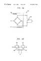
- FIGS. 3A and 3Billustrated are embodiments of bi-directional switches employable in the controller of the present invention. More specifically, FIG. 3A illustrates a first bi-directional switch 310 implemented with a unidirectional switch 320 coupled to a rectifier 330 . The arrangement of the diodes of the rectifier 330 allows the bi-directional switch 310 to conduct and block current in both directions.
- FIG. 3Billustrates a second bi-directional switch 350 implemented by coupling first and second unidirectional switches 360 , 370 such that first and second diodes 365 , 375 , integral to the first and second unidirectional switches 360 , 370 , are facing in opposite directions.
- first and second unidirectional switches 360 , 370are facing in opposite directions.
- other implementations of bi-directional switchesare possible and are well within the broad scope of the present invention.
Landscapes
- Engineering & Computer Science (AREA)
- Power Engineering (AREA)
- Dc-Dc Converters (AREA)
- Inverter Devices (AREA)
Abstract
Description
Claims (21)
Priority Applications (4)
| Application Number | Priority Date | Filing Date | Title |
|---|---|---|---|
| US09/469,693US6201719B1 (en) | 1999-12-22 | 1999-12-22 | Controller for power supply and method of operation thereof |
| EP00310938AEP1126593A2 (en) | 1999-12-22 | 2000-12-08 | Controller for power supply and method of operation thereof |
| CN00135487ACN1301081A (en) | 1999-12-22 | 2000-12-21 | Controller for power supply and operation thereof |
| JP2000389666AJP2001186764A (en) | 1999-12-22 | 2000-12-22 | Power source controller and its operating method |
Applications Claiming Priority (1)
| Application Number | Priority Date | Filing Date | Title |
|---|---|---|---|
| US09/469,693US6201719B1 (en) | 1999-12-22 | 1999-12-22 | Controller for power supply and method of operation thereof |
Publications (1)
| Publication Number | Publication Date |
|---|---|
| US6201719B1true US6201719B1 (en) | 2001-03-13 |
Family
ID=23864742
Family Applications (1)
| Application Number | Title | Priority Date | Filing Date |
|---|---|---|---|
| US09/469,693Expired - LifetimeUS6201719B1 (en) | 1999-12-22 | 1999-12-22 | Controller for power supply and method of operation thereof |
Country Status (4)
| Country | Link |
|---|---|
| US (1) | US6201719B1 (en) |
| EP (1) | EP1126593A2 (en) |
| JP (1) | JP2001186764A (en) |
| CN (1) | CN1301081A (en) |
Cited By (53)
| Publication number | Priority date | Publication date | Assignee | Title |
|---|---|---|---|---|
| US6388905B2 (en)* | 2000-07-04 | 2002-05-14 | Fidelix, Y.K. | Single phase AC-DC converter having a power factor control function |
| US6606257B2 (en)* | 2001-11-05 | 2003-08-12 | Koninklijke Philips Electronics N.V. | Independent regulation of multiple outputs in a soft-switching multiple-output flyback converter |
| US20050088855A1 (en)* | 2001-12-15 | 2005-04-28 | Thomas Kirchmeier | High frequency excitation system |
| US20080002576A1 (en)* | 2006-06-30 | 2008-01-03 | Bugenhagen Michael K | System and method for resetting counters counting network performance information at network communications devices on a packet network |
| US20080002677A1 (en)* | 2006-06-30 | 2008-01-03 | Bugenhagen Michael K | System and method for collecting network performance information |
| US20080005156A1 (en)* | 2006-06-30 | 2008-01-03 | Edwards Stephen K | System and method for managing subscriber usage of a communications network |
| US20080002670A1 (en)* | 2006-06-30 | 2008-01-03 | Bugenhagen Michael K | System and method for adjusting code speed in a transmission path during call set-up due to reduced transmission performance |
| US20080052393A1 (en)* | 2006-08-22 | 2008-02-28 | Mcnaughton James L | System and method for remotely controlling network operators |
| US20080049775A1 (en)* | 2006-08-22 | 2008-02-28 | Morrill Robert J | System and method for monitoring and optimizing network performance with vector performance tables and engines |
| US20080049753A1 (en)* | 2006-08-22 | 2008-02-28 | Heinze John M | System and method for load balancing network resources using a connection admission control engine |
| US20080049632A1 (en)* | 2006-08-22 | 2008-02-28 | Ray Amar N | System and method for adjusting the window size of a TCP packet through remote network elements |
| US20080049650A1 (en)* | 2006-08-22 | 2008-02-28 | Coppage Carl M | System and method for managing radio frequency windows |
| US20080049625A1 (en)* | 2006-08-22 | 2008-02-28 | Edwards Stephen K | System and method for collecting and managing network performance information |
| US20080049748A1 (en)* | 2006-08-22 | 2008-02-28 | Bugenhagen Michael K | System and method for routing communications between packet networks based on intercarrier agreements |
| US20080049757A1 (en)* | 2006-08-22 | 2008-02-28 | Bugenhagen Michael K | System and method for synchronizing counters on an asynchronous packet communications network |
| US20080049638A1 (en)* | 2006-08-22 | 2008-02-28 | Ray Amar N | System and method for monitoring and optimizing network performance with user datagram protocol network performance information packets |
| US20080049927A1 (en)* | 2006-08-22 | 2008-02-28 | Wiley William L | System and method for establishing a call being received by a trunk on a packet network |
| US20080049649A1 (en)* | 2006-08-22 | 2008-02-28 | Kozisek Steven E | System and method for selecting an access point |
| US20080049787A1 (en)* | 2006-08-22 | 2008-02-28 | Mcnaughton James L | System and method for controlling network bandwidth with a connection admission control engine |
| US20080049630A1 (en)* | 2006-08-22 | 2008-02-28 | Kozisek Steven E | System and method for monitoring and optimizing network performance to a wireless device |
| US20080049626A1 (en)* | 2006-08-22 | 2008-02-28 | Bugenhagen Michael K | System and method for communicating network performance information over a packet network |
| US20080052401A1 (en)* | 2006-08-22 | 2008-02-28 | Bugenhagen Michael K | Pin-hole firewall for communicating data packets on a packet network |
| US20080049777A1 (en)* | 2006-08-22 | 2008-02-28 | Morrill Robert J | System and method for using distributed network performance information tables to manage network communications |
| US20080049641A1 (en)* | 2006-08-22 | 2008-02-28 | Edwards Stephen K | System and method for displaying a graph representative of network performance over a time period |
| US20080049631A1 (en)* | 2006-08-22 | 2008-02-28 | Morrill Robert J | System and method for monitoring interlayer devices and optimizing network performance |
| US20080049745A1 (en)* | 2006-08-22 | 2008-02-28 | Edwards Stephen K | System and method for enabling reciprocal billing for different types of communications over a packet network |
| US20080052206A1 (en)* | 2006-08-22 | 2008-02-28 | Edwards Stephen K | System and method for billing users for communicating over a communications network |
| US20080049629A1 (en)* | 2006-08-22 | 2008-02-28 | Morrill Robert J | System and method for monitoring data link layer devices and optimizing interlayer network performance |
| US20080095173A1 (en)* | 2006-10-19 | 2008-04-24 | Embarq Holdings Company, Llc | System and method for monitoring the connection of an end-user to a remote network |
| US20080095049A1 (en)* | 2006-10-19 | 2008-04-24 | Embarq Holdings Company, Llc | System and method for establishing a communications session with an end-user based on the state of a network connection |
| US20080279183A1 (en)* | 2006-06-30 | 2008-11-13 | Wiley William L | System and method for call routing based on transmission performance of a packet network |
| WO2009079440A1 (en)* | 2007-12-17 | 2009-06-25 | Lawson Labs, Inc. | Gate-charge retaining switch |
| US20090196072A1 (en)* | 2007-12-03 | 2009-08-06 | Zhong Ye | Phase-shifted dual-bridge DC/DC converter with wide-range ZVS and zero circulating current |
| US20090257350A1 (en)* | 2008-04-09 | 2009-10-15 | Embarq Holdings Company, Llc | System and method for using network performance information to determine improved measures of path states |
| US20100026276A1 (en)* | 2008-07-30 | 2010-02-04 | Northrop Grumman Systems Corporation | Method and Apparatus for Fast Fault Detection |
| US20100085887A1 (en)* | 2006-08-22 | 2010-04-08 | Embarq Holdings Company, Llc | System and method for adjusting the window size of a tcp packet through network elements |
| US20100208611A1 (en)* | 2007-05-31 | 2010-08-19 | Embarq Holdings Company, Llc | System and method for modifying network traffic |
| US7808918B2 (en) | 2006-08-22 | 2010-10-05 | Embarq Holdings Company, Llc | System and method for dynamically shaping network traffic |
| US7843831B2 (en) | 2006-08-22 | 2010-11-30 | Embarq Holdings Company Llc | System and method for routing data on a packet network |
| US8107366B2 (en) | 2006-08-22 | 2012-01-31 | Embarq Holdings Company, LP | System and method for using centralized network performance tables to manage network communications |
| US8189468B2 (en) | 2006-10-25 | 2012-05-29 | Embarq Holdings, Company, LLC | System and method for regulating messages between networks |
| US8223655B2 (en) | 2006-08-22 | 2012-07-17 | Embarq Holdings Company, Llc | System and method for provisioning resources of a packet network based on collected network performance information |
| US8407765B2 (en) | 2006-08-22 | 2013-03-26 | Centurylink Intellectual Property Llc | System and method for restricting access to network performance information tables |
| US8531954B2 (en) | 2006-08-22 | 2013-09-10 | Centurylink Intellectual Property Llc | System and method for handling reservation requests with a connection admission control engine |
| US8549405B2 (en) | 2006-08-22 | 2013-10-01 | Centurylink Intellectual Property Llc | System and method for displaying a graphical representation of a network to identify nodes and node segments on the network that are not operating normally |
| US8576722B2 (en) | 2006-08-22 | 2013-11-05 | Centurylink Intellectual Property Llc | System and method for modifying connectivity fault management packets |
| US8619600B2 (en) | 2006-08-22 | 2013-12-31 | Centurylink Intellectual Property Llc | System and method for establishing calls over a call path having best path metrics |
| US8743703B2 (en) | 2006-08-22 | 2014-06-03 | Centurylink Intellectual Property Llc | System and method for tracking application resource usage |
| US8750158B2 (en) | 2006-08-22 | 2014-06-10 | Centurylink Intellectual Property Llc | System and method for differentiated billing |
| US9094257B2 (en) | 2006-06-30 | 2015-07-28 | Centurylink Intellectual Property Llc | System and method for selecting a content delivery network |
| US9479341B2 (en) | 2006-08-22 | 2016-10-25 | Centurylink Intellectual Property Llc | System and method for initiating diagnostics on a packet network node |
| US20240022167A1 (en)* | 2022-07-15 | 2024-01-18 | Delta Electronics (Shanghai) Co.,Ltd. | Resonant converter, and controlling method for the same |
| CN120658117A (en)* | 2025-08-18 | 2025-09-16 | 西安锐泽克斯光电科技有限公司 | Intrinsic safety type phase shift resonance full-bridge circuit, charging equipment and system |
Families Citing this family (2)
| Publication number | Priority date | Publication date | Assignee | Title |
|---|---|---|---|---|
| CN107453614A (en)* | 2017-09-15 | 2017-12-08 | 肇庆市锐高电子有限公司 | Full-bridge synchronous rectification circuit |
| JP7183919B2 (en)* | 2019-03-29 | 2022-12-06 | Tdk株式会社 | switching power supply |
Citations (1)
| Publication number | Priority date | Publication date | Assignee | Title |
|---|---|---|---|---|
| US5121314A (en)* | 1991-02-04 | 1992-06-09 | Maxwell Laboratories | Bi-mode high voltage resonant power supply and method |
- 1999
- 1999-12-22USUS09/469,693patent/US6201719B1/ennot_activeExpired - Lifetime
- 2000
- 2000-12-08EPEP00310938Apatent/EP1126593A2/ennot_activeWithdrawn
- 2000-12-21CNCN00135487Apatent/CN1301081A/enactivePending
- 2000-12-22JPJP2000389666Apatent/JP2001186764A/enactivePending
Patent Citations (1)
| Publication number | Priority date | Publication date | Assignee | Title |
|---|---|---|---|---|
| US5121314A (en)* | 1991-02-04 | 1992-06-09 | Maxwell Laboratories | Bi-mode high voltage resonant power supply and method |
Non-Patent Citations (3)
| Title |
|---|
| "A Novel Soft-Switching Converter with Reduced Filter Requirement" by Rajapandian Ayyanar and Ned Mohan: Sep. 1998 Workshop Presentation: 20 pg. No Page #'s. |
| "A Novel Soft-Switching DC-DC Converter with Wide ZVS-Range and Reduced Filter Requirement" by Rajapandian Ayyanar and Ned Mohan: 1999 IEEE; pp. 433-438. No Month. |
| "Full-Load-Range-ZVS Hybrid DC-DC Converter with Two Full-Bridges for High-Power Battery Charging" by Rajapandian Ayyanar and Ned Mohan: 1999 IEEE; 8 pg. No Page #'s No Month. |
Cited By (146)
| Publication number | Priority date | Publication date | Assignee | Title |
|---|---|---|---|---|
| US6388905B2 (en)* | 2000-07-04 | 2002-05-14 | Fidelix, Y.K. | Single phase AC-DC converter having a power factor control function |
| US6606257B2 (en)* | 2001-11-05 | 2003-08-12 | Koninklijke Philips Electronics N.V. | Independent regulation of multiple outputs in a soft-switching multiple-output flyback converter |
| US7440301B2 (en) | 2001-12-15 | 2008-10-21 | Huettinger Elektronik Gmbh & Co. Kg | High frequency excitation system |
| US20050088855A1 (en)* | 2001-12-15 | 2005-04-28 | Thomas Kirchmeier | High frequency excitation system |
| US7161818B2 (en)* | 2001-12-15 | 2007-01-09 | Huttinger Elektronik Gmbh + Co. Kg | High frequency excitation system |
| US20070085133A1 (en)* | 2001-12-15 | 2007-04-19 | Huettinger Elektronik Gmbh + Co. Kg | High frequency excitation system |
| US20090015314A1 (en)* | 2001-12-15 | 2009-01-15 | Huettinger Elektronik Gmbh + Co. Kg | High frequency excitation system |
| US7652901B2 (en) | 2001-12-15 | 2010-01-26 | Huettinger Elektronik Gmbh + Co. Kg | High frequency excitation system |
| US9154634B2 (en) | 2006-06-30 | 2015-10-06 | Centurylink Intellectual Property Llc | System and method for managing network communications |
| US8717911B2 (en) | 2006-06-30 | 2014-05-06 | Centurylink Intellectual Property Llc | System and method for collecting network performance information |
| US20080002670A1 (en)* | 2006-06-30 | 2008-01-03 | Bugenhagen Michael K | System and method for adjusting code speed in a transmission path during call set-up due to reduced transmission performance |
| US10560494B2 (en) | 2006-06-30 | 2020-02-11 | Centurylink Intellectual Property Llc | Managing voice over internet protocol (VoIP) communications |
| US10230788B2 (en) | 2006-06-30 | 2019-03-12 | Centurylink Intellectual Property Llc | System and method for selecting a content delivery network |
| US9838440B2 (en) | 2006-06-30 | 2017-12-05 | Centurylink Intellectual Property Llc | Managing voice over internet protocol (VoIP) communications |
| US9749399B2 (en) | 2006-06-30 | 2017-08-29 | Centurylink Intellectual Property Llc | System and method for selecting a content delivery network |
| US9549004B2 (en) | 2006-06-30 | 2017-01-17 | Centurylink Intellectual Property Llc | System and method for re-routing calls |
| US20080002716A1 (en)* | 2006-06-30 | 2008-01-03 | Wiley William L | System and method for selecting network egress |
| US9118583B2 (en) | 2006-06-30 | 2015-08-25 | Centurylink Intellectual Property Llc | System and method for re-routing calls |
| US9094257B2 (en) | 2006-06-30 | 2015-07-28 | Centurylink Intellectual Property Llc | System and method for selecting a content delivery network |
| US9054915B2 (en) | 2006-06-30 | 2015-06-09 | Centurylink Intellectual Property Llc | System and method for adjusting CODEC speed in a transmission path during call set-up due to reduced transmission performance |
| US8976665B2 (en) | 2006-06-30 | 2015-03-10 | Centurylink Intellectual Property Llc | System and method for re-routing calls |
| US20080002676A1 (en)* | 2006-06-30 | 2008-01-03 | Wiley William L | System and method for routing calls if potential call paths are impaired or congested |
| US8570872B2 (en) | 2006-06-30 | 2013-10-29 | Centurylink Intellectual Property Llc | System and method for selecting network ingress and egress |
| US8488447B2 (en) | 2006-06-30 | 2013-07-16 | Centurylink Intellectual Property Llc | System and method for adjusting code speed in a transmission path during call set-up due to reduced transmission performance |
| US8477614B2 (en) | 2006-06-30 | 2013-07-02 | Centurylink Intellectual Property Llc | System and method for routing calls if potential call paths are impaired or congested |
| US20080005156A1 (en)* | 2006-06-30 | 2008-01-03 | Edwards Stephen K | System and method for managing subscriber usage of a communications network |
| US8184549B2 (en) | 2006-06-30 | 2012-05-22 | Embarq Holdings Company, LLP | System and method for selecting network egress |
| US8000318B2 (en) | 2006-06-30 | 2011-08-16 | Embarq Holdings Company, Llc | System and method for call routing based on transmission performance of a packet network |
| US7948909B2 (en) | 2006-06-30 | 2011-05-24 | Embarq Holdings Company, Llc | System and method for resetting counters counting network performance information at network communications devices on a packet network |
| US7765294B2 (en) | 2006-06-30 | 2010-07-27 | Embarq Holdings Company, Llc | System and method for managing subscriber usage of a communications network |
| US20080002677A1 (en)* | 2006-06-30 | 2008-01-03 | Bugenhagen Michael K | System and method for collecting network performance information |
| US20080002576A1 (en)* | 2006-06-30 | 2008-01-03 | Bugenhagen Michael K | System and method for resetting counters counting network performance information at network communications devices on a packet network |
| US20080279183A1 (en)* | 2006-06-30 | 2008-11-13 | Wiley William L | System and method for call routing based on transmission performance of a packet network |
| US8224255B2 (en) | 2006-08-22 | 2012-07-17 | Embarq Holdings Company, Llc | System and method for managing radio frequency windows |
| US8531954B2 (en) | 2006-08-22 | 2013-09-10 | Centurylink Intellectual Property Llc | System and method for handling reservation requests with a connection admission control engine |
| US20080052393A1 (en)* | 2006-08-22 | 2008-02-28 | Mcnaughton James L | System and method for remotely controlling network operators |
| US20080049629A1 (en)* | 2006-08-22 | 2008-02-28 | Morrill Robert J | System and method for monitoring data link layer devices and optimizing interlayer network performance |
| US20080052206A1 (en)* | 2006-08-22 | 2008-02-28 | Edwards Stephen K | System and method for billing users for communicating over a communications network |
| US10469385B2 (en) | 2006-08-22 | 2019-11-05 | Centurylink Intellectual Property Llc | System and method for improving network performance using a connection admission control engine |
| US10298476B2 (en) | 2006-08-22 | 2019-05-21 | Centurylink Intellectual Property Llc | System and method for tracking application resource usage |
| US20080049775A1 (en)* | 2006-08-22 | 2008-02-28 | Morrill Robert J | System and method for monitoring and optimizing network performance with vector performance tables and engines |
| US10075351B2 (en) | 2006-08-22 | 2018-09-11 | Centurylink Intellectual Property Llc | System and method for improving network performance |
| US20080049745A1 (en)* | 2006-08-22 | 2008-02-28 | Edwards Stephen K | System and method for enabling reciprocal billing for different types of communications over a packet network |
| US9992348B2 (en) | 2006-08-22 | 2018-06-05 | Century Link Intellectual Property LLC | System and method for establishing a call on a packet network |
| US20100085887A1 (en)* | 2006-08-22 | 2010-04-08 | Embarq Holdings Company, Llc | System and method for adjusting the window size of a tcp packet through network elements |
| US20080049631A1 (en)* | 2006-08-22 | 2008-02-28 | Morrill Robert J | System and method for monitoring interlayer devices and optimizing network performance |
| US9929923B2 (en) | 2006-08-22 | 2018-03-27 | Centurylink Intellectual Property Llc | System and method for provisioning resources of a packet network based on collected network performance information |
| US7808918B2 (en) | 2006-08-22 | 2010-10-05 | Embarq Holdings Company, Llc | System and method for dynamically shaping network traffic |
| US7843831B2 (en) | 2006-08-22 | 2010-11-30 | Embarq Holdings Company Llc | System and method for routing data on a packet network |
| US20110032821A1 (en)* | 2006-08-22 | 2011-02-10 | Morrill Robert J | System and method for routing data on a packet network |
| US7889660B2 (en) | 2006-08-22 | 2011-02-15 | Embarq Holdings Company, Llc | System and method for synchronizing counters on an asynchronous packet communications network |
| US7940735B2 (en) | 2006-08-22 | 2011-05-10 | Embarq Holdings Company, Llc | System and method for selecting an access point |
| US20080049641A1 (en)* | 2006-08-22 | 2008-02-28 | Edwards Stephen K | System and method for displaying a graph representative of network performance over a time period |
| US20080049777A1 (en)* | 2006-08-22 | 2008-02-28 | Morrill Robert J | System and method for using distributed network performance information tables to manage network communications |
| US8015294B2 (en) | 2006-08-22 | 2011-09-06 | Embarq Holdings Company, LP | Pin-hole firewall for communicating data packets on a packet network |
| US8040811B2 (en) | 2006-08-22 | 2011-10-18 | Embarq Holdings Company, Llc | System and method for collecting and managing network performance information |
| US8064391B2 (en) | 2006-08-22 | 2011-11-22 | Embarq Holdings Company, Llc | System and method for monitoring and optimizing network performance to a wireless device |
| US20080049753A1 (en)* | 2006-08-22 | 2008-02-28 | Heinze John M | System and method for load balancing network resources using a connection admission control engine |
| US8098579B2 (en)* | 2006-08-22 | 2012-01-17 | Embarq Holdings Company, LP | System and method for adjusting the window size of a TCP packet through remote network elements |
| US8102770B2 (en) | 2006-08-22 | 2012-01-24 | Embarq Holdings Company, LP | System and method for monitoring and optimizing network performance with vector performance tables and engines |
| US8107366B2 (en) | 2006-08-22 | 2012-01-31 | Embarq Holdings Company, LP | System and method for using centralized network performance tables to manage network communications |
| US9832090B2 (en) | 2006-08-22 | 2017-11-28 | Centurylink Intellectual Property Llc | System, method for compiling network performancing information for communications with customer premise equipment |
| US8125897B2 (en) | 2006-08-22 | 2012-02-28 | Embarq Holdings Company Lp | System and method for monitoring and optimizing network performance with user datagram protocol network performance information packets |
| US8130793B2 (en) | 2006-08-22 | 2012-03-06 | Embarq Holdings Company, Llc | System and method for enabling reciprocal billing for different types of communications over a packet network |
| US8144586B2 (en) | 2006-08-22 | 2012-03-27 | Embarq Holdings Company, Llc | System and method for controlling network bandwidth with a connection admission control engine |
| US8144587B2 (en) | 2006-08-22 | 2012-03-27 | Embarq Holdings Company, Llc | System and method for load balancing network resources using a connection admission control engine |
| US20080052401A1 (en)* | 2006-08-22 | 2008-02-28 | Bugenhagen Michael K | Pin-hole firewall for communicating data packets on a packet network |
| US9813320B2 (en) | 2006-08-22 | 2017-11-07 | Centurylink Intellectual Property Llc | System and method for generating a graphical user interface representative of network performance |
| US9806972B2 (en) | 2006-08-22 | 2017-10-31 | Centurylink Intellectual Property Llc | System and method for monitoring and altering performance of a packet network |
| US8194555B2 (en) | 2006-08-22 | 2012-06-05 | Embarq Holdings Company, Llc | System and method for using distributed network performance information tables to manage network communications |
| US8199653B2 (en) | 2006-08-22 | 2012-06-12 | Embarq Holdings Company, Llc | System and method for communicating network performance information over a packet network |
| US8213366B2 (en) | 2006-08-22 | 2012-07-03 | Embarq Holdings Company, Llc | System and method for monitoring and optimizing network performance to a wireless device |
| US20080049626A1 (en)* | 2006-08-22 | 2008-02-28 | Bugenhagen Michael K | System and method for communicating network performance information over a packet network |
| US8223654B2 (en) | 2006-08-22 | 2012-07-17 | Embarq Holdings Company, Llc | Application-specific integrated circuit for monitoring and optimizing interlayer network performance |
| US8223655B2 (en) | 2006-08-22 | 2012-07-17 | Embarq Holdings Company, Llc | System and method for provisioning resources of a packet network based on collected network performance information |
| US8228791B2 (en) | 2006-08-22 | 2012-07-24 | Embarq Holdings Company, Llc | System and method for routing communications between packet networks based on intercarrier agreements |
| US8238253B2 (en) | 2006-08-22 | 2012-08-07 | Embarq Holdings Company, Llc | System and method for monitoring interlayer devices and optimizing network performance |
| US8274905B2 (en) | 2006-08-22 | 2012-09-25 | Embarq Holdings Company, Llc | System and method for displaying a graph representative of network performance over a time period |
| US20080049632A1 (en)* | 2006-08-22 | 2008-02-28 | Ray Amar N | System and method for adjusting the window size of a TCP packet through remote network elements |
| US8307065B2 (en) | 2006-08-22 | 2012-11-06 | Centurylink Intellectual Property Llc | System and method for remotely controlling network operators |
| US8358580B2 (en) | 2006-08-22 | 2013-01-22 | Centurylink Intellectual Property Llc | System and method for adjusting the window size of a TCP packet through network elements |
| US8374090B2 (en) | 2006-08-22 | 2013-02-12 | Centurylink Intellectual Property Llc | System and method for routing data on a packet network |
| US8407765B2 (en) | 2006-08-22 | 2013-03-26 | Centurylink Intellectual Property Llc | System and method for restricting access to network performance information tables |
| US8472326B2 (en) | 2006-08-22 | 2013-06-25 | Centurylink Intellectual Property Llc | System and method for monitoring interlayer devices and optimizing network performance |
| US20080049630A1 (en)* | 2006-08-22 | 2008-02-28 | Kozisek Steven E | System and method for monitoring and optimizing network performance to a wireless device |
| US8488495B2 (en) | 2006-08-22 | 2013-07-16 | Centurylink Intellectual Property Llc | System and method for routing communications between packet networks based on real time pricing |
| US20080049787A1 (en)* | 2006-08-22 | 2008-02-28 | Mcnaughton James L | System and method for controlling network bandwidth with a connection admission control engine |
| US8509082B2 (en) | 2006-08-22 | 2013-08-13 | Centurylink Intellectual Property Llc | System and method for load balancing network resources using a connection admission control engine |
| US9712445B2 (en) | 2006-08-22 | 2017-07-18 | Centurylink Intellectual Property Llc | System and method for routing data on a packet network |
| US8520603B2 (en) | 2006-08-22 | 2013-08-27 | Centurylink Intellectual Property Llc | System and method for monitoring and optimizing network performance to a wireless device |
| US9661514B2 (en) | 2006-08-22 | 2017-05-23 | Centurylink Intellectual Property Llc | System and method for adjusting communication parameters |
| US8537695B2 (en) | 2006-08-22 | 2013-09-17 | Centurylink Intellectual Property Llc | System and method for establishing a call being received by a trunk on a packet network |
| US8549405B2 (en) | 2006-08-22 | 2013-10-01 | Centurylink Intellectual Property Llc | System and method for displaying a graphical representation of a network to identify nodes and node segments on the network that are not operating normally |
| US20080049649A1 (en)* | 2006-08-22 | 2008-02-28 | Kozisek Steven E | System and method for selecting an access point |
| US8576722B2 (en) | 2006-08-22 | 2013-11-05 | Centurylink Intellectual Property Llc | System and method for modifying connectivity fault management packets |
| US8619820B2 (en) | 2006-08-22 | 2013-12-31 | Centurylink Intellectual Property Llc | System and method for enabling communications over a number of packet networks |
| US8619600B2 (en) | 2006-08-22 | 2013-12-31 | Centurylink Intellectual Property Llc | System and method for establishing calls over a call path having best path metrics |
| US8619596B2 (en) | 2006-08-22 | 2013-12-31 | Centurylink Intellectual Property Llc | System and method for using centralized network performance tables to manage network communications |
| US8670313B2 (en) | 2006-08-22 | 2014-03-11 | Centurylink Intellectual Property Llc | System and method for adjusting the window size of a TCP packet through network elements |
| US8687614B2 (en) | 2006-08-22 | 2014-04-01 | Centurylink Intellectual Property Llc | System and method for adjusting radio frequency parameters |
| US20080049927A1 (en)* | 2006-08-22 | 2008-02-28 | Wiley William L | System and method for establishing a call being received by a trunk on a packet network |
| US8743703B2 (en) | 2006-08-22 | 2014-06-03 | Centurylink Intellectual Property Llc | System and method for tracking application resource usage |
| US8743700B2 (en) | 2006-08-22 | 2014-06-03 | Centurylink Intellectual Property Llc | System and method for provisioning resources of a packet network based on collected network performance information |
| US8750158B2 (en) | 2006-08-22 | 2014-06-10 | Centurylink Intellectual Property Llc | System and method for differentiated billing |
| US8811160B2 (en) | 2006-08-22 | 2014-08-19 | Centurylink Intellectual Property Llc | System and method for routing data on a packet network |
| US9660917B2 (en) | 2006-08-22 | 2017-05-23 | Centurylink Intellectual Property Llc | System and method for remotely controlling network operators |
| US20080049638A1 (en)* | 2006-08-22 | 2008-02-28 | Ray Amar N | System and method for monitoring and optimizing network performance with user datagram protocol network performance information packets |
| US9014204B2 (en) | 2006-08-22 | 2015-04-21 | Centurylink Intellectual Property Llc | System and method for managing network communications |
| US9042370B2 (en) | 2006-08-22 | 2015-05-26 | Centurylink Intellectual Property Llc | System and method for establishing calls over a call path having best path metrics |
| US9054986B2 (en) | 2006-08-22 | 2015-06-09 | Centurylink Intellectual Property Llc | System and method for enabling communications over a number of packet networks |
| US20080049757A1 (en)* | 2006-08-22 | 2008-02-28 | Bugenhagen Michael K | System and method for synchronizing counters on an asynchronous packet communications network |
| US20080049748A1 (en)* | 2006-08-22 | 2008-02-28 | Bugenhagen Michael K | System and method for routing communications between packet networks based on intercarrier agreements |
| US9094261B2 (en) | 2006-08-22 | 2015-07-28 | Centurylink Intellectual Property Llc | System and method for establishing a call being received by a trunk on a packet network |
| US9112734B2 (en) | 2006-08-22 | 2015-08-18 | Centurylink Intellectual Property Llc | System and method for generating a graphical user interface representative of network performance |
| US20080049769A1 (en)* | 2006-08-22 | 2008-02-28 | Bugenhagen Michael K | Application-specific integrated circuit for monitoring and optimizing interlayer network performance |
| US9621361B2 (en) | 2006-08-22 | 2017-04-11 | Centurylink Intellectual Property Llc | Pin-hole firewall for communicating data packets on a packet network |
| US20080049625A1 (en)* | 2006-08-22 | 2008-02-28 | Edwards Stephen K | System and method for collecting and managing network performance information |
| US9225609B2 (en) | 2006-08-22 | 2015-12-29 | Centurylink Intellectual Property Llc | System and method for remotely controlling network operators |
| US9225646B2 (en) | 2006-08-22 | 2015-12-29 | Centurylink Intellectual Property Llc | System and method for improving network performance using a connection admission control engine |
| US9240906B2 (en) | 2006-08-22 | 2016-01-19 | Centurylink Intellectual Property Llc | System and method for monitoring and altering performance of a packet network |
| US9241277B2 (en) | 2006-08-22 | 2016-01-19 | Centurylink Intellectual Property Llc | System and method for monitoring and optimizing network performance to a wireless device |
| US9241271B2 (en) | 2006-08-22 | 2016-01-19 | Centurylink Intellectual Property Llc | System and method for restricting access to network performance information |
| US9253661B2 (en) | 2006-08-22 | 2016-02-02 | Centurylink Intellectual Property Llc | System and method for modifying connectivity fault management packets |
| US9479341B2 (en) | 2006-08-22 | 2016-10-25 | Centurylink Intellectual Property Llc | System and method for initiating diagnostics on a packet network node |
| US9602265B2 (en) | 2006-08-22 | 2017-03-21 | Centurylink Intellectual Property Llc | System and method for handling communications requests |
| US20080049650A1 (en)* | 2006-08-22 | 2008-02-28 | Coppage Carl M | System and method for managing radio frequency windows |
| US8194643B2 (en) | 2006-10-19 | 2012-06-05 | Embarq Holdings Company, Llc | System and method for monitoring the connection of an end-user to a remote network |
| US20080095173A1 (en)* | 2006-10-19 | 2008-04-24 | Embarq Holdings Company, Llc | System and method for monitoring the connection of an end-user to a remote network |
| US20080095049A1 (en)* | 2006-10-19 | 2008-04-24 | Embarq Holdings Company, Llc | System and method for establishing a communications session with an end-user based on the state of a network connection |
| US8289965B2 (en) | 2006-10-19 | 2012-10-16 | Embarq Holdings Company, Llc | System and method for establishing a communications session with an end-user based on the state of a network connection |
| US9521150B2 (en) | 2006-10-25 | 2016-12-13 | Centurylink Intellectual Property Llc | System and method for automatically regulating messages between networks |
| US8189468B2 (en) | 2006-10-25 | 2012-05-29 | Embarq Holdings, Company, LLC | System and method for regulating messages between networks |
| US20100208611A1 (en)* | 2007-05-31 | 2010-08-19 | Embarq Holdings Company, Llc | System and method for modifying network traffic |
| US8111692B2 (en) | 2007-05-31 | 2012-02-07 | Embarq Holdings Company Llc | System and method for modifying network traffic |
| US9118259B2 (en)* | 2007-12-03 | 2015-08-25 | Texas Instruments Incorporated | Phase-shifted dual-bridge DC/DC converter with wide-range ZVS and zero circulating current |
| US20090196072A1 (en)* | 2007-12-03 | 2009-08-06 | Zhong Ye | Phase-shifted dual-bridge DC/DC converter with wide-range ZVS and zero circulating current |
| US20090167412A1 (en)* | 2007-12-17 | 2009-07-02 | Lawson Labs, Inc. | Gate-charge retaining switch |
| WO2009079440A1 (en)* | 2007-12-17 | 2009-06-25 | Lawson Labs, Inc. | Gate-charge retaining switch |
| US8068425B2 (en) | 2008-04-09 | 2011-11-29 | Embarq Holdings Company, Llc | System and method for using network performance information to determine improved measures of path states |
| US8879391B2 (en) | 2008-04-09 | 2014-11-04 | Centurylink Intellectual Property Llc | System and method for using network derivations to determine path states |
| US20090257350A1 (en)* | 2008-04-09 | 2009-10-15 | Embarq Holdings Company, Llc | System and method for using network performance information to determine improved measures of path states |
| US20100026276A1 (en)* | 2008-07-30 | 2010-02-04 | Northrop Grumman Systems Corporation | Method and Apparatus for Fast Fault Detection |
| US8513951B2 (en)* | 2008-07-30 | 2013-08-20 | Northrop Grumman Systems Corporation | Method and apparatus for fast fault detection |
| US20240022167A1 (en)* | 2022-07-15 | 2024-01-18 | Delta Electronics (Shanghai) Co.,Ltd. | Resonant converter, and controlling method for the same |
| US12401273B2 (en)* | 2022-07-15 | 2025-08-26 | Delta Electronics (Shanghai) Co., Ltd. | Resonant converter, and controlling method for the same |
| CN120658117A (en)* | 2025-08-18 | 2025-09-16 | 西安锐泽克斯光电科技有限公司 | Intrinsic safety type phase shift resonance full-bridge circuit, charging equipment and system |
Also Published As
| Publication number | Publication date |
|---|---|
| CN1301081A (en) | 2001-06-27 |
| JP2001186764A (en) | 2001-07-06 |
| EP1126593A2 (en) | 2001-08-22 |
Similar Documents
| Publication | Publication Date | Title |
|---|---|---|
| US6201719B1 (en) | Controller for power supply and method of operation thereof | |
| US11025172B2 (en) | Three-level modulation for wide output voltage range isolated DC/DC converters | |
| US10284099B2 (en) | Hybrid power converters combining switched-capacitor and transformer-based stages | |
| US10833594B2 (en) | System and method of controlling a power converter having an LC tank coupled between a switching network and a transformer winding | |
| US6353547B1 (en) | Three-level soft-switched converters | |
| Ayyanar et al. | Novel soft-switching DC-DC converter with full ZVS-range and reduced filter requirement. I. Regulated-output applications | |
| Jang et al. | A new family of full-bridge ZVS converters | |
| US9812977B2 (en) | Resonant converters with an improved voltage regulation range | |
| US6356462B1 (en) | Soft-switched full-bridge converters | |
| US9263960B2 (en) | Power converters for wide input or output voltage range and control methods thereof | |
| US7218081B2 (en) | Power system having multiple power converters with reduced switching loss | |
| US9118259B2 (en) | Phase-shifted dual-bridge DC/DC converter with wide-range ZVS and zero circulating current | |
| US6807073B1 (en) | Switching type power converter circuit and method for use therein | |
| JP7439671B2 (en) | Switching power supplies and power supply systems | |
| US5471376A (en) | Low-loss active voltage-clamp circuit for single-ended forward PWM converter | |
| US6344768B1 (en) | Full-bridge DC-to-DC converter having an unipolar gate drive | |
| US5057990A (en) | Bidirectional switching power apparatus with AC or DC output | |
| US6560127B2 (en) | Power conversion circuit having improved zero voltage switching | |
| US6320764B1 (en) | Regulation circuit for a power converter and method of operation thereof | |
| US6590791B1 (en) | High input voltage, high efficiency, fast transient voltage regulator module (VRM) | |
| EP2975753B1 (en) | A three-level converter | |
| US6038147A (en) | Power supply employing circulating capacitor and method of operation thereof | |
| US7050309B2 (en) | Power converter with output inductance | |
| US6178098B1 (en) | Phase-shifted post-regulator, method of operation thereof and power converter employing the same | |
| Ayyanar et al. | A novel soft-switching DC-DC converter with wide ZVS-range and reduced filter requirement |
Legal Events
| Date | Code | Title | Description |
|---|---|---|---|
| AS | Assignment | Owner name:LUCENT TECHNOLOGIES, INC., NEW JERSEY Free format text:ASSIGNMENT OF ASSIGNORS INTEREST;ASSIGNORS:HE, JIN;JACOBS, MARK E.;REEL/FRAME:010626/0684 Effective date:20000307 | |
| STCF | Information on status: patent grant | Free format text:PATENTED CASE | |
| FEPP | Fee payment procedure | Free format text:PAYOR NUMBER ASSIGNED (ORIGINAL EVENT CODE: ASPN); ENTITY STATUS OF PATENT OWNER: LARGE ENTITY | |
| FPAY | Fee payment | Year of fee payment:4 | |
| AS | Assignment | Owner name:TYCO ELECTRONICS LOGISTICS A.G., SWITZERLAND Free format text:ASSIGNMENT OF ASSIGNORS INTEREST;ASSIGNOR:LUCENT TECHNOLOGIES INC.;REEL/FRAME:020102/0223 Effective date:20001229 | |
| AS | Assignment | Owner name:TYCO ELECTRONICS LOGISTICS A.G., SWITZERLAND Free format text:ASSIGNMENT OF ASSIGNORS INTEREST;ASSIGNOR:LUCENT TECHNOLOGIES INC.;REEL/FRAME:020112/0001 Effective date:20001229 | |
| AS | Assignment | Owner name:LINEAGE OVERSEAS CORP., DELAWARE Free format text:ASSIGNMENT OF ASSIGNORS INTEREST;ASSIGNOR:TYCO ELECTRONICS LOGISTICS AG;REEL/FRAME:020609/0580 Effective date:20080228 Owner name:LINEAGE POWER CORPORATION, TEXAS Free format text:ASSIGNMENT OF ASSIGNORS INTEREST;ASSIGNOR:LINEAGE OVERSEAS CORP.;REEL/FRAME:020582/0184 Effective date:20080228 | |
| FPAY | Fee payment | Year of fee payment:8 | |
| AS | Assignment | Owner name:WELLS FARGO FOOTHILL, LLC, AS AGENT, CALIFORNIA Free format text:SECURITY AGREEMENT;ASSIGNOR:LINEAGE POWER CORPORATION;REEL/FRAME:021876/0066 Effective date:20081121 Owner name:WELLS FARGO FOOTHILL, LLC, AS AGENT,CALIFORNIA Free format text:SECURITY AGREEMENT;ASSIGNOR:LINEAGE POWER CORPORATION;REEL/FRAME:021876/0066 Effective date:20081121 | |
| AS | Assignment | Owner name:LINEAGE POWER CORPORATION, TEXAS Free format text:PATENT RELEASE AND REASSIGNMENT;ASSIGNOR:WELLS FARGO CAPITAL FINANCE, LLC;REEL/FRAME:027934/0566 Effective date:20110228 | |
| FPAY | Fee payment | Year of fee payment:12 | |
| AS | Assignment | Owner name:GE POWER ELECTRONICS, INC., TEXAS Free format text:CHANGE OF NAME;ASSIGNOR:LINEAGE POWER CORPORATION;REEL/FRAME:045581/0581 Effective date:20120101 | |
| AS | Assignment | Owner name:ABB SCHWEIZ AG, SWITZERLAND Free format text:ASSIGNMENT OF ASSIGNORS INTEREST;ASSIGNOR:GE POWER ELECTRONICS, INC.;REEL/FRAME:050207/0076 Effective date:20180813 | |
| AS | Assignment | Owner name:ABB POWER ELECTRONICS INC., TEXAS Free format text:ASSIGNMENT OF ASSIGNORS INTEREST;ASSIGNOR:ABB SCHWEIZ AG;REEL/FRAME:052430/0136 Effective date:20200207 |