US6200696B1 - Internal reforming fuel cell assembly with simplified fuel feed - Google Patents
Internal reforming fuel cell assembly with simplified fuel feedDownload PDFInfo
- Publication number
- US6200696B1 US6200696B1US09/251,196US25119699AUS6200696B1US 6200696 B1US6200696 B1US 6200696B1US 25119699 AUS25119699 AUS 25119699AUS 6200696 B1US6200696 B1US 6200696B1
- Authority
- US
- United States
- Prior art keywords
- fuel
- reformer
- fuel cell
- accordance
- cell assembly
- Prior art date
- Legal status (The legal status is an assumption and is not a legal conclusion. Google has not performed a legal analysis and makes no representation as to the accuracy of the status listed.)
- Expired - Lifetime
Links
Images


Classifications
- H—ELECTRICITY
- H01—ELECTRIC ELEMENTS
- H01M—PROCESSES OR MEANS, e.g. BATTERIES, FOR THE DIRECT CONVERSION OF CHEMICAL ENERGY INTO ELECTRICAL ENERGY
- H01M8/00—Fuel cells; Manufacture thereof
- H01M8/06—Combination of fuel cells with means for production of reactants or for treatment of residues
- H01M8/0606—Combination of fuel cells with means for production of reactants or for treatment of residues with means for production of gaseous reactants
- H01M8/0612—Combination of fuel cells with means for production of reactants or for treatment of residues with means for production of gaseous reactants from carbon-containing material
- H01M8/0625—Combination of fuel cells with means for production of reactants or for treatment of residues with means for production of gaseous reactants from carbon-containing material in a modular combined reactor/fuel cell structure
- H—ELECTRICITY
- H01—ELECTRIC ELEMENTS
- H01M—PROCESSES OR MEANS, e.g. BATTERIES, FOR THE DIRECT CONVERSION OF CHEMICAL ENERGY INTO ELECTRICAL ENERGY
- H01M8/00—Fuel cells; Manufacture thereof
- H01M8/02—Details
- H01M8/0202—Collectors; Separators, e.g. bipolar separators; Interconnectors
- H01M8/0258—Collectors; Separators, e.g. bipolar separators; Interconnectors characterised by the configuration of channels, e.g. by the flow field of the reactant or coolant
- H01M8/0263—Collectors; Separators, e.g. bipolar separators; Interconnectors characterised by the configuration of channels, e.g. by the flow field of the reactant or coolant having meandering or serpentine paths
- H—ELECTRICITY
- H01—ELECTRIC ELEMENTS
- H01M—PROCESSES OR MEANS, e.g. BATTERIES, FOR THE DIRECT CONVERSION OF CHEMICAL ENERGY INTO ELECTRICAL ENERGY
- H01M8/00—Fuel cells; Manufacture thereof
- H01M8/24—Grouping of fuel cells, e.g. stacking of fuel cells
- H01M8/2457—Grouping of fuel cells, e.g. stacking of fuel cells with both reactants being gaseous or vaporised
- H—ELECTRICITY
- H01—ELECTRIC ELEMENTS
- H01M—PROCESSES OR MEANS, e.g. BATTERIES, FOR THE DIRECT CONVERSION OF CHEMICAL ENERGY INTO ELECTRICAL ENERGY
- H01M8/00—Fuel cells; Manufacture thereof
- H01M8/24—Grouping of fuel cells, e.g. stacking of fuel cells
- H01M8/2465—Details of groupings of fuel cells
- H01M8/2484—Details of groupings of fuel cells characterised by external manifolds
- H01M8/2485—Arrangements for sealing external manifolds; Arrangements for mounting external manifolds around a stack
- H—ELECTRICITY
- H01—ELECTRIC ELEMENTS
- H01M—PROCESSES OR MEANS, e.g. BATTERIES, FOR THE DIRECT CONVERSION OF CHEMICAL ENERGY INTO ELECTRICAL ENERGY
- H01M8/00—Fuel cells; Manufacture thereof
- H01M8/14—Fuel cells with fused electrolytes
- H01M2008/147—Fuel cells with molten carbonates
- H—ELECTRICITY
- H01—ELECTRIC ELEMENTS
- H01M—PROCESSES OR MEANS, e.g. BATTERIES, FOR THE DIRECT CONVERSION OF CHEMICAL ENERGY INTO ELECTRICAL ENERGY
- H01M2300/00—Electrolytes
- H01M2300/0017—Non-aqueous electrolytes
- H01M2300/0048—Molten electrolytes used at high temperature
- H01M2300/0051—Carbonates
- Y—GENERAL TAGGING OF NEW TECHNOLOGICAL DEVELOPMENTS; GENERAL TAGGING OF CROSS-SECTIONAL TECHNOLOGIES SPANNING OVER SEVERAL SECTIONS OF THE IPC; TECHNICAL SUBJECTS COVERED BY FORMER USPC CROSS-REFERENCE ART COLLECTIONS [XRACs] AND DIGESTS
- Y02—TECHNOLOGIES OR APPLICATIONS FOR MITIGATION OR ADAPTATION AGAINST CLIMATE CHANGE
- Y02E—REDUCTION OF GREENHOUSE GAS [GHG] EMISSIONS, RELATED TO ENERGY GENERATION, TRANSMISSION OR DISTRIBUTION
- Y02E60/00—Enabling technologies; Technologies with a potential or indirect contribution to GHG emissions mitigation
- Y02E60/30—Hydrogen technology
- Y02E60/50—Fuel cells
Definitions
- This inventionrelates to fuel cell assemblies and, in particular, to fuel cell assemblies using internal reforming.
- So-called direct carbonate fuel cell assembliesare known in which the assemblies convert a hydrocarbon fuel directly to direct current electricity.
- the fuelis internally reformed to produce hydrogen for fuel cell use.
- Fuel cell produced water and heatare used by the reforming reactions.
- the reforming and fuel cell reactionsare carried out in thermal and mass transfer communication such that the heat and water produced by the fuel cell are made available in-situ for the reforming reactions.
- a hybrid assembly incorporating both the direct and indirect internal reformingderives the benefits of the direct arrangement (that is high fuel conversion) and the indirect arrangement (longer catalyst life, higher fuel cell performance, and more uniform temperature distribution).
- reforming catalystsare placed in the anode compartment of each fuel cell and a reforming plate is placed in between fuel cell groups.
- U.S. Pat. No. 5,175,062describes a reforming unit used for indirect internal reforming and its integration with a direct fuel cell assembly which incorporates a combination of direct and indirect internal reforming.
- the assembly of the '062 patenthas certain disadvantages in reliability and costs which are associated with the fuel supply line connections to the reforming unit.
- a full-size fuel cell assemblyrequires 30 to 40 connections for this distribution.
- these connectionsare made by welding a feed tube to each reforming unit at one end and to a fuel delivery header at the other end. Since the reforming units are electrically live, they must be electrically isolated from the metallic fuel supply header.
- the '062 patentutilizes dielectric breaks in the feed lines for this purpose.
- the fuel feed lines of the '062 patentare at the highest pressure with respect to other gas streams. Because of their location external to the fuel cell stack, the entire lines, including their connections at the reforming units and at the dielectric breaks, need to be fully protected against gas leaks for the entire life of the fuel cell assembly. This is made more difficult by the fact that the each feed line connection is subjected to thermo-mechanical stresses during transportation and operation. Therefore, the design of the gas leak protection for the feed lines needs to be very robust to enhance reliability.
- the currently available dielectric breaks for voltage isolation of the feed linescomprise ceramic tubes joined with metallic transition pieces, by a brazing process, for ease of connection with the metallic tubes of the feed lines.
- These types of fittingsare expensive and, furthermore, are not rated for the desired >500° C. temperature operation of a carbonate fuel cell assembly, as the brazing compound available for joining the metal feed tube and the ceramic fitting is not stable at these temperatures. Thus, complete gas tightness of these joints throughout the life of the fuel cell assembly is not fully assured.
- a fuel cell assemblyin which fuel cells capable of internally reforming fuel and at least one fuel reformer are arranged in a fuel cell stack having a plurality of faces.
- One face of the fuel cell stackincludes the fuel inlet port and reformed fuel outlet port of the fuel gas reformer and the fuel inlet ports of the fuel cells.
- a manifoldis provided to sealingly enclose this one face of the fuel cell stack, and a reformer fuel delivery system for the fuel reformer is arranged entirely within this manifold.
- the reformer fuel delivery systemBy situating the reformer fuel delivery system within the manifold, if a gas leak occurs, the fuel is contained within the manifold and can still be reformed and utilized in the fuel cells of the assembly.
- the gas leak protection constraints on the reformer fuel delivery systemare thus significantly lessened.
- the reformer fuel delivery systemincludes a fuel supply header and feed lines connecting the header to the individual fuel reformers of the assembly.
- Each feed lineincludes first and second spaced feed line sections, one of which connects to the header and the other of which connects to a respective reformer.
- a ceramic tubeconnects and bridges the first and second feed line sections and provides electrical isolation for the feed line.
- the feed linesare further provided with a fan-like rotatable end or transition duct for coupling the line to the respective fuel reformer.
- the first and second feed line sectionsare each provided with a bellows for stress relief.
- FIG. 1Ashows a fuel cell assembly in accordance with the principles of the present invention
- FIG. 1Billustrates the fuel cell assembly of FIG. 1A with a further partially cutaway portion to show the fuel inlet pipe within the fuel cell assembly end plate;
- FIG. 2illustrates in greater detail the reformer fuel delivery system of the fuel cell assembly of FIG. 1A;
- FIG. 3shows in greater detail the fuel reformer of the fuel cell assembly of FIG. 1A.
- FIGS. 4 and 5show exploded views of two areas of the fuel reformer of FIG. 3 .
- FIG. 6shows the reformer of FIG. 3 in partially disassembled form.
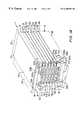
- FIG. 1Ashows a fuel cell assembly 1 in accordance with the principles of the present invention.
- the assembly 1comprises a fuel cell stack 2 having fuel cells arranged in groups of cells identified as groups 11 , 12 , 13 , 14 , 15 , 16 .
- Each of the groups of cells 11 - 16contains a stack of several cells, with a typical number of cells in each group being from 5 to 15 cells.
- the fuel cells in the groups of cells 11 - 16have oxidant gas inlet ports situated on a first face 1 A of the fuel cell stack 1 and have oxidant gas exhaust ports on the opposite face 1 B of the stack. Similarly, the fuel cells in the groups of cells 11 - 16 have fuel inlet ports on another face 1 C of the stack 1 and corresponding fuel exhaust ports on the opposing face 1 D of the stack.
- the fuel cells in the groups of cells 11 - 16are, furthermore, capable of themselves internally reforming hydrocarbon fuel passing through the cells into fuel gas.
- the majority of the fuel gas for the groups of cellsis provided by fuel reformers 21 , 22 , 23 , 24 , 25 , 26 situated in the stack 1 between the groups of cells. These reformers have fuel inlet ports 21 A, 22 A, 23 A, 24 A, 25 A and 26 A on the face 1 C of the stack 1 and reformed fuel outlet ports 21 B, 22 B, 23 B, 24 B, 25 B and 26 B also on the stack face 1 C.
- the fuel assembly 1further comprises manifolds 31 , 32 and 33 .
- the manifolds 32 and 33gas sealingly enclose the faces 1 B and 1 D of the stack 1 and receive the oxidant gas exhaust and fuel gas exhaust, respectively.
- the manifold 31gas sealingly encloses the face 1 C of the stack 1 so that it causes fuel and fuel gas adjacent the face 1 C of the stack to enter the fuel inlet ports of the fuel cells and not escape outward of the stack.
- the fuel cell assembly 1further comprises a top end plate 41 and a bottom end plate 42 .
- the bottom end platesupports a fuel inlet pipe 43 and fuel outlet pipe 44 .
- the fuel cell assemblyfurther includes a reformer fuel delivery system 61 for delivering fuel to the reforming units 21 - 26 .
- the reformer fuel delivery systemis disposed entirely within the sealed, enclosed region between the manifold 31 and the face 1 C of the stack.
- the reformer fuel delivery systemcomprises a fuel supply header 62 which receives fuel from the fuel inlet pipe 43 carried in the end plate 42 .
- the placement of the fuel inlet pipe 43 within the end plate 42is illustrated in greater detail in FIG. 1 B.
- the inlet end 43 a of the pipe 43is adapted to be connected to the fuel feed line (not shown in the figure), while the outlet or exit end 43 b is connected to the fuel supply header 62 located within the manifold 31 .
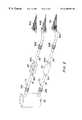
- the header 62delivers the fuel received from the pipe 43 , to feed lines 71 , 72 , 73 , 74 , 75 and 76 , which, in turn, deliver the fuel to the fuel inlet ports 21 A to 26 A of the fuel reformers 21 - 26 .
- the fuel feed lines 71 - 76are of the same construction and each includes a first feed line section 81 connected to the header 62 , a second feed line section 82 connected to a respective fuel inlet port and spaced from the first feed line section 81 and a dielectric insulator 83 .
- the dielectric insulatorbridges the space between the line sections 81 and 82 , thereby connecting the line sections in an electrically isolating manner.
- the first and second feed line sections 81 and 82further include retainer rings 81 A and 82 A, respectively, to prevent movement of the dielectric insulator 83 .
- Bellows 81 B and 82 Bare also provided in the line sections 81 and 82 , respectively, to better accommodate stack shifting without breaking of the lines.
- a fuel mixture containing hydrocarbon fuel and steamis introduced into the fuel pipe 43 in the end plate 42 from the open face 1 A of the stack 1 (where there is no manifold). This fuel is then carried by the pipe 43 to the fuel supply header 62 located within the manifold 31 .
- the feed lines 71 - 76receive the fuel from the supply header 62 and carry it to the individual fuel reformers 21 - 26 .
- the individual feed lines 71 - 76 and fuel supply header 62are all enclosed within the sealed region between the manifold 31 and the stack face 1 C.
- this arrangementeliminates the need for complete gas sealing of the feed lines 71 - 76 , because any possible fuel leak from the lines is contained within the sealed region created by the manifold 31 . Any fuel leaked from the lines will thus be internally reformed in the fuel cells of the fuel cell groups. Since fuel leaks from the feed lines can now be tolerated, the dielectric insulators in the feed lines need not be hermetically sealed to the respective feed line sections, thus reducing the complexity and cost in fabricating the lines.
- each dielectric insulator 83is formed as a simple ceramic tube with an inside diameter matching the outside diameter of the adjoining ends of the feed line sections 81 and 82 .
- the ceramic tube or cylinderis easily slipped over the feed line sections which are preferably formed of metal tubing.
- each ceramic tube 83 on the metal tubes forming the feed line sections 81 and 82is such that at the operating temperature of the fuel cell assembly, the metal tubes exert a radial force on the inner wall of the ceramic tube, closing the gap and sealing the joint. A strong metal to ceramic joint is thus formed and any fuel leakage therethrough will be minimal. Also, any fuel leakage which occurs will be kept within the sealed region defined by the manifold 31 and reformed by the fuel cells of the fuel cell assembly.
- the force exerted on the ceramic tube due to differential thermal expansionis kept below that which would fracture the ceramic.
- each feed lineis also provided with bellows 81 B and 82 B, respectively.
- the bellowsprovide relief for any stress to the line caused by stack height changes during operation of the assembly.
- the fuel mixturei.e., fuel and steam
- the fuel supply header 62can be introduced into the fuel supply header 62 at a much lower temperature (i.e., a temperature in the range of 490° C. to 540° C.) than the normal operating temperature (i.e., a temperature in the range of 540° C. to 650° C.) of the fuel cells of the fuel cell assembly.
- the fuel mixtureis then preheated within the manifold 31 , while flowing through the header and the feed lines. This preheating of the fuel mixture, before entering the fuel reformers, causes it to reach a temperature which is compatible with the operating temperature of the fuel cells of the fuel cell assembly.
- Preheating the fuel mixture in this waybenefits the overall fuel cell system using the fuel cell assembly 1 in two ways: 1) the fuel preheating load in the superheater or the heat recovery steam generator of the fuel cell system is lowered; and 2) the fuel cell cooling load is lowered by an equal amount.
- the heating load of the fuel streamcan be lowered by >100° C. and the fuel cell cooling load can be lowered by ⁇ 20° C. by preheating the fuel mixture inside the manifold 31 as in the present invention.
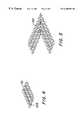
- FIG. 3A detailed view of the fuel reformer 21 is shown in FIG. 3 .
- the reformers 22 - 26are of similar construction.
- catalyst pellets 105are strategically placed in the corrugations of the plate 101 . This placement optimizes the endothermic reforming reaction profile in order to minimize the thermal gradient within the fuel cell stack.
- the plate 101is fitted with a baffle 102 to direct flow within the reformer 21 as shown by the arrows 104 , i.e., so that the fuel entering the inlet port 21 A undergoes a U-type flow path through the plate 101 , and is directed to the outlet port 21 B.
- the loading of the catalyst 105 and the arrangement of the baffle 102 in the reformer 21are such that the reforming reaction profile within the reformer matches the fuel cell heat production profile.
- the fuel mixtureis introduced with a high velocity at the inlet port 21 A of the reformer and the kinetic energy in the fuel mixture stream provides the necessary energy to turn the flow around in the U-type path.
- the reformed gasthus exits at the exit port 21 B, which is on the same side of the reformer as the inlet port 21 A.
- the fuel inlet port 21 A of the reformer 21is rectangular.
- Each feed line section 82is provided with a fan-like transition duct 84 which connects the rectangular inlet port 21 A with the end of the round tube forming the feed line section 82 .
- the corrugated plate 101 of the reformer 21is wrapped in a thin metallic foil 103 A (e.g., a nickel foil of two to four mils. thickness) covered by a cover member 103 B (e.g., nickel or nickel clad stainless steel material of 2 to 12 mils. thickness) to form a reformer structure.
- a thin metallic foil 103 Ae.g., a nickel foil of two to four mils. thickness
- a cover member 103 Be.g., nickel or nickel clad stainless steel material of 2 to 12 mils. thickness
- the reformer 21is in partially disassembled form in which the foil member 103 A and cover member 103 B are separated from each other.
- the foil member 103 Ahas a central region 201 having sides 201 A, 201 B, 201 C and 201 D.
- Three flap regions 201 E, 201 F and 201 Gextend from the sides 201 A through 201 C, respectively.
- the flap regions 201 E, 201 F and 201 Gare trapezoidal in shape.
- each of the flap regions of 201 E and 201 Ghas a rectangular shape at its open side.
- the corrugated plate 101 and baffle 102are situated on the central region 201 of the foil member 103 A.
- the flap regions 201 E, 201 F, 201 Gare then folded over as indicated by the arrows 301 - 303 so that they face the central region 201 and abut the sides of corrugated plate 101 .
- the cover member 103 Bis then laid over the central region 201 and the flap regions 201 E, 201 F and 201 G contacting these regions and the baffle 102 . Due to compression, the two flap regions 201 E and 201 G then become sealed to the flap region 201 F and the cover member 103 B becomes sealed to the three flap regions 201 E, 201 F, 201 G to form the reformer.
- the space between the central region 201 of the foil member 103 A and the cover member 103 Bdefines the open side 201 D of the reformer.
Landscapes
- Life Sciences & Earth Sciences (AREA)
- Engineering & Computer Science (AREA)
- Manufacturing & Machinery (AREA)
- Sustainable Development (AREA)
- Sustainable Energy (AREA)
- Chemical & Material Sciences (AREA)
- Chemical Kinetics & Catalysis (AREA)
- Electrochemistry (AREA)
- General Chemical & Material Sciences (AREA)
- Hydrogen, Water And Hydrids (AREA)
- Fuel Cell (AREA)
Abstract
Description
Claims (33)
Priority Applications (6)
| Application Number | Priority Date | Filing Date | Title |
|---|---|---|---|
| US09/251,196US6200696B1 (en) | 1999-02-16 | 1999-02-16 | Internal reforming fuel cell assembly with simplified fuel feed |
| PCT/US1999/030544WO2000049672A1 (en) | 1999-02-16 | 1999-12-20 | Internal reforming fuel cell assembly with simplified fuel feed |
| HK02107063.5AHK1045763B (en) | 1999-02-16 | 1999-12-20 | Fuel cell assembly and method for use with the fuel cell assembly |
| EP99968521AEP1157437B1 (en) | 1999-02-16 | 1999-12-20 | Internal reforming fuel cell assembly with simplified fuel feed |
| DE69910624TDE69910624T2 (en) | 1999-02-16 | 1999-12-20 | FUEL CELL CONSTRUCTION WITH INTERNAL REFORMATION AND SIMPLIFIED FUEL FEEDING |
| CNB998159999ACN1172395C (en) | 1999-02-16 | 1999-12-20 | Fuel cell assembly and method for use with a fuel cell assembly |
Applications Claiming Priority (1)
| Application Number | Priority Date | Filing Date | Title |
|---|---|---|---|
| US09/251,196US6200696B1 (en) | 1999-02-16 | 1999-02-16 | Internal reforming fuel cell assembly with simplified fuel feed |
Publications (1)
| Publication Number | Publication Date |
|---|---|
| US6200696B1true US6200696B1 (en) | 2001-03-13 |
Family
ID=22950898
Family Applications (1)
| Application Number | Title | Priority Date | Filing Date |
|---|---|---|---|
| US09/251,196Expired - LifetimeUS6200696B1 (en) | 1999-02-16 | 1999-02-16 | Internal reforming fuel cell assembly with simplified fuel feed |
Country Status (6)
| Country | Link |
|---|---|
| US (1) | US6200696B1 (en) |
| EP (1) | EP1157437B1 (en) |
| CN (1) | CN1172395C (en) |
| DE (1) | DE69910624T2 (en) |
| HK (1) | HK1045763B (en) |
| WO (1) | WO2000049672A1 (en) |
Cited By (21)
| Publication number | Priority date | Publication date | Assignee | Title |
|---|---|---|---|---|
| US20020168566A1 (en)* | 2001-05-01 | 2002-11-14 | Yazaki Corporation | Battery connecting portion-protecting cover |
| US20040023085A1 (en)* | 2002-08-05 | 2004-02-05 | Lightner Gene E. | Prodoction of electricity from fuel cells depending on gasification of carbonatious compounds |
| US20040071617A1 (en)* | 2002-10-11 | 2004-04-15 | Scott Blanchet | Fuel reformer |
| US20040072039A1 (en)* | 2002-07-01 | 2004-04-15 | The Regents Of The University Of California | MEMS-based fuel cells with integrated catalytic fuel processor and method thereof |
| US6740444B2 (en) | 2001-10-29 | 2004-05-25 | Hewlett-Packard Development Company, L.P. | PEM fuel cell with alternating ribbed anodes and cathodes |
| US6830736B1 (en)* | 1999-09-15 | 2004-12-14 | Ballard Power Systems Ag | Apparatus for carrying out a heterogeneously catalyzed reaction |
| US20060123705A1 (en)* | 2004-12-09 | 2006-06-15 | Zhiwen Ma | High performance internal reforming unit for high temperature fuel cells |
| US20070184310A1 (en)* | 2006-02-07 | 2007-08-09 | Doosan Heavy Industries & Construction Co., Ltd. | Molten Carbonate Fuel Cell Provided with Indirect Internal Steam Reformer |
| US20070190373A1 (en)* | 2006-02-10 | 2007-08-16 | Doosan Heavy Industries & Construction Co., Ltd. | Separator plate having fuel reforming chamber for mcfc and manufacturing method thereof |
| US20080160365A1 (en)* | 2006-12-29 | 2008-07-03 | Doosan Heavy Industries & Construction Co., Ltd. | Separator for molten carbonate fuel cell |
| US20090136813A1 (en)* | 2005-11-02 | 2009-05-28 | Katsuya Hirata | Fuel Cell |
| WO2009149314A2 (en) | 2008-06-06 | 2009-12-10 | Fuelcell Energy, Inc. | Modular fuel cell stack assembly including anode gas oxidizer and integrated external manifolds for use in fuel cell stack modules |
| US20100047641A1 (en)* | 2008-08-19 | 2010-02-25 | Jahnke Fred C | High-efficiency dual-stack molten carbonate fuel cell system |
| KR100953932B1 (en) | 2009-12-08 | 2010-04-22 | (주)보림 | Inner reforming type separator for molten carbonate fuel cell and manufacturing method thereof |
| US20100227234A1 (en)* | 2009-03-09 | 2010-09-09 | Zhiwen Ma | Internally reforming fuel cell assembly with staged fuel flow and selective catalyst loading for improved temperature uniformity and efficiency |
| DE102011100621A1 (en) | 2011-05-05 | 2012-11-08 | Mtu Onsite Energy Gmbh | Fuel cell assembly has reforming unit comprising anode inlet-side fuel inlet provided for supplying fuel from hollow frame of anode inlet gas cap to fluid outlets |
| KR101244507B1 (en) | 2011-08-02 | 2013-03-18 | 포스코에너지 주식회사 | Indirect internal reformer for solid oxide fuel cell |
| KR101294469B1 (en) | 2011-11-02 | 2013-08-07 | 포스코에너지 주식회사 | Indirect internal reformer for solid oxide fuel cell |
| US20140356752A1 (en)* | 2007-05-10 | 2014-12-04 | Fuelcell Energy, Inc. | Fuel cell assembly and method of making same |
| JP2017212041A (en)* | 2016-05-23 | 2017-11-30 | 京セラ株式会社 | Cell stack device, fuel battery module and fuel battery device |
| WO2018049212A1 (en) | 2016-09-09 | 2018-03-15 | Fuelcell Energy, Inc. | Molten carbonate fuel cell stack having direct and indirect internal reformers |
Families Citing this family (8)
| Publication number | Priority date | Publication date | Assignee | Title |
|---|---|---|---|---|
| US7277765B1 (en) | 2000-10-12 | 2007-10-02 | Bose Corporation | Interactive sound reproducing |
| JP4424863B2 (en)* | 2001-02-23 | 2010-03-03 | 三洋電機株式会社 | Fuel cell |
| US7387650B2 (en)* | 2002-05-02 | 2008-06-17 | Mitsubishi Heavy Industries, Ltd. | Fuel cell power generation system and method for operating the same |
| KR100551060B1 (en)* | 2004-06-29 | 2006-02-09 | 삼성에스디아이 주식회사 | Fuel Cell System, Reformer Used In It And Method Of Manufacturing The Same |
| DE102007051514A1 (en) | 2007-10-29 | 2009-04-30 | Mtu Onsite Energy Gmbh | A fuel cell assembly |
| DK178843B1 (en)* | 2014-07-16 | 2017-03-20 | Serenergy As | A reformer for a fuel cell system |
| CN106892402A (en)* | 2015-12-18 | 2017-06-27 | 中国科学院大连化学物理研究所 | A kind of corrugated plate dst microchannel methanol steam reformation hydrogen production reactor |
| DE102023209986A1 (en)* | 2023-10-12 | 2025-04-17 | Siemens Energy Global GmbH & Co. KG | Fuel cell device with insulating ceramic components |
Citations (10)
| Publication number | Priority date | Publication date | Assignee | Title |
|---|---|---|---|---|
| US3488226A (en) | 1965-11-08 | 1970-01-06 | Inst Gas Technology | Process for generation of hydrogen from hydrocarbons and use thereof in molten carbonate fuel cells |
| US4647516A (en)* | 1985-02-20 | 1987-03-03 | Mitsubishi Denki Kabushiki Kaisha | Internal reforming type fuel cell |
| US4788110A (en)* | 1987-10-20 | 1988-11-29 | Energy Research Corporation | Fuel cell with partially shielded internal reformer |
| US4873155A (en) | 1987-11-10 | 1989-10-10 | Fuji Electric Co., Ltd. | Fuel cell manifolds |
| US4877693A (en) | 1985-12-23 | 1989-10-31 | Energy Research Corporation | Fuel cell apparatus for internal reforming |
| US4983470A (en)* | 1987-08-28 | 1991-01-08 | Mitsubishi Denki Kabushiki Kaisha | Protective material for molten carbonate fuel cell |
| US5175062A (en) | 1991-01-30 | 1992-12-29 | Energy Research Corporation | Reforming unit for fuel cell stack |
| US5426002A (en)* | 1992-09-11 | 1995-06-20 | Mitsubishi Denki Kabushiki Kaisha | Internal reforming type fuel cell apparatus and operation method of same |
| US5470670A (en)* | 1993-03-01 | 1995-11-28 | Matsushita Electric Industrial Co., Ltd. | Fuel cell |
| US5660941A (en)* | 1996-06-19 | 1997-08-26 | Energy Research Corporation | Catalyst assembly for internal reforming fuel cell |
Family Cites Families (3)
| Publication number | Priority date | Publication date | Assignee | Title |
|---|---|---|---|---|
| US5348814A (en)* | 1992-03-11 | 1994-09-20 | Matsushita Electric Industrial Co., Ltd. | Internal reforming type molten carbonate fuel cell |
| US5733347A (en)* | 1995-12-27 | 1998-03-31 | International Fuel Cells Corp. | Compact fuel gas reformer assemblage |
| US5858314A (en)* | 1996-04-12 | 1999-01-12 | Ztek Corporation | Thermally enhanced compact reformer |
- 1999
- 1999-02-16USUS09/251,196patent/US6200696B1/ennot_activeExpired - Lifetime
- 1999-12-20WOPCT/US1999/030544patent/WO2000049672A1/ennot_activeCeased
- 1999-12-20CNCNB998159999Apatent/CN1172395C/ennot_activeExpired - Fee Related
- 1999-12-20EPEP99968521Apatent/EP1157437B1/ennot_activeExpired - Lifetime
- 1999-12-20DEDE69910624Tpatent/DE69910624T2/ennot_activeExpired - Lifetime
- 1999-12-20HKHK02107063.5Apatent/HK1045763B/ennot_activeIP Right Cessation
Patent Citations (10)
| Publication number | Priority date | Publication date | Assignee | Title |
|---|---|---|---|---|
| US3488226A (en) | 1965-11-08 | 1970-01-06 | Inst Gas Technology | Process for generation of hydrogen from hydrocarbons and use thereof in molten carbonate fuel cells |
| US4647516A (en)* | 1985-02-20 | 1987-03-03 | Mitsubishi Denki Kabushiki Kaisha | Internal reforming type fuel cell |
| US4877693A (en) | 1985-12-23 | 1989-10-31 | Energy Research Corporation | Fuel cell apparatus for internal reforming |
| US4983470A (en)* | 1987-08-28 | 1991-01-08 | Mitsubishi Denki Kabushiki Kaisha | Protective material for molten carbonate fuel cell |
| US4788110A (en)* | 1987-10-20 | 1988-11-29 | Energy Research Corporation | Fuel cell with partially shielded internal reformer |
| US4873155A (en) | 1987-11-10 | 1989-10-10 | Fuji Electric Co., Ltd. | Fuel cell manifolds |
| US5175062A (en) | 1991-01-30 | 1992-12-29 | Energy Research Corporation | Reforming unit for fuel cell stack |
| US5426002A (en)* | 1992-09-11 | 1995-06-20 | Mitsubishi Denki Kabushiki Kaisha | Internal reforming type fuel cell apparatus and operation method of same |
| US5470670A (en)* | 1993-03-01 | 1995-11-28 | Matsushita Electric Industrial Co., Ltd. | Fuel cell |
| US5660941A (en)* | 1996-06-19 | 1997-08-26 | Energy Research Corporation | Catalyst assembly for internal reforming fuel cell |
Cited By (35)
| Publication number | Priority date | Publication date | Assignee | Title |
|---|---|---|---|---|
| US6830736B1 (en)* | 1999-09-15 | 2004-12-14 | Ballard Power Systems Ag | Apparatus for carrying out a heterogeneously catalyzed reaction |
| US20020168566A1 (en)* | 2001-05-01 | 2002-11-14 | Yazaki Corporation | Battery connecting portion-protecting cover |
| US6740444B2 (en) | 2001-10-29 | 2004-05-25 | Hewlett-Packard Development Company, L.P. | PEM fuel cell with alternating ribbed anodes and cathodes |
| US20040072039A1 (en)* | 2002-07-01 | 2004-04-15 | The Regents Of The University Of California | MEMS-based fuel cells with integrated catalytic fuel processor and method thereof |
| US7993785B2 (en) | 2002-07-01 | 2011-08-09 | Lawrence Livermore National Security, Llc | MEMS-based fuel cells with integrated catalytic fuel processor and method thereof |
| US20040023085A1 (en)* | 2002-08-05 | 2004-02-05 | Lightner Gene E. | Prodoction of electricity from fuel cells depending on gasification of carbonatious compounds |
| US20040071617A1 (en)* | 2002-10-11 | 2004-04-15 | Scott Blanchet | Fuel reformer |
| US7431746B2 (en) | 2004-12-09 | 2008-10-07 | Fuelcell Energy, Inc. | High performance internal reforming unit for high temperature fuel cells |
| US20060123705A1 (en)* | 2004-12-09 | 2006-06-15 | Zhiwen Ma | High performance internal reforming unit for high temperature fuel cells |
| WO2006062625A3 (en)* | 2004-12-09 | 2007-05-03 | Fuelcell Energy Inc | High performance internal reforming unit for high temperature fuel cells |
| KR101455388B1 (en)* | 2004-12-09 | 2014-10-27 | 퓨얼 셀 에너지, 인크 | High performance internal reforming unit for high temperature fuel cells |
| JP2008522942A (en)* | 2004-12-09 | 2008-07-03 | フュエルセル エナジー, インコーポレイテッド | High-performance internal reformer for high-temperature fuel cells |
| US8034496B2 (en)* | 2005-11-02 | 2011-10-11 | Mitsubishi Materials Corporation | Fuel cell |
| US20090136813A1 (en)* | 2005-11-02 | 2009-05-28 | Katsuya Hirata | Fuel Cell |
| US20070184310A1 (en)* | 2006-02-07 | 2007-08-09 | Doosan Heavy Industries & Construction Co., Ltd. | Molten Carbonate Fuel Cell Provided with Indirect Internal Steam Reformer |
| US20070190373A1 (en)* | 2006-02-10 | 2007-08-16 | Doosan Heavy Industries & Construction Co., Ltd. | Separator plate having fuel reforming chamber for mcfc and manufacturing method thereof |
| US8753784B2 (en) | 2006-12-29 | 2014-06-17 | Doosan Heavy Industries & Construction Co., Ltd. | Separator for molten carbonate fuel cell |
| US20080160365A1 (en)* | 2006-12-29 | 2008-07-03 | Doosan Heavy Industries & Construction Co., Ltd. | Separator for molten carbonate fuel cell |
| US20140356752A1 (en)* | 2007-05-10 | 2014-12-04 | Fuelcell Energy, Inc. | Fuel cell assembly and method of making same |
| US9548510B2 (en)* | 2007-05-10 | 2017-01-17 | Fuelcell Energy, Inc. | Method of making fuel cell component using adhesive tape to maintain positioning of loading material particles |
| US8962210B2 (en) | 2008-06-06 | 2015-02-24 | Fuelcell Energy, Inc. | Modular fuel cell stack assembly including anode gas oxidizer and integrated external manifolds for use in fuel cell stack modules |
| US20110081592A1 (en)* | 2008-06-06 | 2011-04-07 | Zhiwen Ma | Modular fuel cell stack assembly including anode gas oxidizer and integrated external manifolds for use in fuel cell stack modules |
| WO2009149314A2 (en) | 2008-06-06 | 2009-12-10 | Fuelcell Energy, Inc. | Modular fuel cell stack assembly including anode gas oxidizer and integrated external manifolds for use in fuel cell stack modules |
| US8062799B2 (en) | 2008-08-19 | 2011-11-22 | Fuelcell Energy, Inc. | High-efficiency dual-stack molten carbonate fuel cell system |
| US8236458B2 (en) | 2008-08-19 | 2012-08-07 | Fuelcell Energy, Inc. | High-efficiency dual-stack molten carbonate fuel cell system |
| US20100047641A1 (en)* | 2008-08-19 | 2010-02-25 | Jahnke Fred C | High-efficiency dual-stack molten carbonate fuel cell system |
| WO2010104845A2 (en) | 2009-03-09 | 2010-09-16 | Fuelcell Energy, Inc. | Internally reforming fuel cell assembly with staged fuel flow and selective catalyst loading for improved temperature uniformity and efficiency |
| US20100227234A1 (en)* | 2009-03-09 | 2010-09-09 | Zhiwen Ma | Internally reforming fuel cell assembly with staged fuel flow and selective catalyst loading for improved temperature uniformity and efficiency |
| US8822090B2 (en)* | 2009-03-09 | 2014-09-02 | Fuelcell Energy, Inc. | Internally reforming fuel cell assembly with staged fuel flow and selective catalyst loading for improved temperature uniformity and efficiency |
| KR100953932B1 (en) | 2009-12-08 | 2010-04-22 | (주)보림 | Inner reforming type separator for molten carbonate fuel cell and manufacturing method thereof |
| DE102011100621A1 (en) | 2011-05-05 | 2012-11-08 | Mtu Onsite Energy Gmbh | Fuel cell assembly has reforming unit comprising anode inlet-side fuel inlet provided for supplying fuel from hollow frame of anode inlet gas cap to fluid outlets |
| KR101244507B1 (en) | 2011-08-02 | 2013-03-18 | 포스코에너지 주식회사 | Indirect internal reformer for solid oxide fuel cell |
| KR101294469B1 (en) | 2011-11-02 | 2013-08-07 | 포스코에너지 주식회사 | Indirect internal reformer for solid oxide fuel cell |
| JP2017212041A (en)* | 2016-05-23 | 2017-11-30 | 京セラ株式会社 | Cell stack device, fuel battery module and fuel battery device |
| WO2018049212A1 (en) | 2016-09-09 | 2018-03-15 | Fuelcell Energy, Inc. | Molten carbonate fuel cell stack having direct and indirect internal reformers |
Also Published As
| Publication number | Publication date |
|---|---|
| CN1172395C (en) | 2004-10-20 |
| DE69910624T2 (en) | 2004-06-17 |
| EP1157437A4 (en) | 2002-04-17 |
| EP1157437A1 (en) | 2001-11-28 |
| DE69910624D1 (en) | 2003-09-25 |
| HK1045763B (en) | 2005-04-01 |
| HK1045763A1 (en) | 2002-12-06 |
| EP1157437B1 (en) | 2003-08-20 |
| CN1348617A (en) | 2002-05-08 |
| WO2000049672A1 (en) | 2000-08-24 |
Similar Documents
| Publication | Publication Date | Title |
|---|---|---|
| US6200696B1 (en) | Internal reforming fuel cell assembly with simplified fuel feed | |
| US7659022B2 (en) | Integrated solid oxide fuel cell and fuel processor | |
| US8241801B2 (en) | Integrated solid oxide fuel cell and fuel processor | |
| US20070196704A1 (en) | Intergrated solid oxide fuel cell and fuel processor | |
| US5811065A (en) | Burner exhaust gas collection assembly for a catalytic reformer | |
| US5366819A (en) | Thermally integrated reformer for solid oxide fuel cells | |
| US9799902B2 (en) | Pre-reformer for selective reformation of higher hydrocarbons | |
| JPH0316752B2 (en) | ||
| US20100062298A1 (en) | Fuel cell and method of operating the same | |
| US20080171257A1 (en) | Modular fuel-cell stack assembly | |
| EP2973828B1 (en) | Solid oxide fuel cell bundle assembly with insulation end pieces and tilt pad tie down clamp | |
| EP2220709B1 (en) | Fuel cell assembly | |
| JPH09259910A (en) | Molten carbonate fuel cell and power generator using the same | |
| CN115692756A (en) | Compact high temperature electrochemical cell stack architecture | |
| WO2014081651A1 (en) | A fuel cell system hot box insulation | |
| US7008715B2 (en) | Thermal and vibrational break for high-temperature gas tubes in a solid-oxide fuel cell | |
| US7524572B2 (en) | Fuel cell system with thermally integrated combustor and corrugated foil reformer | |
| JP2001342002A (en) | Fuel reformer | |
| US20100190083A1 (en) | Solid oxide fuel cell unit for use in distributed power generation | |
| JPH03283360A (en) | Power generating device |
Legal Events
| Date | Code | Title | Description |
|---|---|---|---|
| AS | Assignment | Owner name:ENERGY RESEARCH CORPORATION, CONNECTICUT Free format text:ASSIGNMENT OF ASSIGNORS INTEREST;ASSIGNORS:FAROOQUE, MOHAMMAD;NOVACCO, LAWRENCE J.;ALLEN, JEFFREY P.;REEL/FRAME:009774/0554;SIGNING DATES FROM 19990129 TO 19990202 | |
| STCF | Information on status: patent grant | Free format text:PATENTED CASE | |
| CC | Certificate of correction | ||
| FEPP | Fee payment procedure | Free format text:PAYOR NUMBER ASSIGNED (ORIGINAL EVENT CODE: ASPN); ENTITY STATUS OF PATENT OWNER: LARGE ENTITY | |
| FPAY | Fee payment | Year of fee payment:4 | |
| AS | Assignment | Owner name:ENERGY, UNITED STATES DEPARTMENT OF, DISTRICT OF C Free format text:CONFIRMATORY LICENSE;ASSIGNOR:FUEL CELL ENERGY, INC.;REEL/FRAME:017724/0078 Effective date:20050811 | |
| FPAY | Fee payment | Year of fee payment:8 | |
| FEPP | Fee payment procedure | Free format text:PAT HOLDER NO LONGER CLAIMS SMALL ENTITY STATUS, ENTITY STATUS SET TO UNDISCOUNTED (ORIGINAL EVENT CODE: STOL); ENTITY STATUS OF PATENT OWNER: LARGE ENTITY | |
| FPAY | Fee payment | Year of fee payment:12 | |
| AS | Assignment | Owner name:POSCO ENERGY CO., LTD., KOREA, REPUBLIC OF Free format text:NOTICE OF LICENSE;ASSIGNOR:FUELCELL ENERGY, INC.;REEL/FRAME:029731/0562 Effective date:20121031 | |
| AS | Assignment | Owner name:FUELCELL ENERGY, INC., CONNECTICUT Free format text:CHANGE OF NAME;ASSIGNOR:ENERGY RESEARCH CORPORATION;REEL/FRAME:038094/0551 Effective date:19990917 |