US6200319B1 - Surgical trephine - Google Patents
Surgical trephineDownload PDFInfo
- Publication number
- US6200319B1 US6200319B1US09/416,913US41691399AUS6200319B1US 6200319 B1US6200319 B1US 6200319B1US 41691399 AUS41691399 AUS 41691399AUS 6200319 B1US6200319 B1US 6200319B1
- Authority
- US
- United States
- Prior art keywords
- piston
- bore
- trephine
- surgical
- stop
- Prior art date
- Legal status (The legal status is an assumption and is not a legal conclusion. Google has not performed a legal analysis and makes no representation as to the accuracy of the status listed.)
- Expired - Fee Related
Links
Images


Classifications
- A—HUMAN NECESSITIES
- A61—MEDICAL OR VETERINARY SCIENCE; HYGIENE
- A61B—DIAGNOSIS; SURGERY; IDENTIFICATION
- A61B17/00—Surgical instruments, devices or methods
- A61B17/16—Instruments for performing osteoclasis; Drills or chisels for bones; Trepans
- A61B17/1637—Hollow drills or saws producing a curved cut, e.g. cylindrical
Definitions
- This inventionrelates to a surgical trephine adapted for boring an opening in tamped bone chips.
- the present inventionis intended to provide an instrument which can be used for cutting the required cavity into the bone chips in operations of the kind described above, although it can be used for any cavity in which bone chips are used and a substantially parallel cavity is required.
- a surgical trephine adapted for boring an opening in tamped bone chipsincludes a hollow elongate body portion having an internal bore and the distal end of which has an annular cutting rim, a piston located in the bore with a piston surface facing towards said cutting rim and means for moving the piston in the bore.
- an elongate cavitycan be cut in the bone chip, with the debris from the cutting entering the distal end of the internal bore and slowly pushing the piston up the bore away from the distal end.
- the chipscan then be easily dislodged from the bore by displacing the piston.
- the body portionmay include an aperture in the wall passing into the bore at a point spaced away from the distal end of the instrument to facilitate cleaning after operation.
- the action of the instrument when used by the surgeoncan be back and forth or with a continuous rotation or with an up and down motion in the form of a pile driver.
- an extension or extended portion of the pistonprojects beyond the proximal end of the body portion and a stop can be provided for limiting the movement of the piston up said bore and away from the distal end to a position adjacent the proximal end of the aperture.
- the annular cutting rimis provided with cutting teeth although, in certain circumstances, merely a sharpened edge may be required.
- the proximal end of the extended portion of the piston or an extension thereofcan be provided with a removable stop to limit the movement of the piston in a distal direction. This stop can be removed so that the device can be completely dismantled for cleaning but when it is in position it locates the piston in the bore and prevents the piston dropping through the main body.
- the hollow elongate body portionis provided with an operating handle which can be in the form of a T-piece.
- the hollow elongate body portioncan also be provided with a depth gauge and means such as a reference mark can be provided on the extended portion of the piston, or extension thereof, to provide a position indicator.
- the proximal end of the extended portion of the piston, or an extension thereof,can be provided with a coupling for attaching a power source so that the device can be operated by a power device.
- the pistoncan be provided with a cannulation to accept a guide wire so that the trephine can be used as one of a series of operations when carrying out the preparation of the bone for implantation.
- FIG. 1is a diagrammatic illustration of a typical phantom or trial for a prosthesis with a long stem impacted into bone chips in a femur;
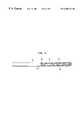
- FIG. 2is a side elevation of a surgical trephine according to the present invention.
- FIG. 3is a cross-sectional front elevation of the device shown in FIG. 2 on the lines III—III;
- FIG. 4is an isometric view of the trephine according to the invention.
- FIG. 5is an enlarged view of the teeth used on the annular cutting rim of the device according to the invention.
- FIG. 6is a cross-sectional view of the distal end of the trephine showing the piston in the trephine bore.
- FIG. 1a femur 1 is shown in which the intramedullary canal has been treated to provide a cavity 2 into which a prosthesis with a long stem is intended to be inserted.
- a phantom or trial prosthesis 3 with a long stem 4is shown which will eventually be removed and replaced by the surgical prosthesis.
- This techniqueis described and shown in U.S. Pat. No. 5,788,704, the teachings of which are incorporated herein by reference.
- the cavity 2has been prepared it is filled with bone chips 5 and these are tamped and compressed.
- the present inventionallows the distal end of the cavity to be completely filled with bone chips up to a level indicated by reference numeral 6 .
- a guide wire 7is placed in position, usually held by a retaining plug 8 , and this guide wire is used, in well known manner, to guide and accurately locate the various components which are used during the operation.
- the guide wireis, of course, placed in position before the bone chips are inserted.
- a phantom techniqueis employed the phantom 3 is withdrawn, the cavity within the bone chips is lined with cement and the surgical prosthesis subsequently inserted with or without the use of a guide wire.
- the present inventionprovides a trephine which can be used to cut out the tamped and compressed bone fragments beneath the level 6 and comprises a hollow elongate body portion which has an internal bore 11 and the distal end 12 of which has an annular cutting rim 13 .
- the cutting rimcan be provided with teeth 14 , as shown in FIG. 5 .
- an elongate piston 14 ′Located in the bore 11 is an elongate piston 14 ′ which has an extension 15 which projects from the proximal end 16 of the main body 10 .
- the main body 10is extended by a t-shaped cross-piece 17 which acts an operating handle.
- the proximal end of the extension 15is provided with a knurled nut 18 which is shaped to allow easy removal and is adapted to receive an appropriate operating attachment from a power tool. As the nut 18 is screw threaded onto the end of the extension 15 it can be readily removed by hand but it acts as a stop to prevent the piston 14 ′ passing completely through the main body portion 10 .
- the distal end of the piston 14 ′is enlarged at 19 and the diameter of the bore 11 is also enlarged at its distal end 11 to accommodate the enlarged portion 19 on the piston.
- An aperture 20is provided in the wall of the bore 11 and the enlarged portion of the bore ends at the proximal end of this aperture.
- the piston 14 ′can move towards the distal end of the bore 11 until it emerges from the distal end thereof. Further movement is however restricted by the stop 18 .
- the pistonIn the other proximal direction the piston can move up the bore 11 until it reaches the position shown in the drawings and where the enlarged part of the piston 19 meets the thicker wall 11 a of the upper part of the bore 11 .
- the outer surface of the elongate body portionis provided with a depth gauge in the form of appropriate markings indicated by reference numeral 25 and the piston extension 15 carries a position indicator 26 which indicates when the piston 19 has reached the upper end of the aperture 20 .
- the piston 14 and extension 15are provided with means to accept a guide wire in the form of a guide bore 27 .
- the trephineis fed down a guide wire, for example similar to that shown in FIG. 1 and indicated by reference numeral 7 , and a backwards and forwards or rotary movement is applied by the operating handle 17 to cause the cutting rim 13 to cut into the bone chips, the chips which have been cut away passing up the bore 11 and pushing the face 28 of the piston in front of them.
- the precise depth of the trephine within the bonecan be seen from the depth gauge 25 . Frequent removal of the device will enable the surgeon to see how far the bone chips have passed up the bore 11 but the position indicator 26 will immediately make him aware if the lower end of the bore 11 has become completely filled.
- the deviceis now removed from the cavity and the bone chips can be easily expelled by pushing the piston downwardly so that the chips are expelled through the opening 20 or through the open distal end. Cutting can now be resumed until the required depth, as indicated on the depth gauge 25 , is achieved to thus provide an opening which is suitable to receive the prosthesis, or phantom prosthesis, which is to be inserted.
- the outer diameter of the elongate body portionwill be appropriate for the prosthesis with which it is to be used.
- the constructionis such that the trephine can be easily dismantled for cleaning. Thus, it is merely necessary to remove the stop 18 so that the piston can slide out of the bore 11 .
- the operating handle 17is screw threaded onto the proximal end of the body portion 10 so that it can also be easily removed.
- the constructioncan be such that a number of body portions of different external diameters can be provided but with a bore of a single diameter so that the piston can be used with other body portions, as can the handle 17 .
- a series of devicescan be provided for different diameters.
- One of the advantages of the pistonis that it can be used to clean the bore 11 during use and because of the stops it reduces the possibility of jamming bone chips in the bore 11 if a surgeon continues to operate the device with the bore full.
Landscapes
- Health & Medical Sciences (AREA)
- Surgery (AREA)
- Life Sciences & Earth Sciences (AREA)
- Biomedical Technology (AREA)
- Medical Informatics (AREA)
- Orthopedic Medicine & Surgery (AREA)
- Oral & Maxillofacial Surgery (AREA)
- Engineering & Computer Science (AREA)
- Dentistry (AREA)
- Heart & Thoracic Surgery (AREA)
- Nuclear Medicine, Radiotherapy & Molecular Imaging (AREA)
- Molecular Biology (AREA)
- Animal Behavior & Ethology (AREA)
- General Health & Medical Sciences (AREA)
- Public Health (AREA)
- Veterinary Medicine (AREA)
- Surgical Instruments (AREA)
- Prostheses (AREA)
Abstract
Description
1. Field of the Invention
This invention relates to a surgical trephine adapted for boring an opening in tamped bone chips.
2. Description of the Prior Art
Modern surgical techniques, especially as applied to hip prostheses, sometimes require a prosthetic device with an elongated stem. These devices are used when not only are there problems with the hip joint but where there is also the possibility of fracturing in the length of the femur. The addition of a standard length prosthesis stem into such a femur can sometimes create further problems and for this reason a stem of much longer length is employed. The distal portion of such stems is usually parallel because of the extended length and the narrowing of the femur and its intramedullary canal.
In modern techniques bone chips can be employed to line the intramedullary canal and these chips are first tamped into position, for example as described and shown in the Applicants U.S. Pat. No. 5,788,704. This patent shows a method and apparatus for implanting a prosthesis in which a bone cavity is filled with bone chips which are compressed.
When such a technique is used for long prosthesis stems there are difficulties in shaping the distal end of the cavity due, not only to the long length, but also to the possibilities of causing further compression of the bone chips and thus tending to expand the filling and create fractures in the bone structure.
The present invention is intended to provide an instrument which can be used for cutting the required cavity into the bone chips in operations of the kind described above, although it can be used for any cavity in which bone chips are used and a substantially parallel cavity is required.
According to the present invention a surgical trephine adapted for boring an opening in tamped bone chips includes a hollow elongate body portion having an internal bore and the distal end of which has an annular cutting rim, a piston located in the bore with a piston surface facing towards said cutting rim and means for moving the piston in the bore.
With this device an elongate cavity can be cut in the bone chip, with the debris from the cutting entering the distal end of the internal bore and slowly pushing the piston up the bore away from the distal end. When the body portion is withdrawn from the cavity, the chips can then be easily dislodged from the bore by displacing the piston.
The body portion may include an aperture in the wall passing into the bore at a point spaced away from the distal end of the instrument to facilitate cleaning after operation. The action of the instrument when used by the surgeon can be back and forth or with a continuous rotation or with an up and down motion in the form of a pile driver.
Preferably an extension or extended portion of the piston projects beyond the proximal end of the body portion and a stop can be provided for limiting the movement of the piston up said bore and away from the distal end to a position adjacent the proximal end of the aperture.
Preferably the annular cutting rim is provided with cutting teeth although, in certain circumstances, merely a sharpened edge may be required.
The proximal end of the extended portion of the piston or an extension thereof can be provided with a removable stop to limit the movement of the piston in a distal direction. This stop can be removed so that the device can be completely dismantled for cleaning but when it is in position it locates the piston in the bore and prevents the piston dropping through the main body.
Preferably the hollow elongate body portion is provided with an operating handle which can be in the form of a T-piece.
The hollow elongate body portion can also be provided with a depth gauge and means such as a reference mark can be provided on the extended portion of the piston, or extension thereof, to provide a position indicator.
If desired the proximal end of the extended portion of the piston, or an extension thereof, can be provided with a coupling for attaching a power source so that the device can be operated by a power device.
The piston can be provided with a cannulation to accept a guide wire so that the trephine can be used as one of a series of operations when carrying out the preparation of the bone for implantation.
The invention can be performed in various ways but one embodiment will now be described by way of example and with reference to the accompanying drawings, in which:
FIG. 1 is a diagrammatic illustration of a typical phantom or trial for a prosthesis with a long stem impacted into bone chips in a femur;
FIG. 2 is a side elevation of a surgical trephine according to the present invention;
FIG. 3 is a cross-sectional front elevation of the device shown in FIG. 2 on the lines III—III;
FIG. 4 is an isometric view of the trephine according to the invention;
FIG. 5 is an enlarged view of the teeth used on the annular cutting rim of the device according to the invention;
FIG. 6 is a cross-sectional view of the distal end of the trephine showing the piston in the trephine bore.
In FIG. 1 a femur1 is shown in which the intramedullary canal has been treated to provide acavity 2 into which a prosthesis with a long stem is intended to be inserted. In FIG. 1 a phantom ortrial prosthesis 3 with along stem 4 is shown which will eventually be removed and replaced by the surgical prosthesis. This technique is described and shown in U.S. Pat. No. 5,788,704, the teachings of which are incorporated herein by reference. When thecavity 2 has been prepared it is filled withbone chips 5 and these are tamped and compressed. When a long stem is to be used however there are difficulties in tamping the bone chips against the sides of thecavity 2 by the usual techniques but the present invention allows the distal end of the cavity to be completely filled with bone chips up to a level indicated byreference numeral 6.
When the bone cavity is being prepared a guide wire7 is placed in position, usually held by aretaining plug 8, and this guide wire is used, in well known manner, to guide and accurately locate the various components which are used during the operation. The guide wire is, of course, placed in position before the bone chips are inserted. When a phantom technique is employed thephantom 3 is withdrawn, the cavity within the bone chips is lined with cement and the surgical prosthesis subsequently inserted with or without the use of a guide wire.
The present invention provides a trephine which can be used to cut out the tamped and compressed bone fragments beneath thelevel 6 and comprises a hollow elongate body portion which has aninternal bore 11 and thedistal end 12 of which has anannular cutting rim 13. The cutting rim can be provided withteeth 14, as shown in FIG.5.
Located in thebore 11 is anelongate piston 14′ which has anextension 15 which projects from theproximal end 16 of themain body 10. In the construction shown in the drawings themain body 10 is extended by a t-shaped cross-piece 17 which acts an operating handle.
The proximal end of theextension 15 is provided with a knurled nut18 which is shaped to allow easy removal and is adapted to receive an appropriate operating attachment from a power tool. As the nut18 is screw threaded onto the end of theextension 15 it can be readily removed by hand but it acts as a stop to prevent thepiston 14′ passing completely through themain body portion 10.
The distal end of thepiston 14′ is enlarged at19 and the diameter of thebore 11 is also enlarged at itsdistal end 11 to accommodate the enlargedportion 19 on the piston. Anaperture 20 is provided in the wall of thebore 11 and the enlarged portion of the bore ends at the proximal end of this aperture. Thus, thepiston 14′ can move towards the distal end of thebore 11 until it emerges from the distal end thereof. Further movement is however restricted by the stop18. In the other proximal direction the piston can move up thebore 11 until it reaches the position shown in the drawings and where the enlarged part of thepiston 19 meets the thicker wall11aof the upper part of thebore 11. At all times the piston is guided by itswall 21 operating in thenarrower part 22 of thebore 11 and the enlarged portion of thepiston 19 therefore limits the movement of the piston up the bore and away from theannular cutting rim 13 to a position adjacent the proximal end ofaperture 20.
The outer surface of the elongate body portion is provided with a depth gauge in the form of appropriate markings indicated byreference numeral 25 and thepiston extension 15 carries aposition indicator 26 which indicates when thepiston 19 has reached the upper end of theaperture 20. Thepiston 14 andextension 15 are provided with means to accept a guide wire in the form of a guide bore27.
In operation the trephine is fed down a guide wire, for example similar to that shown in FIG.1 and indicated by reference numeral7, and a backwards and forwards or rotary movement is applied by theoperating handle 17 to cause thecutting rim 13 to cut into the bone chips, the chips which have been cut away passing up thebore 11 and pushing theface 28 of the piston in front of them. The precise depth of the trephine within the bone can be seen from thedepth gauge 25. Frequent removal of the device will enable the surgeon to see how far the bone chips have passed up thebore 11 but theposition indicator 26 will immediately make him aware if the lower end of thebore 11 has become completely filled. The device is now removed from the cavity and the bone chips can be easily expelled by pushing the piston downwardly so that the chips are expelled through theopening 20 or through the open distal end. Cutting can now be resumed until the required depth, as indicated on thedepth gauge 25, is achieved to thus provide an opening which is suitable to receive the prosthesis, or phantom prosthesis, which is to be inserted.
It will be appreciated that the outer diameter of the elongate body portion will be appropriate for the prosthesis with which it is to be used.
The construction is such that the trephine can be easily dismantled for cleaning. Thus, it is merely necessary to remove the stop18 so that the piston can slide out of thebore 11. Similarly the operatinghandle 17 is screw threaded onto the proximal end of thebody portion 10 so that it can also be easily removed. The construction can be such that a number of body portions of different external diameters can be provided but with a bore of a single diameter so that the piston can be used with other body portions, as can thehandle 17. Alternatively, a series of devices can be provided for different diameters.
One of the advantages of the piston is that it can be used to clean thebore 11 during use and because of the stops it reduces the possibility of jamming bone chips in thebore 11 if a surgeon continues to operate the device with the bore full.
While there have been described and illustrated a surgical trephine, it will be apparent to those skilled in the art that variations and modifications are possible without deviating from the broad spirit and principle of the present invention which shall be limited solely by the scope of the claims appended hereto.
Claims (20)
1. The method for using a surgical trephine in forming a cavity in the medullary canal of a femur comprising:
inserting a guide wire into the medullary canal;
inserting a trephine having a distal end, a proximal, and a hollow tubular portion over the guide wire, the trephine including a bore with cutting teeth formed around an annular end surface of said bore, the hollow tubular portion including a piston, said piston having a cannulation for slidably receiving the guide wire;
rotating the trephine to cut a cavity in the canal;
limiting the movement of the piston with respect to said hollow tubular portion by providing a stop on an inner surface of the bore for engaging a stop on said piston to prevent the disassembly of said piston from said trephine; and
removing material cut from the canal from the trephine by removing said trephine from the canal and activating said piston to force material within the hollow tubular portion from the annular end of said bore.
2. The method for using a surgical trephine as set forth in claim1, wherein the piston is a rod slidably received in said bore and includes a stop at a proximal end to prevent said piston from disengaging from said trephine.
3. The method for using a surgical trephine as set forth in claim2, wherein said stop on said piston is a stop on said rod for limiting the movement of said rod within said bore in a distal to proximal direction within said hollow tubular portion.
4. The method for using a surgical trephine as set forth in claim3, wherein the piston is moved from said distal end of said trephine towards said proximal end by the force of accumulated bone chips.
5. A surgical trephine adapted for boring an opening in the tamped bone chips comprising a distal end and a hollow elongate body portion having an internal bore, a stop extending from said body portion into said bore, the distal end has an annular cutting rim, a piston located in said bore with a piston surface facing towards said cutting rim, said piston movable in the bore, said piston having a stop for engaging the stop on the inner bore for limiting movement of the piston in the bore in a direction away from the distal end.
6. The surgical trephine as claimed in claim5 in which said body portion includes an aperture in the wall passing into the bore at a point spaced away from the distal end to facilitate cleaning after operation.
7. The surgical trephine as claimed in claim6 in which an extension or extended portion of the piston projects beyond a proximal end of the hollow body portion.
8. The surgical trephine as claimed in claim7 in which said stop on the inner bore is provided for limiting the movement of the piston up said bore and away from the distal end to a piston adjacent the proximal end of said aperture.
9. The surgical trephine as claimed in claim7 in which a proximal end of the extended portion of the piston or an extension thereof is provided with a removable stop means to limit the movement of the piston in a distal direction.
10. The surgical trephine as claimed in claim5 in which said annular cutting rim is provided with cutting teeth.
11. The surgical trephine as claimed in claim5 in which the hollow elongate body portion is provided with an operating handle.
12. The surgical trephine as claimed in claim5 in which said elongate body portion is provided with a depth gauge.
13. The surgical trephine as claimed in claim5 in which a gauge is provided on the extended portion of the piston, or extension thereof, to provide a position indicator.
14. The surgical trephine as claimed in claim7 in which a proximal end of the extended portion of the piston or an extension thereof is provided with a coupling for attaching a power source so that the device can be operated by a power device.
15. The surgical trephine as claimed in claim5 in which the piston is provided with means to accept a guide wire.
16. A surgical cutting instrument for cutting a bore in a bone comprising:
an elongate tubular body having a wall surrounding an internal bore and an annular open end;
a cutting element formed around said annular open end;
a piston having a stop thereon slidably received within said bore;
a piston actuator coupled to said piston for moving said piston towards said open end of said tubular body; and
a stop extending from said wall into said bore for engaging said stop on the piston to limit the movement of the piston away from the open end of said tubular body.
17. The surgical trephine as claimed in claim16 wherein said tubular body has an aperture formed in said wall adjacent said open end.
18. The surgical trephine as claimed in claim17 in which the stop extending from said wall is provided for limiting the movement of the piston in said bore in a direction away from the open end to a position adjacent an end of said aperture furthest from said open end.
19. The surgical trephine as claimed in claim16 in which the piston is provided with a removable stop means to limit the movement of the piston towards said open end.
20. The surgical trephine as claimed in claim16 in which the piston is provided with means to accept a guide wire.
Applications Claiming Priority (2)
| Application Number | Priority Date | Filing Date | Title |
|---|---|---|---|
| GB9823305 | 1998-10-23 | ||
| GBGB9823305.9AGB9823305D0 (en) | 1998-10-23 | 1998-10-23 | A surgical trephine |
Publications (1)
| Publication Number | Publication Date |
|---|---|
| US6200319B1true US6200319B1 (en) | 2001-03-13 |
Family
ID=10841227
Family Applications (1)
| Application Number | Title | Priority Date | Filing Date |
|---|---|---|---|
| US09/416,913Expired - Fee RelatedUS6200319B1 (en) | 1998-10-23 | 1999-10-13 | Surgical trephine |
Country Status (7)
| Country | Link |
|---|---|
| US (1) | US6200319B1 (en) |
| EP (1) | EP0995402B1 (en) |
| JP (1) | JP2000139932A (en) |
| AU (1) | AU757866B2 (en) |
| CA (1) | CA2288508A1 (en) |
| DE (1) | DE69924066T2 (en) |
| GB (1) | GB9823305D0 (en) |
Cited By (17)
| Publication number | Priority date | Publication date | Assignee | Title |
|---|---|---|---|---|
| DE20300988U1 (en) | 2003-01-23 | 2003-04-03 | stryker Trauma GmbH, 24232 Schönkirchen | Drilling tool for bone, especially the proximal femur |
| US20030097133A1 (en)* | 2001-11-21 | 2003-05-22 | Green James M. | Attachable/detachable reaming head for surgical reamer |
| US20040119177A1 (en)* | 2002-12-20 | 2004-06-24 | Reed Bryan M. | IOL square edge punch and haptic insertion fixture |
| US20040193175A1 (en)* | 2003-03-31 | 2004-09-30 | Maroney Brian J | Arthroplasty sizing gauge |
| US20050209597A1 (en)* | 2004-03-05 | 2005-09-22 | Long Jack F | Surface replacement extractor device and associated method |
| US20060038308A1 (en)* | 2003-06-26 | 2006-02-23 | Reed Bryan M | IOL square edge punch and haptic insertion fixture |
| US20060149390A1 (en)* | 2003-03-31 | 2006-07-06 | Long Jack F | Punch, implant and associated method |
| WO2007093192A1 (en) | 2006-02-16 | 2007-08-23 | Universite Libre De Bruxelles | Surgical boring tool set |
| US20080065226A1 (en)* | 2003-03-31 | 2008-03-13 | Depuy Products, Inc. | Prosthetic implant, trial and associated method |
| US20090254188A1 (en)* | 2003-03-31 | 2009-10-08 | Maroney Brian J | Articulating Surface Replacement Prosthesis |
| US20100049260A1 (en)* | 2003-03-31 | 2010-02-25 | Depuy Products, Inc. | Extended articulation orthopaedic implant |
| US8182541B2 (en) | 2003-03-31 | 2012-05-22 | Depuy Products, Inc. | Extended articulation orthopaedic implant |
| US20130012946A1 (en)* | 2011-07-05 | 2013-01-10 | Johan Janssens | Combination of a bone drill and a sleeve |
| US8366713B2 (en) | 2003-03-31 | 2013-02-05 | Depuy Products, Inc. | Arthroplasty instruments and associated method |
| US11523834B1 (en) | 2022-06-20 | 2022-12-13 | University Of Utah Research Foundation | Cartilage and bone harvest and delivery system and methods |
| US11660194B1 (en) | 2022-06-20 | 2023-05-30 | University Of Utah Research Foundation | Cartilage and bone harvest and delivery system and methods |
| US12023047B1 (en) | 2023-07-14 | 2024-07-02 | University Of Utah Research Foundation | Cannulated trephine |
Families Citing this family (5)
| Publication number | Priority date | Publication date | Assignee | Title |
|---|---|---|---|---|
| FR2816824B1 (en)* | 2000-11-23 | 2003-05-23 | Michel Kurc | BONE RECOVERY BIT AND DRILLING DEVICE COMPRISING SUCH A BIT |
| DE102005006316A1 (en)* | 2005-02-11 | 2006-08-24 | Nowakowski, Andrej, Dr. med. Dipl.-Ing.(FH) | Hip endoprosthesis |
| WO2009151926A2 (en)* | 2008-05-23 | 2009-12-17 | Spine View, Inc. | Method and devices for treating spinal stenosis |
| WO2022153115A1 (en)* | 2021-01-15 | 2022-07-21 | Stefan Eggli | Bone plug insertion instrument |
| DE102022104674A1 (en) | 2022-02-28 | 2023-08-31 | Aesculap Ag | Medical drilling device and medical drilling system |
Citations (15)
| Publication number | Priority date | Publication date | Assignee | Title |
|---|---|---|---|---|
| GB2170127A (en) | 1985-01-24 | 1986-07-30 | Nat Res Dev | Orthopaedic instruments |
| US4751922A (en) | 1986-06-27 | 1988-06-21 | Dipietropolo Al | Flexible medullary reamer |
| US4895146A (en) | 1982-01-25 | 1990-01-23 | Klaus Draenert | Surgical bone-grinding instrument |
| EP0408109A1 (en) | 1989-07-10 | 1991-01-16 | Biotecnic Societe Anonyme | Device to assist the implantation, and allow the removel of, a hip prosthesis shaft |
| US5122134A (en) | 1990-02-02 | 1992-06-16 | Pfizer Hospital Products Group, Inc. | Surgical reamer |
| US5192283A (en) | 1990-08-10 | 1993-03-09 | Ling Robin S M | System for performing hip prosthesis revision surgery |
| US5632747A (en) | 1995-03-15 | 1997-05-27 | Osteotech, Inc. | Bone dowel cutter |
| US5683395A (en) | 1996-04-26 | 1997-11-04 | Mikhail; W. E. Michael | System for performing hip prothesis revision surgery |
| FR2749154A1 (en) | 1996-05-30 | 1997-12-05 | Jbs Sa | BONE SURGERY TREFINE |
| US5718707A (en) | 1997-01-22 | 1998-02-17 | Mikhail; W. E. Michael | Method and apparatus for positioning and compacting bone graft |
| US5755720A (en) | 1997-01-03 | 1998-05-26 | Mikhail Michael W E | Method and apparatus for performing hip prosthesis surgery |
| US5788704A (en) | 1994-10-05 | 1998-08-04 | Howmedica International Inc. | Apparatus and method for implanting a prothesis |
| US5908423A (en) | 1993-05-27 | 1999-06-01 | Howmedica, Inc. | Flexible medullary reaming system |
| US5989260A (en)* | 1994-08-22 | 1999-11-23 | Yao; Meei-Huei | Intramedullary nail guide rod with measure scale marked thereon |
| US6007496A (en)* | 1996-12-30 | 1999-12-28 | Brannon; James K. | Syringe assembly for harvesting bone |
- 1998
- 1998-10-23GBGBGB9823305.9Apatent/GB9823305D0/ennot_activeCeased
- 1999
- 1999-10-13USUS09/416,913patent/US6200319B1/ennot_activeExpired - Fee Related
- 1999-10-20EPEP99308271Apatent/EP0995402B1/ennot_activeExpired - Lifetime
- 1999-10-20DEDE69924066Tpatent/DE69924066T2/ennot_activeExpired - Lifetime
- 1999-10-22CACA002288508Apatent/CA2288508A1/ennot_activeAbandoned
- 1999-10-25AUAU56064/99Apatent/AU757866B2/ennot_activeExpired
- 1999-10-25JPJP11301900Apatent/JP2000139932A/enactivePending
Patent Citations (17)
| Publication number | Priority date | Publication date | Assignee | Title |
|---|---|---|---|---|
| US4895146A (en) | 1982-01-25 | 1990-01-23 | Klaus Draenert | Surgical bone-grinding instrument |
| GB2170127A (en) | 1985-01-24 | 1986-07-30 | Nat Res Dev | Orthopaedic instruments |
| US4751922A (en) | 1986-06-27 | 1988-06-21 | Dipietropolo Al | Flexible medullary reamer |
| EP0408109A1 (en) | 1989-07-10 | 1991-01-16 | Biotecnic Societe Anonyme | Device to assist the implantation, and allow the removel of, a hip prosthesis shaft |
| US5122134A (en) | 1990-02-02 | 1992-06-16 | Pfizer Hospital Products Group, Inc. | Surgical reamer |
| US5192283A (en) | 1990-08-10 | 1993-03-09 | Ling Robin S M | System for performing hip prosthesis revision surgery |
| US5470336A (en) | 1990-08-10 | 1995-11-28 | Ling; Robin S. M. | System for performing hip prosthesis revision surgery |
| US5908423A (en) | 1993-05-27 | 1999-06-01 | Howmedica, Inc. | Flexible medullary reaming system |
| US5989260A (en)* | 1994-08-22 | 1999-11-23 | Yao; Meei-Huei | Intramedullary nail guide rod with measure scale marked thereon |
| US5788704A (en) | 1994-10-05 | 1998-08-04 | Howmedica International Inc. | Apparatus and method for implanting a prothesis |
| US5632747A (en) | 1995-03-15 | 1997-05-27 | Osteotech, Inc. | Bone dowel cutter |
| US5683395A (en) | 1996-04-26 | 1997-11-04 | Mikhail; W. E. Michael | System for performing hip prothesis revision surgery |
| FR2749154A1 (en) | 1996-05-30 | 1997-12-05 | Jbs Sa | BONE SURGERY TREFINE |
| US6007496A (en)* | 1996-12-30 | 1999-12-28 | Brannon; James K. | Syringe assembly for harvesting bone |
| US5755720A (en) | 1997-01-03 | 1998-05-26 | Mikhail Michael W E | Method and apparatus for performing hip prosthesis surgery |
| US5718707A (en) | 1997-01-22 | 1998-02-17 | Mikhail; W. E. Michael | Method and apparatus for positioning and compacting bone graft |
| US5925051A (en) | 1997-01-22 | 1999-07-20 | Mikhail; W.E. Michael | Method and apparatus for positioning and compacting bone graft |
Cited By (41)
| Publication number | Priority date | Publication date | Assignee | Title |
|---|---|---|---|---|
| US20030097133A1 (en)* | 2001-11-21 | 2003-05-22 | Green James M. | Attachable/detachable reaming head for surgical reamer |
| US6783533B2 (en) | 2001-11-21 | 2004-08-31 | Sythes Ag Chur | Attachable/detachable reaming head for surgical reamer |
| US20040119177A1 (en)* | 2002-12-20 | 2004-06-24 | Reed Bryan M. | IOL square edge punch and haptic insertion fixture |
| US20040119175A1 (en)* | 2002-12-20 | 2004-06-24 | Reed Bryan M. | Apparatus and method for manufacturing intraocular lenses |
| DE20300988U1 (en) | 2003-01-23 | 2003-04-03 | stryker Trauma GmbH, 24232 Schönkirchen | Drilling tool for bone, especially the proximal femur |
| US20040167527A1 (en)* | 2003-01-23 | 2004-08-26 | Stryker Trauma Gmbh | Bone cutting tool and method of use |
| US8303593B2 (en) | 2003-01-23 | 2012-11-06 | Stryker Trauma Gmbh | Bone cutting tool and method of use |
| US8105327B2 (en)* | 2003-03-31 | 2012-01-31 | Depuy Products, Inc. | Punch, implant and associated method |
| US8882776B2 (en) | 2003-03-31 | 2014-11-11 | DePuy Synthes Products, LLC | Extended articulation orthopaedic implant |
| US9849000B2 (en) | 2003-03-31 | 2017-12-26 | DePuy Synthes Products, Inc. | Punch, implant and associated method |
| US20060149390A1 (en)* | 2003-03-31 | 2006-07-06 | Long Jack F | Punch, implant and associated method |
| US9445911B2 (en) | 2003-03-31 | 2016-09-20 | DePuy Synthes Products, Inc. | Bone preparation tool kit and associated method |
| US20080065226A1 (en)* | 2003-03-31 | 2008-03-13 | Depuy Products, Inc. | Prosthetic implant, trial and associated method |
| US7527631B2 (en) | 2003-03-31 | 2009-05-05 | Depuy Products, Inc. | Arthroplasty sizing gauge |
| US20090187193A1 (en)* | 2003-03-31 | 2009-07-23 | Maroney Brian J | Joint Arthroplasty Kit and Method |
| US20090254188A1 (en)* | 2003-03-31 | 2009-10-08 | Maroney Brian J | Articulating Surface Replacement Prosthesis |
| US20100049260A1 (en)* | 2003-03-31 | 2010-02-25 | Depuy Products, Inc. | Extended articulation orthopaedic implant |
| US9254135B2 (en) | 2003-03-31 | 2016-02-09 | DePuy Synthes Products, Inc. | Arthroplasty instruments and associated method |
| US11147691B2 (en) | 2003-03-31 | 2021-10-19 | DePuy Synthes Products, Inc. | Punch, implant and associated method |
| US8070755B2 (en) | 2003-03-31 | 2011-12-06 | Depuy Products, Inc. | Joint arthroplasty kit and method |
| US9107758B2 (en) | 2003-03-31 | 2015-08-18 | DePuy Synthes Products, Inc. | Bone preparation tool kit and associated method |
| US8182541B2 (en) | 2003-03-31 | 2012-05-22 | Depuy Products, Inc. | Extended articulation orthopaedic implant |
| US8974458B2 (en) | 2003-03-31 | 2015-03-10 | DePuy Synthes Products, LLC | Arthroplasty instruments and associated method |
| US20040193175A1 (en)* | 2003-03-31 | 2004-09-30 | Maroney Brian J | Arthroplasty sizing gauge |
| US10517742B2 (en) | 2003-03-31 | 2019-12-31 | DePuy Synthes Products, Inc. | Punch, implant and associated method |
| US8366713B2 (en) | 2003-03-31 | 2013-02-05 | Depuy Products, Inc. | Arthroplasty instruments and associated method |
| US8444646B2 (en) | 2003-03-31 | 2013-05-21 | Depuy Products, Inc. | Bone preparation tool kit and associated method |
| US8545506B2 (en) | 2003-03-31 | 2013-10-01 | DePuy Synthes Products, LLC | Cutting guide for use with an extended articulation orthopaedic implant |
| US8814943B2 (en) | 2003-03-31 | 2014-08-26 | DePuy Synthes Products,LLC | Bone preparation tool kit and associated method |
| US20060038308A1 (en)* | 2003-06-26 | 2006-02-23 | Reed Bryan M | IOL square edge punch and haptic insertion fixture |
| US20060052869A1 (en)* | 2003-06-26 | 2006-03-09 | Reed Bryan M | IOL square edge punch and haptic insertion fixture |
| US8282649B2 (en) | 2004-03-05 | 2012-10-09 | Depuy Products, Inc. | Extended articulation orthopaedic implant |
| US20050209597A1 (en)* | 2004-03-05 | 2005-09-22 | Long Jack F | Surface replacement extractor device and associated method |
| US7879042B2 (en) | 2004-03-05 | 2011-02-01 | Depuy Products, Inc. | Surface replacement extractor device and associated method |
| US20100082074A1 (en)* | 2004-03-05 | 2010-04-01 | Depuy Products, Inc. | Extended articulation orthopaedic implant |
| WO2007093192A1 (en) | 2006-02-16 | 2007-08-23 | Universite Libre De Bruxelles | Surgical boring tool set |
| US20130012946A1 (en)* | 2011-07-05 | 2013-01-10 | Johan Janssens | Combination of a bone drill and a sleeve |
| US9237906B2 (en)* | 2011-07-05 | 2016-01-19 | Johan Janssens | Combination of a bone drill and a sleeve |
| US11523834B1 (en) | 2022-06-20 | 2022-12-13 | University Of Utah Research Foundation | Cartilage and bone harvest and delivery system and methods |
| US11660194B1 (en) | 2022-06-20 | 2023-05-30 | University Of Utah Research Foundation | Cartilage and bone harvest and delivery system and methods |
| US12023047B1 (en) | 2023-07-14 | 2024-07-02 | University Of Utah Research Foundation | Cannulated trephine |
Also Published As
| Publication number | Publication date |
|---|---|
| DE69924066D1 (en) | 2005-04-14 |
| AU5606499A (en) | 2000-05-04 |
| EP0995402B1 (en) | 2005-03-09 |
| EP0995402A2 (en) | 2000-04-26 |
| DE69924066T2 (en) | 2006-01-26 |
| GB9823305D0 (en) | 1998-12-23 |
| CA2288508A1 (en) | 2000-04-23 |
| AU757866B2 (en) | 2003-03-06 |
| EP0995402A3 (en) | 2000-06-28 |
| JP2000139932A (en) | 2000-05-23 |
Similar Documents
| Publication | Publication Date | Title |
|---|---|---|
| US6200319B1 (en) | Surgical trephine | |
| US5192283A (en) | System for performing hip prosthesis revision surgery | |
| US4399813A (en) | Apparatus and method for removing a prosthesis embedded in skeletal bone | |
| US6309395B1 (en) | Bone graft delivery surgical instruments | |
| US5800437A (en) | Cannulated tamp and centering rod for total joint arthroplasty | |
| CN104644238B (en) | Reciprocating file for plastic surgery operations | |
| US6146385A (en) | Repairing cartilage | |
| MXPA03001805A (en) | Tools and methods for creating cavities in bone. | |
| JP2003531676A (en) | Cartilage transplantation | |
| WO1990001299A1 (en) | Further improved method and apparatus for removing prosthetic cement | |
| CN110461256B (en) | Guiding osteotome | |
| EP0830854A3 (en) | Apparatus for removal of osteal prothesis | |
| US6524319B1 (en) | Surgical instrument for mechanically removing bone cement | |
| CN109788961B (en) | Surgical instrument comprising a breaking tool | |
| EP0312957A2 (en) | Device for removing cement from the femoral medullary canal particularly in the replacement of hip prostheses | |
| US20110098712A1 (en) | Support arrangement for use in supporting a bone during a surgical operation | |
| US20230380846A1 (en) | Safety Hip Femoral Bone Preparation Instruments for the Femur in Minimally Invasive Total Hip Arthroplasty | |
| US9486259B2 (en) | Bone fixation device | |
| Weeden et al. | Component Removal: Tricks of the Trade | |
| AU2004228857A1 (en) | A support arrangement for use in supporting a bone during a surgical operation |
Legal Events
| Date | Code | Title | Description |
|---|---|---|---|
| AS | Assignment | Owner name:BENOIST GIRARD, SAS, FRANCE Free format text:ASSIGNMENT OF ASSIGNORS INTEREST;ASSIGNORS:STORER, JOHN ANDREW;BACHELIER, JEAN-CLAUDE;REEL/FRAME:010447/0220 Effective date:19991123 | |
| CC | Certificate of correction | ||
| FPAY | Fee payment | Year of fee payment:4 | |
| FPAY | Fee payment | Year of fee payment:8 | |
| REMI | Maintenance fee reminder mailed | ||
| AS | Assignment | Owner name:STRYKER IRELAND LIMITED, IRELAND Free format text:CONFIRMATORY LICENSE;ASSIGNOR:BENOIST GIRARD SAS;REEL/FRAME:029674/0420 Effective date:20121126 Owner name:STRYKER IRELAND LIMITED, IRELAND Free format text:CONFIRMATORY ASSIGNMENT;ASSIGNOR:BENOIST GIRARD SAS;REEL/FRAME:029674/0420 Effective date:20121126 | |
| LAPS | Lapse for failure to pay maintenance fees | ||
| STCH | Information on status: patent discontinuation | Free format text:PATENT EXPIRED DUE TO NONPAYMENT OF MAINTENANCE FEES UNDER 37 CFR 1.362 | |
| FP | Lapsed due to failure to pay maintenance fee | Effective date:20130313 |