US6200317B1 - Device for moving two objects relative to each other - Google Patents
Device for moving two objects relative to each otherDownload PDFInfo
- Publication number
- US6200317B1 US6200317B1US09/331,673US33167399AUS6200317B1US 6200317 B1US6200317 B1US 6200317B1US 33167399 AUS33167399 AUS 33167399AUS 6200317 B1US6200317 B1US 6200317B1
- Authority
- US
- United States
- Prior art keywords
- clamping
- shape
- clamping member
- temperature
- memory metal
- Prior art date
- Legal status (The legal status is an assumption and is not a legal conclusion. Google has not performed a legal analysis and makes no representation as to the accuracy of the status listed.)
- Expired - Lifetime
Links
Images


Classifications
- A—HUMAN NECESSITIES
- A61—MEDICAL OR VETERINARY SCIENCE; HYGIENE
- A61B—DIAGNOSIS; SURGERY; IDENTIFICATION
- A61B17/00—Surgical instruments, devices or methods
- A61B17/56—Surgical instruments or methods for treatment of bones or joints; Devices specially adapted therefor
- A61B17/58—Surgical instruments or methods for treatment of bones or joints; Devices specially adapted therefor for osteosynthesis, e.g. bone plates, screws or setting implements
- A61B17/68—Internal fixation devices, including fasteners and spinal fixators, even if a part thereof projects from the skin
- A61B17/72—Intramedullary devices, e.g. pins or nails
- A61B17/7216—Intramedullary devices, e.g. pins or nails for bone lengthening or compression
- A61B17/7225—Intramedullary devices, e.g. pins or nails for bone lengthening or compression for bone compression
- A—HUMAN NECESSITIES
- A61—MEDICAL OR VETERINARY SCIENCE; HYGIENE
- A61B—DIAGNOSIS; SURGERY; IDENTIFICATION
- A61B17/00—Surgical instruments, devices or methods
- A61B2017/00831—Material properties
- A61B2017/00867—Material properties shape memory effect
Definitions
- the inventionrelates to a device for moving a first object relative to a second object, which device comprises a first part, which can be fixed to said first object, and a second part, which can be fixed to said second object.
- a devicemay be used for moving bone portions relative to each other inside a human or animal body, whereby said first object is a first bone portion and said second object is a second bone portion.
- a device for moving bone portions relative to each other, which is to be implanted into the body,must exhibit a high degree of reliability, which can be achieved by reducing the number of parts to a minimum. In addition to that the device must have small dimensions. Furthermore it may be necessary that the device is capable not only of moving the two bone portions in a direction away from each other, but also towards each other to a desired extent. The latter may for example be important if, for whatever reason, the bone portions have been moved too much or when it becomes necessary at a certain point in time to release or reverse the load being exerted on the tissue of the human body.
- the object of the inventionis to provide a device for moving objects such as bone portions relative to each other, which device exhibits a high degree of reliability, which is capable of generating large forces, and which is capable of moving the two objects both towards each other and away from each other.
- the deviceis according to the invention provided with a first part comprising an elongated portion, along which the second part can move, which second part is provided with a clamping member, which is capable of clampingly engaging said elongated portion, and which comprises shape memory metal which gives the clamping member a clamping shape or a releasing (non-clamping) shape, depending on the temperature of the shape memory metal.
- a clamping memberwhich is capable of clampingly engaging said elongated portion, and which comprises shape memory metal which gives the clamping member a clamping shape or a releasing (non-clamping) shape, depending on the temperature of the shape memory metal.
- the deviceis suitable for being implanted into a human or animal body, whereby said first object is a first bone portion and said second object is a second bone portion.
- said second partis provided with a first clamping member and with a second clamping member, which are each capable of clampingly engaging the elongated portion of said first part of the device some distance apart, whereby both clamping members comprise shape memory metal.
- Shape memory metalis an alloy which may exhibit various phases, depending on the temperature.
- Such shape memory metalmay for example consist of a TiNi alloy.
- the temperature ranges of the various phasesare separated by a transition range. Said transition range can be adjusted to the desired value, for example round 37° C., the temperature of the human body, by a suitable selection of the composition and the treatment of the material.
- the phase above the transition rangeis the austenitic phase, and the phase below the transition range is the martensitic phase of the shape memory metal.
- a shape memory metal alloycan be produced and treated (trained) in such a manner that the material attempts to take a certain shape upon being heated to the austenitic phase.
- shape memory metalused herein is understood to mean the above-described bidirectional shape memory metal.
- the clamping membersBy manufacturing the clamping members from shape memory metal it becomes possible to have a clamping member engage the elongated portion of the first part of the device at any random location, whereby the clamping member blocks relative movement of the first and the second part of the device in either direction.
- the first clamping memberhas its releasing shape at a particular temperature, namely the body temperature, whilst the second clamping member has its clamping shape at that temperature.
- a particular temperaturenamely the body temperature
- the second clamping memberhas its clamping shape at that temperature.
- each of the clamping membersmay be trained in such a manner that when the temperature rises above body temperature, the first clamping member whilst change from a releasing shape into a clamping shape, whilst the second clamping member will change from a clamping shape into a releasing shape. Both clamping members may thereby be provided with a heating element, which may be selectively energized.
- said heatingtakes place by means of a resistance foil, which completely or partially envelopes the shape memory metal.
- Said resistance foilgenerates heat when electric current is passed therethrough.
- the foilmay be provided with an insulating layer on the outside, so that the generated heat can only escape to a limited extent, and consequently slowly, to the tissue present outside the resistance foil.
- the cooling of the shape memory metal from the body temperature to a lower temperaturecan be effected by means of one or more Peltier elements, which are known per se and which operate as a semiconductor heat pump. Said Peltier elements may also be used as heating elements when the polarity at the connecting points is reversed.
- a clamping member made of a shape memory metalmakes it possible to fix the two parts of the device in any position relative to each other, and to use a device of small dimensions, whereby the first part substantially consists of a thin round bar, whilst the second part, which surrounds said bar, may also be designed to have small dimensions.
- the second partis provided with two clamping members, which are connected together by a connecting member comprising shape memory metal, which is capable of giving the connecting member an elongated or a short form, depending on the temperature of the shape memory metal.
- a connecting membercomprising shape memory metal, which is capable of giving the connecting member an elongated or a short form, depending on the temperature of the shape memory metal.
- the distance between the clamping membersis larger than in the short form. It is thereby preferred for the connecting member to have its elongated form when the temperature of the shape memory metal is higher than the temperature of the connecting member in its short form, which latter temperature is preferably the body temperature.
- the deviceis designed such that the entire device, including the batteries that may be provided and/or the control means, can be implanted into the marrow of a bone.
- the inventionfurthermore relates to a method for moving two objects relative to each other, wherein a first part of a device, which first part comprises an elongated portion, is fixed to one object and a second part of the device is fixed to the other object, which second part is moved along said elongated part, whereby it clampingly engages said elongated portion at different locations by means of a clamping member comprising shape memory metal, which shape memory metal is heated and/or cooled in order to give said clamping member a clamping or a releasing shape.
- FIG. 1is a longitudinal section of a human lower leg, into which an elongation pin has been placed;
- FIG. 2shows the operation of the elongation pin
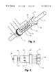
- FIG. 3is a perspective view of a part of said elongation pin.
- FIG. 4shows the energizing of the various parts of the elongation pin.
- FIG. 1shows a human lower leg 1 , in which a number of bones are present, with one bone 4 , 5 being provided with an elongation pin 3 .
- Said elongation pin 3has been fitted in order to elongate bone 4 , 5 by moving first bone portion 4 and second bone portion 5 , which together form bone 4 , 5 , apart in small steps at regular intervals for a certain period of time. Said moving apart of the two bone portions 4 , 5 is possible because bone 4 , 5 has been separated into two parts (sawn through) so as to form bone portions 4 , 5 .
- tissue 6will form between said bone portions 4 , 5 , which tissue 6 will grow during the time the two bone portions 4 , 5 are being moved relative to each other. Once the two bone portions 4 , 5 are no longer moved relative to each other, tissue 6 will change with time from an elastic tissue into a harder tissue, which connects the two bone portions 4 , 5 together. In this manner bone 4 , 5 can be elongated.
- the relative movement of the bone portions 4 , 5is effected by a device which has been implanted into the bone, which device consists of a first part 7 , which is substantially comprised of a metal, round bar, which is connected to first bone portion 4 by means of a fixing pin 8 , whereby said metal bar 7 extends to inside second bone portion 5 .
- the second part 9 of the deviceis fixed in second bone portion 5 by means of fixing pins 10 , with second part 9 surrounding bar 7 .
- Second part 9 of the deviceconsists of a first clamping member 11 and a second clamping member 12 , which are each capable of clampingly engaging bar 7 .
- the two clamping members 11 , 12are interconnected by means of a tubular connecting member 13 .
- Said connecting member 13may be fixed to clamping members 11 , 12 by means of a glued connection, a welded connection or a clamped connection, for example.
- first clamping member 11is connected to second bone portion 5 .
- second clamping member 12is connected to second bone portion 5 , as a result of which the forces occurring in second part 9 of the device will predominantly be pressure forces.
- FIG. 2shows the manner in which second part 9 of the device can move along bar 7 of said first part.
- Ring-shaped first clamping member 11 , tubular connecting member 13 and ring-shaped second clamping member 12are shown in sectional view in FIG. 2 .
- Clamping members 11 , 12 as well as connecting member 13are made of shape memory metal, namely a TiNi-alloy.
- the shape memory metal of first clamping member 11is composed and trained in such a manner that the dimension of the hole in the ring at the body temperature of 37° C. is such that bar 7 is not clamped down, whilst the shape of first clamping member 11 at a higher temperature, for example at 55° C., is such that said clamping member clamps down on bar 7 .
- the composition and the training of the shape memory metal of second clamping member 12is such that the second clamping member clamps down on bar 7 at the body temperature of 37° C.
- the releasing shape of second clamping member 12is obtained by cooling the shape memory metal of clamping member 12 down to a temperature of about 15° C.
- composition and the training of the shape memory metal of tubular connecting member 13is such that the length of said connecting member at the body temperature of 37° C. is less than at a higher temperature, for example 55° C.
- the difference in lengthmay amount to about 2 per cent, so that an elongation of 1 mm can be achieved with an overall length of 50 mm.
- Situations a-g in FIG. 2show the successive conditions of second part 9 of the device.
- the temperature of the shape memory metal of each of the members 11 , 12 , 13is the same as the body temperature of 37° C. This is likewise the case in situation g, but in situation g second member 11 , 12 , 13 has moved relative to bar 7 over a distance indicated by arrow 14 . Said movement along bar 7 is illustrated in situations b-f.
- first clamping member 11is heated until it clampingly engages bar 7 .
- second clamping member 12is cooled until it has its releasing shape, in which condition it no longer clampingly engages bar 7 , therefore.
- connecting member 13is heated to body temperature again, so that said clamping member 12 clampingly engages bar 7 .
- first clamping member 11has subsequently cooled down to body temperature, so that it no longer clampingly engages bar 7 (situation L)
- also connecting member 13is cooled down to body temperature, resulting in situation g, which corresponds with situation a, with this difference that second part 11 , 12 , 13 of the device has been moved a distance 14 relative to bar 7 .
- FIG. 3is a perspective view of a part of bar 7 and second part 9 of the device.
- Ring-shaped first member 11is enveloped by a resistance foil 15 , which is indicated diagrammatically, as are the connecting points for the current supply for heating the resistance foil.
- Ring-shaped second member 12is provided with two Peltier elements 16 , which are capable of cooling the shape memory metal of clamping member 12 when current is being supplied to said Peltier elements.
- the number of Peltier elementsmay also be larger than two. In that case they will act as a heat pump, whereby heat is discharged from the shape memory metal of clamping member 12 to the surroundings thereof. In this manner the shape memory metal of clamping member 12 can be cooled relative to the ambient temperature, which is the same as the body temperature of 37° C.
- Tubular connecting member 13which is positioned between the two clamping members 11 , 12 , is enveloped by a resistance foil diagrammatically indicated by block-shaped line 17 , which can be heated by supplying current thereto.
- the inside of the clamping member abutting against bar 7 , and/or the surface of bar 7may be provided with a special heat-insulating and/or friction-increasing coating.
- FIG. 4shows the energy supply of the device.
- Electric power supply 18is connected to a primary coil 19 , which is for example provided round the patient's lower leg.
- Primary coil 19is capable of transmitting energy, by means of an electromagnetic field, to secondary coil 20 , which is capable of charging the two batteries 21 . This makes it possible to feed a relatively large amount of energy to the device during a short period of time, whilst said electric energy can be transported to the device over a much longer period.
- Block 22indicates the control unit of the device, which unit is controlled by a control device present outside the body, which is in communication with control unit 22 , for example by means of radio waves.
- Said control unit 22is capable of transmitting electric energy to the (diagrammatically indicated) clamping members 11 , 12 and connecting member 13 , so that the shape memory metal of each of said members can be selectively heated (clamping member 11 and connecting member 13 ) or cooled (clamping member 12 ).
Landscapes
- Health & Medical Sciences (AREA)
- Orthopedic Medicine & Surgery (AREA)
- Surgery (AREA)
- Life Sciences & Earth Sciences (AREA)
- Heart & Thoracic Surgery (AREA)
- Nuclear Medicine, Radiotherapy & Molecular Imaging (AREA)
- Engineering & Computer Science (AREA)
- Biomedical Technology (AREA)
- Neurology (AREA)
- Medical Informatics (AREA)
- Molecular Biology (AREA)
- Animal Behavior & Ethology (AREA)
- General Health & Medical Sciences (AREA)
- Public Health (AREA)
- Veterinary Medicine (AREA)
- Prostheses (AREA)
- Surgical Instruments (AREA)
Abstract
Description
Claims (14)
Applications Claiming Priority (3)
| Application Number | Priority Date | Filing Date | Title |
|---|---|---|---|
| NL1004873ANL1004873C2 (en) | 1996-12-23 | 1996-12-23 | Device for moving two objects together. |
| NL1004873 | 1996-12-23 | ||
| PCT/NL1997/000706WO1998027885A1 (en) | 1996-12-23 | 1997-12-17 | Device for moving two objects relative to each other |
Publications (1)
| Publication Number | Publication Date |
|---|---|
| US6200317B1true US6200317B1 (en) | 2001-03-13 |
Family
ID=19764125
Family Applications (1)
| Application Number | Title | Priority Date | Filing Date |
|---|---|---|---|
| US09/331,673Expired - LifetimeUS6200317B1 (en) | 1996-12-23 | 1997-12-17 | Device for moving two objects relative to each other |
Country Status (7)
| Country | Link |
|---|---|
| US (1) | US6200317B1 (en) |
| EP (1) | EP0961586B1 (en) |
| JP (1) | JP2001511027A (en) |
| DE (1) | DE69730527T2 (en) |
| ES (1) | ES2227725T3 (en) |
| NL (1) | NL1004873C2 (en) |
| WO (1) | WO1998027885A1 (en) |
Cited By (82)
| Publication number | Priority date | Publication date | Assignee | Title |
|---|---|---|---|---|
| US6375638B2 (en)* | 1999-02-12 | 2002-04-23 | Medtronic Minimed, Inc. | Incremental motion pump mechanisms powered by shape memory alloy wire or the like |
| US20030198558A1 (en)* | 2002-04-22 | 2003-10-23 | Nason Clyde K. | Shape memory alloy wire driven positive displacement micropump with pulsatile output |
| US20040059331A1 (en)* | 2002-09-17 | 2004-03-25 | Visionmed, L.L.C. | Unilateral fixator |
| US20040097922A1 (en)* | 2002-11-14 | 2004-05-20 | Visionmed, L.L.C. | Method for a using fixator device |
| US20040138663A1 (en)* | 2001-05-23 | 2004-07-15 | Yona Kosashvili | Magnetically-actuable intramedullary device |
| US20050251109A1 (en)* | 2002-08-30 | 2005-11-10 | Arnaud Soubeiran | Device for locking/unlocking rotation in the organism |
| US20050261779A1 (en)* | 2003-11-17 | 2005-11-24 | Meyer Rudolf X | Expansible rod-type prosthesis and external magnetic apparatus |
| US20060004459A1 (en)* | 2004-06-30 | 2006-01-05 | Hazebrouck Stephen A | Adjustable orthopaedic prosthesis and associated method |
| US20060009767A1 (en)* | 2004-07-02 | 2006-01-12 | Kiester P D | Expandable rod system to treat scoliosis and method of using the same |
| US20060069447A1 (en)* | 2004-09-30 | 2006-03-30 | Disilvestro Mark R | Adjustable, remote-controllable orthopaedic prosthesis and associated method |
| US20060116775A1 (en)* | 1993-11-01 | 2006-06-01 | Biomet Manufacturing Corp. | Compliant fixation for pelvis |
| US20060129247A1 (en)* | 1993-11-01 | 2006-06-15 | Bioment Manufacturing Corp. | Intramedullary compliant fixation |
| US20060161261A1 (en)* | 2004-05-04 | 2006-07-20 | Biomet Manufacturing Corp. | Method and apparatus for constructing a modular acetabulum |
| US20060207495A1 (en)* | 2000-03-23 | 2006-09-21 | Petrakis Dennis N | Temperature activated systems |
| US20060260534A1 (en)* | 2001-03-23 | 2006-11-23 | Petrakis Dennis N | Temperature responsive systems |
| US7141073B2 (en) | 1993-11-01 | 2006-11-28 | Biomet, Inc. | Compliant fixation of external prosthesis |
| US20070173837A1 (en)* | 2005-11-18 | 2007-07-26 | William Marsh Rice University | Bone fixation and dynamization devices and methods |
| US20070179501A1 (en)* | 2006-01-13 | 2007-08-02 | Paul Firkins | Spinal Rod Support Kit |
| US20070270850A1 (en)* | 2006-04-28 | 2007-11-22 | Geissler William B | Osteotomy systems |
| US20070276378A1 (en)* | 2004-09-29 | 2007-11-29 | The Regents Of The University Of California | Apparatus and methods for magnetic alteration of anatomical features |
| US20080215037A1 (en)* | 2003-03-17 | 2008-09-04 | Petrakis Dennis N | Temperature responsive systems |
| US7485149B1 (en) | 2003-10-06 | 2009-02-03 | Biomet Manufacturing Corporation | Method and apparatus for use of a non-invasive expandable implant |
| US20090041085A1 (en)* | 2001-03-23 | 2009-02-12 | Petrakis Dennis N | Temperature responsive systems |
| US20090048632A1 (en)* | 2005-10-22 | 2009-02-19 | Paul Firkins | Spinal Support Rod Kit |
| US20090112262A1 (en)* | 2007-10-30 | 2009-04-30 | Scott Pool | Skeletal manipulation system |
| US20090198280A1 (en)* | 2007-10-24 | 2009-08-06 | Frank Spratt | Assembly for Orthopaedic Surgery |
| US20090222042A1 (en)* | 2005-10-22 | 2009-09-03 | Paul Firkins | Implant Kit For Supporting A Spinal Column |
| US7607402B2 (en) | 2001-03-23 | 2009-10-27 | Petrakis Dennis N | Temperature responsive systems |
| US20100049204A1 (en)* | 2006-10-03 | 2010-02-25 | Arnaud Soubeiran | Intracorporeal elongation device with a permanent magnet |
| US7670383B1 (en) | 2004-05-04 | 2010-03-02 | Biomet Manufacturing Corp. | Pubic catch |
| US20100063548A1 (en)* | 2008-07-07 | 2010-03-11 | Depuy International Ltd | Spinal Correction Method Using Shape Memory Spinal Rod |
| US20100094305A1 (en)* | 2008-10-13 | 2010-04-15 | Arvin Chang | Spinal distraction system |
| US20100121323A1 (en)* | 2008-11-10 | 2010-05-13 | Ellipse Technologies, Inc. | External adjustment device for distraction device |
| US20100125273A1 (en)* | 2007-04-30 | 2010-05-20 | Ao Technology Ag | Sleeve for a transfixation device for an external skeletal fixator |
| US20100217271A1 (en)* | 2009-02-23 | 2010-08-26 | Ellipse Technologies, Inc. | Spinal distraction system |
| US20100256640A1 (en)* | 2009-04-02 | 2010-10-07 | Zimmer, Inc. | Apparatus and method for prophylactic hip fixation |
| US20100318085A1 (en)* | 2007-03-13 | 2010-12-16 | Smith & Nephew, Inc. | Internal fixation devices |
| US20110004212A1 (en)* | 2008-02-27 | 2011-01-06 | Medshape Solutions Inc. | Intramedullary medical device and methods of use and manufacture |
| US20110060336A1 (en)* | 2009-09-04 | 2011-03-10 | Ellipse Technologies, Inc. | Bone growth device and method |
| US20110077651A1 (en)* | 2009-09-28 | 2011-03-31 | Zimmer, Inc. | Expandable intramedullary rod |
| US20110144756A1 (en)* | 2009-10-10 | 2011-06-16 | Bickley Barry T | Method and apparatus for restoring a joint, including the provision and use of a longitudinally-adjustable and rotationally-adjustable joint prosthesis |
| US7981025B2 (en) | 2006-10-20 | 2011-07-19 | Ellipse Technologies, Inc. | Adjustable implant and method of use |
| US20110178604A1 (en)* | 2010-01-18 | 2011-07-21 | Biomet Manufacturing Corp. | Expandable Endoprosthesis |
| US8348952B2 (en) | 2006-01-26 | 2013-01-08 | Depuy International Ltd. | System and method for cooling a spinal correction device comprising a shape memory material for corrective spinal surgery |
| US8551106B2 (en) | 2011-09-30 | 2013-10-08 | Arthrocare Corporation | Method and apparatus for installation of intramedullary medical device |
| US8715282B2 (en) | 2011-02-14 | 2014-05-06 | Ellipse Technologies, Inc. | System and method for altering rotational alignment of bone sections |
| US8915970B2 (en) | 2013-02-08 | 2014-12-23 | Biomet Manufacturing, Llc | Transdermal prosthesis |
| US8968415B2 (en) | 2012-02-07 | 2015-03-03 | Biomet Manufacturing, Llc | Implant fixation device |
| US9248043B2 (en) | 2010-06-30 | 2016-02-02 | Ellipse Technologies, Inc. | External adjustment device for distraction device |
| US9351771B2 (en) | 2013-02-08 | 2016-05-31 | Robert Gorsline | Systems, methods, and apparatuses for fusion, stabilization, or fixation of bones |
| US9827025B2 (en) | 2015-11-20 | 2017-11-28 | Globus Medical, Inc. | Expandable intramedullary systems and methods of using the same |
| US9855063B2 (en) | 2013-02-28 | 2018-01-02 | Jonathan Feibel | Systems, methods, and apparatuses for reaming bone elements |
| US9974581B2 (en) | 2015-11-20 | 2018-05-22 | Globus Medical, Inc. | Expandable intramedullary systems and methods of using the same |
| US10016220B2 (en) | 2011-11-01 | 2018-07-10 | Nuvasive Specialized Orthopedics, Inc. | Adjustable magnetic devices and methods of using same |
| US10092333B2 (en) | 2015-11-20 | 2018-10-09 | Globus Medical, Inc. | Expandable intramedullary systems and methods of using the same |
| US10238427B2 (en) | 2015-02-19 | 2019-03-26 | Nuvasive Specialized Orthopedics, Inc. | Systems and methods for vertebral adjustment |
| US10271885B2 (en) | 2014-12-26 | 2019-04-30 | Nuvasive Specialized Orthopedics, Inc. | Systems and methods for distraction |
| US10405891B2 (en) | 2010-08-09 | 2019-09-10 | Nuvasive Specialized Orthopedics, Inc. | Maintenance feature in magnetic implant |
| US10478232B2 (en) | 2009-04-29 | 2019-11-19 | Nuvasive Specialized Orthopedics, Inc. | Interspinous process device and method |
| US10617453B2 (en) | 2015-10-16 | 2020-04-14 | Nuvasive Specialized Orthopedics, Inc. | Adjustable devices for treating arthritis of the knee |
| US10743794B2 (en) | 2011-10-04 | 2020-08-18 | Nuvasive Specialized Orthopedics, Inc. | Devices and methods for non-invasive implant length sensing |
| US10751094B2 (en) | 2013-10-10 | 2020-08-25 | Nuvasive Specialized Orthopedics, Inc. | Adjustable spinal implant |
| US10835290B2 (en) | 2015-12-10 | 2020-11-17 | Nuvasive Specialized Orthopedics, Inc. | External adjustment device for distraction device |
| US10918425B2 (en) | 2016-01-28 | 2021-02-16 | Nuvasive Specialized Orthopedics, Inc. | System and methods for bone transport |
| US11191579B2 (en) | 2012-10-29 | 2021-12-07 | Nuvasive Specialized Orthopedics, Inc. | Adjustable devices for treating arthritis of the knee |
| US11202707B2 (en) | 2008-03-25 | 2021-12-21 | Nuvasive Specialized Orthopedics, Inc. | Adjustable implant system |
| US11241257B2 (en) | 2008-10-13 | 2022-02-08 | Nuvasive Specialized Orthopedics, Inc. | Spinal distraction system |
| US11246694B2 (en) | 2014-04-28 | 2022-02-15 | Nuvasive Specialized Orthopedics, Inc. | System for informational magnetic feedback in adjustable implants |
| USRE49061E1 (en) | 2012-10-18 | 2022-05-10 | Nuvasive Specialized Orthopedics, Inc. | Intramedullary implants for replacing lost bone |
| US11357547B2 (en) | 2014-10-23 | 2022-06-14 | Nuvasive Specialized Orthopedics Inc. | Remotely adjustable interactive bone reshaping implant |
| US11577097B2 (en) | 2019-02-07 | 2023-02-14 | Nuvasive Specialized Orthopedics, Inc. | Ultrasonic communication in medical devices |
| US11589901B2 (en) | 2019-02-08 | 2023-02-28 | Nuvasive Specialized Orthopedics, Inc. | External adjustment device |
| US11607223B2 (en) | 2017-06-30 | 2023-03-21 | The Regents Of The University Of California | Magnetic devices, systems, and methods |
| US11696836B2 (en) | 2013-08-09 | 2023-07-11 | Nuvasive, Inc. | Lordotic expandable interbody implant |
| US11737787B1 (en) | 2021-05-27 | 2023-08-29 | Nuvasive, Inc. | Bone elongating devices and methods of use |
| US11766252B2 (en) | 2013-07-31 | 2023-09-26 | Nuvasive Specialized Orthopedics, Inc. | Noninvasively adjustable suture anchors |
| US11801187B2 (en) | 2016-02-10 | 2023-10-31 | Nuvasive Specialized Orthopedics, Inc. | Systems and methods for controlling multiple surgical variables |
| US11806054B2 (en) | 2021-02-23 | 2023-11-07 | Nuvasive Specialized Orthopedics, Inc. | Adjustable implant, system and methods |
| US11839410B2 (en) | 2012-06-15 | 2023-12-12 | Nuvasive Inc. | Magnetic implants with improved anatomical compatibility |
| US11857226B2 (en) | 2013-03-08 | 2024-01-02 | Nuvasive Specialized Orthopedics | Systems and methods for ultrasonic detection of device distraction |
| US12023073B2 (en) | 2021-08-03 | 2024-07-02 | Nuvasive Specialized Orthopedics, Inc. | Adjustable implant |
| US12213708B2 (en) | 2020-09-08 | 2025-02-04 | Nuvasive Specialized Orthopedics, Inc. | Remote control module for adjustable implants |
Families Citing this family (5)
| Publication number | Priority date | Publication date | Assignee | Title |
|---|---|---|---|---|
| DE19829523A1 (en)* | 1998-07-02 | 2000-01-05 | Michael Butsch | Distraction device for moving apart a one- or two-part, possibly separate bone |
| JP5871464B2 (en)* | 2007-04-19 | 2016-03-01 | スミス アンド ネフュー インコーポレーテッドSmith & Nephew,Inc. | Oriented polymer device |
| DE102007026404A1 (en)* | 2007-06-07 | 2008-12-18 | Hexamed Gmbh | Ring fixator for external fixation and reposition of bone fragments, has two ring that are held at distance at which bones are fastened by guided wires |
| AU2009310439B2 (en)* | 2008-10-31 | 2016-05-26 | Implantica Patent Ltd. | Device and method for bone adjustment with anchoring function |
| KR102589248B1 (en)* | 2020-06-19 | 2023-10-16 | 주식회사 제일메디칼코퍼레이션 | Metal fixed support in bone marrow steel with rotation and anti-breakage of fractured bones |
Citations (6)
| Publication number | Priority date | Publication date | Assignee | Title |
|---|---|---|---|---|
| US4262665A (en)* | 1979-06-27 | 1981-04-21 | Roalstad W L | Intramedullary compression device |
| WO1990015928A1 (en) | 1989-06-21 | 1990-12-27 | Johnson Service Company | A shape memory actuator |
| JPH06343276A (en)* | 1993-05-31 | 1994-12-13 | Nippondenso Co Ltd | Moving apparatus |
| US5415660A (en)* | 1994-01-07 | 1995-05-16 | Regents Of The University Of Minnesota | Implantable limb lengthening nail driven by a shape memory alloy |
| FR2726460A1 (en) | 1994-11-04 | 1996-05-10 | Medinov Sa | Medical prosthesis for insertion into leg bone to extend length |
| US5704938A (en)* | 1996-03-27 | 1998-01-06 | Volunteers For Medical Engineering | Implantable bone lengthening apparatus using a drive gear mechanism |
- 1996
- 1996-12-23NLNL1004873Apatent/NL1004873C2/ennot_activeIP Right Cessation
- 1997
- 1997-12-17USUS09/331,673patent/US6200317B1/ennot_activeExpired - Lifetime
- 1997-12-17ESES97950501Tpatent/ES2227725T3/ennot_activeExpired - Lifetime
- 1997-12-17WOPCT/NL1997/000706patent/WO1998027885A1/enactiveIP Right Grant
- 1997-12-17DEDE69730527Tpatent/DE69730527T2/ennot_activeExpired - Lifetime
- 1997-12-17JPJP52864498Apatent/JP2001511027A/enactivePending
- 1997-12-17EPEP97950501Apatent/EP0961586B1/ennot_activeExpired - Lifetime
Patent Citations (6)
| Publication number | Priority date | Publication date | Assignee | Title |
|---|---|---|---|---|
| US4262665A (en)* | 1979-06-27 | 1981-04-21 | Roalstad W L | Intramedullary compression device |
| WO1990015928A1 (en) | 1989-06-21 | 1990-12-27 | Johnson Service Company | A shape memory actuator |
| JPH06343276A (en)* | 1993-05-31 | 1994-12-13 | Nippondenso Co Ltd | Moving apparatus |
| US5415660A (en)* | 1994-01-07 | 1995-05-16 | Regents Of The University Of Minnesota | Implantable limb lengthening nail driven by a shape memory alloy |
| FR2726460A1 (en) | 1994-11-04 | 1996-05-10 | Medinov Sa | Medical prosthesis for insertion into leg bone to extend length |
| US5704938A (en)* | 1996-03-27 | 1998-01-06 | Volunteers For Medical Engineering | Implantable bone lengthening apparatus using a drive gear mechanism |
Non-Patent Citations (1)
| Title |
|---|
| Patent Abstracts of Japan, vol. 95, No. 3, Apr. 28, 1995; JP 06 343276. |
Cited By (205)
| Publication number | Priority date | Publication date | Assignee | Title |
|---|---|---|---|---|
| US20060116775A1 (en)* | 1993-11-01 | 2006-06-01 | Biomet Manufacturing Corp. | Compliant fixation for pelvis |
| US7722678B2 (en) | 1993-11-01 | 2010-05-25 | Biomet Manufacturing Corp. | Intramedullary compliant fixation |
| US7476254B2 (en) | 1993-11-01 | 2009-01-13 | Biomet Manufacturing Corporation | Compliant fixation for pelvis |
| US7141073B2 (en) | 1993-11-01 | 2006-11-28 | Biomet, Inc. | Compliant fixation of external prosthesis |
| US20060129247A1 (en)* | 1993-11-01 | 2006-06-15 | Bioment Manufacturing Corp. | Intramedullary compliant fixation |
| US6375638B2 (en)* | 1999-02-12 | 2002-04-23 | Medtronic Minimed, Inc. | Incremental motion pump mechanisms powered by shape memory alloy wire or the like |
| US7455668B2 (en) | 2000-03-23 | 2008-11-25 | Petrakis Dennis N | Temperature activated systems |
| US7287485B2 (en) | 2000-03-23 | 2007-10-30 | Petrakis Dennis N | Temperature activated systems |
| US20060207495A1 (en)* | 2000-03-23 | 2006-09-21 | Petrakis Dennis N | Temperature activated systems |
| US7655001B2 (en) | 2001-03-23 | 2010-02-02 | Petrakis Dennis N | Temperature responsive systems |
| US20090041085A1 (en)* | 2001-03-23 | 2009-02-12 | Petrakis Dennis N | Temperature responsive systems |
| US7607402B2 (en) | 2001-03-23 | 2009-10-27 | Petrakis Dennis N | Temperature responsive systems |
| US7445616B2 (en) | 2001-03-23 | 2008-11-04 | Petrakis Dennis N | Temperature responsive systems |
| US20060260534A1 (en)* | 2001-03-23 | 2006-11-23 | Petrakis Dennis N | Temperature responsive systems |
| US8172458B2 (en) | 2001-03-23 | 2012-05-08 | Petrakis Dennis N | Temperature responsive systems |
| US7135022B2 (en)* | 2001-05-23 | 2006-11-14 | Orthogon 2003 Ltd. | Magnetically-actuable intramedullary device |
| US20040138663A1 (en)* | 2001-05-23 | 2004-07-15 | Yona Kosashvili | Magnetically-actuable intramedullary device |
| US7052251B2 (en) | 2002-04-22 | 2006-05-30 | Medtronic Minimed, Inc. | Shape memory alloy wire driven positive displacement micropump with pulsatile output |
| US20030198558A1 (en)* | 2002-04-22 | 2003-10-23 | Nason Clyde K. | Shape memory alloy wire driven positive displacement micropump with pulsatile output |
| US8574215B2 (en) | 2002-04-22 | 2013-11-05 | Medtronic Minimed, Inc. | Shape memory alloy wire driven positive displacement micropump with pulsatile output |
| US7226278B2 (en) | 2002-04-22 | 2007-06-05 | Medtronic Minimed, Inc. | Shape memory alloy wire driven positive displacement micropump with pulsatile output |
| US20070166170A1 (en)* | 2002-04-22 | 2007-07-19 | Medtronic Minimed, Inc. | Shape memory alloy wire driven positive displacement micropump with pulsatile output |
| US20060013716A1 (en)* | 2002-04-22 | 2006-01-19 | Medtronic Minimed, Inc. | Shape memory alloy wire driven positive displacement micropump with pulsatile output |
| US20050251109A1 (en)* | 2002-08-30 | 2005-11-10 | Arnaud Soubeiran | Device for locking/unlocking rotation in the organism |
| US8388619B2 (en) | 2002-09-17 | 2013-03-05 | Sixfix Inc. | Unilateral fixator |
| US7282052B2 (en) | 2002-09-17 | 2007-10-16 | Ebi, L.P. | Unilateral fixator |
| US20040059331A1 (en)* | 2002-09-17 | 2004-03-25 | Visionmed, L.L.C. | Unilateral fixator |
| US20070282338A1 (en)* | 2002-09-17 | 2007-12-06 | Ebi, L.P. | Unilateral fixator |
| US20110103676A1 (en)* | 2002-11-14 | 2011-05-05 | Extraortho, Inc. | Method for using a fixator device |
| US8419732B2 (en) | 2002-11-14 | 2013-04-16 | Sixfix, Inc. | Method for using a fixator device |
| US20040097922A1 (en)* | 2002-11-14 | 2004-05-20 | Visionmed, L.L.C. | Method for a using fixator device |
| US20080215037A1 (en)* | 2003-03-17 | 2008-09-04 | Petrakis Dennis N | Temperature responsive systems |
| US7476224B2 (en) | 2003-03-17 | 2009-01-13 | Petrakis Dennis N | Temperature responsive systems |
| US7485149B1 (en) | 2003-10-06 | 2009-02-03 | Biomet Manufacturing Corporation | Method and apparatus for use of a non-invasive expandable implant |
| US20050261779A1 (en)* | 2003-11-17 | 2005-11-24 | Meyer Rudolf X | Expansible rod-type prosthesis and external magnetic apparatus |
| US7670383B1 (en) | 2004-05-04 | 2010-03-02 | Biomet Manufacturing Corp. | Pubic catch |
| US8048166B2 (en) | 2004-05-04 | 2011-11-01 | Biomet Manufacturing Corp. | Method and apparatus for constructing a modular acetabulum |
| US20060161261A1 (en)* | 2004-05-04 | 2006-07-20 | Biomet Manufacturing Corp. | Method and apparatus for constructing a modular acetabulum |
| US20060004459A1 (en)* | 2004-06-30 | 2006-01-05 | Hazebrouck Stephen A | Adjustable orthopaedic prosthesis and associated method |
| US7481841B2 (en) | 2004-06-30 | 2009-01-27 | Depuy Products, Inc. | Adjustable orthopaedic prosthesis and associated method |
| US20090204154A1 (en)* | 2004-07-02 | 2009-08-13 | Ellipse Technologies, Inc. | expandable rod system to treat scoliosis and method of using the same |
| US8343192B2 (en) | 2004-07-02 | 2013-01-01 | Ellipse Technologies, Inc. | Expandable rod system to treat scoliosis and method of using the same |
| US7955357B2 (en) | 2004-07-02 | 2011-06-07 | Ellipse Technologies, Inc. | Expandable rod system to treat scoliosis and method of using the same |
| US11712268B2 (en) | 2004-07-02 | 2023-08-01 | Nuvasive Specialized Orthopedics, Inc. | Expandable rod system to treat scoliosis and method of using the same |
| US9011499B1 (en)* | 2004-07-02 | 2015-04-21 | Ellipse Technologies, Inc | Expandable rod system to treat scoliosis and method of using the same |
| US20150134008A1 (en)* | 2004-07-02 | 2015-05-14 | Ellipse Technologies, Inc | Expandable rod system to treat scoliosis and method of using the same |
| US11357549B2 (en) | 2004-07-02 | 2022-06-14 | Nuvasive Specialized Orthopedics, Inc. | Expandable rod system to treat scoliosis and method of using the same |
| US20060009767A1 (en)* | 2004-07-02 | 2006-01-12 | Kiester P D | Expandable rod system to treat scoliosis and method of using the same |
| US9398925B2 (en) | 2004-07-02 | 2016-07-26 | Nuvasive Specialized Orthopedics, Inc. | Expandable rod system to treat scoliosis and method of using the same |
| US10016221B2 (en) | 2004-07-02 | 2018-07-10 | Nuvasive Specialized Orthopedics, Inc. | Expandable rod system to treat scoliosis and method of using the same |
| US8852236B2 (en) | 2004-07-02 | 2014-10-07 | Ellipse Technologies, Inc. | Expandable rod system to treat scoliosis and method of using the same |
| US20070276378A1 (en)* | 2004-09-29 | 2007-11-29 | The Regents Of The University Of California | Apparatus and methods for magnetic alteration of anatomical features |
| US8439915B2 (en)* | 2004-09-29 | 2013-05-14 | The Regents Of The University Of California | Apparatus and methods for magnetic alteration of anatomical features |
| US7559951B2 (en) | 2004-09-30 | 2009-07-14 | Depuy Products, Inc. | Adjustable, remote-controllable orthopaedic prosthesis and associated method |
| US8419801B2 (en) | 2004-09-30 | 2013-04-16 | DePuy Synthes Products, LLC | Adjustable, remote-controllable orthopaedic prosthesis and associated method |
| US20060069447A1 (en)* | 2004-09-30 | 2006-03-30 | Disilvestro Mark R | Adjustable, remote-controllable orthopaedic prosthesis and associated method |
| US8414614B2 (en) | 2005-10-22 | 2013-04-09 | Depuy International Ltd | Implant kit for supporting a spinal column |
| US20090222042A1 (en)* | 2005-10-22 | 2009-09-03 | Paul Firkins | Implant Kit For Supporting A Spinal Column |
| US20090048632A1 (en)* | 2005-10-22 | 2009-02-19 | Paul Firkins | Spinal Support Rod Kit |
| US20070173837A1 (en)* | 2005-11-18 | 2007-07-26 | William Marsh Rice University | Bone fixation and dynamization devices and methods |
| US8425563B2 (en) | 2006-01-13 | 2013-04-23 | Depuy International Ltd. | Spinal rod support kit |
| US20070179501A1 (en)* | 2006-01-13 | 2007-08-02 | Paul Firkins | Spinal Rod Support Kit |
| US8348952B2 (en) | 2006-01-26 | 2013-01-08 | Depuy International Ltd. | System and method for cooling a spinal correction device comprising a shape memory material for corrective spinal surgery |
| US20070270850A1 (en)* | 2006-04-28 | 2007-11-22 | Geissler William B | Osteotomy systems |
| US8652142B2 (en) | 2006-04-28 | 2014-02-18 | Acumed Llc | Osteotomy systems |
| US8632548B2 (en)* | 2006-10-03 | 2014-01-21 | Arnaud Soubeiran | Intracorporeal elongation device with a permanent magnet |
| US20100049204A1 (en)* | 2006-10-03 | 2010-02-25 | Arnaud Soubeiran | Intracorporeal elongation device with a permanent magnet |
| US10039661B2 (en) | 2006-10-20 | 2018-08-07 | Nuvasive Specialized Orthopedics, Inc. | Adjustable implant and method of use |
| US9526650B2 (en) | 2006-10-20 | 2016-12-27 | Nuvasive Specialized Orthopedics, Inc. | Adjustable implant and method of use |
| US20110237861A1 (en)* | 2006-10-20 | 2011-09-29 | Ellipse Technologies, Inc. | Adjustable implant and method of use |
| US8715159B2 (en) | 2006-10-20 | 2014-05-06 | Ellipse Technologies, Inc. | Adjustable implant and method of use |
| US11234849B2 (en) | 2006-10-20 | 2022-02-01 | Nuvasive Specialized Orthopedics, Inc. | Adjustable implant and method of use |
| US9271857B2 (en) | 2006-10-20 | 2016-03-01 | Ellipse Technologies, Inc. | Adjustable implant and method of use |
| US7981025B2 (en) | 2006-10-20 | 2011-07-19 | Ellipse Technologies, Inc. | Adjustable implant and method of use |
| US8808163B2 (en) | 2006-10-20 | 2014-08-19 | Ellipse Technologies, Inc. | Adjustable implant and method of use |
| US11672684B2 (en) | 2006-10-20 | 2023-06-13 | Nuvasive Specialized Orthopedics, Inc. | Adjustable implant and method of use |
| US20100318085A1 (en)* | 2007-03-13 | 2010-12-16 | Smith & Nephew, Inc. | Internal fixation devices |
| EP2139412B1 (en)* | 2007-04-30 | 2015-08-26 | AO Technology AG | Transfixation device for an external skeletal fixator |
| US20100125273A1 (en)* | 2007-04-30 | 2010-05-20 | Ao Technology Ag | Sleeve for a transfixation device for an external skeletal fixator |
| AU2007352211B2 (en)* | 2007-04-30 | 2013-05-02 | Ao Technology Ag | Sleeve for a transfixation device for an external skeletal fixator |
| US9510860B2 (en)* | 2007-04-30 | 2016-12-06 | Ao Technology Ag | Sleeve for a transfixation device for an external skeletal fixator |
| US8430914B2 (en) | 2007-10-24 | 2013-04-30 | Depuy Spine, Inc. | Assembly for orthopaedic surgery |
| US20090198280A1 (en)* | 2007-10-24 | 2009-08-06 | Frank Spratt | Assembly for Orthopaedic Surgery |
| US8057472B2 (en) | 2007-10-30 | 2011-11-15 | Ellipse Technologies, Inc. | Skeletal manipulation method |
| US20090112262A1 (en)* | 2007-10-30 | 2009-04-30 | Scott Pool | Skeletal manipulation system |
| US9271781B2 (en) | 2007-10-30 | 2016-03-01 | Ellipse Technologies, Inc. | Skeletal manipulation method |
| US9179960B2 (en) | 2007-10-30 | 2015-11-10 | Ellipse Technologies, Inc. | Skeletal manipulation method |
| US9693813B2 (en) | 2007-10-30 | 2017-07-04 | Nuvasive Specialized Orthopedics, Inc. | Skeletal manipulation method |
| US11172972B2 (en) | 2007-10-30 | 2021-11-16 | Nuvasive Specialized Orthopedics, Inc. | Skeletal manipulation method |
| US8419734B2 (en) | 2007-10-30 | 2013-04-16 | Ellipse Technologies, Inc. | Skeletal manipulation method |
| US20090112263A1 (en)* | 2007-10-30 | 2009-04-30 | Scott Pool | Skeletal manipulation system |
| US20090112207A1 (en)* | 2007-10-30 | 2009-04-30 | Blair Walker | Skeletal manipulation method |
| US11871974B2 (en) | 2007-10-30 | 2024-01-16 | Nuvasive Specialized Orthopedics, Inc. | Skeletal manipulation method |
| US10349995B2 (en) | 2007-10-30 | 2019-07-16 | Nuvasive Specialized Orthopedics, Inc. | Skeletal manipulation method |
| US8491583B2 (en)* | 2008-02-27 | 2013-07-23 | Medshape, Inc. | Intramedullary medical device and methods of use and manufacture |
| US20110004212A1 (en)* | 2008-02-27 | 2011-01-06 | Medshape Solutions Inc. | Intramedullary medical device and methods of use and manufacture |
| US11202707B2 (en) | 2008-03-25 | 2021-12-21 | Nuvasive Specialized Orthopedics, Inc. | Adjustable implant system |
| US12076241B2 (en) | 2008-03-25 | 2024-09-03 | Nuvasive Specialized Orthopedics, Inc. | Adjustable implant system |
| US20100063548A1 (en)* | 2008-07-07 | 2010-03-11 | Depuy International Ltd | Spinal Correction Method Using Shape Memory Spinal Rod |
| US20100094303A1 (en)* | 2008-10-13 | 2010-04-15 | Arvin Chang | Spinal distraction system |
| US20100094305A1 (en)* | 2008-10-13 | 2010-04-15 | Arvin Chang | Spinal distraction system |
| US11925389B2 (en) | 2008-10-13 | 2024-03-12 | Nuvasive Specialized Orthopedics, Inc. | Spinal distraction system |
| US20100094306A1 (en)* | 2008-10-13 | 2010-04-15 | Arvin Chang | Spinal distraction system |
| US20100094304A1 (en)* | 2008-10-13 | 2010-04-15 | Scott Pool | Spinal distraction system |
| US20100094302A1 (en)* | 2008-10-13 | 2010-04-15 | Scott Pool | Spinal distraction system |
| US11241257B2 (en) | 2008-10-13 | 2022-02-08 | Nuvasive Specialized Orthopedics, Inc. | Spinal distraction system |
| US10729470B2 (en) | 2008-11-10 | 2020-08-04 | Nuvasive Specialized Orthopedics, Inc. | External adjustment device for distraction device |
| US11974782B2 (en) | 2008-11-10 | 2024-05-07 | Nuvasive Specialized Orthopedics, Inc. | External adjustment device for distraction device |
| US8382756B2 (en) | 2008-11-10 | 2013-02-26 | Ellipse Technologies, Inc. | External adjustment device for distraction device |
| US20100121323A1 (en)* | 2008-11-10 | 2010-05-13 | Ellipse Technologies, Inc. | External adjustment device for distraction device |
| US8974463B2 (en) | 2009-02-23 | 2015-03-10 | Ellipse Technologies, Inc. | Non-invasive adjustable distraction system |
| US9848914B2 (en) | 2009-02-23 | 2017-12-26 | Nuvasive Specialized Orthopedics, Inc. | Non-invasive adjustable distraction system |
| US11304729B2 (en) | 2009-02-23 | 2022-04-19 | Nuvasive Specialized Orthhopedics, Inc. | Non-invasive adjustable distraction system |
| US10517643B2 (en) | 2009-02-23 | 2019-12-31 | Nuvasive Specialized Orthopedics, Inc. | Non-invasive adjustable distraction system |
| US11918254B2 (en) | 2009-02-23 | 2024-03-05 | Nuvasive Specialized Orthopedics Inc. | Adjustable implant system |
| US8197490B2 (en) | 2009-02-23 | 2012-06-12 | Ellipse Technologies, Inc. | Non-invasive adjustable distraction system |
| US20100217271A1 (en)* | 2009-02-23 | 2010-08-26 | Ellipse Technologies, Inc. | Spinal distraction system |
| US8012155B2 (en) | 2009-04-02 | 2011-09-06 | Zimmer, Inc. | Apparatus and method for prophylactic hip fixation |
| US20100256640A1 (en)* | 2009-04-02 | 2010-10-07 | Zimmer, Inc. | Apparatus and method for prophylactic hip fixation |
| US11602380B2 (en) | 2009-04-29 | 2023-03-14 | Nuvasive Specialized Orthopedics, Inc. | Interspinous process device and method |
| US10478232B2 (en) | 2009-04-29 | 2019-11-19 | Nuvasive Specialized Orthopedics, Inc. | Interspinous process device and method |
| US11207110B2 (en) | 2009-09-04 | 2021-12-28 | Nuvasive Specialized Orthopedics, Inc. | Bone growth device and method |
| US8449543B2 (en) | 2009-09-04 | 2013-05-28 | Ellipse Technologies, Inc. | Bone growth device and method |
| US11944358B2 (en) | 2009-09-04 | 2024-04-02 | Nuvasive Specialized Orthopedics, Inc. | Bone growth device and method |
| US20110060336A1 (en)* | 2009-09-04 | 2011-03-10 | Ellipse Technologies, Inc. | Bone growth device and method |
| US20110077651A1 (en)* | 2009-09-28 | 2011-03-31 | Zimmer, Inc. | Expandable intramedullary rod |
| US8545499B2 (en) | 2009-09-28 | 2013-10-01 | Zimmer, Inc. | Expandable intramedullary rod |
| US8623092B2 (en)* | 2009-10-10 | 2014-01-07 | Simplicity Orthopedics, Inc. | Method and apparatus for restoring a joint, including the provision and use of a longitudinally-adjustable and rotationally-adjustable joint prosthesis |
| US20140324185A1 (en)* | 2009-10-10 | 2014-10-30 | Simplicity Orthopedics, Inc. | Method and apparatus for restoring a joint, including the provision and use of a longitudinally-adjustable and rotationally-adjustable joint prosthesis |
| US20110144756A1 (en)* | 2009-10-10 | 2011-06-16 | Bickley Barry T | Method and apparatus for restoring a joint, including the provision and use of a longitudinally-adjustable and rotationally-adjustable joint prosthesis |
| US9474618B2 (en)* | 2009-10-10 | 2016-10-25 | Simplicity Orthopedics, Inc. | Method and apparatus for restoring a joint, including the provision and use of a longitudinally-adjustable and rotationally-adjustable joint prosthesis |
| US20110178604A1 (en)* | 2010-01-18 | 2011-07-21 | Biomet Manufacturing Corp. | Expandable Endoprosthesis |
| US12178477B2 (en) | 2010-06-30 | 2024-12-31 | Globus Medical Inc. | External adjustment device for distraction system |
| US10660675B2 (en) | 2010-06-30 | 2020-05-26 | Nuvasive Specialized Orthopedics, Inc. | External adjustment device for distraction device |
| US11497530B2 (en) | 2010-06-30 | 2022-11-15 | Nuvasive Specialized Orthopedics, Inc. | External adjustment device for distraction device |
| US9248043B2 (en) | 2010-06-30 | 2016-02-02 | Ellipse Technologies, Inc. | External adjustment device for distraction device |
| US10405891B2 (en) | 2010-08-09 | 2019-09-10 | Nuvasive Specialized Orthopedics, Inc. | Maintenance feature in magnetic implant |
| US8715282B2 (en) | 2011-02-14 | 2014-05-06 | Ellipse Technologies, Inc. | System and method for altering rotational alignment of bone sections |
| US10105167B2 (en) | 2011-02-14 | 2018-10-23 | Nuvasive Specialized Orthopedics, Inc. | System and method for altering rotational alignment of bone sections |
| US10646262B2 (en) | 2011-02-14 | 2020-05-12 | Nuvasive Specialized Orthopedics, Inc. | System and method for altering rotational alignment of bone sections |
| US8852187B2 (en) | 2011-02-14 | 2014-10-07 | Ellipse Technologies, Inc. | Variable length device and method |
| US9393117B2 (en) | 2011-02-14 | 2016-07-19 | Nuvasive Specialized Orthopedics, Inc. | System and method for altering rotational alignment of bone sections |
| US11406432B2 (en) | 2011-02-14 | 2022-08-09 | Nuvasive Specialized Orthopedics, Inc. | System and method for altering rotational alignment of bone sections |
| US12290290B2 (en) | 2011-02-14 | 2025-05-06 | Nuvasive, Inc. | System and method for altering rotational alignment of bone sections |
| US9393119B2 (en) | 2011-02-14 | 2016-07-19 | Nuvasive Specialized Orthopedics, Inc. | Variable length device and method |
| US8551106B2 (en) | 2011-09-30 | 2013-10-08 | Arthrocare Corporation | Method and apparatus for installation of intramedullary medical device |
| US10743794B2 (en) | 2011-10-04 | 2020-08-18 | Nuvasive Specialized Orthopedics, Inc. | Devices and methods for non-invasive implant length sensing |
| US11445939B2 (en) | 2011-10-04 | 2022-09-20 | Nuvasive Specialized Orthopedics, Inc. | Devices and methods for non-invasive implant length sensing |
| US10016220B2 (en) | 2011-11-01 | 2018-07-10 | Nuvasive Specialized Orthopedics, Inc. | Adjustable magnetic devices and methods of using same |
| US11123107B2 (en) | 2011-11-01 | 2021-09-21 | Nuvasive Specialized Orthopedics, Inc. | Adjustable magnetic devices and methods of using same |
| US10349982B2 (en) | 2011-11-01 | 2019-07-16 | Nuvasive Specialized Orthopedics, Inc. | Adjustable magnetic devices and methods of using same |
| US11918255B2 (en) | 2011-11-01 | 2024-03-05 | Nuvasive Specialized Orthopedics Inc. | Adjustable magnetic devices and methods of using same |
| US8968415B2 (en) | 2012-02-07 | 2015-03-03 | Biomet Manufacturing, Llc | Implant fixation device |
| US11839410B2 (en) | 2012-06-15 | 2023-12-12 | Nuvasive Inc. | Magnetic implants with improved anatomical compatibility |
| USRE49720E1 (en) | 2012-10-18 | 2023-11-07 | Nuvasive Specialized Orthopedics, Inc. | Intramedullary implants for replacing lost bone |
| USRE49061E1 (en) | 2012-10-18 | 2022-05-10 | Nuvasive Specialized Orthopedics, Inc. | Intramedullary implants for replacing lost bone |
| US11871971B2 (en) | 2012-10-29 | 2024-01-16 | Nuvasive Specialized Orthopedics, Inc. | Adjustable devices for treating arthritis of the knee |
| US11191579B2 (en) | 2012-10-29 | 2021-12-07 | Nuvasive Specialized Orthopedics, Inc. | Adjustable devices for treating arthritis of the knee |
| US11213330B2 (en) | 2012-10-29 | 2022-01-04 | Nuvasive Specialized Orthopedics, Inc. | Adjustable devices for treating arthritis of the knee |
| US8915970B2 (en) | 2013-02-08 | 2014-12-23 | Biomet Manufacturing, Llc | Transdermal prosthesis |
| US9351771B2 (en) | 2013-02-08 | 2016-05-31 | Robert Gorsline | Systems, methods, and apparatuses for fusion, stabilization, or fixation of bones |
| US9855063B2 (en) | 2013-02-28 | 2018-01-02 | Jonathan Feibel | Systems, methods, and apparatuses for reaming bone elements |
| US11857226B2 (en) | 2013-03-08 | 2024-01-02 | Nuvasive Specialized Orthopedics | Systems and methods for ultrasonic detection of device distraction |
| US12329374B2 (en) | 2013-07-31 | 2025-06-17 | Nuvasive Specialized Orthopedics Inc. | Noninvasively adjustable suture anchors |
| US11766252B2 (en) | 2013-07-31 | 2023-09-26 | Nuvasive Specialized Orthopedics, Inc. | Noninvasively adjustable suture anchors |
| US12213893B2 (en) | 2013-08-09 | 2025-02-04 | Nuvasive, Inc. | Lordotic expandable interbody implant and method of using same |
| US11696836B2 (en) | 2013-08-09 | 2023-07-11 | Nuvasive, Inc. | Lordotic expandable interbody implant |
| US11576702B2 (en) | 2013-10-10 | 2023-02-14 | Nuvasive Specialized Orthopedics, Inc. | Adjustable spinal implant |
| US10751094B2 (en) | 2013-10-10 | 2020-08-25 | Nuvasive Specialized Orthopedics, Inc. | Adjustable spinal implant |
| US11246694B2 (en) | 2014-04-28 | 2022-02-15 | Nuvasive Specialized Orthopedics, Inc. | System for informational magnetic feedback in adjustable implants |
| US12226127B2 (en) | 2014-10-23 | 2025-02-18 | Nuvasive Specialized Orthopedics, Inc. | Remotely adjustable interactive implantable device |
| US11357547B2 (en) | 2014-10-23 | 2022-06-14 | Nuvasive Specialized Orthopedics Inc. | Remotely adjustable interactive bone reshaping implant |
| US11963705B2 (en) | 2014-12-26 | 2024-04-23 | Nuvasive Specialized Orthopedics, Inc. | Systems and methods for distraction |
| US11890043B2 (en) | 2014-12-26 | 2024-02-06 | Nuvasive Specialized Orthopedics, Inc. | Systems and methods for distraction |
| US10271885B2 (en) | 2014-12-26 | 2019-04-30 | Nuvasive Specialized Orthopedics, Inc. | Systems and methods for distraction |
| US11439449B2 (en) | 2014-12-26 | 2022-09-13 | Nuvasive Specialized Orthopedics, Inc. | Systems and methods for distraction |
| US12076051B2 (en) | 2015-02-19 | 2024-09-03 | Nuvasive Specialized Orthopedics, Inc. | Systems and methods for vertebral adjustment |
| US10238427B2 (en) | 2015-02-19 | 2019-03-26 | Nuvasive Specialized Orthopedics, Inc. | Systems and methods for vertebral adjustment |
| US11612416B2 (en) | 2015-02-19 | 2023-03-28 | Nuvasive Specialized Orthopedics, Inc. | Systems and methods for vertebral adjustment |
| US11596456B2 (en) | 2015-10-16 | 2023-03-07 | Nuvasive Specialized Orthopedics, Inc. | Adjustable devices for treating arthritis of the knee |
| US10617453B2 (en) | 2015-10-16 | 2020-04-14 | Nuvasive Specialized Orthopedics, Inc. | Adjustable devices for treating arthritis of the knee |
| US9827025B2 (en) | 2015-11-20 | 2017-11-28 | Globus Medical, Inc. | Expandable intramedullary systems and methods of using the same |
| US10828074B2 (en) | 2015-11-20 | 2020-11-10 | Globus Medical, Inc. | Expandalbe intramedullary systems and methods of using the same |
| US11759241B2 (en) | 2015-11-20 | 2023-09-19 | Audubon | Expandable intramedullary systems and methods of using the same |
| US10111691B2 (en) | 2015-11-20 | 2018-10-30 | Globus Medical, Inc. | Expandable intramedullary systems and methods of using the same |
| US10092333B2 (en) | 2015-11-20 | 2018-10-09 | Globus Medical, Inc. | Expandable intramedullary systems and methods of using the same |
| US12310637B2 (en) | 2015-11-20 | 2025-05-27 | Globus Medical, Inc. | Expandable intramedullary systems and methods of using the same |
| US9974581B2 (en) | 2015-11-20 | 2018-05-22 | Globus Medical, Inc. | Expandable intramedullary systems and methods of using the same |
| US10835290B2 (en) | 2015-12-10 | 2020-11-17 | Nuvasive Specialized Orthopedics, Inc. | External adjustment device for distraction device |
| US11504162B2 (en) | 2015-12-10 | 2022-11-22 | Nuvasive Specialized Orthopedics, Inc. | External adjustment device for distraction device |
| US12185982B2 (en) | 2015-12-10 | 2025-01-07 | Globus Medical Inc. | External adjustment device for distraction device |
| US10918425B2 (en) | 2016-01-28 | 2021-02-16 | Nuvasive Specialized Orthopedics, Inc. | System and methods for bone transport |
| US11801187B2 (en) | 2016-02-10 | 2023-10-31 | Nuvasive Specialized Orthopedics, Inc. | Systems and methods for controlling multiple surgical variables |
| US12263128B2 (en) | 2016-02-10 | 2025-04-01 | Nuvasive Specialized Orthopedics, Inc. | Systems and methods for controlling multiple surgical variables |
| US11607223B2 (en) | 2017-06-30 | 2023-03-21 | The Regents Of The University Of California | Magnetic devices, systems, and methods |
| US11577097B2 (en) | 2019-02-07 | 2023-02-14 | Nuvasive Specialized Orthopedics, Inc. | Ultrasonic communication in medical devices |
| US12274896B2 (en) | 2019-02-07 | 2025-04-15 | Nuvasive Specialized Orthopedics, Inc. | Ultrasonic communication in medical devices |
| US11589901B2 (en) | 2019-02-08 | 2023-02-28 | Nuvasive Specialized Orthopedics, Inc. | External adjustment device |
| US12213708B2 (en) | 2020-09-08 | 2025-02-04 | Nuvasive Specialized Orthopedics, Inc. | Remote control module for adjustable implants |
| US11806054B2 (en) | 2021-02-23 | 2023-11-07 | Nuvasive Specialized Orthopedics, Inc. | Adjustable implant, system and methods |
| US12004784B2 (en) | 2021-02-23 | 2024-06-11 | Nuvasive Specialized Orthopedics, Inc. | Adjustable implant, system and methods |
| US11944359B2 (en) | 2021-02-23 | 2024-04-02 | Nuvasive Specialized Orthopedics, Inc. | Adjustable implant, system and methods |
| US12303169B1 (en) | 2021-05-27 | 2025-05-20 | Nuvasive, Inc. | Bone elongating devices and methods of use |
| US11737787B1 (en) | 2021-05-27 | 2023-08-29 | Nuvasive, Inc. | Bone elongating devices and methods of use |
| US12023073B2 (en) | 2021-08-03 | 2024-07-02 | Nuvasive Specialized Orthopedics, Inc. | Adjustable implant |
Also Published As
| Publication number | Publication date |
|---|---|
| EP0961586B1 (en) | 2004-09-01 |
| JP2001511027A (en) | 2001-08-07 |
| DE69730527T2 (en) | 2005-09-29 |
| DE69730527D1 (en) | 2004-10-07 |
| ES2227725T3 (en) | 2005-04-01 |
| NL1004873C2 (en) | 1998-06-24 |
| WO1998027885A1 (en) | 1998-07-02 |
| EP0961586A1 (en) | 1999-12-08 |
Similar Documents
| Publication | Publication Date | Title |
|---|---|---|
| US6200317B1 (en) | Device for moving two objects relative to each other | |
| US5078684A (en) | Ureter correcting device | |
| US6620126B2 (en) | Variable shape guide apparatus | |
| US7033386B2 (en) | Stent | |
| US5089006A (en) | Biological duct liner and installation catheter | |
| US5626579A (en) | Bone transport and lengthening system | |
| JP3519120B2 (en) | Lumen dilator | |
| DE69913460D1 (en) | Solving system for embolic coil springs with heating element | |
| DE69904548D1 (en) | Loess system with clamping jaws for embolic coil spring | |
| US6080160A (en) | Use of shape memory alloy for internally fixing light emitting device at treatment site | |
| EP1003432A4 (en) | Noninvasive devices, methods, and systems for shrinking of tissues | |
| WO1998022042A2 (en) | Shape memory tubular deployment system | |
| RU2000103444A (en) | IMPLANTED MEDICAL DEVICES FROM ALLOY WITH MEMORY MEMORY | |
| ES2040880T3 (en) | PORTABLE APPARATUS FOR LOCAL SKIN WARMING FOR THERAPEUTIC PURPOSES. | |
| BR9914965A (en) | Loop, device, and method for placing a vascular occlusion loop | |
| EP3437577A1 (en) | Universal modular bone segment transport device | |
| Aalsma et al. | A completely intramedullary leg lengthening device [using SMA actuator] | |
| Aalsma et al. | Design of an intramedullary leg lengthening device with a shape memory actuator | |
| JPH0471543B2 (en) | ||
| WO2007138582A2 (en) | Soft tissue elongation and stretching device and method of use thereof | |
| HK1044108A (en) | Stent |
Legal Events
| Date | Code | Title | Description |
|---|---|---|---|
| AS | Assignment | Owner name:UNIVERSITEIT TWENTE AND TECHNOLOGIESTICHTING STW, Free format text:ASSIGNMENT OF ASSIGNORS INTEREST;ASSIGNORS:AALSMA, ARTHUR MARTINUS MICHAEL;GROOTENBOER, HENDRICUS JOHANNES;HEKMAN, EDSKO EVERT GEERT;AND OTHERS;REEL/FRAME:010490/0346 Effective date:19991202 | |
| STCF | Information on status: patent grant | Free format text:PATENTED CASE | |
| AS | Assignment | Owner name:STRYKER TRAUMA, GERMANY Free format text:ASSIGNMENT OF ASSIGNORS INTEREST;ASSIGNOR:UNIVERSITEIT TWENTE & TECHNOLGIESTICHTING;REEL/FRAME:013897/0331 Effective date:20030221 | |
| FPAY | Fee payment | Year of fee payment:4 | |
| FPAY | Fee payment | Year of fee payment:8 | |
| FPAY | Fee payment | Year of fee payment:12 | |
| AS | Assignment | Owner name:STRYKER EUROPEAN HOLDINGS I, LLC, MICHIGAN Free format text:NUNC PRO TUNC ASSIGNMENT;ASSIGNOR:STRYKER EUROPEAN HOLDINGS VI, LLC;REEL/FRAME:037153/0391 Effective date:20151008 Owner name:STRYKER EUROPEAN HOLDINGS VI, LLC, MICHIGAN Free format text:NUNC PRO TUNC ASSIGNMENT;ASSIGNOR:STRYKER TRAUMA GMBH;REEL/FRAME:037152/0863 Effective date:20151008 | |
| AS | Assignment | Owner name:STRYKER EUROPEAN OPERATIONS HOLDINGS LLC, MICHIGAN Free format text:CHANGE OF NAME;ASSIGNOR:STRYKER EUROPEAN HOLDINGS III, LLC;REEL/FRAME:052860/0716 Effective date:20190226 Owner name:STRYKER EUROPEAN HOLDINGS III, LLC, DELAWARE Free format text:NUNC PRO TUNC ASSIGNMENT;ASSIGNOR:STRYKER EUROPEAN HOLDINGS I, LLC;REEL/FRAME:052861/0001 Effective date:20200519 |