US6200306B1 - Bend clip for flexible rotator - Google Patents
Bend clip for flexible rotatorDownload PDFInfo
- Publication number
- US6200306B1 US6200306B1US09/320,119US32011999AUS6200306B1US 6200306 B1US6200306 B1US 6200306B1US 32011999 AUS32011999 AUS 32011999AUS 6200306 B1US6200306 B1US 6200306B1
- Authority
- US
- United States
- Prior art keywords
- shaft
- clip
- rotator
- bendable
- pusher
- Prior art date
- Legal status (The legal status is an assumption and is not a legal conclusion. Google has not performed a legal analysis and makes no representation as to the accuracy of the status listed.)
- Expired - Fee Related
Links
- 210000003709heart valveAnatomy0.000claimsabstractdescription13
- 239000000463materialSubstances0.000claimsabstractdescription13
- 230000002093peripheral effectEffects0.000claimsdescription5
- 238000000034methodMethods0.000claimsdescription2
- 230000008878couplingEffects0.000description5
- 238000010168coupling processMethods0.000description5
- 238000005859coupling reactionMethods0.000description5
- 229910001220stainless steelInorganic materials0.000description4
- 239000010935stainless steelSubstances0.000description4
- 238000005452bendingMethods0.000description2
- 230000008901benefitEffects0.000description2
- 238000004140cleaningMethods0.000description2
- 239000013013elastic materialSubstances0.000description2
- 238000002513implantationMethods0.000description2
- HLXZNVUGXRDIFK-UHFFFAOYSA-Nnickel titaniumChemical compound[Ti].[Ti].[Ti].[Ti].[Ti].[Ti].[Ti].[Ti].[Ti].[Ti].[Ti].[Ni].[Ni].[Ni].[Ni].[Ni].[Ni].[Ni].[Ni].[Ni].[Ni].[Ni].[Ni].[Ni].[Ni]HLXZNVUGXRDIFK-UHFFFAOYSA-N0.000description2
- 229910001000nickel titaniumInorganic materials0.000description2
- 230000009471actionEffects0.000description1
- 230000008859changeEffects0.000description1
- 210000004115mitral valveAnatomy0.000description1
- 230000004048modificationEffects0.000description1
- 238000012986modificationMethods0.000description1
- 229920002492poly(sulfone)Polymers0.000description1
- 238000009958sewingMethods0.000description1
- 238000006467substitution reactionMethods0.000description1
- 238000001356surgical procedureMethods0.000description1
Images


Classifications
- A—HUMAN NECESSITIES
- A61—MEDICAL OR VETERINARY SCIENCE; HYGIENE
- A61F—FILTERS IMPLANTABLE INTO BLOOD VESSELS; PROSTHESES; DEVICES PROVIDING PATENCY TO, OR PREVENTING COLLAPSING OF, TUBULAR STRUCTURES OF THE BODY, e.g. STENTS; ORTHOPAEDIC, NURSING OR CONTRACEPTIVE DEVICES; FOMENTATION; TREATMENT OR PROTECTION OF EYES OR EARS; BANDAGES, DRESSINGS OR ABSORBENT PADS; FIRST-AID KITS
- A61F2/00—Filters implantable into blood vessels; Prostheses, i.e. artificial substitutes or replacements for parts of the body; Appliances for connecting them with the body; Devices providing patency to, or preventing collapsing of, tubular structures of the body, e.g. stents
- A61F2/02—Prostheses implantable into the body
- A61F2/24—Heart valves ; Vascular valves, e.g. venous valves; Heart implants, e.g. passive devices for improving the function of the native valve or the heart muscle; Transmyocardial revascularisation [TMR] devices; Valves implantable in the body
- A61F2/2427—Devices for manipulating or deploying heart valves during implantation
Definitions
- the disclosures hereinrelate generally to a holder for a prosthetic heart valve and more particularly to a clip for maintaining a bent position in the shaft portion of the holder.
- a surgeonWhen attaching a universal mechanical heart valve during a surgical procedure, a surgeon does not directly handle the valve, thereby maintaining the valve sterile and avoiding possible damage to the valve.
- a valve holderis coupled with a flexible pusher-rotator handle.
- the valve holderis attached to the valve.
- the handlepermits the surgeon to push and rotate the valve into the natural heart valve annulus for final suturing.
- the handle and valve holdermust allow the surgeon to position the valve and sewing cuff in the natural heart valve annulus by manually applied axial and rotational movement of the flexible handle.
- Current handlesincorporate a flexible shaft formed of a super elastic material such as the product sold under the name Nitinol. As such the shaft can be flexed and rotated in a flexed position to facilitate proper placement of the mechanical valve in the natural valve annulus.
- Current flexible shaftscan require two points of contact (hand positions) in some situations in order to properly flex the shaft into position and rotate the valve and valve holder into the annulus. One of the points of contact is on the handle and the other point of contact is on the shaft near the valve holder.
- a bend clip for a flexible pusher-rotatorincludes a bendable member formed of a material which is bendable to hold a fixed shape.
- the bendable memberincludes multiple contact points for supporting a flexible shaft at spaced apart support points and maintaining the flexible shaft rotatable in a flexed position.
- a principal advantage of this embodimentis that the bend clip avoids the need for a two-point hand contact in order to bend and hold the flexible shaft of a pusher-rotator, and avoids a possible spring back of the shaft either inadvertently or when a valve holder at a terminal end of the shaft is disengaged from a mechanical valve being installed.
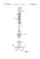
- FIG. 1is an exploded view illustrating an embodiment of a pusher-rotator assembly.
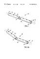
- FIG. 2is an isometric view illustrating an embodiment of a bend clip supporting a shaft in a straight position.
- FIG. 2Ais an isometric view illustrating an embodiment of a bend clip supporting a shaft in a bent position.
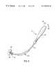
- FIG. 3is an isometric view illustrating an embodiment of a pusher-rotator assembly having a shaft held in a bent position by a bend clip.
- FIG. 4is an isometric view illustrating another embodiment of a bend clip supporting a shaft in a straight position.
- FIG. 4Ais an isometric view illustrating an embodiment of a bend clip supporting a shaft in a bent position.
- FIG. 4Bis an isometric view illustrating an embodiment of a bend clip having an adjustable shaft clip.
- FIG. 5is an isometric view illustrating a further embodiment of a bend clip supporting a shaft in a straight position.
- FIG. 5Ais an isometric view illustrating an embodiment of a bend clip supporting a shaft in a bent position.
- FIG. 5Bis an isometric view illustrating an embodiment of a bend clip having an adjustable shaft tab.
- a prosthetic heart valve holder 2is provided to be releasably coupled with a pusher-rotator assembly 4 for engaging and installing a heart valve prosthesis.
- Valve holder 2includes a valve coupling member 6 and a handle receiving member 8 .
- Pusher-rotator assembly 4includes a handle or grasping end 10 , a flexible medial shaft segment 12 , and a coupling assembly 14 attached to a terminal end of shaft 12 .
- Pusher-rotator 4is made from biocompatible, repeatedly sterilizable materials; preferably, grasping end 10 and coupling assembly 14 are made from polysulfone and shaft 12 is preferably made of a super elastic material sold under the name Nitinol. Grasping end 10 includes a ribbed or textured outer surface 11 . Also, grasping end 10 may be tapered or otherwise formed to provide a more ergonomic grasping area. Shaft 12 is generally annular in cross section and made from super flexible material which allow a surgeon to bend grasping end 10 relative to coupling assembly 14 during implantation. Consequently, the surgeon has greater flexibility in positioning the prosthetic valve while obtaining a desired view of the implantation area.
- a bend clip 20for use with pusher-rotator assembly 4 .
- a bend clip 20includes a first end 22 and a second end 24 .
- Bend clip 20is formed of a material such as stainless steel which is bendable to hold a fixed shape, FIG. 2 A.
- Bend clip 20FIGS. 2 and 2A, includes a bendable member in the form of an elongated tube 26 having a full-length aperture 28 extending from first end 22 to second end 24 for receiving shaft 12 .
- Tube 26has an outer annular wall 30 including a plurality of apertures 32 formed therein for facilitating the cleaning of bend clip 20 which may be mounted for axial movement on shaft 12 .
- a slot 34is formed in a portion of annular peripheral wall 30 to provide a relief for bending tube 26 .
- the bendable tube 26includes multiple contact points throughout aperture 28 for supporting flexible shaft 12 at spaced apart support points, such as at ends 22 and 24 , so that flexible shaft 12 is maintained rotatable and slidable while flexed within aperture 28 when tube 26 is holding a bend shape, see FIG. 3 .
- a prosthetic valve(not shown) may be positioned according to the bend of bend clip 20 so that rotation of grasping end 10 of pusher-rotator 4 , in directions indicated at R 1 and R 2 , will similarly rotate coupling assembly 14 via shaft 12 rotating within bend clip 20 .
- a bend clip 40in another embodiment, FIG. 4, includes a bendable member in the form of an elongated wire member 42 formed of a material such as stainless steel which is bendable to hold a fixed shape, FIG. 4 A.
- Wire member 42FIGS. 4 and 4A, includes a plurality of shaft clips 44 mounted thereon at a connection 45 .
- Each shaft clip 44includes a slot 46 formed therein for supporting shaft 12 , which is rotatably and axially movable in each slot 46 .
- Shaft clips 44may be fixedly mounted on wire member 42 or, alternatively, at least one of the shaft clips may be adjustably mounted on wire member 42 , see FIG. 4B, for movement in either of the directions designated D 1 and D 2 .
- the bendable wire member 42includes multiple contact points at each slot 46 for supporting shaft 12 at spaced apart support points, so that flexible shaft 12 is maintained rotatable while flexed within slots 46 when wire member 42 is holding a bend shape, see FIG. 4 A.
- a bend clip 50includes a bendable member in the form of an elongated bracket member 52 formed of a material such as stainless steel which is bendable to hold a fixed shape, FIG. 5 A.
- Bracket member 52FIGS. 5 and 5A, includes a plurality of shaft tabs 54 mounted thereon.
- Each shaft tab 54includes a slot 56 formed therein for supporting shaft 12 , which is rotatably and axially movable in each slot 56 .
- Shaft tabs 54may be fixedly mounted on bracket member 52 or, alternatively, at least one of the shaft clips may be adjustably mounted on bracket member 52 , see FIG. 5B, for movement in either of the directions designated D 1 and D 2 .
- the bendable bracket member 52includes multiple contact points at each slot 56 for supporting shaft 12 at spaced apart support points, so that flexible shaft 12 is maintained rotatable while flexed within slots 56 when bracket member 52 is holding a bend shape, see FIG. 5 A.
- a bend clipin operation includes an aperture for receiving shaft 12 , FIG. 2, or may be a clip-on attachment to shaft 12 via slotted shaft clips, FIG. 4, or slotted shaft tabs, FIG. 5 .
- the bend clipmay be bent to hold a flexed orientation in shaft 12 which closely approximates a bend angle desired to enable the surgeon to position a heart valve prosthesis adjacent a natural heart annulus, and then push and rotate the valve into position for attachment to the annulus.
- the shaft 12is supported by the bend clip for rotation in the flexed orientation.
- a bend clip for a flexible pusher-rotatorincluding a bendable member formed of a material which is bendable to hold a fixed shape.
- the bendable memberincludes multiple contact points for supporting a flexible shaft at spaced apart support points and maintaining the flexible shaft rotatable in a flexed orientation.
- FIG. 1Another embodiment provides a pusher-rotator for installing a heart valve prosthesis including a handle and a flexible shaft extending from the handle.
- a valve holderis attached to a terminal end of the shaft.
- a bendable memberis formed of a material which is bendable to hold a fixed shape. The bendable member includes multiple contact points for supporting the flexible shaft at spaced apart support points and maintaining the flexible shaft rotatable in a flexed orientation.
- a further embodimentprovides a method of maintaining a flexible pusher-rotator shaft in a flexed orientation.
- a bendable memberis formed of a material which is bendable to hold a fixed shape. Multiple, spaced apart support points are formed on the bendable member. The bendable member is then mounted on a flexible shaft so that the bendable member supports the flexible shaft at the spaced apart support points along the shaft for maintaining the shaft in a rotatable flexed orientation.
- the bend clipavoids the need for a two-point hand contact in order to bend and hold the flexible shaft of a pusher-rotator, and avoids a possible spring back of the shaft either inadvertently or when a valve holder at a terminal end of the shaft is disengaged from a mechanical valve being installed.
- the clipallows a surgeon to bend the device to a desired position.
- the clip devicethen maintains the bend configuration and allows the shaft to rotate freely.
- the clip devicemay be a permanent component of the pusher-rotator or may be removably attached as a clip-on component of the pusher-rotator.
- the permanent component configurationcomprises a tube with a plurality of holes formed therein for easy cleaning.
Landscapes
- Health & Medical Sciences (AREA)
- Cardiology (AREA)
- Oral & Maxillofacial Surgery (AREA)
- Transplantation (AREA)
- Engineering & Computer Science (AREA)
- Biomedical Technology (AREA)
- Heart & Thoracic Surgery (AREA)
- Vascular Medicine (AREA)
- Life Sciences & Earth Sciences (AREA)
- Animal Behavior & Ethology (AREA)
- General Health & Medical Sciences (AREA)
- Public Health (AREA)
- Veterinary Medicine (AREA)
- Prostheses (AREA)
Abstract
Description
Claims (25)
Priority Applications (1)
| Application Number | Priority Date | Filing Date | Title |
|---|---|---|---|
| US09/320,119US6200306B1 (en) | 1999-05-26 | 1999-05-26 | Bend clip for flexible rotator |
Applications Claiming Priority (1)
| Application Number | Priority Date | Filing Date | Title |
|---|---|---|---|
| US09/320,119US6200306B1 (en) | 1999-05-26 | 1999-05-26 | Bend clip for flexible rotator |
Publications (1)
| Publication Number | Publication Date |
|---|---|
| US6200306B1true US6200306B1 (en) | 2001-03-13 |
Family
ID=23244974
Family Applications (1)
| Application Number | Title | Priority Date | Filing Date |
|---|---|---|---|
| US09/320,119Expired - Fee RelatedUS6200306B1 (en) | 1999-05-26 | 1999-05-26 | Bend clip for flexible rotator |
Country Status (1)
| Country | Link |
|---|---|
| US (1) | US6200306B1 (en) |
Cited By (33)
| Publication number | Priority date | Publication date | Assignee | Title |
|---|---|---|---|---|
| US20030050645A1 (en)* | 2002-10-30 | 2003-03-13 | Parker Brad A. | Acetabular cup impactor |
| US20040210305A1 (en)* | 2002-07-16 | 2004-10-21 | Medtronic, Inc. | Suture locking assembly and method of use |
| US6814698B2 (en)* | 2001-10-05 | 2004-11-09 | Clarus Medical, Llc | Endoscope with flexible light guide having offset distal end |
| US20050228395A1 (en)* | 2004-03-05 | 2005-10-13 | Benoist Girard Sas | Prosthetic acetabular cup inserter |
| US20060015177A1 (en)* | 2004-07-19 | 2006-01-19 | St. Jude Medical, Inc. | Heart valve support and lid liner system and methods |
| US20060235508A1 (en)* | 2005-04-08 | 2006-10-19 | Ernest Lane | Two-Piece Prosthetic Valves with Snap-In Connection and Methods for Use |
| WO2007009117A1 (en)* | 2005-07-13 | 2007-01-18 | Arbor Surgical Technologies, Inc. | Two-piece percutaneous prosthetic heart valves and methods for making and using them |
| US20070156155A1 (en)* | 2006-01-03 | 2007-07-05 | Parker Brad A | Surgical cup impactor |
| US20080009953A1 (en)* | 2006-05-03 | 2008-01-10 | Benoist Girard Sas | Flanged prosthetic acetabular cup |
| US7717955B2 (en) | 2005-02-28 | 2010-05-18 | Medtronic, Inc. | Conformable prosthesis for implanting two-piece heart valves and methods for using them |
| US20100249935A1 (en)* | 2009-03-30 | 2010-09-30 | Slivka Michael A | Zero Profile Spinal Fusion Cage |
| USD628694S1 (en)* | 2009-05-18 | 2010-12-07 | Karl Storz Gmbh & Co. Kg | Medical device |
| US7967857B2 (en) | 2006-01-27 | 2011-06-28 | Medtronic, Inc. | Gasket with spring collar for prosthetic heart valves and methods for making and using them |
| US7972377B2 (en) | 2001-12-27 | 2011-07-05 | Medtronic, Inc. | Bioprosthetic heart valve |
| US7981153B2 (en) | 2002-12-20 | 2011-07-19 | Medtronic, Inc. | Biologically implantable prosthesis methods of using |
| US8021421B2 (en) | 2003-08-22 | 2011-09-20 | Medtronic, Inc. | Prosthesis heart valve fixturing device |
| US8083793B2 (en) | 2005-02-28 | 2011-12-27 | Medtronic, Inc. | Two piece heart valves including multiple lobe valves and methods for implanting them |
| US8211169B2 (en) | 2005-05-27 | 2012-07-03 | Medtronic, Inc. | Gasket with collar for prosthetic heart valves and methods for using them |
| WO2012129206A3 (en)* | 2011-03-22 | 2012-11-22 | Depuy Spine, Inc. | Novel implant inserter having a laterally-extending dovetail engagement feature |
| US8603161B2 (en) | 2003-10-08 | 2013-12-10 | Medtronic, Inc. | Attachment device and methods of using the same |
| US8821569B2 (en) | 2006-04-29 | 2014-09-02 | Medtronic, Inc. | Multiple component prosthetic heart valve assemblies and methods for delivering them |
| US9248028B2 (en) | 2011-09-16 | 2016-02-02 | DePuy Synthes Products, Inc. | Removable, bone-securing cover plate for intervertebral fusion cage |
| US9662225B2 (en) | 2012-03-06 | 2017-05-30 | DePuy Synthes Products, Inc. | Nubbed plate |
| US9687354B2 (en) | 2008-03-26 | 2017-06-27 | DePuy Synthes Products, Inc. | Posterior intervertebral disc inserter and expansion techniques |
| US10182921B2 (en) | 2012-11-09 | 2019-01-22 | DePuy Synthes Products, Inc. | Interbody device with opening to allow packing graft and other biologics |
| US10206787B2 (en) | 2006-12-22 | 2019-02-19 | Medos International Sarl | Composite vertebral spacers and instrument |
| US10335289B2 (en) | 2010-09-23 | 2019-07-02 | DePuy Synthes Products, Inc. | Stand alone intervertebral fusion device |
| US10500062B2 (en) | 2009-12-10 | 2019-12-10 | DePuy Synthes Products, Inc. | Bellows-like expandable interbody fusion cage |
| US10940016B2 (en) | 2017-07-05 | 2021-03-09 | Medos International Sarl | Expandable intervertebral fusion cage |
| US11471279B2 (en) | 2010-09-10 | 2022-10-18 | Edwards Lifesciences Corporation | Systems for rapidly deployable surgical heart valves |
| US11529241B2 (en) | 2010-09-23 | 2022-12-20 | DePuy Synthes Products, Inc. | Fusion cage with in-line single piece fixation |
| US11775613B2 (en) | 2010-09-10 | 2023-10-03 | Edwards Lifesciences Corporation | Methods of safely expanding prosthetic heart valves |
| US11931057B2 (en) | 2020-09-24 | 2024-03-19 | Arthrex, Inc. | Bendable handheld medical actuator |
Citations (8)
| Publication number | Priority date | Publication date | Assignee | Title |
|---|---|---|---|---|
| US5255668A (en)* | 1991-04-08 | 1993-10-26 | Kabushiki Kaisha Machida Seisakusho | Bending device |
| US5582607A (en) | 1994-09-09 | 1996-12-10 | Carbomedics, Inc. | Heart valve prosthesis rotator with bendable shaft and drive mechanism |
| US5749828A (en)* | 1995-12-22 | 1998-05-12 | Hewlett-Packard Company | Bending neck for use with invasive medical devices |
| US5772655A (en)* | 1995-05-19 | 1998-06-30 | Richard Wolf Gmbh | Medical instrument with a tilting distal end |
| US5873817A (en)* | 1997-05-12 | 1999-02-23 | Circon Corporation | Endoscope with resilient deflectable section |
| US5941818A (en)* | 1996-10-01 | 1999-08-24 | Vista Medical Technologies, Inc. | Endoscopic video camera with malleable support |
| US5976075A (en)* | 1997-12-15 | 1999-11-02 | University Of Massachusetts | Endoscope deployment apparatus |
| US6004329A (en)* | 1997-05-29 | 1999-12-21 | Baxter International Inc. | Shape-adjustable surgical implement handle |
- 1999
- 1999-05-26USUS09/320,119patent/US6200306B1/ennot_activeExpired - Fee Related
Patent Citations (8)
| Publication number | Priority date | Publication date | Assignee | Title |
|---|---|---|---|---|
| US5255668A (en)* | 1991-04-08 | 1993-10-26 | Kabushiki Kaisha Machida Seisakusho | Bending device |
| US5582607A (en) | 1994-09-09 | 1996-12-10 | Carbomedics, Inc. | Heart valve prosthesis rotator with bendable shaft and drive mechanism |
| US5772655A (en)* | 1995-05-19 | 1998-06-30 | Richard Wolf Gmbh | Medical instrument with a tilting distal end |
| US5749828A (en)* | 1995-12-22 | 1998-05-12 | Hewlett-Packard Company | Bending neck for use with invasive medical devices |
| US5941818A (en)* | 1996-10-01 | 1999-08-24 | Vista Medical Technologies, Inc. | Endoscopic video camera with malleable support |
| US5873817A (en)* | 1997-05-12 | 1999-02-23 | Circon Corporation | Endoscope with resilient deflectable section |
| US6004329A (en)* | 1997-05-29 | 1999-12-21 | Baxter International Inc. | Shape-adjustable surgical implement handle |
| US5976075A (en)* | 1997-12-15 | 1999-11-02 | University Of Massachusetts | Endoscope deployment apparatus |
Cited By (77)
| Publication number | Priority date | Publication date | Assignee | Title |
|---|---|---|---|---|
| US6814698B2 (en)* | 2001-10-05 | 2004-11-09 | Clarus Medical, Llc | Endoscope with flexible light guide having offset distal end |
| US7972377B2 (en) | 2001-12-27 | 2011-07-05 | Medtronic, Inc. | Bioprosthetic heart valve |
| US20040210305A1 (en)* | 2002-07-16 | 2004-10-21 | Medtronic, Inc. | Suture locking assembly and method of use |
| US7959674B2 (en) | 2002-07-16 | 2011-06-14 | Medtronic, Inc. | Suture locking assembly and method of use |
| US8349003B2 (en) | 2002-07-16 | 2013-01-08 | Medtronic, Inc. | Suture locking assembly and method of use |
| US7004946B2 (en)* | 2002-10-30 | 2006-02-28 | Symmetry Medical, Inc. | Acetabular cup impactor |
| US20030050645A1 (en)* | 2002-10-30 | 2003-03-13 | Parker Brad A. | Acetabular cup impactor |
| US7981153B2 (en) | 2002-12-20 | 2011-07-19 | Medtronic, Inc. | Biologically implantable prosthesis methods of using |
| US8623080B2 (en) | 2002-12-20 | 2014-01-07 | Medtronic, Inc. | Biologically implantable prosthesis and methods of using the same |
| US8551162B2 (en) | 2002-12-20 | 2013-10-08 | Medtronic, Inc. | Biologically implantable prosthesis |
| US10595991B2 (en) | 2002-12-20 | 2020-03-24 | Medtronic, Inc. | Heart valve assemblies |
| US9333078B2 (en) | 2002-12-20 | 2016-05-10 | Medtronic, Inc. | Heart valve assemblies |
| US8025695B2 (en) | 2002-12-20 | 2011-09-27 | Medtronic, Inc. | Biologically implantable heart valve system |
| US8460373B2 (en) | 2002-12-20 | 2013-06-11 | Medtronic, Inc. | Method for implanting a heart valve within an annulus of a patient |
| US8747463B2 (en) | 2003-08-22 | 2014-06-10 | Medtronic, Inc. | Methods of using a prosthesis fixturing device |
| US8021421B2 (en) | 2003-08-22 | 2011-09-20 | Medtronic, Inc. | Prosthesis heart valve fixturing device |
| US8603161B2 (en) | 2003-10-08 | 2013-12-10 | Medtronic, Inc. | Attachment device and methods of using the same |
| US7341593B2 (en) | 2004-03-05 | 2008-03-11 | Benoist Girard Sas | Prosthetic acetabular cup inserter |
| US20050228395A1 (en)* | 2004-03-05 | 2005-10-13 | Benoist Girard Sas | Prosthetic acetabular cup inserter |
| US7389874B2 (en) | 2004-07-19 | 2008-06-24 | St. Jude Medical, Inc. | Heart valve support and storing lid system and methods associated therewith |
| US20060015177A1 (en)* | 2004-07-19 | 2006-01-19 | St. Jude Medical, Inc. | Heart valve support and lid liner system and methods |
| US20100191327A1 (en)* | 2005-02-28 | 2010-07-29 | Medtronic, Inc. | Conformable prostheses for implanting two-piece heart valves and methods for using them |
| US10226331B2 (en) | 2005-02-28 | 2019-03-12 | Medtronic, Inc. | Conformable prostheses for implanting two-piece heart valves and methods for using them |
| US9402719B2 (en) | 2005-02-28 | 2016-08-02 | Medtronic, Inc. | Conformable prostheses for implanting two-piece heart valves and methods for using them |
| US7717955B2 (en) | 2005-02-28 | 2010-05-18 | Medtronic, Inc. | Conformable prosthesis for implanting two-piece heart valves and methods for using them |
| US8163014B2 (en) | 2005-02-28 | 2012-04-24 | Medtronic, Inc. | Conformable prostheses for implanting two-piece heart valves and methods for using them |
| US8083793B2 (en) | 2005-02-28 | 2011-12-27 | Medtronic, Inc. | Two piece heart valves including multiple lobe valves and methods for implanting them |
| US7951197B2 (en) | 2005-04-08 | 2011-05-31 | Medtronic, Inc. | Two-piece prosthetic valves with snap-in connection and methods for use |
| US20110190877A1 (en)* | 2005-04-08 | 2011-08-04 | Medtronic, Inc. | Two-Piece Prosthetic Valves with Snap-In Connection and Methods for Use |
| US7513909B2 (en) | 2005-04-08 | 2009-04-07 | Arbor Surgical Technologies, Inc. | Two-piece prosthetic valves with snap-in connection and methods for use |
| US8500802B2 (en) | 2005-04-08 | 2013-08-06 | Medtronic, Inc. | Two-piece prosthetic valves with snap-in connection and methods for use |
| US20060235508A1 (en)* | 2005-04-08 | 2006-10-19 | Ernest Lane | Two-Piece Prosthetic Valves with Snap-In Connection and Methods for Use |
| US8211169B2 (en) | 2005-05-27 | 2012-07-03 | Medtronic, Inc. | Gasket with collar for prosthetic heart valves and methods for using them |
| US20070016288A1 (en)* | 2005-07-13 | 2007-01-18 | Gurskis Donnell W | Two-piece percutaneous prosthetic heart valves and methods for making and using them |
| WO2007009117A1 (en)* | 2005-07-13 | 2007-01-18 | Arbor Surgical Technologies, Inc. | Two-piece percutaneous prosthetic heart valves and methods for making and using them |
| US20070156155A1 (en)* | 2006-01-03 | 2007-07-05 | Parker Brad A | Surgical cup impactor |
| US7967857B2 (en) | 2006-01-27 | 2011-06-28 | Medtronic, Inc. | Gasket with spring collar for prosthetic heart valves and methods for making and using them |
| US8821569B2 (en) | 2006-04-29 | 2014-09-02 | Medtronic, Inc. | Multiple component prosthetic heart valve assemblies and methods for delivering them |
| US20080009953A1 (en)* | 2006-05-03 | 2008-01-10 | Benoist Girard Sas | Flanged prosthetic acetabular cup |
| US11020237B2 (en) | 2006-12-22 | 2021-06-01 | Medos International Sarl | Composite vertebral spacers and instrument |
| US10206787B2 (en) | 2006-12-22 | 2019-02-19 | Medos International Sarl | Composite vertebral spacers and instrument |
| US9687354B2 (en) | 2008-03-26 | 2017-06-27 | DePuy Synthes Products, Inc. | Posterior intervertebral disc inserter and expansion techniques |
| US10206784B2 (en) | 2008-03-26 | 2019-02-19 | DePuy Synthes Products, Inc. | Posterior intervertebral disc inserter and expansion techniques |
| US9592129B2 (en) | 2009-03-30 | 2017-03-14 | DePuy Synthes Products, Inc. | Zero profile spinal fusion cage |
| US12097124B2 (en) | 2009-03-30 | 2024-09-24 | DePuy Synthes Products, Inc. | Zero profile spinal fusion cage |
| US11612491B2 (en) | 2009-03-30 | 2023-03-28 | DePuy Synthes Products, Inc. | Zero profile spinal fusion cage |
| US10624758B2 (en) | 2009-03-30 | 2020-04-21 | DePuy Synthes Products, Inc. | Zero profile spinal fusion cage |
| US9526620B2 (en) | 2009-03-30 | 2016-12-27 | DePuy Synthes Products, Inc. | Zero profile spinal fusion cage |
| US20100249935A1 (en)* | 2009-03-30 | 2010-09-30 | Slivka Michael A | Zero Profile Spinal Fusion Cage |
| USD628694S1 (en)* | 2009-05-18 | 2010-12-07 | Karl Storz Gmbh & Co. Kg | Medical device |
| US11607321B2 (en) | 2009-12-10 | 2023-03-21 | DePuy Synthes Products, Inc. | Bellows-like expandable interbody fusion cage |
| US10500062B2 (en) | 2009-12-10 | 2019-12-10 | DePuy Synthes Products, Inc. | Bellows-like expandable interbody fusion cage |
| US11775613B2 (en) | 2010-09-10 | 2023-10-03 | Edwards Lifesciences Corporation | Methods of safely expanding prosthetic heart valves |
| US11471279B2 (en) | 2010-09-10 | 2022-10-18 | Edwards Lifesciences Corporation | Systems for rapidly deployable surgical heart valves |
| EP3332741B1 (en)* | 2010-09-10 | 2024-08-28 | Edwards Lifesciences Corporation | Systems for rapidly deploying surgical heart valves |
| US12053377B2 (en) | 2010-09-10 | 2024-08-06 | Edwards Lifesciences Corporation | Methods for rapidly deployable surgical heart valves |
| US12164598B2 (en) | 2010-09-10 | 2024-12-10 | Edwards Lifesciences Corporation | Expandable prosthetic heart valve safety systems |
| US11529241B2 (en) | 2010-09-23 | 2022-12-20 | DePuy Synthes Products, Inc. | Fusion cage with in-line single piece fixation |
| US11678996B2 (en) | 2010-09-23 | 2023-06-20 | DePuy Synthes Products, Inc. | Stand alone intervertebral fusion device |
| US10369015B2 (en) | 2010-09-23 | 2019-08-06 | DePuy Synthes Products, Inc. | Implant inserter having a laterally-extending dovetail engagement feature |
| US12109127B2 (en) | 2010-09-23 | 2024-10-08 | DePuy Synthes Products, Inc. | Implant inserter having a laterally-extending dovetail engagement feature |
| US11382768B2 (en) | 2010-09-23 | 2022-07-12 | DePuy Synthes Products, Inc. | Implant inserter having a laterally-extending dovetail engagement feature |
| US10335289B2 (en) | 2010-09-23 | 2019-07-02 | DePuy Synthes Products, Inc. | Stand alone intervertebral fusion device |
| WO2012129206A3 (en)* | 2011-03-22 | 2012-11-22 | Depuy Spine, Inc. | Novel implant inserter having a laterally-extending dovetail engagement feature |
| US10159582B2 (en) | 2011-09-16 | 2018-12-25 | DePuy Synthes Products, Inc. | Removable, bone-securing cover plate for intervertebral fusion cage |
| US9248028B2 (en) | 2011-09-16 | 2016-02-02 | DePuy Synthes Products, Inc. | Removable, bone-securing cover plate for intervertebral fusion cage |
| US10813773B2 (en) | 2011-09-16 | 2020-10-27 | DePuy Synthes Products, Inc. | Removable, bone-securing cover plate for intervertebral fusion cage |
| US10327915B2 (en) | 2012-03-06 | 2019-06-25 | DePuy Synthes Products, Inc. | Nubbed plate |
| US11844702B2 (en) | 2012-03-06 | 2023-12-19 | DePuy Synthes Products, Inc. | Nubbed plate |
| US9872781B2 (en) | 2012-03-06 | 2018-01-23 | DePuy Synthes Products, Inc. | Nubbed plate |
| US9668877B2 (en) | 2012-03-06 | 2017-06-06 | DePuy Synthes Products, Inc. | Nubbed plate |
| US9662225B2 (en) | 2012-03-06 | 2017-05-30 | DePuy Synthes Products, Inc. | Nubbed plate |
| US11071634B2 (en) | 2012-03-06 | 2021-07-27 | DePuy Synthes Products, Inc. | Nubbed plate |
| US10182921B2 (en) | 2012-11-09 | 2019-01-22 | DePuy Synthes Products, Inc. | Interbody device with opening to allow packing graft and other biologics |
| US11497616B2 (en) | 2012-11-09 | 2022-11-15 | DePuy Synthes Products, Inc. | Interbody device with opening to allow packing graft and other biologics |
| US10940016B2 (en) | 2017-07-05 | 2021-03-09 | Medos International Sarl | Expandable intervertebral fusion cage |
| US11931057B2 (en) | 2020-09-24 | 2024-03-19 | Arthrex, Inc. | Bendable handheld medical actuator |
Similar Documents
| Publication | Publication Date | Title |
|---|---|---|
| US6200306B1 (en) | Bend clip for flexible rotator | |
| US6613085B1 (en) | Prosthetic heart valve rotator tool | |
| US6231601B1 (en) | Method of surgery including adjusting the shape of an implement handle | |
| EP1269922B1 (en) | Articulated and lockable suture retaining retractor ring | |
| US6004329A (en) | Shape-adjustable surgical implement handle | |
| EP3691541B1 (en) | Bendable cardiac surgery instruments | |
| US5984867A (en) | Surgical retractor and method of retracting | |
| EP2670356B1 (en) | Adjustable prosthetic anatomical device holder and handle for the implantation of an annuloplasty ring | |
| EP2520250B1 (en) | Medical device for a cardiac valve implant | |
| US8025649B2 (en) | Method for use of attachment device and system for corneal irrigating cannula | |
| EP0798985B1 (en) | Separable economically partially disposable flexible biopsy forceps | |
| GB2146900A (en) | Surgical clip and forceps for clamping the same | |
| WO2007092682A1 (en) | Surgical robotic helping hand system | |
| US10918480B2 (en) | Medical device for a cardiac valve implant, and a method of manufacturing the medical device | |
| US11116597B2 (en) | Biopsy device support or holder and method of use | |
| US6358240B1 (en) | Low profile flexible pusher rotator | |
| US5788689A (en) | Prosthetic heart valve rotator tool | |
| WO2003030741A1 (en) | Ratcheting mechanism for endoscopic instruments | |
| JP2004290569A (en) | Medical treatment processing device | |
| US11931057B2 (en) | Bendable handheld medical actuator | |
| US20250195207A1 (en) | System for attaching intraocular devices to iris tissue |
Legal Events
| Date | Code | Title | Description |
|---|---|---|---|
| AS | Assignment | Owner name:SULZER CARBOMEDICS INC., TEXAS Free format text:ASSIGNMENT OF ASSIGNORS INTEREST;ASSIGNORS:KLOSTERMEYER, TAMMI E.;HEINRICH, CHRISTOPHER;REEL/FRAME:010015/0096 Effective date:19990525 | |
| AS | Assignment | Owner name:SULZER CARBOMEDICS INC., TEXAS Free format text:RELEASE OF SECURITY INTEREST;ASSIGNORS:UBS AG, STAMFORD BRANCH (ON ITS OWN BEHALF AND AS A SECURITY AGENT);CENTERPULSE USA HOLDING CO., A CORP. OF DELAWARE;CENTERPULSE USA INC., A CORP. OF DELAWARE;AND OTHERS;REEL/FRAME:013496/0824 Effective date:20030121 | |
| REMI | Maintenance fee reminder mailed | ||
| LAPS | Lapse for failure to pay maintenance fees | ||
| LAPS | Lapse for failure to pay maintenance fees | Free format text:PATENT EXPIRED FOR FAILURE TO PAY MAINTENANCE FEES (ORIGINAL EVENT CODE: EXP.); ENTITY STATUS OF PATENT OWNER: LARGE ENTITY | |
| STCH | Information on status: patent discontinuation | Free format text:PATENT EXPIRED DUE TO NONPAYMENT OF MAINTENANCE FEES UNDER 37 CFR 1.362 | |
| FP | Lapsed due to failure to pay maintenance fee | Effective date:20050313 | |
| AS | Assignment | Owner name:CORCYM S.R.L., ITALY Free format text:ASSIGNMENT OF ASSIGNORS INTEREST;ASSIGNOR:LIVANVOA USA, INC.;REEL/FRAME:056544/0121 Effective date:20210601 |