US6199956B1 - Round-shank bit for a coal cutting machine - Google Patents
Round-shank bit for a coal cutting machineDownload PDFInfo
- Publication number
- US6199956B1 US6199956B1US09/238,999US23899999AUS6199956B1US 6199956 B1US6199956 B1US 6199956B1US 23899999 AUS23899999 AUS 23899999AUS 6199956 B1US6199956 B1US 6199956B1
- Authority
- US
- United States
- Prior art keywords
- bit
- area
- shank
- tip
- base element
- Prior art date
- Legal status (The legal status is an assumption and is not a legal conclusion. Google has not performed a legal analysis and makes no representation as to the accuracy of the status listed.)
- Expired - Lifetime
Links
Images
Classifications
- E—FIXED CONSTRUCTIONS
- E21—EARTH OR ROCK DRILLING; MINING
- E21C—MINING OR QUARRYING
- E21C35/00—Details of, or accessories for, machines for slitting or completely freeing the mineral from the seam, not provided for in groups E21C25/00 - E21C33/00, E21C37/00 or E21C39/00
- E21C35/18—Mining picks; Holders therefor
- E21C35/183—Mining picks; Holders therefor with inserts or layers of wear-resisting material
- B—PERFORMING OPERATIONS; TRANSPORTING
- B28—WORKING CEMENT, CLAY, OR STONE
- B28D—WORKING STONE OR STONE-LIKE MATERIALS
- B28D1/00—Working stone or stone-like materials, e.g. brick, concrete or glass, not provided for elsewhere; Machines, devices, tools therefor
- B28D1/18—Working stone or stone-like materials, e.g. brick, concrete or glass, not provided for elsewhere; Machines, devices, tools therefor by milling, e.g. channelling by means of milling tools
- B28D1/186—Tools therefor, e.g. having exchangeable cutter bits
- B28D1/188—Tools therefor, e.g. having exchangeable cutter bits with exchangeable cutter bits or cutter segments
- E—FIXED CONSTRUCTIONS
- E21—EARTH OR ROCK DRILLING; MINING
- E21C—MINING OR QUARRYING
- E21C35/00—Details of, or accessories for, machines for slitting or completely freeing the mineral from the seam, not provided for in groups E21C25/00 - E21C33/00, E21C37/00 or E21C39/00
- E21C35/18—Mining picks; Holders therefor
- E21C35/183—Mining picks; Holders therefor with inserts or layers of wear-resisting material
- E21C35/1837—Mining picks; Holders therefor with inserts or layers of wear-resisting material characterised by the shape
- E—FIXED CONSTRUCTIONS
- E21—EARTH OR ROCK DRILLING; MINING
- E21C—MINING OR QUARRYING
- E21C35/00—Details of, or accessories for, machines for slitting or completely freeing the mineral from the seam, not provided for in groups E21C25/00 - E21C33/00, E21C37/00 or E21C39/00
- E21C35/18—Mining picks; Holders therefor
- E21C35/188—Mining picks; Holders therefor characterised by adaptations to use an extraction tool
Definitions
- This inventionrelates to a round-shank bit for a coal cutting machine or the like, having a bit head and a bit shank, wherein the bit head has a bit tip, maintained by a base element in a receptacle of the bit head, and starting at the base element, the bit tip tapers in a direction toward a free end of the bit tip, wherein the base element forms a maximum diameter of the bit tip, and the bit tip has recesses on an outer contour.
- Such round-shank bitsare installed in bit holders, which are fastened to a rotating body.
- the bit tipsengage and penetrate the material to be removed, for example, rocks, coal, road covering and the like.
- the bit tipwears during this engagement.
- the bit shank of the round-shank bitis rotatably held in a bit holder.
- the bit tiphas recesses on an outer circumference, which extend in a longitudinal direction of the round-shank bit. In this case the recesses extend from the bit tip as far as the bit head, where the recesses end continuously.
- the round-shank bitfurthermore has a tendency for blockage when the lands formed between the recesses are worn out, but when the wear limit is not quite reached.
- This objectis attained with a base element having recesses on its outer circumference, which constitutes the maximum diameter.
- the outer contour of the bit tip on a side facing the bit headhas alternatingly recesses and intermediate elements located between the recesses. This results, for example, in a star-shaped or a tooth-shaped outer contour of the base element.
- the removed materialis taken away in a definite manner via the recesses toward the bit head.
- an intentional wear of the bit headis caused, which carries the recesses on in the form of wash-outs in the bit head.
- the removed materialintroduces a force component in a circumferential direction into the round-shank bit via the recesses and wash-outs.
- the rotating property of the round-shank bitis assured up to the wear limit.
- the design of the bit tip in accordance with this inventionalso utilizes knowledge that in a not yet worn out state the bit tip must have sufficient support on the bit head in order to be able to dependably deflect occurring transverse forces. During increasing wear, however, lesser bending stresses are transmitted via the transition between the bit tip and the bit head because of the wear-induced shortening of the bit tip. At the beginning of use, the intermediate elements between the recesses assure sufficient support of the bit tip.
- the recessesare uniformly cut into the base element up to an interior graduated circle extended around the center longitudinal axis of the bit tip.
- the bit tipis designed star-shaped on its outer contour defined by the base element. A uniform rotational behavior can also be assured because of the uniform erosion of the recesses.
- the recessesterminate continuously and directly in the tapered area of the bit tip adjoining the base element, a precise flow of the removed material becomes possible. In order not to cause an unnecessary weakening of the bit tip and rapid wear, the recesses should terminate directly adjoining the base element.
- a preferred embodimentis distinguished because the receptacle in the bit head is enclosed by a collar around the circumference, and the recesses extend in the axial direction of the bit tip past the collar into the contact surface of the bit tip on the bit head.
- the recessesdo not contact or only partially contact the removed material at initial use of the tool. In this state the round-shank bit is capable of sufficient rotation because of its geometry alone. When used, the collar is ground off and the recesses are increasingly exposed. Thus, the support of the rotation in accordance with the invention then becomes effective.
- the area of a free end of the bit tiphas a conical first area, which makes a transition into a second cylindrical transition area, and following the cylindrical transition area, the bit tip extends in a direction toward the base element over a truncated cone-shaped or concavely tapered area.
- a round-shank bit of this typehas very good cutting properties and a long service life.
- bit tipLong service life can also be achieved if in the region of the free end the bit tip has a conical or approximately conical area, and if a second area in the shape of a truncated cone or nearly truncated cone adjoins the first area, having a cone opening angle less than the cone opening angle of the first area.
- the second areatransitions into the base element via a further, third area in the shape of a truncated cone or nearly truncated cone, wherein the cone opening angle of the third area is greater than the cone opening angle of the second area.
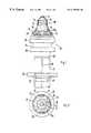
- FIG. 1is a partial sectional side view of a round-shank bit
- FIG. 2is a top view of the round-shank bit shown in FIG. 1;
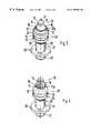
- FIG. 3is a perspective view of the round-shank bit shown in FIGS. 1 and 2;
- FIG. 4is a perspective view of the round-shank bit shown in FIG. 3, but in the worn out state.
- a round-shank bitis shown in a partial sectional side view in FIG. 1 .
- the round-shank bitcomprises a bit tip 10 , a bit head 20 and a bit shank 26 .
- a clamping sleeve 31is drawn on the cylindrical bit shank 26 .
- Tabs 33are stamped out from the clamping sleeve 31 and are bent off in a direction toward the bit shank 26 .
- the tabs 33engage a circumferential groove 27 of the bit shank 26 and prevent the clamping sleeve 31 from being pulled off the bit shank 26 .
- a bore in a wear-protection diskis pushed on the clamping sleeve 31 in the area of the tabs 33 .
- the diameter of the boreis of such a size that the clamping sleeve 31 is maintained in a prestressed state.
- the round-shank bitWith the bit shank 26 , the round-shank bit can be inserted into a bore of the bit holder.
- the diameter of the boreis of such a size that the clamping sleeve 31 of the round-shank bit can be inserted with only a relatively small force.
- the insertion of the bit shank 26can have an increased force.
- the wear-protection disk 30is displaced in the direction toward the bit head 20 until there is no contact with the clamping sleeve 31 .
- the clamping sleeve 31then expands, and the longitudinal slit 32 is widened.
- the clamping sleeve 31is then braced in the bore of the bit holder.
- the wear-protection disk 30rests on the surface of the bit holder 26 and protects against wear created by rotation of the round-shank bit.
- the bit head 20adjoins the bit shank 26 by means of a cylindrical element 25 .
- the cylindrical element 25transitions into a constriction 24 , which in turn terminates in a further cylindrical element 23 .
- a toolcan be inserted into the constriction, by means of which the round-shank bit can then be pulled out of the bore of the bit holder, when worn out.
- the bit head 20On an end remote from the shank bit, the bit head 20 has a receptacle 21 bordered by a circumferential collar 22 .
- the receptacle 21has a flat contact surface, on which the bit tip 10 is placed and soldered.
- the bit tip 10is designed as a hard metal insert.
- the bit tip 10has a base element 16 , which is inserted into the receptacle 21 . Adjoining the base element 16 , the bit tip 10 transitions via a tapered area 15 into a cylindrical transition area.
- the tapered area 15is designed concave, wherein the bit tip 10 widens, starting at the cylindrical transition area 13 , in the direction toward the base element 16 . Accordingly, the base element 16 has a maximum diameter of the dynamically balanced bit tip 10 .
- Between tapered area 15 and cylindrical transition area 13is a truncated conical area 14 of right circular cone shape.
- the bit tip 10has a first area 12 in the shape of a truncated cone on the free end, which is closed off by a rounded portion 11 .
- Recesses 17are cut out of the exterior circumference of the bit tip 10 in the transition area between the base element 16 and the tapered area 15 .
- the recesses 17are cut into the base element 16 in a pocket shape and terminate continuously in the tapered area 15 .
- Land-shaped intermediate elements 17 aare formed between the individual recesses 17 , by means of which the bit tip 10 is supported on the contact surface of the receptacle 21 .
- FIG. 2shows the round-shank bit in a top view. Together with the intermediate elements 17 a , the recesses 17 provide the bit tip 10 with a star-shaped geometry.
- the round-shank bit represented in FIGS. 1 and 2is shown in a perspective view in FIG. 3 . As can be seen from this representation, the recesses 17 form transition areas into the bit head 20 .
- the material to be removedis cut off by the bit tip 21 .
- the removed materialthen flows past the tapered area 15 toward the recesses 17 , and in the process grinds past the bit head 20 .
- the recesses 17continue in the bit head 20 in the form of wash-outs 18 , as shown in FIG. 4 . Since the round-shank bit rotates when in use, the wash-outs 18 are created in a twist-like manner around the center longitudinal axis of the round-shank bit.
- the recesses 17 , and later on the wash-outs 18make it possible for the removed material to introduce a force in the circumferential direction of the bit head 20 . By means of this the rotating movement of the round-shank bit is assisted, for optimizing wear.
- the cutting-friendliness of the round-shank bitis also assisted by the recesses 17 , in accordance with this invention.
- the wash-outs 18reduce the exterior cross section of the bit head 20 in a predeterminable manner.
- the intermediate elements 17 aoffer a sufficient support width on the contact surface of the receptacle 21 , so that the occurring transverse forces can be dependably absorbed. If, because of wear, the bit tip 10 experiences a shortening in the axial direction when used, the support width can then also be increasingly reduced.
- This inventioncompensates for continuous wear of the intermediate elements 17 a after the wash-outs 18 are ground. Because of this simple measure the slim, cutting-friendly geometry of the round-shank bit 10 is always maintained over the entire length of the operation.
Landscapes
- Engineering & Computer Science (AREA)
- Mining & Mineral Resources (AREA)
- Mechanical Engineering (AREA)
- Life Sciences & Earth Sciences (AREA)
- General Life Sciences & Earth Sciences (AREA)
- Geochemistry & Mineralogy (AREA)
- Geology (AREA)
- Drilling And Exploitation, And Mining Machines And Methods (AREA)
- Percussive Tools And Related Accessories (AREA)
Abstract
Description
Claims (10)
Applications Claiming Priority (2)
| Application Number | Priority Date | Filing Date | Title |
|---|---|---|---|
| DE19803166 | 1998-01-28 | ||
| DE19803166ADE19803166C2 (en) | 1998-01-28 | 1998-01-28 | Round shank chisels for a cutting machine or the like |
Publications (1)
| Publication Number | Publication Date |
|---|---|
| US6199956B1true US6199956B1 (en) | 2001-03-13 |
Family
ID=7855872
Family Applications (1)
| Application Number | Title | Priority Date | Filing Date |
|---|---|---|---|
| US09/238,999Expired - LifetimeUS6199956B1 (en) | 1998-01-28 | 1999-01-27 | Round-shank bit for a coal cutting machine |
Country Status (2)
| Country | Link |
|---|---|
| US (1) | US6199956B1 (en) |
| DE (1) | DE19803166C2 (en) |
Cited By (107)
| Publication number | Priority date | Publication date | Assignee | Title |
|---|---|---|---|---|
| US6375272B1 (en)* | 2000-03-24 | 2002-04-23 | Kennametal Inc. | Rotatable cutting tool insert |
| US6378952B1 (en)* | 1999-05-14 | 2002-04-30 | Betek Bergbau-Und Hartmetalltechnik Karl-Heinz Simon Gmbh & Co., Kg | Tool for a coal cutting, mining or road cutting machine |
| US6554369B2 (en) | 2001-07-12 | 2003-04-29 | The Sollami Company | Cutting tool with hardened insert |
| US20040004389A1 (en)* | 2002-06-14 | 2004-01-08 | Latham Winchester E. | Replacable wear surface for bit support |
| US20040026132A1 (en)* | 2002-08-10 | 2004-02-12 | Hall David R. | Pick for disintegrating natural and man-made materials |
| US6692083B2 (en) | 2002-06-14 | 2004-02-17 | Keystone Engineering & Manufacturing Corporation | Replaceable wear surface for bit support |
| USD554162S1 (en) | 2007-03-27 | 2007-10-30 | Hall David R | Diamond enhanced cutting element |
| US20070257545A1 (en)* | 2006-05-08 | 2007-11-08 | Sandvik Intelectual Property Ab | Cutting tool and method of assembling the cutting tool |
| US20070290545A1 (en)* | 2006-06-16 | 2007-12-20 | Hall David R | An Attack Tool for Degrading Materials |
| US20070290546A1 (en)* | 2006-06-16 | 2007-12-20 | Hall David R | A Wear Resistant Tool |
| US7320505B1 (en) | 2006-08-11 | 2008-01-22 | Hall David R | Attack tool |
| US20080036281A1 (en)* | 2006-08-11 | 2008-02-14 | Hall David R | Hollow Pick Shank |
| US20080036272A1 (en)* | 2006-08-11 | 2008-02-14 | Hall David R | Washer for a degradation assembly |
| US20080036279A1 (en)* | 2006-08-11 | 2008-02-14 | Hall David R | Holder for a degradation assembly |
| US20080036283A1 (en)* | 2006-08-11 | 2008-02-14 | Hall David R | Attack Tool |
| US20080035383A1 (en)* | 2006-08-11 | 2008-02-14 | Hall David R | Non-rotating Pick with a Pressed in Carbide Segment |
| US20080035381A1 (en)* | 2006-08-11 | 2008-02-14 | Hall David R | Lubricating drum |
| US20080035386A1 (en)* | 2006-08-11 | 2008-02-14 | Hall David R | Pick Assembly |
| US20080036176A1 (en)* | 2006-08-09 | 2008-02-14 | Schuettenberg Donald W | Front Tow Extended Saddle |
| US20080036274A1 (en)* | 2006-08-11 | 2008-02-14 | Hall David R | Sleeve in a Degradation Assembly |
| US20080036282A1 (en)* | 2006-08-11 | 2008-02-14 | Hall David R | Attack Tool |
| US20080036275A1 (en)* | 2006-08-11 | 2008-02-14 | Hall David R | Retainer Sleeve in a Degradation Assembly |
| US20080036270A1 (en)* | 2006-08-11 | 2008-02-14 | Hall David R | Pick with a Bearing |
| US20080036273A1 (en)* | 2006-08-11 | 2008-02-14 | Hall David R | Washer for a Degradation Assembly |
| US20080035380A1 (en)* | 2006-08-11 | 2008-02-14 | Hall David R | Pointed Diamond Working Ends on a Shear Bit |
| US20080035387A1 (en)* | 2006-08-11 | 2008-02-14 | Hall David R | Downhole Drill Bit |
| US20080048484A1 (en)* | 2006-08-11 | 2008-02-28 | Hall David R | Shank for an Attack Tool |
| US20080067859A1 (en)* | 2006-08-11 | 2008-03-20 | Hall David R | Shank Assembly |
| USD566137S1 (en)* | 2006-08-11 | 2008-04-08 | Hall David R | Pick bolster |
| US20080088172A1 (en)* | 2006-08-11 | 2008-04-17 | Hall David R | Holder Assembly |
| US20080099251A1 (en)* | 2006-10-26 | 2008-05-01 | Hall David R | High impact resistant tool |
| US20080115977A1 (en)* | 2006-08-11 | 2008-05-22 | Hall David R | Impact Tool |
| US7380888B2 (en)* | 2001-04-19 | 2008-06-03 | Kennametal Inc. | Rotatable cutting tool having retainer with dimples |
| US20080129104A1 (en)* | 2006-08-11 | 2008-06-05 | Hall David R | Impact Tool |
| US7390066B2 (en) | 2006-08-11 | 2008-06-24 | Hall David R | Method for providing a degradation drum |
| US7396086B1 (en) | 2007-03-15 | 2008-07-08 | Hall David R | Press-fit pick |
| USD572735S1 (en) | 2006-05-02 | 2008-07-08 | Betek Bergbau- Und Hartmetalltechnik | Chisel-tip for a cutter-bit |
| US20080185468A1 (en)* | 2006-08-11 | 2008-08-07 | Hall David R | Degradation insert with overhang |
| US20080197691A1 (en)* | 2006-08-11 | 2008-08-21 | Hall David R | Locking fixture for a degradation assembly |
| US20080211290A1 (en)* | 2006-08-11 | 2008-09-04 | Hall David R | Tapered Bore in a Pick |
| US20080246329A1 (en)* | 2006-08-11 | 2008-10-09 | Hall David R | Retention System |
| US20080250724A1 (en)* | 2007-04-12 | 2008-10-16 | Hall David R | High Impact Shearing Element |
| US20080264697A1 (en)* | 2006-08-11 | 2008-10-30 | Hall David R | Retention for an Insert |
| US20080284235A1 (en)* | 2007-05-15 | 2008-11-20 | Hall David R | Spring Loaded Pick |
| US20080284234A1 (en)* | 2007-05-14 | 2008-11-20 | Hall David R | Pick with a Reentrant |
| USD581952S1 (en) | 2006-08-11 | 2008-12-02 | Hall David R | Pick |
| US20080309147A1 (en)* | 2006-08-11 | 2008-12-18 | Hall David R | Shield of a Degradation Assembly |
| US20080309149A1 (en)* | 2006-08-11 | 2008-12-18 | Hall David R | Braze Thickness Control |
| US20090066149A1 (en)* | 2007-09-07 | 2009-03-12 | Hall David R | Pick with Carbide Cap |
| US20090133938A1 (en)* | 2006-08-11 | 2009-05-28 | Hall David R | Thermally Stable Pointed Diamond with Increased Impact Resistance |
| US20090160238A1 (en)* | 2007-12-21 | 2009-06-25 | Hall David R | Retention for Holder Shank |
| US20090162159A1 (en)* | 2005-10-27 | 2009-06-25 | Karl Kammerer | Circular-Shank Tool Comprising a Tool Holder |
| US20090160237A1 (en)* | 2005-10-27 | 2009-06-25 | Karl Kammerer | Circular-Shank Tool Comprising a Tool Holder |
| US7568770B2 (en) | 2006-06-16 | 2009-08-04 | Hall David R | Superhard composite material bonded to a steel body |
| US20090200855A1 (en)* | 2006-08-11 | 2009-08-13 | Hall David R | Manually Rotatable Tool |
| US20090200857A1 (en)* | 2006-08-11 | 2009-08-13 | Hall David R | Manually Rotatable Tool |
| US20090267403A1 (en)* | 2006-08-11 | 2009-10-29 | Hall David R | Resilient Pick Shank |
| US7628233B1 (en) | 2008-07-23 | 2009-12-08 | Hall David R | Carbide bolster |
| US7637574B2 (en) | 2006-08-11 | 2009-12-29 | Hall David R | Pick assembly |
| US20100000794A1 (en)* | 2005-11-21 | 2010-01-07 | Hall David R | Lead the Bit Rotary Steerable Tool |
| US7648210B2 (en) | 2006-08-11 | 2010-01-19 | Hall David R | Pick with an interlocked bolster |
| US20100018776A1 (en)* | 2008-07-28 | 2010-01-28 | Keller Donald E | Cutting bit for mining and excavating tools |
| US20100054875A1 (en)* | 2006-08-11 | 2010-03-04 | Hall David R | Test Fixture that Positions a Cutting Element at a Positive Rake Angle |
| US20100065332A1 (en)* | 2006-08-11 | 2010-03-18 | Hall David R | Method for Drilling with a Fixed Bladed Bit |
| US7740414B2 (en) | 2005-03-01 | 2010-06-22 | Hall David R | Milling apparatus for a paved surface |
| USD620510S1 (en)* | 2006-03-23 | 2010-07-27 | Schlumberger Technology Corporation | Drill bit |
| US20100264721A1 (en)* | 2009-04-16 | 2010-10-21 | Hall David R | Seal with Rigid Element for Degradation Assembly |
| US20100263939A1 (en)* | 2006-10-26 | 2010-10-21 | Hall David R | High Impact Resistant Tool with an Apex Width between a First and Second Transitions |
| US20100275425A1 (en)* | 2009-04-29 | 2010-11-04 | Hall David R | Drill Bit Cutter Pocket Restitution |
| US7832808B2 (en) | 2007-10-30 | 2010-11-16 | Hall David R | Tool holder sleeve |
| USD627808S1 (en) | 2009-12-23 | 2010-11-23 | Betek Bergbau- Und Hartmetalltechnik Karl-Heinz Simon Gmbh & Co. Kg | Chisel bit |
| US20100295360A1 (en)* | 2007-10-29 | 2010-11-25 | Betek Bergbau-Und Hartmetall-Technik Karl-Heinz Si | Shank Chisel |
| US20110013983A1 (en)* | 2006-12-01 | 2011-01-20 | Hall David R | End of a Moldboard Positioned Proximate a Milling Drum |
| US20110018333A1 (en)* | 2006-12-01 | 2011-01-27 | Hall David R | Plurality of Liquid Jet Nozzles and a Blower Mechanism that are Directed into a Milling Chamber |
| US20110091276A1 (en)* | 2006-12-01 | 2011-04-21 | Hall David R | Heated Liquid Nozzles Incorporated into a Moldboard |
| US20110175430A1 (en)* | 2010-01-20 | 2011-07-21 | Ernst Heiderich | Pick tool and method for making same |
| US8061457B2 (en) | 2009-02-17 | 2011-11-22 | Schlumberger Technology Corporation | Chamfered pointed enhanced diamond insert |
| CN101787887B (en)* | 2010-01-12 | 2012-01-11 | 太原理工大学 | Pick having bimetal structure and preparation method thereof |
| WO2012075671A1 (en)* | 2010-12-06 | 2012-06-14 | Li Shiqing | High efficiency crack-resistant reduced-dusting milling cutter |
| US8250786B2 (en) | 2010-06-30 | 2012-08-28 | Hall David R | Measuring mechanism in a bore hole of a pointed cutting element |
| US8262168B2 (en) | 2010-09-22 | 2012-09-11 | Hall David R | Multiple milling drums secured to the underside of a single milling machine |
| US8360174B2 (en) | 2006-03-23 | 2013-01-29 | Schlumberger Technology Corporation | Lead the bit rotary steerable tool |
| US8414085B2 (en) | 2006-08-11 | 2013-04-09 | Schlumberger Technology Corporation | Shank assembly with a tensioned element |
| US8449039B2 (en) | 2010-08-16 | 2013-05-28 | David R. Hall | Pick assembly with integrated piston |
| US8499857B2 (en) | 2007-09-06 | 2013-08-06 | Schlumberger Technology Corporation | Downhole jack assembly sensor |
| US8540037B2 (en) | 2008-04-30 | 2013-09-24 | Schlumberger Technology Corporation | Layered polycrystalline diamond |
| US8567532B2 (en) | 2006-08-11 | 2013-10-29 | Schlumberger Technology Corporation | Cutting element attached to downhole fixed bladed bit at a positive rake angle |
| US8646848B2 (en) | 2007-12-21 | 2014-02-11 | David R. Hall | Resilient connection between a pick shank and block |
| US8668275B2 (en) | 2011-07-06 | 2014-03-11 | David R. Hall | Pick assembly with a contiguous spinal region |
| US8728382B2 (en) | 2011-03-29 | 2014-05-20 | David R. Hall | Forming a polycrystalline ceramic in multiple sintering phases |
| US9051795B2 (en) | 2006-08-11 | 2015-06-09 | Schlumberger Technology Corporation | Downhole drill bit |
| US9068410B2 (en) | 2006-10-26 | 2015-06-30 | Schlumberger Technology Corporation | Dense diamond body |
| US9074472B2 (en) | 2009-10-19 | 2015-07-07 | Betek Gmbh & Co. Kg | Bit, in particular a round shaft bit |
| USD735255S1 (en)* | 2013-12-24 | 2015-07-28 | The Yankee Candle Company, Inc. | Heater dish and wax cup for electric wax melting system |
| USD735786S1 (en)* | 2013-07-11 | 2015-08-04 | Sievert Ab | Blowtorch |
| US9320669B2 (en) | 2005-08-12 | 2016-04-26 | Bonutti Research, Inc. | Range of motion system |
| USD772315S1 (en)* | 2013-04-11 | 2016-11-22 | Betek Gmbh & Co. Kg | Chisel |
| WO2017142465A1 (en)* | 2016-02-19 | 2017-08-24 | Atlas Copco Secoroc Ab | Cutting tool for coal mining, mechanical processing of rocks, use during rotary drilling or working asphalt, concrete or like material, provided with longitudinally extending grooves |
| US9915102B2 (en) | 2006-08-11 | 2018-03-13 | Schlumberger Technology Corporation | Pointed working ends on a bit |
| USD818507S1 (en) | 2017-02-28 | 2018-05-22 | Kennametal Inc | Replaceable tip for a rotatable cutting tool |
| USD863386S1 (en) | 2018-06-06 | 2019-10-15 | Kennametal Inc. | Ribbed cutting insert |
| US10456314B2 (en) | 2005-10-28 | 2019-10-29 | Bonutti Research, Inc. | Range of motion device |
| CN110469274A (en)* | 2019-08-26 | 2019-11-19 | 山东源运通矿山装备科技有限公司 | Coal drill bit |
| CN112105798A (en)* | 2018-04-17 | 2020-12-18 | 必泰克有限两合公司 | Milling chisel |
| USD915591S1 (en)* | 2019-01-25 | 2021-04-06 | Beijing Smtp Technology Co., Ltd. | Ultrasonic cutter head for medical purpose |
| USD918973S1 (en) | 2018-08-01 | 2021-05-11 | Betek Gmbh & Co. Kg | Milling tool |
| USD920401S1 (en) | 2018-11-15 | 2021-05-25 | Caterpillar Inc. | Cutting tool |
Families Citing this family (2)
| Publication number | Priority date | Publication date | Assignee | Title |
|---|---|---|---|---|
| DE10163717C1 (en)* | 2001-12-21 | 2003-05-28 | Betek Bergbau & Hartmetall | Chisel, for a coal cutter, comprises a head having cuttings-receiving pockets arranged a distance apart between the tip and an annular groove and running around the head to form partially concave cuttings-retaining surfaces facing the tip |
| DE102007009711B4 (en)* | 2007-02-28 | 2010-05-20 | Betek Bergbau- Und Hartmetalltechnik Karl-Heinz Simon Gmbh & Co. Kg | Attack cutting tools |
Citations (9)
| Publication number | Priority date | Publication date | Assignee | Title |
|---|---|---|---|---|
| DE3442546A1 (en) | 1984-11-22 | 1986-05-28 | Elfgen, Gerd, 5303 Bornheim | ROUNDING CHISEL FOR BOLTING MACHINES |
| DE3712427A1 (en)* | 1987-04-11 | 1988-10-27 | Betek Bergbau & Hartmetall | Round-shank cutting tool with tool holder |
| US5161859A (en)* | 1983-03-23 | 1992-11-10 | Santrade Limited | Excavating tool cutting insert |
| US5219209A (en)* | 1992-06-11 | 1993-06-15 | Kennametal Inc. | Rotatable cutting bit insert |
| US5324098A (en) | 1992-12-17 | 1994-06-28 | Kennametal Inc. | Cutting tool having hard tip with lobes |
| US5484191A (en)* | 1993-09-02 | 1996-01-16 | The Sollami Company | Insert for tungsten carbide tool |
| US5551760A (en)* | 1993-09-02 | 1996-09-03 | The Sollami Company | Tungsten carbide insert for a cutting tool |
| US5873423A (en)* | 1997-07-31 | 1999-02-23 | Briese Industrial Technologies, Inc. | Frustum cutting bit arrangement |
| US5931542A (en)* | 1997-03-18 | 1999-08-03 | Rogers Tool Works, Inc. | Device and method for preventing wear on road milling and trenching equipment |
- 1998
- 1998-01-28DEDE19803166Apatent/DE19803166C2/ennot_activeExpired - Fee Related
- 1999
- 1999-01-27USUS09/238,999patent/US6199956B1/ennot_activeExpired - Lifetime
Patent Citations (9)
| Publication number | Priority date | Publication date | Assignee | Title |
|---|---|---|---|---|
| US5161859A (en)* | 1983-03-23 | 1992-11-10 | Santrade Limited | Excavating tool cutting insert |
| DE3442546A1 (en) | 1984-11-22 | 1986-05-28 | Elfgen, Gerd, 5303 Bornheim | ROUNDING CHISEL FOR BOLTING MACHINES |
| DE3712427A1 (en)* | 1987-04-11 | 1988-10-27 | Betek Bergbau & Hartmetall | Round-shank cutting tool with tool holder |
| US5219209A (en)* | 1992-06-11 | 1993-06-15 | Kennametal Inc. | Rotatable cutting bit insert |
| US5324098A (en) | 1992-12-17 | 1994-06-28 | Kennametal Inc. | Cutting tool having hard tip with lobes |
| US5484191A (en)* | 1993-09-02 | 1996-01-16 | The Sollami Company | Insert for tungsten carbide tool |
| US5551760A (en)* | 1993-09-02 | 1996-09-03 | The Sollami Company | Tungsten carbide insert for a cutting tool |
| US5931542A (en)* | 1997-03-18 | 1999-08-03 | Rogers Tool Works, Inc. | Device and method for preventing wear on road milling and trenching equipment |
| US5873423A (en)* | 1997-07-31 | 1999-02-23 | Briese Industrial Technologies, Inc. | Frustum cutting bit arrangement |
Cited By (217)
| Publication number | Priority date | Publication date | Assignee | Title |
|---|---|---|---|---|
| US6378952B1 (en)* | 1999-05-14 | 2002-04-30 | Betek Bergbau-Und Hartmetalltechnik Karl-Heinz Simon Gmbh & Co., Kg | Tool for a coal cutting, mining or road cutting machine |
| US6375272B1 (en)* | 2000-03-24 | 2002-04-23 | Kennametal Inc. | Rotatable cutting tool insert |
| US7380888B2 (en)* | 2001-04-19 | 2008-06-03 | Kennametal Inc. | Rotatable cutting tool having retainer with dimples |
| US6554369B2 (en) | 2001-07-12 | 2003-04-29 | The Sollami Company | Cutting tool with hardened insert |
| US20040004389A1 (en)* | 2002-06-14 | 2004-01-08 | Latham Winchester E. | Replacable wear surface for bit support |
| US6692083B2 (en) | 2002-06-14 | 2004-02-17 | Keystone Engineering & Manufacturing Corporation | Replaceable wear surface for bit support |
| US20040026132A1 (en)* | 2002-08-10 | 2004-02-12 | Hall David R. | Pick for disintegrating natural and man-made materials |
| US6733087B2 (en)* | 2002-08-10 | 2004-05-11 | David R. Hall | Pick for disintegrating natural and man-made materials |
| US7740414B2 (en) | 2005-03-01 | 2010-06-22 | Hall David R | Milling apparatus for a paved surface |
| US9320669B2 (en) | 2005-08-12 | 2016-04-26 | Bonutti Research, Inc. | Range of motion system |
| US20090162159A1 (en)* | 2005-10-27 | 2009-06-25 | Karl Kammerer | Circular-Shank Tool Comprising a Tool Holder |
| US20090160237A1 (en)* | 2005-10-27 | 2009-06-25 | Karl Kammerer | Circular-Shank Tool Comprising a Tool Holder |
| US7922256B2 (en)* | 2005-10-27 | 2011-04-12 | Betek Bergbau- Und Hartmetalltechnik Karl-Heinz Simon Gmbh & Co. Kg | Circular-shank tool comprising a tool holder |
| US7922257B2 (en)* | 2005-10-27 | 2011-04-12 | Betek Bergbau- Und Hartmetalltechnik Karl-Heinz Simon Gmbh & Co. Kg | Circular-shank tool comprising a tool holder |
| US10456314B2 (en) | 2005-10-28 | 2019-10-29 | Bonutti Research, Inc. | Range of motion device |
| US20100000794A1 (en)* | 2005-11-21 | 2010-01-07 | Hall David R | Lead the Bit Rotary Steerable Tool |
| US8522897B2 (en) | 2005-11-21 | 2013-09-03 | Schlumberger Technology Corporation | Lead the bit rotary steerable tool |
| US8360174B2 (en) | 2006-03-23 | 2013-01-29 | Schlumberger Technology Corporation | Lead the bit rotary steerable tool |
| USD620510S1 (en)* | 2006-03-23 | 2010-07-27 | Schlumberger Technology Corporation | Drill bit |
| USD572735S1 (en) | 2006-05-02 | 2008-07-08 | Betek Bergbau- Und Hartmetalltechnik | Chisel-tip for a cutter-bit |
| US20070257545A1 (en)* | 2006-05-08 | 2007-11-08 | Sandvik Intelectual Property Ab | Cutting tool and method of assembling the cutting tool |
| JP4829344B2 (en)* | 2006-05-08 | 2011-12-07 | サンドビック インテレクチュアル プロパティー アクティエボラーグ | Cutting tool and method for assembling the cutting tool |
| AU2007250003B2 (en)* | 2006-05-08 | 2010-08-19 | Sandvik Intellectual Property Ab | Cutting tool and method of assembling the cutting tool |
| CN101438028B (en)* | 2006-05-08 | 2012-03-21 | 山特维克知识产权股份有限公司 | Cutting tool and method of assembling cutting tool |
| WO2007133463A3 (en)* | 2006-05-08 | 2008-07-10 | Sandvik Intellectual Property | Cutting tool and method of assembling the cutting tool |
| US20070290546A1 (en)* | 2006-06-16 | 2007-12-20 | Hall David R | A Wear Resistant Tool |
| US20070290545A1 (en)* | 2006-06-16 | 2007-12-20 | Hall David R | An Attack Tool for Degrading Materials |
| US7568770B2 (en) | 2006-06-16 | 2009-08-04 | Hall David R | Superhard composite material bonded to a steel body |
| US7469972B2 (en) | 2006-06-16 | 2008-12-30 | Hall David R | Wear resistant tool |
| US7950746B2 (en) | 2006-06-16 | 2011-05-31 | Schlumberger Technology Corporation | Attack tool for degrading materials |
| US20080036176A1 (en)* | 2006-08-09 | 2008-02-14 | Schuettenberg Donald W | Front Tow Extended Saddle |
| US8454096B2 (en) | 2006-08-11 | 2013-06-04 | Schlumberger Technology Corporation | High-impact resistant tool |
| US8567532B2 (en) | 2006-08-11 | 2013-10-29 | Schlumberger Technology Corporation | Cutting element attached to downhole fixed bladed bit at a positive rake angle |
| US20080088172A1 (en)* | 2006-08-11 | 2008-04-17 | Hall David R | Holder Assembly |
| US10378288B2 (en) | 2006-08-11 | 2019-08-13 | Schlumberger Technology Corporation | Downhole drill bit incorporating cutting elements of different geometries |
| US20080115977A1 (en)* | 2006-08-11 | 2008-05-22 | Hall David R | Impact Tool |
| US20080067859A1 (en)* | 2006-08-11 | 2008-03-20 | Hall David R | Shank Assembly |
| US20080129104A1 (en)* | 2006-08-11 | 2008-06-05 | Hall David R | Impact Tool |
| US7384105B2 (en) | 2006-08-11 | 2008-06-10 | Hall David R | Attack tool |
| US7387345B2 (en) | 2006-08-11 | 2008-06-17 | Hall David R | Lubricating drum |
| US7390066B2 (en) | 2006-08-11 | 2008-06-24 | Hall David R | Method for providing a degradation drum |
| US9915102B2 (en) | 2006-08-11 | 2018-03-13 | Schlumberger Technology Corporation | Pointed working ends on a bit |
| US7338135B1 (en) | 2006-08-11 | 2008-03-04 | Hall David R | Holder for a degradation assembly |
| US20080048484A1 (en)* | 2006-08-11 | 2008-02-28 | Hall David R | Shank for an Attack Tool |
| US9708856B2 (en) | 2006-08-11 | 2017-07-18 | Smith International, Inc. | Downhole drill bit |
| US20080185468A1 (en)* | 2006-08-11 | 2008-08-07 | Hall David R | Degradation insert with overhang |
| US7410221B2 (en) | 2006-08-11 | 2008-08-12 | Hall David R | Retainer sleeve in a degradation assembly |
| US7413258B2 (en) | 2006-08-11 | 2008-08-19 | Hall David R | Hollow pick shank |
| US7413256B2 (en) | 2006-08-11 | 2008-08-19 | Hall David R | Washer for a degradation assembly |
| US20080197691A1 (en)* | 2006-08-11 | 2008-08-21 | Hall David R | Locking fixture for a degradation assembly |
| US7419224B2 (en) | 2006-08-11 | 2008-09-02 | Hall David R | Sleeve in a degradation assembly |
| US20080211290A1 (en)* | 2006-08-11 | 2008-09-04 | Hall David R | Tapered Bore in a Pick |
| US20080246329A1 (en)* | 2006-08-11 | 2008-10-09 | Hall David R | Retention System |
| US9366089B2 (en) | 2006-08-11 | 2016-06-14 | Schlumberger Technology Corporation | Cutting element attached to downhole fixed bladed bit at a positive rake angle |
| US20080258536A1 (en)* | 2006-08-11 | 2008-10-23 | Hall David R | High-impact Resistant Tool |
| US20080264697A1 (en)* | 2006-08-11 | 2008-10-30 | Hall David R | Retention for an Insert |
| US7445294B2 (en) | 2006-08-11 | 2008-11-04 | Hall David R | Attack tool |
| US7320505B1 (en) | 2006-08-11 | 2008-01-22 | Hall David R | Attack tool |
| US9051795B2 (en) | 2006-08-11 | 2015-06-09 | Schlumberger Technology Corporation | Downhole drill bit |
| USD581952S1 (en) | 2006-08-11 | 2008-12-02 | Hall David R | Pick |
| US7464993B2 (en) | 2006-08-11 | 2008-12-16 | Hall David R | Attack tool |
| US20080309147A1 (en)* | 2006-08-11 | 2008-12-18 | Hall David R | Shield of a Degradation Assembly |
| US20080309149A1 (en)* | 2006-08-11 | 2008-12-18 | Hall David R | Braze Thickness Control |
| US20080309146A1 (en)* | 2006-08-11 | 2008-12-18 | Hall David R | Degradation assembly shield |
| US20080309148A1 (en)* | 2006-08-11 | 2008-12-18 | Hall David R | Degradation Assembly Shield |
| US20080035387A1 (en)* | 2006-08-11 | 2008-02-14 | Hall David R | Downhole Drill Bit |
| US7469971B2 (en) | 2006-08-11 | 2008-12-30 | Hall David R | Lubricated pick |
| US7475948B2 (en) | 2006-08-11 | 2009-01-13 | Hall David R | Pick with a bearing |
| US8714285B2 (en) | 2006-08-11 | 2014-05-06 | Schlumberger Technology Corporation | Method for drilling with a fixed bladed bit |
| US8622155B2 (en) | 2006-08-11 | 2014-01-07 | Schlumberger Technology Corporation | Pointed diamond working ends on a shear bit |
| US20090133938A1 (en)* | 2006-08-11 | 2009-05-28 | Hall David R | Thermally Stable Pointed Diamond with Increased Impact Resistance |
| US20090146489A1 (en)* | 2006-08-11 | 2009-06-11 | Hall David R | Retention System |
| US8590644B2 (en) | 2006-08-11 | 2013-11-26 | Schlumberger Technology Corporation | Downhole drill bit |
| US20080035380A1 (en)* | 2006-08-11 | 2008-02-14 | Hall David R | Pointed Diamond Working Ends on a Shear Bit |
| US20080036273A1 (en)* | 2006-08-11 | 2008-02-14 | Hall David R | Washer for a Degradation Assembly |
| US20080036270A1 (en)* | 2006-08-11 | 2008-02-14 | Hall David R | Pick with a Bearing |
| US20090200855A1 (en)* | 2006-08-11 | 2009-08-13 | Hall David R | Manually Rotatable Tool |
| US20090200857A1 (en)* | 2006-08-11 | 2009-08-13 | Hall David R | Manually Rotatable Tool |
| USD566137S1 (en)* | 2006-08-11 | 2008-04-08 | Hall David R | Pick bolster |
| US7600823B2 (en) | 2006-08-11 | 2009-10-13 | Hall David R | Pick assembly |
| US20090267403A1 (en)* | 2006-08-11 | 2009-10-29 | Hall David R | Resilient Pick Shank |
| US20090294182A1 (en)* | 2006-08-11 | 2009-12-03 | Hall David R | Degradation Assembly |
| US8534767B2 (en) | 2006-08-11 | 2013-09-17 | David R. Hall | Manually rotatable tool |
| US7635168B2 (en) | 2006-08-11 | 2009-12-22 | Hall David R | Degradation assembly shield |
| US7637574B2 (en) | 2006-08-11 | 2009-12-29 | Hall David R | Pick assembly |
| US20080036275A1 (en)* | 2006-08-11 | 2008-02-14 | Hall David R | Retainer Sleeve in a Degradation Assembly |
| US7648210B2 (en) | 2006-08-11 | 2010-01-19 | Hall David R | Pick with an interlocked bolster |
| US20080036281A1 (en)* | 2006-08-11 | 2008-02-14 | Hall David R | Hollow Pick Shank |
| US7661765B2 (en) | 2006-08-11 | 2010-02-16 | Hall David R | Braze thickness control |
| US7669674B2 (en) | 2006-08-11 | 2010-03-02 | Hall David R | Degradation assembly |
| US20100054875A1 (en)* | 2006-08-11 | 2010-03-04 | Hall David R | Test Fixture that Positions a Cutting Element at a Positive Rake Angle |
| US20100065332A1 (en)* | 2006-08-11 | 2010-03-18 | Hall David R | Method for Drilling with a Fixed Bladed Bit |
| US8500209B2 (en) | 2006-08-11 | 2013-08-06 | Schlumberger Technology Corporation | Manually rotatable tool |
| US8500210B2 (en) | 2006-08-11 | 2013-08-06 | Schlumberger Technology Corporation | Resilient pick shank |
| US7712693B2 (en) | 2006-08-11 | 2010-05-11 | Hall David R | Degradation insert with overhang |
| US7717365B2 (en) | 2006-08-11 | 2010-05-18 | Hall David R | Degradation insert with overhang |
| US20080036282A1 (en)* | 2006-08-11 | 2008-02-14 | Hall David R | Attack Tool |
| US7744164B2 (en) | 2006-08-11 | 2010-06-29 | Schluimberger Technology Corporation | Shield of a degradation assembly |
| US20080036274A1 (en)* | 2006-08-11 | 2008-02-14 | Hall David R | Sleeve in a Degradation Assembly |
| US20080035386A1 (en)* | 2006-08-11 | 2008-02-14 | Hall David R | Pick Assembly |
| US8485609B2 (en) | 2006-08-11 | 2013-07-16 | Schlumberger Technology Corporation | Impact tool |
| US20080036272A1 (en)* | 2006-08-11 | 2008-02-14 | Hall David R | Washer for a degradation assembly |
| US8453497B2 (en) | 2006-08-11 | 2013-06-04 | Schlumberger Technology Corporation | Test fixture that positions a cutting element at a positive rake angle |
| US8449040B2 (en) | 2006-08-11 | 2013-05-28 | David R. Hall | Shank for an attack tool |
| US7832809B2 (en) | 2006-08-11 | 2010-11-16 | Schlumberger Technology Corporation | Degradation assembly shield |
| US8434573B2 (en) | 2006-08-11 | 2013-05-07 | Schlumberger Technology Corporation | Degradation assembly |
| US8414085B2 (en) | 2006-08-11 | 2013-04-09 | Schlumberger Technology Corporation | Shank assembly with a tensioned element |
| US20080036279A1 (en)* | 2006-08-11 | 2008-02-14 | Hall David R | Holder for a degradation assembly |
| US7871133B2 (en) | 2006-08-11 | 2011-01-18 | Schlumberger Technology Corporation | Locking fixture |
| US8215420B2 (en) | 2006-08-11 | 2012-07-10 | Schlumberger Technology Corporation | Thermally stable pointed diamond with increased impact resistance |
| US8201892B2 (en) | 2006-08-11 | 2012-06-19 | Hall David R | Holder assembly |
| US20080036278A1 (en)* | 2006-08-11 | 2008-02-14 | Hall David R | Attack tool |
| US20080035381A1 (en)* | 2006-08-11 | 2008-02-14 | Hall David R | Lubricating drum |
| US20080036269A1 (en)* | 2006-08-11 | 2008-02-14 | Hall David R | Hollow Pick Shank |
| US8136887B2 (en) | 2006-08-11 | 2012-03-20 | Schlumberger Technology Corporation | Non-rotating pick with a pressed in carbide segment |
| US8123302B2 (en) | 2006-08-11 | 2012-02-28 | Schlumberger Technology Corporation | Impact tool |
| US8118371B2 (en) | 2006-08-11 | 2012-02-21 | Schlumberger Technology Corporation | Resilient pick shank |
| US20080036283A1 (en)* | 2006-08-11 | 2008-02-14 | Hall David R | Attack Tool |
| US7946657B2 (en) | 2006-08-11 | 2011-05-24 | Schlumberger Technology Corporation | Retention for an insert |
| US7946656B2 (en) | 2006-08-11 | 2011-05-24 | Schlumberger Technology Corporation | Retention system |
| US20080035383A1 (en)* | 2006-08-11 | 2008-02-14 | Hall David R | Non-rotating Pick with a Pressed in Carbide Segment |
| US7963617B2 (en) | 2006-08-11 | 2011-06-21 | Schlumberger Technology Corporation | Degradation assembly |
| US8061784B2 (en) | 2006-08-11 | 2011-11-22 | Schlumberger Technology Corporation | Retention system |
| US8033615B2 (en) | 2006-08-11 | 2011-10-11 | Schlumberger Technology Corporation | Retention system |
| US8033616B2 (en) | 2006-08-11 | 2011-10-11 | Schlumberger Technology Corporation | Braze thickness control |
| US7992944B2 (en) | 2006-08-11 | 2011-08-09 | Schlumberger Technology Corporation | Manually rotatable tool |
| US7992945B2 (en) | 2006-08-11 | 2011-08-09 | Schlumberger Technology Corporation | Hollow pick shank |
| US7997661B2 (en) | 2006-08-11 | 2011-08-16 | Schlumberger Technology Corporation | Tapered bore in a pick |
| US8007050B2 (en) | 2006-08-11 | 2011-08-30 | Schlumberger Technology Corporation | Degradation assembly |
| US8007051B2 (en) | 2006-08-11 | 2011-08-30 | Schlumberger Technology Corporation | Shank assembly |
| US8029068B2 (en) | 2006-08-11 | 2011-10-04 | Schlumberger Technology Corporation | Locking fixture for a degradation assembly |
| US8960337B2 (en) | 2006-10-26 | 2015-02-24 | Schlumberger Technology Corporation | High impact resistant tool with an apex width between a first and second transitions |
| US20100263939A1 (en)* | 2006-10-26 | 2010-10-21 | Hall David R | High Impact Resistant Tool with an Apex Width between a First and Second Transitions |
| US8028774B2 (en) | 2006-10-26 | 2011-10-04 | Schlumberger Technology Corporation | Thick pointed superhard material |
| US20100071964A1 (en)* | 2006-10-26 | 2010-03-25 | Hall David R | Thick Pointed Superhard Material |
| US20100065338A1 (en)* | 2006-10-26 | 2010-03-18 | Hall David R | Thick Pointed Superhard Material |
| US20080099251A1 (en)* | 2006-10-26 | 2008-05-01 | Hall David R | High impact resistant tool |
| US10029391B2 (en) | 2006-10-26 | 2018-07-24 | Schlumberger Technology Corporation | High impact resistant tool with an apex width between a first and second transitions |
| US9068410B2 (en) | 2006-10-26 | 2015-06-30 | Schlumberger Technology Corporation | Dense diamond body |
| US8109349B2 (en) | 2006-10-26 | 2012-02-07 | Schlumberger Technology Corporation | Thick pointed superhard material |
| US7588102B2 (en) | 2006-10-26 | 2009-09-15 | Hall David R | High impact resistant tool |
| US20090051211A1 (en)* | 2006-10-26 | 2009-02-26 | Hall David R | Thick Pointed Superhard Material |
| US9540886B2 (en) | 2006-10-26 | 2017-01-10 | Schlumberger Technology Corporation | Thick pointed superhard material |
| US20110018333A1 (en)* | 2006-12-01 | 2011-01-27 | Hall David R | Plurality of Liquid Jet Nozzles and a Blower Mechanism that are Directed into a Milling Chamber |
| US20110013984A1 (en)* | 2006-12-01 | 2011-01-20 | Hall David R | End of a Moldboard Positioned Proximate a Milling Drum |
| US20110013983A1 (en)* | 2006-12-01 | 2011-01-20 | Hall David R | End of a Moldboard Positioned Proximate a Milling Drum |
| US20110091276A1 (en)* | 2006-12-01 | 2011-04-21 | Hall David R | Heated Liquid Nozzles Incorporated into a Moldboard |
| US8485756B2 (en) | 2006-12-01 | 2013-07-16 | David R. Hall | Heated liquid nozzles incorporated into a moldboard |
| US7976238B2 (en) | 2006-12-01 | 2011-07-12 | Hall David R | End of a moldboard positioned proximate a milling drum |
| US8403595B2 (en) | 2006-12-01 | 2013-03-26 | David R. Hall | Plurality of liquid jet nozzles and a blower mechanism that are directed into a milling chamber |
| US7976239B2 (en) | 2006-12-01 | 2011-07-12 | Hall David R | End of a moldboard positioned proximate a milling drum |
| US8365845B2 (en) | 2007-02-12 | 2013-02-05 | Hall David R | High impact resistant tool |
| US7401863B1 (en) | 2007-03-15 | 2008-07-22 | Hall David R | Press-fit pick |
| US7396086B1 (en) | 2007-03-15 | 2008-07-08 | Hall David R | Press-fit pick |
| USD554162S1 (en) | 2007-03-27 | 2007-10-30 | Hall David R | Diamond enhanced cutting element |
| US9051794B2 (en) | 2007-04-12 | 2015-06-09 | Schlumberger Technology Corporation | High impact shearing element |
| US20080250724A1 (en)* | 2007-04-12 | 2008-10-16 | Hall David R | High Impact Shearing Element |
| US20080284234A1 (en)* | 2007-05-14 | 2008-11-20 | Hall David R | Pick with a Reentrant |
| US7926883B2 (en) | 2007-05-15 | 2011-04-19 | Schlumberger Technology Corporation | Spring loaded pick |
| US20080284235A1 (en)* | 2007-05-15 | 2008-11-20 | Hall David R | Spring Loaded Pick |
| US8342611B2 (en) | 2007-05-15 | 2013-01-01 | Schlumberger Technology Corporation | Spring loaded pick |
| US8499857B2 (en) | 2007-09-06 | 2013-08-06 | Schlumberger Technology Corporation | Downhole jack assembly sensor |
| US20090066149A1 (en)* | 2007-09-07 | 2009-03-12 | Hall David R | Pick with Carbide Cap |
| US8038223B2 (en) | 2007-09-07 | 2011-10-18 | Schlumberger Technology Corporation | Pick with carbide cap |
| US8267483B2 (en) | 2007-10-29 | 2012-09-18 | Betek Gmbh & Co. Kg | Shank chisel |
| US20100295360A1 (en)* | 2007-10-29 | 2010-11-25 | Betek Bergbau-Und Hartmetall-Technik Karl-Heinz Si | Shank Chisel |
| US7832808B2 (en) | 2007-10-30 | 2010-11-16 | Hall David R | Tool holder sleeve |
| US8292372B2 (en) | 2007-12-21 | 2012-10-23 | Hall David R | Retention for holder shank |
| US20090160238A1 (en)* | 2007-12-21 | 2009-06-25 | Hall David R | Retention for Holder Shank |
| US8646848B2 (en) | 2007-12-21 | 2014-02-11 | David R. Hall | Resilient connection between a pick shank and block |
| US8540037B2 (en) | 2008-04-30 | 2013-09-24 | Schlumberger Technology Corporation | Layered polycrystalline diamond |
| US8931854B2 (en) | 2008-04-30 | 2015-01-13 | Schlumberger Technology Corporation | Layered polycrystalline diamond |
| US7628233B1 (en) | 2008-07-23 | 2009-12-08 | Hall David R | Carbide bolster |
| US20100018776A1 (en)* | 2008-07-28 | 2010-01-28 | Keller Donald E | Cutting bit for mining and excavating tools |
| US8061457B2 (en) | 2009-02-17 | 2011-11-22 | Schlumberger Technology Corporation | Chamfered pointed enhanced diamond insert |
| US8322796B2 (en) | 2009-04-16 | 2012-12-04 | Schlumberger Technology Corporation | Seal with contact element for pick shield |
| US20100264721A1 (en)* | 2009-04-16 | 2010-10-21 | Hall David R | Seal with Rigid Element for Degradation Assembly |
| US20100275425A1 (en)* | 2009-04-29 | 2010-11-04 | Hall David R | Drill Bit Cutter Pocket Restitution |
| US9234424B1 (en) | 2009-10-19 | 2016-01-12 | BETEK GmbH | Bit, in particular a round shaft bit |
| US9074472B2 (en) | 2009-10-19 | 2015-07-07 | Betek Gmbh & Co. Kg | Bit, in particular a round shaft bit |
| USD637213S1 (en) | 2009-12-23 | 2011-05-03 | Betek Bergbau- Und Hartmetalltechnik Karl-Heinz Simon Gmbh & Co. Kg | Chisel bit |
| USD627809S1 (en) | 2009-12-23 | 2010-11-23 | Betek Bergbau- Und Hartmetalltechnik Karl-Heinz Simon Gmbh & Co. Kg | Chisel bit |
| USD627808S1 (en) | 2009-12-23 | 2010-11-23 | Betek Bergbau- Und Hartmetalltechnik Karl-Heinz Simon Gmbh & Co. Kg | Chisel bit |
| USD636797S1 (en) | 2009-12-23 | 2011-04-26 | Betek Bergbau- Und Hartmetalltechnik Karl-Heinz Simon Gmbh & Co. Kg | Chisel bit |
| CN101787887B (en)* | 2010-01-12 | 2012-01-11 | 太原理工大学 | Pick having bimetal structure and preparation method thereof |
| US9033425B2 (en) | 2010-01-20 | 2015-05-19 | Element Six Gmbh | Pick tool and method for making same |
| US9028009B2 (en) | 2010-01-20 | 2015-05-12 | Element Six Gmbh | Pick tool and method for making same |
| US20110175430A1 (en)* | 2010-01-20 | 2011-07-21 | Ernst Heiderich | Pick tool and method for making same |
| US8261471B2 (en) | 2010-06-30 | 2012-09-11 | Hall David R | Continuously adjusting resultant force in an excavating assembly |
| US8250786B2 (en) | 2010-06-30 | 2012-08-28 | Hall David R | Measuring mechanism in a bore hole of a pointed cutting element |
| US8449039B2 (en) | 2010-08-16 | 2013-05-28 | David R. Hall | Pick assembly with integrated piston |
| US8262168B2 (en) | 2010-09-22 | 2012-09-11 | Hall David R | Multiple milling drums secured to the underside of a single milling machine |
| WO2012075671A1 (en)* | 2010-12-06 | 2012-06-14 | Li Shiqing | High efficiency crack-resistant reduced-dusting milling cutter |
| US8728382B2 (en) | 2011-03-29 | 2014-05-20 | David R. Hall | Forming a polycrystalline ceramic in multiple sintering phases |
| US8668275B2 (en) | 2011-07-06 | 2014-03-11 | David R. Hall | Pick assembly with a contiguous spinal region |
| USD772315S1 (en)* | 2013-04-11 | 2016-11-22 | Betek Gmbh & Co. Kg | Chisel |
| USD841063S1 (en) | 2013-04-11 | 2019-02-19 | Betek Gmbh & Co. Kg | Chisel |
| USD735786S1 (en)* | 2013-07-11 | 2015-08-04 | Sievert Ab | Blowtorch |
| USD735255S1 (en)* | 2013-12-24 | 2015-07-28 | The Yankee Candle Company, Inc. | Heater dish and wax cup for electric wax melting system |
| US10711529B2 (en) | 2016-02-19 | 2020-07-14 | Epiroc Drilling Tools Aktiebolag | Cutting tool |
| EP3417149A4 (en)* | 2016-02-19 | 2019-10-23 | Epiroc Drilling Tools Aktiebolag | CUTTING TOOL FOR CHARCOAL EXPLOITATION, MECHANICAL TREATMENT OF ROCKS, USE IN ROTARY DRILLING OR WORKING OF ASPHALT, CONCRETE OR SIMILAR MATERIAL, COMPRISING LONGITUDINALLY LONGITUDINAL GROOVES |
| RU2723080C2 (en)* | 2016-02-19 | 2020-06-08 | Эпирок Дриллинг Тулз Актиеболаг | Cutting tool for coal mining, mechanical processing of stones, for use during rotary drilling or processing of asphalt, concrete or similar materials, equipped with elongated in longitudinal direction grooves |
| WO2017142465A1 (en)* | 2016-02-19 | 2017-08-24 | Atlas Copco Secoroc Ab | Cutting tool for coal mining, mechanical processing of rocks, use during rotary drilling or working asphalt, concrete or like material, provided with longitudinally extending grooves |
| USD818507S1 (en) | 2017-02-28 | 2018-05-22 | Kennametal Inc | Replaceable tip for a rotatable cutting tool |
| TWI780323B (en)* | 2018-04-17 | 2022-10-11 | 德商必泰克有限兩合公司 | Milling Chisel (3) |
| CN112105798A (en)* | 2018-04-17 | 2020-12-18 | 必泰克有限两合公司 | Milling chisel |
| US11339655B2 (en)* | 2018-04-17 | 2022-05-24 | Betek Gmbh & Co. Kg | Milling pick |
| USD863386S1 (en) | 2018-06-06 | 2019-10-15 | Kennametal Inc. | Ribbed cutting insert |
| USD918973S1 (en) | 2018-08-01 | 2021-05-11 | Betek Gmbh & Co. Kg | Milling tool |
| USD927569S1 (en) | 2018-08-01 | 2021-08-10 | Betek Gmbh & Co. Kg | Washer for a milling tool |
| USD927567S1 (en) | 2018-08-01 | 2021-08-10 | Betek Gmbh & Co. Kg | Milling tool |
| USD927568S1 (en) | 2018-08-01 | 2021-08-10 | Betek Gmbh & Co. Kg | Milling tool |
| USD920401S1 (en) | 2018-11-15 | 2021-05-25 | Caterpillar Inc. | Cutting tool |
| USD938999S1 (en) | 2018-11-15 | 2021-12-21 | Caterpillar Inc. | Cutting tool holder |
| USD963718S1 (en) | 2018-11-15 | 2022-09-13 | Caterpillar Inc. | Cutting tool |
| USD915591S1 (en)* | 2019-01-25 | 2021-04-06 | Beijing Smtp Technology Co., Ltd. | Ultrasonic cutter head for medical purpose |
| CN110469274A (en)* | 2019-08-26 | 2019-11-19 | 山东源运通矿山装备科技有限公司 | Coal drill bit |
Also Published As
| Publication number | Publication date |
|---|---|
| DE19803166C2 (en) | 2000-05-11 |
| DE19803166A1 (en) | 1999-07-29 |
Similar Documents
| Publication | Publication Date | Title |
|---|---|---|
| US6199956B1 (en) | Round-shank bit for a coal cutting machine | |
| US6508516B1 (en) | Tool for a coal cutting, mining or road cutting machine | |
| US5374111A (en) | Extraction undercut for flanged bits | |
| US4702525A (en) | Conical bit | |
| US6270165B1 (en) | Cutting tool for breaking hard material, and a cutting cap therefor | |
| US8038223B2 (en) | Pick with carbide cap | |
| CN101175895B (en) | Tool apron | |
| US4725098A (en) | Erosion resistant cutting bit with hardfacing | |
| CA1266651A (en) | Rock drill with cutting inserts | |
| US8292372B2 (en) | Retention for holder shank | |
| US6644755B1 (en) | Fixture for a round shank chisel having a wearing protection disk | |
| JPH0645994B2 (en) | Rotary tool | |
| US5873423A (en) | Frustum cutting bit arrangement | |
| US3652130A (en) | Bit and block assembly | |
| US7490912B2 (en) | Round shaft chisel | |
| GB2168404A (en) | A cutting tool | |
| AU2017202325B2 (en) | Rotatable cutting tool with cutting insert and bolster | |
| EP0284582A2 (en) | Tool | |
| JP7474884B2 (en) | Milling Bits | |
| JPS6239194Y2 (en) | ||
| JPH06248611A (en) | Cutting chisel device of road cutting machine | |
| FI3250788T4 (en) | Pick, in particular a round-shank pick | |
| JPH06212875A (en) | Excavation tool | |
| MX2008011349A (en) | Cutting element having a self sharpening tip. | |
| RU2087708C1 (en) | Turning cutting tool |
Legal Events
| Date | Code | Title | Description |
|---|---|---|---|
| AS | Assignment | Owner name:BETEK BERGBAU- UND HARTMETALLTECHNIK KAR-HEINZ-SIM Free format text:ASSIGNMENT OF ASSIGNORS INTEREST;ASSIGNOR:KAMMERER, KARL;REEL/FRAME:009890/0768 Effective date:19990315 | |
| STCF | Information on status: patent grant | Free format text:PATENTED CASE | |
| FEPP | Fee payment procedure | Free format text:PAYOR NUMBER ASSIGNED (ORIGINAL EVENT CODE: ASPN); ENTITY STATUS OF PATENT OWNER: SMALL ENTITY | |
| FPAY | Fee payment | Year of fee payment:4 | |
| FEPP | Fee payment procedure | Free format text:PAYER NUMBER DE-ASSIGNED (ORIGINAL EVENT CODE: RMPN); ENTITY STATUS OF PATENT OWNER: SMALL ENTITY Free format text:PAYOR NUMBER ASSIGNED (ORIGINAL EVENT CODE: ASPN); ENTITY STATUS OF PATENT OWNER: SMALL ENTITY Free format text:PAT HOLDER CLAIMS SMALL ENTITY STATUS, ENTITY STATUS SET TO SMALL (ORIGINAL EVENT CODE: LTOS); ENTITY STATUS OF PATENT OWNER: SMALL ENTITY | |
| FPAY | Fee payment | Year of fee payment:8 | |
| FPAY | Fee payment | Year of fee payment:12 |