US6198590B1 - Disk drive employing method of spinning down its spindle motor to reduce the time required for subsequently spinning it up - Google Patents
Disk drive employing method of spinning down its spindle motor to reduce the time required for subsequently spinning it upDownload PDFInfo
- Publication number
- US6198590B1 US6198590B1US09/120,854US12085498AUS6198590B1US 6198590 B1US6198590 B1US 6198590B1US 12085498 AUS12085498 AUS 12085498AUS 6198590 B1US6198590 B1US 6198590B1
- Authority
- US
- United States
- Prior art keywords
- rotor
- spin
- state
- register
- state machine
- Prior art date
- Legal status (The legal status is an assumption and is not a legal conclusion. Google has not performed a legal analysis and makes no representation as to the accuracy of the status listed.)
- Expired - Lifetime
Links
- 238000000034methodMethods0.000titleclaimsabstractdescription43
- 238000009987spinningMethods0.000titleclaimsdescription18
- 238000004804windingMethods0.000claimsdescription82
- 230000000737periodic effectEffects0.000claimsdescription8
- 238000010586diagramMethods0.000description18
- 230000007704transitionEffects0.000description13
- 230000001133accelerationEffects0.000description9
- 238000007667floatingMethods0.000description9
- 230000006870functionEffects0.000description8
- 230000008859changeEffects0.000description7
- RVCKCEDKBVEEHL-UHFFFAOYSA-N2,3,4,5,6-pentachlorobenzyl alcoholChemical groupOCC1=C(Cl)C(Cl)=C(Cl)C(Cl)=C1ClRVCKCEDKBVEEHL-UHFFFAOYSA-N0.000description6
- 230000009471actionEffects0.000description6
- 238000005381potential energyMethods0.000description5
- 238000013459approachMethods0.000description4
- 238000013461designMethods0.000description4
- 230000008569processEffects0.000description4
- 238000010276constructionMethods0.000description3
- 230000007423decreaseEffects0.000description2
- 238000006073displacement reactionMethods0.000description2
- 230000005672electromagnetic fieldEffects0.000description2
- 238000005516engineering processMethods0.000description2
- 230000000977initiatory effectEffects0.000description2
- 230000003993interactionEffects0.000description2
- 238000004519manufacturing processMethods0.000description2
- 230000004044responseEffects0.000description2
- 230000002441reversible effectEffects0.000description2
- 230000002860competitive effectEffects0.000description1
- 230000003247decreasing effectEffects0.000description1
- 238000001514detection methodMethods0.000description1
- 230000000694effectsEffects0.000description1
- 230000020169heat generationEffects0.000description1
- 238000012827research and developmentMethods0.000description1
Images


Classifications
- G—PHYSICS
- G11—INFORMATION STORAGE
- G11B—INFORMATION STORAGE BASED ON RELATIVE MOVEMENT BETWEEN RECORD CARRIER AND TRANSDUCER
- G11B19/00—Driving, starting, stopping record carriers not specifically of filamentary or web form, or of supports therefor; Control thereof; Control of operating function ; Driving both disc and head
- G11B19/20—Driving; Starting; Stopping; Control thereof
Definitions
- the present inventionrelates to a disk drive such as a magnetic hard disk drive having a spindle motor with a stator and a rotor that is rotatable about the stator desirably in a forward-spin direction and undesirably in a reverse-spin direction. More particularly, the present invention relates to controlling the angular velocity of the rotor during spin-down and subsequent spin-up procedures.
- a hard disk drivemust be relatively inexpensive, and must accordingly embody a design that is adapted for low-cost mass production.
- itmust provide substantial capacity, rapid access to data, and reliable performance.
- Numerous manufacturerscompete in this huge market and collectively conduct substantial research and development to design and develop cost effective technologies including structure and methods for rapidly performing spin-down and subsequent spin-up procedures.
- the disk driveincludes a head disk assembly (“HDA”) and a printed circuit board assembly (“PCBA”) connected to the HDA.
- the RDAincludes at least one disk and a spindle motor.
- the PCBAincludes circuitry for controlling the operation of the spindle motor.
- the spindle motorAs for the basic construction of the spindle motor, it has stationary elements, collectively referred to as a stator, and it has rotatable elements, collectively referred to as a rotor.
- the rotorincludes a hub that supports each disk.
- the spindle motorincludes a bearing arrangement such as sets of ball bearings or a journal bearing so that the rotor is rotatable about the stator.
- the statorincludes electromechanical stator structure; this structure includes a stator core having a plurality of core members that radiate away from the center of the core to define stator poles, and a set of stator wires that are wound around the stator poles and interconnected in a predetermined configuration such as a “Y” configuration of windings.
- the rotorincludes a set of permanent magnets that are arranged to define rotor poles.
- the rotation of the rotorcauses each disk to spin. It would be desirable for the rotation always to be in a forward-spin direction; undesirably, the rotor can rotate in a reverse-spin direction.
- applied torquemust be generated first to overcome stiction and, then to oppose dynamic frictional forces.
- currentis caused to flow through one or more of the windings to generate an electromagnetic field referred to herein as a stator magnetic field.
- the magnitude of the stator magnetic fieldis variable; it depends upon the magnitude of current flow.
- the instantaneous angular direction of the stator magnetic fieldis also variable.
- the permanent magnets in the rotorproduce a rotor magnetic field.
- the stator magnetic field and the rotor magnetic fieldinteract. When the two fields are exactly intersect, the force on the rotor is maximized and the applied torque is zero; otherwise, applied torque is generated.
- the applied torquehas a magnitude that varies as a periodic function of the rotor angle.
- the circuitry for controlling the operation of the spindle motorincludes switching elements and a state machine for controlling the operation of the switching elements.
- the terminals of the stator windingsare electrically connected to the output terminals of the switching elements.
- the state machine and the switching elementsare part of a single integrated circuit chip referred to as a spindle motor driver.
- the state machinethat can be implemented by dedicated circuitry within the spindle motor driver chip, by a programmed microprocessor, or otherwise.
- the state machineincludes a register set and combinatorial logic interconnected with the register set.
- the register setdefines one state at a time out of a plurality of register states.
- the state machinehas an input for receiving a set of digital input signals and has an output for producing a set of output digital signals. At each instant, the values of the set of output digital signals depend upon the present register state and the values of the set of digital input signals. Also, the next register state to which the state machine will step depends upon the present register state and the values of the set of digital input signals.
- the state machinedefines a set of transitions between the states in accordance with a state diagram.
- the circuitryperforms a process referred to as “commutation.”
- the commutation processcan cause the angular direction of the stator magnetic field to be rotated in a way that causes the rotor to “follow” it.
- the term “commutation”is used in several senses in this art. As for its dictionary meaning with reference to a DC motor and an external circuit for supplying current to it, the dictionary meaning is “a reversal or transference” between a winding and the external circuit. In this art, the term “commutation” is also used in reference to operating conditions caused by and corresponding to a state defined by the state machine in the external circuitry.
- commutationwhen used in the sense of a reversal or transference, it refers to a change caused by a transition in the state diagram. That is, the operating condition of the switching elements change upon each transition in the state diagram; likewise there is a corresponding change in the instantaneous angular direction of the stator magnetic field upon each transition in the state diagram.
- the termis also used in the phrase “commutation phase” in reference to the operating condition corresponding to a state defined by the state machine.
- the set of output digital signals produced by the state machinecan define a predetermined sequence out of a plurality of predetermined sequences.
- a predetermined sequencecan be cyclical.
- Such a cyclical sequenceis referred to herein as a commutation sequence.
- the state machinesteps through a commutation sequence to cause the instantaneous stator magnetic field to rotate in direction consistently with the rotation of the rotor magnetic field.
- the switching elementsare typically implemented by tristate CMOS switching elements. These switching elements are controlled by the combinatorial logic in accordance with the register state of the state machine. These switching elements are connected to the terminals of the stator windings and switch on and off to control the flow of current through the windings.
- CMOS switching elementsare controlled by the combinatorial logic in accordance with the register state of the state machine. These switching elements are connected to the terminals of the stator windings and switch on and off to control the flow of current through the windings.
- Three items discussed abovecan be related on a one-to-one correspondence basis in a truth table; these being: 1) the state of the register set in the state machine; 2) the operating condition of the switching elements; and 3) the instantaneous angular direction of the stator magnetic field.
- unipolar modecurrent flows through a single winding between one of the winding terminals and the centertap, while no current flows through either of the other windings.
- bipolar modecurrent flows through two of the windings between two of the winding terminals, while no current flows through the other winding.
- tripolar modecurrent flows through all three of the windings.
- the abscissarepresents the rotor angle (the angular position in electrical degrees relative to the stator), and the ordinate represents applied torque on the rotor resulting from the interaction of (1) the stationary magnetic field produced electromagnetically for the present stator condition pursuant to the register state corresponding to the depicted torque curve, and (2) the rotating magnetic field produced by the permanent magnets in the rotor.
- the rotor anglethe angular position in electrical degrees relative to the stator
- the ordinaterepresents applied torque on the rotor resulting from the interaction of (1) the stationary magnetic field produced electromagnetically for the present stator condition pursuant to the register state corresponding to the depicted torque curve, and (2) the rotating magnetic field produced by the permanent magnets in the rotor.
- a representative torque curve T1has an unstable equilibrium position (UEP) at the origin (0 electrical degrees), a stable equilibrium position (SEP) at 180 electrical degrees, and an unstable equilibrium position (UEP) at 360 electrical degrees.
- the torque curve T1defines a peaked forward-direction waveform (PFW) throughout the angular interval between 0 and 180 electrical degrees. Any rotor angle in the range between 0 and 180 electrical degrees can be said to be “within the range of the peaked forward-direction waveform” for register state corresponding to the torque curve T1.
- the torque curve T1defines a peaked reverse-direction waveform (PRW) throughout the angular interval between 180 electrical degrees and 360 electrical degrees.
- PRWpeaked reverse-direction waveform
- a representative torque curve T4has a stable equilibrium position (SEP) at the origin, an unstable equilibrium position (UEP) at 180 electrical degrees, and a stable equilibrium position (SEP) at 360 electrical degrees.
- the torque curve T4defines a peaked reverse-direction waveform (PRW) throughout the angular interval between the origin and 180 electrical degrees.
- the torque curve T4defines a peaked forward-direction waveform (PFW) throughout the angular interval between 180 electrical degrees and 360 electrical degrees.
- the torque curves of FIGS. 1A and 1Bdiffer in phase by 180°. Although the same windings have the same magnitude of current flowing for the torque curves of FIGS. 1A and. 1 B, the current directions are opposite.
- the '972 patentshows torque curves in accordance with a presentation convention in which forward-spin direction extends from right to left, whereas FIGS. 1A through 1C show torque curves in accordance with a different presentation convention in which forward-spin direction extends from left to right. There is no substantive difference between these drawings.
- the '972 patentis directed to an approach intended to provide a fast start-up procedure which will prevent backward rotation irrespective of the starting angular position of the rotor.
- the '326 patentis directed to an approach intended to detect starting rotor angular position.
- the '379 patentis directed to an approach involving spindown to a stop, followed by a procedure normally used as part of response to a spin-up command, followed by an indefinite time period, followed by a spin-up procedure.
- FIG. 4shows in its FIG. 4 a flow chart of actions typically taken during a spin-up procedure.
- One actionis referred to as “COG MOTOR” and is described in the text as moving “the rotor of the motor to a specific phase position.” This action takes time and it is desirable to reduce the amount of time taken to carry out a spin-up procedure.
- FIG. 1D hereofpresents a timing diagram relating to the overall time for effecting a spin-up procedure according to the prior art taught in the '771 patent.
- One part of the overall timeis an interval 110 during which the COG MOTOR action takes place.
- an interval 112during which a blind spin action takes place.
- an interval 114during which Back ElectroMotiveForce (“BEMF”) sensing is employed in a servo process for controlling the acceleration of the rotor up to the desired spin rate.
- BEMFBack ElectroMotiveForce
- the improved methodreduces the time required for spinning up the spindle motor, and reduces head/disk wear of the kind that results from spinning the disk in the reverse-spin direction while the head is bearing against the disk.
- the inventioncan be regarded as a method of operating a spindle motor in a disk drive.
- the spindle motorincludes a stator and a rotor that defines a rotor angle and that is rotatable about the stator desirably in a forward-spin direction and undesirably in a reverse-spin direction.
- the rotorproduces a rotor magnetic field that varies in angular direction as a function of the rotor angle.
- the statorincludes a plurality of windings.
- the driveincludes a state machine and driver circuitry. The state machine is settable to any one of a plurality of register states including a first predetermined register state and a second predetermined register state.
- the driver circuitryis controlled by the state machine to cause current to flow selectively through the windings to venerate a stator magnetic field. While the state machine is set in the first predetermined register state, the stator magnetic field has a first angular direction. While the state machine is set in the second predetermined register state, the stator magnetic field has a second angular direction.
- This stator magnetic fieldinteracts with the rotor magnetic field to generate applied torque to act on the rotor.
- This applied torquehas a magnitude that varies as a periodic function of the rotor angle.
- this periodic functionrepeatedly defines in sequence a peaked reverse-direction waveform, a stable equilibrium position, a peaked forward-direction waveform, and an unstable equilibrium position.
- the methodcomprises the steps of sending a spin-down command while the rotor is spinning in the forward-spin direction.
- the state machineis set to and maintained in the first predetermined state such that a controlled rotor-stopping operation is performed. At the end of this controlled rotor-stopping operation, the rotor stops at a rotor angle within the range of the peaked forward-direction waveform for the second predetermined register state.
- the methodpreferably includes setting a flag in a register to indicate successful completion of the controlled rotor-stopping operation.
- the registeris checked for the flag. If the flag is set, the state machine steps through a sequence of register states to cause current to flow through the windings to accelerate the rotor to rotate in the forward-spin direction. This sequence can be, and preferably is, started by setting the state machine to the second predetermined register state.
- the methodincludes initiating a spin-down command while the spindle motor is spinning at an operating spin rate, and performing a braking operation prior to performing the controlled rotor-stopping operation.
- the inventioncan also be regarded as a disk drive comprising structure that carries out the above-described method.
- FIG. 1Ashows a single electrical cycle of a representative torque curve (T1) which is a graph of applied torque on the rotor of a prior art spindle motor as a function of rotor angle while constant current flows the windings of the stator as determined by a first register state.
- T1representative torque curve
- FIG. 1Bshows a single electrical cycle of another representative torque curve (T2) for a second register state.
- FIG. 1Cshows a single electrical cycle of each of multiple torque curves (T1) through (T6) corresponding respectively to six different register states.
- FIG. 1Dis a simplified timing diagram showing effect on rotor velocity of the actions taken in sequence during a spin-up procedure in accordance with prior art hereto.
- FIG. 2Ais a block diagram of a disk drive embodying the invention.
- FIG. 2Bis a block diagram of a register-state sequencer in the spindle motor driver of FIG. 2 A.
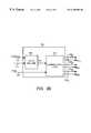
- FIG. 3is a schematic diagram showing switching elements in the spindle motor driver of FIG. 2A connected to terminals of the windings A, B, C.
- FIG. 4Ais a state diagram for the register-state sequencer of FIG. 2 B.
- FIG. 4Bshows a superimposed set of torque curves, each torque curve corresponding to a respective one of the register states in the state diagram of FIG. 4 A.
- FIG. 5is a graph showing a velocity curve concerning deceleration of the rotor in response to a spin-down command.
- FIGS. 6A, 6 B, 6 C and 6 Dare all diagrams having a common abscissa representing time during the controlled rotor-stopping operation
- FIG. 6Ashows a commutation clock signal for selecting and maintaining a single register state during the controlled rotor-stopping operation
- FIG. 6Bshows applied torque on the rotor while a single register state is maintained during the controlled rotor-stopping operation
- FIG. 6Cis a spin-direction/frictional torque diagram showing the spin-direction of the rotor and corresponding frictional torque T f opposing the spin-direction during the controlled rotor-stopping operation;
- FIG. 6Dshows an energy curve concerning the total energy in the spindle motor during the controlled rotor-stopping operation
- FIG. 6Eshows a velocity curve concerning deceleration of the rotor during the controlled-rotor stopping operation.
- FIG. 7is a graph showing a velocity curve illustrating the velocity of the rotor during a representative operation of spinning up the rotor to normal operating spin rate.
- FIG. 8is a flow chart for operating the spindle motor in the disk drive of FIG. 2 .
- a disk drive 200 embodying the inventioncomprises an HDA and a PCBA.
- the HDAincludes a spindle motor 202 having a stator comprising windings A, B, and C.
- the spindle motor 200has a rotor 204 that is rotatable about the stator desirably in a forward-spin direction and undesirably in a reverse-spin direction.
- the HDAincludes a disk 206 supported by the rotor 204 .
- the HDAincludes a head stack assembly (“HSA”) 212 , and structure that cooperates with the HSA 212 to define a voice coil motor (“VCM 214 ”).
- the HSA 212includes transducers 208 A and 208 B for writing and reading data to and from the recording surfaces of the disk 206 .
- the PCBAincludes circuitry that functionally defines a host interface and disk controller (“controller 220 ”), a microprocessor 230 , a memory unit 240 , a spindle motor driver 250 , a voice coil motor driver (“VCM driver 290 ”), and a host connector 299 for connecting the controller 220 to an external host.
- Memory unit 240includes control routines (instructions) for controlling the overall operation of the spindle motor 202 .
- the PCBAincludes a parallel bus 298 and a serial bus for interconnecting the microprocessor 230 and other IC chips on the PCBA.
- microprocessor 230includes a register 236 for storing a flag indicating whether a controlled rotor-stopping operation has been successfully completed.
- the flagcan be stored in a register defined by a memory location in the memory unit 240 .
- the spindle motor driver 250includes a register-state sequencer 252 , a BEMF detector 256 , and switching elements 270 , 272 , and 274 .
- the controller 220communicates with the BEMF detector 256 by receiving a zero crossing signal 257 .
- the zero crossing signal 257is a timing signal that identifies the instant at which a zero crossing occurs in the BEMF induced in a floating winding as a result of the floating winding acting like an AC voltage generator.
- the controller 220communicates with the register-state sequencer 252 by sending a COM-CLK signal 234 .
- the controller 220communicates with the microprocessor 230 via the parallel bus 298 by sending a spin-down command 221 , a zero crossing information signal 222 , and a spin-up command 223 , and by receiving a commutation command 231 .
- the microprocessor 230communicates with the register-state sequencer 252 by sending a serial interface command 232 and a PWM control signal 233 .
- Microprocessor 230produces the PWM control signal to control spin rate of rotor 204 during an ending portion of the spin-up procedure and throughout the run mode of operation, and during a beginning portion of the spin-down procedure.
- the register-state sequencer 252includes a state machine 280 and combinatorial logic 282 .
- the state machine 280receives the serial interface command 232 , the PWM control signal 233 , and the commutation clock signal 234 .
- the state machine 280provides a register state signal 281 to combinatorial logic 282 .
- the combinatorial logic 282also receives the PWM signal 233 .
- the combinatorial logic 282provides six output signals collectively identified as 252 A in FIG. 2 B. These are: 258 H, 258 L, 260 H, 260 L, 262 H, and 262 L.
- the stator windings A, B, and Care electrically arranged in a Y configuration and have a center tap CT.
- Winding Ahas a terminal 202 A.
- Winding Bhas a terminal 202 B.
- Winding Chas a terminal 202 C.
- Spindle motor driver 250includes switching elements 270 , 272 , and 274 .
- Switching element 270is connected to terminal 202 A of winding A.
- Switching element 272is connected to terminal 202 B of winding B.
- Switching element 274is connected to terminal 202 C of winding C.
- Switching element 270includes an upper transistor 270 H having its source connected to a positive voltage, and a lower transistor 270 L having its drain connected to ground.
- Switching element 272includes an upper transistor 272 H having its source connected to a positive voltage, and a lower transistor 272 L connected ground.
- Switching element 274includes an upper transistor 274 H having its source connected to a positive voltage, and its lower transistor 274 L connected to ground.
- bipolar modecan be used whereby switching elements 270 , 272 , and 274 are controlled to cause current to flow through all the windings A, B, C.
- unipolar modecan be used, whereby switching elements are controlled to cause current to flow through the centertap and one at a time of the windings A, B, C.
- Switching elements 270 , 272 , and 274are controlled to cause current to flow in one of six possible current directions 1-6 through windings A, B, C in the bipolar mode.
- a state diagram 400shows a set of eight register states; these are: six register states for phase A through phase F, a register state for brake, and a register state for coast.
- Six of the transitions in the state diagram A ⁇ circle around (10+L ) ⁇ B, B ⁇ circle around (10+L ) ⁇ C, C ⁇ circle around (10+L ) ⁇ D, D ⁇ circle around (10+L ) ⁇ E, E ⁇ circle around (10+L ) ⁇ F, and F ⁇ circle around (10+L ) ⁇ Aconnect six of the states in a circle and indicate a cyclical sequence through which the state machine repeatedly steps throughout various intervals of time.
- Table Iis a truth table showing the correspondence between each of the set of eight register states and the conditions of switching elements 270, 272, and 274 (whether H, L, or X).
- the condition Hindicates that the upper transistor in a switching element ( 270 , 272 , or 274 ) is conducting to provide a +V voltage to the terminal of the winding (A, B, or C) connected to the switching element.
- the condition Lindicates that the lower transistor in a switching element ( 270 , 272 , or 274 ) is conducting, and thereby grounds the terminal of the winding (A, B, or C) that is connected to the switching element. If either transistor in a switching element ( 270 , 272 , or 274 ) is conducting, the switching element is a “driven switching element.”
- the winding (A, B, or C) connected to the driven switching elementis a “driven winding” or “energized winding.”
- the condition Xindicates that neither the upper nor the lower transistor of a switching element ( 270 , 272 , or 274 ) is conducting, wherein the terminal of the winding (A, B, or C) connected to the switching element “floats” and no current flows through 16 that winding. If neither transistor in a switching element ( 270 , 272 , or 274 ) is conducting, the switching element is a “tristated switching element” (or “undriven switching element”). The winding (A, B, or C) connected to the tristated switching element is a “floating winding.”
- Register states for Phases A-Fdefine the conditions (H, L, or X) for controlling switching elements 270 , 272 , and 274 to cause current to flow in one of the six possible current directions 1-6 through windings A, B, C for the bipolar mode.
- the register state for Brakedefines the condition (L, L, L) for controlling switching elements to short the windings and cause current to flow from the windings A, B, C to ground to decelerate rotor 204 .
- the register state for Coastdefines the condition (X, X, X) for controlling switching elements 270 , 272 , and 274 to “float” the windings A, B, C so that no current flows through the windings.
- rotor 204coasts—i.e., continues to rotate subject to deceleration from frictional forces.
- the magnitude of the applied torque acting on the rotor while maintaining each register stateis a function of the magnitude and direction of current flowing through the windings A, B, C, and the angular position of the rotor relative to the stator.
- K tis a torque constant for the design of spindle motor 202
- I coilis the magnitude of current flowing through the windings A, B, C.
- the variable I coilcan be characterized by the equation V + R coil - Vbemf R coil ,
- V +is the voltage applied to the terminals of the windings A, B, C.
- Vbemfis the voltage associated with the back electromotive force induced in the windings A, B, C by the rotating permanent magnet of the rotor.
- R coilis the resistance of windings A, B, C.
- Vbemfis equal to Ke* ⁇ , where Ke is the voltage constant of spindle motor 202 (i.e. the Bemf factor) and O is the rotational velocity of rotor 204 .
- the peak magnitude of the Vbemf in the windingsis proportional to the velocity of rotor 204 . As the velocity of rotor 204 increases, the peak magnitude of the Vbemf in the windings A, B, C increases.
- a set of torque curves 450includes torque curves T1-T6 corresponding to register states for Phases A-F.
- Each torque curveis periodic and substantially sinusoidal in shape.
- transitionsare made in a cyclical sequence to step through the register states for Phases A-F and to the register state for Phase A again to cause current to flow through the windings to generate a substantially continuous positive torque on the rotor.
- the rotorspins at the desired spin rate because a sufficient positive torque is continuously applied to the rotor to oppose frictional torques.
- the continuously applied positive applied torqueacts on the rotor because the state machine 280 (FIG. 2B) is sequentially set in a cycle through states identified in FIG. 4A as register state for Phase A through F, and back to A again.
- this stepping cyclically through these register statescauses applied torque on the motor to define a continuously positive torque with a ripple component whereby the torque curve T1 is active until ideally the magnitude of its torque is less than the magnitude of the torque curve T2 at which time switching occurs between register states, and so forth through the cycle of register states.
- Selecting the register state for Brakecauses current to flow through windings A, B, C to generate a decaying negative torque on the rotor. Selecting the register state for Coast causes rotor 204 to coast. Frictional forces in disk drive 202 contribute to decelerating rotor 204 .
- the spin-down procedureconcludes with a controlled rotor stopping operation.
- a register in the state machineis set to and maintained in a first predetermined one of the register states for Phases A-F such that at the end of the controlled rotor-stopping operation, the rotor stops at a rotor angle within the range of the peaked forward-direction waveform for the second predetermined register state.
- microprocessor 230Upon microprocessor 230 receiving a spin-down command, microprocessor 230 retrieves and executes the spin-down instructions stored in memory unit 240 .
- controller 220receives a command from the host computer to generate the spin-down command 221 to initiate performance of a spin-down procedure while the rotor 204 is spinning in the forward-spin direction at normal operating spin rate.
- controller 220generates spin-down command 221 while rotor 204 is spinning at a velocity less than the operating velocity.
- Microprocessor 230receives spin-down command 221 from controller 220 and then executes the spin-down instructions retrieved from memory unit 240 .
- microprocessor 230generates the spin-down command and then executes the spin-down instructions retrieved from memory unit 240 .
- Microprocessor 230provides VCM control signal 289 to VCM driver 290 .
- VCM driver 290receives VCM control signal 289 and provides a VCM control signal 291 to voice coil motor 214 for positioning transducers 208 A and 208 B in a parking zone on disk 206 .
- transducers 208 A and 208 Bare loaded on a ramp to remove transducers 208 A and 208 B from disk 206 .
- microprocessor 230waits for a time period which is sufficient to complete parking transducers 208 A and 208 B before proceeding to the spin-down operation.
- the spin-down procedurestarts when a transition is made from an arbitrary one of the register states, for example, register state E as depicted in FIG. 4 A. This transition changes the state of state machine 280 to its brake state.
- Microprocessor 230provides a deceleration command via a serial interface command 232 to set a register in state machine 280 to initiate reducing the velocity of the rotor 204 .
- the deceleration commandinitiates a phase of operation involving alternate braking and coasting.
- the brake stateis temporarily set to cause shorting of the windings A, B, C to “brake” the rotor for a brake period P1 and the coast state is temporarily set to float the windings A, B, C to coast rotor 204 for a coast period P2, until the velocity of the rotor is below a threshold velocity ⁇ 1.
- controller 220receives zero crossing signal 257 and provides the zero crossing information signal 222 to microprocessor 230 .
- Microprocessor 230receives the zero crossing information signal 222 and computes the velocity of rotor 204 .
- microprocessor 230receives zero crossing signal 257 from bemf detector 256 and computes the velocity of rotor 204 .
- the threshold velocity ⁇ 1is selected such that bemf in the windings A, B, C can be reliably used for detecting zero crossings of the bemf to (1) compute the velocity of rotor 204 during coast period P2, and (2) optimize the time for selecting and maintaining a register state during the deceleration/alignment period of the spin-down mode of operation.
- the duration for brake period P1is selected to brake the rotor rapidly without undue heat generation.
- the duration for coast period P2is selected to provide sufficient time for computing the velocity of rotor 204 .
- FIG. 4Aillustrates the above-described cycle of coast state and brake state by showing a transition from the brake state to the coast state then a block labeled “CHECK SPEED” in connection with the transition between the coast state and the brake state.
- the “CHECK SPEED” boxrepresents a branch in the flow that depends upon whether the rotor spin rate has been reduced below the threshold spin rate ⁇ 1. If so, the next transition proceeds along a line labeled “ALIGN OPERATION” to a first predetermined register state, for example, register state for Phase B. Alternatively, the next transition can proceed to the brake state for a final brake period before proceeding along the line labeled “ALIGN OPERATION” to the first predetermined register state.
- microprocessor 230provides a spin-down commutation command 231 via parallel bus 298 to controller 220 .
- a substantially continuous negative applied torqueacts on the rotor to decelerate (or “brake”) rotor 204 until the velocity reaches the threshold velocity ⁇ 1.
- State machine 280receives the deceleration command from microprocessor 230 via interface command 232 and generates a state signal 281 representing the selected state.
- state machine 280receives commutation clock signal 234 from controller 220 to advance from a present register state to a next register state, and generates state signal 281 representing the selected (present) register state.
- Combinatorial logic 282receives state signal 281 and generates switch control signals 252 A in accordance with the conditions set forth in Table 1.
- Controller 220receives the deceleration/alignment commutation command 231 from microprocessor 230 via parallel bus 298 and generates commutation clock signal 234 having a single pulse for advancing to and maintaining the single register state.
- microprocessor 230provides an initialization command via serial interface command 232 to state machine 280 for selecting and maintaining a specific register state.
- microprocessor 230provides an initialization command via interface command 232 to state machine 280 to select the register state for Phase B.
- State machine 280receives commutation clock signal 234 from controller 220 and generates state signal 281 representing the selected register state.
- state machine 280receives the initialization command from microprocessor 230 via serial interface command 232 and generates state signal 281 representing the selected register state.
- Combinatorial logic 282receives state signal 281 and generates switch control signals 252 A in accordance with the conditions defined by the selected register state. The selected register state is maintained for the deceleration/alignment period.
- microprocessor 230At the end of the deceleration/alignment period, microprocessor 230 records in the register 236 a completion signal indicating completion of the deceleration/alignment period. Suitably, microprocessor 230 sets a flag in register 236 indicating completion of the deceleration/alignment period (the controlled rotor-stopping operation).
- a velocity curve 500illustrates the velocity of rotor 204 during the spin-down mode of operation.
- the spin-down mode of operationbegins at time to and ends at time t f .
- the spin-down mode of operationhas a deceleration period 502 for reducing the velocity of spindle motor to a velocity below the threshold velocity ⁇ 1, and a deceleration/alignment period 504 (the controlled rotor-stopping operation) for selecting and maintaining a first predetermined register state while reducing the velocity of rotor 204 to zero, thereby causing the rotor to be aligned with the stator (that is, the rotor stops at a rotor angle within the range of the peaked forward-direction waveform for a second predetermined register state).
- the spin-down mode of operationhas deceleration/alignment period 504 only Deceleration period 502 begins when the velocity of rotor 204 is at operating velocity ⁇ operating at time t 0 and ends when the rotor velocity has decreased to below the threshold velocity range ⁇ 1 at time t a .
- Deceleration/alignment period 504begins when the velocity has been reduced below the threshold velocity ⁇ 1 at time t a and ends at time t f .
- microprocessor 230provides a deceleration-braking command via serial interface command 232 to state machine 280 for selecting the brake state for shorting the windings A, B, C for a brake period P1 ( 506 ).
- microprocessor 230provides a deceleration-coast command via serial interface command 232 to state machine 280 for selecting the coast state for floating the windings A, B, C for a coast period P2 ( 508 ). While the coast state is selected, microprocessor 230 receives the zero crossing information signal 222 from controller 220 and computes the velocity of spindle motor 220 .
- microprocessor 230If the velocity of the rotor has not been reduced below the threshold velocity ⁇ 1, microprocessor 230 provides the deceleration-brake command via serial interface command 232 to state machine 280 for shorting the windings for a brake period P3 ( 510 ). Preferably, brake period P3 is shorter than brake period P1. At the end of brake period P3, microprocessor 230 provides the deceleration-coast command via serial interface command 232 to state machine 280 for selecting the coast state for floating the windings for the coast period P2. While the coast state is selected, microprocessor 230 receives the zero crossing information signal 222 from controller 220 and computes the velocity of spindle motor 220 .
- Microprocessor 230repeats the cycle of providing deceleration-shorting command for the brake period P3 ( 510 ) and deceleration-coasting command for the coat period P2 ( 508 ) until the velocity of rotor 204 is reduced below the threshold velocity ⁇ 1.
- microprocessor 230initiates an alignment command to begin deceleration/alignment period 504 .
- Microprocessor 230provides a deceleration/alignment commutation command 231 via parallel bus 298 to controller 220 .
- the deceleration/alignment commutation commandprovides timing information for advancing to and maintaining the next register state which is for Phase B.
- Controller 220receives the deceleration/alignment commutation command 231 via parallel bus 298 and generates a commutation clock signal 234 having a single pulse 604 for advancing to and maintaining the register state for Phase B.
- microprocessor 230provides an initialization command via serial interface command 232 to state machine 280 for selecting and maintaining register state for Phase B during deceleration/alignment period 504 .
- State machine 280receives commutation clock signal 234 from controller 220 , and generates state signal 281 representing the next register state (which corresponds to Phase B). Alternatively, state machine 280 receives the initialization command from microprocessor 230 via serial interface command 232 and generates state signal 281 representing the next register state. Combinatorial logic 282 receives state signal 281 and generates switch control signals 252 A in accordance with the conditions associated with the register state for Phase B.
- FIGS. 6A, 6 B, 6 C, 6 D and 6 Eare all diagrams having a common abscissa representing time during deceleration/alignment period 504 (the controlled rotor-stopping operation). Deceleration/alignment period 504 includes time period A, time period B, time period C, and time period D.
- FIGS. 6A-6Eillustrate the relationship between the selected register state (FIG. 6 A), the electromagnetic torque generated (FIG. 6 B), the spin-direction and opposing frictional torque (FIG. 6 C), the total energy in the spindle motor (FIG. 6 D), and rotational velocity of rotor 204 (FIG. 6E) during time periods A-D.
- register state for Phase Bis maintained during deceleration/alignment period 504 to cause current to flow through the windings B-A while reducing the velocity of rotor 204 to zero at the end of time period C thereby causing the rotor to be aligned.
- the rotor angleis within the range of the peaked forward-direction wave form for a second predetermined register state, for example, the register state for Phase C (FIG. 4 A).
- the register state for phase Bremains selected and maintained until the end of time period D (which is the end of deceleration/alignment period 504 at time t f ).
- torque curve 620illustrates applied torque (“electromagnetic torque”) on the rotor while maintaining the register state for Phase B during time periods A-D (deceleration/alignment period 504 ).
- the electromagnetic torque applied on rotor 204results from the interaction between the stator electromagnetic field with the rotor magnetic field.
- the electromagnetic torquehas a magnitude that varies as a function of the rotor angle.
- spin-direction diagram 625illustrates the forward (FWD) and reverse (REV) spin directions of rotor 204 .
- Frictional torque diagram 627illustrates the corresponding frictional torque T f opposing the spin-direction (and the rotational velocity) of rotor 204 during time periods A-D.
- energy curve 630illustrates the energy in the spindle motor during time periods A-D.
- the spindle motorhas electromagnetic potential and kinetic energy that cause it to continue rotating before coming to a stop at the end of time period C.
- the electromagnetic potential energyis a function of the peak electromagnetic torque, and the angular displacement of rotor 204 relative to the stable equilibrium position (SEP) on the torque curve (such as torque curve T1 of FIG. 4B) corresponding to the selected and maintained register state for Phase B.
- the kinetic energydepends on the rotational velocity of rotor 204 and the inertia of the spindle motor and the disks supported by the spindle motor. When the rotational velocity of rotor 204 is zero, the kinetic energy is zero. When rotor 204 is at the stable equilibrium position (SEP) on the torque curve, the potential energy is zero.
- velocity curve 635illustrates the rotational velocity of rotor 204 during time periods A-D. Frictional torque in the disk drive reduces the kinetic energy and the rotational velocity of rotor 204 .
- the electromagnetic torque generatedfollows a sinusoidal waveform because rotor 204 completely rotates through 360 electrical degrees of a torque curve (such as torque curve T1 of FIG. 4 B).
- a torque curvesuch as torque curve T1 of FIG. 4 B.
- the frictional torquereduces the peak rotational velocity of rotor 204
- rotor 204continues to rotate in the forward-spin direction due to the kinetic energy remaining in the spindle motor.
- the electromagnetic potential energyprevents rotor 204 from coming to a final stop, thereby causing rotor 204 to rotate in the reverse-spin direction at the beginning of time period B.
- rotor 204comes to a final stop when the kinetic energy equals zero and the electromagnetic torque generated (due to the electromagnetic potential energy) is less than the frictional torque.
- Rotor 204stops at or near the stable equilibrium point (SEP) on the torque curve corresponding to the selected and maintained register state for Phase B. Accordingly, rotor 204 stops at a rotor angle within the range of the peaked forward-direction waveform for a second predetermined register state (such as the register state for Phase C or D).
- microprocessor 230sets a flag in register 236 indicating completion of deceleration/alignment period 504 .
- a subsequent spin-up mode of operationcommences essentially immediately with a blind acceleration period and a bemf acceleration period for spinning up rotor 204 from rest to an operating velocity.
- a spin-up velocity curve 700illustrates the velocity of rotor 204 during the subsequent spin-up mode of operation.
- the spin-up mode of operationhas a blind acceleration period 702 that begins at time ⁇ circumflex over (t) ⁇ 0 and ends at time ⁇ circumflex over (t) ⁇ 1 , and a bemf acceleration period 704 that begins at time ⁇ circumflex over (t) ⁇ 1 and ends at time ⁇ circumflex over (t) ⁇ 2 . Because the rotor was aligned with the stator during deceleration/alignment period (such as period 504 of FIG. 5) of the previous spin-down mode of operation, the subsequent spin-up mode of operation can bypass an alignment period (such as period 110 in prior art FIG. 1D) and immediately proceed to begin blind acceleration period 702 , thereby reducing the time for spinning up rotor 204 .
- an alignment periodsuch as period 110 in prior art FIG. 1D
- a subsequent spin-up mode of operationhas an alignment period for aligning the rotor with the stator before beginning blind acceleration period 702 .
- the alignment period during the spin-up mode of operationincreases the time for spinning up rotor 204 from rest to the operating velocity.
- Controller 220receives a command from the host computer to generate the spin-up command 223 while rotor 204 is at rest to begin the spin-up mode of operation.
- Microprocessor 230receives spin-up command 223 from controller 220 and retrieves the control routine for the spin-up mode of operation from memory unit 240 .
- Microprocessor 230reads register 236 to determine whether a flag had been set during the previous spin-down procedure to indicate successful completion of the controlled rotor stopping operation.
- microprocessor 230determines that the flag has been set in register 236 , microprocessor 230 immediately provides a spin-up commutation command 231 via parallel bus 298 to controller 220 .
- the spin-up commutation commandprovides timing information for advancing between register states for Phases A-F in a manner to generate a substantially continuous positive torque on the rotor to accelerate rotor 204 from rest to an operating velocity.
- the commutation commandprovides timing information so that the time between register states decreases as the velocity of rotor 204 increases.
- Microprocessor 230provides a reset command via serial interface command 232 to state machine 280 for resetting state machine 280 to a default register state (such as the register state for Phase B).
- Microprocessor 230provides a commutation command to controller 220 for advancing from the default register state to a starting register state (such as the register state for C or D).
- the starting register stateis within the next two register states from the register state selected and maintained during the deceleration/alignment period 504 of the spin-down mode of operation.
- the starting register statecan be the same as the register state selected and maintained during the deceleration/alignment period 504 of the spin-down mode of operation.
- microprocessor 230provides an initialization command via serial interface command 232 to state machine 280 for initializing state machine 280 to start from the starting register state (such as the register state for Phase B, C or D).
- controller 220receives the spin-up commutation command 231 from microprocessor 230 via parallel bus 298 and generates commutation clock signal 234 .
- controller 220receives zero crossing signal 257 and optimizes the spin-up commutation pattern signal to generate commutation clock signal 234 such that the timing for advancing between register states causes a substantially continuous positive peak torque on the rotor.
- State machine 252receives commutation clock signal 234 from controller 220 and generates state signal 281 representing the selected register state.
- Combinatorial logic 282receives state signal 281 and generates switch control signals 252 A in accordance with the conditions defined by the selected register state.
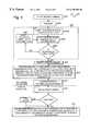
- flow chart 800sets forth the method of operating rotor 204 described above.
- controller 220receives a command from the host computer to send spin-down command 221 to microprocessor 230 via parallel bus 298 .
- Microprocessor 230receives spin-down command 221 from controller 220 and retrieves the spin-down instructions from memory unit 240 .
- microprocessor 230generates the spin-down command and then retrieves the spin-down instructions from memory unit 240 .
- microprocessor 230provides VCM control signal 289 to VCM driver 290 for positioning transducers 208 A and 208 B in a parking zone on disk 206 or alternatively to an unloading position.
- microprocessor 230waits for a time period which is sufficient for completing step 804 before proceeding to step 806 .
- Step 806the spin-down operation starts when a transition is made from an arbitrary one of the register states for Phases A-F, for example, register state for Phase E, to the register state for brake.
- Step 806includes a phase of operation involving alternate braking and coasting until the velocity of the rotor decreases below a threshold velocity ⁇ 1.
- microprocessor 230provides a deceleration-brake command via serial interface command 232 to state machine 280 for selecting the brake state for shorting the windings A, B, C for a brake period P1.
- microprocessor 230provides a deceleration-coast command via serial interface command 232 to state machine 280 for selecting the coast state for floating the windings A, B, C for a coast period P2.
- microprocessor 230receives the zero crossing information signal 222 and computes the velocity of rotor 204 .
- microprocessor 230compares the velocity of rotor 204 to a threshold velocity ⁇ 1. If the velocity is not below the threshold velocity ⁇ 1, microprocessor 230 proceeds to step 806 d to provide the deceleration-brake command via serial interface command 232 to state machine 280 for shorting the windings for a brake period P3.
- microprocessor 230initiates an alignment command to begin deceleration/alignment period 504 .
- microprocessor 230provides a deceleration-brake command for selecting the brake state for a final brake period before initiating the alignment command to begin deceleration/alignment period 504 .
- state machine 280is set and maintained at a first predetermined register state such that a controlled rotor-stopping operation is performed such that at the end of the controlled stopping operation the rotor stops at a rotor angle within the range of the peaked-forward-direction waveform for a second predetermined register state.
- microprocessor 230sets a flag in register 236 indicating completion of the controller rotor-stopping operation (deceleration/alignment period 504 ).
- microprocessor 230receives spin-up command 223 and retrieves the spin-up instructions for the spin-up mode of operation from memory unit 240 .
- Microprocessor 230reads register 236 to determine whether a flag is set to indicate completion of the deceleration/alignment period during the previous spin-down mode of operation.
- state machine 280is stepped through a cyclical sequence of register states for Phases A-F to cause current to flow through the windings to accelerate the rotor in the forward-spin direction.
- the second predetermined register stateis within the next two register states from the first predetermined register state selected and maintained during the deceleration/alignment period of the spin-down mode of operation. If the flag is not set in register 236 , rotor 204 is “cogged” before proceeding to step 816 .
- this cogging stepcan include setting and maintaining (holding) state machine 280 at a first predetermined register state such that at the end of the cogging step the rotor stops at a rotor angle within the range of the peaked-forward-direction waveform for a second predetermined register state.
Landscapes
- Control Of Motors That Do Not Use Commutators (AREA)
Abstract
Description
| TABLE 1 | |||
| Current | Switching | ||
| State | direction |
| 270 | 272 | 274 | ||
| For Phase A | B-C (1) | X | H | L |
| For Phase B | B-A (2) | L | H | X |
| For Phase C | C-A (3) | L | X | H |
| For Phase D | C-B (4) | X | L | H |
| For Phase E | A-B (5) | H | L | X |
| For Phase F | A-C (6) | H | X | L |
| For Brake | A, B, C to | L | L | L |
| (short windings A, B, C) | ground | |||
| For Coast | n/a | X | X | X |
| (float windings A, B, C) | ||||

Claims (6)
Priority Applications (1)
| Application Number | Priority Date | Filing Date | Title |
|---|---|---|---|
| US09/120,854US6198590B1 (en) | 1998-07-21 | 1998-07-21 | Disk drive employing method of spinning down its spindle motor to reduce the time required for subsequently spinning it up |
Applications Claiming Priority (1)
| Application Number | Priority Date | Filing Date | Title |
|---|---|---|---|
| US09/120,854US6198590B1 (en) | 1998-07-21 | 1998-07-21 | Disk drive employing method of spinning down its spindle motor to reduce the time required for subsequently spinning it up |
Publications (1)
| Publication Number | Publication Date |
|---|---|
| US6198590B1true US6198590B1 (en) | 2001-03-06 |
Family
ID=22392927
Family Applications (1)
| Application Number | Title | Priority Date | Filing Date |
|---|---|---|---|
| US09/120,854Expired - LifetimeUS6198590B1 (en) | 1998-07-21 | 1998-07-21 | Disk drive employing method of spinning down its spindle motor to reduce the time required for subsequently spinning it up |
Country Status (1)
| Country | Link |
|---|---|
| US (1) | US6198590B1 (en) |
Cited By (125)
| Publication number | Priority date | Publication date | Assignee | Title |
|---|---|---|---|---|
| US6549359B1 (en)* | 2000-04-19 | 2003-04-15 | Western Digital Technologies, Inc. | Disk drive comprising spin down circuitry having a current limit circuit for enhancing power and braking control |
| US20030115413A1 (en)* | 2001-12-13 | 2003-06-19 | Seagate Technology Llc | Data storage array spin-up control |
| US6598000B1 (en)* | 2000-08-18 | 2003-07-22 | Stmicroelectronics, Inc. | Method and apparatus for detecting motion of a motor for a disk drive system |
| US6611658B1 (en)* | 1999-11-25 | 2003-08-26 | Matsushita Electric Industrial Co., Ltd. | Disk device and disk decelerating and stopping method for the same |
| US20030163296A1 (en)* | 2002-02-28 | 2003-08-28 | Zetacon Corporation | Predictive control system and method |
| US6628470B1 (en)* | 1999-09-16 | 2003-09-30 | Hitachi, Ltd. | Magnetic disk apparatus slowing down rotation speed of disk in idle time |
| US20040036436A1 (en)* | 2002-08-20 | 2004-02-26 | Tieu Triet Minh | Rotor position determination for a multi-phase motor |
| US20040100215A1 (en)* | 2002-11-21 | 2004-05-27 | Tsai-Hsin Tsai | Control device and method of stopping spindle motor of an optical disc system |
| US6819072B2 (en)* | 2000-12-18 | 2004-11-16 | Texas Instruments Incorporated | Disk drive servo arm retract and spindle brake circuit |
| US20040245950A1 (en)* | 2003-06-06 | 2004-12-09 | Ang June Christian | Electrical phase compensation in BEMF spindle motor control |
| US20040251861A1 (en)* | 2003-06-05 | 2004-12-16 | Tieu Triet Minh | Spindle motor acceleration control |
| US6906485B2 (en)* | 2001-11-05 | 2005-06-14 | Seagate Technology Llc | Spindle motor control using a current profile to taper current transitions |
| US20060080483A1 (en)* | 2004-09-30 | 2006-04-13 | Hitachi Global Storage Technologies Netherlands B.V. | Disk device for serial communication and method of controlling the same |
| US20060097681A1 (en)* | 2003-06-06 | 2006-05-11 | Seagate Technology Llc | Electrical phase compensation in BEMF spindle motor control |
| US7158329B1 (en) | 2005-05-23 | 2007-01-02 | Western Digital Technologies, Inc. | Disk drive employing active braking using inductive sense |
| US20070091497A1 (en)* | 2005-10-25 | 2007-04-26 | Makio Mizuno | Control of storage system using disk drive device having self-check function |
| US7253582B1 (en) | 2004-05-28 | 2007-08-07 | Western Digital Technologies, Inc. | Disk drive estimating angular position of spindle motor during spin-up by computing differences in winding current rise times |
| US20080048595A1 (en)* | 2006-08-22 | 2008-02-28 | Seagate Technology, Llc | Active brake for spindle motor |
| US20090168221A1 (en)* | 2007-12-28 | 2009-07-02 | Peter Michael Baumgart | Method and system for detecting a change in a rotational velocity of a magnetic disk or a spindle coupled to the magnetic disk |
| US8610391B1 (en) | 2011-06-29 | 2013-12-17 | Western Digital Technologies, Inc. | Disk drive optimizing spindle motor torque by adjusting leading phase angle during spin-up |
| US8824081B1 (en) | 2012-03-13 | 2014-09-02 | Western Digital Technologies, Inc. | Disk drive employing radially coherent reference pattern for servo burst demodulation and fly height measurement |
| US8830617B1 (en) | 2013-05-30 | 2014-09-09 | Western Digital Technologies, Inc. | Disk drive adjusting state estimator to compensate for unreliable servo data |
| US8879191B1 (en) | 2012-11-14 | 2014-11-04 | Western Digital Technologies, Inc. | Disk drive modifying rotational position optimization algorithm to achieve target performance for limited stroke |
| US8891194B1 (en) | 2013-05-14 | 2014-11-18 | Western Digital Technologies, Inc. | Disk drive iteratively adapting correction value that compensates for non-linearity of head |
| US8891191B1 (en) | 2014-05-06 | 2014-11-18 | Western Digital Technologies, Inc. | Data storage device initializing read signal gain to detect servo seed pattern |
| US8896957B1 (en) | 2013-05-10 | 2014-11-25 | Western Digital Technologies, Inc. | Disk drive performing spiral scan of disk surface to detect residual data |
| US8902539B1 (en) | 2014-05-13 | 2014-12-02 | Western Digital Technologies, Inc. | Data storage device reducing seek power consumption |
| US8902538B1 (en) | 2013-03-29 | 2014-12-02 | Western Digital Technologies, Inc. | Disk drive detecting crack in microactuator |
| US8913342B1 (en) | 2014-03-21 | 2014-12-16 | Western Digital Technologies, Inc. | Data storage device adjusting range of microactuator digital-to-analog converter based on operating temperature |
| US8917474B1 (en) | 2011-08-08 | 2014-12-23 | Western Digital Technologies, Inc. | Disk drive calibrating a velocity profile prior to writing a spiral track |
| US8917475B1 (en) | 2013-12-20 | 2014-12-23 | Western Digital Technologies, Inc. | Disk drive generating a disk locked clock using radial dependent timing feed-forward compensation |
| US8922931B1 (en) | 2013-05-13 | 2014-12-30 | Western Digital Technologies, Inc. | Disk drive releasing variable amount of buffered write data based on sliding window of predicted servo quality |
| US8922940B1 (en) | 2014-05-27 | 2014-12-30 | Western Digital Technologies, Inc. | Data storage device reducing spindle motor voltage boost during power failure |
| US8922937B1 (en) | 2012-04-19 | 2014-12-30 | Western Digital Technologies, Inc. | Disk drive evaluating multiple vibration sensor outputs to enable write-protection |
| US8922938B1 (en) | 2012-11-02 | 2014-12-30 | Western Digital Technologies, Inc. | Disk drive filtering disturbance signal and error signal for adaptive feed-forward compensation |
| US8929022B1 (en) | 2012-12-19 | 2015-01-06 | Western Digital Technologies, Inc. | Disk drive detecting microactuator degradation by evaluating frequency component of servo signal |
| US8929021B1 (en) | 2012-03-27 | 2015-01-06 | Western Digital Technologies, Inc. | Disk drive servo writing from spiral tracks using radial dependent timing feed-forward compensation |
| US8934186B1 (en) | 2014-03-26 | 2015-01-13 | Western Digital Technologies, Inc. | Data storage device estimating servo zone to reduce size of track address |
| US8937784B1 (en) | 2012-08-01 | 2015-01-20 | Western Digital Technologies, Inc. | Disk drive employing feed-forward compensation and phase shift compensation during seek settling |
| US8941945B1 (en) | 2014-06-06 | 2015-01-27 | Western Digital Technologies, Inc. | Data storage device servoing heads based on virtual servo tracks |
| US8941939B1 (en) | 2013-10-24 | 2015-01-27 | Western Digital Technologies, Inc. | Disk drive using VCM BEMF feed-forward compensation to write servo data to a disk |
| US8947819B1 (en) | 2012-08-28 | 2015-02-03 | Western Digital Technologies, Inc. | Disk drive implementing hysteresis for primary shock detector based on a more sensitive secondary shock detector |
| US8953278B1 (en) | 2011-11-16 | 2015-02-10 | Western Digital Technologies, Inc. | Disk drive selecting disturbance signal for feed-forward compensation |
| US8953271B1 (en) | 2013-05-13 | 2015-02-10 | Western Digital Technologies, Inc. | Disk drive compensating for repeatable run out selectively per zone |
| US8958169B1 (en) | 2014-06-11 | 2015-02-17 | Western Digital Technologies, Inc. | Data storage device re-qualifying state estimator while decelerating head |
| US8970979B1 (en) | 2013-12-18 | 2015-03-03 | Western Digital Technologies, Inc. | Disk drive determining frequency response of actuator near servo sample frequency |
| US8982501B1 (en) | 2014-09-22 | 2015-03-17 | Western Digital Technologies, Inc. | Data storage device compensating for repeatable disturbance when commutating a spindle motor |
| US8982490B1 (en) | 2014-04-24 | 2015-03-17 | Western Digital Technologies, Inc. | Data storage device reading first spiral track while simultaneously writing second spiral track |
| US8995082B1 (en) | 2011-06-03 | 2015-03-31 | Western Digital Technologies, Inc. | Reducing acoustic noise in a disk drive when exiting idle mode |
| US8995075B1 (en) | 2012-06-21 | 2015-03-31 | Western Digital Technologies, Inc. | Disk drive adjusting estimated servo state to compensate for transient when crossing a servo zone boundary |
| US9001454B1 (en) | 2013-04-12 | 2015-04-07 | Western Digital Technologies, Inc. | Disk drive adjusting phase of adaptive feed-forward controller when reconfiguring servo loop |
| US9007714B1 (en) | 2014-07-18 | 2015-04-14 | Western Digital Technologies Inc. | Data storage device comprising slew rate anti-windup compensation for microactuator |
| US9013824B1 (en) | 2014-06-04 | 2015-04-21 | Western Digital Technologies, Inc. | Data storage device comprising dual read sensors and dual servo channels to improve servo demodulation |
| US9013825B1 (en) | 2014-03-24 | 2015-04-21 | Western Digital Technologies, Inc. | Electronic system with vibration management mechanism and method of operation thereof |
| US9025269B1 (en) | 2014-01-02 | 2015-05-05 | Western Digital Technologies, Inc. | Disk drive compensating for cycle slip of disk locked clock when reading mini-wedge |
| US9026728B1 (en) | 2013-06-06 | 2015-05-05 | Western Digital Technologies, Inc. | Disk drive applying feed-forward compensation when writing consecutive data tracks |
| US9047919B1 (en) | 2013-03-12 | 2015-06-02 | Western Digitial Technologies, Inc. | Disk drive initializing servo read channel by reading data preceding servo preamble during access operation |
| US9047932B1 (en) | 2014-03-21 | 2015-06-02 | Western Digital Technologies, Inc. | Data storage device adjusting a power loss threshold based on samples of supply voltage |
| US9047901B1 (en) | 2013-05-28 | 2015-06-02 | Western Digital Technologies, Inc. | Disk drive measuring spiral track error by measuring a slope of a spiral track across a disk radius |
| US9053712B1 (en) | 2014-05-07 | 2015-06-09 | Western Digital Technologies, Inc. | Data storage device reading servo sector while writing data sector |
| US9053727B1 (en) | 2014-06-02 | 2015-06-09 | Western Digital Technologies, Inc. | Disk drive opening spiral crossing window based on DC and AC spiral track error |
| US9053726B1 (en) | 2014-01-29 | 2015-06-09 | Western Digital Technologies, Inc. | Data storage device on-line adapting disturbance observer filter |
| US9058826B1 (en) | 2014-02-13 | 2015-06-16 | Western Digital Technologies, Inc. | Data storage device detecting free fall condition from disk speed variations |
| US9058834B1 (en) | 2013-11-08 | 2015-06-16 | Western Digital Technologies, Inc. | Power architecture for low power modes in storage devices |
| US9058827B1 (en) | 2013-06-25 | 2015-06-16 | Western Digitial Technologies, Inc. | Disk drive optimizing filters based on sensor signal and disturbance signal for adaptive feed-forward compensation |
| US9064537B1 (en) | 2013-09-13 | 2015-06-23 | Western Digital Technologies, Inc. | Disk drive measuring radial offset between heads by detecting a difference between ramp contact |
| US9076471B1 (en) | 2013-07-31 | 2015-07-07 | Western Digital Technologies, Inc. | Fall detection scheme using FFS |
| US9076473B1 (en) | 2014-08-12 | 2015-07-07 | Western Digital Technologies, Inc. | Data storage device detecting fly height instability of head during load operation based on microactuator response |
| US9076472B1 (en) | 2014-08-21 | 2015-07-07 | Western Digital (Fremont), Llc | Apparatus enabling writing servo data when disk reaches target rotation speed |
| US9076490B1 (en) | 2012-12-12 | 2015-07-07 | Western Digital Technologies, Inc. | Disk drive writing radial offset spiral servo tracks by reading spiral seed tracks |
| US9093105B2 (en) | 2011-12-09 | 2015-07-28 | Western Digital Technologies, Inc. | Disk drive charging capacitor using motor supply voltage during power failure |
| US9099147B1 (en) | 2014-09-22 | 2015-08-04 | Western Digital Technologies, Inc. | Data storage device commutating a spindle motor using closed-loop rotation phase alignment |
| US9111575B1 (en) | 2014-10-23 | 2015-08-18 | Western Digital Technologies, Inc. | Data storage device employing adaptive feed-forward control in timing loop to compensate for vibration |
| US9129630B1 (en) | 2014-12-16 | 2015-09-08 | Western Digital Technologies, Inc. | Data storage device employing full servo sectors on first disk surface and mini servo sectors on second disk surface |
| US9142235B1 (en) | 2009-10-27 | 2015-09-22 | Western Digital Technologies, Inc. | Disk drive characterizing microactuator by injecting sinusoidal disturbance and evaluating feed-forward compensation values |
| US9142249B1 (en) | 2013-12-06 | 2015-09-22 | Western Digital Technologies, Inc. | Disk drive using timing loop control signal for vibration compensation in servo loop |
| US9141177B1 (en) | 2014-03-21 | 2015-09-22 | Western Digital Technologies, Inc. | Data storage device employing glitch compensation for power loss detection |
| US9142225B1 (en) | 2014-03-21 | 2015-09-22 | Western Digital Technologies, Inc. | Electronic system with actuator control mechanism and method of operation thereof |
| US9147418B1 (en) | 2013-06-20 | 2015-09-29 | Western Digital Technologies, Inc. | Disk drive compensating for microactuator gain variations |
| US9147428B1 (en) | 2013-04-24 | 2015-09-29 | Western Digital Technologies, Inc. | Disk drive with improved spin-up control |
| US9153283B1 (en) | 2014-09-30 | 2015-10-06 | Western Digital Technologies, Inc. | Data storage device compensating for hysteretic response of microactuator |
| US9165583B1 (en) | 2014-10-29 | 2015-10-20 | Western Digital Technologies, Inc. | Data storage device adjusting seek profile based on seek length when ending track is near ramp |
| US9171568B1 (en) | 2014-06-25 | 2015-10-27 | Western Digital Technologies, Inc. | Data storage device periodically re-initializing spindle motor commutation sequence based on timing data |
| US9171567B1 (en) | 2014-05-27 | 2015-10-27 | Western Digital Technologies, Inc. | Data storage device employing sliding mode control of spindle motor |
| US9208808B1 (en) | 2014-04-22 | 2015-12-08 | Western Digital Technologies, Inc. | Electronic system with unload management mechanism and method of operation thereof |
| US9208810B1 (en) | 2014-04-24 | 2015-12-08 | Western Digital Technologies, Inc. | Data storage device attenuating interference from first spiral track when reading second spiral track |
| US9208815B1 (en) | 2014-10-09 | 2015-12-08 | Western Digital Technologies, Inc. | Data storage device dynamically reducing coast velocity during seek to reduce power consumption |
| US9214175B1 (en) | 2015-03-16 | 2015-12-15 | Western Digital Technologies, Inc. | Data storage device configuring a gain of a servo control system for actuating a head over a disk |
| US9230593B1 (en) | 2014-12-23 | 2016-01-05 | Western Digital Technologies, Inc. | Data storage device optimizing spindle motor power when transitioning into a power failure mode |
| US9230592B1 (en) | 2014-12-23 | 2016-01-05 | Western Digital Technologies, Inc. | Electronic system with a method of motor spindle bandwidth estimation and calibration thereof |
| US9245560B1 (en) | 2015-03-09 | 2016-01-26 | Western Digital Technologies, Inc. | Data storage device measuring reader/writer offset by reading spiral track and concentric servo sectors |
| US9245577B1 (en) | 2015-03-26 | 2016-01-26 | Western Digital Technologies, Inc. | Data storage device comprising spindle motor current sensing with supply voltage noise attenuation |
| US9245540B1 (en) | 2014-10-29 | 2016-01-26 | Western Digital Technologies, Inc. | Voice coil motor temperature sensing circuit to reduce catastrophic failure due to voice coil motor coil shorting to ground |
| US9251823B1 (en) | 2014-12-10 | 2016-02-02 | Western Digital Technologies, Inc. | Data storage device delaying seek operation to avoid thermal asperities |
| US9269386B1 (en) | 2014-01-29 | 2016-02-23 | Western Digital Technologies, Inc. | Data storage device on-line adapting disturbance observer filter |
| US9286927B1 (en) | 2014-12-16 | 2016-03-15 | Western Digital Technologies, Inc. | Data storage device demodulating servo burst by computing slope of intermediate integration points |
| US9286925B1 (en) | 2015-03-26 | 2016-03-15 | Western Digital Technologies, Inc. | Data storage device writing multiple burst correction values at the same radial location |
| US9343094B1 (en) | 2015-03-26 | 2016-05-17 | Western Digital Technologies, Inc. | Data storage device filtering burst correction values before downsampling the burst correction values |
| US9343102B1 (en) | 2015-03-25 | 2016-05-17 | Western Digital Technologies, Inc. | Data storage device employing a phase offset to generate power from a spindle motor during a power failure |
| US9350278B1 (en) | 2014-06-13 | 2016-05-24 | Western Digital Technologies, Inc. | Circuit technique to integrate voice coil motor support elements |
| US9349401B1 (en) | 2014-07-24 | 2016-05-24 | Western Digital Technologies, Inc. | Electronic system with media scan mechanism and method of operation thereof |
| US9355676B1 (en) | 2015-03-25 | 2016-05-31 | Western Digital Technologies, Inc. | Data storage device controlling amplitude and phase of driving voltage to generate power from a spindle motor |
| US9355667B1 (en) | 2014-11-11 | 2016-05-31 | Western Digital Technologies, Inc. | Data storage device saving absolute position at each servo wedge for previous write operations |
| US9361939B1 (en) | 2014-03-10 | 2016-06-07 | Western Digital Technologies, Inc. | Data storage device characterizing geometry of magnetic transitions |
| US9396751B1 (en) | 2015-06-26 | 2016-07-19 | Western Digital Technologies, Inc. | Data storage device compensating for fabrication tolerances when measuring spindle motor current |
| US9407015B1 (en) | 2014-12-29 | 2016-08-02 | Western Digital Technologies, Inc. | Automatic power disconnect device |
| US9418689B2 (en) | 2014-10-09 | 2016-08-16 | Western Digital Technologies, Inc. | Data storage device generating an operating seek time profile as a function of a base seek time profile |
| US9424871B1 (en) | 2012-09-13 | 2016-08-23 | Western Digital Technologies, Inc. | Disk drive correcting an error in a detected gray code |
| US9424868B1 (en) | 2015-05-12 | 2016-08-23 | Western Digital Technologies, Inc. | Data storage device employing spindle motor driving profile during seek to improve power performance |
| US9437231B1 (en) | 2015-09-25 | 2016-09-06 | Western Digital Technologies, Inc. | Data storage device concurrently controlling and sensing a secondary actuator for actuating a head over a disk |
| US9437237B1 (en) | 2015-02-20 | 2016-09-06 | Western Digital Technologies, Inc. | Method to detect power loss through data storage device spindle speed |
| US9454212B1 (en) | 2014-12-08 | 2016-09-27 | Western Digital Technologies, Inc. | Wakeup detector |
| US9471072B1 (en) | 2013-11-14 | 2016-10-18 | Western Digital Technologies, Inc | Self-adaptive voltage scaling |
| US9484733B1 (en) | 2013-09-11 | 2016-11-01 | Western Digital Technologies, Inc. | Power control module for data storage device |
| US9542966B1 (en) | 2015-07-09 | 2017-01-10 | Western Digital Technologies, Inc. | Data storage devices and methods with frequency-shaped sliding mode control |
| US9564162B1 (en) | 2015-12-28 | 2017-02-07 | Western Digital Technologies, Inc. | Data storage device measuring resonant frequency of a shock sensor by applying differential excitation and measuring oscillation |
| US9581978B1 (en) | 2014-12-17 | 2017-02-28 | Western Digital Technologies, Inc. | Electronic system with servo management mechanism and method of operation thereof |
| US9620160B1 (en) | 2015-12-28 | 2017-04-11 | Western Digital Technologies, Inc. | Data storage device measuring resonant frequency of a shock sensor by inserting the shock sensor into an oscillator circuit |
| US9626997B1 (en)* | 2015-10-30 | 2017-04-18 | Netapp, Inc. | Variable spinning rates for hard disk drives |
| US9823294B1 (en) | 2013-10-29 | 2017-11-21 | Western Digital Technologies, Inc. | Negative voltage testing methodology and tester |
| US9886285B2 (en) | 2015-03-31 | 2018-02-06 | Western Digital Technologies, Inc. | Communication interface initialization |
| US9899834B1 (en) | 2015-11-18 | 2018-02-20 | Western Digital Technologies, Inc. | Power control module using protection circuit for regulating backup voltage to power load during power fault |
| US9959204B1 (en) | 2015-03-09 | 2018-05-01 | Western Digital Technologies, Inc. | Tracking sequential ranges of non-ordered data |
| US20200412222A1 (en)* | 2019-06-14 | 2020-12-31 | Apple Inc. | Haptic actuator having a double-wound driving coil for temperature-independent velocity sensing |
| US11527946B2 (en) | 2019-06-14 | 2022-12-13 | Apple Inc. | Haptic actuator having a double-wound driving coil for temperature- and driving current-independent velocity sensing |
Citations (8)
| Publication number | Priority date | Publication date | Assignee | Title |
|---|---|---|---|---|
| US5223771A (en) | 1991-06-17 | 1993-06-29 | Western Digital (Singapore) Pte., Ltd. | Polyphase brushless DC Motor control |
| US5397972A (en) | 1991-10-31 | 1995-03-14 | Sgs-Thomson Microelectronics, S.R.L. | Start-up procedure for a brushless, sensorless motor |
| US5471353A (en) | 1992-12-18 | 1995-11-28 | Western Digital (Sea), Pte., Ltd. | Disk drive employing multi-mode spindle drive system |
| US5530326A (en) | 1993-07-19 | 1996-06-25 | Quantum Corporation | Brushless DC spindle motor startup control |
| US5623379A (en) | 1994-02-14 | 1997-04-22 | Fujitsu Limited | Method of controlling a start-up of a motor used for a disk apparatus |
| US5633569A (en)* | 1995-03-10 | 1997-05-27 | Texas Instruments Incorporated | Start-up commutation method for a rotating magnetic storage device without back rotation |
| US5633570A (en)* | 1996-02-12 | 1997-05-27 | Seagate Technology, Inc. | Position feedback control of brushless DC motors from standstill |
| US5946155A (en)* | 1994-06-24 | 1999-08-31 | Fujitsu Limited | Disk apparatus using stop patterns to reliably determine a stop position |
- 1998
- 1998-07-21USUS09/120,854patent/US6198590B1/ennot_activeExpired - Lifetime
Patent Citations (9)
| Publication number | Priority date | Publication date | Assignee | Title |
|---|---|---|---|---|
| US5223771A (en) | 1991-06-17 | 1993-06-29 | Western Digital (Singapore) Pte., Ltd. | Polyphase brushless DC Motor control |
| US5397972A (en) | 1991-10-31 | 1995-03-14 | Sgs-Thomson Microelectronics, S.R.L. | Start-up procedure for a brushless, sensorless motor |
| US5471353A (en) | 1992-12-18 | 1995-11-28 | Western Digital (Sea), Pte., Ltd. | Disk drive employing multi-mode spindle drive system |
| US5650886A (en) | 1992-12-18 | 1997-07-22 | Western Digital Corporation | Disk drive spindle motor start up using an additional motor winding upon startup failure |
| US5530326A (en) | 1993-07-19 | 1996-06-25 | Quantum Corporation | Brushless DC spindle motor startup control |
| US5623379A (en) | 1994-02-14 | 1997-04-22 | Fujitsu Limited | Method of controlling a start-up of a motor used for a disk apparatus |
| US5946155A (en)* | 1994-06-24 | 1999-08-31 | Fujitsu Limited | Disk apparatus using stop patterns to reliably determine a stop position |
| US5633569A (en)* | 1995-03-10 | 1997-05-27 | Texas Instruments Incorporated | Start-up commutation method for a rotating magnetic storage device without back rotation |
| US5633570A (en)* | 1996-02-12 | 1997-05-27 | Seagate Technology, Inc. | Position feedback control of brushless DC motors from standstill |
Non-Patent Citations (2)
| Title |
|---|
| Raffi Codilian, Don Stupeck-"A Multi Mode Spindle Selection Within a Disk Drive System," Incremental Motion Control Systems Symposium, 1995. |
| Raffi Codilian, Don Stupeck-"An Optimization Method of Spindle Motor and Driver Selection Within a Disk Drive System," Incremental Motion Systems Symposium, 1995. |
Cited By (142)
| Publication number | Priority date | Publication date | Assignee | Title |
|---|---|---|---|---|
| US6628470B1 (en)* | 1999-09-16 | 2003-09-30 | Hitachi, Ltd. | Magnetic disk apparatus slowing down rotation speed of disk in idle time |
| US6611658B1 (en)* | 1999-11-25 | 2003-08-26 | Matsushita Electric Industrial Co., Ltd. | Disk device and disk decelerating and stopping method for the same |
| US6549359B1 (en)* | 2000-04-19 | 2003-04-15 | Western Digital Technologies, Inc. | Disk drive comprising spin down circuitry having a current limit circuit for enhancing power and braking control |
| US6577465B1 (en)* | 2000-04-19 | 2003-06-10 | Western Digital Technologies, Inc. | Disk drive comprising spin down circuitry having a programmable signal generator for enhancing power and braking control |
| US6598000B1 (en)* | 2000-08-18 | 2003-07-22 | Stmicroelectronics, Inc. | Method and apparatus for detecting motion of a motor for a disk drive system |
| US6819072B2 (en)* | 2000-12-18 | 2004-11-16 | Texas Instruments Incorporated | Disk drive servo arm retract and spindle brake circuit |
| US6906485B2 (en)* | 2001-11-05 | 2005-06-14 | Seagate Technology Llc | Spindle motor control using a current profile to taper current transitions |
| US20030115413A1 (en)* | 2001-12-13 | 2003-06-19 | Seagate Technology Llc | Data storage array spin-up control |
| US6915363B2 (en)* | 2001-12-13 | 2005-07-05 | Seagate Technology Llc | System for selectively controlling spin-up control for data storage devices in an array using predetermined out of band (OOB) signals |
| US7286906B2 (en) | 2002-02-28 | 2007-10-23 | Zetacon Corporation | Predictive control system and method |
| US20030163296A1 (en)* | 2002-02-28 | 2003-08-28 | Zetacon Corporation | Predictive control system and method |
| US7243006B2 (en) | 2002-02-28 | 2007-07-10 | Zetacon Corporation | Predictive control system and method |
| US20070021873A1 (en)* | 2002-02-28 | 2007-01-25 | Zetacon Corporation | Predictive control system and method |
| US20040036436A1 (en)* | 2002-08-20 | 2004-02-26 | Tieu Triet Minh | Rotor position determination for a multi-phase motor |
| US20040100215A1 (en)* | 2002-11-21 | 2004-05-27 | Tsai-Hsin Tsai | Control device and method of stopping spindle motor of an optical disc system |
| US6917171B2 (en)* | 2002-11-21 | 2005-07-12 | Via Technologies, Inc. | Control device and method of stopping spindle motor of an optical disc system |
| US20040251861A1 (en)* | 2003-06-05 | 2004-12-16 | Tieu Triet Minh | Spindle motor acceleration control |
| US7023155B2 (en)* | 2003-06-05 | 2006-04-04 | Seagate Technology Llc | Spindle motor acceleration control |
| US20060097681A1 (en)* | 2003-06-06 | 2006-05-11 | Seagate Technology Llc | Electrical phase compensation in BEMF spindle motor control |
| US20040245950A1 (en)* | 2003-06-06 | 2004-12-09 | Ang June Christian | Electrical phase compensation in BEMF spindle motor control |
| US7170249B2 (en) | 2003-06-06 | 2007-01-30 | Seagate Technology Llc | Electrical phase compensation in BEMF spindle motor control |
| US7253582B1 (en) | 2004-05-28 | 2007-08-07 | Western Digital Technologies, Inc. | Disk drive estimating angular position of spindle motor during spin-up by computing differences in winding current rise times |
| US20060080483A1 (en)* | 2004-09-30 | 2006-04-13 | Hitachi Global Storage Technologies Netherlands B.V. | Disk device for serial communication and method of controlling the same |
| US7613525B2 (en)* | 2004-09-30 | 2009-11-03 | Hitachi Global Storage Technologies Netherlands B.V. | Disk device for serial communication and method of controlling the same |
| US7158329B1 (en) | 2005-05-23 | 2007-01-02 | Western Digital Technologies, Inc. | Disk drive employing active braking using inductive sense |
| US7519869B2 (en)* | 2005-10-25 | 2009-04-14 | Hitachi, Ltd. | Control of storage system using disk drive device having self-check function |
| US20070091497A1 (en)* | 2005-10-25 | 2007-04-26 | Makio Mizuno | Control of storage system using disk drive device having self-check function |
| US20080048595A1 (en)* | 2006-08-22 | 2008-02-28 | Seagate Technology, Llc | Active brake for spindle motor |
| US20090168221A1 (en)* | 2007-12-28 | 2009-07-02 | Peter Michael Baumgart | Method and system for detecting a change in a rotational velocity of a magnetic disk or a spindle coupled to the magnetic disk |
| US7605996B2 (en) | 2007-12-28 | 2009-10-20 | Hitachi Global Storage Technologies Netherlands B.V. | Method and system for detecting a change in a rotational velocity of a magnetic disk or a spindle coupled to the magnetic disk |
| US9142235B1 (en) | 2009-10-27 | 2015-09-22 | Western Digital Technologies, Inc. | Disk drive characterizing microactuator by injecting sinusoidal disturbance and evaluating feed-forward compensation values |
| US8995082B1 (en) | 2011-06-03 | 2015-03-31 | Western Digital Technologies, Inc. | Reducing acoustic noise in a disk drive when exiting idle mode |
| US8610391B1 (en) | 2011-06-29 | 2013-12-17 | Western Digital Technologies, Inc. | Disk drive optimizing spindle motor torque by adjusting leading phase angle during spin-up |
| US8917474B1 (en) | 2011-08-08 | 2014-12-23 | Western Digital Technologies, Inc. | Disk drive calibrating a velocity profile prior to writing a spiral track |
| US8953278B1 (en) | 2011-11-16 | 2015-02-10 | Western Digital Technologies, Inc. | Disk drive selecting disturbance signal for feed-forward compensation |
| US9390749B2 (en) | 2011-12-09 | 2016-07-12 | Western Digital Technologies, Inc. | Power failure management in disk drives |
| US9093105B2 (en) | 2011-12-09 | 2015-07-28 | Western Digital Technologies, Inc. | Disk drive charging capacitor using motor supply voltage during power failure |
| US8824081B1 (en) | 2012-03-13 | 2014-09-02 | Western Digital Technologies, Inc. | Disk drive employing radially coherent reference pattern for servo burst demodulation and fly height measurement |
| US8934191B1 (en) | 2012-03-27 | 2015-01-13 | Western Digital Technologies, Inc. | Disk drive generating a disk locked clock using radial dependent timing feed-forward compensation |
| US8929021B1 (en) | 2012-03-27 | 2015-01-06 | Western Digital Technologies, Inc. | Disk drive servo writing from spiral tracks using radial dependent timing feed-forward compensation |
| US8922937B1 (en) | 2012-04-19 | 2014-12-30 | Western Digital Technologies, Inc. | Disk drive evaluating multiple vibration sensor outputs to enable write-protection |
| US8995075B1 (en) | 2012-06-21 | 2015-03-31 | Western Digital Technologies, Inc. | Disk drive adjusting estimated servo state to compensate for transient when crossing a servo zone boundary |
| US9454989B1 (en) | 2012-06-21 | 2016-09-27 | Western Digital Technologies, Inc. | Disk drive adjusting estimated servo state to compensate for transient when crossing a servo zone boundary |
| US8937784B1 (en) | 2012-08-01 | 2015-01-20 | Western Digital Technologies, Inc. | Disk drive employing feed-forward compensation and phase shift compensation during seek settling |
| US8947819B1 (en) | 2012-08-28 | 2015-02-03 | Western Digital Technologies, Inc. | Disk drive implementing hysteresis for primary shock detector based on a more sensitive secondary shock detector |
| US9424871B1 (en) | 2012-09-13 | 2016-08-23 | Western Digital Technologies, Inc. | Disk drive correcting an error in a detected gray code |
| US8922938B1 (en) | 2012-11-02 | 2014-12-30 | Western Digital Technologies, Inc. | Disk drive filtering disturbance signal and error signal for adaptive feed-forward compensation |
| US8879191B1 (en) | 2012-11-14 | 2014-11-04 | Western Digital Technologies, Inc. | Disk drive modifying rotational position optimization algorithm to achieve target performance for limited stroke |
| US9076490B1 (en) | 2012-12-12 | 2015-07-07 | Western Digital Technologies, Inc. | Disk drive writing radial offset spiral servo tracks by reading spiral seed tracks |
| US8929022B1 (en) | 2012-12-19 | 2015-01-06 | Western Digital Technologies, Inc. | Disk drive detecting microactuator degradation by evaluating frequency component of servo signal |
| US9047919B1 (en) | 2013-03-12 | 2015-06-02 | Western Digitial Technologies, Inc. | Disk drive initializing servo read channel by reading data preceding servo preamble during access operation |
| US8902538B1 (en) | 2013-03-29 | 2014-12-02 | Western Digital Technologies, Inc. | Disk drive detecting crack in microactuator |
| US9001454B1 (en) | 2013-04-12 | 2015-04-07 | Western Digital Technologies, Inc. | Disk drive adjusting phase of adaptive feed-forward controller when reconfiguring servo loop |
| US9147428B1 (en) | 2013-04-24 | 2015-09-29 | Western Digital Technologies, Inc. | Disk drive with improved spin-up control |
| US8896957B1 (en) | 2013-05-10 | 2014-11-25 | Western Digital Technologies, Inc. | Disk drive performing spiral scan of disk surface to detect residual data |
| US8953271B1 (en) | 2013-05-13 | 2015-02-10 | Western Digital Technologies, Inc. | Disk drive compensating for repeatable run out selectively per zone |
| US8922931B1 (en) | 2013-05-13 | 2014-12-30 | Western Digital Technologies, Inc. | Disk drive releasing variable amount of buffered write data based on sliding window of predicted servo quality |
| US8891194B1 (en) | 2013-05-14 | 2014-11-18 | Western Digital Technologies, Inc. | Disk drive iteratively adapting correction value that compensates for non-linearity of head |
| US9047901B1 (en) | 2013-05-28 | 2015-06-02 | Western Digital Technologies, Inc. | Disk drive measuring spiral track error by measuring a slope of a spiral track across a disk radius |
| US8830617B1 (en) | 2013-05-30 | 2014-09-09 | Western Digital Technologies, Inc. | Disk drive adjusting state estimator to compensate for unreliable servo data |
| US9026728B1 (en) | 2013-06-06 | 2015-05-05 | Western Digital Technologies, Inc. | Disk drive applying feed-forward compensation when writing consecutive data tracks |
| US9147418B1 (en) | 2013-06-20 | 2015-09-29 | Western Digital Technologies, Inc. | Disk drive compensating for microactuator gain variations |
| US9058827B1 (en) | 2013-06-25 | 2015-06-16 | Western Digitial Technologies, Inc. | Disk drive optimizing filters based on sensor signal and disturbance signal for adaptive feed-forward compensation |
| US9076471B1 (en) | 2013-07-31 | 2015-07-07 | Western Digital Technologies, Inc. | Fall detection scheme using FFS |
| US9484733B1 (en) | 2013-09-11 | 2016-11-01 | Western Digital Technologies, Inc. | Power control module for data storage device |
| US9064537B1 (en) | 2013-09-13 | 2015-06-23 | Western Digital Technologies, Inc. | Disk drive measuring radial offset between heads by detecting a difference between ramp contact |
| US8941939B1 (en) | 2013-10-24 | 2015-01-27 | Western Digital Technologies, Inc. | Disk drive using VCM BEMF feed-forward compensation to write servo data to a disk |
| US9823294B1 (en) | 2013-10-29 | 2017-11-21 | Western Digital Technologies, Inc. | Negative voltage testing methodology and tester |
| US9058834B1 (en) | 2013-11-08 | 2015-06-16 | Western Digital Technologies, Inc. | Power architecture for low power modes in storage devices |
| US9471072B1 (en) | 2013-11-14 | 2016-10-18 | Western Digital Technologies, Inc | Self-adaptive voltage scaling |
| US9142249B1 (en) | 2013-12-06 | 2015-09-22 | Western Digital Technologies, Inc. | Disk drive using timing loop control signal for vibration compensation in servo loop |
| US8970979B1 (en) | 2013-12-18 | 2015-03-03 | Western Digital Technologies, Inc. | Disk drive determining frequency response of actuator near servo sample frequency |
| US8917475B1 (en) | 2013-12-20 | 2014-12-23 | Western Digital Technologies, Inc. | Disk drive generating a disk locked clock using radial dependent timing feed-forward compensation |
| US9025269B1 (en) | 2014-01-02 | 2015-05-05 | Western Digital Technologies, Inc. | Disk drive compensating for cycle slip of disk locked clock when reading mini-wedge |
| US9053726B1 (en) | 2014-01-29 | 2015-06-09 | Western Digital Technologies, Inc. | Data storage device on-line adapting disturbance observer filter |
| US9269386B1 (en) | 2014-01-29 | 2016-02-23 | Western Digital Technologies, Inc. | Data storage device on-line adapting disturbance observer filter |
| US9058826B1 (en) | 2014-02-13 | 2015-06-16 | Western Digital Technologies, Inc. | Data storage device detecting free fall condition from disk speed variations |
| US9361939B1 (en) | 2014-03-10 | 2016-06-07 | Western Digital Technologies, Inc. | Data storage device characterizing geometry of magnetic transitions |
| US9047932B1 (en) | 2014-03-21 | 2015-06-02 | Western Digital Technologies, Inc. | Data storage device adjusting a power loss threshold based on samples of supply voltage |
| US8913342B1 (en) | 2014-03-21 | 2014-12-16 | Western Digital Technologies, Inc. | Data storage device adjusting range of microactuator digital-to-analog converter based on operating temperature |
| US9141177B1 (en) | 2014-03-21 | 2015-09-22 | Western Digital Technologies, Inc. | Data storage device employing glitch compensation for power loss detection |
| US9142225B1 (en) | 2014-03-21 | 2015-09-22 | Western Digital Technologies, Inc. | Electronic system with actuator control mechanism and method of operation thereof |
| US9013825B1 (en) | 2014-03-24 | 2015-04-21 | Western Digital Technologies, Inc. | Electronic system with vibration management mechanism and method of operation thereof |
| US8934186B1 (en) | 2014-03-26 | 2015-01-13 | Western Digital Technologies, Inc. | Data storage device estimating servo zone to reduce size of track address |
| US9208808B1 (en) | 2014-04-22 | 2015-12-08 | Western Digital Technologies, Inc. | Electronic system with unload management mechanism and method of operation thereof |
| US8982490B1 (en) | 2014-04-24 | 2015-03-17 | Western Digital Technologies, Inc. | Data storage device reading first spiral track while simultaneously writing second spiral track |
| US9208810B1 (en) | 2014-04-24 | 2015-12-08 | Western Digital Technologies, Inc. | Data storage device attenuating interference from first spiral track when reading second spiral track |
| US8891191B1 (en) | 2014-05-06 | 2014-11-18 | Western Digital Technologies, Inc. | Data storage device initializing read signal gain to detect servo seed pattern |
| US9053712B1 (en) | 2014-05-07 | 2015-06-09 | Western Digital Technologies, Inc. | Data storage device reading servo sector while writing data sector |
| US8902539B1 (en) | 2014-05-13 | 2014-12-02 | Western Digital Technologies, Inc. | Data storage device reducing seek power consumption |
| US9171567B1 (en) | 2014-05-27 | 2015-10-27 | Western Digital Technologies, Inc. | Data storage device employing sliding mode control of spindle motor |
| US8922940B1 (en) | 2014-05-27 | 2014-12-30 | Western Digital Technologies, Inc. | Data storage device reducing spindle motor voltage boost during power failure |
| US9053727B1 (en) | 2014-06-02 | 2015-06-09 | Western Digital Technologies, Inc. | Disk drive opening spiral crossing window based on DC and AC spiral track error |
| US9013824B1 (en) | 2014-06-04 | 2015-04-21 | Western Digital Technologies, Inc. | Data storage device comprising dual read sensors and dual servo channels to improve servo demodulation |
| US8941945B1 (en) | 2014-06-06 | 2015-01-27 | Western Digital Technologies, Inc. | Data storage device servoing heads based on virtual servo tracks |
| US8958169B1 (en) | 2014-06-11 | 2015-02-17 | Western Digital Technologies, Inc. | Data storage device re-qualifying state estimator while decelerating head |
| US9350278B1 (en) | 2014-06-13 | 2016-05-24 | Western Digital Technologies, Inc. | Circuit technique to integrate voice coil motor support elements |
| US9171568B1 (en) | 2014-06-25 | 2015-10-27 | Western Digital Technologies, Inc. | Data storage device periodically re-initializing spindle motor commutation sequence based on timing data |
| US9007714B1 (en) | 2014-07-18 | 2015-04-14 | Western Digital Technologies Inc. | Data storage device comprising slew rate anti-windup compensation for microactuator |
| US9349401B1 (en) | 2014-07-24 | 2016-05-24 | Western Digital Technologies, Inc. | Electronic system with media scan mechanism and method of operation thereof |
| US9076473B1 (en) | 2014-08-12 | 2015-07-07 | Western Digital Technologies, Inc. | Data storage device detecting fly height instability of head during load operation based on microactuator response |
| US9076472B1 (en) | 2014-08-21 | 2015-07-07 | Western Digital (Fremont), Llc | Apparatus enabling writing servo data when disk reaches target rotation speed |
| US8982501B1 (en) | 2014-09-22 | 2015-03-17 | Western Digital Technologies, Inc. | Data storage device compensating for repeatable disturbance when commutating a spindle motor |
| US9099147B1 (en) | 2014-09-22 | 2015-08-04 | Western Digital Technologies, Inc. | Data storage device commutating a spindle motor using closed-loop rotation phase alignment |
| US9153283B1 (en) | 2014-09-30 | 2015-10-06 | Western Digital Technologies, Inc. | Data storage device compensating for hysteretic response of microactuator |
| US9418689B2 (en) | 2014-10-09 | 2016-08-16 | Western Digital Technologies, Inc. | Data storage device generating an operating seek time profile as a function of a base seek time profile |
| US9208815B1 (en) | 2014-10-09 | 2015-12-08 | Western Digital Technologies, Inc. | Data storage device dynamically reducing coast velocity during seek to reduce power consumption |
| US9111575B1 (en) | 2014-10-23 | 2015-08-18 | Western Digital Technologies, Inc. | Data storage device employing adaptive feed-forward control in timing loop to compensate for vibration |
| US9245540B1 (en) | 2014-10-29 | 2016-01-26 | Western Digital Technologies, Inc. | Voice coil motor temperature sensing circuit to reduce catastrophic failure due to voice coil motor coil shorting to ground |
| US9165583B1 (en) | 2014-10-29 | 2015-10-20 | Western Digital Technologies, Inc. | Data storage device adjusting seek profile based on seek length when ending track is near ramp |
| US9355667B1 (en) | 2014-11-11 | 2016-05-31 | Western Digital Technologies, Inc. | Data storage device saving absolute position at each servo wedge for previous write operations |
| US9454212B1 (en) | 2014-12-08 | 2016-09-27 | Western Digital Technologies, Inc. | Wakeup detector |
| US9251823B1 (en) | 2014-12-10 | 2016-02-02 | Western Digital Technologies, Inc. | Data storage device delaying seek operation to avoid thermal asperities |
| US9286927B1 (en) | 2014-12-16 | 2016-03-15 | Western Digital Technologies, Inc. | Data storage device demodulating servo burst by computing slope of intermediate integration points |
| US9129630B1 (en) | 2014-12-16 | 2015-09-08 | Western Digital Technologies, Inc. | Data storage device employing full servo sectors on first disk surface and mini servo sectors on second disk surface |
| US9581978B1 (en) | 2014-12-17 | 2017-02-28 | Western Digital Technologies, Inc. | Electronic system with servo management mechanism and method of operation thereof |
| US9230593B1 (en) | 2014-12-23 | 2016-01-05 | Western Digital Technologies, Inc. | Data storage device optimizing spindle motor power when transitioning into a power failure mode |
| US9230592B1 (en) | 2014-12-23 | 2016-01-05 | Western Digital Technologies, Inc. | Electronic system with a method of motor spindle bandwidth estimation and calibration thereof |
| US9761266B2 (en) | 2014-12-23 | 2017-09-12 | Western Digital Technologies, Inc. | Data storage device optimizing spindle motor power when transitioning into a power failure mode |
| US9407015B1 (en) | 2014-12-29 | 2016-08-02 | Western Digital Technologies, Inc. | Automatic power disconnect device |
| US9437237B1 (en) | 2015-02-20 | 2016-09-06 | Western Digital Technologies, Inc. | Method to detect power loss through data storage device spindle speed |
| US9959204B1 (en) | 2015-03-09 | 2018-05-01 | Western Digital Technologies, Inc. | Tracking sequential ranges of non-ordered data |
| US9245560B1 (en) | 2015-03-09 | 2016-01-26 | Western Digital Technologies, Inc. | Data storage device measuring reader/writer offset by reading spiral track and concentric servo sectors |
| US9214175B1 (en) | 2015-03-16 | 2015-12-15 | Western Digital Technologies, Inc. | Data storage device configuring a gain of a servo control system for actuating a head over a disk |
| US9355676B1 (en) | 2015-03-25 | 2016-05-31 | Western Digital Technologies, Inc. | Data storage device controlling amplitude and phase of driving voltage to generate power from a spindle motor |
| US9343102B1 (en) | 2015-03-25 | 2016-05-17 | Western Digital Technologies, Inc. | Data storage device employing a phase offset to generate power from a spindle motor during a power failure |
| US9343094B1 (en) | 2015-03-26 | 2016-05-17 | Western Digital Technologies, Inc. | Data storage device filtering burst correction values before downsampling the burst correction values |
| US9286925B1 (en) | 2015-03-26 | 2016-03-15 | Western Digital Technologies, Inc. | Data storage device writing multiple burst correction values at the same radial location |
| US9245577B1 (en) | 2015-03-26 | 2016-01-26 | Western Digital Technologies, Inc. | Data storage device comprising spindle motor current sensing with supply voltage noise attenuation |
| US9886285B2 (en) | 2015-03-31 | 2018-02-06 | Western Digital Technologies, Inc. | Communication interface initialization |
| US9424868B1 (en) | 2015-05-12 | 2016-08-23 | Western Digital Technologies, Inc. | Data storage device employing spindle motor driving profile during seek to improve power performance |
| US9396751B1 (en) | 2015-06-26 | 2016-07-19 | Western Digital Technologies, Inc. | Data storage device compensating for fabrication tolerances when measuring spindle motor current |
| US9542966B1 (en) | 2015-07-09 | 2017-01-10 | Western Digital Technologies, Inc. | Data storage devices and methods with frequency-shaped sliding mode control |
| US9437231B1 (en) | 2015-09-25 | 2016-09-06 | Western Digital Technologies, Inc. | Data storage device concurrently controlling and sensing a secondary actuator for actuating a head over a disk |
| US9626997B1 (en)* | 2015-10-30 | 2017-04-18 | Netapp, Inc. | Variable spinning rates for hard disk drives |
| US9899834B1 (en) | 2015-11-18 | 2018-02-20 | Western Digital Technologies, Inc. | Power control module using protection circuit for regulating backup voltage to power load during power fault |
| US10127952B2 (en) | 2015-11-18 | 2018-11-13 | Western Digital Technologies, Inc. | Power control module using protection circuit for regulating backup voltage to power load during power fault |
| US9564162B1 (en) | 2015-12-28 | 2017-02-07 | Western Digital Technologies, Inc. | Data storage device measuring resonant frequency of a shock sensor by applying differential excitation and measuring oscillation |
| US9620160B1 (en) | 2015-12-28 | 2017-04-11 | Western Digital Technologies, Inc. | Data storage device measuring resonant frequency of a shock sensor by inserting the shock sensor into an oscillator circuit |
| US20200412222A1 (en)* | 2019-06-14 | 2020-12-31 | Apple Inc. | Haptic actuator having a double-wound driving coil for temperature-independent velocity sensing |
| US11496034B2 (en)* | 2019-06-14 | 2022-11-08 | Apple Inc. | Haptic actuator having a double-wound driving coil for temperature-independent velocity sensing |
| US11527946B2 (en) | 2019-06-14 | 2022-12-13 | Apple Inc. | Haptic actuator having a double-wound driving coil for temperature- and driving current-independent velocity sensing |
Similar Documents
| Publication | Publication Date | Title |
|---|---|---|
| US6198590B1 (en) | Disk drive employing method of spinning down its spindle motor to reduce the time required for subsequently spinning it up | |
| US6104153A (en) | Disk drive employing method of spinning down its spindle motor to reduce the time required for spinning it down and subsequently spinning it up | |
| US6160368A (en) | Faster spin-down operation in a disk drive by utilizing pulsed braking | |
| US6078158A (en) | Disk drive motor spin-up control | |
| US5572097A (en) | Method and apparatus for starting polyphase dc motor | |
| US5530326A (en) | Brushless DC spindle motor startup control | |
| US5298839A (en) | Electrical angle control system for a brushless DC motor in a magnetic disk apparatus | |
| US5808440A (en) | Hybrid communication method and apparatus for a three-phase brushless DC motor | |
| CN103988415A (en) | How to start a brushless motor | |
| JPH0378490A (en) | Spindle motor PWM control method | |
| US6473562B1 (en) | Method for low-speed operation of brushless DC motors | |
| US5633570A (en) | Position feedback control of brushless DC motors from standstill | |
| US5512805A (en) | Method and apparatus for determining reverse rotation of a polyphase DC motor | |
| US6339303B1 (en) | System, method, and program product for controlling communication of disk drive motor | |
| JPH02276491A (en) | Control method of brushless DC motor | |
| JP3958819B2 (en) | Method of driving a two-phase claw pole type stepping motor used in a recording disk driving device of an information storage device | |
| US4477750A (en) | Multi-level disk drive motor speed control | |
| US6023140A (en) | Method and apparatus for detecting a rotor position in a disc-based storage media and driving same | |
| US20040108826A1 (en) | Method for characterizing a rotating electromagnetic machine | |
| JPH04312390A (en) | Starter for brushless motor | |
| JP3124397B2 (en) | How to start a sensorless multi-phase DC motor | |
| CN1331141C (en) | Method for Controlling Pulley Homing in Optical Disk Drive | |
| JP3110843B2 (en) | Starting method of sensorless multi-phase DC motor | |
| CN1212617C (en) | Magnetic disk machine | |
| JP2660113B2 (en) | Sensorless spindle motor control circuit |
Legal Events
| Date | Code | Title | Description |
|---|---|---|---|
| AS | Assignment | Owner name:WESTERN DIGITAL CORPORATION, CALIFORNIA Free format text:ASSIGNMENT OF ASSIGNORS INTEREST;ASSIGNORS:CODILIAN, RAFFI;DAWSON, TERRY C.;MESSENGER, CARL R.;AND OTHERS;REEL/FRAME:009338/0621;SIGNING DATES FROM 19980716 TO 19980720 | |
| AS | Assignment | Owner name:BANKBOSTON, N.A., AS AGENT, MASSACHUSETTS Free format text:PATENT COLLATERAL ASSIGNMENT AND SECURITY AGREEMENT DATED AS OF NOVEMBER 4, 1998;ASSIGNOR:WESTERN DIGITAL CORPORATION, A DELAWARE CORPORATION;REEL/FRAME:009596/0487 Effective date:19981104 | |
| AS | Assignment | Owner name:WESTERN DIGITAL CORPORATION, CALIFORNIA Free format text:RELEASE BY SECURED PARTY;ASSIGNOR:FLEET NATIONAL BANK (F/K/A BANKBOSTON, N.A.);REEL/FRAME:011089/0459 Effective date:20000330 | |
| AS | Assignment | Owner name:GENERAL ELECTRIC CAPITAL CORPORATION, CALIFORNIA Free format text:SECURITY AGREEMENT;ASSIGNOR:WESTERN DIGITAL CORPORATION;REEL/FRAME:011170/0948 Effective date:20000920 | |
| STCF | Information on status: patent grant | Free format text:PATENTED CASE | |
| AS | Assignment | Owner name:WESTERN DIGITAL TECHNOLOGIES, INC., CALIFORNIA Free format text:AMENDED AND RESTATED CERTIFICATE OF INCORPORATION OF WESTERN DIGITAL CORP.;ASSIGNOR:WESTERN DIGITAL CORPORATION;REEL/FRAME:011967/0481 Effective date:20010406 | |
| FPAY | Fee payment | Year of fee payment:4 | |
| FPAY | Fee payment | Year of fee payment:8 | |
| AS | Assignment | Owner name:WESTERN DIGITAL TECHNOLOGIES, INC., CALIFORNIA Free format text:RELEASE BY SECURED PARTY;ASSIGNOR:GENERAL ELECTRIC CAPITAL CORPORATION, AS AGENT;REEL/FRAME:021502/0451 Effective date:20070809 | |
| FPAY | Fee payment | Year of fee payment:12 | |
| SULP | Surcharge for late payment | Year of fee payment:11 | |
| AS | Assignment | Owner name:U.S. BANK NATIONAL ASSOCIATION, AS COLLATERAL AGENT, CALIFORNIA Free format text:SECURITY AGREEMENT;ASSIGNOR:WESTERN DIGITAL TECHNOLOGIES, INC.;REEL/FRAME:038744/0281 Effective date:20160512 Owner name:JPMORGAN CHASE BANK, N.A., AS COLLATERAL AGENT, ILLINOIS Free format text:SECURITY AGREEMENT;ASSIGNOR:WESTERN DIGITAL TECHNOLOGIES, INC.;REEL/FRAME:038722/0229 Effective date:20160512 Owner name:JPMORGAN CHASE BANK, N.A., AS COLLATERAL AGENT, ILLINOIS Free format text:SECURITY AGREEMENT;ASSIGNOR:WESTERN DIGITAL TECHNOLOGIES, INC.;REEL/FRAME:038744/0481 Effective date:20160512 Owner name:JPMORGAN CHASE BANK, N.A., AS COLLATERAL AGENT, IL Free format text:SECURITY AGREEMENT;ASSIGNOR:WESTERN DIGITAL TECHNOLOGIES, INC.;REEL/FRAME:038722/0229 Effective date:20160512 Owner name:U.S. BANK NATIONAL ASSOCIATION, AS COLLATERAL AGEN Free format text:SECURITY AGREEMENT;ASSIGNOR:WESTERN DIGITAL TECHNOLOGIES, INC.;REEL/FRAME:038744/0281 Effective date:20160512 Owner name:JPMORGAN CHASE BANK, N.A., AS COLLATERAL AGENT, IL Free format text:SECURITY AGREEMENT;ASSIGNOR:WESTERN DIGITAL TECHNOLOGIES, INC.;REEL/FRAME:038744/0481 Effective date:20160512 | |
| AS | Assignment | Owner name:WESTERN DIGITAL TECHNOLOGIES, INC., CALIFORNIA Free format text:RELEASE BY SECURED PARTY;ASSIGNOR:U.S. BANK NATIONAL ASSOCIATION, AS COLLATERAL AGENT;REEL/FRAME:045501/0714 Effective date:20180227 | |
| AS | Assignment | Owner name:WESTERN DIGITAL TECHNOLOGIES, INC., CALIFORNIA Free format text:RELEASE OF SECURITY INTEREST AT REEL 038744 FRAME 0481;ASSIGNOR:JPMORGAN CHASE BANK, N.A.;REEL/FRAME:058982/0556 Effective date:20220203 |