US6198558B1 - Architecture repartitioning to simplify outside-plant component of fiber-based access system - Google Patents
Architecture repartitioning to simplify outside-plant component of fiber-based access systemDownload PDFInfo
- Publication number
- US6198558B1 US6198558B1US09/056,096US5609698AUS6198558B1US 6198558 B1US6198558 B1US 6198558B1US 5609698 AUS5609698 AUS 5609698AUS 6198558 B1US6198558 B1US 6198558B1
- Authority
- US
- United States
- Prior art keywords
- hdt
- onu
- data
- digital
- dsps
- Prior art date
- Legal status (The legal status is an assumption and is not a legal conclusion. Google has not performed a legal analysis and makes no representation as to the accuracy of the status listed.)
- Expired - Lifetime
Links
- 239000000835fiberSubstances0.000titleclaimsabstractdescription33
- 238000012545processingMethods0.000claimsabstractdescription58
- 230000006870functionEffects0.000claimsabstractdescription47
- 238000011144upstream manufacturingMethods0.000claimsabstractdescription42
- 230000003287optical effectEffects0.000claimsabstractdescription41
- 230000006854communicationEffects0.000claimsabstractdescription17
- 238000004891communicationMethods0.000claimsabstractdescription17
- 239000011159matrix materialSubstances0.000claimsdescription70
- 230000011664signalingEffects0.000claimsdescription32
- 238000000034methodMethods0.000claimsdescription26
- 239000013307optical fiberSubstances0.000claimsdescription15
- 230000002457bidirectional effectEffects0.000claimsdescription12
- 230000008859changeEffects0.000claimsdescription12
- 230000005540biological transmissionEffects0.000claimsdescription11
- 230000001419dependent effectEffects0.000claimsdescription8
- RYGMFSIKBFXOCR-UHFFFAOYSA-NCopperChemical compound[Cu]RYGMFSIKBFXOCR-UHFFFAOYSA-N0.000claimsdescription6
- 230000015654memoryEffects0.000claimsdescription6
- 229910052802copperInorganic materials0.000claimsdescription5
- 239000010949copperSubstances0.000claimsdescription5
- 230000007175bidirectional communicationEffects0.000claimsdescription3
- 238000012544monitoring processMethods0.000claimsdescription3
- 230000001172regenerating effectEffects0.000claims2
- 230000007423decreaseEffects0.000claims1
- RGNPBRKPHBKNKX-UHFFFAOYSA-NhexaflumuronChemical groupC1=C(Cl)C(OC(F)(F)C(F)F)=C(Cl)C=C1NC(=O)NC(=O)C1=C(F)C=CC=C1FRGNPBRKPHBKNKX-UHFFFAOYSA-N0.000claims1
- 238000006243chemical reactionMethods0.000abstractdescription11
- 238000005070samplingMethods0.000abstractdescription7
- 235000019800disodium phosphateNutrition0.000abstract1
- 238000009877renderingMethods0.000abstract1
- 108091006146ChannelsProteins0.000description19
- FQHHQKOASLDQEQ-UHFFFAOYSA-N4-(4,4-dimethylpiperidin-1-yl)-n-[4-[(2-methyl-1-phenylsulfanylpropan-2-yl)amino]-3-nitrophenyl]sulfonylbenzamideChemical compoundC=1C=C(S(=O)(=O)NC(=O)C=2C=CC(=CC=2)N2CCC(C)(C)CC2)C=C([N+]([O-])=O)C=1NC(C)(C)CSC1=CC=CC=C1FQHHQKOASLDQEQ-UHFFFAOYSA-N0.000description14
- 230000008569processEffects0.000description9
- 230000008901benefitEffects0.000description4
- 230000005693optoelectronicsEffects0.000description4
- 238000013459approachMethods0.000description3
- 238000010586diagramMethods0.000description3
- 238000012423maintenanceMethods0.000description3
- 230000008929regenerationEffects0.000description3
- 238000011069regeneration methodMethods0.000description3
- 230000008439repair processEffects0.000description3
- 238000010276constructionMethods0.000description2
- 238000011161developmentMethods0.000description2
- 230000018109developmental processEffects0.000description2
- 238000001914filtrationMethods0.000description2
- 230000003370grooming effectEffects0.000description2
- 238000003780insertionMethods0.000description2
- 230000037431insertionEffects0.000description2
- 238000007726management methodMethods0.000description2
- 230000035515penetrationEffects0.000description2
- 230000000644propagated effectEffects0.000description2
- 230000011218segmentationEffects0.000description2
- 238000000638solvent extractionMethods0.000description2
- 239000000969carrierSubstances0.000description1
- 230000000295complement effectEffects0.000description1
- 230000006735deficitEffects0.000description1
- 230000002939deleterious effectEffects0.000description1
- 238000013461designMethods0.000description1
- 230000000694effectsEffects0.000description1
- 239000004744fabricSubstances0.000description1
- 230000006872improvementEffects0.000description1
- 238000009434installationMethods0.000description1
- 238000013507mappingMethods0.000description1
- 238000005259measurementMethods0.000description1
- 230000000116mitigating effectEffects0.000description1
- 238000012986modificationMethods0.000description1
- 230000004048modificationEffects0.000description1
- 238000005192partitionMethods0.000description1
- 230000001681protective effectEffects0.000description1
- 238000011084recoveryMethods0.000description1
- 230000009467reductionEffects0.000description1
- 238000012163sequencing techniqueMethods0.000description1
- 238000005549size reductionMethods0.000description1
- 230000001360synchronised effectEffects0.000description1
- 238000012795verificationMethods0.000description1
Images


Classifications
- H—ELECTRICITY
- H04—ELECTRIC COMMUNICATION TECHNIQUE
- H04Q—SELECTING
- H04Q11/00—Selecting arrangements for multiplex systems
- H04Q11/04—Selecting arrangements for multiplex systems for time-division multiplexing
- H04Q11/0428—Integrated services digital network, i.e. systems for transmission of different types of digitised signals, e.g. speech, data, telecentral, television signals
- H04Q11/0478—Provisions for broadband connections
- H—ELECTRICITY
- H04—ELECTRIC COMMUNICATION TECHNIQUE
- H04Q—SELECTING
- H04Q11/00—Selecting arrangements for multiplex systems
- H04Q11/0001—Selecting arrangements for multiplex systems using optical switching
- H04Q11/0062—Network aspects
- H—ELECTRICITY
- H04—ELECTRIC COMMUNICATION TECHNIQUE
- H04L—TRANSMISSION OF DIGITAL INFORMATION, e.g. TELEGRAPHIC COMMUNICATION
- H04L12/00—Data switching networks
- H04L12/54—Store-and-forward switching systems
- H04L12/56—Packet switching systems
- H04L12/5601—Transfer mode dependent, e.g. ATM
- H04L2012/5603—Access techniques
- H04L2012/5604—Medium of transmission, e.g. fibre, cable, radio
- H04L2012/5605—Fibre
- H—ELECTRICITY
- H04—ELECTRIC COMMUNICATION TECHNIQUE
- H04L—TRANSMISSION OF DIGITAL INFORMATION, e.g. TELEGRAPHIC COMMUNICATION
- H04L12/00—Data switching networks
- H04L12/54—Store-and-forward switching systems
- H04L12/56—Packet switching systems
- H04L12/5601—Transfer mode dependent, e.g. ATM
- H04L2012/5638—Services, e.g. multimedia, GOS, QOS
- H04L2012/5665—Interaction of ATM with other protocols
- H04L2012/567—Frame Relay over ATM
- H—ELECTRICITY
- H04—ELECTRIC COMMUNICATION TECHNIQUE
- H04Q—SELECTING
- H04Q11/00—Selecting arrangements for multiplex systems
- H04Q11/0001—Selecting arrangements for multiplex systems using optical switching
- H04Q11/0062—Network aspects
- H04Q11/0067—Provisions for optical access or distribution networks, e.g. Gigabit Ethernet Passive Optical Network (GE-PON), ATM-based Passive Optical Network (A-PON), PON-Ring
- H—ELECTRICITY
- H04—ELECTRIC COMMUNICATION TECHNIQUE
- H04Q—SELECTING
- H04Q11/00—Selecting arrangements for multiplex systems
- H04Q11/0001—Selecting arrangements for multiplex systems using optical switching
- H04Q11/0062—Network aspects
- H04Q11/0071—Provisions for the electrical-optical layer interface
- Y—GENERAL TAGGING OF NEW TECHNOLOGICAL DEVELOPMENTS; GENERAL TAGGING OF CROSS-SECTIONAL TECHNOLOGIES SPANNING OVER SEVERAL SECTIONS OF THE IPC; TECHNICAL SUBJECTS COVERED BY FORMER USPC CROSS-REFERENCE ART COLLECTIONS [XRACs] AND DIGESTS
- Y10—TECHNICAL SUBJECTS COVERED BY FORMER USPC
- Y10S—TECHNICAL SUBJECTS COVERED BY FORMER USPC CROSS-REFERENCE ART COLLECTIONS [XRACs] AND DIGESTS
- Y10S370/00—Multiplex communications
- Y10S370/901—Wide area network
- Y10S370/902—Packet switching
- Y10S370/903—Osi compliant network
- Y10S370/907—Synchronous optical network, SONET
Definitions
- the present inventionis directed to communication network access architectures and particularly relates to reducing the complexity of Optical Network Units (ONUs) in a Fiber-In-The-Loop (FITL) architecture by repartitioning some of the functionality to other elements of the network.
- ONUsOptical Network Units
- FITLFiber-In-The-Loop
- optical fiberis being extended deeper into the network, towards the end user.
- the final link to homes or businesses in present-day systemsis often still part of the installed distribution infrastructure, comprised mainly of twisted pairs of copper wire arranged in a topology of distribution cables and drop lines.
- signal loss along a twisted pairincreases with frequency and so the length of the twisted pairs must be kept small, leading to deeper penetration of the fiber.
- the loss in decibelsis nonlinearly related to the frequency of measurement (raised to the power 0.5 to 0.7, depending on the frequency and the type of cable) and hence a cable with a loss of, for example, 20 dB at 1 MHZ would have a loss of at least 28 dB at 2 MHZ, and at least 40 dB at 4 MHZ.
- the signal loss in a twisted pairis also proportional to its length.
- FTTCabFiber-To-The-Cabinet
- FTTNFiber-To-The-Neighbourhood
- FTTCFiber-To-The-Curb
- FTTBFiber-To-The-Building
- FITLFiber-In-The-Loop
- a Host Digital Terminalcontrols the FITL network and is located at, say, a central office.
- the HDTis connected on one side to core network resources and on another side (the “access side”) to a series of dependent Optical Network Units (ONUs) via a fiber-based link in the form of a Passive Optical Network (PON), a Synchronous Optical Network (SONET) ring or a number of point-to-point links.
- PONPassive Optical Network
- SONETSynchronous Optical Network
- the ONUscommunicate bidirectional data with the individual end users along the final (short) stretches of copper.
- the number of subscribers that can be served by a single ONUis rather limited. Therefore, the ONU must be small, simple and inexpensive for the service provider to buy and install so that its initial cost can be borne by the revenues from the small number of subscribers that the ONU serves. Furthermore, having only a small group of subscribers served by any one ONU requires that a very large number of ONUs be deployed to create a ubiquitous access network. This demands that the ONUs, once installed, be individually very cheap to maintain while allowing for future changes in subscriber service requirements. Since the ONUs are placed deep in the “outside plant”, any requirement which causes these ONUs to be visited, either for repair purposes or for provisioning different subscriber services (by changing line card functionality), will result in a system that is too costly to operate.
- An alternative prior art approachconsists of replacing the service-specific line cards with (somewhat more expensive) service-independent line cards that can be configured in software. These are primarily based upon the use of wideband analog front-end loop drivers, oversampling codecs, bit-rate-reduction (decimator) blocks and digital filtering components, also known as Digital Signal Processor Application-Specific Integrated Circuits (DSP ASICs). This combination of functions allows the service-specific functions of the line card to be implemented in software, which can be downloaded to the ONU from the HDT, thereby eliminating the need to visit the ONU to change the service type delivered to a subscriber.
- DSP ASICsDigital Signal Processor Application-Specific Integrated Circuits
- the ONUalso called an RDT (Remote Digital Terminal)
- RDTRemote Digital Terminal
- ONUconsists of an array of service-dependent line cards, or alternatively service-independent line cards based upon on-card DSP processing and each using a DSP dedicated to that card, or possibly (in order to control cost) a mix of both types of line cards, in addition to common equipment for multiplexing the digitized signals, a control processor and an optoelectronic transceiver.
- the number of different line card typescan be reduced by replacing some or all of the standard POTS (Plain Old Telephone Service) cards with SAA line cards.
- the S/DMS Access Nodesamples the input analog signal arriving on the twisted pair and puts it into a standard digital format prior to transmission from the ONU to the HDT.
- the ONUconverts, for example, ⁇ -law-encoded digital voice data into an analog format for delivery to a user's home.
- the DSP-based line cardhas a larger power consumption, complexity and failure rate, which translates into significantly higher system cost;
- the size of the ONUshas increased, making it more difficult to install them in locations close to the end user;
- the ONU and access system at the HDThave to provide a high-integrity software download/verification path which requires a processor in each ONU for monitoring download integrity;
- the functionality of the individual line cardsis such that the ONU must be visited each time a new subscriber is to be accommodated.
- the SAA cardsdo not allow “future-proofing”, i.e. it is not possible to connect every loop to a line card (regardless of whether or not that loop was expected to go into service immediately) and then to remotely provision, or “initialize”, that loop;
- the DSPis placed on the line card and as such is dedicated to a single loop. Furthermore, it has to be dimensioned for the most stringent expected processing demands that can be encountered in the loop. In combination, this leads to the number of high-performance DSPs deployed being equal to the number of lines served. Thus for many service types, including low-bandwidth POTS (the most common), each DSP may be operating at a fraction of its full capacity. However, this spare capacity cannot be shared across other loops, leading to an effective increase in power consumption and total system cost.
- a fiber optic communication systemcomprising a host digital terminal (HDT) for connection to a core communications network and connected by optical fiber to at least one optical network unit (ONU) for interfacing to a plurality of different subscriber loops, wherein digital data travelling from the core network to one of the plurality of subscriber loops undergoes a change of format from one of a plurality of first data formats to one of a plurality of second data formats, and wherein digital data travelling from each of the plurality of subscriber loops to the core network undergoes a change of format from one of the plurality of second data formats to one of the plurality of first data formats, the invention may be summarized according to a first broad aspect as the improvement wherein signal processing functions for converting the digital data from any first data format to any second data format and vice versa are executed in the HDT.
- HDThost digital terminal
- ONUoptical network unit
- the inventionmay be summarized according to a second broad aspect as a method of communicating data between the HDT and the at least one ONU, comprising: in a downstream direction, the switch matrix routing data received from the core network to selective ones of the DSPs; the DSPs performing respective processing functions, yielding downstream processed data; the switch matrix routing the downstream processed data to the at least one ONU; and in an upstream direction, the switch matrix routing data received from the at least one ONU to selective ones of the DSPs; the DSPs performing respective processing functions, yielding upstream processed data; the switch matrix routing the upstream processed data to the core network.
- the inventionmay be summarized as a host digital terminal (HDT) for enabling bidirectional communication between a core network and at least one optical network unit (ONU) having a plurality of line interface units (LIUs), the HDT comprising a digital switch matrix, a plurality of programmable digital signal processors (DSPs) connected to the digital switch matrix for executing the signal processing functions; at least on first optical transceiver connected between the optical fiber and the switch matrix; at least one second optical transceiver for connection to the core network and connected to the switch matrix; and means to control the digital switch matrix so as to select, for each LIU, at least one first signal processing function to be executed by a first subset of the plurality of DSPs on data arriving from the core network through the at least one second optical transceiver and destined for the LIU, and at least one second signal processing function to be executed by a second subset of the plurality of DSPs on data arriving from the LIU through the at least one first optical transceiver and
- DSPsprogrammable
- the inventionmay be summarized according to another broad aspect as an optical network unit (ONU) for enabling communication between a plurality of subscriber loops and a host digital terminal (HDT), comprising a plurality of substantially identical line interface units (LIUs) for respectively interfacing to the plurality of subscriber loops and each having an oversampling codec; an optical transceiver for connection to the optical fiber; and a bidirectional multiplexer connected between the optical transceiver and the plurality of LIUs.
- ONUoptical network unit
- HDThost digital terminal
- FIG. 1Ais a block diagram illustrating a prior art FITL communications network
- FIG. 1Bis a block diagram showing a FITL communications network constructed in accordance with the present invention, including an exemplary inventive HDT and ONU;
- FIG. 2Ashows an exemplary data structure on the downstream fiber link of the prior art network of FIG. 1A;
- FIG. 2Billustrates upstream data flow on the fiber link of the prior art network of FIG. 1A;
- FIG. 3Ashows an exemplary data structure on the downstream fiber link of the inventive network of FIG. 1B;
- FIG. 3Billustrates upstream data flow on the fiber link of the inventive network of FIG. 1B.
- FIGS. 4A, 4 B and 4 Care detailed block diagrams illustrating three different embodiments of part of the HDT of FIG. 1B in accordance with the present invention.
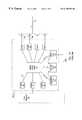
- a fiber-based access system intended to provide FTTCab, FTTC or FTTB as part of a communications networkconsists of two main types of components, an HDT 1 and a plurality of ONUs 2 (only one of which is shown).
- Each ONU 2has a plurality of Line Interface Units (LIUs) 3 , 27 connected to a bidirectional optical fiber distribution cable 4 via an intervening mux (multiplexer-demultiplexer) 5 , a PON out station (PON-OS) 28 , and an optical transceiver 6 .
- LIUsLine Interface Units
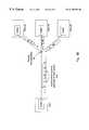
- a number of different ONUs in the same vicinityare grouped together by virtue of their associated distribution cables being joined together at a passive optical splitter 30 which is connected directly by means of an optical fiber umbilical 4 a to a transceiver 16 of the HDT 1 .
- Prior art configurations for the fiber link between the HDT and the multiple ONUsinclude the PON configuration shown in FIG. 1A, a point-to-point connection between the HDT and each ONU, as well as ring configurations with an optical transport ring passing from the HDT through each of the ONUs in turn and returning to the HDT.
- the HDT 1further comprises a digital switch matrix 17 connected to the transceivers 16 , in addition to an operations, administration and maintenance (OAM) processor 18 , a control processor 19 and a signalling processor 20 , each of which are also connected to the digital switch matrix 17 .
- the OAM processor 18includes a communication port 200 by which it can receive control, provisioning and configuration instructions from the management layer of the core network 23 as well as return the access system operational and maintenance status to the network management system.
- a plurality of transceiver blocks 21are connected between the switch matrix 17 and the core network 23 .
- each LIU 3is connected on one side by a bidirectional signal path 23 to the mux 5 and on the other side to a respective subscriber loop 7 which is commonly a copper twisted pair.
- the LIU 3performs the function of bidirectional communication of signals with the subscriber equipment in the appropriate analog format (e.g., 4 kHz voice for POTS, 2 B 1 Q line coded signals for ISDN—Integrated Service Digital Network) over the intervening twisted pair 7 ; the insertion of suitable loop currents by an Analog Front End (AFE) 8 ; and the superimposition of a ringing signal when required (and its rapid removal when the line conditions change to those of an “off-hook” phone) via a ringing generator 9 .
- the LIU 3includes a loop status detector 10 to detect when the phone or other service is activated (this may include detecting modem tones or changes in d.c. (direct current) or a.c. (alternating current) conditions on the loop 7 .
- the LIU 3usually includes a wideband digital one-bit delta-sigma oversampling codec 11 able to provide adequate bandwidth and quantizing noise performance when converting signals between the analog and digital domains, a decimator 12 D which removes some of the excess upstream bandwidth from the oversampling codec 11 , and an inverse decimator (or “interpolator”) 12 ID for converting downstream words into a high-rate bit stream.
- the multi-bit wordsare fed into (read from) a service-specific processor 14 implemented as a digital signal processing (DSP) engine which converts the upstream (downstream) oversampled and decimated data on the subscriber side 22 of the DSP 14 to (from) a standard format data stream on the core network side 23 of the DSP 14 .
- DSPdigital signal processing
- data arriving from the subscribermay be converted, in stages, from a 4 kHz analog POTS signal on the loop 7 into an analog voice waveform (free of d.c. loop signalling) at the output 24 of the AFE 8 , then into a 1 Mbps one-bit delta-sigma encoded bit stream at the output 25 of codec 11 , subsequently into 32 kHz ⁇ 20 bits/word linearly encoded samples at the output 22 of the decimator, and finally into an 8-bit ⁇ -law pulse code modulation (PCM) signal at the output 23 of DSP 14 .
- PCM⁇ -law pulse code modulation
- SASService-specific Service Application Software
- HDT 1a service-specific Service Application Software
- RAMservice-specific SAS Random Access Memory
- Each LIU 3interfaces with one physical path to one subscriber, such that if a subscriber has two twisted pair drops to the subscriber's premises, then two LIUs, and hence two DSPs, are required.
- a simple, fixed functional blocksuch as a ⁇ -law (or A-law) PCM codec or an ISDN 2 B 1 Q line driver/receiver and formatting block can be used.
- the LIU 3would take on a fixed function and it would be necessary to visit the remote site of the ONU to physically change the LIU type in order to change the services delivered. This is both costly and time-consuming because the LIU is usually located in a small cabinet in an outside-plant location, and technical staff have to find the location of the ONU and drive to it before they can physically change the appropriate LIU.
- An ONU 2is implemented by assembly of an array of LIUs 3 in a card cage (or its equivalent) along with additional circuit packs for common equipment such as the mux 5 , the PON-OS 28 , the optical transceiver 6 and an ONU control processor 26 which receives and transmits ONU control commands from and to the HDT 1 .
- the Loop Status Detector 10 and Loop Status Processor 13 of the LIU 3communicate loop-specific status and processing commands from the ONU control processor 26 to the ringing generator 9 . Not shown is a control link from the ONU control processor to the codec 11 for controlling its output and sampling rates.
- the mux 5may be implemented using time slots or packets. For this discussion, time division multiplexed (TDM) time slots will be assumed.
- TDMtime division multiplexed
- the mux 5has to accommodate differing final processed bandwidths on its signal paths 23 from each of the LIUs 3 and hence has to be programmable in bandwidth per port on its access (subscriber) side. For instance, a POTS circuit would occupy 64 kbps and hence would require one 8-bit word (time slot) every 125 ⁇ s (the standard frame period for TDM) for the information path.
- an ISDN circuitruns at 144 kbps, thus requiring three 8-bit time slots every 125 ⁇ s.
- a form of signalling and control path between the HDT and ONUis required. This can be achieved in one of many known forms, such as common channel signalling with multiplexed signalling messages from all line cards flowing in a single signalling channel, channel associated signalling or even embedded tone signalling or bit-robbing.
- the fiber optic links 4 , 4 asupport a bidirectional transmission path over one or two fibers. Either two fibers with unidirectional operation of each fiber could be used, or alternatively optical signals could be propagated in both directions down a single fiber with optical carriers being of a different wavelength in each direction.
- each ONU # 3consists of an ONU address synchronisation field, a control field, a common channel multiplexed signalling field and a traffic field comprising T eight-bit time slots for the transmission of data.
- the traffic, signalling and control fieldsare multiplexed in one of many well known ways.
- One methodis to allocate several time slots to the address field, then the first of two timeslots after the address field to a signalling channel and the other to a control channel.
- the signalling channelcarries loop status information and instructions to and from a specific line card interface in a multiplexed format (e.g. Common Channel Signalling or Multiplexed Channel-Associated Signalling).
- the control channelcarries ONU control information including SAS downloads as well as OAM status information.
- the remainder of the payload time slotsare used for multiplexed traffic data, which is in one or more 64 kb/s, 8-bit bytes (assuming a conventional 125 ⁇ s frame rate).
- Each service payloadis in its final format as required at the access/core network interface.
- POTSoccupies 1 time slot
- ISDNtakes up 3 time slots
- DS- 1occupies 25 timeslots
- each ONUtransmits a burst of data, timed so that, when combined by the splitter 30 , the bursts of data from all the ONUs form a train of incoming bursts at the HDT end as shown in FIG. 2 B.
- the transmission protocoloperates in TDM mode with HDT synchronization of ONU burst timing to avoid burst collision, which would otherwise result in one ONU overwriting another ONU's data in the upstream path. In this way, transmission path delay from each ONU can be measured. Pairs of upstream bursts on the umbilical are separated by “guard bands” to allow tolerance on the burst control loop.
- the structure of the individual subframes travelling in either directionis the same, although the inter-subframe assembly methods are different.
- the switch matrix 17accepts TDM frames from transceiver 16 and, according to a mapping controlled by the control processor 19 , routes the individual time slots in each frame towards the appropriate transceiver 21 . Similarly, the switch matrix 17 accepts downstream data from the transceivers 21 , subdivides the data into traffic time slots that constitute a particular subframe that is routed to the appropriate ONU.
- This switch “fabric”also acts as a conduit to connect ONU signalling and control paths to the signalling, control and OAM processors 20 , 19 , 18 .
- the signalling processor 20formats the signals from the ONUs into a standard protocol (e.g., TR- 303 ) to feed the network interfaces 21 (and vice versa), and formats the signalling messages to pass on subscriber-generated and access-generated messages to the core network 23 (and vice versa).
- TR- 303a standard protocol
- the signalling processor 20formats the signals from the ONUs into a standard protocol (e.g., TR- 303 ) to feed the network interfaces 21 (and vice versa), and formats the signalling messages to pass on subscriber-generated and access-generated messages to the core network 23 (and vice versa).
- the control processor 19controls the overall operation of the HDT and subtending ONUS, based on system status inputs and inputs from the OAM processor 18 and signalling processor 20 . For instance, the control processor 19 will manage the cross-connection map for the HDT switch matrix 17 .
- ONU 2is responsible for producing an analog version of an oversampled digital signal based on a received downstream flow of, say, mu-law-encoded voice data. Similarly, the ONU 2 oversamples its subscriber input and formats it for upstream use by the HDT 1 .
- the benefit of this techniquelies in the bandwidth savings achieved by transmitting fully formatted data across the PON.
- the complexity of such ONUsleads to the previously discussed disadvantages in the areas of cost, size, software download complexity, initial servicing and efficiency.
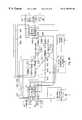
- an inventive fiber-based access system intended to provide FITLcomprises an HDT 101 and a plurality of ONUs 102 (only one of which is shown).
- Each ONU 102consists of an array of LIUs 103 , 127 along with a bidirectional mux 105 , an ONU control processor 126 , as well as a PON-OS 128 and an optoelectronic transceiver 6 .
- the mux 105is of the TDM type, comprising ports that are programmable so as to allot a selectable number of time slots (and hence, bandwidth) to each LIU in both directions of communication.
- the mux 105is connected to an oversampling codec 111 in each LIU 103 by a downstream line 153 and an upstream line 125 .
- the codec 111preferably comprises complementary one-bit sigma-delta analog-to-digital and digital-to-analog converters, and is connected to a wideband AFE, which interfaces directly with an analog drop line 7 leading to and from a subscriber.
- the link from the fiber at the curb to the subscriberis formed by copper twisted pairs, although coaxial cable may be accommodated by the use of a suitable AFE 8 .
- Each LIUfurther comprises a ringing generator 9 and a loop status detector 10 , which are connected to each other by line 147 , to the AFE 8 by respective lines 145 , 146 and to the mux by respective lines 133 , 134 .
- the ringing generator 9adds a ringing signal to the line under control from signal 133 received from the mux 105 , and removes it when the loop status detector 10 determines that the line is in the off-hook position.
- the loop status detector 10also provides a digital rendition of the analog line voltage on signal 134 connected to the mux 105 . It is to be understood that the ringing generator 9 and loop status detector 10 may be connected directly to the control processor 126 instead of to the mux 105 . Moreover, the mux 105 may itself be connected to the ONU control processor 126 .
- the mux 105 and the PON-OS 128can be effected using a bidirectional link 135 or two unidirectional links.
- the ONU control processor 126is connected to the PON-OS 128 by a bidirectional signal link 123 .
- the transceiver 6serves to transform the (multiplexed) electronic data into an optical signal destined for the HDT, and to convert an optical signal from the HDT into electronic data used by the mux 105 .
- the optical signals in both directionspreferably originate from, and are combined onto, a single fiber optic cable 4 .
- optical fiberscome together at a passive optical splitter 30 , which in the upstream direction adds the optical energy on each fiber and sends the resultant signal along an umbilical link 4 a to the HDT, and in the downstream direction splits the downstream optical signal on the fiber umbilical 4 a into a number of identical optical signals a travelling along respective individual fibers 4 .
- the HDTinterfaces with the umbilicals ( 4 a as well as others not shown) by means of respective optoelectronic transceivers 16 connected to a digital switch matrix 117 .
- the switch matrixis a conventional TDM digital switch with traffic data entered into sequential locations in a large data memory at a given fixed frame rate, and the same data read out again in a sequence controlled by a connection memory.
- the sequencingis controlled via a control link (not shown) by a control processor 119 in the HDT.
- the control processor 119is preferably also connected to a loop status processor 113 , which performs functions such as decoding a telephone number dialled by the subscriber based on the sampled digital line voltage transmitted from the loop status detector 10 in each LIU 103 .
- the HDT 101further comprises a second switch matrix 131 , also a conventional TDM digital switch controlled by the control processor 119 , which is connected to a plurality of transceivers 21 that interface with the core network (not shown). Also connected to switch matrix 131 are a signalling processor 20 and an OAM processor 118 . As in the prior art, the signalling processor 20 formats outgoing data so that it is in the proper signalling format (e.g., TR- 303 ) used by the core network, and vice versa.
- the OAM processor 118provides the core network with status information via a link 200 ; this link also serves to relay instructions for configuring the mux 105 in the ONUs 102 .
- the control processorcontrols the overall operation of the HDT and subtending ONUs, based on inputs from the OAM processor 118 and the signalling processor 20 , as well as system status inputs.
- the switch matrices 117 , 131are connected by a bidirectional “hair pin” connection 132 and also through sets of DSPs. The connections are shown in greater detail in FIG. 4 B.
- the first bank of processorsconsists of a plurality of DSPs 114 X, Y, Z that process respective demultiplexed upstream signals 160 X, Y, Z and produce respective signals 170 X, Y, Z that are routed by switch matrix 131 .
- Decimators 130 X, Y, Zrespectively intercept the upstream signals 160 X, Y, Z so that the associated DSPs are fed fixed-length words of data at a certain speed instead of an oversampled bit stream at a higher rate, as output by the codec in a given LIU.
- the second set of processors joining the switch matrices 117 , 131is a plurality of DSPs 114 A, B, C which process signals 161 A, B, C arriving from switch matrix 131 , forming signals 163 A, B, C.
- the DSPs 114 A, B, Care connected to respective interpolators 129 A, B, C, which create respective high-rate bit streams 164 A, B, C that are routed by switch matrix 117 .
- Each DSP 114 X, Y, Z and 114 A, B, Cis preprogrammed by application and data files stored in respective SAS RAMs 115 X, Y, Z and 115 A, B, C to execute a conversion algorithm that converts digital data from one format to another.
- the actual number of DSPs, decimators and interpolators requiredwill depend on total system requirements.
- the hair pin connection 132serves to interconnect the two switch matrices 117 , 131 , should it be necessary to implement a complex conversion algorithm involving multiple processing steps executed by traversing the DSPs several times in sequence.
- the structure of the inventive systemdiffers from that of the prior art in that the ONUs have been simplified by migrating the DSP functionality to the HDT.
- the ONUsinstead of transmitting fully formatted data across the PON, only “raw” (unformatted) data at high bit rates is exchanged between the HDT 101 and ONU 102 (and others not shown) along the fibers 4 , 4 a .
- the high data rates requiredare easily achievable using commonly available optical fibers.
- FIG. 3Aillustrates how a downstream frame F of 125/M ⁇ s (microseconds) is divided into subframes SF 1 -SF 5 destined for respective ONUs.
- the value of 125 ⁇ sis the standard length of a frame in the public switched telephone network (PSTN) and M is the factor by which this frame length is reduced, usually 1, 8, 12, 16, 24, 25 or 32.
- PSTNpublic switched telephone network
- Mis used in determining the so-called bandwidth granularity (BG), which is a measure of the resolution in bandwidth deliverable across the PON.
- BGbandwidth granularity
- the relative size of a subframemay differ from one ONU to another.
- a particular subframe SF 3it is shown as divided into four fields: an ONU address and synchronization field, a control field, a signalling field and a traffic field.
- the address, control, signalling and traffic fieldsare preferably time slots populated with bits and dedicated to transmitting certain classes of information from the HDT to the ONU.
- the address field in each subframeidentifies the ONU for which the traffic is destined.
- the signalling fieldpreferably carries instructions (such as ringing generator control) to a specific LIU in a known multiplexed format.
- the control fieldprovides OAM status information and instructions to configure the mux 105 , thereby to allocate a certain bandwidth to each LIU according to the service-dependent bandwidth needs for that LIU.
- the control channel in the downstream subframesalso provides control of the codec sampling and output rates in each LIU, as well as precise timing instructions for the transmittal of bursts of upstream data.
- the traffic fieldis divided into a multitude of (in this case, twenty-nine) time slots T 1 -T 29 of “P” bits each.
- the BGcan be defined as the bandwidth offered by the transmission of one time slot per frame, and is dependent on the number of bits per time slot (“P”) and on the above-identified frame size reduction factor (“M”). In mathematical terms,
- the traffic time slotsare arranged into a known number (in this case, fifteen) of groups G 1 -G 15 , each group providing downstream data to a respective LIU.
- the number of time slots required per groupis selectable and will depend on the bandwidth granularity and on the type of service provided.
- the mux 105forms a subframe that is subdivided into groups of time slots, whereby a group is associated with a specific LIU and is allotted a number of time slots that is dependent on the BG and on the required upstream bandwidth.
- an ONUUpon command from the HDT, an ONU transmits its fully constructed upstream subframe on a once-per-frame basis, although the subframes arriving from various ONUs are not contiguous, but instead arrive separated by guard bands.
- Scenario Adeals with the situation in which the core network sends and receives multiplexed channels of 8-bit mu-law PCM voice data that are connected through the HDT and ONUs to analog subscriber loops that send and receive analog POTS signals.
- Scenario Btreats the situation in which a Frame Relay (or similar packetized) service carried across an ATM core network is delivered to and from an end user as a Frame Relay service over a DS- 1 (1.544 Mbps) twisted pair link.
- switch matrix 131routes the multiplexed channels of 8-bit mu-law encoded voice samples (arriving in a standard network format) to DSP 114 A after reformatting is done by the signalling processor 20 .
- DSP 114 Ais dedicated to producing a stream 163 A of, say, 20-bit linearly encoded samples at 32 kHz from the 8-bit mu-law encoded data. In the prior art, this exact same function would be performed by a dedicated DSP within each destination LIU.
- DSP 114 A in the present inventionprocesses multiple channels destined for corresponding LIUs, and is thus effectively shared by a number of different LIUs.
- the data stream 163 Apasses through interpolator 129 A so as to enter switch matrix 117 as a high-rate bit stream 164 A, typically on the order of 1 Mbps per channel.
- This datais in a generic data format, as it simply requires digital-to-analog conversion by the codec in the destination LIU.
- Switch matrix 117also accepts the other high rate data streams 164 B, C produced by the respective DSPs 114 B, C, and arranges the data into groups, subframes and frames according to destination LIU, ONU and PON in the manner described earlier.
- the optical downstream signal exiting the HDTwhich may have a data rate on the order of several hundred Mbps, is converted to electronic format by the transceiver 6 and subsequently fed to the PON-OS 128 .
- the address field in each subframeis checked in order to determine whether the current ONU is the intended recipient of that subframe. Only the subframes intended for that particular ONU are output on link 135 to the mux 105 .
- the mux 105outputs, by a process of demultiplexing, the proper traffic time slots on the link 153 to the codec 111 , along with control information for the ringing generator 9 on link 133 .
- the PON-OS 128provides control information to the ONU control processor 126 via link 123 ; alternatively, this information may be delivered from the mux 105 .
- the codec 111then converts the high-rate bit stream on its network-side link 153 into an analog POTS waveform, and the AFE 8 adds appropriate ringing voltages and loop currents.
- the AFEis also responsible for removing the ringing voltage when an off-hook condition is detected, and may interface to a variety of loop termination media, such as copper twisted pair or coaxial cable.
- the AFE 8will prepare the analog POTS signal for sampling by the oversampling codec 111 at around 1 MHz.
- the oversampled data 152is fed to the mux 105 , where a suitable number of time slots in a subframe are allotted to this stream.
- the mux 105will partially fill the control and signalling fields with the status of the analog line received from the loop status detector 10 via path 134 .
- the address fieldwill indicate the source ONU.
- the mux 105then assembles the time slots from each LIU, as well as all of the information in the remaining fields, forming a subframe, and sends it to the PON-OS 128 .
- the PON-OSwaits for the go-ahead from the ONU control processor 126 before sending the subframe onto the fiber 4 via the transceiver 6 .
- the ONU control processor 126receives this timing information from the HDT in the control field of the downstream subframes.
- Each ONU sharing the same fiber umbilical 4 ais cyclically instructed to send its burst of data, resulting in a “train” 400 of subframes SF 1 - 3 as shown in FIG. 3 B. Any consecutive pair of bursts is separated by a short time span 402 of variable length during which no transmission occurs, called a guard band. This is designed to account for the delay in instructing one ONU to transmit while ensuring that the previous ONU has ceased transmission.
- the train 400 of data containing the oversampled POTS signal of upstream scenario Aarrives at switch matrix 117 of the HDT 101 through transceiver 16 .
- the corresponding traffic time slotsare extracted and routed via decimator 130 X to a DSP 114 X which converts the oversampled decimated data arriving from the subscriber to 8-bit mu-law data.
- DSP 114 Xwill likely be assigned the task of converting multiple upstream data channels from oversampled decimated format into mu-law format.
- the output 170 X of DSP 114 Xsubsequently passes through switch matrix 131 , where it is routed towards its possibly multiple destinations elsewhere in the network via transceivers 21 .
- the signalling processor 20appropriately formats the outgoing signals prior to optoelectronic conversion by transceivers 21 .
- DSP 114 Bis dedicated to the process of reassembling segments of Frame Relay packets contained in the ATM cell stream into pure Frame Relay packets.
- This reassembly portion of a so-called segmentation and reassembly (SAR) processis achieved by removing the ATM Gus envelope around the Frame Relay packet segments in the payload of each ATM cell and reassembling those segments into Frame Relay packets.
- SARsegmentation and reassembly
- DSP 114 Bis still not in a suitable format for delivery to the customer (who is expecting to receive line coded 1.544 Mbps DS- 1 data). Therefore, the output 163 B of DSP 114 B is rerouted to the input of another DSP processor 114 C by switch matrix 117 , hair pin connection 132 and switch matrix 131 .
- DSP 114 Cis empowered with the insertion of Frame Relay packets into the payload of a 1.544 Mbps DS- 1 .
- DSP 114 Calso formats the digital signal with the required line code, yielding data stream 163 C.
- Data stream 163 Cis subsequently passed through an interpolator 129 C to yield a very high rate oversampled bit stream 164 C, having a data rate on the order of 20 Mbps and requiring, for example, 40 time slots at a bandwidth granularity of 512 kbps per slot.
- the bit stream 164 Cis multiplexed by switch matrix 117 and delivered to the appropriate codec 111 of the destination ONU in the manner described above.
- the oversampled line coded DS- 1 datais converted into an analog waveform, although the data per se is still in digital format, being encoded in the various voltage level durations and changes characteristic to the line code in use.
- bit stream 164 C in this downstream scenario Bis in the same universal oversampled format as bit stream 164 A previously considered in downstream scenario A (although its rate is higher).
- bit stream 164 Apreviously considered in downstream scenario A (although its rate is higher).
- the commonness of the data format communicated between the HDT and the ONUs (and vice versa)is an important property of the present invention.
- the rateson the other hand, will depend on the service being offered, and the output or sampling rate of the codecs can be controlled via the downstream control channel, as previously discussed.
- upstream scenario Bthe digital DS- 1 signal sent by the subscriber along the loop 7 undergoes frequency selective loss, accumulates noise and suffers from other impairments as it is propagated along the twisted pair drop.
- the subscriber-emitted signalreaches the AFE 8 .
- regenerationis required to recover the original digital data from the distorted analog waveform.
- this regenerationis performed in the LIU proper.
- the codec 111 in the inventive systemsimply oversamples the data at around 20 MHz as if it were a wideband analog input signal. In other words, the codec 111 “blindly” oversamples the signal and performs no data recovery, leaving the data in the common, high-bandwidth digital format.
- the mux 105inserts the oversampled bit stream into the time slots preassigned to that LIU, subsequently creating a subframe which is sent to the HDT via the PON-OS 128 and transceiver 6 using the upstream burst transmission procedure described above.
- the inventive systemtrades bandwidth efficiency for simplicity of operation and economy of construction.
- oversampled DS- 1 dataarrives at a transceiver 16 , and is subsequently routed to a first DSP 114 Y which is programmed to recover the 1.544 Mbps bit stream from the oversampled version of the distorted line coded signal.
- This known regeneration processis achieved by a combination of frequency equalization, noise filtering and the application of a clocked decision threshold.
- the output 170 Y of DSP 114 Yis then routed to the input of a second DSP 114 Z via switch matrix 131 , hairpin connection 132 and switch matrix 117 .
- the second DSP 114 Zremoves the DS- 1 header and plainly outputs the payload in the form of Frame Relay packets which had been contained in the original DS- 1 stream.
- the output 170 Z of DSP 114 Zis once again “hair pinned” back to a third DSP (not shown) which segments the Frame Relay packets into ATM cells by applying the segmentation portion of the SAR process described above.
- the ATM datais ready to be sent to its destination through switch matrix 131 and a transceiver 21 . Analogous to interpolation in the downstream case, decimation performed in the HDT occurs only once, i.e., at the input to the first DSP in line for processing subscriber-generated data.
- switch matrix 117is sized to carry the aggregate of all the oversampled data to and from the ONUs in addition to all of the data that is “hair pinned”, resulting in the requirement for a much larger data memory when using a standard 125- ⁇ s frame length.
- frame lengthis shortened to match the larger channel bandwidths of the oversampled signals, the memory requirement is reduced since less data arrives per frame.
- the value of M discussed abovecan thus be chosen to alleviate the requirements on switch matrix 117 by setting a convenient operating frame rate.
- the digital switch matrix 131has somewhat lesser requirements in that it handles data exiting the DSPs in a finalized format while also handling higher-bandwidth data “hair-pinned” back to the access side switch matrix 117 . However, no data need travel through switch matrix 131 in non-decimated form. Switch matrix 131 would thus be chosen as having a frame rate of standard length, i.e., 125 ⁇ s. Alternatively, several switches may be concatenated in the case where a high amount of “hair-pinning” is expected, one switch operating, for example, on a short frame with another one operating on a 125- ⁇ s frame.
- the HDTneed concern itself with total DSP processing power, but not with a particular number of DSPs.
- the DSPsthemselves may offer varying degrees of processing ability, and need not be sized to accommodate the worst-case scenario of data conversion, as was formerly the case.
- a total of 218 LIUscan be accommodated by a mere 16 DSPs sized to handle DS- 1 -to-POTS conversion. This is minute compared to the 218 DSPs of at least the same power (i.e., not counting combinations of services) that would be required in a prior art approach based on service-independent line cards.
- the analysismay be extended one step further by applying known practical traffic mix requirement limits into the process of dimensioning the DSPs. For instance, if only a certain maximum percentage (e.g., 10%) of lines will ever need DS- 1 service and another maximum percentage of lines (e.g., 25%) will ever need ISDN service at one time (without knowing which lines are occupied by what service), then the above inequality becomes
- a further advantage of the present inventionis that the DSPs are found in a centralized environment, which reduces the cost of provisioning and dimensioning the DSPs to meet future traffic demands. Moreover, the DSPs are flexible and their respective RAMs are reprogrammable by the control processor 119 , either through a control bus 183 as illustrated in FIG. 4B or through one of the switch matrices 117 , 131 , thereby providing the ability to track the evolving demands of the network.
- the control processor 119 in the HDTcan also play a vital role in reducing the bandwidth taken up by the various LIUs, particularly in the case of ISDN and DS- 1 services. For instance, an on-hook (unused) POTS line takes up very little a bandwidth, as does an unused DS- 1 video conference line (i.e., the far end modem at the customer premises is in a quiescent mode), since the only requirement on that DS- 1 loop is to detect the start up of the DS- 1 Customer Premises Equipment.
- the control processor 119can thus lower the sampling and output rates of the oversampling codecs and decimators on LIUs which are in an on-hook or quiescent condition to values much below that which the LIUs would require for an active delivery of POTS or DS- 1 services.
- a single fiber umbilicalcan thus serve a distribution area with over 600 customers, which is the norm for current North American telecommunications company serving areas.
- decimated dataare transmitted across the PON.
- decimation and inverse functionsare kept in the LIUs.
- a decimatorwould be placed between the codec 111 and the mux 105 instead of in the HDT.
- decimatorscould be placed in both locations, whereby each upstream signal path would comprise one fully functional decimator and another operating in bypass mode.
- analogous arrangementsapply to the interpolators in the downstream path.
- the functionality of the loop status processor 113would be placed in each LIU 103 , 127 .
- the loop status detector 10may feed its signal 134 directly to the ONU control processor 126 or to an intermediate loop status processing block.
- the ONU control processorwould perform the control functions of determining the condition of the line or decoding the dialled digits, relaying this information to the HDT via the upstream control channel.
- the ringing generator 9may be controlled from the ONU control processor 126 , thus further liberating the mux 105 , which is left with the task of simply routing the data to and from the LIUs.
- FIG. 4Awherein a single high-capacity switch matrix 195 replaces the switch matrices 117 , 131 of FIG. 4 B.
- hair pinningdoes not require a link external to the switch matrix. Instead, data both from the ONUs and from the core network are continuously routed to the DSP bank and back through the switch matrix 195 until the required number of processing operations have been performed.
- the HDTis identical to that of FIG. 4 B.
- FIG. 4CYet another example of an inventive HDT partitions the short-frame switch matrices of FIG. 4B into two, resulting in four STS switches 117 U, 117 D, 131 U, 131 D as shown in FIG. 4 C.
- two hair pin connections 132 U, 132 Dare required, one for each direction travelled by the data.
- the signalling processor 20now provides independent grooming of the frames in both the downstream and upstream paths.
- FIG. 4Cthere is no fundamental difference in operation of the embodiment illustrated in FIG. 4C with respect to what has already been described with reference to FIG. 4 B.
Landscapes
- Engineering & Computer Science (AREA)
- Computer Networks & Wireless Communication (AREA)
- Small-Scale Networks (AREA)
- Data Exchanges In Wide-Area Networks (AREA)
Abstract
Description
| Oversampled | Oversampled and Decimated Bit | |
| Service | Bit Rate | Rate |
| POTS | 1-2 Mbps | 32 kHz × 20 bits/word = 640 kbps |
| Foreign | 1-2 Mbps | 32 kHz × 20 bits/word = 640 kbps |
| Exchange | ||
| ISDN | 2-10 Mbps | 160 kHz × 10 bits/word = 1.6 Mbps |
| DS-1 | 20-40 Mbps | 1.5 MHZ × 10 bits/word = 15 Mbps |
| 8 DSPs × 24 POTS lines/DSP → 192 POTS LIUs serviced | ||
| 4 DSPs × 6 ISDN lines/DSP → 24 ISDN LIUs serviced | ||
| 2 DSP × 1 DS-1 lines/DSP → 2 DS-1 LIUs serviced | ||
| [(640 kbps * 25%) + (0,2 * 640 kbps * 75%)] | * 80% | |||
| + | [(1.6 Mbps * 100%)] | * 10% | ||
| + | [(15 Mbps * 25%) + (0.2 * 15 Mbps * 75%)] | * 10% | ||
| = | 964.8 kbps per loop | |||
Claims (57)
Priority Applications (5)
| Application Number | Priority Date | Filing Date | Title |
|---|---|---|---|
| US09/056,096US6198558B1 (en) | 1998-04-07 | 1998-04-07 | Architecture repartitioning to simplify outside-plant component of fiber-based access system |
| CA002268589ACA2268589A1 (en) | 1998-04-07 | 1999-04-06 | Architecture repartitioning to simplify outside-plant component of fiber-based access system |
| EP99302713AEP0949838B1 (en) | 1998-04-07 | 1999-04-07 | Architecture repartitioning to simplify outside-plant component of fibre-based access system |
| DE69917975TDE69917975T2 (en) | 1998-04-07 | 1999-04-07 | Distributed architecture to simplify the external installation of an access system based on optical fibers |
| US09/756,739US6421150B2 (en) | 1998-04-07 | 2001-01-10 | Architecture repartitioning to simplify outside-plant component of fiber-based access system |
Applications Claiming Priority (1)
| Application Number | Priority Date | Filing Date | Title |
|---|---|---|---|
| US09/056,096US6198558B1 (en) | 1998-04-07 | 1998-04-07 | Architecture repartitioning to simplify outside-plant component of fiber-based access system |
Related Child Applications (1)
| Application Number | Title | Priority Date | Filing Date |
|---|---|---|---|
| US09/756,739DivisionUS6421150B2 (en) | 1998-04-07 | 2001-01-10 | Architecture repartitioning to simplify outside-plant component of fiber-based access system |
Publications (1)
| Publication Number | Publication Date |
|---|---|
| US6198558B1true US6198558B1 (en) | 2001-03-06 |
Family
ID=22002123
Family Applications (2)
| Application Number | Title | Priority Date | Filing Date |
|---|---|---|---|
| US09/056,096Expired - LifetimeUS6198558B1 (en) | 1998-04-07 | 1998-04-07 | Architecture repartitioning to simplify outside-plant component of fiber-based access system |
| US09/756,739Expired - LifetimeUS6421150B2 (en) | 1998-04-07 | 2001-01-10 | Architecture repartitioning to simplify outside-plant component of fiber-based access system |
Family Applications After (1)
| Application Number | Title | Priority Date | Filing Date |
|---|---|---|---|
| US09/756,739Expired - LifetimeUS6421150B2 (en) | 1998-04-07 | 2001-01-10 | Architecture repartitioning to simplify outside-plant component of fiber-based access system |
Country Status (4)
| Country | Link |
|---|---|
| US (2) | US6198558B1 (en) |
| EP (1) | EP0949838B1 (en) |
| CA (1) | CA2268589A1 (en) |
| DE (1) | DE69917975T2 (en) |
Cited By (61)
| Publication number | Priority date | Publication date | Assignee | Title |
|---|---|---|---|---|
| US20020030875A1 (en)* | 2000-07-31 | 2002-03-14 | Jin-Hee Kim | Method for requesting grant for MAC protocol in PON |
| WO2002045308A1 (en)* | 2000-11-17 | 2002-06-06 | Alloptic, Inc. | Point-to-multipoint passive optical network that utilizes variable-length packets |
| US6498667B1 (en)* | 1999-09-10 | 2002-12-24 | Quantum Bridge Communications, Inc. | Method and system for packet transmission over passive optical network |
| US20020196499A1 (en)* | 2001-06-25 | 2002-12-26 | Jeroen Wellen | Method and system for multiplexed optical information transport |
| WO2003009497A1 (en)* | 2001-07-20 | 2003-01-30 | Wenbin Jiang | High-speed optical data links |
| US6532218B1 (en)* | 1999-04-05 | 2003-03-11 | Siemens Information & Communication Networks, Inc. | System and method for multimedia collaborative conferencing |
| US20030053170A1 (en)* | 2001-09-17 | 2003-03-20 | Levinson Frank H. | Optoelectronic device capable of participating in in-band traffic |
| US20030081289A1 (en)* | 2001-09-28 | 2003-05-01 | Hirotaka Oomori | Light-emitting module |
| WO2002097476A3 (en)* | 2000-11-17 | 2003-05-01 | Alloptic Inc | Point-to-multipoint passive optical network that utilizes variable-length packets and variable-length upstream tine slots |
| US20030099245A1 (en)* | 2001-11-29 | 2003-05-29 | Yong-Hoe Kim | Host digital terminal |
| US6650696B1 (en)* | 1999-12-15 | 2003-11-18 | Cisco Technology, Inc. | System and method for communicating data among a plurality of digital signal processors |
| US20040008927A1 (en)* | 2002-07-15 | 2004-01-15 | Kowalkowski Anthony S. | Pluggable optical transceiver array having wavelength division multiplexing and demultiplexing features |
| US6704545B1 (en)* | 2000-07-19 | 2004-03-09 | Adc Telecommunications, Inc. | Point-to-multipoint digital radio frequency transport |
| US6718553B2 (en) | 2001-06-06 | 2004-04-06 | Complete Tv Llc | Centralized aggregation of broadcast television programming and multi-market digital delivery thereof over interconnected terrestrial fiber optic networks |
| US6721797B1 (en)* | 2000-05-16 | 2004-04-13 | Lucent Technologies Inc. | Partial back pressure (PBP) transmission technique for ATM-PON using rate controllers to reduce a maximum output rate from a peak rate to a controlled rate |
| US20040071389A1 (en)* | 2002-09-13 | 2004-04-15 | Hofmeister Rudolf J. | Optical and electrical channel feedback in optical transceiver module |
| US20040076119A1 (en)* | 2002-06-25 | 2004-04-22 | Aronson Lewis B. | Transceiver module and integrated circuit with dual eye openers and integrated loopback and bit error rate testing |
| US20040091005A1 (en)* | 2002-11-08 | 2004-05-13 | Hofmeister Ruldolf J. | Temperature and jitter compensation controller circuit and method for fiber optics device |
| US20040102144A1 (en)* | 2001-07-25 | 2004-05-27 | Brown Nathan R. | Polishing systems for use with semiconductor substrates including differential pressure application apparatus |
| US20050089281A1 (en)* | 2003-06-20 | 2005-04-28 | Chia-Hung Chiu | Optical transceiver module |
| US20050111501A1 (en)* | 2002-02-12 | 2005-05-26 | Yew-Tai Chieng | Systems, devices and methods for temperature-based control of laser performance |
| US20050111845A1 (en)* | 2002-06-25 | 2005-05-26 | Stephen Nelson | Apparatus, system and methods for modifying operating characteristics of optoelectronic devices |
| US20050127402A1 (en)* | 2003-12-15 | 2005-06-16 | Dybsetter Gerald L. | Configurable input/output terminals |
| US20050169585A1 (en)* | 2002-06-25 | 2005-08-04 | Aronson Lewis B. | XFP transceiver with 8.5G CDR bypass |
| US20050226618A1 (en)* | 2000-12-11 | 2005-10-13 | Harris Corporation | Network transceiver for extending the bandwidth of optical fiber-based network infrastructure |
| US20050232635A1 (en)* | 2004-04-14 | 2005-10-20 | Finisar Corporation | Network data transmission and diagnostic methods using out-of-band data |
| US20060002712A1 (en)* | 2004-07-02 | 2006-01-05 | Finisar Corporation | Calibration of digital diagnostics information in an optical transceiver prior to reporting to host |
| US20060002711A1 (en)* | 2004-07-02 | 2006-01-05 | Finisar Corporation | Filtering digital diagnostics information in an optical transceiver prior to reporting to host |
| US20060259596A1 (en)* | 1999-10-18 | 2006-11-16 | Birse Cameron S | Method and apparatus for administering the operating system of a net-booted environment |
| US20070064688A1 (en)* | 2003-06-26 | 2007-03-22 | Stefano Prettegiani | Switching network |
| US20070077069A1 (en)* | 2000-10-04 | 2007-04-05 | Farmer James O | System and method for communicating optical signals upstream and downstream between a data service provider and subscribers |
| US7230961B2 (en) | 2002-11-08 | 2007-06-12 | Finisar Corporation | Temperature and jitter compensation controller circuit and method for fiber optics device |
| US20070183779A1 (en)* | 2006-02-03 | 2007-08-09 | Martin Bouda | System and Method for Extending Reach in a Passive Optical Network |
| US7277727B1 (en)* | 2000-11-22 | 2007-10-02 | Sprint Communications Company L.P. | System and method for processing a signal |
| US20070248359A1 (en)* | 2006-04-25 | 2007-10-25 | Jean-Luc Pamart | Multiport optical transceiver |
| US20070264009A1 (en)* | 2006-04-28 | 2007-11-15 | Adc Telecommunications, Inc. | Systems and methods of optical path protection for distributed antenna systems |
| US7301933B1 (en)* | 2000-12-22 | 2007-11-27 | Cisco Technology, Inc. | Delivery of a service program to a digital signal processor within a multiservice processing system |
| US20070292133A1 (en)* | 2002-05-20 | 2007-12-20 | Whittlesey Paul F | System and method for communicating optical signals to multiple subscribers having various bandwidth demands connected to the same optical waveguide |
| US20080014948A1 (en)* | 2006-07-14 | 2008-01-17 | Lgc Wireless, Inc. | System for and method of for providing dedicated capacity in a cellular network |
| US20080037430A1 (en)* | 2006-08-11 | 2008-02-14 | Santera Systems, Inc. | Methods, systems, and computer program products for hairpin condition elimination in a telecommunications network |
| US20080085117A1 (en)* | 2004-08-19 | 2008-04-10 | Farmer James O | System and method for communicating optical signals between a data service provider and subscribers |
| US7437079B1 (en) | 2002-06-25 | 2008-10-14 | Finisar Corporation | Automatic selection of data rate for optoelectronic devices |
| US7532820B2 (en) | 2004-10-29 | 2009-05-12 | Finisar Corporation | Systems and methods for providing diagnostic information using EDC transceivers |
| US20090176448A1 (en)* | 2002-02-25 | 2009-07-09 | Adc Telecommunications, Inc. | Distributed automatic gain control system |
| US7561855B2 (en) | 2002-06-25 | 2009-07-14 | Finisar Corporation | Transceiver module and integrated circuit with clock and data recovery clock diplexing |
| US7599711B2 (en) | 2006-04-12 | 2009-10-06 | Adc Telecommunications, Inc. | Systems and methods for analog transport of RF voice/data communications |
| US7774774B1 (en)* | 2003-10-22 | 2010-08-10 | Apple Inc. | Software setup system |
| US20100241728A1 (en)* | 2002-10-01 | 2010-09-23 | Gordon Ross Meyer | Method and apparatus for dynamically locating resources |
| US7817958B2 (en) | 2006-12-22 | 2010-10-19 | Lgc Wireless Inc. | System for and method of providing remote coverage area for wireless communications |
| US7848770B2 (en) | 2006-08-29 | 2010-12-07 | Lgc Wireless, Inc. | Distributed antenna communications system and methods of implementing thereof |
| US8005050B2 (en) | 2007-03-23 | 2011-08-23 | Lgc Wireless, Inc. | Localization of a mobile device in distributed antenna communications system |
| US8010116B2 (en) | 2007-06-26 | 2011-08-30 | Lgc Wireless, Inc. | Distributed antenna communications system |
| US20120057877A1 (en)* | 2003-03-14 | 2012-03-08 | Enablence Usa Fttx Networks Inc. | Method and system for providing a return path for signals generated by legacy terminals in an optical network |
| US8583100B2 (en) | 2007-01-25 | 2013-11-12 | Adc Telecommunications, Inc. | Distributed remote base station system |
| US8737454B2 (en) | 2007-01-25 | 2014-05-27 | Adc Telecommunications, Inc. | Modular wireless communications platform |
| US8958789B2 (en) | 2002-12-03 | 2015-02-17 | Adc Telecommunications, Inc. | Distributed digital antenna system |
| US9001811B2 (en) | 2009-05-19 | 2015-04-07 | Adc Telecommunications, Inc. | Method of inserting CDMA beacon pilots in output of distributed remote antenna nodes |
| US9112547B2 (en) | 2007-08-31 | 2015-08-18 | Adc Telecommunications, Inc. | System for and method of configuring distributed antenna communications system |
| US9542172B2 (en) | 2013-02-05 | 2017-01-10 | Apple Inc. | Automatic updating of applications |
| US9577922B2 (en) | 2014-02-18 | 2017-02-21 | Commscope Technologies Llc | Selectively combining uplink signals in distributed antenna systems |
| US10499269B2 (en) | 2015-11-12 | 2019-12-03 | Commscope Technologies Llc | Systems and methods for assigning controlled nodes to channel interfaces of a controller |
Families Citing this family (34)
| Publication number | Priority date | Publication date | Assignee | Title |
|---|---|---|---|---|
| US6920156B1 (en)* | 1999-12-01 | 2005-07-19 | Cisco Technology, Inc. | Method and system for transporting synchronous and asynchronous traffic on a synchronous bus of a telecommunications node |
| KR100317124B1 (en)* | 1999-12-27 | 2001-12-24 | 오길록 | ONU Function Processing Apparatus in ATM-PON System |
| EP1354437A2 (en)* | 2000-10-26 | 2003-10-22 | Wave7 Optics, Inc. | Method and system for processing upstream packets of an optical network |
| DE10102144C2 (en)* | 2001-01-18 | 2003-02-13 | Infineon Technologies Ag | Broadband optical transmission device |
| US20060020975A1 (en)* | 2001-07-05 | 2006-01-26 | Wave7 Optics, Inc. | System and method for propagating satellite TV-band, cable TV-band, and data signals over an optical network |
| US7877014B2 (en) | 2001-07-05 | 2011-01-25 | Enablence Technologies Inc. | Method and system for providing a return path for signals generated by legacy video service terminals in an optical network |
| US20030072059A1 (en)* | 2001-07-05 | 2003-04-17 | Wave7 Optics, Inc. | System and method for securing a communication channel over an optical network |
| WO2003005611A2 (en)* | 2001-07-05 | 2003-01-16 | Wave7 Optics, Inc. | System and method for communicating optical signals to multiple subscribers having various bandwidth demands connected to the same optical waveguide |
| US7529485B2 (en) | 2001-07-05 | 2009-05-05 | Enablence Usa Fttx Networks, Inc. | Method and system for supporting multiple services with a subscriber optical interface located outside a subscriber's premises |
| US7593639B2 (en)* | 2001-08-03 | 2009-09-22 | Enablence Usa Fttx Networks Inc. | Method and system for providing a return path for signals generated by legacy terminals in an optical network |
| EP1309221A1 (en)* | 2001-11-02 | 2003-05-07 | Alcatel | System and method for delivering telecommunications services to customer premises |
| US6697374B1 (en)* | 2001-12-05 | 2004-02-24 | Flexlight Networks | Optical network communication system |
| US7038910B1 (en) | 2002-01-07 | 2006-05-02 | Wave7 Optics, Inc. | System and method for removing heat from a subscriber optical interface |
| US7583897B2 (en)* | 2002-01-08 | 2009-09-01 | Enablence Usa Fttx Networks Inc. | Optical network system and method for supporting upstream signals propagated according to a cable modem protocol |
| US20040126119A1 (en)* | 2002-08-20 | 2004-07-01 | Evangelides Stephen G. | Method and apparatus for providing a terminal independent interface between a terrestrial optical terminal and an undersea optical transmission path |
| US20040096214A1 (en)* | 2002-08-20 | 2004-05-20 | Red Sky Systems, Inc. | Method and apparatus for using optical idler tones for performance monitoring in a WDM optical transmission system |
| US20040096215A1 (en)* | 2002-08-20 | 2004-05-20 | Evangelides Stephen G. | Method and apparatus for performing system monitoring in a terminal independent interface located between a terrestrial optical terminal and an undersea optical transmission path |
| WO2004019074A2 (en)* | 2002-08-20 | 2004-03-04 | Red Sky Systems, Inc. | Method and apparatus for performing system monitoring in a terminal independent interface located between a terrestrial optical terminal and an undersea optical transmission path |
| US7058260B2 (en)* | 2002-10-15 | 2006-06-06 | Wave7 Optics, Inc. | Reflection suppression for an optical fiber |
| US8958697B2 (en)* | 2003-06-10 | 2015-02-17 | Alexander I. Soto | System and method for optical layer management in optical modules and remote control of optical modules |
| US20050232634A1 (en)* | 2004-03-29 | 2005-10-20 | Evangelides Stephen G Jr | Undersea optical transmission system employing low power consumption optical amplifiers |
| US20080050121A1 (en)* | 2004-06-17 | 2008-02-28 | Evangelides Stephen G | Submarine optical transmission systems having optical amplifiers of unitary design |
| WO2006020538A2 (en)* | 2004-08-10 | 2006-02-23 | Wave7 Optics, Inc. | Countermeasures for idle pattern srs interference in ethernet optical network systems |
| WO2006041784A2 (en)* | 2004-10-04 | 2006-04-20 | Wave7 Optics, Inc. | Minimizing channel change time for ip video |
| WO2006069172A2 (en)* | 2004-12-21 | 2006-06-29 | Wave7 Optics, Inc. | System and method for operating a wideband return channel in a bi-directional optical communication system |
| US7616901B2 (en) | 2005-08-10 | 2009-11-10 | Enablence Usa Fttx Networks Inc. | Countermeasures for idle pattern SRS interference in ethernet optical network systems |
| US20070047959A1 (en)* | 2005-08-12 | 2007-03-01 | Wave7 Optics, Inc. | System and method for supporting communications between subcriber optical interfaces coupled to the same laser transceiver node in an optical network |
| US8565345B2 (en)* | 2005-10-04 | 2013-10-22 | Hypres Inc. | Oversampling digital radio frequency transmitter |
| US8462889B2 (en)* | 2005-10-04 | 2013-06-11 | Hypres, Inc. | Oversampling digital receiver for radio-frequency signals |
| CN101119252B (en)* | 2006-08-01 | 2010-05-19 | 华为技术有限公司 | Access network system, access device, ARP proxy method and IP bridging and forwarding method |
| JP2015213227A (en)* | 2014-05-02 | 2015-11-26 | 日本電信電話株式会社 | Optical access system and communication method |
| JP6194281B2 (en)* | 2014-06-02 | 2017-09-06 | 日本電信電話株式会社 | Branching device and communication method |
| WO2016181119A1 (en)* | 2015-05-11 | 2016-11-17 | Xtera Communications, Inc | Optical networking |
| EP3378173A1 (en) | 2015-11-20 | 2018-09-26 | Neptune Subsea IP Limited | System and method for optical fibre communication |
Citations (4)
| Publication number | Priority date | Publication date | Assignee | Title |
|---|---|---|---|---|
| US5666487A (en)* | 1995-06-28 | 1997-09-09 | Bell Atlantic Network Services, Inc. | Network providing signals of different formats to a user by multplexing compressed broadband data with data of a different format into MPEG encoded data stream |
| US5793410A (en)* | 1995-05-26 | 1998-08-11 | Hyundai Electronics America | Video pedestal network |
| US5864415A (en)* | 1996-05-30 | 1999-01-26 | Bell Atlantic Network Services, Inc. | Fiber optic network with wavelength-division-multiplexed transmission to customer premises |
| US6041056A (en)* | 1995-03-28 | 2000-03-21 | Bell Atlantic Network Services, Inc. | Full service network having distributed architecture |
Family Cites Families (7)
| Publication number | Priority date | Publication date | Assignee | Title |
|---|---|---|---|---|
| ATE132675T1 (en)* | 1990-11-27 | 1996-01-15 | Gordon M Jacobs | DIGITAL DATA CONVERTER |
| US5541917A (en)* | 1994-09-12 | 1996-07-30 | Bell Atlantic | Video and TELCO network control functionality |
| GB2298547B (en)* | 1994-12-14 | 1998-12-16 | Northern Telecom Ltd | Communications System |
| US5675643A (en)* | 1995-03-30 | 1997-10-07 | Lucent Technologies Inc. | Line card that provides remote line activation and soft dialtone |
| US5630204A (en)* | 1995-05-01 | 1997-05-13 | Bell Atlantic Network Services, Inc. | Customer premise wireless distribution of broad band signals and two-way communication of control signals over power lines |
| US5771232A (en)* | 1995-08-23 | 1998-06-23 | International Business Machines Corporation | Expandable local inter-system bus architecture in a multiplexed environment |
| US5673255A (en)* | 1995-12-28 | 1997-09-30 | Lucent Technologies Inc. | Apparatus for providing service to telephone subscribers connected to a remote terminal from multiple telephone service providers |
- 1998
- 1998-04-07USUS09/056,096patent/US6198558B1/ennot_activeExpired - Lifetime
- 1999
- 1999-04-06CACA002268589Apatent/CA2268589A1/ennot_activeAbandoned
- 1999-04-07DEDE69917975Tpatent/DE69917975T2/ennot_activeExpired - Lifetime
- 1999-04-07EPEP99302713Apatent/EP0949838B1/ennot_activeExpired - Lifetime
- 2001
- 2001-01-10USUS09/756,739patent/US6421150B2/ennot_activeExpired - Lifetime
Patent Citations (4)
| Publication number | Priority date | Publication date | Assignee | Title |
|---|---|---|---|---|
| US6041056A (en)* | 1995-03-28 | 2000-03-21 | Bell Atlantic Network Services, Inc. | Full service network having distributed architecture |
| US5793410A (en)* | 1995-05-26 | 1998-08-11 | Hyundai Electronics America | Video pedestal network |
| US5666487A (en)* | 1995-06-28 | 1997-09-09 | Bell Atlantic Network Services, Inc. | Network providing signals of different formats to a user by multplexing compressed broadband data with data of a different format into MPEG encoded data stream |
| US5864415A (en)* | 1996-05-30 | 1999-01-26 | Bell Atlantic Network Services, Inc. | Fiber optic network with wavelength-division-multiplexed transmission to customer premises |
Cited By (132)
| Publication number | Priority date | Publication date | Assignee | Title |
|---|---|---|---|---|
| US6532218B1 (en)* | 1999-04-05 | 2003-03-11 | Siemens Information & Communication Networks, Inc. | System and method for multimedia collaborative conferencing |
| US6498667B1 (en)* | 1999-09-10 | 2002-12-24 | Quantum Bridge Communications, Inc. | Method and system for packet transmission over passive optical network |
| US7865579B2 (en) | 1999-10-18 | 2011-01-04 | Apple Inc. | Method and apparatus for administering the operating system of a net-booted environment |
| US20060259596A1 (en)* | 1999-10-18 | 2006-11-16 | Birse Cameron S | Method and apparatus for administering the operating system of a net-booted environment |
| US6650696B1 (en)* | 1999-12-15 | 2003-11-18 | Cisco Technology, Inc. | System and method for communicating data among a plurality of digital signal processors |
| US6721797B1 (en)* | 2000-05-16 | 2004-04-13 | Lucent Technologies Inc. | Partial back pressure (PBP) transmission technique for ATM-PON using rate controllers to reduce a maximum output rate from a peak rate to a controlled rate |
| US7639982B2 (en) | 2000-07-19 | 2009-12-29 | Adc Telecommunications, Inc. | Point-to-multipoint digital radio frequency transport |
| US20040132474A1 (en)* | 2000-07-19 | 2004-07-08 | Adc Telecommunications, Inc. | Point-to-multipoint digital radio frequency transport |
| US20140036758A1 (en)* | 2000-07-19 | 2014-02-06 | Adc Telecommunications, Inc. | Point-to-multipoint digital radio frequency transport |
| US9332402B2 (en)* | 2000-07-19 | 2016-05-03 | Commscope Technologies Llc | Point-to-multipoint digital radio frequency transport |
| US20100061291A1 (en)* | 2000-07-19 | 2010-03-11 | Adc Telecommunications, Inc. | Point-to-multipoint digital radio frequency transport |
| US8577286B2 (en) | 2000-07-19 | 2013-11-05 | Adc Telecommunications, Inc. | Point-to-multipoint digital radio frequency transport |
| US6704545B1 (en)* | 2000-07-19 | 2004-03-09 | Adc Telecommunications, Inc. | Point-to-multipoint digital radio frequency transport |
| US10505635B2 (en) | 2000-07-19 | 2019-12-10 | Commscope Technologies Llc | Point-to-multipoint digital radio frequency transport |
| US10498434B2 (en) | 2000-07-19 | 2019-12-03 | CommScope Technolgies LLC | Point-to-multipoint digital radio frequency transport |
| US8326218B2 (en) | 2000-07-19 | 2012-12-04 | Adc Telecommunications, Inc. | Point-to-multipoint digital radio frequency transport |
| US6721504B2 (en)* | 2000-07-31 | 2004-04-13 | Korea Telecom | Method for requesting grant for MAC protocol in PON |
| US20020030875A1 (en)* | 2000-07-31 | 2002-03-14 | Jin-Hee Kim | Method for requesting grant for MAC protocol in PON |
| US20070077069A1 (en)* | 2000-10-04 | 2007-04-05 | Farmer James O | System and method for communicating optical signals upstream and downstream between a data service provider and subscribers |
| US7606492B2 (en)* | 2000-10-04 | 2009-10-20 | Enablence Usa Fttx Networks Inc. | System and method for communicating optical signals upstream and downstream between a data service provider and subscribers |
| WO2002097476A3 (en)* | 2000-11-17 | 2003-05-01 | Alloptic Inc | Point-to-multipoint passive optical network that utilizes variable-length packets and variable-length upstream tine slots |
| US7031343B1 (en)* | 2000-11-17 | 2006-04-18 | Alloptic, Inc. | Point-to-multipoint passive optical network that utilizes variable-length packets |
| WO2002045308A1 (en)* | 2000-11-17 | 2002-06-06 | Alloptic, Inc. | Point-to-multipoint passive optical network that utilizes variable-length packets |
| US7277727B1 (en)* | 2000-11-22 | 2007-10-02 | Sprint Communications Company L.P. | System and method for processing a signal |
| US7164863B2 (en)* | 2000-12-11 | 2007-01-16 | Harris Corporation | Network transceiver for extending the bandwidth of optical fiber-based network infrastructure |
| US20050226618A1 (en)* | 2000-12-11 | 2005-10-13 | Harris Corporation | Network transceiver for extending the bandwidth of optical fiber-based network infrastructure |
| US7301933B1 (en)* | 2000-12-22 | 2007-11-27 | Cisco Technology, Inc. | Delivery of a service program to a digital signal processor within a multiservice processing system |
| US6718553B2 (en) | 2001-06-06 | 2004-04-06 | Complete Tv Llc | Centralized aggregation of broadcast television programming and multi-market digital delivery thereof over interconnected terrestrial fiber optic networks |
| US20040255333A1 (en)* | 2001-06-06 | 2004-12-16 | Kevin Kenworthy | Centralized aggregation of broadcast television programming and multi-market digital delivery thereof over interconnected terrestrial fiber optic networks |
| US7676156B2 (en)* | 2001-06-25 | 2010-03-09 | Alcatel-Lucent Usa Inc. | Method and system for multiplexed optical information transport |
| US20020196499A1 (en)* | 2001-06-25 | 2002-12-26 | Jeroen Wellen | Method and system for multiplexed optical information transport |
| WO2003009497A1 (en)* | 2001-07-20 | 2003-01-30 | Wenbin Jiang | High-speed optical data links |
| US20040102144A1 (en)* | 2001-07-25 | 2004-05-27 | Brown Nathan R. | Polishing systems for use with semiconductor substrates including differential pressure application apparatus |
| US6975642B2 (en)* | 2001-09-17 | 2005-12-13 | Finisar Corporation | Optoelectronic device capable of participating in in-band traffic |
| US7332234B2 (en) | 2001-09-17 | 2008-02-19 | Finisar Corporation | Optoelectronic device capable of participating in in-band traffic |
| US20060018664A1 (en)* | 2001-09-17 | 2006-01-26 | Levinson Frank H | Optoelectronic device capable of participating in in-band traffic |
| US20030053170A1 (en)* | 2001-09-17 | 2003-03-20 | Levinson Frank H. | Optoelectronic device capable of participating in in-band traffic |
| US7103284B2 (en)* | 2001-09-28 | 2006-09-05 | Sumitomo Electric Industries, Ltd. | Light-emitting module |
| US20030081289A1 (en)* | 2001-09-28 | 2003-05-01 | Hirotaka Oomori | Light-emitting module |
| US20030099245A1 (en)* | 2001-11-29 | 2003-05-29 | Yong-Hoe Kim | Host digital terminal |
| US7386020B2 (en) | 2002-02-12 | 2008-06-10 | Finisar Corporation | Systems, devices and methods for temperature-based control of laser performance |
| US20050111501A1 (en)* | 2002-02-12 | 2005-05-26 | Yew-Tai Chieng | Systems, devices and methods for temperature-based control of laser performance |
| US20090176448A1 (en)* | 2002-02-25 | 2009-07-09 | Adc Telecommunications, Inc. | Distributed automatic gain control system |
| US7962111B2 (en) | 2002-02-25 | 2011-06-14 | ADC Wireless, Inc. | Distributed automatic gain control system |
| US7623786B2 (en)* | 2002-05-20 | 2009-11-24 | Enablence Usa Fttx Networks, Inc. | System and method for communicating optical signals to multiple subscribers having various bandwidth demands connected to the same optical waveguide |
| US20070292133A1 (en)* | 2002-05-20 | 2007-12-20 | Whittlesey Paul F | System and method for communicating optical signals to multiple subscribers having various bandwidth demands connected to the same optical waveguide |
| US7809275B2 (en) | 2002-06-25 | 2010-10-05 | Finisar Corporation | XFP transceiver with 8.5G CDR bypass |
| US7664401B2 (en) | 2002-06-25 | 2010-02-16 | Finisar Corporation | Apparatus, system and methods for modifying operating characteristics of optoelectronic devices |
| US20040076119A1 (en)* | 2002-06-25 | 2004-04-22 | Aronson Lewis B. | Transceiver module and integrated circuit with dual eye openers and integrated loopback and bit error rate testing |
| US20040076113A1 (en)* | 2002-06-25 | 2004-04-22 | Aronson Lewis B. | Transceiver module and integrated circuit with multi-rate eye openers and bypass |
| US7561855B2 (en) | 2002-06-25 | 2009-07-14 | Finisar Corporation | Transceiver module and integrated circuit with clock and data recovery clock diplexing |
| US7835648B2 (en) | 2002-06-25 | 2010-11-16 | Finisar Corporation | Automatic selection of data rate for optoelectronic devices |
| US20050169585A1 (en)* | 2002-06-25 | 2005-08-04 | Aronson Lewis B. | XFP transceiver with 8.5G CDR bypass |
| US20100111539A1 (en)* | 2002-06-25 | 2010-05-06 | Finisar Corporation | Transceiver module and integrated circuit with dual eye openers |
| US20040091028A1 (en)* | 2002-06-25 | 2004-05-13 | Aronson Lewis B. | Transceiver module and integrated circuit with dual eye openers and equalizer |
| US7567758B2 (en) | 2002-06-25 | 2009-07-28 | Finisar Corporation | Transceiver module and integrated circuit with multi-rate eye openers and bypass |
| US7486894B2 (en) | 2002-06-25 | 2009-02-03 | Finisar Corporation | Transceiver module and integrated circuit with dual eye openers |
| US7995927B2 (en) | 2002-06-25 | 2011-08-09 | Finisar Corporation | Transceiver module and integrated circuit with dual eye openers |
| US7437079B1 (en) | 2002-06-25 | 2008-10-14 | Finisar Corporation | Automatic selection of data rate for optoelectronic devices |
| US7613393B2 (en) | 2002-06-25 | 2009-11-03 | Finisar Corporation | Transceiver module and integrated circuit with dual eye openers and integrated loopback and bit error rate testing |
| US20050111845A1 (en)* | 2002-06-25 | 2005-05-26 | Stephen Nelson | Apparatus, system and methods for modifying operating characteristics of optoelectronic devices |
| US6804431B2 (en)* | 2002-07-15 | 2004-10-12 | Stratos Lightwave, Inc. | Pluggable optical transceiver array having wavelength division multiplexing and demultiplexing features |
| US20040008927A1 (en)* | 2002-07-15 | 2004-01-15 | Kowalkowski Anthony S. | Pluggable optical transceiver array having wavelength division multiplexing and demultiplexing features |
| US7477847B2 (en) | 2002-09-13 | 2009-01-13 | Finisar Corporation | Optical and electrical channel feedback in optical transceiver module |
| US20040071389A1 (en)* | 2002-09-13 | 2004-04-15 | Hofmeister Rudolf J. | Optical and electrical channel feedback in optical transceiver module |
| US20100241728A1 (en)* | 2002-10-01 | 2010-09-23 | Gordon Ross Meyer | Method and apparatus for dynamically locating resources |
| US10367917B2 (en) | 2002-10-01 | 2019-07-30 | Apple Inc. | Method and apparatus for dynamically locating resources |
| US9432481B2 (en) | 2002-10-01 | 2016-08-30 | Apple Inc. | Method and apparatus for dynamically locating resources |
| US8838731B2 (en) | 2002-10-01 | 2014-09-16 | Apple Inc. | Method and apparatus for dynamically locating resources |
| US7230961B2 (en) | 2002-11-08 | 2007-06-12 | Finisar Corporation | Temperature and jitter compensation controller circuit and method for fiber optics device |
| US20040091005A1 (en)* | 2002-11-08 | 2004-05-13 | Hofmeister Ruldolf J. | Temperature and jitter compensation controller circuit and method for fiber optics device |
| US7317743B2 (en) | 2002-11-08 | 2008-01-08 | Finisar Corporation | Temperature and jitter compensation controller circuit and method for fiber optics device |
| USRE49377E1 (en) | 2002-12-03 | 2023-01-17 | Commscope Technologies Llc | Distributed digital antenna system |
| USRE50112E1 (en) | 2002-12-03 | 2024-09-03 | Outdoor Wireless Networks LLC | Distributed digital antenna system |
| US8958789B2 (en) | 2002-12-03 | 2015-02-17 | Adc Telecommunications, Inc. | Distributed digital antenna system |
| US20120057877A1 (en)* | 2003-03-14 | 2012-03-08 | Enablence Usa Fttx Networks Inc. | Method and system for providing a return path for signals generated by legacy terminals in an optical network |
| US8682162B2 (en)* | 2003-03-14 | 2014-03-25 | Aurora Networks, Inc. | Method and system for providing a return path for signals generated by legacy terminals in an optical network |
| US20050089281A1 (en)* | 2003-06-20 | 2005-04-28 | Chia-Hung Chiu | Optical transceiver module |
| US7178991B2 (en) | 2003-06-20 | 2007-02-20 | Industrial Technology Research Institute | Optical transceiver module |
| US7729360B2 (en)* | 2003-06-26 | 2010-06-01 | Ericsson Ab | Switching network |
| US20070064688A1 (en)* | 2003-06-26 | 2007-03-22 | Stefano Prettegiani | Switching network |
| US20100306760A1 (en)* | 2003-10-22 | 2010-12-02 | Mulligan J Scott | Software setup system |
| US7774774B1 (en)* | 2003-10-22 | 2010-08-10 | Apple Inc. | Software setup system |
| US20050127402A1 (en)* | 2003-12-15 | 2005-06-16 | Dybsetter Gerald L. | Configurable input/output terminals |
| US7426586B2 (en) | 2003-12-15 | 2008-09-16 | Finisar Corporation | Configurable input/output terminals |
| US20050232643A1 (en)* | 2004-04-14 | 2005-10-20 | Lew Aronson | Out-of-band data communication between network transceivers |
| US7630631B2 (en) | 2004-04-14 | 2009-12-08 | Finisar Corporation | Out-of-band data communication between network transceivers |
| US7792425B2 (en) | 2004-04-14 | 2010-09-07 | Finisar Corporation | Network data transmission and diagnostic methods using out-of-band data |
| US20050232635A1 (en)* | 2004-04-14 | 2005-10-20 | Finisar Corporation | Network data transmission and diagnostic methods using out-of-band data |
| US8639122B2 (en) | 2004-07-02 | 2014-01-28 | Finisar Corporation | Filtering digital diagnostics information in an optical transceiver prior to reporting to host |
| US20060002711A1 (en)* | 2004-07-02 | 2006-01-05 | Finisar Corporation | Filtering digital diagnostics information in an optical transceiver prior to reporting to host |
| US7447438B2 (en) | 2004-07-02 | 2008-11-04 | Finisar Corporation | Calibration of digital diagnostics information in an optical transceiver prior to reporting to host |
| US20060002712A1 (en)* | 2004-07-02 | 2006-01-05 | Finisar Corporation | Calibration of digital diagnostics information in an optical transceiver prior to reporting to host |
| US7599622B2 (en) | 2004-08-19 | 2009-10-06 | Enablence Usa Fttx Networks Inc. | System and method for communicating optical signals between a data service provider and subscribers |
| US20100046947A1 (en)* | 2004-08-19 | 2010-02-25 | Enablence Usa Fttx Networks Inc. | System and method for communicating optical signals between a data service provider and subscribers |
| US7953325B2 (en)* | 2004-08-19 | 2011-05-31 | Enablence Usa Fttx Networks, Inc. | System and method for communicating optical signals between a data service provider and subscribers |
| US20080085117A1 (en)* | 2004-08-19 | 2008-04-10 | Farmer James O | System and method for communicating optical signals between a data service provider and subscribers |
| US7532820B2 (en) | 2004-10-29 | 2009-05-12 | Finisar Corporation | Systems and methods for providing diagnostic information using EDC transceivers |
| US20070183779A1 (en)* | 2006-02-03 | 2007-08-09 | Martin Bouda | System and Method for Extending Reach in a Passive Optical Network |
| US8180223B2 (en)* | 2006-02-03 | 2012-05-15 | Fujitsu Limited | System and method for extending reach in a passive optical network |
| US7599711B2 (en) | 2006-04-12 | 2009-10-06 | Adc Telecommunications, Inc. | Systems and methods for analog transport of RF voice/data communications |
| US20070248359A1 (en)* | 2006-04-25 | 2007-10-25 | Jean-Luc Pamart | Multiport optical transceiver |
| US9843391B2 (en) | 2006-04-28 | 2017-12-12 | Commscope Technologies Llc | Systems and methods of optical path protection for distributed antenna systems |
| US8135273B2 (en) | 2006-04-28 | 2012-03-13 | Adc Telecommunications, Inc. | Systems and methods of optical path protection for distributed antenna systems |
| US7805073B2 (en) | 2006-04-28 | 2010-09-28 | Adc Telecommunications, Inc. | Systems and methods of optical path protection for distributed antenna systems |
| US10411805B2 (en) | 2006-04-28 | 2019-09-10 | Commscope Technologies Llc | Systems and methods of optical path protection for distributed antenna systems |
| US8805182B2 (en) | 2006-04-28 | 2014-08-12 | Adc Telecommunications Inc. | Systems and methods of optical path protection for distributed antenna systems |
| US20070264009A1 (en)* | 2006-04-28 | 2007-11-15 | Adc Telecommunications, Inc. | Systems and methods of optical path protection for distributed antenna systems |
| US20110002687A1 (en)* | 2006-04-28 | 2011-01-06 | Adc Telecommunications, Inc. | Systems and methods of optical path protection for distributed antenna systems |
| US20080014948A1 (en)* | 2006-07-14 | 2008-01-17 | Lgc Wireless, Inc. | System for and method of for providing dedicated capacity in a cellular network |
| US7844273B2 (en) | 2006-07-14 | 2010-11-30 | Lgc Wireless, Inc. | System for and method of for providing dedicated capacity in a cellular network |
| US20080037430A1 (en)* | 2006-08-11 | 2008-02-14 | Santera Systems, Inc. | Methods, systems, and computer program products for hairpin condition elimination in a telecommunications network |
| US9473644B2 (en)* | 2006-08-11 | 2016-10-18 | Genband Us Llc | Methods, systems, and computer program products for hairpin condition elimination in a telecommunications network |
| US7848770B2 (en) | 2006-08-29 | 2010-12-07 | Lgc Wireless, Inc. | Distributed antenna communications system and methods of implementing thereof |
| US7817958B2 (en) | 2006-12-22 | 2010-10-19 | Lgc Wireless Inc. | System for and method of providing remote coverage area for wireless communications |
| US9941921B2 (en) | 2007-01-25 | 2018-04-10 | Commscope Technologies Llc | Modular wireless communications platform |
| US8737454B2 (en) | 2007-01-25 | 2014-05-27 | Adc Telecommunications, Inc. | Modular wireless communications platform |
| US10554242B2 (en) | 2007-01-25 | 2020-02-04 | Commscope Technologies Llc | Modular wireless communications platform |
| US8583100B2 (en) | 2007-01-25 | 2013-11-12 | Adc Telecommunications, Inc. | Distributed remote base station system |
| US9585193B2 (en) | 2007-01-25 | 2017-02-28 | Commscope Technologies Llc | Modular wireless communications platform |
| USRE45505E1 (en) | 2007-03-23 | 2015-05-05 | Adc Telecommunications, Inc. | Localization of a mobile device in distributed antenna communications system |
| US8005050B2 (en) | 2007-03-23 | 2011-08-23 | Lgc Wireless, Inc. | Localization of a mobile device in distributed antenna communications system |
| US8532698B2 (en) | 2007-06-26 | 2013-09-10 | Adc Telecommunications, Inc. | Distributed antenna communications system |
| US8229497B2 (en) | 2007-06-26 | 2012-07-24 | Lgc Wireless, Llc | Distributed antenna communications system |
| US8010116B2 (en) | 2007-06-26 | 2011-08-30 | Lgc Wireless, Inc. | Distributed antenna communications system |
| US9112547B2 (en) | 2007-08-31 | 2015-08-18 | Adc Telecommunications, Inc. | System for and method of configuring distributed antenna communications system |
| US9001811B2 (en) | 2009-05-19 | 2015-04-07 | Adc Telecommunications, Inc. | Method of inserting CDMA beacon pilots in output of distributed remote antenna nodes |
| US9977668B2 (en) | 2013-02-05 | 2018-05-22 | Apple Inc. | Automatic updating of applications |
| US9542172B2 (en) | 2013-02-05 | 2017-01-10 | Apple Inc. | Automatic updating of applications |
| US10291295B2 (en) | 2014-02-18 | 2019-05-14 | Commscope Technologies Llc | Selectively combining uplink signals in distributed antenna systems |
| US9577922B2 (en) | 2014-02-18 | 2017-02-21 | Commscope Technologies Llc | Selectively combining uplink signals in distributed antenna systems |
| US10499269B2 (en) | 2015-11-12 | 2019-12-03 | Commscope Technologies Llc | Systems and methods for assigning controlled nodes to channel interfaces of a controller |
Also Published As
| Publication number | Publication date |
|---|---|
| US6421150B2 (en) | 2002-07-16 |
| EP0949838A2 (en) | 1999-10-13 |
| EP0949838A3 (en) | 2002-07-24 |
| DE69917975D1 (en) | 2004-07-22 |
| EP0949838B1 (en) | 2004-06-16 |
| DE69917975T2 (en) | 2004-10-21 |
| US20020012138A1 (en) | 2002-01-31 |
| CA2268589A1 (en) | 1999-10-07 |
Similar Documents
| Publication | Publication Date | Title |
|---|---|---|
| US6198558B1 (en) | Architecture repartitioning to simplify outside-plant component of fiber-based access system | |
| AU632729B2 (en) | A resource-decoupled architecture for a telecommunications switching system | |
| CA2195490C (en) | Merging the functions of switching and cross connect in telecommunications networks | |
| US5287348A (en) | Telecommunication network | |
| MXPA97001424A (en) | Merging the functions of switching and cross connect in telecommunications networks | |
| US7349393B2 (en) | Method and system for implementing an improved universal packet switching capability in a data switch | |
| JP4212679B2 (en) | Method and apparatus for increasing network transmission capacity of telephone line switching network, network attachment apparatus, apparatus for changing frame format, and telephone line switching network | |
| WO1998024264A1 (en) | System and method for the communication of operation and maintenance, administration and provisioning over an atm network | |
| JPH10271136A (en) | Method and system for asynchronous transfer mode integrated access service | |
| KR100261938B1 (en) | Improved communication switch | |
| JP2002501326A (en) | Virtual carrier channel platform for processing service requests received in channel data format | |
| JP3448174B2 (en) | A device that provides services from multiple telephone service providers to telephone subscribers connected to remote terminals | |
| JP4235257B2 (en) | Network segment of the access layer of the ATM (Asynchronous Transfer Mode) infrastructure | |
| US20040136359A1 (en) | Communication system architecture to converge voice and data services for point- to-multipoint transmission | |
| US6490294B1 (en) | Apparatus and method for interconnecting isochronous systems over packet-switched networks | |
| CA1266727A (en) | Apparatus and method for tdm data switching | |
| JPH0522403A (en) | STM-ATM mutual conversion control method | |
| US7366198B2 (en) | Method and system for packet and circuit telephony in a distributed telecommunications switching system | |
| US6744751B1 (en) | System for transporting full T1 frame of data/voice channels and additional DSO data channels over E1 communication link | |
| EP1213878A2 (en) | Method and system for protocol conversion | |
| KR20080050257A (en) | Method and Device for Matching Voice Telephone Subscribers in Optical Network | |
| Badawy | Evolution of Telecommunication Technology for Modern Access Networks | |
| Tomic | Management in the WDM all-optical network | |
| JP2002344535A (en) | Data transmission service providing system, data transmission service providing method, and data transmission service providing system construction method | |
| WO2003030512A1 (en) | Dynamic bandwidth on digital subscriber lines |
Legal Events
| Date | Code | Title | Description |
|---|---|---|---|
| AS | Assignment | Owner name:NORTHERN TELECOM LIMITED, CANADA Free format text:ASSIGNMENT OF ASSIGNORS INTEREST;ASSIGNORS:GRAVES, ALAN FRANK;MORRIS, TODD DOUGLAS;ELLIS, DONALD RUSSELL;REEL/FRAME:009088/0396;SIGNING DATES FROM 19980323 TO 19980327 | |
| AS | Assignment | Owner name:NORTEL NETWORKS CORPORATION, CANADA Free format text:CHANGE OF NAME;ASSIGNOR:NORTHERN TELECOM LIMITED;REEL/FRAME:010567/0001 Effective date:19990429 | |
| AS | Assignment | Owner name:NORTEL NETWORKS LIMITED, CANADA Free format text:CHANGE OF NAME;ASSIGNOR:NORTEL NETWORKS CORPORATION;REEL/FRAME:011195/0706 Effective date:20000830 Owner name:NORTEL NETWORKS LIMITED,CANADA Free format text:CHANGE OF NAME;ASSIGNOR:NORTEL NETWORKS CORPORATION;REEL/FRAME:011195/0706 Effective date:20000830 | |
| FEPP | Fee payment procedure | Free format text:PAYOR NUMBER ASSIGNED (ORIGINAL EVENT CODE: ASPN); ENTITY STATUS OF PATENT OWNER: LARGE ENTITY | |
| STCF | Information on status: patent grant | Free format text:PATENTED CASE | |
| FEPP | Fee payment procedure | Free format text:PAYER NUMBER DE-ASSIGNED (ORIGINAL EVENT CODE: RMPN); ENTITY STATUS OF PATENT OWNER: LARGE ENTITY Free format text:PAYOR NUMBER ASSIGNED (ORIGINAL EVENT CODE: ASPN); ENTITY STATUS OF PATENT OWNER: LARGE ENTITY | |
| FPAY | Fee payment | Year of fee payment:4 | |
| FPAY | Fee payment | Year of fee payment:8 | |
| AS | Assignment | Owner name:ROCKSTAR BIDCO, LP, NEW YORK Free format text:ASSIGNMENT OF ASSIGNORS INTEREST;ASSIGNOR:NORTEL NETWORKS LIMITED;REEL/FRAME:027164/0356 Effective date:20110729 | |
| FPAY | Fee payment | Year of fee payment:12 | |
| AS | Assignment | Owner name:ROCKSTAR CONSORTIUM US LP, TEXAS Free format text:ASSIGNMENT OF ASSIGNORS INTEREST;ASSIGNOR:ROCKSTAR BIDCO, LP;REEL/FRAME:032425/0867 Effective date:20120509 | |
| AS | Assignment | Owner name:RPX CLEARINGHOUSE LLC, CALIFORNIA Free format text:ASSIGNMENT OF ASSIGNORS INTEREST;ASSIGNORS:ROCKSTAR CONSORTIUM US LP;ROCKSTAR CONSORTIUM LLC;BOCKSTAR TECHNOLOGIES LLC;AND OTHERS;REEL/FRAME:034924/0779 Effective date:20150128 | |
| AS | Assignment | Owner name:JPMORGAN CHASE BANK, N.A., AS COLLATERAL AGENT, IL Free format text:SECURITY AGREEMENT;ASSIGNORS:RPX CORPORATION;RPX CLEARINGHOUSE LLC;REEL/FRAME:038041/0001 Effective date:20160226 | |
| AS | Assignment | Owner name:RPX CLEARINGHOUSE LLC, CALIFORNIA Free format text:RELEASE (REEL 038041 / FRAME 0001);ASSIGNOR:JPMORGAN CHASE BANK, N.A.;REEL/FRAME:044970/0030 Effective date:20171222 Owner name:RPX CORPORATION, CALIFORNIA Free format text:RELEASE (REEL 038041 / FRAME 0001);ASSIGNOR:JPMORGAN CHASE BANK, N.A.;REEL/FRAME:044970/0030 Effective date:20171222 |