US6198473B1 - Computer mouse with enhance control button (s) - Google Patents
Computer mouse with enhance control button (s)Download PDFInfo
- Publication number
- US6198473B1 US6198473B1US09/167,314US16731498AUS6198473B1US 6198473 B1US6198473 B1US 6198473B1US 16731498 AUS16731498 AUS 16731498AUS 6198473 B1US6198473 B1US 6198473B1
- Authority
- US
- United States
- Prior art keywords
- computer
- sensors
- button
- electronic circuitry
- housing
- Prior art date
- Legal status (The legal status is an assumption and is not a legal conclusion. Google has not performed a legal analysis and makes no representation as to the accuracy of the status listed.)
- Expired - Fee Related
Links
Images


Classifications
- G—PHYSICS
- G06—COMPUTING OR CALCULATING; COUNTING
- G06F—ELECTRIC DIGITAL DATA PROCESSING
- G06F3/00—Input arrangements for transferring data to be processed into a form capable of being handled by the computer; Output arrangements for transferring data from processing unit to output unit, e.g. interface arrangements
- G06F3/01—Input arrangements or combined input and output arrangements for interaction between user and computer
- G06F3/03—Arrangements for converting the position or the displacement of a member into a coded form
- G06F3/033—Pointing devices displaced or positioned by the user, e.g. mice, trackballs, pens or joysticks; Accessories therefor
- G06F3/0354—Pointing devices displaced or positioned by the user, e.g. mice, trackballs, pens or joysticks; Accessories therefor with detection of 2D relative movements between the device, or an operating part thereof, and a plane or surface, e.g. 2D mice, trackballs, pens or pucks
- G06F3/03543—Mice or pucks
Definitions
- the present inventionrelates to desk top computer control devices such as desk top operated mice, of the type having a rotatable ball for pointing control, and which further include depressible buttons which can be depressed inward to a main housing by the user's finger for scrolling applications in Windows or the like.
- desktop mouse and/or desktop operated computer control device(s)has the meaning of the mouse (computer control device) resting on top of or being supported on a desktop or like stationary surface when operated for controlling the pointer and other functions of the computer, thereby the user's hand and arm remain in a rested or supported position, thus eliminating the undesirable “tired arm syndrome” associated with continuously holding aloft hand supported computer control devices.
- a typical prior art desktop mousecomprises a housing usually small enough to be graspable and operable in a single hand.
- a rotatable ballin-part exposed through a bottom opening of the housing, so that movement of the housing across a surface such as a desktop rolls the ball which is engaged with the surface.
- Ball movement detectors within the housingcommonly being rotary encoders, such as optical encoders, detect movement of the ball relative to the housing, and electronics in the housing transmit information about ball movement to the computer, via wire (cables) or wireless communication.
- the computeruses the information in a manner appropriate with the software setup, but typically a cursor or pointer shown on the monitor is moved in the direction of the housing movement.
- the rotatable pointer control ball arrangement of a conventional desktop mouseis a certain position type pointer control device or arrangement.
- Such certain position type pointer controlprovides advantages (particularly when associated with the limited positions possible on a monitor screen) because a certain rotational position of the ball can directly correspond to a certain location on a computer monitor screen.
- Pointer control on hand supported computer control devicessometimes referred to as remote controllers or remote mice such as sold by Interlink Electronic, Inc.
- variable speed pointer control buttonand possibly scroll control button
- Such devicesdo not contain the very accurate rotatable ball for pointing control, thus such devices having no rotatable ball for pointing control are considered inferior and not to be within the scope of the herein described invention or the legal claims and their equivalents for claims that include a rotatable ball in the claim.
- the certain pointing control of a rotatable ball pointing deviceis clearly superior to any device having pointing control embodied as a vector output device such as depressible buttons or joystick type of manipulated input.
- a desktop trackballis a very similar device to a desktop mouse but with the rotatable ball exposed on the top of the housing for rotating by hand, the housing being stationary in use atop a desktop, and thus the term mouse and trackball are herein interchangeable and usable as synonyms of one another, as this disclosure teaches improvement of desktop ball type pointer control devices, and specifically such rotatable ball type devices with depressible buttons dedicated for scrolling control.
- a plurality of finger depressible selection buttonsExposed on the exterior top of the housing of the typical or conventional desktop mouse is a plurality of finger depressible selection buttons, commonly two buttons and sometimes more than two, the two buttons commonly referred to as a right select button and a left select button.
- the finger depressible buttonsinterface with momentary-On sensors or sensors used only as momentary-On On/Off sensors by the electronic circuitry.
- the momentary-On sensorsare simple On/Off switches which assume a normally off or open position, and which interface between the exposed buttons and the circuitry within the housing.
- the momentary-On sensorstypically are positioned between the exposed button portions and the circuitry which is typically on a circuit board or member sheet or the like.
- the exposed depressible buttonsallow interfacing of a human digit such as a finger or thumb in a natural movement with the electrical switches to close the switches in order to control the circuitry to actuate (or deactuate) a function of the computer via a function-control signal generated electronically in the circuitry and communicated to the computer.
- Such prior art computer desktop micewhich include window or screen scrolling finger depressible buttons associated with switches (sensors) generally use one of two types of common switches, i.e., packaged switches or elastomeric dome-cap type switches.
- the first type of switchis a packaged momentary-On only On/Off switch capable of providing only two readable states.
- a typical packaged momentary-On only On/Off switchgenerally comprises a depressible button-like actuator movably retained to a housing, a pair of electrically conductive proximal circuit elements each in-part within the housing and each in-part exposed exterior of the housing to allow connection thereof to a circuit board, the proximal circuit elements being normally separated from one another within the housing until the depressible button is depressed sufficiently to bring an electrically conductive concavo-convex resilient metal disk downward to contact across both the proximal circuit elements to in effect serve as a conductive link to close the circuit.
- the second type of switch commonly employed in prior art computer desktop mice which include window or screen scrolling finger depressible buttons associated with such sensorsis an elastomeric injection molded dome-cap switch or sensor.
- a prior art computer desktop mouse currently on the market which uses such elastomeric injection molded dome-cap switches or sensors for use in control of scrolling functions through depressible buttonsis sold under the tradename of NET MOUSE by KYE INTERNATIONAL.
- the Liao mouseadditionally includes the limitation of always having a pivot on the “Z” key preventing simultaneous actuation of the two “Z” axis switches, thus depriving the user of an additional benefit of being able to press down on the center of the Liao's “Z” key whereby both switches would be actuated simultaneously for use in defining a third function or control output, for example the third control output (which Liao's pivot prevents) may toggle select a mode in which movement of the rotatable ball controls scrolling.
- elastomeric injection molded dome-cap momentary-On switchesare well known and widely used as On/Off switches incorporated in many different devices.
- the molded dome-capis always used as a component of a sensor having a simple conductor with a single electrical threshold serving as a simple make or break (closed or open) electrical switch in a circuit.
- the term elastomericis used to describe any rubber-like material, whether natural or synthetic.
- the prior art elastomeric injection molded dome-capcarries a normally raised conductive element or disk referred to as a pill or a carbon pill.
- the conductive pillis herein sometimes referred to as the “active element”.
- the active element in prior art elastomeric injection molded dome-cap sensorsis commonly made of a binder of elastomeric or rubbery material binding carbon particles, carbon containing material or like conductive material.
- the active elementis normally connected to the top inside of the non-conductive elastomeric dome-cap and above two proximal highly conductive elements or traces so that with depression of the dome-cap, such as with pressure applied by a finger or finger depressible button, the active element is moved with the collapsing dome-cap into contact with both proximal conductive elements and closes an otherwise normally open circuit. Since the injection molded dome-cap is resilient, with release of pressure on the dome-cap it returns to a raised position carrying the active element with it to open the circuit.
- Electronic circuitry associated with the two proximal conductive elementswhich are either bridged or not bridged by the active element of the elastomeric dome-cap, is circuitry which in the prior art has always been structured only to detect or read an electrical threshold event, i.e., an electrical open or closed, only On/Off states across the proximal conductive elements.
- an electrical threshold eventi.e., an electrical open or closed
- the switchremains closed until such time as the user releases pressure on the dome-cap, at which time the dome-cap being made of elastomeric material returns to a raised position carrying the active element with it and off of the proximal conductive elements.
- the elastomeric injection molded dome-captypically again produces a tactile sensation as it moves upward crossing the mechanical snap-through threshold.
- the metal concavo-convexed disk of packaged switches as above describedalso typically produce a tactile sensation when depressed and also when released.
- Elastomeric injection molded dome-capsare typically molded primarily of thermoset rubber, are one-piece absent joints or seams, and provide excellent durability for a very low cost.
- the active element in the prior artis typically adhered to the inside top of the dome-cap during the injection molding phase of manufacturing the dome-cap.
- a rotary encoder typesuch as a rotary optical encoder functional with a bi-directionally rotatable exposed wheel as described in U.S. Pat. No. 5,530,455 issued Jun. 25, 1996 to W. G. Gillick.
- the Gillick prior art rotatable scroller wheelis not considered an optimal interface between a human digit and electrical sensor because of the unfamiliar or non-conventional rotatable aspect requiring a finger motion substantially different than a depressible button, and further because of the rather high cost of optical encoders, and additionally the rotatable wheel is not optimum as a scroll controller for moderate to high speed scrolling because scrolling speed is determined by wheel rotation speed, and high wheel rotation speed is difficult to achieve by finger manipulation. Furthermore, in a low cost mouse, additional high cost optical encoders may be cost prohibitive.
- U.S. Pat. No. 5,313,229 issued May 17, 1994 to F. G. Gilligan et aldescribes a prior art computer desktop mouse with a scroll control lever on the side of the housing and coupled to optical encoders for allowing the user to scroll screens in multiple directions and at multiple user determinable scroll rates dependant upon which direction the level is moved and where it is held by the thumb of the grasping hand.
- the Gilligan et al lever-actuated scroll controlis considered less than optimal because of the high costs of optical encoders and because of the un-familiar and awkward nature of a thumb lever positioned extending outward from a side of the mouse housing.
- the Gilligan et al thumb leveris designed to be controlled with thumb movement by the same thumb which is supposed to be aiding in grasping the housing, an operation which is difficult and un-familiar, and thus considered less than optimal. Also, the Gilligan device allows for only one axis of simultaneous control, not two axes.
- a prior art desktop mouse taught in U.S. Pat. No. 5,659,334 issued Aug. 19, 1997 to S. L. Yaniger et al and marketed by IBMincludes a short joystick lever in the forward top center of the mouse for use in screen scrolling control in two axes or four directions with user determinable variable speed.
- the short joystickis sized for and intended to be manipulated by a single finger used to push the stick forward, left or right, or to pull the stick rearward.
- a short finger actuated joystickis considered less than an optimal finger-to-sensor interface primarily because the pushing of the stick to the left or to the right with a finger of a hand gripping the mouse is difficult and not an ergonomically ideal movement of the finger.
- a natural and ergonomically correct movement of the fingeris curling the finger toward the palm, a movement used with mice finger depressible buttons as the action to depress the button inward to the housing, and not the sideways lateral movement necessary to operate a short joystick.
- desktop mouse scroll controlThe typical functionality of a desktop mouse scroll control is that assuming proper software is used, activation of a desktop mouse scroll control depressible button, thumb-lever, joystick or roller causes scrolling of the active window or viewed screen.
- Such scrolling controleliminates the need for the user to carefully locate the pointer on a small window elevator showing on the monitor and to maintain the pointer on the elevator during scrolling.
- buttons of the type which are finger depressible inward to the housingmuch like the very common and ergonomically correct depressible right and left select buttons common on most all prior art computer mice, provide substantially greater ease in scrolling through windows or screens compared to using a roller, thumb-lever or joystick as described above, there still exist significant shortcomings in the art pertaining to finger depressible button actuated scrolling controls on the desktop mouse having a pointer control ball.
- buttonsi.e., push buttons actuated by finger movement in a natural, slight finger-curling toward the palm motion
- scrolling controlare highly desirable on a desktop mouse because of their ease of operation, natural and ergonomic finger movement, and familiarity to a large percentage of the population who have become accustomed to ergonomically correct push buttons for left and right selection functions on desktop mice, the predetermined scroll rate associated with such buttons is a significant shortcoming in such a computer control desktop mouse.
- the present inventionin one preferred form, is an improved desktop operated mouse of the type having a rotatable pointer control ball and finger depressible buttons for providing a human user increased control over computer window or screen scrolling.
- the present improved desktop mouseutilizes analog sensors associated with window or screen scrolling in place of some or in addition to the typical momentary-On switches associated with finger depressible buttons on the desktop mouse.
- circuitryfor reading at least three readable states, analog values or conductance levels of each of the analog sensors, the states dependent upon depressive pressure applied to a finger depressible button associated with each analog sensor.
- the circuitryis structured to read an immediate, instant or current state or value of the analog sensors and to communicate representative scroll control signals to the associated computer.
- the scroll control signalsare thus of varied value causing a varied scrolling rate which is dependent on the level of pressure applied to a depressible button by the user.
- variable scroll rate controldependant upon the degree of depressive pressure he or she applies to the scroll button associated with the analog sensor(s) of the desktop mouse, and this through an ergonomically correct finger depressible button(s) format.
- Low depressive pressure on a scroll-up buttonprovides a low or slow rate of scrolling upward through the screen or active window
- relatively high depressive pressure on the scroll-up buttonprovides a high rate of scrolling.
- low depressive pressure on a scroll-down buttonprovides a slow rate of scrolling downward
- relatively high depressive pressure on the scroll-down buttonprovides a high rate of scrolling downward.
- a like arrangementis preferably provided for a scroll-left button and a scroll-right button on the present desktop mouse.
- many different user determinable scroll ratesare provided between low and high pressure on the associated scroll button so that the user is provided, for example, very slow, slow, medium, fast and very fast scroll rates.
- 128 different scroll ratescan be provided the user through a single finger depressible button.
- Such an arrangementprovides the user vastly improved scrolling control by allowing the user to apply low pressure to slowly scroll, or to apply high pressure to scroll very rapidly through the screen or screens, and then to reduce the applied pressure to the button to reduce the rate of scrolling in order to stop easily and precisely on a desired target or within a desired area or screen.
- the depressible button formatis provided in a familiar and ergonomically correct depressible button arrangement with the buttons positioned forward of a palm rest area on the mouse to allow the fingers of the resting and thus in-part supported hand to operate the buttons through a natural and ergonomically correct slight curling of the fingers toward the palm.
- the analog sensor(s)serve a dual role, one role may be used as a previous link or web site address Back or Forward switch for moving backward or forward to a previously viewed screen or address or menu of previous screens or addresses, and another role as a variable or analog sensor for variable rate window or screen scroll control.
- a computermay be controlled with the dual role analog sensors in the following manner: pressing and immediately releasing a dual role sensor button can be interpreted by electronic circuitry as activation of a simple momentary-On only On/Off switch, such activation serving to indicate, for example, that moving back to a previously viewed screen is desired, or in other words serving as a “BACK” button or as a FORWARD button as used in Internet and the like network on-line navigating software.
- the same finger depressible button with the same analog sensormay be used in the second role by continuously holding down the button beyond a brief given amount of time which can be interpreted as an analog input, and used for example, to cause scrolling of the shown screen or window at a representative scroll speed according to the depressive pressure.
- the analog sensorsare applied as dual role sensors in a mouse in accordance with the present invention for computer control
- the current inventionoffers advantages in manipulating the computer particularly when navigating the Internet or like on-line networks.
- those skilled in the artwill recognize the dual role use of analog sensors on a mouse can be applied to functions other than or in addition to Back and Forward address buttons and scrolling control.
- While the present improved desktop mousecan be structured in numerous embodiments, one or more embodiments can be achieved with few and inexpensive changes in prior art technology in order to achieve the many benefits of the present invention.
- prior art elastomeric dome-cap type sensorshave been always used as simple momentary-On only On/Off switches or bounceless On/Off switches in associated circuitry structured to use the sensor only as such a switch, i.e., having only two readable states, On and Off.
- Such elastomeric injection molded dome-cap sensorsare in the prior art employed as switches in some computer mice and for scrolling control, allowing the user to activate scrolling at a predetermined rate by depressing the button atop the dome-cap sensor to achieve the singular On state.
- the elastomeric injection molded dome-cap sensoris not the only suitable sensor for use in a desktop mouse in accordance with the present invention as will be demonstrated, I have discovered that the active element or conductive pill of such prior art elastomeric dome-cap sensors is compression or pressure-sensitive and variably conductive to a useful degree, and is thus pressure-sensitive variable-conductance material, although not the optimum material.
- the active element of typical dome-cap sensorsin terms of the pressure-sensitive variable-conductance aspect thereof can be improved upon, as discussed later herein.
- This pressure-sensitive property of the active element of the dome-cap sensorcan be used as an analog or variable pressure sensor.
- the active elementWith applied varying pressure changes, the active element changes it's conductivity, i.e., resistivity, relative to the applied pressure or degree of compression of the active element.
- the active elementwhile a moderate to poor conductor when not under compressive force, drops in resistivity when placed under compressive force, such drop in resistivity being related to the amount of compression of the active element.
- This pressure-sensitive variable-conductance aspect of the active element in the elastomeric injection molded one-piece dome-capopens many new and valuable possibilities of use, such as in the depressible buttons on a desktop computer mouse.
- variable-conductance sensorsuseful in a computer desktop mouse as user determinable pressure-sensitive variable scroll control depressible buttons.
- variable-conductance sensors incorporated into consumer electronic deviceswere expensive potentiometers and sliding plate resistors, or pressure-sensitive sensors which have typically been even more expensive, running from a few dollars and upward per sensor, and thus such pressure-sensitive sensors are sparingly used.
- Pressure sensitive variable-conductance sensorsare not known to have been used as analog depressible buttons or sensors on desktop computer mice.
- the very low-cost elastomeric dome-cap sensorsare currently manufactured in very high volume and ubiquitously used as simple only On/Off switches in the large body of currently existing consumer electronics including computer mice.
- the elastomeric injection molded dome-cap sensoris not the only suitable sensor for use in a desktop mouse in accordance with the present invention
- the elastomeric dome-cap sensorprovides an extremely low cost, durable member capable of serving multiple functions, all of which can be advantageous and beneficial for a pressure-sensitive variable-conductance sensor in a computer control desktop mouse as taught herein.
- Such multiple functions of the elastomeric one-piece injection molded dome-capcan include: the dome-cap serving as an inexpensive return spring for ensuring termination of pressure on the active element; the top exterior of the dome-cap can provide an exposed finger engagement surface when properly fashioned for serving as a finger surface on which a user can press absent a requirement of additional button caps or triggers atop the dome-cap; a seal or debris excluder over electric component surfaces such as the active element and adjacent circuit elements which could be adversely affected by the entrance of foreign matter; tactile feedback to the user upon actuation and de-actuation of the active element or sensor; an ergonomically correct depressible surface which is variably depressible through a wide range, generally absent an uncomfortable non-ergonomic hard-stop at the bottom of the depressive stroke; and the injection molded dome-cap providing these functions can be mounted on various base materials such as flexible membrane circuit sheets, rigid circuit boards and flexible membranes supported or stiffened by rigid boards which can themselves possess circuitry.
- the injection molded dome-capcan be manufactured with multiple dome-caps in a single injection molded sheet wherein all of the dome-caps can be utilized as novel pressure sensors or some of the dome-caps can be novel pressure sensors mixed with other dome-caps used as traditional momentary-On only On/Off switches.
- Such multiple dome-cap sheetscan be highly useful and cost effective in a desktop mouse type device for pointing and for controlling certain functions of computers, wherein some functions may be best served with momentary-On switches (e.g. conventional right and left selection buttons) while other functions (e.g. screen scrolling) can be best served with variable-conductance pressure sensors, using the teachings herein.
- Another benefit of the invention taught hereinis the ease of changeover by manufactures who currently make desktop mice for computer control which include housings with circuit boards therein, elastomeric dome-cap sensors associated with the circuit boards and used for scrolling control, the housings structured to allow access to the dome-caps to allow depression thereof, and rotatable balls in-part exposed for rotation relative to the housing for pointer-control.
- manufactures who currently make desktop mice for computer controlwhich include housings with circuit boards therein, elastomeric dome-cap sensors associated with the circuit boards and used for scrolling control, the housings structured to allow access to the dome-caps to allow depression thereof, and rotatable balls in-part exposed for rotation relative to the housing for pointer-control.
- the at least three states of the dome-cap and active elementcan represent at least: 1) no pressure, 2) low pressure, and 3) high pressure applied to the scrolling dome-cap sensor or sensors and thus the active element of the dome-cap.
- the dome-cap analog sensor and circuitry arrangement as herein taughtcan be employed in a manner wherein not just three but many states are read, thus ensuring high resolution reading of a variably changing depressive button pressure input.
- a typical prior art dome-cap style switchbe used as a pressure-sensitive variable-conductance sensor in a computer desktop mouse, but if desired, such a sensor can also supply the user with a tactile feedback on actuation of the sensor, and even further upon deactivation of the sensor.
- Benefits of the tactile feedbackinclude a reduction of potential confusion on the part of the user as to when the sensor is initially actuated and de-actuated.
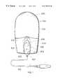
- FIG. 1is a top plan view of a computer desktop mouse with a plurality of exposed finger depressible buttons on a top of the housing and forward of a hand palm rest area.
- FIG. 2is a drawing of the FIG. 1 desktop mouse with a top half or portion of the housing removed or not yet assembled to show a rotatable pointer control ball, a circuit board and sensors and switches.
- FIG. 3is a drawing of the inside or underside of the housing top of the mouse of FIG. 1 .
- FIG. 4is a top plan view of another embodiment of computer desktop mouse with a plurality of exposed finger depressible buttons on a top of the housing top portion and positioned forward of a hand palm rest area.
- FIG. 5is a drawing of the FIG. 4 mouse with the top of the housing removed or not yet assembled to show a rotatable pointer control ball, a circuit board and sensors and switches.
- FIG. 6is a drawing of the inside or underside of the housing top of the mouse of FIG. 4 .
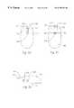
- FIG. 7shows a median cross section view of an elastomeric injection molded one-piece dome-cap sensor as could be used in a desktop mouse in accordance with the invention.
- the sensoris shown with the active element attached to the underside or bottom of the raised dome-cap and thus the active element is carried by and within the dome-cap.
- FIG. 8shows, for demonstration purposes, a simple electrical circuit arranged to be an analog sensing circuit and utilizing the elastomeric dome-cap sensor of FIG. 7 as a pressure-sensitive variable-conductance sensor.
- FIG. 9shows a median cross section view of another embodiment of elastomeric injection molded one-piece dome-cap sensor as could be used in a desktop mouse in accordance with the invention.
- the shown sensoris a structural arrangement wherein the active element is shown atop and spanning across two proximal conductive elements and within the confines of the injection molded dome-cap but not carried by the dome-cap.
- the elastomeric injection molded dome-capis shown in a raised position above the active element.
- FIG. 10shows, for demonstration purposes, a simple electrical circuit arranged to be an analog sensing circuit and utilizing the elastomeric dome-cap sensor of FIG. 9 as a variable-conductance sensor.
- FIG. 11shows a median cross section view of an elastomeric dome-cap sensor with the dome-cap depressed and representing the dome-cap sensors of either FIG. 7 or FIG. 9 in a state wherein compression or force of some level or amount is applied to the active element.
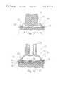
- FIG. 12shows a median cross section view of a sensor which uses an elastomeric injection molded one-piece dome-cap as could be used in a desktop mouse in accordance with the invention.
- the active elementis shown sandwiched between two membrane sheets which are separated by a center membrane sheet having a hole containing the active element.
- the active elementis shown beneath the underside center of the raised one-piece injection molded elastomeric dome-cap and below or outside of the dome-cap. In this illustration, the active element is shown neither carried by the dome-cap nor within the confines of the dome-cap.
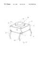
- FIG. 13shows a flat mount sensor or switch package which is structured in a novel manner inside the sensor and as could be used in a desktop mouse in accordance with the invention.
- FIG. 14shows a median cross section view of the FIG. 13 flat mount sensor package structured to be a pressure-sensitive variable-conductance sensor and useful with the present invention.
- FIG. 15shows a median cross section view of the sensor embodiment of FIGS. 13-14 in a depressed or actuated condition.
- FIGS. 16-18each show a top view of varied proximal conductive elements useful generally for interfacing between the active element of an elastomeric dome-cap sensor and a circuit board or circuit bearing membrane sheet or the like circuit bearing material.
- FIG. 19shows an overview of some of the primary components of a desktop mouse in accordance with the invention.
- FIG. 20shows a flow chart for achieving a dual role or dual output with a pressure-sensitive variable-conductance depressible button sensor.
- FIG. 21shows a cross section view of depressible rocker button with a central depressible switch in a desktop computer mouse housing.
- FIGS. 22-25show cross section views of depressible rocker buttons with sensors in a desktop computer mouse housing.
- FIGS. 26-31show top views of desktop computer mice having additional back and forward depressible buttons.
- FIG. 32shows a side view of a desktop computer mouse having additional back and forward depressible buttons.
- FIG. 1is a top plan view of a desktop operated computer control device, i.e., desktop mouse 100 with a plurality of finger depressible surfaces or buttons 103 on a single depressible plate 212 exposed on a top of the housing 104 top portion, and including a rotatable pointer control ball 110 (FIG. 2 ).
- Desktop mouse 100physically appears as some prior art desktop mice, yet is in accordance with the present invention, although the improved desktop mouse as taught herein can be shaped into different appearances including different button 103 layouts.
- Desktop mouse 100is conventionally structured much like some prior art desktop mice of the type having rotatable pointer control balls, right and left select buttons, and scroll-up and scroll-down finger depressible buttons.
- Another possible difference in mouse 100 from such prior art desktop miceis that the active element of the dome-cap sensors associated with scroll buttons 107 and 108 in the present invention may be formed of an improved pressure-sensitive variable-conductance material, i.e., having improved variable-conductance characteristics compared to the standard dome-cap active element which does have usable pressure-sensitive variable-conductance characteristics.
- housing 104contains or houses electronic circuitry such as on a circuit board 111 (FIG. 2) for interfacing with electrical sensors associated with the depressible buttons 103 , for detecting ball 110 movement and for communicating information related to activation thereof to a computer.
- some of the buttons 103are associated with momentary-On only On/Off switches which the circuitry reads only as such, i.e., On or Off, having only two readable states, while others of the buttons 103 are, in accordance with the invention, associated with pressure-sensitive variable-conductance sensors (analog sensors) which the circuitry reads as having at least three readable states, e.g., Off, first On state and second On state.
- Desktop mouse 100is also shown with a multi-conductor cable 102 connected thereto, cable 102 having a cord end as is common with desktop mice which plug into a port on a computer. Cable 102 would not be present on a desktop mouse in accordance with the invention which communicated with a computer through wireless communication such as infrared light for example only, and which contained a battery to provide electrical power to the circuitry of circuit board 111 . Cable 102 is shown in FIG.
- FIG. 1Also shown in FIG. 1 is a button 105 which is a left side select button which is probably best served by a normally-open momentary-On switch 118 (see FIG. 2) read as only having two readable states, and button 106 being right side select button which is probably best served by a normally-open momentary-On switch 119 (see FIG.
- buttons 107 and 108which in this example is a scroll-up button associated with an elastomeric dome-cap sensor 10 , 28 or 30 (see FIG. 2) structured as and used as an analog sensor as will be detailed later in this disclosure.
- button 108which in this example is a scroll-down button associated with an elastomeric dome-cap sensor 10 , 28 or 30 (see FIG. 2) structured as and used as an analog sensor as will be detailed later in this disclosure.
- the scroll up and scroll down button assignmentsmay be reversed if so desired by the user within the mouse driver software settings.
- the elastomeric dome-cap sensors associated with finger depressible buttons 107 and 108are shown in FIG. 2 as connected by a sheet, i.e., the dome-caps are integrally molded to a connecting sheet.
- a palm rest area 109is also shown in FIG. 1 on the top outer surface of housing 104 and rearward of buttons 107 and 108 .
- FIG. 2is a drawing of the FIG. 1 desktop mouse 100 with the top of the housing 104 removed to show the pointer control rotatable ball 110 arranged in a conventional mouse ball arrangement to be read by a first encoder 112 and a second encoder 113 or the like for reading movement of the ball 110 relative to housing 104 along X and Y axes and used for cursor control and pointing.
- Rotatable ball 110 , the mounting and movement reading arrangementtherefore may or can be of a conventional type in a desktop mouse in accordance with the invention.
- circuit board 111which includes electronic circuitry thereon, typically most of the electronic circuitry will be primarily in a microcontroller 114 or ASIC chip 114 (application specific integrated circuit) or a COB package (chip on board) or the like.
- FIG. 3is a drawing of the inside or underside of housing 104 top of desktop mouse 100 of FIG. 1 and showing moveable surfaces 120 , 121 , 122 , 123 which in this example are surfaces which are connected to or the actual bottom sides of the exposed button surfaces 103 depressible by fingers and which move with button depression to impinge directly on the depressible button of associated electrical switch or sensor associated with the exposed finger depressible button.
- surface 120moves down with depression of button 106 to impinge upon and depress the button of right select switch 119 and thus activate the switch; surface 121 moves down with depression of button 105 to impinge upon and depress the button of left select switch 118 and thus activate that switch; surface 122 moves down with depression of button 108 to impinge upon and depress the depressible portion or button (dome-cap) of scroll-down dome-cap sensor 10 , 28 or 30 depending on which sensor is used and thus to activate the analog sensor; and surface 123 moves down with depression of button 107 to impinge upon and depress the depressible portion or button (dome-cap) of scroll-up dome-cap sensor 10 , 28 or 30 .
- Varying amounts of pressurecan be applied to any of the switches and sensors by the user simply applying varying amounts of pressure to the associated button 103 or button area with his or her finger.
- the depressible button 103 of the individually identified buttons 107 and 108 of FIG. 1 and 3 of mouse 100is a rocker style depressible button arrangement having a center pivot (pivot not shown but approximately beneath the broken line in FIG. 1) in this example, allowing only one of the associated sensors to be depressed at any given time, and thus the rocker button can be viewed as two separate buttons 103 , however buttons 107 and 108 could be completely separate in terms of button surfaces 103 as indicated by a broken line in FIG. 1, and the dome-cap sensors associated therewith need not be connected in sheet form as shown in FIG. 2 .
- buttons 107 and 108 in mouse 100could be replaced with a package sensor 39 , an analog sensor which will be detailed later in this disclosure.
- the top exterior of an elastomeric dome-capcan provide an exposed finger engagement surface or button 103 on which a user can press absent a requirement of additional button caps or mechanical rockers atop the dome-cap, and typically the top of the dome-cap in this use would protrude through a hole in the housing to allow the user to place a finger directly thereagainst.
- buttons 107 and 108 forming a rockercan be structured without a center pivot and thus depression of the entire rocker stimulates opposing sensors 107 and 108 thus indicating a different functionality such as for example depression of a third or central selection button.
- FIG. 4is a top plan view of a desktop mouse 200 having a plurality of finger depressible buttons 103 exposed on the top of the case or housing 104 , and including a rotatable pointer control ball 110 (FIG. 5 ).
- Desktop mouse 200physically appears as some prior art mice yet is in accordance with the present invention, although the improved desktop mouse as taught herein can be shaped to appear substantially different and can include different depressible button layouts.
- Like parts serving like functions in mouse 100 and mouse 200have like numbers applied thereto.
- Desktop mouse 200with the exception of the electronic circuity particulary for reading scroll buttons 107 , 108 , 202 and 204 is conventionally structured much like some prior art desktop mice of the type having rotatable pointer control balls, right and left select buttons, scroll-up and scroll-down finger depressible buttons, and further including scroll-right and scroll-left depressible buttons.
- Another difference in mouse 200 from such prior art desktop miceis that while such prior art desktop mice include package switches or sensors appearing as those shown in FIG. 5, prior art package sensors do not include pressure-sensitive variable-conductance material for providing at least three readable states.
- Mouse 200is shown in FIG. 5 having four novel package sensors 39 , as will be detailed, package sensors 39 each include pressure-sensitive variable-conductance material for providing at least three readable states.
- mouse 200contains electronic circuitry inside housing 104 such as on a circuit board 111 (FIG. 5) for interfacing with electrical sensors associated with the depressible buttons 103 .
- buttons 103are associated with momentary-On only On/Off switches which the circuitry reads only as such, i.e., On or Off, or as having only two readable states
- others of the buttons 103such as scroll control buttons 107 , 108 , 202 and 204 are associated with pressure-sensitive variable-conductance sensors (analog sensors) such as in FIGS. 7, 9 , 11 , 12 or 13 - 15 (to be described below) which the electronic circuitry reads as having at least three readable states, e.g., Off, a first On state and a second On state which can be On low and On high for example.
- Mouse 200differs from mouse 100 in that mouse 200 further includes an optional scroll-right button 202 and a scroll-left button 204 , although the scroll-right and scroll-left buttons could be added to mouse 100 .
- Mouse 200includes a four-way rocker plate 208 in effect providing four depressible button surfaces 103 or areas for depressing with a finger, but allowing independent sensor actuation or for two adjacent sensors to be simultaneously actuated, such as for example only, scrolling up and to the right at the same time.
- the four associated sensorscould each be associated with only one completely separate button surface 103 if desired.
- FIG. 5is a drawing of the FIG. 4 mouse 200 with the top of the housing 104 removed to show pointer control rotatable ball 110 arranged in a conventional desktop mouse ball arrangement to be read by a first encoder 112 and a second encoder 113 or the like for reading movement of the ball 110 relative to housing 104 along X and Y axes and used for cursor or pointer control.
- Rotatable ball 110 , the mounting and movement reading arrangementtherefore may or can be of a conventional type in a desktop mouse in accordance with the invention.
- a circuit board 111having electronic circuitry thereon, and switches or sensors 118 and 119 .
- sensor 118is a momentary-On switch read by the circuitry of circuit board 111 as having only two readable states, i.e., On and Off, the switch being the left select switch associated with button 105 and impingement point 121 of FIG. 6 .
- Sensor 119is a momentary-On switch read by the circuitry as having only two readable states, i.e., On and Off, the switch being the right select switch associated with button 106 and impingement point 120 of FIG. 6 .
- Also shown in FIG. 5are four packaged sensors 39 each in accordance with a novel structure of packaged analog sensor 39 to be detailed below.
- One sensor 39is the sensor associated with the 107 button for initiating scroll-up, another sensor 39 is the sensor associated with the 108 scroll-down button, another sensor 39 is associated with button 202 to be initiated thereby, and the fourth sensor 39 is associated with button 204 to be initiated thereby when the human user depresses the button.
- the sensors 39are electrically connected to the circuitry or electronic circuits of circuit board 111 .
- FIG. 6is a drawing of the inside or underside of the housing top of the mouse of FIG. 4 . Shown are moveable surfaces 120 , 121 , 122 , 123 , and additionally moveable or impingement surfaces 209 and 210 which in this example are surfaces which are connected to the undersides of exposed button surfaces 103 depressible by fingers and which move with button depression to impinge directly on the sensor activating button of the associated electrical switch or sensor associated with the button 103 . Specifically, surface 120 impinges on switch 119 ; surface 121 impinges on switch 118 ; 122 impinges upon and depresses button-like actuator 44 (FIG.
- the four impingement surfaces 122 , 123 , 209 and 210 in FIG. 6are all, in the shown example, on a single four-way rocker plate 208 having an optional center pivot point 211 which allows the impingement points to contact one at a time, or possibly two adjacent sensors 39 at a time.
- Rocker plates for activating sensorsare well understood by those skilled in the art. It should be noted sensors 39 in mouse 200 could be replaced with dome-cap analog sensors such as sensor 10 , 28 or 30 to be described below.
- Plate 208is a lower portion of the shown plate 208 of FIG. 4 and is movably retained to housing 104 .
- Four completely individual depressible buttons 103could be used instead of the depressible rocker plate 208 arrangement, however because rocker plate allows, by its rocker action, single electrical sensor actuation, the four finger depressible areas can be considered four finger depressible buttons 103 .
- Plate 208can be structured without a center pivot 211 and thus depression of the entire button 208 stimulates opposing sensors 202 and 204 , or 107 and 108 thus indicating a different functionality such as for example depression of a third or central selection button.
- FIG. 7shows a median cross section view of an elastomeric dome-cap sensor 10 as can be used in a desktop mouse in accordance with the invention.
- Elastomeric dome-cap sensor 10is an electrical sensor using an elastomeric injection molded one-piece dome-cap 12 as a component thereof.
- Dome-cap sensor 10is in accordance with the prior art and can be used in a novel new use of such a sensor in a desktop mouse as a pressure sensitive analog scroll control, and in a novel new structural combination as herein disclosed in accordance with the present invention.
- Dome-cap sensor 10may include an improved pressure-sensitive variable-conductance material active element 14 such as by utilizing material 54 to be described below.
- Sensor 10is shown in the deactivated state or condition with the elastomeric one-piece injection molded dome-cap 12 raised and thus the active element 14 , i.e., conductive pill is shown raised and disengaged from two proximal conductive elements 16 , 18 .
- the sensor 10is in a “state” which is readable by circuitry and which could or can be considered an Off state or first state of at least three readable states.
- the two proximal conductive elements 16 and 18are or would be conductive elements of the circuitry on circuit board 111 or the like circuit bearing member.
- the active element 14is attached to the underside of dome-cap 12 and is thus carried by the dome-cap, the attaching most commonly being by the dome-cap 12 being formed by injection molding to the pre-formed active element 14 which has been inserted into the molding cavity prior to the injecting of the thermoset rubber commonly used to make highly durable dome-caps 12 .
- Multiple shot injection or adhesive attachment or any other suitable connectioncan be used to connect active element 14 to injection molded dome-cap 12 .
- Conductive elements 16 , 18are shown attached to or supported by a typically non-conductive base 20 which is a board of a circuit board such as circuit board 111 , a flexible membrane sheet, combination thereof or the like.
- Dome-cap 12is shown with an outward extending flange 22 at it's bottom end on base 20 extending parallel to base 20 .
- Flange 22is typically integrally injection molded or in one-piece with the balance of dome-cap 12 .
- Flange 22can be adhered in place to base 20 such as with adhesives or dome-cap 12 can be otherwise held in proper location to base 20 and conductive elements 16 , 18 such as with mechanical restraints, as for example by sandwiching flange 22 between portions of a housing or the like, or by having the upper portion of dome-cap 12 positioned within a movement restricting opening in a housing which only allows the upper portion to move toward and away from base 20 and conductive elements 16 , 18 .
- Flange 22can be a portion of the sheet 16 connecting multiple dome-caps 12 .
- the FIG. 7 sensor, but with the active element containing tungsten carbide (such as material 54 to be detailed)is a highly preferred sensor embodiment for use with or in conjunction with the present invention.
- FIG. 8shows a simple electrical circuit structured to be an analog sensing circuit and utilizing the elastomeric dome-cap sensor 10 of FIG. 7 as a pressure-sensitive variable-conductance sensor.
- “Analog sensing circuit”is one which is structured to be at least in part manipulated or controlled by operation of an analog sensor, the analog sensor being a sensor capable of being read by electronic circuitry including analog sensing circuitry as having at least three readable states dependant upon applied depressive pressure. No applied depressive pressure can be and will normally be treated as an amount of depressive pressure and associated with one of the three readable states.
- a battery 24as an example of an electrical power source in the circuit, cord 102 would bring in electrical powered in a cord connected desktop mouse.
- a meter 26including an electromagnetic coil engaged to a moveable indicating needle adjacent a printed scale or range gauge and capable of showing varying conductivity across the elastomeric dome-cap sensor 10 .
- the dome-cap sensor 10is indicated in the circuit as being in what could be considered a first or open state in this example. It should be understood that depressive pressure applied to the dome-cap 12 will move the raised portion of the dome-cap 12 toward base 20 sufficiently to bring the active element 14 into contact with both conductive elements 16 , 18 , and with sufficient pressure, and varying pressure well within a range readily applied by a human finger, the sensor 10 will be moved to second and third, etc.
- the scale of meter 26 in this exampleincludes marks which the needle moves through, in this example the needle moving to the right as the resistivity of the active element 14 decreases. It can be appreciated that while the marks are only printed on the scale, each mark represents a position the needle can pass through, and an electrical state of the sensor in which each can have a digital bit assignment associated therewith. In this example, higher pressure to dome-cap 12 and active element 14 would move the needle further to the right indicating lower resistivity, i.e. greater conductivity of active element 14 .
- digital bit assignmentscan be made for any level or state of conductivity and at least two bits of digital information are required for identifying more than two readable states.
- Such digital informationcan readily be used as control signals such as scroll control signal communicated from the desktop mouse to a computer.
- meter 26is only for illustrative purposes, as such a meter with needle is not anticipated as being required in a mouse in accordance with the invention.
- FIG. 9shows a median cross section view of an elastomeric dome-cap sensor 28 structured with the active element 14 , mounted or freely resting atop and spanning across the two proximal conductive elements 16 , 18 .
- the dome-cap 12is shown in a raised position above the active element 14 (or 54 ) and the sensor is shown in what can be used as or considered as a deactivated state or first state (off or open state) since no compressive pressure or force is being applied to active element 14 .
- the conductive pill or active element 14 of a typical prior art dome-cap sensoris a moderate to poor conductor when not compressed and becomes a much improved conductor under compression, and this means that if active element 14 of the FIG.
- FIG. 10shows a simple electrical circuit arranged to be an analog sensing circuit and utilizing the elastomeric dome-cap sensor 28 of FIG. 9 as a pressure-sensitive variable-conductance sensor in combination with a meter 26 .
- the needle of meter 26is shown moved somewhat to the right to indicate compressive force being applied to active element 14 with dome-cap 12 depressed as shown in FIG. 11 wherein the sensor is in an activated state.
- meter 26is only for illustrative purposes, as such a meter with needle is not anticipated as being required in a mouse in accordance with the invention.
- FIG. 11shows a median cross section view of an elastomeric dome-cap sensor with the sensor shown in the activated state or condition with the dome-cap 12 depressed and representing the dome-cap sensors of either FIG. 7 or FIG. 9 in the activated state, i.e., activated state meaning with the active element 14 under a degree of compression from the depressed dome-cap 12 .
- Deactivated stategenerally meaning the active element 14 is not being compressed by the dome-cap 12 .
- FIG. 12shows a median cross section view of an elastomeric dome-cap sensor 30 in the deactivated state or condition with active element 14 sandwiched between two non-conductive flexible membrane sheets 32 , 34 which are separated by a center membrane sheet 36 which includes a hole therein filled with active element 14 .
- the membrane sheetsare shown atop a stiff base 20 beneath the underside center of the raised dome-cap 12 which is mounted atop the upper most membrane sheet.
- Two proximal conductive elements 16 , 18are shown between the membrane sheets 32 , 34 and contacting opposite sides of active element 14 .
- the proximal conductive elements 16 , 18can be printed conductive ink on membranes 32 and 34 .
- Active element 14which is not carried by dome-cap 12 is shown beneath the underside center of the raised dome-cap 12 and outside of, or not within dome-cap 12 , but rather is below the bottom surface of flange 22 .
- the dome-cap 12can be manually depressed to move toward base 20 to apply pressure on the nearest membrane sheet 32 which will flex and transfer depressive force into active element 14 which will alter it's conductivity relative to the degree of compression or force thereon, thus altering the conductivity through active element 14 between proximal conductive elements 16 , 18 .
- FIG. 12additionally shows that dome-cap 12 can be manufactured with uniform wall thickness such as to accommodate certain materials which mold and perform in an improved manner when kept uniform in thickness, as opposed to those embodiments shown in FIGS. 7, 9 and 11 which have an upper portion of much greater thickness than the lower portion of the dome-cap 12 .
- FIG. 12shows active element 14 sandwiched between conductive elements 16 and 18 as taught in the R. J. Mitchell U.S. Pat. No. 3,806,471 issued Apr. 23, 1974, and further sandwiched between membrane sheets as shown in the F. Eventoff U.S. Pat. No. 4,315,238 issued Feb. 9, 1982 as a bounceless On/Off switch.
- My addition of the elastomeric injection molded one-piece dome-cap 12 in this embodimentcreates a novel sensor with some, but not all, of the above discussed advantages afforded to an injection-molded dome-cap sensor having analog or pressure sensitive properties. While the novel embodiment of FIG. 12 is or would be functional with the present invention, it is not the most preferred sensor discussed herein for certain reasons such as: this embodiment is not the lowest cost manufacturing technology discussed herein, or the easiest to manufacture, or the best performing sensor embodiment described herein.
- the present inventionprovides for ease of changeover by manufactures who currently make desktop mice for computer control which include housings with circuit boards therein, elastomeric dome-cap sensors associated with the circuit boards and used for scrolling control, the housings structured to allow access or the like to the dome-caps to allow depression thereof either directly with the finger or through additional button structures 103 , and rotatable balls in-part exposed for rotation relative to the housing for pointer control.
- the at least three states of the dome-cap and active element (sensor)can represent at least: 1) no pressure, 2) low pressure, and 3) high pressure applied to the dome-cap and thus the active element and different level of conductivity thereof.
- the three statesare defined, for example, by the different levels of conductance of the active element such as when under no pressure and essentially deactivated, and when under compressive pressure at a first level and when under compressive pressure at a second level.
- Each state or valuecan be associated with an individual bit or digital assignment, although if the no pressure or first pressure level of the analog sensor is treated as an open switch not requesting action, typically there would not be a need for a function-control signal to be sent from the desktop mouse 100 or 200 to a host computer for this first state, but second and third states would be associated with a bit or digital assignment which resulted in a control signal or scroll control signal being communicated from the mouse 100 or 200 to the host computer.
- Analog to digital conversionconnotes transferring the variable or different electrical states of the active element in a manner requiring a minimum necessary or required number of digital bits to describe a maximum possible number of variable states.
- the conversion requiring at least two digital bits or equivalent wording theretomeans that the active element 14 , being variably conductive, i.e., variably resistive or variably rectifying, can be described as having more than only two possible states of electrical conductivity, and those states can be described with digital information (bits).
- bitsbits necessary (required) to describe a specific possible number of states is well known by those skilled in the art, as the possible described states is a factor of the bits required to describe such states.
- two different statesrequire at least one digital bit to describe, On or OFF, the bit is a zero or a one; three different states require at least two digital bits to describe; and three bits are required to describe a minimum of 5 states; to describe a somewhat smoothly variable active element having 256 states requires at least eight bits of digital information, etc.
- the term “storing”means that a representative value of a read state of the active element 14 is at least stored in some register at some time within the digital electronics processing the status of the active element 14 .
- variable conductancecan be achieved with other materials having either variable resistive properties or variable rectifying properties.
- variable-conductance and equivalents theretomeans either variably resistive or variably rectifying.
- Pressure-sensitive variable-conductance material 54 as herein used particularly in reference to FIGS. 13-15 (to be described below)is such material.
- Active element 14is also pressure-sensitive variable-conductance material. Material having these qualities can be achieved utilizing various chemical compounds or formulas some of which I will herein detail for example. Additional information regarding such materials can be found in the R. J. Mitchell patent describing various feasible pressure-sensitive variable-conductance material formulas which can be utilized.
- variable resistive type materials for defining active element 14 or material 54are optimum for use in pressure sensor(s), variable rectifying materials are also usable within the scope of the present invention.
- An example formula or compound having variable rectifying propertiescan be made of any one of the active materials copper oxide, magnesium silicide, magnesium stannide, cuprous sulfide, (or the like) bound together with a rubbery or elastomeric type binder having resilient qualities such as silicone adhesive or the like.
- An example formula or compound having variable resistive propertiescan be made of the active material tungsten carbide powder (or other suitable material such as molybdenum disulfide, sponge iron, tin oxide, boron, and carbon powders, etc.) bound together with a rubbery or elastomeric type binder such as silicone rubber or the like having resilient qualities.
- the active material tungsten carbide powdermay be in proportion to the binder material in a rich ratio such as 90% active material to 10% binder by weight, but can be varied widely from this ratio dependant on factors such as voltages to be applied, level or resistance range desired, depressive pressure anticipated, material thickness of the active element, surface contact area between the variable-conductance material and conductive elements of the circuit, binder type, manufacturing technique and specific active material used.
- tungsten carbide powder bound with a rubbery or elastomeric type bindersuch as silicone rubber or the like provides a wider range of varying resistance than the typical carbon pill or active element 14 of the prior art dome-cap switches and thus may be preferred particularly for applications requiring high resolution or low power consumption.
- the tungsten carbide based active elementis more predictable in it's pressure sensitive varying conductivity over a wider temperature range than the typical carbon based active element used in prior art dome-cap switches.
- FIG. 13shows a flat mount sensor package 39 which outwardly appears as many prior art switches or sensors.
- Sensor 39is a novel analog sensor capable of variable conductance through at least three readable states, and such a sensor is not known to exist in the prior art.
- the analog sensor 39 of FIGS. 13-15can be used in a desktop mouse in accordance with the present invention.
- FIG. 13shows four extensions external of housing 38 which those skilled in the art understand in regards to prior art switch packages are in effect two conductive elements 40 , 42 wherein two of the extensions represent portions of first conductive element 40 external to housing 38 , and the other two extensions represent portions of second conductive element 42 ; as is common in many prior art switch packages for allowing increased strength and options in mechanical and electrical connecting, and such multi-extensions external of housing 38 for each conductive element 40 , 42 can also be used on sensors 39 used with the present invention.
- Housing 38is typically of non-conductive plastics, and the two conductive elements 40 and 42 are typically highly conductive and of fairly constant conductivity; the conductive elements 40 , 42 each fixed to housing 38 and in-part within housing 38 and in-part exposed external of housing 38 .
- Conductive elements 40 , 42are herein sometimes referred to as first conductive element 40 and second conductive element 42 , and are typically formed via stamping and bending of sheet metal.
- housing 38is of non-conductive plastics molded around portions of conductive elements 40 and 42 so as to retain the conductive elements in proper location to housing 38 .
- a housing closing plate 46 and retaining studs 48at the corners for retaining plate 46 on the balance of housing 38 , and depressible button or button-like actuator 44 extending from within housing 38 through an opening in plate 46 .
- FIG. 14shows a median cross section view of the package sensor 39 of FIG. 13 and showing pressure-sensitive variable-conductance material 54 within a recess or well 50 inside housing 38 contacting second conductive element 42 and capped by an optional conductive cap 52 .
- the FIG. 14 sensor 39includes the optional conductive cap 52 , which can be used to define a lamination of pressure-sensitive variable-conductance material 54 onto conductive sheet material and then cut-out with a hole punch prior to insertion in to the well 50 of the housing of the sensor package.
- Conductive cap 52 being atop pressure-sensitive variable-conductance material 54is effectively closing pressure-sensitive variable-conductance material 54 within well 50 .
- Conductive cap 52should either be flexible so as to be able to bow into pressure-sensitive variable-conductance material 54 , or loose fit in well 50 so as to be able to move in it's entirety into pressure-sensitive variable-conductance material 54 when pressure is applied thereto by snap-through dome-cap 16 to be detailed.
- Conductive elements 40 , 42are shown separated from one another within housing 38 and in a normally open state or circuit, being separated by space and the insulating material defining housing 38 .
- An end portion of first conductive element 40 within housing 38is shown positioned in constant contact with a side edge of dome-cap 56 .
- Dome-cap 56is a circular resilient disk having a domed or concavo-convexed shape and typically made of electrically conductive metal.
- Dome-cap 56is shown positioned within a large recess or the interior open space defined by housing 38 and between depressible button or actuator 44 and conductive elements 40 , 42 . As shown in FIG. 15, in this sensor 39 embodiment, depression of actuator 44 sufficiently causes dome-cap 56 to bow downward causing a center portion of dome-cap 56 to contact conductive cap 52 . If cap 52 is not used, dome-cap 56 would contact material 54 directly. Well 50 is also optional.
- dome-cap 56when pressed against by way of depressive pressure applied to actuator 44 bows toward conductive cap 52 with a degree of resistance to moving, the resistance begins relatively low and increases toward a snap-through threshold wherein at the snap-through threshold dome-cap 56 “snaps-through” and moves further downward.
- a snap or clickcan be felt and in some applications heard (user discernable tactile feedback) as dome-cap 56 snaps-through its threshold.
- the snap-through dome-cap 56being of resilient design, returns to a raised position off of conductive cap 52 when actuator 44 is no longer depressed, and thus sensor 39 is a momentary-On analog type sensor capable of outputs of many different readable states. Also, the resiliency of the metal dome-cap 56 is used as the return spring for depressible actuator 44 , holding the actuator 44 raised or outward when not depressed by an external force such as a human finger.
- Depressible actuator 44is shown protruding through opening 58 in plate 46 , and is prevented from passing completely through opening 58 by a flange 60 connected to actuator 44 and too large to pass through opening 58 .
- the portion of depressible actuator 44 which is external of housing 38can be of numerous sizes, shapes and lengths, for example to accommodate the attachment of or contacting of extending and/or enclosing members such as buttons, or to serve directly as a surface against which a finger can be applied to depress the actuator 44 .
- FIG. 15shows a median cross section view of the packaged sensor 39 embodiment of FIGS. 13-14 with actuator 44 depressed, such as it would be by a user's finger or thumb, to such a degree as to cause dome-cap 56 to impinge upon conductive cap 52 atop the pressure-sensitive variable-conductance material 54 .
- the pressure applied to conductive cap 52is transferred in pressure-sensitive variable-conductance material 54 and the conductance between circuit elements 40 and 42 is varied upon varied compressive pressure on material 54 .
- Numerous variations of the analog sensor 39 of FIGS. 13-15 structurecan be made, and such analog sensors can be used in a desktop mouse in accordance with the invention.
- Circuit elements 40 and 42solder or otherwise electrically connected to circuitry of the desktop mouse, such as the circuitry of circuit board 111 allowing the packaged analog sensor 39 to interface with the circuitry and electronics of the mouse 100 or 200 .
- Button-like actuator 44while shown small in the portion thereof exposed external of the housing 38 so as to be placed underneath an exposed finger depressible button, can be made larger and re-shaped if desired, and exposed through a hole in the mouse housing for directly interfacing with a human finger.
- FIGS. 16-18show a top view of two conductive elements 16 , 18 in various proximal arrangements as they may be applied to a circuit board 111 in sensor embodiments useful with the present invention, particularly elastomeric dome-cap sensors wherein the active element 14 (or material 54 ) spans the two proximal conductive circuit elements 16 , 18 to bridge the elements which are extensions of the circuitry of a circuit board such as discussed above in regards to circuit board 111 .
- the elastomeric dome-cap sensorelectrically interfaces with the associated circuitry of the circuits of circuit board 111 .
- FIG. 16shows two conductive elements 16 , 18 as two side-by-side plate-like pads.
- FIG. 17shows two conductive elements 16 , 18 as two side-by-side pads having opposed fingers.
- FIG. 18shows two conductive elements 16 , 18 as two side-by-side pads defined by interdigitated fingers.
- FIG. 19shows an overview of some of the primary components of desktop mouse 100 having a rotatable ball 110 read by encoders 112 , 113 for pointer control, select buttons 118 , 119 , and inputs to microcontroller 114 .
- the arrangementis the same for mouse 200 except mouse 200 would include two additional scroll control analog depressible buttons for the scroll right and left functions.
- device 100also has pressure-sensitive variable-conductance material 54 as an active element of sensor types such as finger depressible analog scroll buttons or sensors 39 , 10 , 28 , 30 for inputting data representing the analog value or current state to microcontroller 114 .
- Microcontroller 114outputs, such as through a serial port PS/2 or USB or the like, for output of screen scrolling control signals for at least two scroll rates or speeds, select button function-control signals and pointer control signals to a host computer with monitor.
- FIG. 20shows a pressure-sensitive variable-conductance depressible button sensor such as the dome-cap sensors of FIGS. 7 or 9 , or the package sensor of FIGS. 13-15 and indicated as a variable resistor connected in a battery powered circuit including a counter with analog-to-digital conversion circuitry for storing and outputting digital information such as could be used with a dual role pressure-sensitive variable-conductance depressible button sensor in computer control mouse in accordance with the present invention.
- FIG. 20being primarily regarding the “dual role” of the analog sensors in a mouse for computer control as mentioned above.
- a first signal typesuch as an only On/Off signal type
- a second signal typesuch as a variable signal representative of differing levels of depressive pressure applied
- the flow chartdemonstrates that the program first looks at variable resistor of the sensor 39 , 10 , 28 , 30 or the like depending on which sensor is used, and reads 80 the sensor's current state. The program flow control then goes to decision 82 based on the question “is the sensor activated?” If the sensor is activated, a counter is incremented 84 indicating that the sensor has been read as activated. Additionally the sensor state or value is stored in a storage register(s) and averaged 86 (or equivalent) with any other previous read values. The counter value is read, and a decision 88 is made depending on the counter value, if the counter value is not sufficiently high, for example, ten reads of the sensor, then the sensor is read 80 again.
- the buttonhas been held sufficiently long, for example, 1 ⁇ 4 of a second or longer, and the second type signal is output 90 to the computer (or if the above processing is performed within the computer then the output would be to video output portions of the computer or monitor) representing the level of depressive pressure applied to the button and analog sensor 39 , 10 , 28 , 30 .
- the counter and storage register(s)are then cleared or reset 92 .
- the counter valueis examined 96 , if the counter value is not of a sufficient value, for example, at least more than one, then any previously stored sensor activation is considered spurious and discarded, the counter and storage values are reset 92 and the sensor is read 80 again.
- the counter valueis greater than one for example, then the button is deemed to have been pressed and immediately released so the first type signal is output 98 to the computer/video circuitry/monitor, the counter and storage register(s) are then reset, and the sensor is read 80 again.
- the dual role sensor outputoffers advantage in for example, moving back to a previous address or screen wherein initiation thereof is achieved by a quick press and release of the sensor button, and screens or windows may be scrolled at a desired speed by continuous user selected depressive pressure on a button of the mouse.
- FIG. 21shows a cross section view of depressible rocker button 212 , 208 with a central depressible switch 214 which in this example is a thick-walled elastomeric dome-cap switch or sensor including an active element 14 .
- a central depressible switch 214which in this example is a thick-walled elastomeric dome-cap switch or sensor including an active element 14 .
- Downward depending point 216 of rocker button 212 , 208rests upon sensor 214 in such a way that depression of button 212 , 208 centrally causes point 216 to collapse sensor 214 to effect the electrical state of the sensor. Depression of button areas 107 and 108 can be achieved independently in a rocker manner and without actuating sensor 214 .
- FIGS. 22-25show cross section views of depressible rocker buttons 212 , 208 with sensors, such as 10 , 28 , 30 , 39 in a desktop computer mouse housing 104 .
- Rocker button 212 , 208can, because of a lack of a central pivot, be rocked at button area 107 (FIG. 23) or button area 108 (FIG. 24) to actuate only one of the opposing sensors 10 , 28 , 30 , 39 , at a time, or alternatively, the button can be centrally depressed to actuate more than one of the opposing sensors simultaneously (FIG. 25 ), such as for a achieving a third functionality.
- FIGS. 26-31show top views of desktop computer mice having additional back and forward depressible buttons
- FIG. 32shows a side view of a desktop computer mouse, each having additional back 220 and forward 222 depressible buttons, such as may be used to advantage in operating as common back and forward software buttons such as used in Internet browsers and the like for changing backwards or forwards to other graphical imagery as may be in a sequential nature.
- Back and forward buttons 220 and 222may operate in a limited manner as simple switches, and in a more advanced manner as analog depressible buttons, for example, analog depressible back and forward buttons easily allow variable control of video frames rate so that video imagery may be reversed slow or fast, and played forward at varied speeds determinable by user applied-depressive pressure on the button.
- rocker buttons 212 , 208which may or may not be used in conjunction with back and forward buttons 220 , 222 .
- Back and forward buttons 220 , 222may be used with other desktop computer mice than described herein, such as for example computer mice with any type of cursor control technology and desktop mice having a roller type scrolling device, or no scrolling device.
- the invention from one view pointis an improved desktop operated computer control device (desktop mouse) of the type having a rotatable ball for pointer control, and further of the type including a housing, electronic circuitry within the housing and coupled to communication means, wired or wireless, for communicating control signals from the electronic circuitry to a computer.
- desktop operated computer control devicedesktop mouse
- the invention from one view pointis an improved desktop operated computer control device (desktop mouse) of the type having a rotatable ball for pointer control, and further of the type including a housing, electronic circuitry within the housing and coupled to communication means, wired or wireless, for communicating control signals from the electronic circuitry to a computer.
- the desktop control device or mousefurther including a plurality of finger depressible buttons exposed on the housing and interfacing with sensors electrically connected with the electronic circuitry for allowing user selection of control signals communicated to a computer; at least two of the sensors each capable of providing at least three readable states of varied conductance, at least two states of the at least three readable states, (e.g., Off, and at least two states or values of ON) dependant upon depressive pressure applied to the variable-conductance sensors through depression of an associated finger depressible button;
- a plurality of finger depressible buttonsexposed on the housing and interfacing with sensors electrically connected with the electronic circuitry for allowing user selection of control signals communicated to a computer; at least two of the sensors each capable of providing at least three readable states of varied conductance, at least two states of the at least three readable states, (e.g., Off, and at least two states or values of ON) dependant upon depressive pressure applied to the variable-conductance sensors through depression of an associated finger depressible button;
- the electronic circuitryincluding means for reading the at least three readable states and for producing a distinct control signal for each state of the at least two states.
- Such electronic circuitryincluding analog sensing circuitry and analog-to-digital conversion capabilities wherein distinct bit assignments are applied for each state of the at least two states, or a great number of states over a continuous spectrum of varied “On” states, the bit assignments defining distinct control signals such as for screen scrolling control signals, and used to determine different scrolling speed rates.
- the inventioncan be described as an improved desktop operated computer control device of the type having a rotatable ball for pointing control on a computer monitor, the control device further of the type including a housing, electrical power source means, i.e. power cord or battery for powering electronic circuitry, the electronic circuitry located within the housing, the electronic circuitry coupled to communication means, i.e., data cable or wireless transmitter, for communicating control signals from the electronic circuitry to a computer, a plurality of finger depressible buttons exposed on the housing and interfacing with sensors electrically connected with the electronic circuitry for allowing user selection of control signals communicated to a computer;
- electrical power source meansi.e. power cord or battery for powering electronic circuitry
- communication meansi.e., data cable or wireless transmitter
- At least two of the sensorseach structured to provide at least three readable states of varied conductance, the states dependant upon depressive pressure applied individually to the sensors of the at least two sensors;
- the electronic circuitryincluding means for reading the at least three readable states and for producing scroll control signals representative of each of at least two states of the at least three readable states;
- a first sensor of the at least two sensorsthe first sensor associated with a first button of the finger depressible buttons, the first button variably depressible to allow applying varied depressive pressure to the first sensor, the first sensor connected to the electronic circuitry, the electronic circuitry for reading the at least three readable states, (e.g., Off, and at least two states or values of ON) and producing at least two different scroll-up type signals as the scroll control signals;
- the at least three readable statese.g., Off, and at least two states or values of ON
- a second sensor of the at least two sensorsthe second sensor associated with a second button of the finger depressible buttons, the second button variably depressible to allow applying varied depressive pressure to the second sensor, the second sensor connected to electronic circuitry, the electronic circuitry for reading the at least three readable states, (e.g., Off, and at least two states or values of ON) and producing at least two different scroll-down type signals as the scroll control signals.
- the at least three readable statese.g., Off, and at least two states or values of ON
- the present inventioncan be described as an improved method of controlling window scrolling of a computer using a desktop operated computer control device (desktop mouse) of the type having a rotatable ball for pointer control, the control device further of the type including a housing, an electrical power source connecting to electronic circuitry within the housing, the electronic circuitry coupled to communication means such as conductor cords or wireless links for communicating control signals from the electronic circuitry to a computer, a plurality of finger depressible buttons exposed on the housing and interfacing with sensors electrically connected with the electronic circuitry for allowing user selection of control signals communicated to a computer; the control device further of the type wherein a user depresses a scroll control button of the buttons to activate a scroll control signal related to the depressed button, and releases the depressed button to deactivate the scroll control signal;
- a desktop operated computer control devicedesktop mouse
- the control devicefurther of the type including a housing, an electrical power source connecting to electronic circuitry within the housing, the electronic circuitry coupled to communication means such as conductor cords
- the scroll control buttondepressing, by the user, the scroll control button with any user selectable pressure level of a plurality of user selectable pressure levels, the user selectable pressure levels associated with various distinct scroll control signals defining different scroll rates (speeds), whereby the user controls screen scrolling rate by way of selecting the pressure applied to the scroll control button, preferably wherein increasing pressure applied to the scroll control button increases scrolling rate, and decreasing pressure applied to the scroll control button by the user is for decreasing scrolling rate.
- the present inventioncan be described as a method of manufacturing an improved desktop operated computer control device of the type having a rotatable ball for pointer control including the known prior art steps of: molding a housing; installing means for receiving a power source; installing electronic circuitry within the housing and connected to the power source; connecting communication means, conductive cords or wireless linking, to the electronic circuitry for communicating from the control device to a computer; installing a rotatable ball; connecting to the electronic circuitry means for sensing rotation of pointer control ball for pointer control; installing a plurality of finger depressible buttons positioned for bearing on sensors electrically connected with the electronic circuitry; the electronic circuitry optionally for reading a plurality of the sensors as sensors having only two readable values, such as the right and left select sensor buttons; and
- variable-conductance sensorsactivated by depression of finger depressible buttons, the variable-conductance sensors structured to provide at least three readable values, the values dependant upon depressive pressure applied to the pressure-sensitive variable-conductance sensors;
- circuitrysuch as analog sensing circuitry for reading an immediate value of the at least three readable values of the pressure-sensitive variable-conductance sensors, and for communicating from the control device (desktop mouse) to a computer data representative of the immediate value,
- improved desktop deviceis manufactured for communicating data representative of the depressive pressure applied to the pressure-sensitive variable-conductance sensors.
Landscapes
- Engineering & Computer Science (AREA)
- General Engineering & Computer Science (AREA)
- Theoretical Computer Science (AREA)
- Human Computer Interaction (AREA)
- Physics & Mathematics (AREA)
- General Physics & Mathematics (AREA)
- Position Input By Displaying (AREA)
Abstract
Description
Claims (28)
Priority Applications (1)
| Application Number | Priority Date | Filing Date | Title |
|---|---|---|---|
| US09/167,314US6198473B1 (en) | 1998-10-06 | 1998-10-06 | Computer mouse with enhance control button (s) |
Applications Claiming Priority (1)
| Application Number | Priority Date | Filing Date | Title |
|---|---|---|---|
| US09/167,314US6198473B1 (en) | 1998-10-06 | 1998-10-06 | Computer mouse with enhance control button (s) |
Publications (1)
| Publication Number | Publication Date |
|---|---|
| US6198473B1true US6198473B1 (en) | 2001-03-06 |
Family
ID=22606852
Family Applications (1)
| Application Number | Title | Priority Date | Filing Date |
|---|---|---|---|
| US09/167,314Expired - Fee RelatedUS6198473B1 (en) | 1998-10-06 | 1998-10-06 | Computer mouse with enhance control button (s) |
Country Status (1)
| Country | Link |
|---|---|
| US (1) | US6198473B1 (en) |
Cited By (154)
| Publication number | Priority date | Publication date | Assignee | Title |
|---|---|---|---|---|
| KR20010085104A (en)* | 2001-08-08 | 2001-09-07 | 김여일 | Multy purpose computer mouse system equipped with butten scrolling function etc. |
| US6310606B1 (en) | 1992-03-05 | 2001-10-30 | Brad A. Armstrong | Multi-plane sheet connected sensors |
| US6344791B1 (en) | 1998-07-24 | 2002-02-05 | Brad A. Armstrong | Variable sensor with tactile feedback |
| US20020019259A1 (en)* | 1997-10-01 | 2002-02-14 | Armstrong Brad A. | Controller with analog pressure sensor (s) |
| US6348912B1 (en)* | 1999-05-25 | 2002-02-19 | Micron Technology, Inc. | Family mouse |
| US6351257B1 (en)* | 1999-07-08 | 2002-02-26 | Primax Electronics Ltd. | Pointing device which uses an image picture to generate pointing signals |
| US20020024502A1 (en)* | 2000-08-31 | 2002-02-28 | Junichi Iwasaki | Mouse |
| US20020036660A1 (en)* | 1998-09-14 | 2002-03-28 | Adan Manolito E. | Input device with forward/backward control |
| US6373470B1 (en)* | 2000-01-12 | 2002-04-16 | Apple Computer, Inc. | Cursor control device having an integral top member |
| US6400303B2 (en) | 1998-09-04 | 2002-06-04 | Brad A. Armstrong | Remote controller with analog pressure sensor (S) |
| US6404584B2 (en) | 1997-10-01 | 2002-06-11 | Brad A. Armstrong | Analog controls housed with electronic displays for voice recorders |
| US20020084986A1 (en)* | 2001-01-04 | 2002-07-04 | Armstrong Brad A. | Computer mouse with specialized button(s) |
| US6415707B1 (en) | 1997-10-01 | 2002-07-09 | Brad A. Armstrong | Analog controls housed with electronic displays for coffee makers |
| US20020109672A1 (en)* | 2000-12-22 | 2002-08-15 | Logitech Europe S.A. | Pointing device with solid-state roller |
| US20020118168A1 (en)* | 2001-02-26 | 2002-08-29 | Hinckley Kenneth P. | Positional scrolling |
| US20020118169A1 (en)* | 2001-02-26 | 2002-08-29 | Hinckley Kenneth P. | Method and system for accelerated data navigation |
| US6456778B2 (en) | 1997-10-01 | 2002-09-24 | Brad A. Armstrong | Analog controls housed with electronic displays for video recorders and cameras |
| US6469691B1 (en) | 1999-05-11 | 2002-10-22 | Brad A. Armstrong | Analog controls housed with electronic displays for hand-held web browsers |
| US20020163507A1 (en)* | 2001-05-07 | 2002-11-07 | Chi-Lei Kao | Touch panel display aiding interface |
| WO2002101639A1 (en)* | 2001-06-13 | 2002-12-19 | Em Microelectronic-Marin Sa | Device for detecting movements of an object surface |
| US20020196231A1 (en)* | 1999-05-10 | 2002-12-26 | Joshua M. Dobies | Pointing device for navigating a 3 dimensional gui interface |
| US20030025673A1 (en)* | 2001-04-30 | 2003-02-06 | Microsoft Corporation | Input device including a wheel assembly for scrolling an image in multiple directions |
| FR2828749A1 (en)* | 2001-08-14 | 2003-02-21 | Samsung Electro Mech | SECONDARY CHIP FOR OPTICAL MOUSE |
| US6532000B2 (en) | 1997-10-01 | 2003-03-11 | Brad A. Armstrong | Analog controls housed with electronic displays for global positioning systems |
| US20030076303A1 (en)* | 2001-10-22 | 2003-04-24 | Apple Computers, Inc. | Mouse having a rotary dial |
| US20030076306A1 (en)* | 2001-10-22 | 2003-04-24 | Zadesky Stephen Paul | Touch pad handheld device |
| US20030076301A1 (en)* | 2001-10-22 | 2003-04-24 | Apple Computer, Inc. | Method and apparatus for accelerated scrolling |
| US20030080942A1 (en)* | 2001-11-01 | 2003-05-01 | Fellowes, Inc. | Input device for scrolling a computer display |
| US20030085851A1 (en)* | 2001-11-07 | 2003-05-08 | Ray-Hua Horng | High-brightness light emitting diode |
| US6563415B2 (en) | 1996-07-05 | 2003-05-13 | Brad A. Armstrong | Analog sensor(s) with snap-through tactile feedback |
| US20030095096A1 (en)* | 2001-10-22 | 2003-05-22 | Apple Computer, Inc. | Method and apparatus for use of rotational user inputs |
| US20030107547A1 (en)* | 2001-12-11 | 2003-06-12 | Logitech Europe S.A. | Pointing device with force sensitive resistor |
| US6586720B2 (en)* | 2000-12-01 | 2003-07-01 | Ken-Pei Hu | Trackball device with target ball having uniformly embedded particles |
| US6618039B1 (en)* | 1996-09-12 | 2003-09-09 | Gerry R. Grant | Pocket-sized user interface for internet browser terminals and the like |
| US20040001042A1 (en)* | 2002-06-28 | 2004-01-01 | Daan Lindhout | Scrolling apparatus providing multi-directional movement of an image |
| US6683597B1 (en)* | 1999-11-01 | 2004-01-27 | Benq Corporation | Monitor connected with a pointing device for adjusting images on a screen |
| US20040021694A1 (en)* | 2002-08-01 | 2004-02-05 | Apple Computer, Inc. | Mode activated scrolling |
| US20040032396A1 (en)* | 2002-08-13 | 2004-02-19 | Aiptek International Inc. | Handy mouse with a direction-switch device |
| US20040041790A1 (en)* | 2002-06-14 | 2004-03-04 | Logitech Europe S.A. | Button simulating rotation of input device roller |
| US20040046741A1 (en)* | 2002-09-09 | 2004-03-11 | Apple Computer, Inc. | Mouse having an optically-based scrolling feature |
| US20040077381A1 (en)* | 2002-10-15 | 2004-04-22 | Engstrom G Eric | Mobile digital communication/computing device having variable and soft landing scrolling |
| US6727889B2 (en) | 2001-09-14 | 2004-04-27 | Stephen W. Shaw | Computer mouse input device with multi-axis palm control |
| US20040174336A1 (en)* | 2003-03-07 | 2004-09-09 | Microsoft Corporation | Scroll wheel assembly for scrolling an image in multiple directions |
| US20040196262A1 (en)* | 2003-04-04 | 2004-10-07 | Poltorak Alexander I. | Rechargeable cordless input and pointing device |
| US20040201572A1 (en)* | 2000-06-09 | 2004-10-14 | Meng-Yu Wei | Controlling device for mouse |
| US20040220723A1 (en)* | 2002-12-16 | 2004-11-04 | Gould Bear Eric Justin | Systems and methods for interfacing with computer devices |
| US20040217988A1 (en)* | 2002-12-16 | 2004-11-04 | Bear Eric Justin Gould | Systems and methods for interfacing with computer devices |
| US20040227731A1 (en)* | 2002-12-16 | 2004-11-18 | Gould Bear Eric Justin | Systems and methods for interfacing with computer devices |
| US20040239629A1 (en)* | 2002-06-03 | 2004-12-02 | Microsoft Corporation | Modular scroll wheel with integral detent-engaging spring tab |
| US20040257341A1 (en)* | 2002-12-16 | 2004-12-23 | Bear Eric Justin Gould | Systems and methods for interfacing with computer devices |
| US6847353B1 (en) | 2001-07-31 | 2005-01-25 | Logitech Europe S.A. | Multiple sensor device and method |
| US20050030279A1 (en)* | 2003-08-08 | 2005-02-10 | Liang Fu | Multi-functional pointing and control device |
| US20050035945A1 (en)* | 2003-08-13 | 2005-02-17 | Mark Keenan | Computer mouse with data retrieval and input functonalities |
| US6865718B2 (en)* | 1999-09-29 | 2005-03-08 | Microsoft Corp. | Accelerated scrolling |
| US20050052425A1 (en)* | 2003-08-18 | 2005-03-10 | Zadesky Stephen Paul | Movable touch pad with added functionality |
| US20050110754A1 (en)* | 2003-11-24 | 2005-05-26 | Jonah Harley | Modular assembly for a self-indexing computer pointing device |
| US20050110755A1 (en)* | 2003-11-24 | 2005-05-26 | Jonah Harley | Compact pointing device |
| US20050110768A1 (en)* | 2003-11-25 | 2005-05-26 | Greg Marriott | Touch pad for handheld device |
| US6906700B1 (en) | 1992-03-05 | 2005-06-14 | Anascape | 3D controller with vibration |
| US20050206619A1 (en)* | 1999-04-06 | 2005-09-22 | Microsoft Corporation | Computer input device with digit support and natural position actuators |
| US20050259077A1 (en)* | 2002-06-28 | 2005-11-24 | Adams Aditha M | Input device including a scroll wheel assembly for manipulating an image in multiple directions |
| US20060007129A1 (en)* | 2004-06-04 | 2006-01-12 | Research In Motion Limited | Scroll wheel with character input |
| US20060028440A1 (en)* | 1995-02-23 | 2006-02-09 | Armstrong Brad A | Image controller |
| US20060032680A1 (en)* | 2004-08-16 | 2006-02-16 | Fingerworks, Inc. | Method of increasing the spatial resolution of touch sensitive devices |
| US20060044272A1 (en)* | 2004-08-27 | 2006-03-02 | Microsoft Corporation | Scroll wheel carriage |
| US20060066570A1 (en)* | 2004-09-27 | 2006-03-30 | Trifilo Timothy M | Pointing device and method |
| US20060109242A1 (en)* | 2004-11-19 | 2006-05-25 | Simpkins Daniel S | User interface for impaired users |
| US20060125791A1 (en)* | 2004-12-15 | 2006-06-15 | Yankee Technology Co., Ltd. | Mouse scroll device |
| US20060158429A1 (en)* | 2005-01-14 | 2006-07-20 | Harley Jonah A | Pointing device including a moveable puck with mechanical detents |
| US20060181517A1 (en)* | 2005-02-11 | 2006-08-17 | Apple Computer, Inc. | Display actuator |
| US20060192764A1 (en)* | 2005-02-28 | 2006-08-31 | Microsoft Corporation | Navigation wheel having switching assembly |
| US20060238491A1 (en)* | 2005-04-21 | 2006-10-26 | Song Won M | Design for a computer pointing device |
| US20060253371A1 (en)* | 2005-05-06 | 2006-11-09 | David Rutt | On-screen price lock for electronic trading |
| US20060274042A1 (en)* | 2005-06-03 | 2006-12-07 | Apple Computer, Inc. | Mouse with improved input mechanisms |
| US20060290665A1 (en)* | 2005-06-24 | 2006-12-28 | Farid Matta | Slide pad notebook pointing device with sealed spring system |
| US20060290672A1 (en)* | 2005-06-24 | 2006-12-28 | Primax Electronics Ltd. | Pointing device |
| US7168047B1 (en) | 2002-05-28 | 2007-01-23 | Apple Computer, Inc. | Mouse having a button-less panning and scrolling switch |
| RU2292579C2 (en)* | 2005-04-11 | 2007-01-27 | Сергей Александрович Аникин | Computer mouse |
| WO2007025382A1 (en)* | 2005-09-01 | 2007-03-08 | Les Systèmes Nuax | Computer mouse pressure acquisition module |
| US20070080952A1 (en)* | 2005-10-11 | 2007-04-12 | Brian Lynch | Center button isolation ring |
| US20070085841A1 (en)* | 2001-10-22 | 2007-04-19 | Apple Computer, Inc. | Method and apparatus for accelerated scrolling |
| US7221113B1 (en) | 2004-11-10 | 2007-05-22 | The Creative Train Company, Llc | Touch-sensitive model train controls |
| US7233318B1 (en) | 2002-03-13 | 2007-06-19 | Apple Inc. | Multi-button mouse |
| US20070139374A1 (en)* | 2005-12-19 | 2007-06-21 | Jonah Harley | Pointing device adapted for small handheld devices |
| US20070152966A1 (en)* | 2005-12-30 | 2007-07-05 | Apple Computer, Inc. | Mouse with optical sensing surface |
| US20070152977A1 (en)* | 2005-12-30 | 2007-07-05 | Apple Computer, Inc. | Illuminated touchpad |
| US20070152983A1 (en)* | 2005-12-30 | 2007-07-05 | Apple Computer, Inc. | Touch pad with symbols based on mode |
| US20070188455A1 (en)* | 2006-02-15 | 2007-08-16 | Logitech Europe S.A. | Single element digital and analog input for a control device |
| US20070229361A1 (en)* | 2006-03-29 | 2007-10-04 | Fujitsu Component Limited | Antenna apparatus |
| US20070242057A1 (en)* | 2002-02-25 | 2007-10-18 | Apple Inc. | Touch pad for handheld device |
| US20070247426A1 (en)* | 2006-04-24 | 2007-10-25 | Vorst Adrian Van Der | Pointing device for navigating three dimensional space using multiple finger actuated sensors |
| US20070247446A1 (en)* | 2006-04-25 | 2007-10-25 | Timothy James Orsley | Linear positioning input device |
| US20070251810A1 (en)* | 2006-02-15 | 2007-11-01 | Logitech, Inc. | Turnable keys for a control device |
| WO2007130189A1 (en)* | 2006-05-05 | 2007-11-15 | Intercontinentalexchange, Inc. | On-screen roller controlled price change |
| US20070279394A1 (en)* | 2006-06-02 | 2007-12-06 | Apple Computer, Inc. | Techniques for interactive input to portable electronic devices |
| US20080006454A1 (en)* | 2006-07-10 | 2008-01-10 | Apple Computer, Inc. | Mutual capacitance touch sensing device |
| US20080007533A1 (en)* | 2006-07-06 | 2008-01-10 | Apple Computer, Inc., A California Corporation | Capacitance sensing electrode with integrated I/O mechanism |
| US20080007539A1 (en)* | 2006-07-06 | 2008-01-10 | Steve Hotelling | Mutual capacitance touch sensing device |
| US20080007525A1 (en)* | 2006-07-07 | 2008-01-10 | Creative Technology Ltd | Modifiable mouse with a biased switch and a method for modifying a mouse |
| US20080007527A1 (en)* | 2006-07-07 | 2008-01-10 | Creative Technology Ltd | Modifiable mouse with a biased switch and a method for modifying a mouse |
| US20080018596A1 (en)* | 2006-07-18 | 2008-01-24 | Jonah Harley | Capacitive sensing in displacement type pointing devices |
| US20080036734A1 (en)* | 2005-09-06 | 2008-02-14 | Apple Computer, Inc. | Scrolling input arrangements using capacitive sensors on a flexible membrane |
| US20080088582A1 (en)* | 2006-10-11 | 2008-04-17 | Apple Inc. | Gimballed scroll wheel |
| US20080087476A1 (en)* | 2006-10-11 | 2008-04-17 | Apple Inc. | Sensor configurations in a user input device |
| US20080111795A1 (en)* | 2006-11-13 | 2008-05-15 | Apple Inc. | Method of capacitively sensing finger position |
| US20080129707A1 (en)* | 2004-07-27 | 2008-06-05 | Pryor Timothy R | Method and apparatus employing multi-functional controls and displays |
| CN100411007C (en)* | 2002-12-16 | 2008-08-13 | 微软公司 | Systems and methods for interfacing with computer devices |
| EP1965291A2 (en)* | 2001-11-01 | 2008-09-03 | Immersion Corporation | Method and apparatus for haptic feedback with a rocker switch |
| US20080222573A1 (en)* | 2007-03-06 | 2008-09-11 | Simon Abeckaser | Computer mouse with cursor finding function and faster screen privacy function |
| US20080297478A1 (en)* | 2003-09-02 | 2008-12-04 | Steve Hotelling | Ambidextrous Mouse |
| US20090020343A1 (en)* | 2007-07-17 | 2009-01-22 | Apple Inc. | Resistive force sensor with capacitive discrimination |
| US20090046064A1 (en)* | 2007-08-17 | 2009-02-19 | Microsoft Corporation | Pointing device for control of a graphical display or application |
| US20090058802A1 (en)* | 2007-08-27 | 2009-03-05 | Avago Technologies Ecbu Ip (Singapore) Pte. Ltd. | Input device |
| US20090057124A1 (en)* | 2007-08-27 | 2009-03-05 | Timothy James Orsley | Control and Data Entry Apparatus |
| US20090058801A1 (en)* | 2007-09-04 | 2009-03-05 | Apple Inc. | Fluid motion user interface control |
| US20090058687A1 (en)* | 2007-09-04 | 2009-03-05 | Apple Inc. | Compact input device |
| US20090073130A1 (en)* | 2007-09-17 | 2009-03-19 | Apple Inc. | Device having cover with integrally formed sensor |
| US20090079711A1 (en)* | 2004-07-02 | 2009-03-26 | Logitech Europe S.A. | Scrolling Device |
| US20090081973A1 (en)* | 2007-09-26 | 2009-03-26 | Analog Devices, Inc. | Multi-slot power control for wireless transmission |
| US20090135157A1 (en)* | 2007-11-27 | 2009-05-28 | Avago Technologies Ecbu Ip (Singapore) Pte. Ltd. | Capacitive Sensing Input Device with Reduced Sensitivity to Humidity and Condensation |
| US20090135136A1 (en)* | 2007-11-23 | 2009-05-28 | Timothy James Orsley | Magnetic Re-Centering Mechanism for a Capacitive Input Device |
| US20090141046A1 (en)* | 2007-12-03 | 2009-06-04 | Apple Inc. | Multi-dimensional scroll wheel |
| US20090153484A1 (en)* | 2007-12-12 | 2009-06-18 | Beijing Lenovo Software Ltd. | Mouse and method for cursor control |
| US20090160793A1 (en)* | 2007-12-19 | 2009-06-25 | Sony Corporation | Information processing apparatus, information processing method, and program |
| RU2360278C1 (en)* | 2007-09-11 | 2009-06-27 | Немнюгин Андрей Юрьевич | "mouse" pointing device with key fixation |
| US20090179854A1 (en)* | 2008-01-11 | 2009-07-16 | Apple Inc. | Dynamic input graphic display |
| US20090201248A1 (en)* | 2006-07-05 | 2009-08-13 | Radu Negulescu | Device and method for providing electronic input |
| US7586480B2 (en) | 2005-02-28 | 2009-09-08 | Avago Technologies Ecbu Ip (Singapore) Pte. Ltd. | Hybrid pointing device |
| US20090273573A1 (en)* | 2006-07-06 | 2009-11-05 | Apple Inc. | Mutual capacitance touch sensing device |
| US7705827B1 (en)* | 2005-01-24 | 2010-04-27 | Robinson Allen W | Ergonomic computer mouse |
| US20100149127A1 (en)* | 2008-12-17 | 2010-06-17 | Apple Inc. | Integrated contact switch and touch sensor elements |
| US7795553B2 (en) | 2006-09-11 | 2010-09-14 | Apple Inc. | Hybrid button |
| US20100231506A1 (en)* | 2004-09-07 | 2010-09-16 | Timothy Pryor | Control of appliances, kitchen and home |
| US20100269060A1 (en)* | 2009-04-17 | 2010-10-21 | International Business Machines Corporation | Navigating A Plurality Of Instantiated Virtual Desktops |
| US20100289759A1 (en)* | 2009-05-15 | 2010-11-18 | Apple Inc. | Input device with optimized capacitive sensing |
| US20110005845A1 (en)* | 2009-07-07 | 2011-01-13 | Apple Inc. | Touch sensing device having conductive nodes |
| USRE42738E1 (en) | 1997-10-28 | 2011-09-27 | Apple Inc. | Portable computers |
| CN102591560A (en)* | 2010-10-27 | 2012-07-18 | 索尼公司 | Image processing device, image processing system, image processing method and program |
| CN103105950A (en)* | 2011-11-14 | 2013-05-15 | 罗技欧洲公司 | Control system for multi-region input device |
| US8683378B2 (en) | 2007-09-04 | 2014-03-25 | Apple Inc. | Scrolling techniques for user interfaces |
| US20140176441A1 (en)* | 2012-12-21 | 2014-06-26 | Dell Products, Lp | Architecture for Variable Pressure Mouse |
| US8816967B2 (en) | 2008-09-25 | 2014-08-26 | Apple Inc. | Capacitive sensor having electrodes arranged on the substrate and the flex circuit |
| US8820133B2 (en) | 2008-02-01 | 2014-09-02 | Apple Inc. | Co-extruded materials and methods |
| US20150049020A1 (en)* | 2013-08-19 | 2015-02-19 | Lenovo (Singapore) Pte. Ltd. | Devices and methods for electronic pointing device acceleration |
| US9047009B2 (en) | 2005-03-04 | 2015-06-02 | Apple Inc. | Electronic device having display and surrounding touch sensitive bezel for user interface and control |
| US20160109964A1 (en)* | 2014-10-15 | 2016-04-21 | Dexin Corporation | Mouse adjusting device |
| EP3051390A1 (en) | 2015-01-30 | 2016-08-03 | Logitech Europe S.A. | Rotational element enabling touch-like gestures |
| US9454256B2 (en) | 2008-03-14 | 2016-09-27 | Apple Inc. | Sensor configurations of an input device that are switchable based on mode |
| EP3109593A2 (en) | 2015-06-03 | 2016-12-28 | Jr. Reginald K Puana | E-car trip planner |
| CN103955302B (en)* | 2014-05-05 | 2017-09-15 | 沈阳工业大学 | The mouse and method of recognizable roller pressing force |
| RU199738U1 (en)* | 2020-04-13 | 2020-09-17 | Владимир Васильевич Галайко | Antimicrobial mouse |
| US11275405B2 (en) | 2005-03-04 | 2022-03-15 | Apple Inc. | Multi-functional hand-held device |
| US20250093981A1 (en)* | 2023-09-20 | 2025-03-20 | Azoteq Holdings Limited | Pressure mouse wheel |
| US12422938B2 (en) | 2023-08-31 | 2025-09-23 | Dell Products Lp | Method of manufacture and apparatus for sustainable double injected housing for a mouse |
Citations (15)
| Publication number | Priority date | Publication date | Assignee | Title |
|---|---|---|---|---|
| US3806471A (en) | 1968-04-29 | 1974-04-23 | R Mitchell | Pressure responsive resistive material |
| US4313113A (en)* | 1980-03-24 | 1982-01-26 | Xerox Corporation | Cursor control |
| US4315238A (en) | 1979-09-24 | 1982-02-09 | Eventoff Franklin Neal | Bounceless switch apparatus |
| US5313229A (en) | 1993-02-05 | 1994-05-17 | Gilligan Federico G | Mouse and method for concurrent cursor position and scrolling control |
| US5457478A (en)* | 1992-10-26 | 1995-10-10 | Firstperson, Inc. | Control device |
| US5530455A (en) | 1994-08-10 | 1996-06-25 | Mouse Systems Corporation | Roller mouse for implementing scrolling in windows applications |
| US5657051A (en) | 1996-06-11 | 1997-08-12 | Kye Systems Corp. | Multidimensional mouse for use with computers |
| US5659334A (en) | 1993-12-15 | 1997-08-19 | Interlink Electronics, Inc. | Force-sensing pointing device |
| US5790102A (en)* | 1996-03-28 | 1998-08-04 | Nassimi; Shary | Pressure sensitive computer mouse |
| US5854624A (en)* | 1996-09-12 | 1998-12-29 | Innovative Device Technologies, Inc. | Pocket-sized user interface for internet browser terminals and the like |
| US5883619A (en)* | 1996-11-12 | 1999-03-16 | Primax Electronics Ltd. | Computer mouse for scrolling a view of an image |
| US5910798A (en)* | 1996-11-27 | 1999-06-08 | Lg Electronics Inc. | Apparatus for moving a cursor on a screen |
| US5999084A (en)* | 1998-06-29 | 1999-12-07 | Armstrong; Brad A. | Variable-conductance sensor |
| US6020884A (en)* | 1996-11-08 | 2000-02-01 | America Online, Inc. | System integrating an on-line service community with a foreign service |
| US6049812A (en)* | 1996-11-18 | 2000-04-11 | International Business Machines Corp. | Browser and plural active URL manager for network computers |
- 1998
- 1998-10-06USUS09/167,314patent/US6198473B1/ennot_activeExpired - Fee Related
Patent Citations (15)
| Publication number | Priority date | Publication date | Assignee | Title |
|---|---|---|---|---|
| US3806471A (en) | 1968-04-29 | 1974-04-23 | R Mitchell | Pressure responsive resistive material |
| US4315238A (en) | 1979-09-24 | 1982-02-09 | Eventoff Franklin Neal | Bounceless switch apparatus |
| US4313113A (en)* | 1980-03-24 | 1982-01-26 | Xerox Corporation | Cursor control |
| US5457478A (en)* | 1992-10-26 | 1995-10-10 | Firstperson, Inc. | Control device |
| US5313229A (en) | 1993-02-05 | 1994-05-17 | Gilligan Federico G | Mouse and method for concurrent cursor position and scrolling control |
| US5659334A (en) | 1993-12-15 | 1997-08-19 | Interlink Electronics, Inc. | Force-sensing pointing device |
| US5530455A (en) | 1994-08-10 | 1996-06-25 | Mouse Systems Corporation | Roller mouse for implementing scrolling in windows applications |
| US5790102A (en)* | 1996-03-28 | 1998-08-04 | Nassimi; Shary | Pressure sensitive computer mouse |
| US5657051A (en) | 1996-06-11 | 1997-08-12 | Kye Systems Corp. | Multidimensional mouse for use with computers |
| US5854624A (en)* | 1996-09-12 | 1998-12-29 | Innovative Device Technologies, Inc. | Pocket-sized user interface for internet browser terminals and the like |
| US6020884A (en)* | 1996-11-08 | 2000-02-01 | America Online, Inc. | System integrating an on-line service community with a foreign service |
| US5883619A (en)* | 1996-11-12 | 1999-03-16 | Primax Electronics Ltd. | Computer mouse for scrolling a view of an image |
| US6049812A (en)* | 1996-11-18 | 2000-04-11 | International Business Machines Corp. | Browser and plural active URL manager for network computers |
| US5910798A (en)* | 1996-11-27 | 1999-06-08 | Lg Electronics Inc. | Apparatus for moving a cursor on a screen |
| US5999084A (en)* | 1998-06-29 | 1999-12-07 | Armstrong; Brad A. | Variable-conductance sensor |
Cited By (355)
| Publication number | Priority date | Publication date | Assignee | Title |
|---|---|---|---|---|
| US9081426B2 (en) | 1992-03-05 | 2015-07-14 | Anascape, Ltd. | Image controller |
| US6310606B1 (en) | 1992-03-05 | 2001-10-30 | Brad A. Armstrong | Multi-plane sheet connected sensors |
| US20020000971A1 (en)* | 1992-03-05 | 2002-01-03 | Armstrong Brad A. | Image controller |
| US6906700B1 (en) | 1992-03-05 | 2005-06-14 | Anascape | 3D controller with vibration |
| US7345670B2 (en) | 1992-03-05 | 2008-03-18 | Anascape | Image controller |
| US20060022939A1 (en)* | 1992-03-05 | 2006-02-02 | Armstrong Brad A | Image controller |
| US20060028438A1 (en)* | 1992-03-05 | 2006-02-09 | Armstrong Brad A | Image controller |
| US20060050056A1 (en)* | 1995-02-23 | 2006-03-09 | Armstrong Brad A | Image controller |
| US20060028440A1 (en)* | 1995-02-23 | 2006-02-09 | Armstrong Brad A | Image controller |
| US20060028434A1 (en)* | 1995-02-23 | 2006-02-09 | Armstrong Brad A | Image controller |
| US8674932B2 (en) | 1996-07-05 | 2014-03-18 | Anascape, Ltd. | Image controller |
| US20030201869A1 (en)* | 1996-07-05 | 2003-10-30 | Armstrong Brad A. | Analog sensor(s) with tactile feedback |
| US6563415B2 (en) | 1996-07-05 | 2003-05-13 | Brad A. Armstrong | Analog sensor(s) with snap-through tactile feedback |
| US6618039B1 (en)* | 1996-09-12 | 2003-09-09 | Gerry R. Grant | Pocket-sized user interface for internet browser terminals and the like |
| US20020019259A1 (en)* | 1997-10-01 | 2002-02-14 | Armstrong Brad A. | Controller with analog pressure sensor (s) |
| US6518953B1 (en) | 1997-10-01 | 2003-02-11 | Brad A. Armstrong | Analog controls housed with electronic displays for remote controllers having feedback display screens |
| US6529185B1 (en) | 1997-10-01 | 2003-03-04 | Brad A. Armstrong | Analog controls housed with electronic displays for electronic books |
| US6404584B2 (en) | 1997-10-01 | 2002-06-11 | Brad A. Armstrong | Analog controls housed with electronic displays for voice recorders |
| US6456778B2 (en) | 1997-10-01 | 2002-09-24 | Brad A. Armstrong | Analog controls housed with electronic displays for video recorders and cameras |
| US6538638B1 (en) | 1997-10-01 | 2003-03-25 | Brad A. Armstrong | Analog controls housed with electronic displays for pagers |
| US6470078B1 (en) | 1997-10-01 | 2002-10-22 | Brad A. Armstrong | Analog controls housed with electronic displays for telephones |
| US6415707B1 (en) | 1997-10-01 | 2002-07-09 | Brad A. Armstrong | Analog controls housed with electronic displays for coffee makers |
| US6496449B1 (en) | 1997-10-01 | 2002-12-17 | Brad A. Armstrong | Analog controls housed with electronic displays for clocks |
| US6532000B2 (en) | 1997-10-01 | 2003-03-11 | Brad A. Armstrong | Analog controls housed with electronic displays for global positioning systems |
| USRE45559E1 (en) | 1997-10-28 | 2015-06-09 | Apple Inc. | Portable computers |
| USRE42738E1 (en) | 1997-10-28 | 2011-09-27 | Apple Inc. | Portable computers |
| USRE44103E1 (en) | 1997-10-28 | 2013-03-26 | Apple Inc. | Portable computers |
| USRE46548E1 (en) | 1997-10-28 | 2017-09-12 | Apple Inc. | Portable computers |
| USRE44855E1 (en) | 1997-10-28 | 2014-04-22 | Apple Inc. | Multi-functional cellular telephone |
| US6344791B1 (en) | 1998-07-24 | 2002-02-05 | Brad A. Armstrong | Variable sensor with tactile feedback |
| US6400303B2 (en) | 1998-09-04 | 2002-06-04 | Brad A. Armstrong | Remote controller with analog pressure sensor (S) |
| US20060038786A1 (en)* | 1998-09-14 | 2006-02-23 | Microsoft Corporation | Input device with forward/backward control |
| US20050088414A1 (en)* | 1998-09-14 | 2005-04-28 | Microsoft Corporation | Input device with forward/backward control |
| US20100127985A1 (en)* | 1998-09-14 | 2010-05-27 | Microsoft | Input device with forward/backward control |
| US7639235B2 (en) | 1998-09-14 | 2009-12-29 | Microsoft Corporation | Input device with forward/backward control |
| US7656389B2 (en) | 1998-09-14 | 2010-02-02 | Microsoft Corporation | Input device with forward/backward control |
| US20020054023A1 (en)* | 1998-09-14 | 2002-05-09 | Adan Manolito E. | Input device with forward/backward control |
| US9069395B2 (en)* | 1998-09-14 | 2015-06-30 | Microsoft Technology Licensing, Llc | Input device with forward/backward control |
| US20020036660A1 (en)* | 1998-09-14 | 2002-03-28 | Adan Manolito E. | Input device with forward/backward control |
| US20060050057A1 (en)* | 1998-09-14 | 2006-03-09 | Microsoft Corporation | Input device with forward/backward control |
| US7283121B2 (en) | 1998-09-14 | 2007-10-16 | Microsoft Corporation | Input device with forward/backward control |
| US20050206619A1 (en)* | 1999-04-06 | 2005-09-22 | Microsoft Corporation | Computer input device with digit support and natural position actuators |
| US7002552B1 (en) | 1999-04-06 | 2006-02-21 | Microsoft Corporation | Computer input device with digit support and natural position actuators |
| US7345674B2 (en) | 1999-04-06 | 2008-03-18 | Microsoft Corporation | Computer input device with digit support and natural position actuators |
| US6822638B2 (en)* | 1999-05-10 | 2004-11-23 | International Business Machines Corporation | Pointing device for navigating a 3 dimensional GUI interface |
| US20020196231A1 (en)* | 1999-05-10 | 2002-12-26 | Joshua M. Dobies | Pointing device for navigating a 3 dimensional gui interface |
| US6504527B1 (en) | 1999-05-11 | 2003-01-07 | Brad A. Armstrong | Analog controls housed with electronic displays for computer monitors |
| US6559831B1 (en) | 1999-05-11 | 2003-05-06 | Brad A. Armstrong | Analog controls housed with electronic displays for personal digital assistants |
| US6469691B1 (en) | 1999-05-11 | 2002-10-22 | Brad A. Armstrong | Analog controls housed with electronic displays for hand-held web browsers |
| US6348912B1 (en)* | 1999-05-25 | 2002-02-19 | Micron Technology, Inc. | Family mouse |
| US6351257B1 (en)* | 1999-07-08 | 2002-02-26 | Primax Electronics Ltd. | Pointing device which uses an image picture to generate pointing signals |
| US7661072B2 (en) | 1999-09-29 | 2010-02-09 | Microsoft Corporation | Accelerated scrolling |
| US7665034B2 (en) | 1999-09-29 | 2010-02-16 | Microsoft Corporation | Accelerated scrolling |
| US20050097468A1 (en)* | 1999-09-29 | 2005-05-05 | Microsoft Corporation | Accelerated scrolling |
| US6865718B2 (en)* | 1999-09-29 | 2005-03-08 | Microsoft Corp. | Accelerated scrolling |
| US7170491B2 (en) | 1999-09-29 | 2007-01-30 | Microsoft Corporation | Accelerated scrolling |
| US6683597B1 (en)* | 1999-11-01 | 2004-01-27 | Benq Corporation | Monitor connected with a pointing device for adjusting images on a screen |
| US7119792B1 (en)* | 2000-01-12 | 2006-10-10 | Apple Computer, Inc. | Cursor control device having an integral top member |
| US6373470B1 (en)* | 2000-01-12 | 2002-04-16 | Apple Computer, Inc. | Cursor control device having an integral top member |
| US20040201572A1 (en)* | 2000-06-09 | 2004-10-14 | Meng-Yu Wei | Controlling device for mouse |
| US7119791B2 (en)* | 2000-08-31 | 2006-10-10 | Mitsumi Electric Co. Ltd. | Mouse |
| US20020024502A1 (en)* | 2000-08-31 | 2002-02-28 | Junichi Iwasaki | Mouse |
| US6586720B2 (en)* | 2000-12-01 | 2003-07-01 | Ken-Pei Hu | Trackball device with target ball having uniformly embedded particles |
| US7170488B2 (en) | 2000-12-22 | 2007-01-30 | Logitech Europe S.A. | Pointing device with solid-state roller |
| US8194039B2 (en) | 2000-12-22 | 2012-06-05 | Logitech Europe S.A. | Pointing device with solid-state roller |
| US8633893B2 (en) | 2000-12-22 | 2014-01-21 | Logitech Europe S.A. | Pointing device with solid-state roller |
| US20020109672A1 (en)* | 2000-12-22 | 2002-08-15 | Logitech Europe S.A. | Pointing device with solid-state roller |
| US20020084986A1 (en)* | 2001-01-04 | 2002-07-04 | Armstrong Brad A. | Computer mouse with specialized button(s) |
| US7277084B2 (en) | 2001-02-26 | 2007-10-02 | Microsoft Corporation | Accelerated data navigation |
| US7071919B2 (en) | 2001-02-26 | 2006-07-04 | Microsoft Corporation | Positional scrolling |
| US7564446B2 (en) | 2001-02-26 | 2009-07-21 | Microsoft Corporation | Positional scrolling |
| US20040189600A1 (en)* | 2001-02-26 | 2004-09-30 | Microsoft Corporation | Accelerated data navigation |
| US20020118169A1 (en)* | 2001-02-26 | 2002-08-29 | Hinckley Kenneth P. | Method and system for accelerated data navigation |
| US7268768B2 (en) | 2001-02-26 | 2007-09-11 | Microsoft Corporation | Accelerated data navigation |
| US20060028445A1 (en)* | 2001-02-26 | 2006-02-09 | Microsoft Corporation | Positional scrolling |
| US6738045B2 (en) | 2001-02-26 | 2004-05-18 | Microsoft Corporation | Method and system for accelerated data navigation |
| US7714840B2 (en) | 2001-02-26 | 2010-05-11 | Microsoft Corporation | Positional scrolling |
| US20060028444A1 (en)* | 2001-02-26 | 2006-02-09 | Microsoft Corporation | Positional scrolling |
| US20020118168A1 (en)* | 2001-02-26 | 2002-08-29 | Hinckley Kenneth P. | Positional scrolling |
| US6989819B2 (en) | 2001-02-26 | 2006-01-24 | Microsoft Corporation | Accelerated data navigation |
| US7173637B1 (en) | 2001-02-26 | 2007-02-06 | Microsoft Corporation | Distance-based accelerated scrolling |
| US7199785B2 (en) | 2001-04-30 | 2007-04-03 | Microsoft Corporation | Input device including a wheel assembly for scrolling an image in multiple directions |
| US7187358B2 (en) | 2001-04-30 | 2007-03-06 | Microsoft Corporation | Input device including a wheel assembly for scrolling an image in multiple directions |
| US7463239B2 (en)* | 2001-04-30 | 2008-12-09 | Microsoft Corporation | Input device including a wheel assembly for scrolling an image in multiple directions |
| US20060007153A1 (en)* | 2001-04-30 | 2006-01-12 | Microsoft Corp. | Input device including a wheel assembly for scrolling an image in multiple directions |
| US20090189861A1 (en)* | 2001-04-30 | 2009-07-30 | Microsoft Corporation | Input device including a wheel assembly for scrolling an image in multiple directions |
| US20050179660A1 (en)* | 2001-04-30 | 2005-08-18 | Microsoft Corp. | Input device including a wheel assembly for scrolling an image in multiple directions |
| US7205977B2 (en) | 2001-04-30 | 2007-04-17 | Microsoft Corporation | Input device including a wheel assembly for scrolling an image in multiple directions |
| US20030025673A1 (en)* | 2001-04-30 | 2003-02-06 | Microsoft Corporation | Input device including a wheel assembly for scrolling an image in multiple directions |
| US20040150623A1 (en)* | 2001-04-30 | 2004-08-05 | Microsoft Corporation | Input device including a wheel assembly for scrolling an image in multiple directions |
| US7079110B2 (en) | 2001-04-30 | 2006-07-18 | Microsoft Corporation | Input device including a wheel assembly for scrolling an image in multiple directions |
| US20020163507A1 (en)* | 2001-05-07 | 2002-11-07 | Chi-Lei Kao | Touch panel display aiding interface |
| WO2002101639A1 (en)* | 2001-06-13 | 2002-12-19 | Em Microelectronic-Marin Sa | Device for detecting movements of an object surface |
| US6847353B1 (en) | 2001-07-31 | 2005-01-25 | Logitech Europe S.A. | Multiple sensor device and method |
| KR20010085104A (en)* | 2001-08-08 | 2001-09-07 | 김여일 | Multy purpose computer mouse system equipped with butten scrolling function etc. |
| FR2828749A1 (en)* | 2001-08-14 | 2003-02-21 | Samsung Electro Mech | SECONDARY CHIP FOR OPTICAL MOUSE |
| US6727889B2 (en) | 2001-09-14 | 2004-04-27 | Stephen W. Shaw | Computer mouse input device with multi-axis palm control |
| US20030076301A1 (en)* | 2001-10-22 | 2003-04-24 | Apple Computer, Inc. | Method and apparatus for accelerated scrolling |
| US7710393B2 (en) | 2001-10-22 | 2010-05-04 | Apple Inc. | Method and apparatus for accelerated scrolling |
| US9977518B2 (en) | 2001-10-22 | 2018-05-22 | Apple Inc. | Scrolling based on rotational movement |
| US7710409B2 (en) | 2001-10-22 | 2010-05-04 | Apple Inc. | Method and apparatus for use of rotational user inputs |
| US20030095096A1 (en)* | 2001-10-22 | 2003-05-22 | Apple Computer, Inc. | Method and apparatus for use of rotational user inputs |
| US7312785B2 (en) | 2001-10-22 | 2007-12-25 | Apple Inc. | Method and apparatus for accelerated scrolling |
| US7046230B2 (en) | 2001-10-22 | 2006-05-16 | Apple Computer, Inc. | Touch pad handheld device |
| US20070290990A1 (en)* | 2001-10-22 | 2007-12-20 | Robbin Jeffrey L | Method and Apparatus for Use of Rotational User Inputs |
| US20030076303A1 (en)* | 2001-10-22 | 2003-04-24 | Apple Computers, Inc. | Mouse having a rotary dial |
| US9009626B2 (en) | 2001-10-22 | 2015-04-14 | Apple Inc. | Method and apparatus for accelerated scrolling |
| US7710394B2 (en) | 2001-10-22 | 2010-05-04 | Apple Inc. | Method and apparatus for use of rotational user inputs |
| US7345671B2 (en) | 2001-10-22 | 2008-03-18 | Apple Inc. | Method and apparatus for use of rotational user inputs |
| US20070085841A1 (en)* | 2001-10-22 | 2007-04-19 | Apple Computer, Inc. | Method and apparatus for accelerated scrolling |
| US20030076306A1 (en)* | 2001-10-22 | 2003-04-24 | Zadesky Stephen Paul | Touch pad handheld device |
| US8952886B2 (en) | 2001-10-22 | 2015-02-10 | Apple Inc. | Method and apparatus for accelerated scrolling |
| US7084856B2 (en) | 2001-10-22 | 2006-08-01 | Apple Computer, Inc. | Mouse having a rotary dial |
| US20070080936A1 (en)* | 2001-10-22 | 2007-04-12 | Apple Computer, Inc. | Method and apparatus for accelerated scrolling |
| US20070080938A1 (en)* | 2001-10-22 | 2007-04-12 | Apple Computer, Inc. | Method and apparatus for use of rotational user inputs |
| US20030080942A1 (en)* | 2001-11-01 | 2003-05-01 | Fellowes, Inc. | Input device for scrolling a computer display |
| US7038664B2 (en) | 2001-11-01 | 2006-05-02 | Fellowes, Inc. | Input device for scrolling a computer display |
| EP1965291A2 (en)* | 2001-11-01 | 2008-09-03 | Immersion Corporation | Method and apparatus for haptic feedback with a rocker switch |
| US20030085851A1 (en)* | 2001-11-07 | 2003-05-08 | Ray-Hua Horng | High-brightness light emitting diode |
| US6879316B2 (en) | 2001-12-11 | 2005-04-12 | Logitech Europe, S.A. | Pointing device with pressure sensitive resistor |
| US20030107547A1 (en)* | 2001-12-11 | 2003-06-12 | Logitech Europe S.A. | Pointing device with force sensitive resistor |
| US7333092B2 (en) | 2002-02-25 | 2008-02-19 | Apple Computer, Inc. | Touch pad for handheld device |
| US10353565B2 (en) | 2002-02-25 | 2019-07-16 | Apple Inc. | Input apparatus and button arrangement for handheld device |
| US20070276525A1 (en)* | 2002-02-25 | 2007-11-29 | Apple Inc. | Touch pad for handheld device |
| US20070242057A1 (en)* | 2002-02-25 | 2007-10-18 | Apple Inc. | Touch pad for handheld device |
| US8446370B2 (en) | 2002-02-25 | 2013-05-21 | Apple Inc. | Touch pad for handheld device |
| US7233318B1 (en) | 2002-03-13 | 2007-06-19 | Apple Inc. | Multi-button mouse |
| US7535458B2 (en) | 2002-03-13 | 2009-05-19 | Apple Inc. | Multi-button mouse |
| US20090207136A1 (en)* | 2002-03-13 | 2009-08-20 | Apple Inc. | Multi-button mouse |
| US20070211033A1 (en)* | 2002-03-13 | 2007-09-13 | Apple Inc. | Multi-button mouse |
| US9261984B2 (en) | 2002-03-13 | 2016-02-16 | Apple Inc. | Multi-button mouse |
| US8243018B2 (en) | 2002-03-13 | 2012-08-14 | Apple Inc. | Multi-button mouse |
| US7168047B1 (en) | 2002-05-28 | 2007-01-23 | Apple Computer, Inc. | Mouse having a button-less panning and scrolling switch |
| US20050110759A1 (en)* | 2002-06-03 | 2005-05-26 | Microsoft Corporation | Modular scroll wheel with integral detent-engaging sprint tab |
| US20040239629A1 (en)* | 2002-06-03 | 2004-12-02 | Microsoft Corporation | Modular scroll wheel with integral detent-engaging spring tab |
| US7362308B2 (en) | 2002-06-03 | 2008-04-22 | Microsoft Corporation | Modular scroll wheel with integral detent-engaging spring tab |
| US7324090B2 (en) | 2002-06-03 | 2008-01-29 | Microsoft Corporation | Modular scroll wheel with integral detent-engaging sprint tab |
| US7075526B2 (en)* | 2002-06-14 | 2006-07-11 | Logitech Europe S.A. | Button simulating rotation of input device roller |
| US20040041790A1 (en)* | 2002-06-14 | 2004-03-04 | Logitech Europe S.A. | Button simulating rotation of input device roller |
| US20050259077A1 (en)* | 2002-06-28 | 2005-11-24 | Adams Aditha M | Input device including a scroll wheel assembly for manipulating an image in multiple directions |
| US7042441B2 (en)* | 2002-06-28 | 2006-05-09 | Microsoft Corporation | Input device including a scroll wheel assembly for manipulating an image in multiple directions |
| US20060192759A1 (en)* | 2002-06-28 | 2006-08-31 | Microsoft Corporation | Input Device Including a Scroll Wheel Assembly for Manipulating an Image in Multiple Directions |
| US20040001042A1 (en)* | 2002-06-28 | 2004-01-01 | Daan Lindhout | Scrolling apparatus providing multi-directional movement of an image |
| US7193612B2 (en)* | 2002-06-28 | 2007-03-20 | Microsoft Corporation | Scrolling apparatus providing multi-directional movement of an image |
| US9983742B2 (en) | 2002-07-01 | 2018-05-29 | Apple Inc. | Electronic device having display and surrounding touch sensitive bezel for user interface and control |
| US20110209085A1 (en)* | 2002-08-01 | 2011-08-25 | Apple Inc. | Mode activated scrolling |
| US20040021694A1 (en)* | 2002-08-01 | 2004-02-05 | Apple Computer, Inc. | Mode activated scrolling |
| US7958455B2 (en) | 2002-08-01 | 2011-06-07 | Apple Inc. | Mode activated scrolling |
| US20040032396A1 (en)* | 2002-08-13 | 2004-02-19 | Aiptek International Inc. | Handy mouse with a direction-switch device |
| US6917357B2 (en)* | 2002-08-13 | 2005-07-12 | Aiptek International Inc. | Handy mouse with a direction-switch device |
| US8314773B2 (en) | 2002-09-09 | 2012-11-20 | Apple Inc. | Mouse having an optically-based scrolling feature |
| US7358963B2 (en) | 2002-09-09 | 2008-04-15 | Apple Inc. | Mouse having an optically-based scrolling feature |
| US20040046741A1 (en)* | 2002-09-09 | 2004-03-11 | Apple Computer, Inc. | Mouse having an optically-based scrolling feature |
| US20080150898A1 (en)* | 2002-09-09 | 2008-06-26 | Apple, Inc. | Mouse having an optically-based scrolling feature |
| US7065387B2 (en)* | 2002-10-15 | 2006-06-20 | Wildseed Limited | Mobile digital communication/computing device having variable and soft landing scrolling |
| US20040077381A1 (en)* | 2002-10-15 | 2004-04-22 | Engstrom G Eric | Mobile digital communication/computing device having variable and soft landing scrolling |
| US20040220723A1 (en)* | 2002-12-16 | 2004-11-04 | Gould Bear Eric Justin | Systems and methods for interfacing with computer devices |
| CN100411007C (en)* | 2002-12-16 | 2008-08-13 | 微软公司 | Systems and methods for interfacing with computer devices |
| US20040217988A1 (en)* | 2002-12-16 | 2004-11-04 | Bear Eric Justin Gould | Systems and methods for interfacing with computer devices |
| US20040227731A1 (en)* | 2002-12-16 | 2004-11-18 | Gould Bear Eric Justin | Systems and methods for interfacing with computer devices |
| WO2004061763A3 (en)* | 2002-12-16 | 2005-02-03 | Microsoft Corp | Systems and methods for interfacing with computer devices |
| US20040257341A1 (en)* | 2002-12-16 | 2004-12-23 | Bear Eric Justin Gould | Systems and methods for interfacing with computer devices |
| US7469386B2 (en) | 2002-12-16 | 2008-12-23 | Microsoft Corporation | Systems and methods for interfacing with computer devices |
| US7075516B2 (en) | 2003-03-07 | 2006-07-11 | Microsoft Corporation | Scroll wheel assembly for scrolling an image in multiple directions |
| US20040174336A1 (en)* | 2003-03-07 | 2004-09-09 | Microsoft Corporation | Scroll wheel assembly for scrolling an image in multiple directions |
| US20050179661A1 (en)* | 2003-03-07 | 2005-08-18 | Microsoft Corporation | Scroll wheel assembly for scrolling an image in multiple directions |
| US9600098B2 (en) | 2003-03-07 | 2017-03-21 | Microsoft Technology Licensing, Llc | Scroll wheel assembly for scrolling an image in multiple directions |
| US20050270271A1 (en)* | 2003-03-07 | 2005-12-08 | Microsoft Corporation | Scroll wheel assembly for scrolling an image in multiple directions |
| US20040196262A1 (en)* | 2003-04-04 | 2004-10-07 | Poltorak Alexander I. | Rechargeable cordless input and pointing device |
| US7158116B2 (en)* | 2003-04-04 | 2007-01-02 | Drb Institute Llc | Rechargeable cordless input and pointing device |
| US20050030279A1 (en)* | 2003-08-08 | 2005-02-10 | Liang Fu | Multi-functional pointing and control device |
| US20050035945A1 (en)* | 2003-08-13 | 2005-02-17 | Mark Keenan | Computer mouse with data retrieval and input functonalities |
| US6992656B2 (en) | 2003-08-13 | 2006-01-31 | Hughes Micheal L | Computer mouse with data retrieval and input functionalities |
| US20050052425A1 (en)* | 2003-08-18 | 2005-03-10 | Zadesky Stephen Paul | Movable touch pad with added functionality |
| US7499040B2 (en) | 2003-08-18 | 2009-03-03 | Apple Inc. | Movable touch pad with added functionality |
| US20070273671A1 (en)* | 2003-08-18 | 2007-11-29 | Zadesky Stephen P | Movable touch pad with added functionality |
| US8749493B2 (en) | 2003-08-18 | 2014-06-10 | Apple Inc. | Movable touch pad with added functionality |
| US20070052691A1 (en)* | 2003-08-18 | 2007-03-08 | Apple Computer, Inc. | Movable touch pad with added functionality |
| US20060250377A1 (en)* | 2003-08-18 | 2006-11-09 | Apple Computer, Inc. | Actuating user interface for media player |
| US8704770B2 (en) | 2003-09-02 | 2014-04-22 | Apple Inc. | Ambidextrous mouse |
| US20080297476A1 (en)* | 2003-09-02 | 2008-12-04 | Steve Hotelling | Ambidextrous Mouse |
| US8537115B2 (en) | 2003-09-02 | 2013-09-17 | Apple Inc. | Ambidextrous mouse |
| US10156914B2 (en) | 2003-09-02 | 2018-12-18 | Apple Inc. | Ambidextrous mouse |
| US8704769B2 (en) | 2003-09-02 | 2014-04-22 | Apple Inc. | Ambidextrous mouse |
| US10474251B2 (en) | 2003-09-02 | 2019-11-12 | Apple Inc. | Ambidextrous mouse |
| US20080297477A1 (en)* | 2003-09-02 | 2008-12-04 | Steve Hotelling | Ambidextrous Mouse |
| US20080297478A1 (en)* | 2003-09-02 | 2008-12-04 | Steve Hotelling | Ambidextrous Mouse |
| US7808479B1 (en) | 2003-09-02 | 2010-10-05 | Apple Inc. | Ambidextrous mouse |
| US9785258B2 (en) | 2003-09-02 | 2017-10-10 | Apple Inc. | Ambidextrous mouse |
| US20050110754A1 (en)* | 2003-11-24 | 2005-05-26 | Jonah Harley | Modular assembly for a self-indexing computer pointing device |
| US20050110755A1 (en)* | 2003-11-24 | 2005-05-26 | Jonah Harley | Compact pointing device |
| US7570247B2 (en) | 2003-11-24 | 2009-08-04 | Avago Technologies Ecbu Ip (Singapore) Pte. Ltd. | Modular assembly for a self-indexing computer pointing device |
| US7429976B2 (en)* | 2003-11-24 | 2008-09-30 | Avago Technologies Ecbu Ip (Singapore) Pte. Ltd. | Compact pointing device |
| US20080018616A1 (en)* | 2003-11-25 | 2008-01-24 | Apple Computer, Inc. | Techniques for interactive input to portable electronic devices |
| US8552990B2 (en) | 2003-11-25 | 2013-10-08 | Apple Inc. | Touch pad for handheld device |
| US8933890B2 (en) | 2003-11-25 | 2015-01-13 | Apple Inc. | Techniques for interactive input to portable electronic devices |
| US20050110768A1 (en)* | 2003-11-25 | 2005-05-26 | Greg Marriott | Touch pad for handheld device |
| US20080012837A1 (en)* | 2003-11-25 | 2008-01-17 | Apple Computer, Inc. | Touch pad for handheld device |
| US7495659B2 (en) | 2003-11-25 | 2009-02-24 | Apple Inc. | Touch pad for handheld device |
| US20100026631A1 (en)* | 2004-06-04 | 2010-02-04 | Research In Motion Limited | Scroll wheel with character input |
| US20060007129A1 (en)* | 2004-06-04 | 2006-01-12 | Research In Motion Limited | Scroll wheel with character input |
| US20090079711A1 (en)* | 2004-07-02 | 2009-03-26 | Logitech Europe S.A. | Scrolling Device |
| US20080129707A1 (en)* | 2004-07-27 | 2008-06-05 | Pryor Timothy R | Method and apparatus employing multi-functional controls and displays |
| US7932897B2 (en) | 2004-08-16 | 2011-04-26 | Apple Inc. | Method of increasing the spatial resolution of touch sensitive devices |
| US20060032680A1 (en)* | 2004-08-16 | 2006-02-16 | Fingerworks, Inc. | Method of increasing the spatial resolution of touch sensitive devices |
| US20060044272A1 (en)* | 2004-08-27 | 2006-03-02 | Microsoft Corporation | Scroll wheel carriage |
| US7443382B2 (en) | 2004-08-27 | 2008-10-28 | Microsoft Corporation | Scroll wheel carriage |
| US20100231506A1 (en)* | 2004-09-07 | 2010-09-16 | Timothy Pryor | Control of appliances, kitchen and home |
| US20060066570A1 (en)* | 2004-09-27 | 2006-03-30 | Trifilo Timothy M | Pointing device and method |
| US7221113B1 (en) | 2004-11-10 | 2007-05-22 | The Creative Train Company, Llc | Touch-sensitive model train controls |
| US20060109242A1 (en)* | 2004-11-19 | 2006-05-25 | Simpkins Daniel S | User interface for impaired users |
| US20060125791A1 (en)* | 2004-12-15 | 2006-06-15 | Yankee Technology Co., Ltd. | Mouse scroll device |
| US7417622B2 (en)* | 2004-12-15 | 2008-08-26 | Yankee Technology Co., Ltd. | Mouse scroll device |
| US7978173B2 (en) | 2005-01-14 | 2011-07-12 | Avago Technologies Ecbu Ip (Singapore) Pte. Ltd. | Pointing device including a moveable puck with mechanical detents |
| US20060158429A1 (en)* | 2005-01-14 | 2006-07-20 | Harley Jonah A | Pointing device including a moveable puck with mechanical detents |
| US7705827B1 (en)* | 2005-01-24 | 2010-04-27 | Robinson Allen W | Ergonomic computer mouse |
| US20060181517A1 (en)* | 2005-02-11 | 2006-08-17 | Apple Computer, Inc. | Display actuator |
| US7586480B2 (en) | 2005-02-28 | 2009-09-08 | Avago Technologies Ecbu Ip (Singapore) Pte. Ltd. | Hybrid pointing device |
| US20060192764A1 (en)* | 2005-02-28 | 2006-08-31 | Microsoft Corporation | Navigation wheel having switching assembly |
| US10921941B2 (en) | 2005-03-04 | 2021-02-16 | Apple Inc. | Electronic device having display and surrounding touch sensitive surfaces for user interface and control |
| US10386980B2 (en) | 2005-03-04 | 2019-08-20 | Apple Inc. | Electronic device having display and surrounding touch sensitive surfaces for user interface and control |
| US9047009B2 (en) | 2005-03-04 | 2015-06-02 | Apple Inc. | Electronic device having display and surrounding touch sensitive bezel for user interface and control |
| US11275405B2 (en) | 2005-03-04 | 2022-03-15 | Apple Inc. | Multi-functional hand-held device |
| US11360509B2 (en) | 2005-03-04 | 2022-06-14 | Apple Inc. | Electronic device having display and surrounding touch sensitive surfaces for user interface and control |
| RU2292579C2 (en)* | 2005-04-11 | 2007-01-27 | Сергей Александрович Аникин | Computer mouse |
| US20060238491A1 (en)* | 2005-04-21 | 2006-10-26 | Song Won M | Design for a computer pointing device |
| US8600861B2 (en) | 2005-05-06 | 2013-12-03 | Intercontinentalexchange, Inc. | On-screen roller controlled price change |
| US20080052220A1 (en)* | 2005-05-06 | 2008-02-28 | Intercontinental Exchange, Inc. | On-screen roller controlled price change |
| US20060253371A1 (en)* | 2005-05-06 | 2006-11-09 | David Rutt | On-screen price lock for electronic trading |
| WO2006132817A3 (en)* | 2005-06-03 | 2007-08-09 | Apple Computer | Mouse with improved input mechanisms |
| US7710397B2 (en) | 2005-06-03 | 2010-05-04 | Apple Inc. | Mouse with improved input mechanisms using touch sensors |
| US20060274042A1 (en)* | 2005-06-03 | 2006-12-07 | Apple Computer, Inc. | Mouse with improved input mechanisms |
| EP2485123A1 (en)* | 2005-06-03 | 2012-08-08 | Apple Inc. | Mouse with improved input mechanisms |
| US20100201626A1 (en)* | 2005-06-03 | 2010-08-12 | Krah Christoph H | Mouse with Improved Input Mechanisms Using Touch Sensors |
| US8279176B2 (en) | 2005-06-03 | 2012-10-02 | Apple Inc. | Mouse with improved input mechanisms using touch sensors |
| US8427425B2 (en) | 2005-06-24 | 2013-04-23 | Transpacific Plasma, Llc | Pointing devices for controlling movement of a cursor in a computer system and associated systems |
| US20060290672A1 (en)* | 2005-06-24 | 2006-12-28 | Primax Electronics Ltd. | Pointing device |
| US20090195502A1 (en)* | 2005-06-24 | 2009-08-06 | Transpacific Plasma, Llc. | Pointing Device |
| US7525532B2 (en)* | 2005-06-24 | 2009-04-28 | Sen-Hsiang Liu | Pointing device |
| US20060290665A1 (en)* | 2005-06-24 | 2006-12-28 | Farid Matta | Slide pad notebook pointing device with sealed spring system |
| WO2007025382A1 (en)* | 2005-09-01 | 2007-03-08 | Les Systèmes Nuax | Computer mouse pressure acquisition module |
| US7671837B2 (en) | 2005-09-06 | 2010-03-02 | Apple Inc. | Scrolling input arrangements using capacitive sensors on a flexible membrane |
| US20080036734A1 (en)* | 2005-09-06 | 2008-02-14 | Apple Computer, Inc. | Scrolling input arrangements using capacitive sensors on a flexible membrane |
| US20070080952A1 (en)* | 2005-10-11 | 2007-04-12 | Brian Lynch | Center button isolation ring |
| US7880729B2 (en) | 2005-10-11 | 2011-02-01 | Apple Inc. | Center button isolation ring |
| US20070139374A1 (en)* | 2005-12-19 | 2007-06-21 | Jonah Harley | Pointing device adapted for small handheld devices |
| US7701440B2 (en) | 2005-12-19 | 2010-04-20 | Avago Technologies Ecbu Ip (Singapore) Pte. Ltd. | Pointing device adapted for small handheld devices having two display modes |
| US20070152983A1 (en)* | 2005-12-30 | 2007-07-05 | Apple Computer, Inc. | Touch pad with symbols based on mode |
| US20080018617A1 (en)* | 2005-12-30 | 2008-01-24 | Apple Computer, Inc. | Illuminated touch pad |
| US20070152966A1 (en)* | 2005-12-30 | 2007-07-05 | Apple Computer, Inc. | Mouse with optical sensing surface |
| US20070152977A1 (en)* | 2005-12-30 | 2007-07-05 | Apple Computer, Inc. | Illuminated touchpad |
| US8077147B2 (en) | 2005-12-30 | 2011-12-13 | Apple Inc. | Mouse with optical sensing surface |
| US9367151B2 (en) | 2005-12-30 | 2016-06-14 | Apple Inc. | Touch pad with symbols based on mode |
| US8537132B2 (en) | 2005-12-30 | 2013-09-17 | Apple Inc. | Illuminated touchpad |
| US20070188455A1 (en)* | 2006-02-15 | 2007-08-16 | Logitech Europe S.A. | Single element digital and analog input for a control device |
| US7939774B2 (en) | 2006-02-15 | 2011-05-10 | Logitech Europe S.A. | Tunable keys for a control device |
| US20070251810A1 (en)* | 2006-02-15 | 2007-11-01 | Logitech, Inc. | Turnable keys for a control device |
| US20070229361A1 (en)* | 2006-03-29 | 2007-10-04 | Fujitsu Component Limited | Antenna apparatus |
| US20070247426A1 (en)* | 2006-04-24 | 2007-10-25 | Vorst Adrian Van Der | Pointing device for navigating three dimensional space using multiple finger actuated sensors |
| US20070247446A1 (en)* | 2006-04-25 | 2007-10-25 | Timothy James Orsley | Linear positioning input device |
| WO2007130189A1 (en)* | 2006-05-05 | 2007-11-15 | Intercontinentalexchange, Inc. | On-screen roller controlled price change |
| US8059099B2 (en) | 2006-06-02 | 2011-11-15 | Apple Inc. | Techniques for interactive input to portable electronic devices |
| US20070279394A1 (en)* | 2006-06-02 | 2007-12-06 | Apple Computer, Inc. | Techniques for interactive input to portable electronic devices |
| US20090201248A1 (en)* | 2006-07-05 | 2009-08-13 | Radu Negulescu | Device and method for providing electronic input |
| US8514185B2 (en) | 2006-07-06 | 2013-08-20 | Apple Inc. | Mutual capacitance touch sensing device |
| US8743060B2 (en) | 2006-07-06 | 2014-06-03 | Apple Inc. | Mutual capacitance touch sensing device |
| US20080007539A1 (en)* | 2006-07-06 | 2008-01-10 | Steve Hotelling | Mutual capacitance touch sensing device |
| US9360967B2 (en) | 2006-07-06 | 2016-06-07 | Apple Inc. | Mutual capacitance touch sensing device |
| US9405421B2 (en) | 2006-07-06 | 2016-08-02 | Apple Inc. | Mutual capacitance touch sensing device |
| US20080006453A1 (en)* | 2006-07-06 | 2008-01-10 | Apple Computer, Inc., A California Corporation | Mutual capacitance touch sensing device |
| US10139870B2 (en) | 2006-07-06 | 2018-11-27 | Apple Inc. | Capacitance sensing electrode with integrated I/O mechanism |
| US20080007533A1 (en)* | 2006-07-06 | 2008-01-10 | Apple Computer, Inc., A California Corporation | Capacitance sensing electrode with integrated I/O mechanism |
| US8022935B2 (en) | 2006-07-06 | 2011-09-20 | Apple Inc. | Capacitance sensing electrode with integrated I/O mechanism |
| US10890953B2 (en) | 2006-07-06 | 2021-01-12 | Apple Inc. | Capacitance sensing electrode with integrated I/O mechanism |
| US20090273573A1 (en)* | 2006-07-06 | 2009-11-05 | Apple Inc. | Mutual capacitance touch sensing device |
| US10359813B2 (en) | 2006-07-06 | 2019-07-23 | Apple Inc. | Capacitance sensing electrode with integrated I/O mechanism |
| US20080007527A1 (en)* | 2006-07-07 | 2008-01-10 | Creative Technology Ltd | Modifiable mouse with a biased switch and a method for modifying a mouse |
| US20080007525A1 (en)* | 2006-07-07 | 2008-01-10 | Creative Technology Ltd | Modifiable mouse with a biased switch and a method for modifying a mouse |
| US20080006454A1 (en)* | 2006-07-10 | 2008-01-10 | Apple Computer, Inc. | Mutual capacitance touch sensing device |
| US7889176B2 (en) | 2006-07-18 | 2011-02-15 | Avago Technologies General Ip (Singapore) Pte. Ltd. | Capacitive sensing in displacement type pointing devices |
| US20080018596A1 (en)* | 2006-07-18 | 2008-01-24 | Jonah Harley | Capacitive sensing in displacement type pointing devices |
| US7795553B2 (en) | 2006-09-11 | 2010-09-14 | Apple Inc. | Hybrid button |
| US8044314B2 (en) | 2006-09-11 | 2011-10-25 | Apple Inc. | Hybrid button |
| US20080088582A1 (en)* | 2006-10-11 | 2008-04-17 | Apple Inc. | Gimballed scroll wheel |
| US20080088596A1 (en)* | 2006-10-11 | 2008-04-17 | Apple Inc. | Gimballed scroll wheel |
| US8274479B2 (en) | 2006-10-11 | 2012-09-25 | Apple Inc. | Gimballed scroll wheel |
| US10180732B2 (en) | 2006-10-11 | 2019-01-15 | Apple Inc. | Gimballed scroll wheel |
| US20080087476A1 (en)* | 2006-10-11 | 2008-04-17 | Apple Inc. | Sensor configurations in a user input device |
| US20080111795A1 (en)* | 2006-11-13 | 2008-05-15 | Apple Inc. | Method of capacitively sensing finger position |
| US8482530B2 (en) | 2006-11-13 | 2013-07-09 | Apple Inc. | Method of capacitively sensing finger position |
| US20080222573A1 (en)* | 2007-03-06 | 2008-09-11 | Simon Abeckaser | Computer mouse with cursor finding function and faster screen privacy function |
| US20090020343A1 (en)* | 2007-07-17 | 2009-01-22 | Apple Inc. | Resistive force sensor with capacitive discrimination |
| US9654104B2 (en) | 2007-07-17 | 2017-05-16 | Apple Inc. | Resistive force sensor with capacitive discrimination |
| US20090046064A1 (en)* | 2007-08-17 | 2009-02-19 | Microsoft Corporation | Pointing device for control of a graphical display or application |
| US20090058802A1 (en)* | 2007-08-27 | 2009-03-05 | Avago Technologies Ecbu Ip (Singapore) Pte. Ltd. | Input device |
| US20090057124A1 (en)* | 2007-08-27 | 2009-03-05 | Timothy James Orsley | Control and Data Entry Apparatus |
| US8232963B2 (en) | 2007-08-27 | 2012-07-31 | Avago Technologies Ecbu Ip (Singapore) Pte. Ltd. | Control and data entry apparatus |
| US12159028B2 (en) | 2007-09-04 | 2024-12-03 | Apple Inc. | Scrolling techniques for user interfaces |
| US8683378B2 (en) | 2007-09-04 | 2014-03-25 | Apple Inc. | Scrolling techniques for user interfaces |
| US7910843B2 (en) | 2007-09-04 | 2011-03-22 | Apple Inc. | Compact input device |
| US10866718B2 (en) | 2007-09-04 | 2020-12-15 | Apple Inc. | Scrolling techniques for user interfaces |
| US20110169667A1 (en)* | 2007-09-04 | 2011-07-14 | Apple Inc. | Compact input device |
| US20090058801A1 (en)* | 2007-09-04 | 2009-03-05 | Apple Inc. | Fluid motion user interface control |
| US20090058687A1 (en)* | 2007-09-04 | 2009-03-05 | Apple Inc. | Compact input device |
| US8330061B2 (en) | 2007-09-04 | 2012-12-11 | Apple Inc. | Compact input device |
| RU2360278C1 (en)* | 2007-09-11 | 2009-06-27 | Немнюгин Андрей Юрьевич | "mouse" pointing device with key fixation |
| US20090073130A1 (en)* | 2007-09-17 | 2009-03-19 | Apple Inc. | Device having cover with integrally formed sensor |
| US20090081973A1 (en)* | 2007-09-26 | 2009-03-26 | Analog Devices, Inc. | Multi-slot power control for wireless transmission |
| US7978175B2 (en) | 2007-11-23 | 2011-07-12 | Avago Technologies Ecbu Ip (Singapore) Pte. Ltd. | Magnetic re-centering mechanism for a capacitive input device |
| US20090135136A1 (en)* | 2007-11-23 | 2009-05-28 | Timothy James Orsley | Magnetic Re-Centering Mechanism for a Capacitive Input Device |
| US20090135157A1 (en)* | 2007-11-27 | 2009-05-28 | Avago Technologies Ecbu Ip (Singapore) Pte. Ltd. | Capacitive Sensing Input Device with Reduced Sensitivity to Humidity and Condensation |
| US20090141046A1 (en)* | 2007-12-03 | 2009-06-04 | Apple Inc. | Multi-dimensional scroll wheel |
| US8416198B2 (en) | 2007-12-03 | 2013-04-09 | Apple Inc. | Multi-dimensional scroll wheel |
| US8866780B2 (en) | 2007-12-03 | 2014-10-21 | Apple Inc. | Multi-dimensional scroll wheel |
| US20090153484A1 (en)* | 2007-12-12 | 2009-06-18 | Beijing Lenovo Software Ltd. | Mouse and method for cursor control |
| US9262040B2 (en) | 2007-12-19 | 2016-02-16 | Sony Corporation | Information processing apparatus, information processing method, and program |
| US20160085357A1 (en)* | 2007-12-19 | 2016-03-24 | Sony Corporation | Information processing apparatus, information processing method, and program |
| EP2075683A1 (en)* | 2007-12-19 | 2009-07-01 | Sony Corporation | Information processing apparatus, information processing method, and program |
| US10114494B2 (en)* | 2007-12-19 | 2018-10-30 | Sony Corporation | Information processing apparatus, information processing method, and program |
| US20090160793A1 (en)* | 2007-12-19 | 2009-06-25 | Sony Corporation | Information processing apparatus, information processing method, and program |
| US8125461B2 (en) | 2008-01-11 | 2012-02-28 | Apple Inc. | Dynamic input graphic display |
| US20090179854A1 (en)* | 2008-01-11 | 2009-07-16 | Apple Inc. | Dynamic input graphic display |
| US8820133B2 (en) | 2008-02-01 | 2014-09-02 | Apple Inc. | Co-extruded materials and methods |
| US9454256B2 (en) | 2008-03-14 | 2016-09-27 | Apple Inc. | Sensor configurations of an input device that are switchable based on mode |
| US8816967B2 (en) | 2008-09-25 | 2014-08-26 | Apple Inc. | Capacitive sensor having electrodes arranged on the substrate and the flex circuit |
| US8395590B2 (en) | 2008-12-17 | 2013-03-12 | Apple Inc. | Integrated contact switch and touch sensor elements |
| US20100149127A1 (en)* | 2008-12-17 | 2010-06-17 | Apple Inc. | Integrated contact switch and touch sensor elements |
| US20100269060A1 (en)* | 2009-04-17 | 2010-10-21 | International Business Machines Corporation | Navigating A Plurality Of Instantiated Virtual Desktops |
| US20100289759A1 (en)* | 2009-05-15 | 2010-11-18 | Apple Inc. | Input device with optimized capacitive sensing |
| US9354751B2 (en) | 2009-05-15 | 2016-05-31 | Apple Inc. | Input device with optimized capacitive sensing |
| US20110005845A1 (en)* | 2009-07-07 | 2011-01-13 | Apple Inc. | Touch sensing device having conductive nodes |
| US8872771B2 (en) | 2009-07-07 | 2014-10-28 | Apple Inc. | Touch sensing device having conductive nodes |
| US9047000B2 (en) | 2010-10-27 | 2015-06-02 | Sony Corporation | Apparatus and method to input a position and scrolling a displayed image relative to the input position |
| CN102591560A (en)* | 2010-10-27 | 2012-07-18 | 索尼公司 | Image processing device, image processing system, image processing method and program |
| EP2447821A3 (en)* | 2010-10-27 | 2012-10-31 | Sony Corporation | Image processing device, image processing system, image processing method and program |
| CN103105950A (en)* | 2011-11-14 | 2013-05-15 | 罗技欧洲公司 | Control system for multi-region input device |
| US9367146B2 (en) | 2011-11-14 | 2016-06-14 | Logiteh Europe S.A. | Input device with multiple touch-sensitive zones |
| US9182833B2 (en) | 2011-11-14 | 2015-11-10 | Logitech Europe S.A. | Control system for multi-zone input device |
| US9201559B2 (en)* | 2011-11-14 | 2015-12-01 | Logitech Europe S.A. | Method of operating a multi-zone input device |
| CN103105950B (en)* | 2011-11-14 | 2016-06-22 | 罗技欧洲公司 | Control system for multi-region input device |
| US20130120261A1 (en)* | 2011-11-14 | 2013-05-16 | Logitech Europe S.A. | Method of operating a multi-zone input device |
| US9489061B2 (en) | 2011-11-14 | 2016-11-08 | Logitech Europe S.A. | Method and system for power conservation in a multi-zone input device |
| US9665191B2 (en) | 2012-12-21 | 2017-05-30 | Dell Products, Lp | Architecture for variable pressure mouse |
| US20140176441A1 (en)* | 2012-12-21 | 2014-06-26 | Dell Products, Lp | Architecture for Variable Pressure Mouse |
| US9389711B2 (en)* | 2012-12-21 | 2016-07-12 | Dell Products, Lp | Architecture for variable pressure mouse |
| US20150049020A1 (en)* | 2013-08-19 | 2015-02-19 | Lenovo (Singapore) Pte. Ltd. | Devices and methods for electronic pointing device acceleration |
| CN103955302B (en)* | 2014-05-05 | 2017-09-15 | 沈阳工业大学 | The mouse and method of recognizable roller pressing force |
| US9772695B2 (en)* | 2014-10-15 | 2017-09-26 | Dexin Corporation | Mouse adjusting device |
| US20160109964A1 (en)* | 2014-10-15 | 2016-04-21 | Dexin Corporation | Mouse adjusting device |
| EP3051390A1 (en) | 2015-01-30 | 2016-08-03 | Logitech Europe S.A. | Rotational element enabling touch-like gestures |
| US10379637B2 (en) | 2015-01-30 | 2019-08-13 | Logitech Europe S.A. | Rotational element enabling touch-like gestures |
| EP3109593A2 (en) | 2015-06-03 | 2016-12-28 | Jr. Reginald K Puana | E-car trip planner |
| RU199738U1 (en)* | 2020-04-13 | 2020-09-17 | Владимир Васильевич Галайко | Antimicrobial mouse |
| US12422938B2 (en) | 2023-08-31 | 2025-09-23 | Dell Products Lp | Method of manufacture and apparatus for sustainable double injected housing for a mouse |
| US20250093981A1 (en)* | 2023-09-20 | 2025-03-20 | Azoteq Holdings Limited | Pressure mouse wheel |
Similar Documents
| Publication | Publication Date | Title |
|---|---|---|
| US6198473B1 (en) | Computer mouse with enhance control button (s) | |
| US20020084986A1 (en) | Computer mouse with specialized button(s) | |
| US6344791B1 (en) | Variable sensor with tactile feedback | |
| US6400303B2 (en) | Remote controller with analog pressure sensor (S) | |
| US6135886A (en) | Variable-conductance sensor with elastomeric dome-cap | |
| US6102802A (en) | Game controller with analog pressure sensor(s) | |
| US6343991B1 (en) | Game control with analog pressure sensor | |
| US5999084A (en) | Variable-conductance sensor | |
| US6563415B2 (en) | Analog sensor(s) with snap-through tactile feedback | |
| US20030083131A1 (en) | Controller with analog pressure sensor (s) | |
| US5912612A (en) | Multi-speed multi-direction analog pointing device | |
| US20100245239A1 (en) | Pressure sensing controller | |
| US20170147094A1 (en) | Image Controller | |
| US20170001110A1 (en) | Image Controller | |
| US6906700B1 (en) | 3D controller with vibration | |
| US7345670B2 (en) | Image controller | |
| US20030227406A1 (en) | Remote controller with analog button(s) | |
| US20170262080A1 (en) | 6DOF Proportional Controls Housed with Electronic Displays | |
| JPH06511334A (en) | Single station cursor device for keyboard | |
| EP1171208A1 (en) | Hand-held control with analog pressure sensor(s) | |
| US20060139323A1 (en) | Puck-based pointing device that provides multiple buttons | |
| WO2001045123A1 (en) | Remote controller with pressure sensitive buttons | |
| JP3585365B2 (en) | Operation mechanism for controlling the effect imparting function of electronic musical instruments | |
| WO2001041171A1 (en) | Variable-conductance sensor with elastomeric dome-cap | |
| JP2003517233A (en) | Remote controller with pressure-sensitive button |
Legal Events
| Date | Code | Title | Description |
|---|---|---|---|
| AS | Assignment | Owner name:ANASCAPE (A NEVADA LIMITED PARTNERSHIP), NEVADA Free format text:ASSIGNMENT OF ASSIGNORS INTEREST;ASSIGNOR:ARMSTRONG, BRAD A.;REEL/FRAME:011347/0375 Effective date:20001201 | |
| FPAY | Fee payment | Year of fee payment:4 | |
| AS | Assignment | Owner name:ANASCAPE, LTD., TEXAS Free format text:ASSIGNMENT OF ASSIGNORS INTEREST;ASSIGNORS:GLOBAL DEVICES, A GENERAL PARTNERSHIP;ARMSTRONG, BRAD;BOWMAN, STEVEN;REEL/FRAME:018239/0569 Effective date:20060724 Owner name:ANASCAPE, LTD., TEXAS Free format text:ASSIGNMENT OF ASSIGNORS INTEREST;ASSIGNOR:ARMSTRONG, BRAD;REEL/FRAME:018239/0713 Effective date:20060726 Owner name:ANASCAPE, LTD., TEXAS Free format text:ASSIGNMENT OF ASSIGNORS INTEREST;ASSIGNOR:BOWMAN, STEVEN;REEL/FRAME:018239/0573 Effective date:20060724 Owner name:ANASCAPE, LTD., TEXAS Free format text:ASSIGNMENT OF ASSIGNORS INTEREST;ASSIGNOR:GP TRUST, BY BRAND ARMSTONG, TRUSTEE;REEL/FRAME:018268/0812 Effective date:20060726 Owner name:ANASCAPE, LTD., TEXAS Free format text:ASSIGNMENT OF ASSIGNORS INTEREST;ASSIGNOR:6-DOF TRUST, BY BRAD ARMSTRONG, TRUSTEE;REEL/FRAME:018268/0865 Effective date:20060726 Owner name:ANASCAPE, LTD., TEXAS Free format text:ASSIGNMENT OF ASSIGNORS INTEREST;ASSIGNOR:TYLER, KELLY;REEL/FRAME:018279/0733 Effective date:20060724 | |
| REMI | Maintenance fee reminder mailed | ||
| FEPP | Fee payment procedure | Free format text:PAT HOLDER NO LONGER CLAIMS SMALL ENTITY STATUS, ENTITY STATUS SET TO UNDISCOUNTED (ORIGINAL EVENT CODE: STOL); ENTITY STATUS OF PATENT OWNER: LARGE ENTITY | |
| REFU | Refund | Free format text:REFUND - PAYMENT OF MAINTENANCE FEE, 8TH YR, SMALL ENTITY (ORIGINAL EVENT CODE: R2552); ENTITY STATUS OF PATENT OWNER: LARGE ENTITY Free format text:REFUND - 7.5 YR SURCHARGE - LATE PMT W/IN 6 MO, SMALL ENTITY (ORIGINAL EVENT CODE: R2555); ENTITY STATUS OF PATENT OWNER: LARGE ENTITY | |
| FPAY | Fee payment | Year of fee payment:8 | |
| SULP | Surcharge for late payment | Year of fee payment:7 | |
| DI | Adverse decision in interference | ||
| REMI | Maintenance fee reminder mailed | ||
| LAPS | Lapse for failure to pay maintenance fees | ||
| STCH | Information on status: patent discontinuation | Free format text:PATENT EXPIRED DUE TO NONPAYMENT OF MAINTENANCE FEES UNDER 37 CFR 1.362 | |
| FP | Lapsed due to failure to pay maintenance fee | Effective date:20130306 |