US6198251B1 - Method for sequentially charging batteries in situ - Google Patents
Method for sequentially charging batteries in situDownload PDFInfo
- Publication number
- US6198251B1 US6198251B1US09/131,428US13142898AUS6198251B1US 6198251 B1US6198251 B1US 6198251B1US 13142898 AUS13142898 AUS 13142898AUS 6198251 B1US6198251 B1US 6198251B1
- Authority
- US
- United States
- Prior art keywords
- batteries
- battery
- distributor
- charging
- devices
- Prior art date
- Legal status (The legal status is an assumption and is not a legal conclusion. Google has not performed a legal analysis and makes no representation as to the accuracy of the status listed.)
- Expired - Fee Related
Links
- 238000000034methodMethods0.000titleclaimsdescription16
- 238000011065in-situ storageMethods0.000titleabstractdescription7
- 238000004891communicationMethods0.000claimsabstractdescription4
- 238000012163sequencing techniqueMethods0.000claims1
- 238000005516engineering processMethods0.000abstractdescription5
- 238000013459approachMethods0.000description3
- 230000008901benefitEffects0.000description3
- 239000004020conductorSubstances0.000description3
- 238000007599dischargingMethods0.000description3
- 238000005868electrolysis reactionMethods0.000description3
- 238000004880explosionMethods0.000description3
- 239000002253acidSubstances0.000description2
- 239000003792electrolyteSubstances0.000description2
- 210000003771C cellAnatomy0.000description1
- 210000004128D cellAnatomy0.000description1
- OJIJEKBXJYRIBZ-UHFFFAOYSA-Ncadmium nickelChemical compound[Ni].[Cd]OJIJEKBXJYRIBZ-UHFFFAOYSA-N0.000description1
- 230000015556catabolic processEffects0.000description1
- 239000003795chemical substances by applicationSubstances0.000description1
- 239000000356contaminantSubstances0.000description1
- 230000002939deleterious effectEffects0.000description1
- 238000010586diagramMethods0.000description1
- 239000008151electrolyte solutionSubstances0.000description1
- 238000004146energy storageMethods0.000description1
- 238000011066ex-situ storageMethods0.000description1
- 230000005484gravityEffects0.000description1
- 231100001261hazardousToxicity0.000description1
- 238000010438heat treatmentMethods0.000description1
- 230000006872improvementEffects0.000description1
- 238000012423maintenanceMethods0.000description1
- 239000000463materialSubstances0.000description1
- 239000011159matrix materialSubstances0.000description1
- 229910052987metal hydrideInorganic materials0.000description1
- 238000012986modificationMethods0.000description1
- 230000004048modificationEffects0.000description1
- 230000008569processEffects0.000description1
- 230000006798recombinationEffects0.000description1
- 238000005215recombinationMethods0.000description1
- 230000009467reductionEffects0.000description1
- 230000011664signalingEffects0.000description1
- 239000007787solidSubstances0.000description1
- 239000000126substanceSubstances0.000description1
- 238000013022ventingMethods0.000description1
Images

Classifications
- B—PERFORMING OPERATIONS; TRANSPORTING
- B60—VEHICLES IN GENERAL
- B60L—PROPULSION OF ELECTRICALLY-PROPELLED VEHICLES; SUPPLYING ELECTRIC POWER FOR AUXILIARY EQUIPMENT OF ELECTRICALLY-PROPELLED VEHICLES; ELECTRODYNAMIC BRAKE SYSTEMS FOR VEHICLES IN GENERAL; MAGNETIC SUSPENSION OR LEVITATION FOR VEHICLES; MONITORING OPERATING VARIABLES OF ELECTRICALLY-PROPELLED VEHICLES; ELECTRIC SAFETY DEVICES FOR ELECTRICALLY-PROPELLED VEHICLES
- B60L53/00—Methods of charging batteries, specially adapted for electric vehicles; Charging stations or on-board charging equipment therefor; Exchange of energy storage elements in electric vehicles
- B60L53/10—Methods of charging batteries, specially adapted for electric vehicles; Charging stations or on-board charging equipment therefor; Exchange of energy storage elements in electric vehicles characterised by the energy transfer between the charging station and the vehicle
- B60L53/14—Conductive energy transfer
- H—ELECTRICITY
- H02—GENERATION; CONVERSION OR DISTRIBUTION OF ELECTRIC POWER
- H02J—CIRCUIT ARRANGEMENTS OR SYSTEMS FOR SUPPLYING OR DISTRIBUTING ELECTRIC POWER; SYSTEMS FOR STORING ELECTRIC ENERGY
- H02J7/00—Circuit arrangements for charging or depolarising batteries or for supplying loads from batteries
- H02J7/0013—Circuit arrangements for charging or depolarising batteries or for supplying loads from batteries acting upon several batteries simultaneously or sequentially
- B—PERFORMING OPERATIONS; TRANSPORTING
- B60—VEHICLES IN GENERAL
- B60L—PROPULSION OF ELECTRICALLY-PROPELLED VEHICLES; SUPPLYING ELECTRIC POWER FOR AUXILIARY EQUIPMENT OF ELECTRICALLY-PROPELLED VEHICLES; ELECTRODYNAMIC BRAKE SYSTEMS FOR VEHICLES IN GENERAL; MAGNETIC SUSPENSION OR LEVITATION FOR VEHICLES; MONITORING OPERATING VARIABLES OF ELECTRICALLY-PROPELLED VEHICLES; ELECTRIC SAFETY DEVICES FOR ELECTRICALLY-PROPELLED VEHICLES
- B60L2240/00—Control parameters of input or output; Target parameters
- B60L2240/10—Vehicle control parameters
- B60L2240/36—Temperature of vehicle components or parts
- H—ELECTRICITY
- H02—GENERATION; CONVERSION OR DISTRIBUTION OF ELECTRIC POWER
- H02J—CIRCUIT ARRANGEMENTS OR SYSTEMS FOR SUPPLYING OR DISTRIBUTING ELECTRIC POWER; SYSTEMS FOR STORING ELECTRIC ENERGY
- H02J7/00—Circuit arrangements for charging or depolarising batteries or for supplying loads from batteries
- H02J7/0042—Circuit arrangements for charging or depolarising batteries or for supplying loads from batteries characterised by the mechanical construction
- Y—GENERAL TAGGING OF NEW TECHNOLOGICAL DEVELOPMENTS; GENERAL TAGGING OF CROSS-SECTIONAL TECHNOLOGIES SPANNING OVER SEVERAL SECTIONS OF THE IPC; TECHNICAL SUBJECTS COVERED BY FORMER USPC CROSS-REFERENCE ART COLLECTIONS [XRACs] AND DIGESTS
- Y02—TECHNOLOGIES OR APPLICATIONS FOR MITIGATION OR ADAPTATION AGAINST CLIMATE CHANGE
- Y02T—CLIMATE CHANGE MITIGATION TECHNOLOGIES RELATED TO TRANSPORTATION
- Y02T10/00—Road transport of goods or passengers
- Y02T10/60—Other road transportation technologies with climate change mitigation effect
- Y02T10/70—Energy storage systems for electromobility, e.g. batteries
- Y—GENERAL TAGGING OF NEW TECHNOLOGICAL DEVELOPMENTS; GENERAL TAGGING OF CROSS-SECTIONAL TECHNOLOGIES SPANNING OVER SEVERAL SECTIONS OF THE IPC; TECHNICAL SUBJECTS COVERED BY FORMER USPC CROSS-REFERENCE ART COLLECTIONS [XRACs] AND DIGESTS
- Y02—TECHNOLOGIES OR APPLICATIONS FOR MITIGATION OR ADAPTATION AGAINST CLIMATE CHANGE
- Y02T—CLIMATE CHANGE MITIGATION TECHNOLOGIES RELATED TO TRANSPORTATION
- Y02T10/00—Road transport of goods or passengers
- Y02T10/60—Other road transportation technologies with climate change mitigation effect
- Y02T10/7072—Electromobility specific charging systems or methods for batteries, ultracapacitors, supercapacitors or double-layer capacitors
- Y—GENERAL TAGGING OF NEW TECHNOLOGICAL DEVELOPMENTS; GENERAL TAGGING OF CROSS-SECTIONAL TECHNOLOGIES SPANNING OVER SEVERAL SECTIONS OF THE IPC; TECHNICAL SUBJECTS COVERED BY FORMER USPC CROSS-REFERENCE ART COLLECTIONS [XRACs] AND DIGESTS
- Y02—TECHNOLOGIES OR APPLICATIONS FOR MITIGATION OR ADAPTATION AGAINST CLIMATE CHANGE
- Y02T—CLIMATE CHANGE MITIGATION TECHNOLOGIES RELATED TO TRANSPORTATION
- Y02T90/00—Enabling technologies or technologies with a potential or indirect contribution to GHG emissions mitigation
- Y02T90/10—Technologies relating to charging of electric vehicles
- Y02T90/12—Electric charging stations
- Y—GENERAL TAGGING OF NEW TECHNOLOGICAL DEVELOPMENTS; GENERAL TAGGING OF CROSS-SECTIONAL TECHNOLOGIES SPANNING OVER SEVERAL SECTIONS OF THE IPC; TECHNICAL SUBJECTS COVERED BY FORMER USPC CROSS-REFERENCE ART COLLECTIONS [XRACs] AND DIGESTS
- Y02—TECHNOLOGIES OR APPLICATIONS FOR MITIGATION OR ADAPTATION AGAINST CLIMATE CHANGE
- Y02T—CLIMATE CHANGE MITIGATION TECHNOLOGIES RELATED TO TRANSPORTATION
- Y02T90/00—Enabling technologies or technologies with a potential or indirect contribution to GHG emissions mitigation
- Y02T90/10—Technologies relating to charging of electric vehicles
- Y02T90/14—Plug-in electric vehicles
- Y—GENERAL TAGGING OF NEW TECHNOLOGICAL DEVELOPMENTS; GENERAL TAGGING OF CROSS-SECTIONAL TECHNOLOGIES SPANNING OVER SEVERAL SECTIONS OF THE IPC; TECHNICAL SUBJECTS COVERED BY FORMER USPC CROSS-REFERENCE ART COLLECTIONS [XRACs] AND DIGESTS
- Y02—TECHNOLOGIES OR APPLICATIONS FOR MITIGATION OR ADAPTATION AGAINST CLIMATE CHANGE
- Y02T—CLIMATE CHANGE MITIGATION TECHNOLOGIES RELATED TO TRANSPORTATION
- Y02T90/00—Enabling technologies or technologies with a potential or indirect contribution to GHG emissions mitigation
- Y02T90/10—Technologies relating to charging of electric vehicles
- Y02T90/16—Information or communication technologies improving the operation of electric vehicles
Definitions
- the present inventionrelates to the field of battery charging.
- Battery chargersgenerally fall into two categories—(1) direct current (D.C.) chargers and (2) pulsed current chargers.
- Direct current chargerstypically utilize either a constant voltage mode in which the voltage is fixed and the current varies, or a constant current mode in which the current is fixed and the voltage varies.
- D.C. chargersgive rise to several problems, many of which can be reduced or eliminated by limiting the maximum charging current to a low-value, and extending the charge cycle up to several hours.
- a typical low-value charging currentwould be one-tenth battery capacity, i.e., where the charging current falls at the battery's nominal amp-hour capacity divided by 10 hours. Thus, a ten amp-hour battery charging at a rate of 1 amp would employ a low-value charging current.
- trickle chargersSuch chargers, known as trickle chargers, are advantageous in that they obviate the need for complex control schemes, and minimize the danger of reaching an overcharge condition. This is especially true in the constant voltage mode since current will reduce even further as battery voltage approaches the voltage of the charging source.
- the main drawback of trickle chargersis the inconvenience of being unable to use the battery for the 8 to 18 hours that are typically required to recharge, or alternatively, the expense of procuring additional battery packs to act as replacements during the recharge cycle.
- These disadvantagesare especially relevant with respect to electric vehicle such as golf carts in which the batteries form an integral part of the device, or are relatively large and difficult to handle.
- Trickle chargersalong with other D.C. chargers, are also problematic in that they tend to cause chemical breakdown (electrolysis) of the electrolyte.
- the phenomenonis common to all forms of rechargeable batteries, but is most commonly recognized in lead-acid batteries.
- electrolysisgasses form a boundary layer at the electrodes and interfere with the recharging process. The build-up of gasses increases the apparent impedance of the battery and causes current related heating that may result in failure of internal structures, or in the most severe case, an explosion. Even without damage or danger of explosion, the gasses may require venting and are generally hazardous. Electrolysis may also cause loss of electrolyte which is deleterious to the battery chemistry, causing reduced battery life and increased maintenance costs.
- the charging currentis turned on and off periodically, thus allowing the gasses sufficient time to recombine into the electrolyte solution.
- a further improvementcan be achieved by utilizing the period of recombination to apply short discharge pulses to the battery to “clean-up” the newly plated material, thereby eliminating contaminants and nodules in the plated matrix.
- pulsed chargingallows much higher current density in the charge pulse, which may significantly reduce the charge time.
- There are practical considerationssuch as current carrying capacity of the internal battery structure that must be observed, so extremely short charge cycles (less than 0.1 hour) are rarely practical, but still may be possible.
- Major concern of a high rate charging systemcenters around when to stop charging, since even a moderate overcharge will cause battery temperature to rise drastically, and can cause explosion.
- Traditional approacheshave been to stay on the safe side and terminate the charge before peak capacity has been achieved. More complex control schemes have been devised (e.g. U.S. Pat. No. 4,746,852 to Martin), but are largely limited to specific battery types where the charge curve is predictable. Many of these approaches depend on further instrumentation of the battery pack through addition of temperature sensors.
- identification modulesare used to select a specific control mode based upon the signaling of a specific battery type.
- battery typerefers to the energy storage chemistry used in the battery.
- Popular battery typesinclude lead-acid, nickel-cadmium, and nickel-metal-hydride chemistries.
- the present inventionprovides methods and apparatus in which a plurality of batteries are charged in automated sequence in situ in battery operated devices, preferably using pulsed charge technology.
- the pulsed charge technologyincludes both forward and reverse pulses.
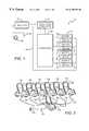
- FIG. 1is a block diagram of a sequential charging circuit according to the present invention.
- FIG. 2is a perspective view of an exemplary embodiment of the circuit of FIG. 1 .
- FIG. 3is a plan view of a first alternative embodiment of the circuit of FIG. 1 .
- FIG. 4is a plan view of a second alternative embodiment of the circuit of FIG. 1 .
- FIG. 5is a plan view of a third alternative embodiment of the circuit of FIG. 1 .
- a circuit 10comprises an AC power source 20 , a rectifier 30 , a duty cycle modulator 40 , a distributor 50 , a plurality of conductors 62 , 64 , 66 and 68 connecting the distributor 50 to one terminal of each of a plurality of batteries 72 , 74 , 76 and 78 , respectively, and a common conductor 80 which connects another terminal of each of the batteries 72 , 74 , 76 and 78 back to the rectifier, thus completing the circuit.
- the AC power source 20is presently contemplated to provide ordinary 110 Volt or 220 Volt, 60 Hz current. This is the current normally available in homes and commercial establishments such as golf courses. Other currents can also be used, however, including three-phase currents, and other voltages and frequencies available through the world.
- AC power source 20is connected to the rectifier 30 via power cord 25 .
- the rectifier 30is also contemplated to be conventional, although the claimed subject matter is not limited by type of rectifier. Indeed, it possible to eliminate the rectifier entirely by using a DC power source, or by directly splitting up alternating current cycles into appropriate pulses.
- the duty cycle modulator 40provides charging, and preferably also discharging pulses, to the batteries 62 - 68 .
- the pulsescan be provided using any number of different frequencies, voltages, waveforms, or combinations of frequencies, voltages and waveforms, and any device which can accomplish this task is contemplated to be included herein.
- the duty cycle modulator 40uses pulse width modulation (PWM) of square or triangular waves to vary the duty cycle.
- PWMpulse width modulation
- the duty cycle modulator 40is capable of modifying the respective widths of the charge and discharge pulses at least every 1.5 seconds, and the relative energy provided by the forward (charging) and reverse (discharging) pulses is determined through look-up tables or algorithms to match the characteristics of the individual battery or batteries being charged.
- Parameters for such look-up tables or algorithmsmay include 0 th order parameters such as battery temperature, loaded and unloaded battery voltage and internal battery resistance, along with first and higher order derivatives of these parameters, and combinations of both 0 th and higher order parameters.
- a thermocouplemay be included within the batteries, applied externally to the batteries, or coupled to the conductors 62 - 68 and 80 at the battery terminals. It is presently contemplated that for most types of batteries, forward pulses will be on the order of seconds, while reverse pulses will be on the order of milliseconds.
- An especially preferred modulator 40is set forth in U.S. Pat. No. 5,739,672 to Lane (Apr. 14, 1998).
- the distributor 50sequentially directs current to batteries 72 - 78 using electromechanical, solid state or other technologies. There are several options here, one of which is to fully charge each battery 72 - 78 in sequence before beginning the charging of the next battery. This first option is desirable in that the duty cycle modulator 40 need only keep track of charging parameters for the single battery being charged.
- the charging sequencewould be 72 , then 74 , then 76 , and finally 78 .
- Another optionis to charge the batteries using several sequential charging cycles.
- batteries 72 - 78may be sequentially charged (i.e, 72 , then 74 , then 76 , then 78 ) approximately 10% each during a first charging cycle, then another 10% during another charging cycle, and so forth.
- This optionhas the advantage of providing at least some charge to many batteries where there is insufficient time to fully charge all of the batteries.
- FIG. 2six golf carts 101 - 106 are connected to a single charger 110 through cables 161 - 166 in a “line” configuration.
- the charger 110includes components having the functions of the rectifier 30 , duty cycle modulator 40 and distributor 50 described above, and is connected to a power outlet 120 via power cord 125 .
- a greater or lesser number of golf carts or other battery operated devicescould be connected to the charger in a similar manner.
- the number of golf carts sequentially charged by a single charger as disclosed hereincould be three, five, seven or ten.
- the six golf carts 101 - 106are connected to charger 110 through cables 161 - 166 in a “circle” configuration.
- the six golf carts 101 - 106are connected to charger 110 through cables 161 A- 166 A in an “H” configuration.
- carts 101 - 103(technically the batteries in carts 101 - 103 ) are all charged together (in parallel as a first group, and carts 104 - 1063 are all charged together (in parallel) as a second group.
- the six golf carts 101 - 106are connected to charger 110 through cables 161 B- 166 B in a “modified line” configuration, such that carts 101 - 102 are charged together (in parallel) as a first group, carts 103 - 104 are charged together (in parallel) as a second group, and while carts 103 - 104 are charged together (in parallel) as a second group.
Landscapes
- Engineering & Computer Science (AREA)
- Power Engineering (AREA)
- Transportation (AREA)
- Mechanical Engineering (AREA)
- Charge And Discharge Circuits For Batteries Or The Like (AREA)
- Secondary Cells (AREA)
Abstract
Description
Claims (11)
Priority Applications (3)
| Application Number | Priority Date | Filing Date | Title |
|---|---|---|---|
| US09/131,428US6198251B1 (en) | 1997-06-03 | 1998-08-10 | Method for sequentially charging batteries in situ |
| PCT/US1999/016924WO2000010239A1 (en) | 1998-08-10 | 1999-07-27 | METHOD AND APPARATUS FOR SEQUENTIALLY CHARGING BATTERIES $i(IN SITU) |
| AU51307/99AAU5130799A (en) | 1998-08-10 | 1999-07-27 | Method and apparatus for sequentially charging batteries (in situ) |
Applications Claiming Priority (2)
| Application Number | Priority Date | Filing Date | Title |
|---|---|---|---|
| US86846597A | 1997-06-03 | 1997-06-03 | |
| US09/131,428US6198251B1 (en) | 1997-06-03 | 1998-08-10 | Method for sequentially charging batteries in situ |
Related Parent Applications (1)
| Application Number | Title | Priority Date | Filing Date |
|---|---|---|---|
| US86846597AContinuation-In-Part | 1997-06-03 | 1997-06-03 |
Publications (1)
| Publication Number | Publication Date |
|---|---|
| US6198251B1true US6198251B1 (en) | 2001-03-06 |
Family
ID=22449423
Family Applications (1)
| Application Number | Title | Priority Date | Filing Date |
|---|---|---|---|
| US09/131,428Expired - Fee RelatedUS6198251B1 (en) | 1997-06-03 | 1998-08-10 | Method for sequentially charging batteries in situ |
Country Status (3)
| Country | Link |
|---|---|
| US (1) | US6198251B1 (en) |
| AU (1) | AU5130799A (en) |
| WO (1) | WO2000010239A1 (en) |
Cited By (29)
| Publication number | Priority date | Publication date | Assignee | Title |
|---|---|---|---|---|
| US6476572B2 (en)* | 2001-04-03 | 2002-11-05 | Overhead Door Corporation | Power supply system and method for dock equipment |
| US20040108835A1 (en)* | 2002-12-02 | 2004-06-10 | Lg Electronics Inc. | Method and apparatus to charge a plurality of batteries |
| US20050001593A1 (en)* | 2003-05-30 | 2005-01-06 | Atsushi Kawasumi | Method of charging and discharging a plurality of batteries |
| US20050258798A1 (en)* | 2000-11-09 | 2005-11-24 | Karl Meier-Engel | Battery charging device and method for the charging of batteries with several battery blocks |
| US20050271555A1 (en)* | 2004-04-07 | 2005-12-08 | Ids Co., Ltd. | Self-running sample holder and system having self-running sample holders |
| US7193393B1 (en)* | 2001-10-26 | 2007-03-20 | Payne James C | Approach for charging multiple batteries |
| WO2010049773A3 (en)* | 2008-10-28 | 2010-06-24 | Panasonic Electric Works Co., Ltd. | Charging cable unit |
| US20110029144A1 (en)* | 2009-07-28 | 2011-02-03 | Michael Muller | Plug-In Electric Vehicle Supply Equipment |
| US20110043168A1 (en)* | 2006-07-17 | 2011-02-24 | O2Micro International Limited | Monitoring battery cell voltage |
| US20110144823A1 (en)* | 2009-07-28 | 2011-06-16 | Michael Muller | Sequential Charging of Multiple Electric Vehicles |
| GB2479418A (en)* | 2010-04-10 | 2011-10-12 | Computerized Electricity Systems Ltd | Centralized charging system for electric vehicles |
| WO2011127446A3 (en)* | 2010-04-09 | 2011-12-01 | Aerovironment, Inc. | Portable charging cable with in-line controller |
| US20120139335A1 (en)* | 2010-12-02 | 2012-06-07 | Hydrive Vehicles, Incorporated | System for extracting electrical power from an electric vehicle |
| JP2012147555A (en)* | 2011-01-11 | 2012-08-02 | Full Time System:Kk | Electric vehicle charging device |
| WO2012123933A1 (en)* | 2011-03-14 | 2012-09-20 | Nachman David | Methods and devices for cell-by-cell charging of battery cells connected in a row |
| US8307967B2 (en) | 2007-07-04 | 2012-11-13 | Satyajit Patwardhan | Widely deployable charging system for vehicles |
| US20130321024A1 (en)* | 2012-05-31 | 2013-12-05 | Service Solutions U.S. Llc | Plug-in electric vehicle supply equipment having a process and device for circuit testing |
| US8624719B2 (en) | 2011-06-03 | 2014-01-07 | Bosch Automotive Service Solutions Llc | Smart phone control and notification for an electric vehicle charging station |
| US8725330B2 (en) | 2010-06-02 | 2014-05-13 | Bryan Marc Failing | Increasing vehicle security |
| US8854003B2 (en) | 2012-05-21 | 2014-10-07 | The United States Of America As Represented By The Secretary Of The Army | Technique for rapid battery capacity testing |
| US8929069B2 (en) | 2012-05-31 | 2015-01-06 | Bosch Automotive Service Solutions Llc | Electric vehicle charging system with robustness features and universal port |
| US20150008888A1 (en)* | 2013-07-03 | 2015-01-08 | Schneider Electric Industries Sas | Electric charging system of a plurality of electric vehicles and method for distributing the electric power delivered by an electric power supply of such a system |
| US8988047B2 (en) | 2012-08-30 | 2015-03-24 | General Electric Company | Method of charging an electrochemical cell |
| US9054539B2 (en) | 2012-05-31 | 2015-06-09 | Bosch Automotive Service Solutions Inc. | Arrangement and process for housing electric vehicle supply equipment |
| US9121073B2 (en) | 2009-07-28 | 2015-09-01 | Bosch Automotive Service Solutions Inc. | Plug-in electric vehicle supply equipment with indicators |
| CN105398345A (en)* | 2014-09-05 | 2016-03-16 | 福特全球技术公司 | Dc Fast Charge Testing Method And System For Electric Vehicles |
| EP2667480A4 (en)* | 2011-01-21 | 2017-08-16 | Nec Corporation | Charge control apparatus, charge control method, and program |
| CN110192323A (en)* | 2017-08-04 | 2019-08-30 | 株式会社船桥总行 | Power supply switching device and electric power supply system |
| US12286021B1 (en) | 2022-03-28 | 2025-04-29 | Power Tree, LLC | Suspended battery charging station |
Families Citing this family (1)
| Publication number | Priority date | Publication date | Assignee | Title |
|---|---|---|---|---|
| US9762069B2 (en)* | 2009-05-19 | 2017-09-12 | Duracell U.S. Operations, Inc. | Multi-use fast rate charging stand |
Citations (10)
| Publication number | Priority date | Publication date | Assignee | Title |
|---|---|---|---|---|
| US3928791A (en)* | 1974-05-20 | 1975-12-23 | Gen Electric | Stand-by power system |
| US5202617A (en)* | 1991-10-15 | 1993-04-13 | Norvik Technologies Inc. | Charging station for electric vehicles |
| US5206097A (en)* | 1991-06-05 | 1993-04-27 | Motorola, Inc. | Battery package having a communication window |
| US5477123A (en)* | 1994-12-12 | 1995-12-19 | Technoggin, Inc. | Connection multiple batteries to battery powered devices |
| US5481174A (en)* | 1993-12-27 | 1996-01-02 | Motorola, Inc. | Method of rapidly charging a lithium ion cell |
| US5548200A (en)* | 1994-07-06 | 1996-08-20 | Norvik Traction Inc. | Universal charging station and method for charging electric vehicle batteries |
| US5661634A (en)* | 1993-11-09 | 1997-08-26 | Fujitsu Limited | Information processing system using portable terminal unit and data communication adapter therefor |
| US5666530A (en)* | 1992-12-02 | 1997-09-09 | Compaq Computer Corporation | System for automatic synchronization of common file between portable computer and host computer via communication channel selected from a plurality of usable channels there between |
| US5933812A (en)* | 1995-04-12 | 1999-08-03 | Verifone Inc. | Portable transaction terminal system |
| US5966285A (en)* | 1997-06-06 | 1999-10-12 | Compaq Computer Corporation | Mobile portable computer docking/office station |
- 1998
- 1998-08-10USUS09/131,428patent/US6198251B1/ennot_activeExpired - Fee Related
- 1999
- 1999-07-27AUAU51307/99Apatent/AU5130799A/ennot_activeAbandoned
- 1999-07-27WOPCT/US1999/016924patent/WO2000010239A1/enactiveApplication Filing
Patent Citations (11)
| Publication number | Priority date | Publication date | Assignee | Title |
|---|---|---|---|---|
| US3928791A (en)* | 1974-05-20 | 1975-12-23 | Gen Electric | Stand-by power system |
| US5206097A (en)* | 1991-06-05 | 1993-04-27 | Motorola, Inc. | Battery package having a communication window |
| US5202617A (en)* | 1991-10-15 | 1993-04-13 | Norvik Technologies Inc. | Charging station for electric vehicles |
| US5666530A (en)* | 1992-12-02 | 1997-09-09 | Compaq Computer Corporation | System for automatic synchronization of common file between portable computer and host computer via communication channel selected from a plurality of usable channels there between |
| US5661634A (en)* | 1993-11-09 | 1997-08-26 | Fujitsu Limited | Information processing system using portable terminal unit and data communication adapter therefor |
| US5481174A (en)* | 1993-12-27 | 1996-01-02 | Motorola, Inc. | Method of rapidly charging a lithium ion cell |
| US5548200A (en)* | 1994-07-06 | 1996-08-20 | Norvik Traction Inc. | Universal charging station and method for charging electric vehicle batteries |
| US5477123A (en)* | 1994-12-12 | 1995-12-19 | Technoggin, Inc. | Connection multiple batteries to battery powered devices |
| US5621301A (en)* | 1994-12-12 | 1997-04-15 | Technoggin, Inc. | Connecting multiple batteries to battery powered devices |
| US5933812A (en)* | 1995-04-12 | 1999-08-03 | Verifone Inc. | Portable transaction terminal system |
| US5966285A (en)* | 1997-06-06 | 1999-10-12 | Compaq Computer Corporation | Mobile portable computer docking/office station |
Cited By (59)
| Publication number | Priority date | Publication date | Assignee | Title |
|---|---|---|---|---|
| US20050258798A1 (en)* | 2000-11-09 | 2005-11-24 | Karl Meier-Engel | Battery charging device and method for the charging of batteries with several battery blocks |
| US6476572B2 (en)* | 2001-04-03 | 2002-11-05 | Overhead Door Corporation | Power supply system and method for dock equipment |
| US7193393B1 (en)* | 2001-10-26 | 2007-03-20 | Payne James C | Approach for charging multiple batteries |
| US20040108835A1 (en)* | 2002-12-02 | 2004-06-10 | Lg Electronics Inc. | Method and apparatus to charge a plurality of batteries |
| US20050001593A1 (en)* | 2003-05-30 | 2005-01-06 | Atsushi Kawasumi | Method of charging and discharging a plurality of batteries |
| US20100239461A1 (en)* | 2004-04-07 | 2010-09-23 | Ids Co., Ltd. | Self-Running Sample Holder and System Having Self-Running Sample Holders |
| US20050271555A1 (en)* | 2004-04-07 | 2005-12-08 | Ids Co., Ltd. | Self-running sample holder and system having self-running sample holders |
| US20110043168A1 (en)* | 2006-07-17 | 2011-02-24 | O2Micro International Limited | Monitoring battery cell voltage |
| US8310206B2 (en)* | 2006-07-17 | 2012-11-13 | O2Micro International Limited | Monitoring battery cell voltage |
| US20110057586A1 (en)* | 2006-07-17 | 2011-03-10 | O2Micro International Limited | Monitoring battery cell voltage |
| US8294424B2 (en) | 2006-07-17 | 2012-10-23 | O2Micro International Limited | Monitoring battery cell voltage |
| US8307967B2 (en) | 2007-07-04 | 2012-11-13 | Satyajit Patwardhan | Widely deployable charging system for vehicles |
| WO2010049773A3 (en)* | 2008-10-28 | 2010-06-24 | Panasonic Electric Works Co., Ltd. | Charging cable unit |
| US8890473B2 (en)* | 2009-07-28 | 2014-11-18 | Bosch Automotive Service Solutions Llc | Sequential charging of multiple electric vehicles |
| US20110029144A1 (en)* | 2009-07-28 | 2011-02-03 | Michael Muller | Plug-In Electric Vehicle Supply Equipment |
| US8860366B2 (en) | 2009-07-28 | 2014-10-14 | Bosch Automotive Service Solutions Llc | Plug-in electric vehicle supply equipment |
| US9121073B2 (en) | 2009-07-28 | 2015-09-01 | Bosch Automotive Service Solutions Inc. | Plug-in electric vehicle supply equipment with indicators |
| US8710796B2 (en) | 2009-07-28 | 2014-04-29 | Bosch Automotive Service Solutions Llc | Electric vehicle supply equipment having a socket and a method of charging an electric vehicle |
| US20110144823A1 (en)* | 2009-07-28 | 2011-06-16 | Michael Muller | Sequential Charging of Multiple Electric Vehicles |
| US9487099B2 (en) | 2009-07-28 | 2016-11-08 | Bosch Automotive Service Solutions Inc. | Plug-in electric vehicle supply equipment |
| US20110029146A1 (en)* | 2009-07-28 | 2011-02-03 | Michael Muller | Plug-In Electric Vehicle Supply Equipment |
| WO2011127446A3 (en)* | 2010-04-09 | 2011-12-01 | Aerovironment, Inc. | Portable charging cable with in-line controller |
| US9533599B2 (en) | 2010-04-09 | 2017-01-03 | Aerovironment, Inc. | Portable charging cable with in-line controller |
| US9981563B2 (en) | 2010-04-09 | 2018-05-29 | Aerovironment, Inc. | Electric vehicle supply equipment with temperature controlled current |
| US10333318B2 (en) | 2010-04-09 | 2019-06-25 | Webasto Charging Systems, Inc. | Electric vehicle supply equipment with temperature controlled current |
| US9421875B1 (en) | 2010-04-09 | 2016-08-23 | Aerovironment, Inc. | Electric vehicle supply equipment with temperature controlled current |
| US9365123B2 (en) | 2010-04-09 | 2016-06-14 | Aerovironment, Inc. | Electric vehicle supply equipment with temperature controlled current |
| US9365124B2 (en) | 2010-04-09 | 2016-06-14 | Aerovironment, Inc. | EVSE kit including a portable charging cable, an in-line EVSE controller and an interface tool |
| US10348103B2 (en) | 2010-04-09 | 2019-07-09 | Webasto Charging Systems, Inc. | Portable charging cable with in-line controller |
| US11292344B2 (en) | 2010-04-09 | 2022-04-05 | Webasto Charging Systems, Inc. | Portable charging cable with in-line controller |
| GB2479418A (en)* | 2010-04-10 | 2011-10-12 | Computerized Electricity Systems Ltd | Centralized charging system for electric vehicles |
| US8841881B2 (en) | 2010-06-02 | 2014-09-23 | Bryan Marc Failing | Energy transfer with vehicles |
| US11186192B1 (en) | 2010-06-02 | 2021-11-30 | Bryan Marc Failing | Improving energy transfer with vehicles |
| US9393878B1 (en) | 2010-06-02 | 2016-07-19 | Bryan Marc Failing | Energy transfer with vehicles |
| US9114719B1 (en) | 2010-06-02 | 2015-08-25 | Bryan Marc Failing | Increasing vehicle security |
| US10124691B1 (en) | 2010-06-02 | 2018-11-13 | Bryan Marc Failing | Energy transfer with vehicles |
| US8725330B2 (en) | 2010-06-02 | 2014-05-13 | Bryan Marc Failing | Increasing vehicle security |
| US20120139335A1 (en)* | 2010-12-02 | 2012-06-07 | Hydrive Vehicles, Incorporated | System for extracting electrical power from an electric vehicle |
| US8922049B2 (en)* | 2010-12-02 | 2014-12-30 | Hydrive Vehicles, Incorporated | System for extracting electrical power from an electric vehicle |
| CN103959590A (en)* | 2010-12-21 | 2014-07-30 | 博世汽车服务解决方案有限公司 | Sequential charging of multiple electric vehicles |
| CN103959590B (en)* | 2010-12-21 | 2017-03-01 | 博世汽车服务解决方案公司 | The orderly charging of multiple electric vehicles |
| WO2012088223A3 (en)* | 2010-12-21 | 2014-04-10 | Service Solutions U.S. Llc | Sequential charging of multiple electric vehicles |
| JP2012147555A (en)* | 2011-01-11 | 2012-08-02 | Full Time System:Kk | Electric vehicle charging device |
| EP2667480A4 (en)* | 2011-01-21 | 2017-08-16 | Nec Corporation | Charge control apparatus, charge control method, and program |
| WO2012123933A1 (en)* | 2011-03-14 | 2012-09-20 | Nachman David | Methods and devices for cell-by-cell charging of battery cells connected in a row |
| US8624719B2 (en) | 2011-06-03 | 2014-01-07 | Bosch Automotive Service Solutions Llc | Smart phone control and notification for an electric vehicle charging station |
| US8854003B2 (en) | 2012-05-21 | 2014-10-07 | The United States Of America As Represented By The Secretary Of The Army | Technique for rapid battery capacity testing |
| US9013206B2 (en)* | 2012-05-31 | 2015-04-21 | Bosch Automotive Service Solutions Inc. | Plug-in electric vehicle supply equipment having a process and device for circuit testing |
| US8929069B2 (en) | 2012-05-31 | 2015-01-06 | Bosch Automotive Service Solutions Llc | Electric vehicle charging system with robustness features and universal port |
| US20130321024A1 (en)* | 2012-05-31 | 2013-12-05 | Service Solutions U.S. Llc | Plug-in electric vehicle supply equipment having a process and device for circuit testing |
| US9054539B2 (en) | 2012-05-31 | 2015-06-09 | Bosch Automotive Service Solutions Inc. | Arrangement and process for housing electric vehicle supply equipment |
| US8988047B2 (en) | 2012-08-30 | 2015-03-24 | General Electric Company | Method of charging an electrochemical cell |
| US20150008888A1 (en)* | 2013-07-03 | 2015-01-08 | Schneider Electric Industries Sas | Electric charging system of a plurality of electric vehicles and method for distributing the electric power delivered by an electric power supply of such a system |
| US9586492B2 (en)* | 2013-07-03 | 2017-03-07 | Schneider Electric Industries Sas | Electric charging system of a plurality of electric vehicles and method for distributing the electric power delivered by an electric power supply of such a system |
| CN105398345A (en)* | 2014-09-05 | 2016-03-16 | 福特全球技术公司 | Dc Fast Charge Testing Method And System For Electric Vehicles |
| CN105398345B (en)* | 2014-09-05 | 2020-01-21 | 福特全球技术公司 | Direct current quick charge test method and system for electric vehicle |
| CN110192323A (en)* | 2017-08-04 | 2019-08-30 | 株式会社船桥总行 | Power supply switching device and electric power supply system |
| EP3561747A4 (en)* | 2017-08-04 | 2019-12-18 | Kabushiki Kaisha Funabashi Soukou | POWER SUPPLY SWITCHING DEVICE AND SYSTEM |
| US12286021B1 (en) | 2022-03-28 | 2025-04-29 | Power Tree, LLC | Suspended battery charging station |
Also Published As
| Publication number | Publication date |
|---|---|
| AU5130799A (en) | 2000-03-06 |
| WO2000010239A1 (en) | 2000-02-24 |
Similar Documents
| Publication | Publication Date | Title |
|---|---|---|
| US6198251B1 (en) | Method for sequentially charging batteries in situ | |
| CN213185534U (en) | Power equipment | |
| US4309644A (en) | Electric vehicle controller adapted for charge station connection | |
| US5479083A (en) | Non-dissipative battery charger equalizer | |
| US5998968A (en) | Method and apparatus for rapidly charging and reconditioning a battery | |
| EP0348983B1 (en) | Method of charging and discharging battery and power source apparatus adopting the same | |
| US8378632B2 (en) | Circuit arrangement with multiple batteries | |
| US6462511B1 (en) | Pseudo-parallel charging systems and methods | |
| US3928791A (en) | Stand-by power system | |
| US5710504A (en) | Switched capacitor system for automatic battery equalization | |
| CA1072631A (en) | Charging system and method for multicell storage batteries | |
| KR101124800B1 (en) | Charge Equalization Apparatus | |
| US6043629A (en) | Modular control electronics for batteries | |
| US3930192A (en) | Stand-by power system | |
| US6040684A (en) | Lithium ion fast pulse charger | |
| US4101787A (en) | Electrical power supply | |
| US20030117109A1 (en) | Parallel battery charging device | |
| US8598845B2 (en) | Battery chargers, electrical systems, and rechargeable battery charging methods | |
| US5739672A (en) | Method and apparatus for charging batteries | |
| EP1223653A4 (en) | Electric device and apparatus for charging battery unit, and method for charging and discharging | |
| RU2003130375A (en) | ENERGY STORAGE DEVICE FOR VARIABLE LOADS | |
| US6242889B1 (en) | Combination battery charger/controller | |
| US11710978B2 (en) | Battery charger and method for charging a battery | |
| US11342761B2 (en) | Battery fleet charging system | |
| KR100397481B1 (en) | How to reduce internal resistance of rechargeable batteries |
Legal Events
| Date | Code | Title | Description |
|---|---|---|---|
| FPAY | Fee payment | Year of fee payment:4 | |
| AS | Assignment | Owner name:FLUOR TECHNOLGIES CORPORATION, CALIFORNIA Free format text:ASSIGNMENT OF ASSIGNORS INTEREST;ASSIGNOR:FLUOR ENTERPRISES, INC.;REEL/FRAME:015541/0783 Effective date:20040101 Owner name:FLUOR ENTERPRISES, INC., CALIFORNIA Free format text:ASSIGNMENT OF ASSIGNORS INTEREST;ASSIGNOR:FLUOR CORPORATION;REEL/FRAME:015552/0248 Effective date:20041130 Owner name:FLUOR ENTERPRISES, INC.,CALIFORNIA Free format text:ASSIGNMENT OF ASSIGNORS INTEREST;ASSIGNOR:FLUOR CORPORATION;REEL/FRAME:015552/0248 Effective date:20041130 Owner name:FLUOR TECHNOLGIES CORPORATION,CALIFORNIA Free format text:ASSIGNMENT OF ASSIGNORS INTEREST;ASSIGNOR:FLUOR ENTERPRISES, INC.;REEL/FRAME:015541/0783 Effective date:20040101 | |
| REMI | Maintenance fee reminder mailed | ||
| LAPS | Lapse for failure to pay maintenance fees | ||
| STCH | Information on status: patent discontinuation | Free format text:PATENT EXPIRED DUE TO NONPAYMENT OF MAINTENANCE FEES UNDER 37 CFR 1.362 | |
| FP | Lapsed due to failure to pay maintenance fee | Effective date:20090306 |