US6198054B1 - Multiple electric switch with single actuating lever - Google Patents
Multiple electric switch with single actuating leverDownload PDFInfo
- Publication number
- US6198054B1 US6198054B1US09/546,165US54616500AUS6198054B1US 6198054 B1US6198054 B1US 6198054B1US 54616500 AUS54616500 AUS 54616500AUS 6198054 B1US6198054 B1US 6198054B1
- Authority
- US
- United States
- Prior art keywords
- lever
- switch
- lying
- housing
- axis
- Prior art date
- Legal status (The legal status is an assumption and is not a legal conclusion. Google has not performed a legal analysis and makes no representation as to the accuracy of the status listed.)
- Expired - Fee Related
Links
Images


Classifications
- H—ELECTRICITY
- H01—ELECTRIC ELEMENTS
- H01H—ELECTRIC SWITCHES; RELAYS; SELECTORS; EMERGENCY PROTECTIVE DEVICES
- H01H25/00—Switches with compound movement of handle or other operating part
- H01H25/06—Operating part movable both angularly and rectilinearly, the rectilinear movement being along the axis of angular movement
- H—ELECTRICITY
- H01—ELECTRIC ELEMENTS
- H01H—ELECTRIC SWITCHES; RELAYS; SELECTORS; EMERGENCY PROTECTIVE DEVICES
- H01H25/00—Switches with compound movement of handle or other operating part
- H01H25/04—Operating part movable angularly in more than one plane, e.g. joystick
- H01H25/041—Operating part movable angularly in more than one plane, e.g. joystick having a generally flat operating member depressible at different locations to operate different controls
- H01H2025/046—Operating part movable angularly in more than one plane, e.g. joystick having a generally flat operating member depressible at different locations to operate different controls having a spherical bearing between operating member and housing or bezel
- H—ELECTRICITY
- H01—ELECTRIC ELEMENTS
- H01H—ELECTRIC SWITCHES; RELAYS; SELECTORS; EMERGENCY PROTECTIVE DEVICES
- H01H25/00—Switches with compound movement of handle or other operating part
- H01H25/04—Operating part movable angularly in more than one plane, e.g. joystick
- H01H2025/048—Operating part movable angularly in more than one plane, e.g. joystick having a separate central push, slide or tumbler button which is not integral with the operating part that surrounds it
- H—ELECTRICITY
- H01—ELECTRIC ELEMENTS
- H01H—ELECTRIC SWITCHES; RELAYS; SELECTORS; EMERGENCY PROTECTIVE DEVICES
- H01H25/00—Switches with compound movement of handle or other operating part
- H01H25/008—Operating part movable both angularly and rectilinearly, the rectilinear movement being perpendicular to the axis of angular movement
Definitions
- a multiple switch arrangementwhich enables operation of multiple switches by manipulation of a single lever or other actuator, in a construction that is very compact to occupy a minimum area of a circuit board and which is of simple and low cost construction.
- the switch arrangementincludes an actuating lever lying along a primarily vertical axis and pivotable about horizontal axes.
- the leverhas a first arm that extends West from the axis and a second arm that extends South from the axis.
- a pair of West switcheslies West of the axis, including upper and lower West switches lying above and below the first arm.
- the upper and lower West switchesare closed by the first arm when the top of the lever is moved respectively East or West.
- at least one and preferably two South switcheslie South of the axis, to be closed when the top of the lever is moved North or South.
- Each of the upper switchesincludes a bowed upper trip member whose middle can be deflected upwardly to close the switch, while each lower switch includes a lower trip member whose middle can be deflected down to close the lower switch.
- Each arm that extends from the leverhas an arm end that lies between the bowed middle portions of the upper and lower trip members. The end of each arm preferably has upper and lower projections to apply concentrated forces to the middle portions of the trip members to more easily deflect them.
- the leverhas a spherical body lying in a spherical recess formed in the housing.
- the bodyhas a vertical passage, and a plunger is slideably mounted in the passage and can be depressed to depress the middle portion of a trip member lying under the plunger.
- the housingis preferably formed with upper and lower housing parts that each forms part of a cavity to form cavities between the housing parts.
- the upper and lower switcheslie at the top and bottom of the cavities.
- An independent switch contact of each upper switchhas a tail that extends to the outside of the housing and down along part of the upper housing part and down along all of the lower housing part and which has a lower end positioned to engage a trace on a circuit board on which the assembly is mounted.
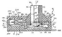
- FIG. 1is an exploded isometric view showing the main components of a multiple electric switch assembly of the present invention.
- FIG. 2is a plan view of the assembled switch assembly of FIG. 1 .
- FIG. 3is a side elevation view of the switch assembly of FIG. 2 .
- FIG. 4is a front elevation view of the switch assembly of FIG. 2, shown mounted on a circuit board.
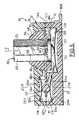
- FIG. 5is an enlarged sectional view, taken on line 5 — 5 of FIG. 2, with the switch assembly in a rest position wherein all switches are open.
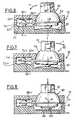
- FIG. 6is a view similar to that of FIG. 5, with the lever top pivoted to the West.
- FIG. 7is a view similar to that of FIG. 6, but with the lever top pivoted to the East.
- FIG. 8is a view similar to that of FIG. 5, but with the push button of the lever having been depressed.
- FIG. 1illustrates a multiple electrical switch apparatus 10 which includes a housing 100 with upper and lower housing parts 12 , 13 that have top and bottom faces 16 , 17 and that are joined together at adjacent faces 14 , 15 .
- An actuator lever assembly or actuator lever 50is mounted in the housing along a vertical axis V that extends in upward U and downward D directions at a center region 44 .
- the levercan pivot about a horizontal North-South axis 102 and about a perpendicular horizontal East-West axis 104 .
- the leverhas a West arm 68 W extending to the West W from the axis V, and has a South arm 68 S extending to the South S from the axis.
- the armsare designed to operate switches when the lever is pivoted.
- FIG. 5shows the lever 50 in a rest state, with none of the switches closed.
- the West arm 68 Wextends into a side cavity 42 W that is horizontally spaced from the vertical axis V of the lever, with the cavity formed by depressions in adjacent faces of the upper and lower housing halves.
- the cavityholds upper and lower switches 114 , 116 that each includes a resilient trip member or trip element 32 W, 33 W.
- the upper switchincludes an outer contact 28 W and a center contact 26 W.
- the trip member 32 Whas a periphery that engages the outer contact 28 W. However, the middle 120 of the trip member is spaced from the center contact 26 W.
- the arm 68 WWhen the top of the lever 50 is moved to the East E, the arm 68 W is raised, and a convex deflecting part 74 W on the arm pushes up the middle 120 of the trip member to deflect it against the center contact 26 W. Since the trip member is of electrically conductive material, this results in closing the upper switch 114 by the trip member engaging both the outer contact 28 W and the center contact 26 W.
- the lower switch 116is of similar construction, with a center contact 27 W and outer contact 29 W.
- the arm 68 Whas a lower convex projection 75 W that is positioned to depress the middle of the trip member 33 W against a lower center contact 27 W to close the lower switch. The lower switch is closed when the top of the lever 50 is moved to the West W.
- Each of the convex deflecting parts 74 W, 75 Whas a radius of curvature much less than half the length of a trip member 32 W, 33 W.
- FIG. 6shows the switch assembly with the top of the lever 50 moved to the West W, resulting in closing of the lower West switch 116 .
- FIG. 7shows the top 52 of the lever moved to the East, resulting in closing of the upper West switch 114 .
- FIG. 1shows that the switch assembly includes upper and lower South switches 117 , 118 that include upper and lower tripping member 32 S, 33 S, with corresponding center contacts 26 S, 27 S and outer contacts 28 S, 29 S.
- the housinghas depressions that form a cavity 22 S, 23 S in which the center and outer contacts and the tripping members lie, in the same manner as for the West switches shown in FIG. 5 .
- FIG. 5shows that the switch assembly includes a fifth switch or middle switch 122 that lies in a bottom center cavity 124 .
- the middle switchincludes a trip member or element 132 lying over an outer contact 128 and a central contact 126 .
- the leverincludes a vertical passage 58 and a lever part in the form of a plunger or push button 53 that is slideably mounted in the passage and that forms the top 52 of the lever.
- a convex projection 64 at the bottom of the push buttondepresses the middle 130 of the trip element against the center contact 126 to close the middle switch.
- FIG. 8shows the push button 50 fully depressed.
- the rest of the lever, shown in FIG. 5,includes a body 48 and the arms 68 W, 68 S that do not move down with the push button.
- the push buttonhas a shoulder 62 that press up the body 48 when the push button is not depressed.
- the switch assemblyhas five switches which can be selectively operated by a person who manipulates a location on a single element, that being the top 52 of the lever. Different switches are actuated when the top of the lever 52 is moved to the East, to the West, to the North, to the South, or is depressed to move the top of the lever down.
- FIG. 5shows that the body 48 has a spherical surface 54 that extends along part of a sphere and a bottom 56 .
- the housingincludes a spherical recess 46 which closely receives the spherical surface of the body in pivoting about the center M of the spherical surfaces.
- the surface 54 of the body, and preferably the entire body,is of a low friction material to facilitate sliding movement of the body with respect to the recess walls as the lever pivots. Such pivoting is limited to pivoting about the North-South axis and the East-West axis.
- the bodyis constructed with a metal plate 66 that extends around the vertical cruciform passage 58 in the body and that has arm cores extending along the arms 68 W, 68 S to stiffen them, with plastic overmold around each arm.
- FIG. 1shows that the lower and upper housing parts have slot parts 78 W, 79 W that form a horizontal arm passage through which the West arm 68 W extends.
- the side walls of the slot formed by the slot partskeep the West arm 68 W centered in the West cavity 42 W.
- South slot parts 78 S, 79 Sform another arm passage that positions the South arm 68 S.
- the side walls of the arm passageslimit pivoting of the lever about the vertical axis V.
- the upper and lower housing parts 12 , 13are formed of molded plastic, with the lower part having upstanding pegs 34 that fit into corresponding holes 35 in the upper housing part. After the pegs project through the holes, the upper ends of the pegs can be heat deformed to lock the housing parts together.
- Applicantprefers to connect all lower outer contacts, such as 29 W, 29 S and 128 together and to a single tail 30 A.
- Each lower center contact 27 W, 27 S and 126is an independent contact, connected to separate tail 30 B, 30 D and 30 E. All tails lie outside the housing for soldering to conductive traces on a circuit board. Each contact has a portion that is molded in the corresponding housing half.
- Upper tails 30 B, 30 C, and 30 F extending from contacts mounted on the upper housing part 12are vertically elongated, and extend down along the outside of the lower housing part 13 so the upper tails can be soldered to traces on a circuit board.
- the switch assembly 10lies on a circuit board 140 , with the bottom of the tails soldered to traces 142 on an upper face of the circuit board on which the switch assembly lies.
- the tailscan have pins at their lower ends which extend through plated holes in the circuit board.
- FIG. 2shows that the switch assembly 10 has a plane of symmetry PS, with portions on opposite sides of the plane of symmetry being mirror images of each other.
- a description of switches lying West and South of the axis Vincludes the case where the switch assembly is upside-down so the switches would appear to extend East and South of the axis V.
- FIG. 1shows that the trip member 132 that lies under the push button of the lever, is in the form of an upwardly bowed dome.
- the domesnaps down, to not only close the switch but to provide a tactile feedback.
- the four trip members of the four other switchescan be made dome shaped to also snap when deflected, to provide tactile feedback, although feedback can be provided on a screen, by the changing of an image corresponding to the particular switch that is operated.
- Applicant's switchis compact, and occupies a minimum space on the circuit board. This is because there are only West and South extensions of the middle of the switch assembly, to accommodate the two West and two South switches. Additional extensions are not required to the East or to the North. This is important in applications such as on a mobile phone, where there is little space available on the circuit board for the multiple switch arrangement. This arrangement also minimizes the size of the switch.
- a mirror image switch assemblycan be constructed, with switches lying South and East of the vertical axis, or with the switch assembly turned about the vertical axis.
- the inventionprovides a multiple switch arrangement that allows each of a plurality of switches to be actuated (closed or opened) by manipulation of a single lever, where the arrangement is compact and of easily manufactured design, with a minimum number of parts and with the parts easily held in place.
- the arrangementincludes an actuating lever lying in a housing along a vertical axis, and pivotable about a horizontal East-West axis and about a perpendicular horizontal North-South axis.
- a pair of upper and lower switchesare spaced from the vertical axis along the East-West axis, and another pair of upper and lower switches are spaced from the vertical axis along the North-South axis.
- the leverincludes a body with a part spherical surface that can pivot within a part spherical recess in the housing.
- the leveralso includes a plunger or push button, that can be depressed to operate a fifth switch.
Landscapes
- Switches With Compound Operations (AREA)
Abstract
Description
Claims (12)
Applications Claiming Priority (3)
| Application Number | Priority Date | Filing Date | Title |
|---|---|---|---|
| FR9713089 | 1997-10-20 | ||
| FR9713089AFR2770022B1 (en) | 1997-10-20 | 1997-10-20 | MULTIPLE ELECTRIC SWITCH WITH SINGLE OPERATION LEVER |
| PCT/FR1998/002239WO1999021202A1 (en) | 1997-10-20 | 1998-10-19 | Multiple electric switch with single actuating lever |
Related Parent Applications (1)
| Application Number | Title | Priority Date | Filing Date |
|---|---|---|---|
| PCT/FR1998/002239Continuation-In-PartWO1999021202A1 (en) | 1997-10-20 | 1998-10-19 | Multiple electric switch with single actuating lever |
Publications (1)
| Publication Number | Publication Date |
|---|---|
| US6198054B1true US6198054B1 (en) | 2001-03-06 |
Family
ID=9512410
Family Applications (1)
| Application Number | Title | Priority Date | Filing Date |
|---|---|---|---|
| US09/546,165Expired - Fee RelatedUS6198054B1 (en) | 1997-10-20 | 2000-04-11 | Multiple electric switch with single actuating lever |
Country Status (8)
| Country | Link |
|---|---|
| US (1) | US6198054B1 (en) |
| EP (1) | EP1025572B1 (en) |
| JP (1) | JP2001521265A (en) |
| KR (1) | KR20010015683A (en) |
| CN (1) | CN1270699A (en) |
| DE (1) | DE69811106T2 (en) |
| FR (1) | FR2770022B1 (en) |
| WO (1) | WO1999021202A1 (en) |
Cited By (43)
| Publication number | Priority date | Publication date | Assignee | Title |
|---|---|---|---|---|
| US20020101402A1 (en)* | 2001-01-29 | 2002-08-01 | Yu Yat Shun | Two-axis ball-based cursor control apparatus with tactile feedback |
| US6760008B2 (en) | 2001-01-29 | 2004-07-06 | Vtech Communications Ltd. | Two-axis ball-based cursor control apparatus with magnetic force induced tactile feedback |
| US6771992B1 (en)* | 1998-07-03 | 2004-08-03 | Fujitsu Limited | Portable telephone |
| US6839051B2 (en) | 2001-01-29 | 2005-01-04 | Vtech Communications, Ltd. | Two-axis cursor control apparatus |
| US20050052425A1 (en)* | 2003-08-18 | 2005-03-10 | Zadesky Stephen Paul | Movable touch pad with added functionality |
| US20050110768A1 (en)* | 2003-11-25 | 2005-05-26 | Greg Marriott | Touch pad for handheld device |
| US20050259069A1 (en)* | 2004-05-21 | 2005-11-24 | Interlink Electronics, Inc. | Force sensing pointing device with click function |
| US20060032680A1 (en)* | 2004-08-16 | 2006-02-16 | Fingerworks, Inc. | Method of increasing the spatial resolution of touch sensitive devices |
| US20060181517A1 (en)* | 2005-02-11 | 2006-08-17 | Apple Computer, Inc. | Display actuator |
| US20070052044A1 (en)* | 2005-09-06 | 2007-03-08 | Larry Forsblad | Scrolling input arrangements using capacitive sensors on a flexible membrane |
| US20070080952A1 (en)* | 2005-10-11 | 2007-04-12 | Brian Lynch | Center button isolation ring |
| US20070083822A1 (en)* | 2001-10-22 | 2007-04-12 | Apple Computer, Inc. | Method and apparatus for use of rotational user inputs |
| US20070085841A1 (en)* | 2001-10-22 | 2007-04-19 | Apple Computer, Inc. | Method and apparatus for accelerated scrolling |
| US20070152977A1 (en)* | 2005-12-30 | 2007-07-05 | Apple Computer, Inc. | Illuminated touchpad |
| US20070152983A1 (en)* | 2005-12-30 | 2007-07-05 | Apple Computer, Inc. | Touch pad with symbols based on mode |
| US20070160353A1 (en)* | 2005-11-04 | 2007-07-12 | Credo Technology Corporation | Drill with solid state speed control and method of operating |
| US20070276525A1 (en)* | 2002-02-25 | 2007-11-29 | Apple Inc. | Touch pad for handheld device |
| US20070279394A1 (en)* | 2006-06-02 | 2007-12-06 | Apple Computer, Inc. | Techniques for interactive input to portable electronic devices |
| US20080006453A1 (en)* | 2006-07-06 | 2008-01-10 | Apple Computer, Inc., A California Corporation | Mutual capacitance touch sensing device |
| US20080006454A1 (en)* | 2006-07-10 | 2008-01-10 | Apple Computer, Inc. | Mutual capacitance touch sensing device |
| US20080007533A1 (en)* | 2006-07-06 | 2008-01-10 | Apple Computer, Inc., A California Corporation | Capacitance sensing electrode with integrated I/O mechanism |
| US20080087476A1 (en)* | 2006-10-11 | 2008-04-17 | Apple Inc. | Sensor configurations in a user input device |
| US20080088582A1 (en)* | 2006-10-11 | 2008-04-17 | Apple Inc. | Gimballed scroll wheel |
| US20080088600A1 (en)* | 2006-10-11 | 2008-04-17 | Apple Inc. | Method and apparatus for implementing multiple push buttons in a user input device |
| US20080094352A1 (en)* | 2001-10-22 | 2008-04-24 | Tsuk Robert W | Method and Apparatus for Accelerated Scrolling |
| US20080111795A1 (en)* | 2006-11-13 | 2008-05-15 | Apple Inc. | Method of capacitively sensing finger position |
| US20090020343A1 (en)* | 2007-07-17 | 2009-01-22 | Apple Inc. | Resistive force sensor with capacitive discrimination |
| US20090058687A1 (en)* | 2007-09-04 | 2009-03-05 | Apple Inc. | Compact input device |
| US20090058801A1 (en)* | 2007-09-04 | 2009-03-05 | Apple Inc. | Fluid motion user interface control |
| US20090073130A1 (en)* | 2007-09-17 | 2009-03-19 | Apple Inc. | Device having cover with integrally formed sensor |
| US20090141046A1 (en)* | 2007-12-03 | 2009-06-04 | Apple Inc. | Multi-dimensional scroll wheel |
| US20090179854A1 (en)* | 2008-01-11 | 2009-07-16 | Apple Inc. | Dynamic input graphic display |
| US20090197059A1 (en)* | 2008-02-01 | 2009-08-06 | Apple Inc. | Co-extruded materials and methods |
| US20090273573A1 (en)* | 2006-07-06 | 2009-11-05 | Apple Inc. | Mutual capacitance touch sensing device |
| US20100149127A1 (en)* | 2008-12-17 | 2010-06-17 | Apple Inc. | Integrated contact switch and touch sensor elements |
| US7795553B2 (en) | 2006-09-11 | 2010-09-14 | Apple Inc. | Hybrid button |
| US20100289759A1 (en)* | 2009-05-15 | 2010-11-18 | Apple Inc. | Input device with optimized capacitive sensing |
| US20110005845A1 (en)* | 2009-07-07 | 2011-01-13 | Apple Inc. | Touch sensing device having conductive nodes |
| US20110063139A1 (en)* | 2009-09-15 | 2011-03-17 | Joy Mm Delaware, Inc. | explosion proof electro-mechanical joystick |
| CN101055809B (en)* | 2006-04-11 | 2011-11-16 | 联合活跃技术公司 | Electric commutator with multiple switch ways |
| US8683378B2 (en) | 2007-09-04 | 2014-03-25 | Apple Inc. | Scrolling techniques for user interfaces |
| US8816967B2 (en) | 2008-09-25 | 2014-08-26 | Apple Inc. | Capacitive sensor having electrodes arranged on the substrate and the flex circuit |
| US9454256B2 (en) | 2008-03-14 | 2016-09-27 | Apple Inc. | Sensor configurations of an input device that are switchable based on mode |
Families Citing this family (5)
| Publication number | Priority date | Publication date | Assignee | Title |
|---|---|---|---|---|
| FR2770022B1 (en)* | 1997-10-20 | 1999-12-03 | Itt Mfg Enterprises Inc | MULTIPLE ELECTRIC SWITCH WITH SINGLE OPERATION LEVER |
| JP4330704B2 (en)* | 1999-06-21 | 2009-09-16 | シチズン電子株式会社 | Multi-directional switch |
| FR2820543B1 (en)* | 2001-02-02 | 2003-03-21 | Itt Mfg Enterprises Inc | MULTIPLE ELECTRICAL CONNECTOR WITH THREE MAIN SWITCHING WAYS AND A MONOBLOCK ACTUATOR |
| JP4010846B2 (en)* | 2002-03-29 | 2007-11-21 | 富士通日立プラズマディスプレイ株式会社 | Front display film for flat display panel and flat display device using the same, front film for plasma display panel and plasma display device using the same |
| JP2007087671A (en)* | 2005-09-20 | 2007-04-05 | Omron Corp | Switching device |
Citations (11)
| Publication number | Priority date | Publication date | Assignee | Title |
|---|---|---|---|---|
| GB837964A (en)* | 1957-10-14 | 1960-06-15 | Mason Electric Corp | Snap-action electric switch |
| GB2046022A (en)* | 1979-03-14 | 1980-11-05 | Shelton G G | Electric switches |
| US4756205A (en)* | 1987-02-02 | 1988-07-12 | Alinabal, Inc. | Gear shifter for manual transmission systems |
| US4767901A (en)* | 1984-12-21 | 1988-08-30 | Simmons-Rand Corporation | Process for making an enclosure outlet connection device |
| EP0623942A1 (en)* | 1993-04-20 | 1994-11-09 | FRITZ HARTMANN GERÄTEBAU GMBH & CO KG | Encoder |
| US5412164A (en)* | 1993-12-03 | 1995-05-02 | General Motors Corporation | Dual action switch assembly with sequentially actuated membrane switches including a reciprocating circuit board |
| DE4409108A1 (en)* | 1994-03-17 | 1995-09-28 | Kostal Leopold Gmbh & Co Kg | Electric four-way switch |
| US5622254A (en)* | 1996-04-18 | 1997-04-22 | Packard Hughes Interconnect Company | Two-position latching two dome switch |
| US5667061A (en)* | 1996-07-01 | 1997-09-16 | Packard Hughes Interconnect Company | Linear cam-assisted plunger switch |
| WO1999021202A1 (en)* | 1997-10-20 | 1999-04-29 | Itt Manufacturing Enterprises, Inc. | Multiple electric switch with single actuating lever |
| US5952628A (en)* | 1997-02-25 | 1999-09-14 | Matsushita Electric Industrial Co., Ltd. | Multiple-way electronic component with push switch |
- 1997
- 1997-10-20FRFR9713089Apatent/FR2770022B1/ennot_activeExpired - Fee Related
- 1998
- 1998-10-19WOPCT/FR1998/002239patent/WO1999021202A1/ennot_activeApplication Discontinuation
- 1998-10-19JPJP2000517430Apatent/JP2001521265A/ennot_activeWithdrawn
- 1998-10-19EPEP98950157Apatent/EP1025572B1/ennot_activeExpired - Lifetime
- 1998-10-19DEDE69811106Tpatent/DE69811106T2/ennot_activeExpired - Lifetime
- 1998-10-19CNCN98809183Apatent/CN1270699A/enactivePending
- 1998-10-19KRKR1020007003526Apatent/KR20010015683A/ennot_activeWithdrawn
- 2000
- 2000-04-11USUS09/546,165patent/US6198054B1/ennot_activeExpired - Fee Related
Patent Citations (11)
| Publication number | Priority date | Publication date | Assignee | Title |
|---|---|---|---|---|
| GB837964A (en)* | 1957-10-14 | 1960-06-15 | Mason Electric Corp | Snap-action electric switch |
| GB2046022A (en)* | 1979-03-14 | 1980-11-05 | Shelton G G | Electric switches |
| US4767901A (en)* | 1984-12-21 | 1988-08-30 | Simmons-Rand Corporation | Process for making an enclosure outlet connection device |
| US4756205A (en)* | 1987-02-02 | 1988-07-12 | Alinabal, Inc. | Gear shifter for manual transmission systems |
| EP0623942A1 (en)* | 1993-04-20 | 1994-11-09 | FRITZ HARTMANN GERÄTEBAU GMBH & CO KG | Encoder |
| US5412164A (en)* | 1993-12-03 | 1995-05-02 | General Motors Corporation | Dual action switch assembly with sequentially actuated membrane switches including a reciprocating circuit board |
| DE4409108A1 (en)* | 1994-03-17 | 1995-09-28 | Kostal Leopold Gmbh & Co Kg | Electric four-way switch |
| US5622254A (en)* | 1996-04-18 | 1997-04-22 | Packard Hughes Interconnect Company | Two-position latching two dome switch |
| US5667061A (en)* | 1996-07-01 | 1997-09-16 | Packard Hughes Interconnect Company | Linear cam-assisted plunger switch |
| US5952628A (en)* | 1997-02-25 | 1999-09-14 | Matsushita Electric Industrial Co., Ltd. | Multiple-way electronic component with push switch |
| WO1999021202A1 (en)* | 1997-10-20 | 1999-04-29 | Itt Manufacturing Enterprises, Inc. | Multiple electric switch with single actuating lever |
Non-Patent Citations (1)
| Title |
|---|
| PCT Search Report, WO99/21202 (PCT/FR98/02239), published Apr. 29, 1999, 3 pages.* |
Cited By (104)
| Publication number | Priority date | Publication date | Assignee | Title |
|---|---|---|---|---|
| US6771992B1 (en)* | 1998-07-03 | 2004-08-03 | Fujitsu Limited | Portable telephone |
| US6937228B2 (en) | 2001-01-29 | 2005-08-30 | Vtech Telecommunications Ltd., | Two-axis ball-based cursor control apparatus with tactile feedback |
| US6760008B2 (en) | 2001-01-29 | 2004-07-06 | Vtech Communications Ltd. | Two-axis ball-based cursor control apparatus with magnetic force induced tactile feedback |
| US6839051B2 (en) | 2001-01-29 | 2005-01-04 | Vtech Communications, Ltd. | Two-axis cursor control apparatus |
| US20020101402A1 (en)* | 2001-01-29 | 2002-08-01 | Yu Yat Shun | Two-axis ball-based cursor control apparatus with tactile feedback |
| US9009626B2 (en) | 2001-10-22 | 2015-04-14 | Apple Inc. | Method and apparatus for accelerated scrolling |
| US7710393B2 (en) | 2001-10-22 | 2010-05-04 | Apple Inc. | Method and apparatus for accelerated scrolling |
| US7710409B2 (en) | 2001-10-22 | 2010-05-04 | Apple Inc. | Method and apparatus for use of rotational user inputs |
| US20080094352A1 (en)* | 2001-10-22 | 2008-04-24 | Tsuk Robert W | Method and Apparatus for Accelerated Scrolling |
| US20080098330A1 (en)* | 2001-10-22 | 2008-04-24 | Tsuk Robert W | Method and Apparatus for Accelerated Scrolling |
| US20070085841A1 (en)* | 2001-10-22 | 2007-04-19 | Apple Computer, Inc. | Method and apparatus for accelerated scrolling |
| US7710394B2 (en) | 2001-10-22 | 2010-05-04 | Apple Inc. | Method and apparatus for use of rotational user inputs |
| US8952886B2 (en) | 2001-10-22 | 2015-02-10 | Apple Inc. | Method and apparatus for accelerated scrolling |
| US9977518B2 (en) | 2001-10-22 | 2018-05-22 | Apple Inc. | Scrolling based on rotational movement |
| US20070083822A1 (en)* | 2001-10-22 | 2007-04-12 | Apple Computer, Inc. | Method and apparatus for use of rotational user inputs |
| US10353565B2 (en) | 2002-02-25 | 2019-07-16 | Apple Inc. | Input apparatus and button arrangement for handheld device |
| US20070276525A1 (en)* | 2002-02-25 | 2007-11-29 | Apple Inc. | Touch pad for handheld device |
| US20080018615A1 (en)* | 2002-02-25 | 2008-01-24 | Apple Inc. | Touch pad for handheld device |
| US8446370B2 (en) | 2002-02-25 | 2013-05-21 | Apple Inc. | Touch pad for handheld device |
| US7499040B2 (en) | 2003-08-18 | 2009-03-03 | Apple Inc. | Movable touch pad with added functionality |
| US20060250377A1 (en)* | 2003-08-18 | 2006-11-09 | Apple Computer, Inc. | Actuating user interface for media player |
| US20050052425A1 (en)* | 2003-08-18 | 2005-03-10 | Zadesky Stephen Paul | Movable touch pad with added functionality |
| US20070273671A1 (en)* | 2003-08-18 | 2007-11-29 | Zadesky Stephen P | Movable touch pad with added functionality |
| US8749493B2 (en) | 2003-08-18 | 2014-06-10 | Apple Inc. | Movable touch pad with added functionality |
| US8933890B2 (en) | 2003-11-25 | 2015-01-13 | Apple Inc. | Techniques for interactive input to portable electronic devices |
| US7495659B2 (en) | 2003-11-25 | 2009-02-24 | Apple Inc. | Touch pad for handheld device |
| US20080012837A1 (en)* | 2003-11-25 | 2008-01-17 | Apple Computer, Inc. | Touch pad for handheld device |
| US8552990B2 (en) | 2003-11-25 | 2013-10-08 | Apple Inc. | Touch pad for handheld device |
| US20080018616A1 (en)* | 2003-11-25 | 2008-01-24 | Apple Computer, Inc. | Techniques for interactive input to portable electronic devices |
| US20050110768A1 (en)* | 2003-11-25 | 2005-05-26 | Greg Marriott | Touch pad for handheld device |
| US7176889B2 (en) | 2004-05-21 | 2007-02-13 | Interlink Electronics, Inc. | Force sensing pointing device with click function |
| US20050259069A1 (en)* | 2004-05-21 | 2005-11-24 | Interlink Electronics, Inc. | Force sensing pointing device with click function |
| US20060032680A1 (en)* | 2004-08-16 | 2006-02-16 | Fingerworks, Inc. | Method of increasing the spatial resolution of touch sensitive devices |
| US7932897B2 (en) | 2004-08-16 | 2011-04-26 | Apple Inc. | Method of increasing the spatial resolution of touch sensitive devices |
| US20060181517A1 (en)* | 2005-02-11 | 2006-08-17 | Apple Computer, Inc. | Display actuator |
| US7671837B2 (en) | 2005-09-06 | 2010-03-02 | Apple Inc. | Scrolling input arrangements using capacitive sensors on a flexible membrane |
| US20080036734A1 (en)* | 2005-09-06 | 2008-02-14 | Apple Computer, Inc. | Scrolling input arrangements using capacitive sensors on a flexible membrane |
| US20070052044A1 (en)* | 2005-09-06 | 2007-03-08 | Larry Forsblad | Scrolling input arrangements using capacitive sensors on a flexible membrane |
| US20070080952A1 (en)* | 2005-10-11 | 2007-04-12 | Brian Lynch | Center button isolation ring |
| US7880729B2 (en) | 2005-10-11 | 2011-02-01 | Apple Inc. | Center button isolation ring |
| US20070160353A1 (en)* | 2005-11-04 | 2007-07-12 | Credo Technology Corporation | Drill with solid state speed control and method of operating |
| US20070152983A1 (en)* | 2005-12-30 | 2007-07-05 | Apple Computer, Inc. | Touch pad with symbols based on mode |
| US20070152977A1 (en)* | 2005-12-30 | 2007-07-05 | Apple Computer, Inc. | Illuminated touchpad |
| US8537132B2 (en) | 2005-12-30 | 2013-09-17 | Apple Inc. | Illuminated touchpad |
| US9367151B2 (en) | 2005-12-30 | 2016-06-14 | Apple Inc. | Touch pad with symbols based on mode |
| US20080018617A1 (en)* | 2005-12-30 | 2008-01-24 | Apple Computer, Inc. | Illuminated touch pad |
| CN101055809B (en)* | 2006-04-11 | 2011-11-16 | 联合活跃技术公司 | Electric commutator with multiple switch ways |
| US8059099B2 (en) | 2006-06-02 | 2011-11-15 | Apple Inc. | Techniques for interactive input to portable electronic devices |
| US20070279394A1 (en)* | 2006-06-02 | 2007-12-06 | Apple Computer, Inc. | Techniques for interactive input to portable electronic devices |
| US10359813B2 (en) | 2006-07-06 | 2019-07-23 | Apple Inc. | Capacitance sensing electrode with integrated I/O mechanism |
| US8743060B2 (en) | 2006-07-06 | 2014-06-03 | Apple Inc. | Mutual capacitance touch sensing device |
| US20090273573A1 (en)* | 2006-07-06 | 2009-11-05 | Apple Inc. | Mutual capacitance touch sensing device |
| US20080007539A1 (en)* | 2006-07-06 | 2008-01-10 | Steve Hotelling | Mutual capacitance touch sensing device |
| US9405421B2 (en) | 2006-07-06 | 2016-08-02 | Apple Inc. | Mutual capacitance touch sensing device |
| US20080006453A1 (en)* | 2006-07-06 | 2008-01-10 | Apple Computer, Inc., A California Corporation | Mutual capacitance touch sensing device |
| US20080007533A1 (en)* | 2006-07-06 | 2008-01-10 | Apple Computer, Inc., A California Corporation | Capacitance sensing electrode with integrated I/O mechanism |
| US10890953B2 (en) | 2006-07-06 | 2021-01-12 | Apple Inc. | Capacitance sensing electrode with integrated I/O mechanism |
| US9360967B2 (en) | 2006-07-06 | 2016-06-07 | Apple Inc. | Mutual capacitance touch sensing device |
| US8514185B2 (en) | 2006-07-06 | 2013-08-20 | Apple Inc. | Mutual capacitance touch sensing device |
| US8022935B2 (en) | 2006-07-06 | 2011-09-20 | Apple Inc. | Capacitance sensing electrode with integrated I/O mechanism |
| US10139870B2 (en) | 2006-07-06 | 2018-11-27 | Apple Inc. | Capacitance sensing electrode with integrated I/O mechanism |
| US20080006454A1 (en)* | 2006-07-10 | 2008-01-10 | Apple Computer, Inc. | Mutual capacitance touch sensing device |
| US8044314B2 (en) | 2006-09-11 | 2011-10-25 | Apple Inc. | Hybrid button |
| US7795553B2 (en) | 2006-09-11 | 2010-09-14 | Apple Inc. | Hybrid button |
| US20080088600A1 (en)* | 2006-10-11 | 2008-04-17 | Apple Inc. | Method and apparatus for implementing multiple push buttons in a user input device |
| US20080284742A1 (en)* | 2006-10-11 | 2008-11-20 | Prest Christopher D | Method and apparatus for implementing multiple push buttons in a user input device |
| US20080087476A1 (en)* | 2006-10-11 | 2008-04-17 | Apple Inc. | Sensor configurations in a user input device |
| US20080088597A1 (en)* | 2006-10-11 | 2008-04-17 | Apple Inc. | Sensor configurations in a user input device |
| US8274479B2 (en) | 2006-10-11 | 2012-09-25 | Apple Inc. | Gimballed scroll wheel |
| US10180732B2 (en) | 2006-10-11 | 2019-01-15 | Apple Inc. | Gimballed scroll wheel |
| US20080088596A1 (en)* | 2006-10-11 | 2008-04-17 | Apple Inc. | Gimballed scroll wheel |
| US20080088582A1 (en)* | 2006-10-11 | 2008-04-17 | Apple Inc. | Gimballed scroll wheel |
| WO2008045833A1 (en)* | 2006-10-11 | 2008-04-17 | Apple Inc. | Gimballed scroll wheel |
| US20080111795A1 (en)* | 2006-11-13 | 2008-05-15 | Apple Inc. | Method of capacitively sensing finger position |
| US8482530B2 (en) | 2006-11-13 | 2013-07-09 | Apple Inc. | Method of capacitively sensing finger position |
| US20090019949A1 (en)* | 2007-07-17 | 2009-01-22 | Apple Inc. | Resistive force sensor with capacitive discrimination |
| US9654104B2 (en) | 2007-07-17 | 2017-05-16 | Apple Inc. | Resistive force sensor with capacitive discrimination |
| US20090020343A1 (en)* | 2007-07-17 | 2009-01-22 | Apple Inc. | Resistive force sensor with capacitive discrimination |
| US20090058801A1 (en)* | 2007-09-04 | 2009-03-05 | Apple Inc. | Fluid motion user interface control |
| US7910843B2 (en) | 2007-09-04 | 2011-03-22 | Apple Inc. | Compact input device |
| US8683378B2 (en) | 2007-09-04 | 2014-03-25 | Apple Inc. | Scrolling techniques for user interfaces |
| US12159028B2 (en) | 2007-09-04 | 2024-12-03 | Apple Inc. | Scrolling techniques for user interfaces |
| US20110169667A1 (en)* | 2007-09-04 | 2011-07-14 | Apple Inc. | Compact input device |
| US20090058687A1 (en)* | 2007-09-04 | 2009-03-05 | Apple Inc. | Compact input device |
| US8330061B2 (en) | 2007-09-04 | 2012-12-11 | Apple Inc. | Compact input device |
| US10866718B2 (en) | 2007-09-04 | 2020-12-15 | Apple Inc. | Scrolling techniques for user interfaces |
| US20090073130A1 (en)* | 2007-09-17 | 2009-03-19 | Apple Inc. | Device having cover with integrally formed sensor |
| US8866780B2 (en) | 2007-12-03 | 2014-10-21 | Apple Inc. | Multi-dimensional scroll wheel |
| US20090141046A1 (en)* | 2007-12-03 | 2009-06-04 | Apple Inc. | Multi-dimensional scroll wheel |
| US8416198B2 (en) | 2007-12-03 | 2013-04-09 | Apple Inc. | Multi-dimensional scroll wheel |
| US8125461B2 (en) | 2008-01-11 | 2012-02-28 | Apple Inc. | Dynamic input graphic display |
| US20090179854A1 (en)* | 2008-01-11 | 2009-07-16 | Apple Inc. | Dynamic input graphic display |
| US8820133B2 (en) | 2008-02-01 | 2014-09-02 | Apple Inc. | Co-extruded materials and methods |
| US20090197059A1 (en)* | 2008-02-01 | 2009-08-06 | Apple Inc. | Co-extruded materials and methods |
| US9454256B2 (en) | 2008-03-14 | 2016-09-27 | Apple Inc. | Sensor configurations of an input device that are switchable based on mode |
| US8816967B2 (en) | 2008-09-25 | 2014-08-26 | Apple Inc. | Capacitive sensor having electrodes arranged on the substrate and the flex circuit |
| US8395590B2 (en) | 2008-12-17 | 2013-03-12 | Apple Inc. | Integrated contact switch and touch sensor elements |
| US20100149127A1 (en)* | 2008-12-17 | 2010-06-17 | Apple Inc. | Integrated contact switch and touch sensor elements |
| US20100289759A1 (en)* | 2009-05-15 | 2010-11-18 | Apple Inc. | Input device with optimized capacitive sensing |
| US9354751B2 (en) | 2009-05-15 | 2016-05-31 | Apple Inc. | Input device with optimized capacitive sensing |
| US20110005845A1 (en)* | 2009-07-07 | 2011-01-13 | Apple Inc. | Touch sensing device having conductive nodes |
| US8872771B2 (en) | 2009-07-07 | 2014-10-28 | Apple Inc. | Touch sensing device having conductive nodes |
| US8400342B2 (en) | 2009-09-15 | 2013-03-19 | Joy Mm Delaware, Inc. | Explosion proof electro-mechanical joystick |
| US20110063139A1 (en)* | 2009-09-15 | 2011-03-17 | Joy Mm Delaware, Inc. | explosion proof electro-mechanical joystick |
Also Published As
| Publication number | Publication date |
|---|---|
| WO1999021202A1 (en) | 1999-04-29 |
| FR2770022B1 (en) | 1999-12-03 |
| CN1270699A (en) | 2000-10-18 |
| DE69811106T2 (en) | 2003-11-13 |
| KR20010015683A (en) | 2001-02-26 |
| EP1025572B1 (en) | 2003-01-29 |
| DE69811106D1 (en) | 2003-03-06 |
| EP1025572A1 (en) | 2000-08-09 |
| FR2770022A1 (en) | 1999-04-23 |
| JP2001521265A (en) | 2001-11-06 |
Similar Documents
| Publication | Publication Date | Title |
|---|---|---|
| US6198054B1 (en) | Multiple electric switch with single actuating lever | |
| US6794589B2 (en) | Multiple electrical switch arrangement | |
| US3403236A (en) | Electrical switch having a one-piece actuator and spring arm structure | |
| US6348664B2 (en) | Multidirectional switch whose stem can be tilted and pushed | |
| KR20060113382A (en) | Slide Operated Switch | |
| JP2002033030A (en) | Key switch | |
| US5803243A (en) | Latching rocker switch | |
| US5486669A (en) | Detented paddle blade switch assembly | |
| US6657141B1 (en) | Four-way slide switch | |
| US5570778A (en) | Electrical rocker switch | |
| US6956179B2 (en) | Rocker/pushbutton switch | |
| JP2005302462A (en) | Multi-directional operation switch | |
| US6605786B2 (en) | Electrical switch single sliding/rotary actuator | |
| US5836443A (en) | Electrical rocker switch | |
| US6423911B2 (en) | Multi-directional operating switch capable of being operated in both depressing direction and tilting direction | |
| US6703571B2 (en) | Multi-directional operating switch | |
| JPH10188738A (en) | Multidirectional switch | |
| JP2002075129A (en) | Multi-directional operation switch and electronic device using the same | |
| JP4169983B2 (en) | Multi-directional input device | |
| WO2018139077A1 (en) | Push switch | |
| JPH11312442A (en) | Multidirectional switch and electronic apparatus using same multidirectional switch | |
| US4412108A (en) | Electrical switch and actuating mechanism therefor | |
| JP3937670B2 (en) | Multi-directional operation switch | |
| KR200229591Y1 (en) | multi-directional tact switch | |
| CN100395853C (en) | push slide switch |
Legal Events
| Date | Code | Title | Description |
|---|---|---|---|
| AS | Assignment | Owner name:ITT MANUFACTURING ENTERPRISES, INC., DELAWARE Free format text:ASSIGNMENT OF ASSIGNORS INTEREST;ASSIGNOR:JANNIERE, ALAIN;REEL/FRAME:010712/0396 Effective date:20000402 | |
| FEPP | Fee payment procedure | Free format text:PAYOR NUMBER ASSIGNED (ORIGINAL EVENT CODE: ASPN); ENTITY STATUS OF PATENT OWNER: LARGE ENTITY | |
| FPAY | Fee payment | Year of fee payment:4 | |
| AS | Assignment | Owner name:CREDIT SUISSE, NEW YORK Free format text:FIRST LIEN INTELLECTUAL PROPERTY SECURITY AGREEMENT;ASSIGNORS:DELTATECH CONTROLS, INC.;LJ SWITCH HOLDINGS 1, LLC;LJ SWITCH HOLDINGS 2, LLC;AND OTHERS;REEL/FRAME:019725/0073 Effective date:20070726 Owner name:CREDIT SUISSE, NEW YORK Free format text:SECOND LIEN INTELLECTUAL PROPERTY SECURITY AGREEMENT;ASSIGNORS:DELTATECH CONTROLS, INC.;LJ SWITCH HOLDINGS 1, LLC;LJ SWITCH HOLDINGS 2, LLC;AND OTHERS;REEL/FRAME:019725/0153 Effective date:20070726 Owner name:CREDIT SUISSE,NEW YORK Free format text:FIRST LIEN INTELLECTUAL PROPERTY SECURITY AGREEMENT;ASSIGNORS:DELTATECH CONTROLS, INC.;LJ SWITCH HOLDINGS 1, LLC;LJ SWITCH HOLDINGS 2, LLC;AND OTHERS;REEL/FRAME:019725/0073 Effective date:20070726 Owner name:CREDIT SUISSE,NEW YORK Free format text:SECOND LIEN INTELLECTUAL PROPERTY SECURITY AGREEMENT;ASSIGNORS:DELTATECH CONTROLS, INC.;LJ SWITCH HOLDINGS 1, LLC;LJ SWITCH HOLDINGS 2, LLC;AND OTHERS;REEL/FRAME:019725/0153 Effective date:20070726 | |
| AS | Assignment | Owner name:COACTIVE TECHNOLOGIES, INC., CONNECTICUT Free format text:ASSIGNMENT OF ASSIGNORS INTEREST;ASSIGNOR:ITT MANUFACTURING ENTERPRISES, INC.;REEL/FRAME:020593/0402 Effective date:20080107 | |
| FPAY | Fee payment | Year of fee payment:8 | |
| REMI | Maintenance fee reminder mailed | ||
| AS | Assignment | Owner name:COACTIVE TECHNOLOGIES, LLC, MASSACHUSETTS Free format text:CERTIFICATE OF CONVERSION;ASSIGNOR:COACTIVE TECHNOLOGIES, INC.;REEL/FRAME:028069/0887 Effective date:20101130 | |
| REMI | Maintenance fee reminder mailed | ||
| LAPS | Lapse for failure to pay maintenance fees | ||
| STCH | Information on status: patent discontinuation | Free format text:PATENT EXPIRED DUE TO NONPAYMENT OF MAINTENANCE FEES UNDER 37 CFR 1.362 | |
| FP | Lapsed due to failure to pay maintenance fee | Effective date:20130306 | |
| AS | Assignment | Owner name:MMI SANTA ANA, LLC (F/K/A LJ SWITCH SANTA ANA, LLC Free format text:RELEASE OF SECURITY INTEREST;ASSIGNOR:CREDIT SUISSE AG, CAYMAN ISLANDS BRANCH (F/K/A CREDIT SUISSE);REEL/FRAME:033645/0324 Effective date:20140804 Owner name:LJ SWITCH US HOLDINGS, INC., CONNECTICUT Free format text:RELEASE OF SECURITY INTEREST;ASSIGNOR:CREDIT SUISSE AG, CAYMAN ISLANDS BRANCH (F/K/A CREDIT SUISSE);REEL/FRAME:033645/0324 Effective date:20140804 Owner name:DELTATECH CONTROLS USA, LLC (F/K/A/ LJ SWITCH SHAK Free format text:RELEASE OF SECURITY INTEREST;ASSIGNOR:CREDIT SUISSE AG, CAYMAN ISLANDS BRANCH (F/K/A CREDIT SUISSE);REEL/FRAME:033645/0324 Effective date:20140804 Owner name:C&K COMPONENTS, INC., MASSACHUSETTS Free format text:RELEASE OF SECURITY INTEREST;ASSIGNOR:CREDIT SUISSE AG, CAYMAN ISLANDS BRANCH (F/K/A CREDIT SUISSE);REEL/FRAME:033645/0324 Effective date:20140804 Owner name:LJ SWITCH US, LLC, CONNECTICUT Free format text:RELEASE OF SECURITY INTEREST;ASSIGNOR:CREDIT SUISSE AG, CAYMAN ISLANDS BRANCH (F/K/A CREDIT SUISSE);REEL/FRAME:033645/0324 Effective date:20140804 Owner name:COACTIVE TECHNOLOGIES, LLC (F/K/A DELTATECH CONTRO Free format text:RELEASE OF SECURITY INTEREST;ASSIGNOR:CREDIT SUISSE AG, CAYMAN ISLANDS BRANCH (F/K/A CREDIT SUISSE);REEL/FRAME:033645/0324 Effective date:20140804 Owner name:LJ SWITCH HOLDINGS 1, LLC, DELAWARE Free format text:RELEASE OF SECURITY INTEREST;ASSIGNOR:CREDIT SUISSE AG, CAYMAN ISLANDS BRANCH (F/K/A CREDIT SUISSE);REEL/FRAME:033645/0324 Effective date:20140804 Owner name:LJ SWITCH HOLDINGS 2, LLC, CONNECTICUT Free format text:RELEASE OF SECURITY INTEREST;ASSIGNOR:CREDIT SUISSE AG, CAYMAN ISLANDS BRANCH (F/K/A CREDIT SUISSE);REEL/FRAME:033645/0324 Effective date:20140804 |