US6197055B1 - Single chamber mechanical heart - Google Patents
Single chamber mechanical heartDownload PDFInfo
- Publication number
- US6197055B1 US6197055B1US09/347,298US34729899AUS6197055B1US 6197055 B1US6197055 B1US 6197055B1US 34729899 AUS34729899 AUS 34729899AUS 6197055 B1US6197055 B1US 6197055B1
- Authority
- US
- United States
- Prior art keywords
- vane
- chamber
- apex
- blood
- heart
- Prior art date
- Legal status (The legal status is an assumption and is not a legal conclusion. Google has not performed a legal analysis and makes no representation as to the accuracy of the status listed.)
- Expired - Fee Related
Links
- 210000004369bloodAnatomy0.000claimsabstractdescription26
- 239000008280bloodSubstances0.000claimsabstractdescription26
- 210000001562sternumAnatomy0.000claimsdescription9
- 230000036772blood pressureEffects0.000abstractdescription2
- 210000000038chestAnatomy0.000description6
- 238000005086pumpingMethods0.000description6
- 210000004072lungAnatomy0.000description4
- 230000000747cardiac effectEffects0.000description3
- 230000007246mechanismEffects0.000description3
- 210000000709aortaAnatomy0.000description2
- 210000000601blood cellAnatomy0.000description2
- 230000023555blood coagulationEffects0.000description2
- 239000012530fluidSubstances0.000description2
- 230000000087stabilizing effectEffects0.000description2
- 210000000115thoracic cavityAnatomy0.000description2
- 206010011224CoughDiseases0.000description1
- QCWXUUIWCKQGHC-UHFFFAOYSA-NZirconiumChemical compound[Zr]QCWXUUIWCKQGHC-UHFFFAOYSA-N0.000description1
- 229910045601alloyInorganic materials0.000description1
- 239000000956alloySubstances0.000description1
- 210000001367arteryAnatomy0.000description1
- 230000003190augmentative effectEffects0.000description1
- 210000004204blood vesselAnatomy0.000description1
- 210000000845cartilageAnatomy0.000description1
- 230000003749cleanlinessEffects0.000description1
- 230000002950deficientEffects0.000description1
- 230000001121heart beat frequencyEffects0.000description1
- 238000002513implantationMethods0.000description1
- 230000003534oscillatory effectEffects0.000description1
- 210000001147pulmonary arteryAnatomy0.000description1
- 230000002685pulmonary effectEffects0.000description1
- 210000003492pulmonary veinAnatomy0.000description1
- 230000001105regulatory effectEffects0.000description1
- 210000003462veinAnatomy0.000description1
- 210000001631vena cava inferiorAnatomy0.000description1
- 210000002620vena cava superiorAnatomy0.000description1
- 230000002861ventricularEffects0.000description1
- 229910052726zirconiumInorganic materials0.000description1
Images

Classifications
- A—HUMAN NECESSITIES
- A61—MEDICAL OR VETERINARY SCIENCE; HYGIENE
- A61M—DEVICES FOR INTRODUCING MEDIA INTO, OR ONTO, THE BODY; DEVICES FOR TRANSDUCING BODY MEDIA OR FOR TAKING MEDIA FROM THE BODY; DEVICES FOR PRODUCING OR ENDING SLEEP OR STUPOR
- A61M60/00—Blood pumps; Devices for mechanical circulatory actuation; Balloon pumps for circulatory assistance
- A61M60/50—Details relating to control
- A61M60/508—Electronic control means, e.g. for feedback regulation
- A61M60/515—Regulation using real-time patient data
- A61M60/531—Regulation using real-time patient data using blood pressure data, e.g. from blood pressure sensors
- A—HUMAN NECESSITIES
- A61—MEDICAL OR VETERINARY SCIENCE; HYGIENE
- A61M—DEVICES FOR INTRODUCING MEDIA INTO, OR ONTO, THE BODY; DEVICES FOR TRANSDUCING BODY MEDIA OR FOR TAKING MEDIA FROM THE BODY; DEVICES FOR PRODUCING OR ENDING SLEEP OR STUPOR
- A61M60/00—Blood pumps; Devices for mechanical circulatory actuation; Balloon pumps for circulatory assistance
- A61M60/10—Location thereof with respect to the patient's body
- A61M60/122—Implantable pumps or pumping devices, i.e. the blood being pumped inside the patient's body
- A61M60/196—Implantable pumps or pumping devices, i.e. the blood being pumped inside the patient's body replacing the entire heart, e.g. total artificial hearts [TAH]
- A—HUMAN NECESSITIES
- A61—MEDICAL OR VETERINARY SCIENCE; HYGIENE
- A61M—DEVICES FOR INTRODUCING MEDIA INTO, OR ONTO, THE BODY; DEVICES FOR TRANSDUCING BODY MEDIA OR FOR TAKING MEDIA FROM THE BODY; DEVICES FOR PRODUCING OR ENDING SLEEP OR STUPOR
- A61M60/00—Blood pumps; Devices for mechanical circulatory actuation; Balloon pumps for circulatory assistance
- A61M60/40—Details relating to driving
- A61M60/424—Details relating to driving for positive displacement blood pumps
- A61M60/457—Details relating to driving for positive displacement blood pumps the force acting on the blood contacting member being magnetic
- A61M60/462—Electromagnetic force
- A—HUMAN NECESSITIES
- A61—MEDICAL OR VETERINARY SCIENCE; HYGIENE
- A61M—DEVICES FOR INTRODUCING MEDIA INTO, OR ONTO, THE BODY; DEVICES FOR TRANSDUCING BODY MEDIA OR FOR TAKING MEDIA FROM THE BODY; DEVICES FOR PRODUCING OR ENDING SLEEP OR STUPOR
- A61M60/00—Blood pumps; Devices for mechanical circulatory actuation; Balloon pumps for circulatory assistance
- A61M60/50—Details relating to control
- A61M60/508—Electronic control means, e.g. for feedback regulation
- A61M60/515—Regulation using real-time patient data
- A—HUMAN NECESSITIES
- A61—MEDICAL OR VETERINARY SCIENCE; HYGIENE
- A61M—DEVICES FOR INTRODUCING MEDIA INTO, OR ONTO, THE BODY; DEVICES FOR TRANSDUCING BODY MEDIA OR FOR TAKING MEDIA FROM THE BODY; DEVICES FOR PRODUCING OR ENDING SLEEP OR STUPOR
- A61M60/00—Blood pumps; Devices for mechanical circulatory actuation; Balloon pumps for circulatory assistance
- A61M60/80—Constructional details other than related to driving
- A61M60/855—Constructional details other than related to driving of implantable pumps or pumping devices
- A61M60/871—Energy supply devices; Converters therefor
- A61M60/88—Percutaneous cables
- A—HUMAN NECESSITIES
- A61—MEDICAL OR VETERINARY SCIENCE; HYGIENE
- A61M—DEVICES FOR INTRODUCING MEDIA INTO, OR ONTO, THE BODY; DEVICES FOR TRANSDUCING BODY MEDIA OR FOR TAKING MEDIA FROM THE BODY; DEVICES FOR PRODUCING OR ENDING SLEEP OR STUPOR
- A61M60/00—Blood pumps; Devices for mechanical circulatory actuation; Balloon pumps for circulatory assistance
- A61M60/40—Details relating to driving
- A61M60/403—Details relating to driving for non-positive displacement blood pumps
- A61M60/422—Details relating to driving for non-positive displacement blood pumps the force acting on the blood contacting member being electromagnetic, e.g. using canned motor pumps
- A—HUMAN NECESSITIES
- A61—MEDICAL OR VETERINARY SCIENCE; HYGIENE
- A61M—DEVICES FOR INTRODUCING MEDIA INTO, OR ONTO, THE BODY; DEVICES FOR TRANSDUCING BODY MEDIA OR FOR TAKING MEDIA FROM THE BODY; DEVICES FOR PRODUCING OR ENDING SLEEP OR STUPOR
- A61M60/00—Blood pumps; Devices for mechanical circulatory actuation; Balloon pumps for circulatory assistance
- A61M60/80—Constructional details other than related to driving
- A61M60/855—Constructional details other than related to driving of implantable pumps or pumping devices
- A61M60/89—Valves
- A61M60/892—Active valves, i.e. actuated by an external force
Definitions
- the present inventionrelates to a total artificial mechanical heart for use in replacement of a human heart.
- the inventionrelates to such a device which has a single pumping chamber.
- U.S. Pat. No. 3,734,648relates to a mechanical heart which injects a driving fluid into one side of a diaphragm dividing a chamber to cause the evacuation of blood from the opposite side of the chamber.
- the systemincludes a piston pump and an accumulator for the driving fluid.
- U.S. Pat. No. 5,578,077 of Nov. 26, 1996teaches the use of a scroll type pump modified for medical applications.
- U.S. Pat. No. 5,549,667teaches an external mechanical heart having blood contacting parts made of Zirconium and alloys thereof.
- U.S. Pat. No. 4,547,911 of Oct. 22, 1995relates to an implantable heart pump which runs at a harmonic multiple of a normal heart beat frequency, thereby reducing the pump chamber volume.
- the present inventionprovides a single chamber mechanical heart which duplicates the function of a human heart with minimum moving mechanical parts, thus providing a simple reliable mechanism suitable for implantation in the chest of a patient in the space formerly occupied by a human heart.
- the heart pumping actionis powered by an electromagnetically operated diaphragm vane, with electrical connections to an external power source, which controls the pulse rate as well as the volume of blood pumped.
- the pumpis powered by a mechanical shaft extending through the skin of the patient. This shaft is rotated in an oscillatory fashion causing motion of the diaphragm vane to pump the blood.
- the pulse rate as well as the blood pressureare controlled by external drive mechanisms controlled by sensors connected to the patient.
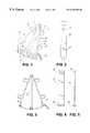
- FIG. 1is a phantom perspective of a first embodiment of the invention
- FIG. 2is a side view of the embodiment of FIG. 1,
- FIG. 3is a view of embodiment of FIG. 1 with the top removed to show the diaphragm vane
- FIGS. 4 and 5are side and top views of the vane
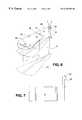
- FIG. 6is a phantom perspective of a second embodiment of the invention.
- FIG. 7is a side view of the vane of FIG. 6, and
- FIG. 8is a side view of the second embodiment.
- FIG. 1With reference to FIG. 1 there is shown a first embodiment of the invention, including a case 13 , a vane 9 and valves 1 , 2 , 3 , 4 .
- a plurality of electromagnets 11are energized by a power supply (not shown),via a cable 12 and attract the magnetic end 10 of vane 9 to successive positions along the arc of the casing 13 under control of the power supply.
- the sequence of energizing the magnets 11is normally from one end of the array to the other, the rate being determined by the pulse rate to be provided to the patient.
- the volume of each stroke of the mechanical heartis determined by the distance the vane travels along the arc.
- Ports 5 , 6 , 7 & 8are connected to the arteries and veins normally, with blood from the one side of the pump being circulated to the pulmonary system, and blood from the other side of the pump being circulated to the aorta, and to the vena cava whence it is returned to the first side of the pump.
- port 5is connected to the Superior Vena Cava, and Inferior Vena Cava, drawing blood from both when the vane 9 is moving away from the port 5 .
- Port 6is supplying blood to the Pulmonary Artery, which supplies blood to the lungs.
- Port 7is receiving blood from the Pulmonary Vein, and port 8 is connected to the Aorta, taking oxygenated blood to all parts of the body.
- FIGS. 4 and 5are respectively a side view and top view of the vane 9 .
- One end of the vanehas bearing means 14 fitted for rotation in depressions in the top and bottom surfaces of the case 13 .
- Magnet member 10 on the free end of the vane 9is moved in response to the energization of the array of magnets 11 , by the external power supply.
- the speed of motion of the vane 9is regulated by well known current control means in the power supply.
- the chambers of each side of the vanecan be made of a size to accommodate the actual cardiac output of the patient. Once the cardiac output has been determined the artificial heart may then be made to order. Stops 15 in each corner of the case 13 prevent the vane from crushing blood cells against the sides of the case.
- a mechanical heartFor a mechanical heart to be implantable in a human chest, it must meet specific requirements; it must not weigh more than about 300 grams, or 3 ⁇ 4 pound, it must fit into a chest cavity of approximately 5.5 ⁇ 3 ⁇ 3.5 inches, it must be stable within the chest, it must not crush blood cells, it must not cause blood clotting, it must pump the correct volume of blood at the correct pressure, and it must have a reliable power source.
- blood clottingshould be prevented, as there will always be a mixing and blood will be mixed and moved on either to the lungs or as oxygenated blood to serve the body.
- FIGS. 6 , 7 ,& 8A mechanically driven embodiment of the mechanical heart is shown in FIGS. 6 , 7 ,& 8 .
- a casing 13encloses a vane 9 which is attached to a shaft 20 which will extend through the skin of the patient in a housing 25 , and be connected to a reciprocating mechanical drive (not shown).
- a plate 21is fastened to the exterior of the case 13 , with pillars 22 , and is connected to the sternum of the patient by screws 26 to stabilize the position of the heart in the chest cavity of the patient.
- bloodis pumped by reciprocation of the vane 9 in the cavity 13 .
- the comers of the chamber 13will be rounded, as will the edges of the ports 5 , 6 , 7 & 8 , and some blood should be left in the chamber at the end of each stroke so there will always be a mixing action and blood will be moved on, and not remain in the chamber to clot.
- the top side of the sternum center sectionis only slightly convex, and the plate 20 could extend over the sides of the sternum onto the cartilage that joins the ribs to the sternum.
- the screws 26 in the sternummake a rigid connection to the unit 13 .
- the hole in the chest in the skinwill allow the shaft 20 to protrude about 1 ⁇ 2 inch, above the skin.
- the holeis of course stabilized in one position by the plate 21 being anchored to the sternum.
- the skinwill heal round the housing 25 to maintain cleanliness.
- the casing 13 and the plate 21are solidly joined so that the casing 13 will move in the the chest with movement of the rib cage and the sternum. Coughing will move it around, so there must be a flexible section in the shaft connected to shaft 20 .
- a simple variable speed electric motor and controlcan easily be positioned on the body of the patient.
- the exact position of the stabilizing pillars 22will depend on the the lie of the person's heart. Each heart is tailor made to fit the position of the damaged heart it replaces. The cavity created by the removal of the damaged heart must be filled by the mechanical heart and its outer molded shell around the casing 13 . As the mechanical heart must pump about 1 ⁇ 3 of a cup of blood at a time using a single chamber, it will not be very big and will weigh about 300 grams. The volume or cardiac output, the weight and size of the damaged heart can be ascertained and the mechanical heart designed to fit perfectly. In installing the mechanical heart, a heart/lung machine would be attached to the large blood vessels in the leg of the patient. The custom made mechanical heart whether electromagnetically or mechanically driven, would be put in place and set to operate with a heart lung machine still in place, until the mechanical heart takes over the circulation of blood.
Landscapes
- Health & Medical Sciences (AREA)
- Engineering & Computer Science (AREA)
- Heart & Thoracic Surgery (AREA)
- Cardiology (AREA)
- Hematology (AREA)
- Veterinary Medicine (AREA)
- Anesthesiology (AREA)
- Biomedical Technology (AREA)
- Mechanical Engineering (AREA)
- Life Sciences & Earth Sciences (AREA)
- Animal Behavior & Ethology (AREA)
- General Health & Medical Sciences (AREA)
- Public Health (AREA)
- Medical Informatics (AREA)
- Physics & Mathematics (AREA)
- Electromagnetism (AREA)
- External Artificial Organs (AREA)
- Prostheses (AREA)
Abstract
Description
The present invention relates to a total artificial mechanical heart for use in replacement of a human heart. In particular, the invention relates to such a device which has a single pumping chamber.
Numerous efforts have been made to replace a defective human heart with a mechanical device which replicates the pumping action of a normal human heart. Canadian published patent applications 2,105,908 and 2,105,935 to Mussivand et al, filed Sep. 10, 1993 both relate to hydraulically actuated mechanical pumps for duplicating blood pumping action of the human heart. A right ventricular assist device is shown in Canadian patent 1,234,953 which utilizes an elliptical chamber with a flexible diaphragm separating a sac for connection to the patient's blood system and a pressurizing chamber for augmenting the flow of blood from the sac.
U.S. Pat. No. 3,734,648 relates to a mechanical heart which injects a driving fluid into one side of a diaphragm dividing a chamber to cause the evacuation of blood from the opposite side of the chamber. The system includes a piston pump and an accumulator for the driving fluid. U.S. Pat. No. 5,578,077 of Nov. 26, 1996 teaches the use of a scroll type pump modified for medical applications. U.S. Pat. No. 5,549,667 teaches an external mechanical heart having blood contacting parts made of Zirconium and alloys thereof. U.S. Pat. No. 4,547,911 of Oct. 22, 1995 relates to an implantable heart pump which runs at a harmonic multiple of a normal heart beat frequency, thereby reducing the pump chamber volume.
Thus many inventors have attempted to duplicate the pumping action of the human heart in an implantable mechanical heart.
The present invention provides a single chamber mechanical heart which duplicates the function of a human heart with minimum moving mechanical parts, thus providing a simple reliable mechanism suitable for implantation in the chest of a patient in the space formerly occupied by a human heart. In one embodiment, the heart pumping action is powered by an electromagnetically operated diaphragm vane, with electrical connections to an external power source, which controls the pulse rate as well as the volume of blood pumped. In a second embodiment the pump is powered by a mechanical shaft extending through the skin of the patient. This shaft is rotated in an oscillatory fashion causing motion of the diaphragm vane to pump the blood. In this second embodiment, the pulse rate as well as the blood pressure are controlled by external drive mechanisms controlled by sensors connected to the patient.
In the accompanying drawings,
FIG. 1 is a phantom perspective of a first embodiment of the invention,
FIG. 2 is a side view of the embodiment of FIG. 1,
FIG. 3 is a view of embodiment of FIG. 1 with the top removed to show the diaphragm vane,
FIGS. 4 and 5 are side and top views of the vane,
FIG. 6 is a phantom perspective of a second embodiment of the invention,
FIG. 7 is a side view of the vane of FIG. 6, and
FIG. 8 is a side view of the second embodiment.
With reference to FIG. 1 there is shown a first embodiment of the invention, including acase 13, avane 9 andvalves electromagnets 11 are energized by a power supply (not shown),via acable 12 and attract themagnetic end 10 ofvane 9 to successive positions along the arc of thecasing 13 under control of the power supply. The sequence of energizing themagnets 11 is normally from one end of the array to the other, the rate being determined by the pulse rate to be provided to the patient. The volume of each stroke of the mechanical heart is determined by the distance the vane travels along the arc.Ports
By using a single vane to pump both sides of the artificial heart, a simple efficient mechanism is obtained which can effectively replace the human heart.
Specifically,port 5 is connected to the Superior Vena Cava, and Inferior Vena Cava, drawing blood from both when thevane 9 is moving away from theport 5.Port 6 is supplying blood to the Pulmonary Artery, which supplies blood to the lungs.Port 7 is receiving blood from the Pulmonary Vein, andport 8 is connected to the Aorta, taking oxygenated blood to all parts of the body.
FIGS. 4 and 5 are respectively a side view and top view of thevane 9. One end of the vane has bearing means14 fitted for rotation in depressions in the top and bottom surfaces of thecase 13.Magnet member 10 on the free end of thevane 9 is moved in response to the energization of the array ofmagnets 11, by the external power supply. The speed of motion of thevane 9 is regulated by well known current control means in the power supply.
The chambers of each side of the vane can be made of a size to accommodate the actual cardiac output of the patient. Once the cardiac output has been determined the artificial heart may then be made to order. Stops15 in each corner of thecase 13 prevent the vane from crushing blood cells against the sides of the case.
For a mechanical heart to be implantable in a human chest, it must meet specific requirements; it must not weigh more than about 300 grams, or ¾ pound, it must fit into a chest cavity of approximately 5.5×3×3.5 inches, it must be stable within the chest, it must not crush blood cells, it must not cause blood clotting, it must pump the correct volume of blood at the correct pressure, and it must have a reliable power source. By having a residual amount of blood in the chamber at all times, blood clotting should be prevented, as there will always be a mixing and blood will be mixed and moved on either to the lungs or as oxygenated blood to serve the body.
A mechanically driven embodiment of the mechanical heart is shown in FIGS.6,7,&8. As before, acasing 13 encloses avane 9 which is attached to ashaft 20 which will extend through the skin of the patient in ahousing 25, and be connected to a reciprocating mechanical drive (not shown). Aplate 21 is fastened to the exterior of thecase 13, withpillars 22, and is connected to the sternum of the patient byscrews 26 to stabilize the position of the heart in the chest cavity of the patient. As before blood is pumped by reciprocation of thevane 9 in thecavity 13. Preferably the comers of thechamber 13 will be rounded, as will the edges of theports
Stabilizing the unit to the sternum will not be difficult, since the distance between the pumping unit and the under side of the sternum is small. The top side of the sternum center section is only slightly convex, and theplate 20 could extend over the sides of the sternum onto the cartilage that joins the ribs to the sternum. The screws26 in the sternum make a rigid connection to theunit 13. The hole in the chest in the skin will allow theshaft 20 to protrude about ½ inch, above the skin. The hole is of course stabilized in one position by theplate 21 being anchored to the sternum. The skin will heal round thehousing 25 to maintain cleanliness.
Thecasing 13 and theplate 21 are solidly joined so that thecasing 13 will move in the the chest with movement of the rib cage and the sternum. Coughing will move it around, so there must be a flexible section in the shaft connected toshaft 20. A simple variable speed electric motor and control can easily be positioned on the body of the patient.
The exact position of the stabilizingpillars 22 will depend on the the lie of the person's heart. Each heart is tailor made to fit the position of the damaged heart it replaces. The cavity created by the removal of the damaged heart must be filled by the mechanical heart and its outer molded shell around thecasing 13. As the mechanical heart must pump about ⅓ of a cup of blood at a time using a single chamber, it will not be very big and will weigh about 300 grams. The volume or cardiac output, the weight and size of the damaged heart can be ascertained and the mechanical heart designed to fit perfectly. In installing the mechanical heart, a heart/lung machine would be attached to the large blood vessels in the leg of the patient. The custom made mechanical heart whether electromagnetically or mechanically driven, would be put in place and set to operate with a heart lung machine still in place, until the mechanical heart takes over the circulation of blood.
Claims (3)
1. A single chamber mechanical heart, having a casing in the shape of a circular sector of a cylinder, with upper and lower faces, an apex, and a curved circumferential wall opposite said apex and straight side walls joined at said apex a movable vane having a first end journaled in said apex, said vane extending substantially between said upper and lower faces, and a second end adjacent said curved circumferential wall an inlet port and an outlet port in each side wall of said chamber, and magnetoeletric drive means comprising said second end of said vane having a magnetically susceptible portion, and a plurality of circumferential surface and adapted to be energized by an electric current passing through one or more of said magnets for causing reciprocating rotation of said vane about said journal, said vane dividing said chamber into two segments of variable size as said vane moves toward and away from each side wall of said chamber, whereby blood is pumped into and out of each of said segments through said inlet and outlet ports by reciprocal motion of said vane.
2. A single chamber mechanical heart, having a casing in the shape of a circular sector of a cylinder, with upper and lower faces, an apex, and a curved circumferential wall opposite said apex and straight side walls joined at said apex, a movable vane having a first and journaled in said apex, said vane extending substantially between said upper and lower faces, and a second end adjacent said curved circumferential wall, an inlet port and an outlet port in each side wall of said chamber, and means for causing reciprocating rotation of said vane about said journal, said vane dividing said chamber into two segments of variable size as said vane moves toward and away from each side wall of said chamber, whereby blood is pumped into and out of each of said segments through said inlet and outlet ports by reciprocal motion of said vane and further comprising a shaft connected to said first end of said vane for reciprocal rotary motion, said shaft being contained within a housing for extending through the skin of a patient and adapted to be driven by an external motor to cause reciprocation of said vane.
3. A mechanical heart as claimed in claim2, and having means for attaching said casing to the sternum of a patient.
Priority Applications (2)
| Application Number | Priority Date | Filing Date | Title |
|---|---|---|---|
| US09/347,298US6197055B1 (en) | 1999-07-06 | 1999-07-06 | Single chamber mechanical heart |
| CA002313663ACA2313663C (en) | 1999-07-06 | 2000-07-06 | Single chamber mechanical heart |
Applications Claiming Priority (1)
| Application Number | Priority Date | Filing Date | Title |
|---|---|---|---|
| US09/347,298US6197055B1 (en) | 1999-07-06 | 1999-07-06 | Single chamber mechanical heart |
Publications (1)
| Publication Number | Publication Date |
|---|---|
| US6197055B1true US6197055B1 (en) | 2001-03-06 |
Family
ID=23363144
Family Applications (1)
| Application Number | Title | Priority Date | Filing Date |
|---|---|---|---|
| US09/347,298Expired - Fee RelatedUS6197055B1 (en) | 1999-07-06 | 1999-07-06 | Single chamber mechanical heart |
Country Status (2)
| Country | Link |
|---|---|
| US (1) | US6197055B1 (en) |
| CA (1) | CA2313663C (en) |
Cited By (39)
| Publication number | Priority date | Publication date | Assignee | Title |
|---|---|---|---|---|
| US6576010B2 (en)* | 2000-07-20 | 2003-06-10 | Izaak A. Ulert | Circular artificial heart |
| US20070015959A1 (en)* | 2000-02-14 | 2007-01-18 | Obtech Medical Ag | Male impotence prosthesis apparatus with wireless energy supply |
| US20080275296A1 (en)* | 2000-02-10 | 2008-11-06 | Obtech Medical Ag | Mechanical impotence treatment apparatus |
| WO2010042006A1 (en)* | 2008-10-10 | 2010-04-15 | Milux Holding S.A. | Heart help method |
| WO2010042009A1 (en)* | 2008-10-10 | 2010-04-15 | Milux Holding Sa | Heart help device, system, and method |
| WO2010042017A1 (en)* | 2008-10-10 | 2010-04-15 | Milux Holding Sa | Heart help device, system, and method |
| US20100145139A1 (en)* | 2000-02-10 | 2010-06-10 | Obtech Medical Ag | Controlled urinary incontinence treatment |
| US20100145138A1 (en)* | 2000-02-10 | 2010-06-10 | Obtech Medical Ag | Urinary incontinence treatment with wireless energy supply |
| US20100312164A1 (en)* | 2008-01-28 | 2010-12-09 | Peter Forsell | Implantable drainage device |
| US20100331616A1 (en)* | 2008-10-10 | 2010-12-30 | Peter Forsell | Method and instrument for treating obesity |
| US20110015473A1 (en)* | 2009-07-17 | 2011-01-20 | Teslux Holdings S.A. | Vaginal operation method for the treatment of urinary incontinence in women |
| US20110040143A1 (en)* | 2000-02-11 | 2011-02-17 | Obtech Medical Ag | Impotence treatment apparatus with energy transforming means |
| US20110196486A1 (en)* | 2008-10-10 | 2011-08-11 | Milux Holdings SA | Heart help device, system, and method |
| US20110196192A1 (en)* | 2008-10-10 | 2011-08-11 | Milux Holding S.A. | Heart help device, system, and method |
| US20110202041A1 (en)* | 2008-10-10 | 2011-08-18 | Milux Holding Sa | Fastening means for implantable medical control assembly |
| US8096938B2 (en) | 1999-08-12 | 2012-01-17 | Obtech Medical Ag | Controlled anal incontinence disease treatment |
| US8126558B2 (en) | 2000-02-14 | 2012-02-28 | Obtech Medical Ag | Controlled penile prosthesis |
| US8313423B2 (en) | 2000-02-14 | 2012-11-20 | Peter Forsell | Hydraulic anal incontinence treatment |
| US8545384B2 (en) | 1999-08-12 | 2013-10-01 | Obtech Medical Ag | Anal incontinence disease treatment with controlled wireless energy supply |
| US8600510B2 (en) | 2008-10-10 | 2013-12-03 | Milux Holding Sa | Apparatus, system and operation method for the treatment of female sexual dysfunction |
| US8734318B2 (en) | 2000-02-11 | 2014-05-27 | Obtech Medical Ag | Mechanical anal incontinence |
| US8764627B2 (en) | 2000-02-14 | 2014-07-01 | Obtech Medical Ag | Penile prosthesis |
| US8795150B2 (en) | 2008-10-10 | 2014-08-05 | Milux Holding S.A. | Heart help device, system, and method |
| US8874215B2 (en) | 2008-10-10 | 2014-10-28 | Peter Forsell | System, an apparatus, and a method for treating a sexual dysfunctional female patient |
| US9949812B2 (en) | 2009-07-17 | 2018-04-24 | Peter Forsell | Vaginal operation method for the treatment of anal incontinence in women |
| US10219898B2 (en) | 2008-10-10 | 2019-03-05 | Peter Forsell | Artificial valve |
| US10722631B2 (en) | 2018-02-01 | 2020-07-28 | Shifamed Holdings, Llc | Intravascular blood pumps and methods of use and manufacture |
| US11185677B2 (en) | 2017-06-07 | 2021-11-30 | Shifamed Holdings, Llc | Intravascular fluid movement devices, systems, and methods of use |
| US20220370785A1 (en)* | 2019-09-19 | 2022-11-24 | Triphasic Cardiac Pump Pty Ltd | Pump for mimicking physiological blood flow in a patient |
| US11511103B2 (en) | 2017-11-13 | 2022-11-29 | Shifamed Holdings, Llc | Intravascular fluid movement devices, systems, and methods of use |
| US11654275B2 (en) | 2019-07-22 | 2023-05-23 | Shifamed Holdings, Llc | Intravascular blood pumps with struts and methods of use and manufacture |
| US11724089B2 (en) | 2019-09-25 | 2023-08-15 | Shifamed Holdings, Llc | Intravascular blood pump systems and methods of use and control thereof |
| US11964145B2 (en) | 2019-07-12 | 2024-04-23 | Shifamed Holdings, Llc | Intravascular blood pumps and methods of manufacture and use |
| US12102815B2 (en) | 2019-09-25 | 2024-10-01 | Shifamed Holdings, Llc | Catheter blood pumps and collapsible pump housings |
| US12121713B2 (en) | 2019-09-25 | 2024-10-22 | Shifamed Holdings, Llc | Catheter blood pumps and collapsible blood conduits |
| US12161857B2 (en) | 2018-07-31 | 2024-12-10 | Shifamed Holdings, Llc | Intravascular blood pumps and methods of use |
| US12220570B2 (en) | 2018-10-05 | 2025-02-11 | Shifamed Holdings, Llc | Intravascular blood pumps and methods of use |
| US12409310B2 (en) | 2019-12-11 | 2025-09-09 | Shifamed Holdings, Llc | Descending aorta and vena cava blood pumps |
| US12440664B2 (en) | 2008-10-10 | 2025-10-14 | Peter Forsell | Method of fixating a heart help device |
Citations (11)
| Publication number | Priority date | Publication date | Assignee | Title |
|---|---|---|---|---|
| US3734648A (en) | 1969-09-24 | 1973-05-22 | J Nielson | Mechanical heart system |
| US4058857A (en)* | 1976-02-12 | 1977-11-22 | Runge Thomas M | Cardiac replacement pumping devices |
| US4221548A (en)* | 1978-03-20 | 1980-09-09 | Child Frank W | Dual action solenoid pump |
| US4547911A (en) | 1983-12-02 | 1985-10-22 | Strimling Walter E | Implantable heart pump |
| US4650485A (en)* | 1983-12-30 | 1987-03-17 | Berardino Della Sala | Total artificial heart |
| CA1234953A (en) | 1984-03-19 | 1988-04-12 | William Pierce | Right ventricular assist device |
| US4869656A (en)* | 1986-12-23 | 1989-09-26 | Berardino Della Sala | Ferromagnetic-fluid pump for pumping biological liquid |
| CA2105935A1 (en) | 1993-09-10 | 1995-03-11 | Tofy Mussivand | Electrohydraulic ventricular assist device |
| CA2105908A1 (en) | 1993-09-10 | 1995-03-11 | Tofy Mussivand | Electrohydraulic assist device |
| US5549667A (en) | 1989-07-25 | 1996-08-27 | Smith & Nephew Richards, Inc. | Mechanical heart with wear resistant coatings of reduced thrombogenicity |
| US5578077A (en) | 1988-10-17 | 1996-11-26 | Kassatly; Samuel A. | Mechanical heart, body fluid and drug infusion pump |
- 1999
- 1999-07-06USUS09/347,298patent/US6197055B1/ennot_activeExpired - Fee Related
- 2000
- 2000-07-06CACA002313663Apatent/CA2313663C/ennot_activeExpired - Fee Related
Patent Citations (11)
| Publication number | Priority date | Publication date | Assignee | Title |
|---|---|---|---|---|
| US3734648A (en) | 1969-09-24 | 1973-05-22 | J Nielson | Mechanical heart system |
| US4058857A (en)* | 1976-02-12 | 1977-11-22 | Runge Thomas M | Cardiac replacement pumping devices |
| US4221548A (en)* | 1978-03-20 | 1980-09-09 | Child Frank W | Dual action solenoid pump |
| US4547911A (en) | 1983-12-02 | 1985-10-22 | Strimling Walter E | Implantable heart pump |
| US4650485A (en)* | 1983-12-30 | 1987-03-17 | Berardino Della Sala | Total artificial heart |
| CA1234953A (en) | 1984-03-19 | 1988-04-12 | William Pierce | Right ventricular assist device |
| US4869656A (en)* | 1986-12-23 | 1989-09-26 | Berardino Della Sala | Ferromagnetic-fluid pump for pumping biological liquid |
| US5578077A (en) | 1988-10-17 | 1996-11-26 | Kassatly; Samuel A. | Mechanical heart, body fluid and drug infusion pump |
| US5549667A (en) | 1989-07-25 | 1996-08-27 | Smith & Nephew Richards, Inc. | Mechanical heart with wear resistant coatings of reduced thrombogenicity |
| CA2105935A1 (en) | 1993-09-10 | 1995-03-11 | Tofy Mussivand | Electrohydraulic ventricular assist device |
| CA2105908A1 (en) | 1993-09-10 | 1995-03-11 | Tofy Mussivand | Electrohydraulic assist device |
Cited By (78)
| Publication number | Priority date | Publication date | Assignee | Title |
|---|---|---|---|---|
| US8545384B2 (en) | 1999-08-12 | 2013-10-01 | Obtech Medical Ag | Anal incontinence disease treatment with controlled wireless energy supply |
| US8096938B2 (en) | 1999-08-12 | 2012-01-17 | Obtech Medical Ag | Controlled anal incontinence disease treatment |
| US20100145139A1 (en)* | 2000-02-10 | 2010-06-10 | Obtech Medical Ag | Controlled urinary incontinence treatment |
| US8096939B2 (en) | 2000-02-10 | 2012-01-17 | Obtech Medical Ag | Urinary incontinence treatment with wireless energy supply |
| US20080275296A1 (en)* | 2000-02-10 | 2008-11-06 | Obtech Medical Ag | Mechanical impotence treatment apparatus |
| US20090054725A1 (en)* | 2000-02-10 | 2009-02-26 | Obtech Medical Ag | Mechanical impotence treatment apparatus |
| US8287444B2 (en) | 2000-02-10 | 2012-10-16 | Obtech Medical Ag | Mechanical impotence treatment apparatus |
| US8556796B2 (en) | 2000-02-10 | 2013-10-15 | Obtech Medical Ag | Controlled urinary incontinence treatment |
| US8602966B2 (en) | 2000-02-10 | 2013-12-10 | Obtech Medical, AG | Mechanical impotence treatment apparatus |
| US20100145138A1 (en)* | 2000-02-10 | 2010-06-10 | Obtech Medical Ag | Urinary incontinence treatment with wireless energy supply |
| US20110040143A1 (en)* | 2000-02-11 | 2011-02-17 | Obtech Medical Ag | Impotence treatment apparatus with energy transforming means |
| US8734318B2 (en) | 2000-02-11 | 2014-05-27 | Obtech Medical Ag | Mechanical anal incontinence |
| US8290594B2 (en) | 2000-02-11 | 2012-10-16 | Obtech Medical Ag | Impotence treatment apparatus with energy transforming means |
| US8678997B2 (en) | 2000-02-14 | 2014-03-25 | Obtech Medical Ag | Male impotence prosthesis apparatus with wireless energy supply |
| US20070015959A1 (en)* | 2000-02-14 | 2007-01-18 | Obtech Medical Ag | Male impotence prosthesis apparatus with wireless energy supply |
| US8764627B2 (en) | 2000-02-14 | 2014-07-01 | Obtech Medical Ag | Penile prosthesis |
| US8126558B2 (en) | 2000-02-14 | 2012-02-28 | Obtech Medical Ag | Controlled penile prosthesis |
| US8313423B2 (en) | 2000-02-14 | 2012-11-20 | Peter Forsell | Hydraulic anal incontinence treatment |
| US6576010B2 (en)* | 2000-07-20 | 2003-06-10 | Izaak A. Ulert | Circular artificial heart |
| US8961448B2 (en) | 2008-01-28 | 2015-02-24 | Peter Forsell | Implantable drainage device |
| US20150157836A1 (en)* | 2008-01-28 | 2015-06-11 | Peter Mats Forsell | Implantable drainage device |
| US9694165B2 (en)* | 2008-01-28 | 2017-07-04 | Peter Mats Forsell | Implantable drainage device |
| US20100312164A1 (en)* | 2008-01-28 | 2010-12-09 | Peter Forsell | Implantable drainage device |
| US9060771B2 (en) | 2008-01-29 | 2015-06-23 | Peter Forsell | Method and instrument for treating obesity |
| US8636809B2 (en) | 2008-01-29 | 2014-01-28 | Milux Holding Sa | Device for treating obesity |
| US20100332000A1 (en)* | 2008-01-29 | 2010-12-30 | Peter Forsell | Device for treating obesity |
| US20110196486A1 (en)* | 2008-10-10 | 2011-08-11 | Milux Holdings SA | Heart help device, system, and method |
| US9370656B2 (en) | 2008-10-10 | 2016-06-21 | Peter Forsell | System, an apparatus, and a method for treating a sexual dysfunctional female patient |
| US20110202041A1 (en)* | 2008-10-10 | 2011-08-18 | Milux Holding Sa | Fastening means for implantable medical control assembly |
| US20110202131A1 (en)* | 2008-10-10 | 2011-08-18 | Milux Holding Sa | Heart help device, system, and method |
| US20110196192A1 (en)* | 2008-10-10 | 2011-08-11 | Milux Holding S.A. | Heart help device, system, and method |
| US20110196193A1 (en)* | 2008-10-10 | 2011-08-11 | Milux Holding Sa | Heart help device, system and method |
| US8469874B2 (en) | 2008-10-10 | 2013-06-25 | Milux Holding Sa | Heart help device, system, and method |
| US8475355B2 (en) | 2008-10-10 | 2013-07-02 | Milux Holding S.A. | Heart help device, system, and method |
| US8509894B2 (en) | 2008-10-10 | 2013-08-13 | Milux Holding Sa | Heart help device, system, and method |
| US20110196485A1 (en)* | 2008-10-10 | 2011-08-11 | Peter Forsell | Heart help device, system, and method |
| US12440664B2 (en) | 2008-10-10 | 2025-10-14 | Peter Forsell | Method of fixating a heart help device |
| US8600510B2 (en) | 2008-10-10 | 2013-12-03 | Milux Holding Sa | Apparatus, system and operation method for the treatment of female sexual dysfunction |
| US20100331616A1 (en)* | 2008-10-10 | 2010-12-30 | Peter Forsell | Method and instrument for treating obesity |
| WO2010042018A1 (en)* | 2008-10-10 | 2010-04-15 | Milux Holding S.A. | Heart help device, system and method |
| WO2010042019A1 (en)* | 2008-10-10 | 2010-04-15 | Milux Holding Sa | Heart help device, system, and method |
| US8696745B2 (en) | 2008-10-10 | 2014-04-15 | Kirk Promotion Ltd. | Heart help device, system, and method |
| WO2010042011A1 (en)* | 2008-10-10 | 2010-04-15 | Milux Holding Sa | Heart help device, system, and method |
| WO2010042012A1 (en)* | 2008-10-10 | 2010-04-15 | Milux Holding Sa | Heart help device, system, and method |
| US8795150B2 (en) | 2008-10-10 | 2014-08-05 | Milux Holding S.A. | Heart help device, system, and method |
| US8874215B2 (en) | 2008-10-10 | 2014-10-28 | Peter Forsell | System, an apparatus, and a method for treating a sexual dysfunctional female patient |
| WO2010042017A1 (en)* | 2008-10-10 | 2010-04-15 | Milux Holding Sa | Heart help device, system, and method |
| US9005104B2 (en) | 2008-10-10 | 2015-04-14 | Peter Forsell | Heart help device, system, and method |
| WO2010042009A1 (en)* | 2008-10-10 | 2010-04-15 | Milux Holding Sa | Heart help device, system, and method |
| WO2010042014A1 (en)* | 2008-10-10 | 2010-04-15 | Milux Holding Sa | Heart help device, system, and method |
| US9072907B2 (en) | 2008-10-10 | 2015-07-07 | Peter Forsell | Heart help device, system, and method |
| US20110224787A1 (en)* | 2008-10-10 | 2011-09-15 | Milux Holding Sa | Heart help device, system, and method |
| US9526649B2 (en) | 2008-10-10 | 2016-12-27 | Peter Forsell | Method and instrument for treating obesity |
| WO2010042006A1 (en)* | 2008-10-10 | 2010-04-15 | Milux Holding S.A. | Heart help method |
| US12409327B2 (en)* | 2008-10-10 | 2025-09-09 | Peter Forsell | Heart help device, system, and method |
| US10219898B2 (en) | 2008-10-10 | 2019-03-05 | Peter Forsell | Artificial valve |
| US10583234B2 (en) | 2008-10-10 | 2020-03-10 | Peter Forsell | Heart help device, system and method |
| US10668196B2 (en) | 2008-10-10 | 2020-06-02 | Peter Forsell | Heart assisting device |
| US20230405333A1 (en)* | 2008-10-10 | 2023-12-21 | Peter Forsell | Heart help device, system, and method |
| US11123171B2 (en) | 2008-10-10 | 2021-09-21 | Peter Forsell | Fastening means for implantable medical control assembly |
| US20110015473A1 (en)* | 2009-07-17 | 2011-01-20 | Teslux Holdings S.A. | Vaginal operation method for the treatment of urinary incontinence in women |
| US9949812B2 (en) | 2009-07-17 | 2018-04-24 | Peter Forsell | Vaginal operation method for the treatment of anal incontinence in women |
| US10952836B2 (en) | 2009-07-17 | 2021-03-23 | Peter Forsell | Vaginal operation method for the treatment of urinary incontinence in women |
| US11717670B2 (en) | 2017-06-07 | 2023-08-08 | Shifamed Holdings, LLP | Intravascular fluid movement devices, systems, and methods of use |
| US11185677B2 (en) | 2017-06-07 | 2021-11-30 | Shifamed Holdings, Llc | Intravascular fluid movement devices, systems, and methods of use |
| US11511103B2 (en) | 2017-11-13 | 2022-11-29 | Shifamed Holdings, Llc | Intravascular fluid movement devices, systems, and methods of use |
| US10722631B2 (en) | 2018-02-01 | 2020-07-28 | Shifamed Holdings, Llc | Intravascular blood pumps and methods of use and manufacture |
| US12076545B2 (en) | 2018-02-01 | 2024-09-03 | Shifamed Holdings, Llc | Intravascular blood pumps and methods of use and manufacture |
| US11229784B2 (en) | 2018-02-01 | 2022-01-25 | Shifamed Holdings, Llc | Intravascular blood pumps and methods of use and manufacture |
| US12161857B2 (en) | 2018-07-31 | 2024-12-10 | Shifamed Holdings, Llc | Intravascular blood pumps and methods of use |
| US12220570B2 (en) | 2018-10-05 | 2025-02-11 | Shifamed Holdings, Llc | Intravascular blood pumps and methods of use |
| US11964145B2 (en) | 2019-07-12 | 2024-04-23 | Shifamed Holdings, Llc | Intravascular blood pumps and methods of manufacture and use |
| US11654275B2 (en) | 2019-07-22 | 2023-05-23 | Shifamed Holdings, Llc | Intravascular blood pumps with struts and methods of use and manufacture |
| US20220370785A1 (en)* | 2019-09-19 | 2022-11-24 | Triphasic Cardiac Pump Pty Ltd | Pump for mimicking physiological blood flow in a patient |
| US11724089B2 (en) | 2019-09-25 | 2023-08-15 | Shifamed Holdings, Llc | Intravascular blood pump systems and methods of use and control thereof |
| US12102815B2 (en) | 2019-09-25 | 2024-10-01 | Shifamed Holdings, Llc | Catheter blood pumps and collapsible pump housings |
| US12121713B2 (en) | 2019-09-25 | 2024-10-22 | Shifamed Holdings, Llc | Catheter blood pumps and collapsible blood conduits |
| US12409310B2 (en) | 2019-12-11 | 2025-09-09 | Shifamed Holdings, Llc | Descending aorta and vena cava blood pumps |
Also Published As
| Publication number | Publication date |
|---|---|
| CA2313663C (en) | 2001-12-11 |
| CA2313663A1 (en) | 2001-01-06 |
Similar Documents
| Publication | Publication Date | Title |
|---|---|---|
| US6197055B1 (en) | Single chamber mechanical heart | |
| US11623077B2 (en) | Implantable pump system having a rectangular membrane | |
| US11298522B2 (en) | Implantable pump system having an undulating membrane | |
| CA2916350C (en) | Artificial ventricles | |
| US4381567A (en) | Hydraulically actuated total cardiac prosthesis with reversible pump and three-way ventricular valving | |
| US7588530B2 (en) | Devices, systems and methods for assisting blood flow | |
| US4397049A (en) | Hydraulically actuated cardiac prosthesis with three-way ventricular valving | |
| US5066300A (en) | Twin replacement heart | |
| US4369530A (en) | Hydraulically actuated cardiac prosthesis and method of actuation | |
| Goodman et al. | Left ventricular assist devices: A historical perspective at the intersection of medicine and engineering | |
| US4389737A (en) | Hydraulically actuated cardiac prosthesis with three-way ventricular valving | |
| EP0079373B1 (en) | Hydraulically actuated cardiac prosthesis | |
| US4376312A (en) | Hydraulically actuated cardiac prosthesis | |
| EP0661961B1 (en) | Linear motion, muscle-actuated cardiac assist device | |
| EP0272445B1 (en) | A ferromagnetic-fluid pump for pumping biological liquid | |
| US20250205473A1 (en) | Blood pumps having an encapsulated actuator | |
| US8372145B2 (en) | Implantable artificial ventricle having low energy requirement | |
| Weiss et al. | Permanent circulatory support systems at the Pennsylvania State University | |
| RU201911U1 (en) | Blood flow control device for extracorporeal circulatory support systems | |
| US20180064864A1 (en) | Artificial Ventricles | |
| Pierce et al. | An electric artificial heart for clinical use | |
| RU2732084C1 (en) | Artificial heart | |
| RU202952U1 (en) | Blood flow control device for implantable circulatory support systems | |
| Takatani | Cardiac prosthesis as an advanced surgical therapy for end-stage cardiac patients: current status and future perspectives | |
| Mitsui et al. | An electrically-driven rotary blood pump based on the Wankel engine |
Legal Events
| Date | Code | Title | Description |
|---|---|---|---|
| CC | Certificate of correction | ||
| REMI | Maintenance fee reminder mailed | ||
| LAPS | Lapse for failure to pay maintenance fees | ||
| STCH | Information on status: patent discontinuation | Free format text:PATENT EXPIRED DUE TO NONPAYMENT OF MAINTENANCE FEES UNDER 37 CFR 1.362 | |
| FP | Lapsed due to failure to pay maintenance fee | Effective date:20050306 |