US6196820B1 - Device for filtering plastics in injection molding machines - Google Patents
Device for filtering plastics in injection molding machinesDownload PDFInfo
- Publication number
- US6196820B1 US6196820B1US09/267,479US26747999AUS6196820B1US 6196820 B1US6196820 B1US 6196820B1US 26747999 AUS26747999 AUS 26747999AUS 6196820 B1US6196820 B1US 6196820B1
- Authority
- US
- United States
- Prior art keywords
- filter element
- slide
- receptacle
- piston
- connection line
- Prior art date
- Legal status (The legal status is an assumption and is not a legal conclusion. Google has not performed a legal analysis and makes no representation as to the accuracy of the status listed.)
- Expired - Fee Related
Links
- 239000004033plasticSubstances0.000titleclaimsabstractdescription20
- 229920003023plasticPolymers0.000titleclaimsabstractdescription20
- 238000001746injection mouldingMethods0.000titleclaimsabstractdescription19
- 238000001914filtrationMethods0.000titleclaimsabstractdescription5
- 239000000126substanceSubstances0.000claimsabstractdescription26
- 230000000903blocking effectEffects0.000claimsabstractdescription20
- 238000002347injectionMethods0.000claimsabstractdescription7
- 239000007924injectionSubstances0.000claimsabstractdescription7
- 238000005266castingMethods0.000claimsabstract11
- 238000007789sealingMethods0.000claimsdescription18
- 239000000463materialSubstances0.000claimsdescription7
- 238000010438heat treatmentMethods0.000claimsdescription4
- RTAQQCXQSZGOHL-UHFFFAOYSA-NTitaniumChemical compound[Ti]RTAQQCXQSZGOHL-UHFFFAOYSA-N0.000claims1
- 229910052719titaniumInorganic materials0.000claims1
- 239000010936titaniumSubstances0.000claims1
- 238000000034methodMethods0.000abstractdescription3
- 238000003780insertionMethods0.000abstractdescription2
- 230000037431insertionEffects0.000abstractdescription2
- 238000006073displacement reactionMethods0.000abstract2
- 239000002184metalSubstances0.000description4
- 239000012778molding materialSubstances0.000description4
- 238000011010flushing procedureMethods0.000description2
- 238000012545processingMethods0.000description2
- 229910000831SteelInorganic materials0.000description1
- 230000002411adverseEffects0.000description1
- 238000004891communicationMethods0.000description1
- 238000010276constructionMethods0.000description1
- 230000007547defectEffects0.000description1
- 238000010586diagramMethods0.000description1
- 239000013013elastic materialSubstances0.000description1
- 238000001125extrusionMethods0.000description1
- 239000011796hollow space materialSubstances0.000description1
- 238000004519manufacturing processMethods0.000description1
- 239000000155meltSubstances0.000description1
- 238000003825pressingMethods0.000description1
- 238000012216screeningMethods0.000description1
- 239000007921spraySubstances0.000description1
- 239000010959steelSubstances0.000description1
- 230000001502supplementing effectEffects0.000description1
Images

Classifications
- B—PERFORMING OPERATIONS; TRANSPORTING
- B29—WORKING OF PLASTICS; WORKING OF SUBSTANCES IN A PLASTIC STATE IN GENERAL
- B29C—SHAPING OR JOINING OF PLASTICS; SHAPING OF MATERIAL IN A PLASTIC STATE, NOT OTHERWISE PROVIDED FOR; AFTER-TREATMENT OF THE SHAPED PRODUCTS, e.g. REPAIRING
- B29C45/00—Injection moulding, i.e. forcing the required volume of moulding material through a nozzle into a closed mould; Apparatus therefor
- B29C45/17—Component parts, details or accessories; Auxiliary operations
- B29C45/20—Injection nozzles
- B29C45/24—Cleaning equipment
- B—PERFORMING OPERATIONS; TRANSPORTING
- B29—WORKING OF PLASTICS; WORKING OF SUBSTANCES IN A PLASTIC STATE IN GENERAL
- B29C—SHAPING OR JOINING OF PLASTICS; SHAPING OF MATERIAL IN A PLASTIC STATE, NOT OTHERWISE PROVIDED FOR; AFTER-TREATMENT OF THE SHAPED PRODUCTS, e.g. REPAIRING
- B29C45/00—Injection moulding, i.e. forcing the required volume of moulding material through a nozzle into a closed mould; Apparatus therefor
- B29C45/17—Component parts, details or accessories; Auxiliary operations
- B29C45/1753—Cleaning or purging, e.g. of the injection unit
- B—PERFORMING OPERATIONS; TRANSPORTING
- B29—WORKING OF PLASTICS; WORKING OF SUBSTANCES IN A PLASTIC STATE IN GENERAL
- B29C—SHAPING OR JOINING OF PLASTICS; SHAPING OF MATERIAL IN A PLASTIC STATE, NOT OTHERWISE PROVIDED FOR; AFTER-TREATMENT OF THE SHAPED PRODUCTS, e.g. REPAIRING
- B29C45/00—Injection moulding, i.e. forcing the required volume of moulding material through a nozzle into a closed mould; Apparatus therefor
- B29C45/17—Component parts, details or accessories; Auxiliary operations
- B29C45/46—Means for plasticising or homogenising the moulding material or forcing it into the mould
- B29C45/57—Exerting after-pressure on the moulding material
Definitions
- the present inventionis directed to a process and a corresponding device for filtering plastics in an injection molding machine in which a holding device receiving a filter element is arranged between a plasticizing unit and a mold cavity.
- Kunststoffe [Plastics] 87(1997), pages 154-159, discloses a screen system (page 156) in which the screening locations are arranged in a rectangular slide (cassette) or a round bolt. Changing is initiated manually or automatically via a hydraulic drive when a defined pressure limit is reached by displacing the screen surface carrier.
- German reference DE 44 19 284 C1discloses a filter device for plastic melts in which screen inserts are arranged in a power-operated displaceable slide. Seals are arranged at both sides of the slide, wherein at least one of the seals has a sealing body made of metal which encloses a hollow space that is filled with a substance whose thermal expansion coefficient exceeds that of the material of the sealing body.
- its sealing bodywhich is made of metal, for example, high-grade steel, is relaxed in practice.
- the sealing bodyincluding the material with which it is filled, expands thermally so that the end face of the seal lies firmly against the slide in a sealing manner during operation after the thermal expansion or deformation.
- a disadvantage in this type of sealis its dependence on the pressure and on the temperature of the processed plastic substance such that at low pressure and low temperature leaks occur and at high pressure and high temperature undesirably high area pressing occurs in the support surfaces.
- a preheated filter elementis used when changing filters, wherein the preheated filter element is acted upon by the plastic substance which is kept away from the mold cavity until the cast substance is determined as suitable and is accordingly supplied without defects for processing.
- a 3-way cockwith the following operating positions:
- a blocking memberprevents any influencing of the filter and of the screw out of the tool or distributor system, e.g., hot channel in the case of multiple components, and the like.
- the flushing positionsprays out air volume and old material after changing the filter units, particularly when starting the injection molding machine and when changing filters.
- a preheating deviceis provided so as to preheat fresh filter elements.
- a filter holderis provided as a slide in which the active filter is mounted. The slide is displaceable and movable into a position in which its receptacle for the filter element corresponds with a piston-shaped displacing unit by means of which a spent filter element is ejected and a fresh filter element simultaneously inserted.
- the displacing unithas, in the region of the filter holder, the preheating device by means of which the filter elements are preheated to operating temperature.
- the preheatingadvantageously prevents the plastic substance from solidifying in the fresh filter at a next injection stroke, which would cause an interruption in production.
- the slideis arranged as a carrier plate by which the spent filter is pulled out of the filter holder from the top.
- the preheated filter elementis slid into the carrier plate by means of the piston of the displacing unit. In so doing, the spent filter element is ejected away from the displacing unit into a collection channel or gutter.
- the filter elementis also thermally influenced with respect to its operating position.
- a filter heateris provided in the slide in a region in which the filter element is received.
- the slide receiving the filter elementbe easily movable for changing, it is also desirable that the slide be held in a tightly closing manner during operation so as not to allow leakage.
- a sealing ringwhich comprises at least two parts is provided between the slide and the housing on a side of the slide directed toward the plasticizing unit.
- the sealing ringis either free of play or is pressed against the slide depending on substance pressure present in the plasticizing unit channel.
- one seal part of the sealing ringis roof-shaped, while another seal part has a triangular shape, wherein both seal parts contact one another along an inclined surface.
- Both seal partsare made exclusively of metal, wherein at least the roof-shaped sealing ring is preferably manufactured from a highly-elastic material. In a pressureless state, both sealing rings are sprung back and lean lightly against one another in a pretensioned manner.
- the diameterincreases with respect to the roof-shaped sealing ring.
- the roof-shaped seal partexpands radially outward the sloping surface which is inclined toward the triangular sealing ring moves the triangular sealing ring axially and presses it against the slide.
- the angle of the contacting inclined surfaces of the two seal partsis selected in such a way that these seal parts do not jam and they spring back into their initial position in the pressureless state.
- a metal with a low modulus of elasticityis used so as to promote the required deformation.
- the blocking member provided in the connection lineis a 3-way cock that can be connected with an accumulator.
- the injection molding substance that has been found to be of good qualityis additionally influenced with respect to its pressure and its quantity by this accumulator.
- the accumulatoris a piston-cylinder unit which is hydraulically or electrically driven.
- the piston-cylinder unithas a piston rod and which is thermally separated from the injection molding substance, so that the injection molding substance is not negatively influenced.
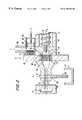
- FIG. 1shows a diagram of an injection molding unit incorporating the present invention
- FIG. 2shows a portion of the injection molding unit with a filter changing and blocking device
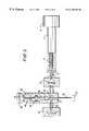
- FIG. 3shows the injection molding unit with a filter and accumulator.
- FIG. 1shows an injection molding unit with a plasticizing unit 11 having a housing 18 and a screw 12 driven in the housing 18 via a screw drive 13 .
- the housing 18has, at its outlet side, a channel 14 which communicates with a nozzle 15 via a connection line 35 , so that an injection molding material driven by the screw 12 is guidable through the nozzle 15 to a mold cavity 17 arranged in a tool 16 .
- a slide 61 having a receptacle 62 for a filter element 21is arranged in a region of the channel 14 so as to be movable perpendicular to a principal axis I of the plasticizing unit 11 .
- a filter heating device 72encloses the receptacle 62 for the purpose of heating the filter element 21 .
- the slide 61corresponds in a filter changing position with a piston-shaped displacing unit 66 having a piston-cylinder unit 64 and a secondary axis II arranged parallel to the principal axis I of the plasticizing unit 11 .
- a filter holder 63into which a fresh filter element 21 is insertable, is arranged in an outlet area of the displacing unit 66 .
- the center of the receptacle 62is displaced from the principal axis I of the plasticizing unit 11 to the secondary axis II of the displacing unit 66 .
- the fresh filter element 21is moved out of the filter holder 63 into the receptacle 62 of the slide 61 by movement of the piston-cylinder unit 64 which simultaneously ejects the spent filter element (not shown here) from the slide 61 .
- a preheating device 71is arranged at the filter holder 63 to bring the fresh filter element 21 to a desired operating temperature.
- the fresh filter elements 21are fed via a magazine 65 connected with the filter holder 63 .
- a positionable blocking member 31preferably a 3-way cock 33 , is arranged in the connection line 35 downstream of the slide 61 and the filter 21 .
- the channel 14In one position (through) of the blocking member 31 , the channel 14 , and, therefore, filtered injection molding material, is in communication with the mold cavity 17 ; in a second position (divert), the channel 14 is connected with an off-injection receptacle 37 via a branch 36 ; and in a third position (block) both the connection line 35 and the branch 36 are blocked.
- FIG. 2shows a portion of FIG. 1 in a region of the slide 61 and the blocking member 31 .
- the blocking member 31is constructed as a slide member with the positions: through, block and divert, as in the case of the 3-way cock 33 , above.
- a sealing ring 81is in contact with the slide 61 and the housing 18 .
- the sealing ring 81comprises two seal parts, namely a roof-shaped seal part 82 and a triangular seal part 83 which slideably contact one another over an entire surface.
- FIG. 3shows an injection molding unit in which an accumulator 41 communicates with the blocking member 31 for supplementing the branch 36 .
- the accumulator 41has an adjusting element 42 configured as a piston-cylinder unit 43 having a piston rod 44 connectable (not shown) to a hydraulic drive or an electric drive.
- a material 46is arranged in an area of the piston rod 44 so as to thermally separate the piston 45 from the drive, to prevent adversely influencing the temperature of the injection molding material.
Landscapes
- Engineering & Computer Science (AREA)
- Manufacturing & Machinery (AREA)
- Mechanical Engineering (AREA)
- Injection Moulding Of Plastics Or The Like (AREA)
- Moulds For Moulding Plastics Or The Like (AREA)
- Processing And Handling Of Plastics And Other Materials For Molding In General (AREA)
- Extrusion Moulding Of Plastics Or The Like (AREA)
- Blow-Moulding Or Thermoforming Of Plastics Or The Like (AREA)
Abstract
Description
Claims (14)
Applications Claiming Priority (2)
| Application Number | Priority Date | Filing Date | Title |
|---|---|---|---|
| DE19811273 | 1998-03-11 | ||
| DE19811273ADE19811273C2 (en) | 1998-03-11 | 1998-03-11 | Method and device for filtering plastics in injection molding machines |
Publications (1)
| Publication Number | Publication Date |
|---|---|
| US6196820B1true US6196820B1 (en) | 2001-03-06 |
Family
ID=7861008
Family Applications (1)
| Application Number | Title | Priority Date | Filing Date |
|---|---|---|---|
| US09/267,479Expired - Fee RelatedUS6196820B1 (en) | 1998-03-11 | 1999-03-11 | Device for filtering plastics in injection molding machines |
Country Status (4)
| Country | Link |
|---|---|
| US (1) | US6196820B1 (en) |
| EP (1) | EP0949054B1 (en) |
| AT (1) | ATE210544T1 (en) |
| DE (2) | DE19811273C2 (en) |
Cited By (9)
| Publication number | Priority date | Publication date | Assignee | Title |
|---|---|---|---|---|
| US20120074607A1 (en)* | 2009-06-19 | 2012-03-29 | Husky Injection Molding Systems Ltd. | In an injection unit having a filter, a method of controlling melt pressure in accordance with a target pressure range |
| US20120082753A1 (en)* | 2009-06-25 | 2012-04-05 | Husky Injection Molding Systems Ltd | injection molding system including a melt filter, the filter being located before first instance of melt accumulation |
| CN102666065A (en)* | 2009-11-25 | 2012-09-12 | 日精Asb机械株式会社 | Injection device and resin injection method |
| CN110587919A (en)* | 2019-09-19 | 2019-12-20 | 五邑大学 | Screen changer and its method |
| US10828815B2 (en) | 2014-12-15 | 2020-11-10 | Husky Injection Molding Systems Ltd. | Injection molding machine |
| US10933357B2 (en)* | 2016-10-17 | 2021-03-02 | Next Generation Analytics Gmbh | Filter system for viscous or highly viscous liquids, in particular plastic melts and method for filtering viscous or highly viscous liquids |
| US11260570B2 (en)* | 2018-05-07 | 2022-03-01 | PSI-Polymer Systems, Inc. | Filtration apparatuses and screen changer devices for polymer processing and related methods |
| US20240009889A1 (en)* | 2022-07-11 | 2024-01-11 | Engel Austria Gmbh | Plasticizing unit for a molding machine |
| CN117400483A (en)* | 2023-12-06 | 2024-01-16 | 太仓市天丝利塑化有限公司 | Double-cylinder type automobile injection molding accessory injection molding machine |
Families Citing this family (4)
| Publication number | Priority date | Publication date | Assignee | Title |
|---|---|---|---|---|
| US7393479B2 (en)* | 2004-10-15 | 2008-07-01 | Husky Injection Molding Systems Ltd. | Injection molding three-way shut off valve |
| AT516900A1 (en)* | 2015-03-09 | 2016-09-15 | Dr Collin Gmbh | Apparatus and method for testing materials |
| AT524784B1 (en)* | 2021-04-07 | 2022-09-15 | Engel Austria Gmbh | Plasticizing unit for a shaping machine and method for operating one |
| AT525547B1 (en)* | 2022-07-11 | 2023-05-15 | Engel Austria Gmbh | filter device |
Citations (5)
| Publication number | Priority date | Publication date | Assignee | Title |
|---|---|---|---|---|
| US3962092A (en)* | 1975-01-10 | 1976-06-08 | The Dow Chemical Company | Screen changer |
| US4167384A (en)* | 1977-11-28 | 1979-09-11 | The Japan Steel Works, Ltd. | Filter screen exchanging apparatus for plastic extruder |
| US4814186A (en)* | 1988-02-29 | 1989-03-21 | Beringer Co., Inc. | Polymer filtration apparatus |
| US5090887A (en)* | 1989-01-25 | 1992-02-25 | Gneuss Kunststofftechnik Gmbh | Sieve arrangement for cleaning synthetic plastic melts |
| US6010625A (en)* | 1997-10-16 | 2000-01-04 | Beringer Llc | Screen changer with controlled gap |
Family Cites Families (7)
| Publication number | Priority date | Publication date | Assignee | Title |
|---|---|---|---|---|
| CH408403A (en)* | 1963-05-15 | 1966-02-28 | Barmag Barmer Maschf | Double perforated plate designed as a wedge slide with perforated or sieve inserts with cassette guide for screw presses |
| US3709644A (en)* | 1970-11-25 | 1973-01-09 | J Farrell | Time saver plastic draw-back valve assembly |
| US4416605A (en)* | 1981-05-07 | 1983-11-22 | Kabushiki Kaisha Kobe Seiko Sho | Screen/diverter changing mechanism for extruders |
| JPH0724877A (en)* | 1993-07-07 | 1995-01-27 | Japan Steel Works Ltd:The | Nozzle with purge discharge function of injection molding machine |
| US5507498A (en)* | 1993-10-13 | 1996-04-16 | Synergy Extrusion Technologies, Inc. | Sealing device for polymer filtration apparatus |
| US5439589A (en)* | 1994-05-09 | 1995-08-08 | Trafalgar House Inc. | Sealing means for slide plate screen changer |
| DE4419284C1 (en)* | 1994-06-01 | 1995-10-26 | Gneuss Kunststofftechnik Gmbh | Plate screen changer |
- 1998
- 1998-03-11DEDE19811273Apatent/DE19811273C2/ennot_activeExpired - Fee Related
- 1999
- 1999-01-26DEDE59900521Tpatent/DE59900521D1/ennot_activeExpired - Fee Related
- 1999-01-26ATAT99250028Tpatent/ATE210544T1/ennot_activeIP Right Cessation
- 1999-01-26EPEP99250028Apatent/EP0949054B1/ennot_activeExpired - Lifetime
- 1999-03-11USUS09/267,479patent/US6196820B1/ennot_activeExpired - Fee Related
Patent Citations (5)
| Publication number | Priority date | Publication date | Assignee | Title |
|---|---|---|---|---|
| US3962092A (en)* | 1975-01-10 | 1976-06-08 | The Dow Chemical Company | Screen changer |
| US4167384A (en)* | 1977-11-28 | 1979-09-11 | The Japan Steel Works, Ltd. | Filter screen exchanging apparatus for plastic extruder |
| US4814186A (en)* | 1988-02-29 | 1989-03-21 | Beringer Co., Inc. | Polymer filtration apparatus |
| US5090887A (en)* | 1989-01-25 | 1992-02-25 | Gneuss Kunststofftechnik Gmbh | Sieve arrangement for cleaning synthetic plastic melts |
| US6010625A (en)* | 1997-10-16 | 2000-01-04 | Beringer Llc | Screen changer with controlled gap |
Cited By (19)
| Publication number | Priority date | Publication date | Assignee | Title |
|---|---|---|---|---|
| US8501059B2 (en)* | 2009-06-19 | 2013-08-06 | Husky Injection Molding Systems Ltd. | Injection unit having a filter, a method of controlling melt pressure in accordance with a target pressure range |
| US20120074607A1 (en)* | 2009-06-19 | 2012-03-29 | Husky Injection Molding Systems Ltd. | In an injection unit having a filter, a method of controlling melt pressure in accordance with a target pressure range |
| US20120082753A1 (en)* | 2009-06-25 | 2012-04-05 | Husky Injection Molding Systems Ltd | injection molding system including a melt filter, the filter being located before first instance of melt accumulation |
| US8628323B2 (en)* | 2009-06-25 | 2014-01-14 | Husky Injection Molding Systems Ltd. | Injection molding system including a melt filter, the filter being located before first instance of melt accumulation |
| CN102666065A (en)* | 2009-11-25 | 2012-09-12 | 日精Asb机械株式会社 | Injection device and resin injection method |
| EP2505334A4 (en)* | 2009-11-25 | 2013-06-12 | Nissei Asb Machine Co Ltd | INJECTION DEVICE AND METHOD FOR INJECTING RESIN |
| CN102666065B (en)* | 2009-11-25 | 2015-05-13 | 日精Asb机械株式会社 | Injection device and resin injection method |
| US10213947B2 (en) | 2009-11-25 | 2019-02-26 | Nissei Asb Machine Co., Ltd. | Injection device and resin injection method |
| US10828815B2 (en) | 2014-12-15 | 2020-11-10 | Husky Injection Molding Systems Ltd. | Injection molding machine |
| US20210162324A1 (en)* | 2016-10-17 | 2021-06-03 | Next Generation Analytics Gmbh | Filter system for viscous or highly viscous liquids, in particular plastic melts and method for filtering viscous or highly viscous liquids |
| US10933357B2 (en)* | 2016-10-17 | 2021-03-02 | Next Generation Analytics Gmbh | Filter system for viscous or highly viscous liquids, in particular plastic melts and method for filtering viscous or highly viscous liquids |
| US11260570B2 (en)* | 2018-05-07 | 2022-03-01 | PSI-Polymer Systems, Inc. | Filtration apparatuses and screen changer devices for polymer processing and related methods |
| US20220355531A1 (en)* | 2018-05-07 | 2022-11-10 | PSI-Polymer Systems, Inc. | Filtration apparatuses and screen changer devices for polymer processing and related methods |
| US12214536B2 (en)* | 2018-05-07 | 2025-02-04 | PSI-Polymer Systems, Inc. | Filtration apparatuses and screen changer devices for polymer processing and related methods |
| CN110587919A (en)* | 2019-09-19 | 2019-12-20 | 五邑大学 | Screen changer and its method |
| CN110587919B (en)* | 2019-09-19 | 2023-11-24 | 五邑大学 | Screen changer and screen changing method |
| US20240009889A1 (en)* | 2022-07-11 | 2024-01-11 | Engel Austria Gmbh | Plasticizing unit for a molding machine |
| US12151405B2 (en)* | 2022-07-11 | 2024-11-26 | Engel Austria Gmbh | Plasticizing unit including a plasticizing screw rotationally and linearly movable within an injection cylinder and having a dam element |
| CN117400483A (en)* | 2023-12-06 | 2024-01-16 | 太仓市天丝利塑化有限公司 | Double-cylinder type automobile injection molding accessory injection molding machine |
Also Published As
| Publication number | Publication date |
|---|---|
| DE59900521D1 (en) | 2002-01-24 |
| EP0949054B1 (en) | 2001-12-12 |
| EP0949054A1 (en) | 1999-10-13 |
| DE19811273C2 (en) | 2000-01-27 |
| ATE210544T1 (en) | 2001-12-15 |
| DE19811273A1 (en) | 1999-09-30 |
Similar Documents
| Publication | Publication Date | Title |
|---|---|---|
| US6196820B1 (en) | Device for filtering plastics in injection molding machines | |
| US4497624A (en) | Injection molding machine | |
| RU2070111C1 (en) | Method and device for moulding lenses | |
| US7811497B2 (en) | Multi-color injection molded door panel and process | |
| US6045740A (en) | Process and device for manufacturing injection-molded parts from plastic material | |
| EP0614744B1 (en) | Molding devices | |
| EP0911139A2 (en) | Sprue bar assembly | |
| CA2606358A1 (en) | Coinjection molding apparatus and related hot-runner nozzle | |
| EP0449452A2 (en) | Injection moulding nozzle and apparatus | |
| DE69919809T2 (en) | micro injection | |
| AU746087B2 (en) | Filter device for flowable plastic material | |
| WO1992008599A2 (en) | Filtering method and apparatus | |
| US6375013B1 (en) | Device for cleaning viscous material | |
| JP4403261B2 (en) | Injection molding equipment with hot channel system | |
| EP1912773B1 (en) | Method, control for a machine and computer program product for controlling a machine for producing a molded element, especially injection molding method | |
| EP0935518A1 (en) | Production of moulded articles and apparatus for producing moulded articles | |
| WO1998009786A9 (en) | Production of moulded articles and apparatus for producing moulded articles | |
| US6649094B1 (en) | Method of purging shooting pot and providing enhanced purge capability | |
| US6527539B1 (en) | Injection unit of an injection system | |
| US3807925A (en) | Nozzle for injection molding | |
| EP1289693A1 (en) | Die casting sprue system | |
| JPH0516188A (en) | Flow path connecting apparatus | |
| DE2824729A1 (en) | Injection mould esp. for multiple small mouldings - has heated inlet block with heat regenerator near surfaces which cool during contact with mould | |
| CA2422638A1 (en) | Secondary mold clamping lock apparatus and method | |
| DE2858193C2 (en) | Injection molding device with a heatable hot runner manifold that is slidably arranged in a molded part |
Legal Events
| Date | Code | Title | Description |
|---|---|---|---|
| AS | Assignment | Owner name:MANNESMANN AG, GERMANY Free format text:ASSIGNMENT OF ASSIGNORS INTEREST;ASSIGNOR:STRAKA, RUDOLF;REEL/FRAME:009902/0245 Effective date:19990312 | |
| FEPP | Fee payment procedure | Free format text:PAYOR NUMBER ASSIGNED (ORIGINAL EVENT CODE: ASPN); ENTITY STATUS OF PATENT OWNER: LARGE ENTITY | |
| AS | Assignment | Owner name:VODAFONE AKTIENGESELLSCHAFT, GERMANY Free format text:CHANGE OF NAME;ASSIGNOR:MANNESMANN AKTIENGESELLSCHAFT;REEL/FRAME:013767/0926 Effective date:20010920 | |
| AS | Assignment | Owner name:ATECS MANNESMANN GMBH, GERMANY Free format text:CHANGE OF NAME;ASSIGNOR:ATECS MANNESMANN AG;REEL/FRAME:013804/0866 Effective date:20021001 Owner name:DEMAG ERGOTECH GMBH, GERMANY Free format text:ASSIGNMENT OF ASSIGNORS INTEREST;ASSIGNOR:VODAFONE HOLDING GMBH;REEL/FRAME:013804/0869 Effective date:20030613 | |
| REMI | Maintenance fee reminder mailed | ||
| LAPS | Lapse for failure to pay maintenance fees | ||
| LAPS | Lapse for failure to pay maintenance fees | Free format text:PATENT EXPIRED FOR FAILURE TO PAY MAINTENANCE FEES (ORIGINAL EVENT CODE: EXP.); ENTITY STATUS OF PATENT OWNER: LARGE ENTITY | |
| STCH | Information on status: patent discontinuation | Free format text:PATENT EXPIRED DUE TO NONPAYMENT OF MAINTENANCE FEES UNDER 37 CFR 1.362 | |
| FP | Lapsed due to failure to pay maintenance fee | Effective date:20050306 |