US6195983B1 - Leaned and swept fan outlet guide vanes - Google Patents
Leaned and swept fan outlet guide vanesDownload PDFInfo
- Publication number
- US6195983B1 US6195983B1US09/248,894US24889499AUS6195983B1US 6195983 B1US6195983 B1US 6195983B1US 24889499 AUS24889499 AUS 24889499AUS 6195983 B1US6195983 B1US 6195983B1
- Authority
- US
- United States
- Prior art keywords
- fan
- vane
- assembly
- axially
- aft
- Prior art date
- Legal status (The legal status is an assumption and is not a legal conclusion. Google has not performed a legal analysis and makes no representation as to the accuracy of the status listed.)
- Expired - Lifetime
Links
- 238000009792diffusion processMethods0.000description9
- 230000008901benefitEffects0.000description7
- 230000003993interactionEffects0.000description4
- 238000011144upstream manufacturingMethods0.000description4
- 238000002485combustion reactionMethods0.000description3
- 238000012423maintenanceMethods0.000description3
- 238000004519manufacturing processMethods0.000description3
- 238000012986modificationMethods0.000description3
- 230000004048modificationEffects0.000description3
- 230000003068static effectEffects0.000description3
- 238000012546transferMethods0.000description3
- 230000002411adverseEffects0.000description2
- 238000013461designMethods0.000description2
- 239000000446fuelSubstances0.000description2
- 230000003116impacting effectEffects0.000description2
- 239000000203mixtureSubstances0.000description2
- 230000001141propulsive effectEffects0.000description2
- 238000004458analytical methodMethods0.000description1
- 230000003416augmentationEffects0.000description1
- 238000004364calculation methodMethods0.000description1
- 230000008859changeEffects0.000description1
- 230000008878couplingEffects0.000description1
- 238000010168coupling processMethods0.000description1
- 238000005859coupling reactionMethods0.000description1
- 230000000694effectsEffects0.000description1
- 238000002474experimental methodMethods0.000description1
- 238000009472formulationMethods0.000description1
- 238000000034methodMethods0.000description1
- 230000009467reductionEffects0.000description1
- 230000035945sensitivityEffects0.000description1
- 238000000926separation methodMethods0.000description1
- 238000010408sweepingMethods0.000description1
- 238000012360testing methodMethods0.000description1
Images


Classifications
- F—MECHANICAL ENGINEERING; LIGHTING; HEATING; WEAPONS; BLASTING
- F01—MACHINES OR ENGINES IN GENERAL; ENGINE PLANTS IN GENERAL; STEAM ENGINES
- F01D—NON-POSITIVE DISPLACEMENT MACHINES OR ENGINES, e.g. STEAM TURBINES
- F01D5/00—Blades; Blade-carrying members; Heating, heat-insulating, cooling or antivibration means on the blades or the members
- F01D5/12—Blades
- F01D5/14—Form or construction
- F01D5/141—Shape, i.e. outer, aerodynamic form
- F—MECHANICAL ENGINEERING; LIGHTING; HEATING; WEAPONS; BLASTING
- F04—POSITIVE - DISPLACEMENT MACHINES FOR LIQUIDS; PUMPS FOR LIQUIDS OR ELASTIC FLUIDS
- F04D—NON-POSITIVE-DISPLACEMENT PUMPS
- F04D29/00—Details, component parts, or accessories
- F04D29/40—Casings; Connections of working fluid
- F04D29/52—Casings; Connections of working fluid for axial pumps
- F04D29/54—Fluid-guiding means, e.g. diffusers
- F04D29/541—Specially adapted for elastic fluid pumps
- F04D29/542—Bladed diffusers
- F04D29/544—Blade shapes
- F—MECHANICAL ENGINEERING; LIGHTING; HEATING; WEAPONS; BLASTING
- F05—INDEXING SCHEMES RELATING TO ENGINES OR PUMPS IN VARIOUS SUBCLASSES OF CLASSES F01-F04
- F05D—INDEXING SCHEME FOR ASPECTS RELATING TO NON-POSITIVE-DISPLACEMENT MACHINES OR ENGINES, GAS-TURBINES OR JET-PROPULSION PLANTS
- F05D2250/00—Geometry
- F05D2250/70—Shape
- Y—GENERAL TAGGING OF NEW TECHNOLOGICAL DEVELOPMENTS; GENERAL TAGGING OF CROSS-SECTIONAL TECHNOLOGIES SPANNING OVER SEVERAL SECTIONS OF THE IPC; TECHNICAL SUBJECTS COVERED BY FORMER USPC CROSS-REFERENCE ART COLLECTIONS [XRACs] AND DIGESTS
- Y02—TECHNOLOGIES OR APPLICATIONS FOR MITIGATION OR ADAPTATION AGAINST CLIMATE CHANGE
- Y02T—CLIMATE CHANGE MITIGATION TECHNOLOGIES RELATED TO TRANSPORTATION
- Y02T50/00—Aeronautics or air transport
- Y02T50/60—Efficient propulsion technologies, e.g. for aircraft
Definitions
- the present inventionrelates generally to an aircraft gas turbine engine having fan bypass ducts, and more particularly, to exit guide vanes and frame struts and splitters for dividing the fan flow between core and bypass ducts.
- a gas turbine engineincludes a core engine having, in serial axial flow relationship, a high pressure compressor to compress the airflow entering the core engine, a combustor in which a mixture of fuel and the compressed air is burned to generate a propulsive gas flow, and a high pressure turbine which is rotated by the propulsive gas flow and which is connected by a large diameter shaft to drive the high pressure compressor.
- a typical bypass turbofan engineadds a low pressure turbine aft of the high pressure turbine which drives a fan forward of the high pressure compressor.
- a splitter aft of the fandivides fan flow exiting the fan into core engine flow and bypass flow around the core engine. The splitter is mounted to struts of a forward engine frame, referred to as the fan frame, and separates a bypass duct inlet from a core engine duct inlet.
- the fan frame struts and the splitterare placed at a sufficient distance from fan outlet guide vanes directly aft of fan blades of the fan such that there is enough length in an empty gap extending from an exit guide vane trailing edge to a strut leading edge such that the static pressure field from the struts do not locally back-pressure the exit guide vanes and cause non-uniform flows which create high pressure losses, reduced stall margin, or high airflow distortion transfer. It is highly desirable to minimize the length of gap without producing this undesired aerodynamic back-pressure which causes the loss of engine performance, aerodynamic instability of the fan and compressor, or adversely impacting the fan airflow distortion transfer to the compressor.
- stator cascadesAs a practical alternative to building stator cascades with different camber angles, a slightly more attractive option that lowers the cost of implementation uses circumferentially re-staggered stator vanes in front of the struts to channel the exit flow from the stator trailing edge smoothly around the strut leading edge.
- Yokoi, Nagano and Kakehi (1981)tested several such stator re-stagger options showing large reductions in upstream pressure disturbance.
- Cerri and O'Brien (1989)used the classical Douglas-Neumann singularity superposition method to solve the cascade-strut system to arrive at an optimal staggering of the stator configuration that predicted the lowest upstream pressure disturbance.
- a gas turbine engine fan assemblyhas a plurality of axially swept fan exit guide vanes circumferentially disposed around an axially extending centerline, a plurality of fan frame struts having axially swept strut leading edges and circumferentially disposed around the centerline directly aft of the exit guide vanes, and an axially extending annular gap between the trailing edges of the fan exit guide vanes and the strut leading edges.
- Each of the fan exit guide vaneshas pressure and suction sides, vane trailing edges, and is circumferentially leaned such that the pressure side facing radially inward.
- the axially swept vane trailing edges and the axially swept strut leading edgesgenerally conform to each other in shape.
- An annular splitteris radially disposed at a spanwise position to split airflow from the fan into fan bypass airflow and core engine airflow and includes a splitter leading edge preferably positioned aft of the strut leading edges.
- Various embodimentsinclude the swept strut leading and swept vane trailing edge having sweeps chosen from a plurality of sweeps in a radially outer direction, the plurality consisting of forward, aft, aft inner and forward outer, and forward inner and aft outer sweeps.
- the vanesare circumferentially curved having stacking lines that curve in a first circumferential in a first radial portion of the vane and curve in a second circumferential direction in a second radial portion of the vane.
- a circumferential lean of the vaneis concentrated around a pitch line of the vanes between the first and second radial portions of the vane.
- the stacking linesare substantially linear around the pitch lines between the first and second radial portions of the vanes.
- the present inventionallows leading edges of fan struts to be positioned closer to fan exit guide vanes with a smaller empty gap therebetween. It allows such a configuration without having tailored flow near the struts by using different tailored airfoils or stagger angles for the fan exit guide vanes.
- the inventionoffers aircraft gas turbine engine designers the advantage of designing shorter and less complex engines that have reduced cost and maintenance fees than would otherwise be possible.
- the present inventionprovides an aerodynamically closely coupled swept and leaned exit guide vane and frame strut and splitter system. The invention allows aircraft gas turbine engine designers to minimize the length of gap without producing an undesired aerodynamic back-pressure, loss of engine performance, aerodynamic instability of the fan and compressor, or adversely impacting the fan airflow distortion transfer to the compressor.
- the leanis such to custom tailor the flow radially inwards in to the hub endwall. Combining the lean with sweeping aft of the airfoil is done to move the trailing edge meridional projection at midspan further aft relative to the exit guide vane hub trailing edge which helps prolong the benefit due to lean (lowering the inner wall Mach number) further downstream from the exit guide vane hub trailing edge and thereby providing better control of the core duct hub diffusion.
- the improved flow uniformity achieved by the swept and leaned fan exit guide vanes of the present inventioneliminates the need for using either several vane types with different camber levels or re-staggering the vanes to construct a shorter engine by reducing the axial gap between the outer guide vanes and the struts, thus providing considerable cost and maintainability benefits to the engine system by having all uniformly sized and shaped exit guide vanes.
- FIG. 1is a cross-sectional illustrative view of an exemplary aircraft gas turbine engine in accordance with the prior art
- FIG. 2is a cross-sectional illustrative view of a forward portion of an aircraft gas turbine engine in accordance with a exemplary first embodiment of the present invention as compared to the forward portion of aircraft gas turbine engine in FIG. 1;
- FIG. 2Ais an enlarged cross-sectional illustrative view of fan exit guide vanes, struts, and splitter of the exemplary first embodiment of the present invention in FIG. 2;
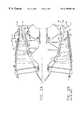
- FIG. 3is a perspective view illustration of a circumferentially extending portion of the fan exit guide vanes, struts, and splitter of the exemplary first embodiment of the present invention in the forward portion of aircraft gas turbine engine in FIG. 1;
- FIG. 4is an aft facing cross-sectional schematic illustration of one of the guide vanes in FIG. 3 taken through line 4 — 4 in FIG. 3;
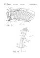
- FIG. 5is a cross-sectional illustrative view of an assembly of a fan blade, fan exit guide vane and strut of an exemplary aircraft gas turbine engine in accordance with a second embodiment of the present invention
- FIG. 6is a cross-sectional illustrative view of an assembly of a fan blade, fan exit guide vane and strut of an exemplary aircraft gas turbine engine in accordance with a third embodiment of the present invention.
- FIG. 7is a cross-sectional illustrative view of an assembly of a fan blade, fan exit guide vane and strut of an exemplary aircraft gas turbine engine in accordance with a fourth embodiment of the present invention.
- FIG. 1Illustrated in FIG. 1 is a schematic representation of a prior art aircraft gas turbine engine 10 in accordance with one embodiment of the present invention.
- the gas turbine engine 10is circumferentially disposed about an engine centerline 11 and has, in serial flow relationship, a fan section 12 , a high pressure compressor 16 , a combustion section 18 , a high pressure turbine 20 , and a low pressure turbine 22 .
- the fan section 12is illustrated as a multi-stage fan section having first, second, and third stage fan blades 12 A, 12 B, and 12 C, respectively, disposed within an annular fan duct 14 .
- the high pressure compressor 16 , the combustion section 18 and high pressure turbine 20are often referred to as a core engine 23 .
- a high pressure rotor shaft 24connects, in driving relationship, the high pressure turbine 20 to the high pressure compressor 16 and a low pressure rotor shaft 26 drivingly connects the low pressure turbine 22 to the fan section 12 .
- Fuelis burned in the combustion section 18 producing a very hot gas flow 28 which is directed through the high pressure and low pressure turbines 20 and 22 , respectively, to power the engine 10 .
- FIG. 2illustrates the fan section 12 of engine 10 with the present invention in a top half A of FIG. 2 as compared to the conventional version of fan section 12 in a bottom half B of FIG. 2 .
- fan air 40exits the fan section 12 through a plurality of fan exit guide vanes 50 which are circumferentially disposed around the centerline 11 directly aft of the third stage fan blade 12 C.
- An annular splitter 32splits the fan air 40 exiting the fan exit guide vanes 50 into a bypass air portion 42 bypassed around the core engine 23 through a bypass duct 30 and into a core engine air portion 43 passed through a diffusion duct 36 into the core engine.
- a fan frame 37including a circumferentially disposed plurality of structural struts 38 .
- the struts 38extend radially across a fan bypass inlet 44 of the bypass duct 30 and a core engine inlet 46 of diffusion duct 36 .
- the splitter 32is sectioned and attached to the struts 38 and splitter 32 extends axially between the fan bypass inlet 44 and the core engine inlet 46 .
- the fan exit guide vanes 50are conventional and unswept as are the struts 38 .
- the hot gas flow 28is discharged into an exhaust section 25 of the engine 10 where it is mixed with the bypass air portion 42 from the bypass duct 30 and exhausted through a variable nozzle 47 at the aft end of the engine 10 .
- An afterburner 49may be used for thrust augmentation.
- the exemplary engine 10 illustrated in FIG. 1is typical of a military gas turbine aircraft engine such as the General Electric F- 110 . This engine has 6 struts and 96 fan exit guide vanes.
- the fan exit guide vanes 50are axially swept having axially swept vane trailing edges TE and the struts 38 have strut leading edges LE that are axially swept to generally conform in shape to the axially swept trailing edges TE.
- the strut leading edges LEare closely spaced apart from the vane trailing edges TE with a small axially extending annular gap G between them.
- a forward swept vane embodiment of the fan exit guide vanes 50has airfoil portions which extend axially forwardly AF as it extends radially outwardly from a root 53 to a tip 55 of an airfoil 57 of the fan exit guide vane 50 and conversely an aft swept vane has airfoil portions which extend axially aftwardly AA as it extends radially outwardly from the root to tip.
- forward swept edges and aftward swept edgeshave edges which extend axially forwardly and axially aftwardly respectively as they extend radially outwardly from the root to tip of the airfoil.
- Conventional unswept airfoilsextend radially outwardly without forward or aftward extension. Aerodynamic forward sweep is discussed in U.S. Pat. No. 5,167,489 to Wadia et al.
- the axially swept vane trailing edges TE and the axially swept strut leading edges LEhave an aft inner and forward outer sweep in which radially inner edge portions 70 of these leading and trailing edges are swept aftwardly and radially outer edge portions 72 of these leading and trailing edges are swept forwardly.
- the change from aftwardly to forwardlyis preferably located at a radial distance from the centerline 11 corresponding to a radial location of a splitter leading edge 60 of the annular splitter 32 .
- the splitter leading edge 60is axially positioned aft of the strut leading edges.
- each of the fan exit guide vanes 50has pressure and suction sides 54 and 56 , respectively, and are leaned in a circumferential direction C such that the pressure side 54 facing radially inward RI towards the centerline 11 .
- the fan exit guide vanes 50are circumferentially leaned such that stacking lines SL of the vanes curve in a first circumferential direction C 1 in a first radial portion 58 of the vane and curve in a second circumferential direction C 2 in a second radial portion 59 of the vane.
- the fan exit guide vanes 50circumferentially have a lean indicated by the circumferentially extending shape of the stacking lines SL that is concentrated around a pitch line PL of the vanes between the first and second radial portions 58 and 59 , respectively, of the vane.
- the stacking lines SLare preferably substantially linear around the pitch lines PL.
- the axially swept and circumferentially leaned fan exit guide vanes 50reduce the amount of diffusion in the diffusion duct 36 along a radially inner duct wall 61 which recedes towards the centerline 11 in the axially aftwardly AA direction. It also is responsible for reducing the potential flow interaction between the stators and the struts relative to that produced by conventional radial fan exit guide vanes.
- the circumferential lean of the fan exit guide vanes 50lowers the exit Mach number at the root 53 of the vanes thus reducing the required duct velocity diffusion ratio. The amount of lean is such to tailor the flow radially inwards in towards the root 53 and an endwall 73 of the fan exit guide vanes 50 .
- the combination of the lean with axially aft sweep of vane airfoil 57moves a meridional projection of the trailing edge TE at midspan of the airfoil (about where the pitch line PL is) further aft relative to the axial position of the trailing edge at the root 53 .
- Thishelps prolong the benefit due to lean (lowering the inner wall Mach number) further downstream from the trailing edge at the root 53 and thereby providing better control of the diffusion along the inner duct wall 61 of the diffusion duct 36 particularly by preventing separation of the core flow 43 along the inner duct wall.
- the lean of the exit guide vanes 50causes more than one exit guide vane to circumferentially cross in front of each of the strut leading edges LE.
- the spread of these crossings to several exit guide vane passages P between the exit guide vanes 50it limits the effect of aerodynamic coupling between each passage and nearby strut 38 to small localized areas along each of the effected exit guide vanes 50 and to small radial lengths of the struts.
- This is so as the three-dimensional nature of the exit guide vanes designhelps the air flow to redistribute in both the radial and tangential directions to alleviate the back-pressure from the downstream strut.
- FIGS. 5, 6 , and 7illustrate second, third, and fourth embodiments of the shape or sweep of the axially swept vane trailing edges and strut leading edges.
- FIG. 5illustrates an the axially aft swept version of the third stage fan blades 12 C, the fan exit guide vanes 50 , the vane trailing edges TE, and the strut leading edges LE.
- FIG. 6illustrates an the axially forward swept version of the third stage fan blades 12 C, the fan exit guide vanes 50 , the vane trailing edges TE, and the strut leading edges LE.
- FIG. 5illustrates an the axially aft swept version of the third stage fan blades 12 C, the fan exit guide vanes 50 , the vane trailing edges TE, and the strut leading edges LE.
- FIG. 6illustrates an the axially forward swept version of the third stage fan blades 12 C, the fan exit guide vanes 50 , the vane trailing edges TE, and the
- FIG. 7illustrates an the axially curved swept version of the third stage fan blades 12 C, the fan exit guide vanes 50 , the vane trailing edges TE, and the strut leading edges LE, in which these elements are bowed in the axially aftwards direction.
Landscapes
- Engineering & Computer Science (AREA)
- Physics & Mathematics (AREA)
- Mechanical Engineering (AREA)
- General Engineering & Computer Science (AREA)
- Geometry (AREA)
- Fluid Mechanics (AREA)
- Structures Of Non-Positive Displacement Pumps (AREA)
Abstract
Description
Claims (16)
Priority Applications (1)
| Application Number | Priority Date | Filing Date | Title |
|---|---|---|---|
| US09/248,894US6195983B1 (en) | 1999-02-12 | 1999-02-12 | Leaned and swept fan outlet guide vanes |
Applications Claiming Priority (1)
| Application Number | Priority Date | Filing Date | Title |
|---|---|---|---|
| US09/248,894US6195983B1 (en) | 1999-02-12 | 1999-02-12 | Leaned and swept fan outlet guide vanes |
Publications (1)
| Publication Number | Publication Date |
|---|---|
| US6195983B1true US6195983B1 (en) | 2001-03-06 |
Family
ID=22941145
Family Applications (1)
| Application Number | Title | Priority Date | Filing Date |
|---|---|---|---|
| US09/248,894Expired - LifetimeUS6195983B1 (en) | 1999-02-12 | 1999-02-12 | Leaned and swept fan outlet guide vanes |
Country Status (1)
| Country | Link |
|---|---|
| US (1) | US6195983B1 (en) |
Cited By (109)
| Publication number | Priority date | Publication date | Assignee | Title |
|---|---|---|---|---|
| US6299412B1 (en)* | 1999-12-06 | 2001-10-09 | General Electric Company | Bowed compressor airfoil |
| US6354798B1 (en)* | 1997-09-08 | 2002-03-12 | Siemens Aktiengesellschaft | Blade for a fluid-flow machine, and steam turbine |
| US6554569B2 (en) | 2001-08-17 | 2003-04-29 | General Electric Company | Compressor outlet guide vane and diffuser assembly |
| US6554564B1 (en)* | 2001-11-14 | 2003-04-29 | United Technologies Corporation | Reduced noise fan exit guide vane configuration for turbofan engines |
| EP1462608A1 (en)* | 2003-03-27 | 2004-09-29 | Snecma Moteurs | Stator vane with double curvature |
| GB2402978A (en)* | 2003-06-18 | 2004-12-22 | Rolls Royce Plc | Gas turbine engine compressor stator arrangement and analysis method |
| US20050178105A1 (en)* | 2004-02-13 | 2005-08-18 | Honda Motor Co., Ltd. | Compressor and gas turbine engine |
| US20050257528A1 (en)* | 2004-05-19 | 2005-11-24 | Dunbar Donal S Jr | Retractable afterburner for jet engine |
| US20060016171A1 (en)* | 2004-07-23 | 2006-01-26 | Renggli Bernard J | Split shroud exhaust nozzle |
| US20060064961A1 (en)* | 2004-09-30 | 2006-03-30 | Johnson James E | Methods and apparatus for assembling a gas turbine engine |
| US20060067821A1 (en)* | 2004-09-28 | 2006-03-30 | Wadia Aspi R | Methods and apparatus for aerodynamically self-enhancing rotor blades |
| US20060133930A1 (en)* | 2004-12-21 | 2006-06-22 | Aggarwala Andrew S | Turbine engine guide vane and arrays thereof |
| US7074006B1 (en) | 2002-10-08 | 2006-07-11 | The United States Of America As Represented By The Administrator Of National Aeronautics And Space Administration | Endwall treatment and method for gas turbine |
| US20060210395A1 (en)* | 2004-09-28 | 2006-09-21 | Honeywell International, Inc. | Nonlinearly stacked low noise turbofan stator |
| US7140174B2 (en)* | 2004-09-30 | 2006-11-28 | General Electric Company | Methods and apparatus for assembling a gas turbine engine |
| GB2426792A (en)* | 2005-04-01 | 2006-12-06 | David Richard Hopkins | Fan with conical hub |
| GB2432637A (en)* | 2004-05-12 | 2007-05-30 | Rolls Royce Plc | A combination of an aircraft and a gas turbine engine |
| WO2007113149A1 (en)* | 2006-03-31 | 2007-10-11 | Alstom Technology Ltd | Guide blade for turbomachinery, in particular for a steam turbine |
| US20080010996A1 (en)* | 2003-07-29 | 2008-01-17 | Pratt & Whitney Canada Corp. | Turbofan case and method of making |
| US20080135679A1 (en)* | 2006-11-10 | 2008-06-12 | Rolls-Royce Plc | Turbine engine mounting arrangement |
| US20080159851A1 (en)* | 2006-12-29 | 2008-07-03 | Thomas Ory Moniz | Guide Vane and Method of Fabricating the Same |
| US20090068003A1 (en)* | 2007-09-06 | 2009-03-12 | United Technologies Corp. | Gas Turbine Engine Systems and Related Methods Involving Vane-Blade Count Ratios Greater than Unity |
| EP1333181A4 (en)* | 2001-05-24 | 2009-04-15 | Ihi Corp | Low noise fan stationary blade |
| US20090123276A1 (en)* | 2007-11-09 | 2009-05-14 | Alstom Technology Ltd | Steam turbine |
| RU2367798C2 (en)* | 2007-11-21 | 2009-09-20 | Иван Давыдович Востропятов | Turbojet engine |
| US20100054946A1 (en)* | 2008-09-04 | 2010-03-04 | John Orosa | Compressor blade with forward sweep and dihedral |
| US20100064656A1 (en)* | 2008-09-18 | 2010-03-18 | Honeywell International Inc. | Engines and methods of operating the same |
| US20100080697A1 (en)* | 2008-09-30 | 2010-04-01 | Wojno John P | Integrated guide vane assembly |
| US20100166591A1 (en)* | 2008-12-31 | 2010-07-01 | Kurt David Murrow | Positive displacement rotary components having main and gate rotors with axial flow inlets and outlets |
| US20100209238A1 (en)* | 2009-02-13 | 2010-08-19 | United Technologies Corporation | Turbine vane airfoil with turning flow and axial/circumferential trailing edge configuration |
| US20100247351A1 (en)* | 2009-03-31 | 2010-09-30 | Kleber Andreas | Axial flow fan, in particular for a motor vehicle |
| US20100260609A1 (en)* | 2006-11-30 | 2010-10-14 | General Electric Company | Advanced booster rotor blade |
| US20110001017A1 (en)* | 2008-12-08 | 2011-01-06 | Honeywell International Inc. | Uav ducted fan swept and lean stator design |
| WO2011124214A3 (en)* | 2010-04-10 | 2011-12-01 | Mtu Aero Engines Gmbh | Guide blade of a turbomachine |
| US20120014776A1 (en)* | 2006-04-25 | 2012-01-19 | Roy Fulayter | Method and apparatus for enhancing compressor performance |
| US8246292B1 (en) | 2012-01-31 | 2012-08-21 | United Technologies Corporation | Low noise turbine for geared turbofan engine |
| CN103062113A (en)* | 2013-01-23 | 2013-04-24 | 薛文义 | Fan mechanism of turbo-fan engine |
| US8468797B2 (en) | 2007-09-06 | 2013-06-25 | United Technologies Corporation | Gas turbine engine systems and related methods involving vane-blade count ratios greater than unity |
| US20130315726A1 (en)* | 2012-05-24 | 2013-11-28 | General Electric Company | Turbine and method for reducing shock losses in a turbine |
| US8632301B2 (en) | 2012-01-31 | 2014-01-21 | United Technologies Corporation | Low noise compressor rotor for geared turbofan engine |
| US8714913B2 (en) | 2012-01-31 | 2014-05-06 | United Technologies Corporation | Low noise compressor rotor for geared turbofan engine |
| US8764387B2 (en) | 2011-01-25 | 2014-07-01 | Rolls-Royce Corporation | Aggregate vane assembly |
| US8784050B2 (en) | 2010-06-15 | 2014-07-22 | Rolls-Royce Corporation | Aggregate vane assembly |
| US8834099B1 (en) | 2012-09-28 | 2014-09-16 | United Technoloiies Corporation | Low noise compressor rotor for geared turbofan engine |
| WO2014174214A1 (en)* | 2013-04-24 | 2014-10-30 | Aircelle | Flow-straightening structure for nacelle |
| WO2015023325A1 (en)* | 2013-08-12 | 2015-02-19 | United Technologies Corporation | Non-axisymmetric fan flow path |
| US8973374B2 (en) | 2007-09-06 | 2015-03-10 | United Technologies Corporation | Blades in a turbine section of a gas turbine engine |
| US20150226074A1 (en)* | 2012-07-06 | 2015-08-13 | Snecma | Turbomachine guide vanes with improved vane profile |
| US9121412B2 (en) | 2011-07-05 | 2015-09-01 | United Technologies Corporation | Efficient, low pressure ratio propulsor for gas turbine engines |
| US9121368B2 (en) | 2011-07-05 | 2015-09-01 | United Technologies Corporation | Efficient, low pressure ratio propulsor for gas turbine engines |
| US20150260051A1 (en)* | 2012-10-09 | 2015-09-17 | United Technologies Corporation | Geared low fan pressure ratio fan exit guide vane stagger angle |
| WO2015175056A2 (en) | 2014-02-19 | 2015-11-19 | United Technologies Corporation | Gas turbine engine airfoil |
| US20160076380A1 (en)* | 2014-09-15 | 2016-03-17 | United Technologies Corporation | Incidence-tolerant, high-turning fan exit stator |
| US9470093B2 (en) | 2015-03-18 | 2016-10-18 | United Technologies Corporation | Turbofan arrangement with blade channel variations |
| US9534498B2 (en) | 2012-12-14 | 2017-01-03 | United Technologies Corporation | Overmolded vane platform |
| EP3108112A4 (en)* | 2014-02-19 | 2017-02-22 | United Technologies Corporation | Gas turbine engine airfoil |
| US9624834B2 (en) | 2012-09-28 | 2017-04-18 | United Technologies Corporation | Low noise compressor rotor for geared turbofan engine |
| US9650965B2 (en) | 2012-09-28 | 2017-05-16 | United Technologies Corporation | Low noise compressor and turbine for geared turbofan engine |
| US9657646B2 (en) | 2012-04-25 | 2017-05-23 | General Electric Company | Aircraft engine driveshaft vessel assembly and method of assembling the same |
| EP3170973A1 (en)* | 2015-11-23 | 2017-05-24 | Rolls-Royce Corporation | Turbine engine flow path |
| GB2544653A (en)* | 2015-11-16 | 2017-05-24 | Safran Aircraft Engines | Turbomachine stator blade, fan casing comprising such a stator blade, thrust reverser system of a turbomachine with such a stator blade and turbomachine |
| US9719466B2 (en) | 2014-09-17 | 2017-08-01 | The Boeing Company | System and method for improved thrust reverser with increased reverse thrust and reduced noise |
| US9752439B2 (en) | 2014-02-19 | 2017-09-05 | United Technologies Corporation | Gas turbine engine airfoil |
| US9777580B2 (en) | 2014-02-19 | 2017-10-03 | United Technologies Corporation | Gas turbine engine airfoil |
| FR3050227A1 (en)* | 2016-04-18 | 2017-10-20 | Snecma | AUBE FIXED, IN PARTICULAR A FLOW RECTIFIER |
| EP3236012A1 (en)* | 2016-04-18 | 2017-10-25 | General Electric Company | Gas turbine engine transition duct and turbine center frame |
| US9909505B2 (en) | 2011-07-05 | 2018-03-06 | United Technologies Corporation | Efficient, low pressure ratio propulsor for gas turbine engines |
| US9909425B2 (en) | 2011-10-31 | 2018-03-06 | Pratt & Whitney Canada Corporation | Blade for a gas turbine engine |
| US20180073517A1 (en)* | 2016-09-09 | 2018-03-15 | United Technologies Corporation | Full-span forward swept airfoils for gas turbine engines |
| US10036257B2 (en) | 2014-02-19 | 2018-07-31 | United Technologies Corporation | Gas turbine engine airfoil |
| US20180231020A1 (en)* | 2017-02-14 | 2018-08-16 | Rolls-Royce Plc | Gas turbine engine fan blade with axial lean |
| US10184483B2 (en) | 2014-02-19 | 2019-01-22 | United Technologies Corporation | Gas turbine engine airfoil |
| FR3070448A1 (en)* | 2017-08-28 | 2019-03-01 | Safran Aircraft Engines | TURBOMACHINE BLOWER RECTIFIER DRAWER, TURBOMACHINE ASSEMBLY COMPRISING SUCH A BLADE AND TURBOMACHINE EQUIPPED WITH SAID DAUTH OR DUDIT TOGETHER |
| US10273812B2 (en) | 2015-12-18 | 2019-04-30 | Pratt & Whitney Canada Corp. | Turbine rotor coolant supply system |
| US10309414B2 (en) | 2014-02-19 | 2019-06-04 | United Technologies Corporation | Gas turbine engine airfoil |
| US10352331B2 (en) | 2014-02-19 | 2019-07-16 | United Technologies Corporation | Gas turbine engine airfoil |
| US10358925B2 (en) | 2014-02-19 | 2019-07-23 | United Technologies Corporation | Gas turbine engine airfoil |
| US10364773B2 (en)* | 2015-11-20 | 2019-07-30 | Rolls-Royce Plc | Gas turbine engine |
| US10370974B2 (en) | 2014-02-19 | 2019-08-06 | United Technologies Corporation | Gas turbine engine airfoil |
| US10385866B2 (en) | 2014-02-19 | 2019-08-20 | United Technologies Corporation | Gas turbine engine airfoil |
| US10393139B2 (en) | 2014-02-19 | 2019-08-27 | United Technologies Corporation | Gas turbine engine airfoil |
| US10422226B2 (en) | 2014-02-19 | 2019-09-24 | United Technologies Corporation | Gas turbine engine airfoil |
| US10495106B2 (en) | 2014-02-19 | 2019-12-03 | United Technologies Corporation | Gas turbine engine airfoil |
| US10502229B2 (en) | 2014-02-19 | 2019-12-10 | United Technologies Corporation | Gas turbine engine airfoil |
| US10519971B2 (en) | 2014-02-19 | 2019-12-31 | United Technologies Corporation | Gas turbine engine airfoil |
| US10550852B2 (en) | 2014-02-19 | 2020-02-04 | United Technologies Corporation | Gas turbine engine airfoil |
| US10557477B2 (en) | 2014-02-19 | 2020-02-11 | United Technologies Corporation | Gas turbine engine airfoil |
| US10563516B2 (en) | 2016-07-06 | 2020-02-18 | General Electric Company | Turbine engine and method of assembling |
| US10570916B2 (en) | 2014-02-19 | 2020-02-25 | United Technologies Corporation | Gas turbine engine airfoil |
| US10570915B2 (en) | 2014-02-19 | 2020-02-25 | United Technologies Corporation | Gas turbine engine airfoil |
| US10584715B2 (en) | 2014-02-19 | 2020-03-10 | United Technologies Corporation | Gas turbine engine airfoil |
| US10590775B2 (en) | 2014-02-19 | 2020-03-17 | United Technologies Corporation | Gas turbine engine airfoil |
| US10605259B2 (en) | 2014-02-19 | 2020-03-31 | United Technologies Corporation | Gas turbine engine airfoil |
| US11143109B2 (en) | 2013-03-14 | 2021-10-12 | Raytheon Technologies Corporation | Low noise turbine for geared gas turbine engine |
| US11168899B2 (en) | 2016-05-03 | 2021-11-09 | Carrier Corporation | Vane axial fan with intermediate flow control rings |
| US11255343B2 (en) | 2018-02-02 | 2022-02-22 | General Electric Company | Engine systems and methods |
| CN114297791A (en)* | 2021-12-09 | 2022-04-08 | 北京动力机械研究所 | Pneumatic vibration reduction design method for turbine guider |
| FR3122452A1 (en)* | 2021-04-30 | 2022-11-04 | Safran Helicopter Engines | Turbomachine subassembly produced by additive manufacturing |
| US11719161B2 (en) | 2013-03-14 | 2023-08-08 | Raytheon Technologies Corporation | Low noise turbine for geared gas turbine engine |
| US11873738B2 (en) | 2021-12-23 | 2024-01-16 | General Electric Company | Integrated stator-fan frame assembly |
| US12012898B2 (en) | 2022-11-03 | 2024-06-18 | General Electric Company | Gas turbine engine with acoustic spacing of the fan blades and outlet guide vanes |
| EP3792451B1 (en)* | 2019-09-12 | 2024-06-19 | Deutsches Zentrum für Luft- und Raumfahrt e.V. | Compressor stage with variable stator blade tilt |
| US12123432B2 (en) | 2012-01-31 | 2024-10-22 | Rtx Corporation | Low noise turbine for geared turbofan engine |
| US12209557B1 (en) | 2023-11-30 | 2025-01-28 | General Electric Company | Gas turbine engine with forward swept outlet guide vanes |
| US12292017B1 (en)* | 2024-06-14 | 2025-05-06 | General Electric Company | Gas turbine engine with acoustic spacing of the fan blades and outlet guide vanes |
| US12385430B2 (en) | 2023-11-30 | 2025-08-12 | General Electric Company | Gas turbine engine with forward swept outlet guide vanes |
| US12421854B1 (en)* | 2024-06-14 | 2025-09-23 | General Electric Company | Gas turbine engine with acoustic spacing of the fan blades and outlet guide vanes |
| US12429067B1 (en) | 2024-06-14 | 2025-09-30 | General Electric Company | Gas turbine engine with acoustic spacing of the fan blades and outlet guide vanes |
| US12428962B1 (en) | 2024-06-14 | 2025-09-30 | General Electric Company | Gas turbine engine with acoustic spacing of the fan blades and outlet guide vanes |
Citations (13)
| Publication number | Priority date | Publication date | Assignee | Title |
|---|---|---|---|---|
| US3922852A (en)* | 1973-10-17 | 1975-12-02 | Gen Electric | Variable pitch fan for gas turbine engine |
| US3986794A (en)* | 1975-06-09 | 1976-10-19 | General Motors Corporation | Reversible ducted fan assembly |
| US4013377A (en)* | 1975-10-08 | 1977-03-22 | Westinghouse Electric Corporation | Intermediate transition annulus for a two shaft gas turbine engine |
| US4504189A (en) | 1982-11-10 | 1985-03-12 | Rolls-Royce Limited | Stator vane for a gas turbine engine |
| US4682935A (en) | 1983-12-12 | 1987-07-28 | General Electric Company | Bowed turbine blade |
| US4714407A (en) | 1984-09-07 | 1987-12-22 | Rolls-Royce Plc | Aerofoil section members for turbine engines |
| US4741667A (en) | 1986-05-28 | 1988-05-03 | United Technologies Corporation | Stator vane |
| US4826400A (en) | 1986-12-29 | 1989-05-02 | General Electric Company | Curvilinear turbine airfoil |
| US5088892A (en) | 1990-02-07 | 1992-02-18 | United Technologies Corporation | Bowed airfoil for the compression section of a rotary machine |
| US5167489A (en) | 1991-04-15 | 1992-12-01 | General Electric Company | Forward swept rotor blade |
| US5642985A (en) | 1995-11-17 | 1997-07-01 | United Technologies Corporation | Swept turbomachinery blade |
| US5725354A (en) | 1996-11-22 | 1998-03-10 | General Electric Company | Forward swept fan blade |
| US5782077A (en)* | 1995-05-15 | 1998-07-21 | Aerospatiale Societe Nationale Industrielle | Device for bleeding off and cooling hot air in an aircraft engine |
- 1999
- 1999-02-12USUS09/248,894patent/US6195983B1/ennot_activeExpired - Lifetime
Patent Citations (13)
| Publication number | Priority date | Publication date | Assignee | Title |
|---|---|---|---|---|
| US3922852A (en)* | 1973-10-17 | 1975-12-02 | Gen Electric | Variable pitch fan for gas turbine engine |
| US3986794A (en)* | 1975-06-09 | 1976-10-19 | General Motors Corporation | Reversible ducted fan assembly |
| US4013377A (en)* | 1975-10-08 | 1977-03-22 | Westinghouse Electric Corporation | Intermediate transition annulus for a two shaft gas turbine engine |
| US4504189A (en) | 1982-11-10 | 1985-03-12 | Rolls-Royce Limited | Stator vane for a gas turbine engine |
| US4682935A (en) | 1983-12-12 | 1987-07-28 | General Electric Company | Bowed turbine blade |
| US4714407A (en) | 1984-09-07 | 1987-12-22 | Rolls-Royce Plc | Aerofoil section members for turbine engines |
| US4741667A (en) | 1986-05-28 | 1988-05-03 | United Technologies Corporation | Stator vane |
| US4826400A (en) | 1986-12-29 | 1989-05-02 | General Electric Company | Curvilinear turbine airfoil |
| US5088892A (en) | 1990-02-07 | 1992-02-18 | United Technologies Corporation | Bowed airfoil for the compression section of a rotary machine |
| US5167489A (en) | 1991-04-15 | 1992-12-01 | General Electric Company | Forward swept rotor blade |
| US5782077A (en)* | 1995-05-15 | 1998-07-21 | Aerospatiale Societe Nationale Industrielle | Device for bleeding off and cooling hot air in an aircraft engine |
| US5642985A (en) | 1995-11-17 | 1997-07-01 | United Technologies Corporation | Swept turbomachinery blade |
| US5725354A (en) | 1996-11-22 | 1998-03-10 | General Electric Company | Forward swept fan blade |
Non-Patent Citations (7)
| Title |
|---|
| "Concept And Design Of Stator Tailored To Shield A Fan From Pressure Disturbances Arising In The Downstream Fan Duct", by P.E. Rubbert and R.D. LaPrete, AIAA 10th Aeorspace Sciences Meeting, AIAA Paper No. 72-74, Jan. 17-19, 1972, pp. 1-8. |
| "OGV Tailoring to Alleviate Pylon-OGV-Fan Interaction", by G.N. Shrinivas and M.B. Giles, The American Society Of Mechanical Engineers, Presented at the International Gas Turbine and Aeroengine Congress & Exposition, Jun. 5-8, 1995, pp. 1-9. |
| "Optimisation Of Bypass Fan Outlet Guide Vanes", by A.B. Parry, The American Society Of Mechanical Engineers, Presented at the International Gas Turbine and Aeroengine Congress & Exhibition, Jun. 10-13, 1996, pp. 1-8. |
| "Potential Pressure Field by Stator / Downstream Strut Interaction", by H. Kodama & S. Nagano, Journal of Turbomachinery, Apr. 1989, vol. 111, pp. 197-203. |
| "Sensitivity Analysis and Optimum Design Method for Reduced Rotor-Stator-Strut Flow Interaction", by G. Cerri & W.F. O'Brien, Journal of Turbomachinery, Oct. 1989, vol. 111, pp. 401-203. |
| "The Use Of Circumferentially Nonuniform Stators To Attenuate LP Compressor Rotor-Stator-Strut Aerodynamic And Mechanical Interactions", by M.G. Jones, M.T. Barton and W.F. O'Brien, The American Society Of Mechanical Engineers, Presented at the International Gas Turbine and Aeroengine Congress & Exhibition, Jun. 10-13, 1996, pp. 1-8. |
| "The Use Of Cyclic Variations In Strut Stagger To Reduce Coupled Blade-Vane-Strut-Pylon Interaction And System Losses", by A.B. Parry and R.H. Bailey, The American Society Of Mechanical Engineers, Presented at the International Gas Turbine and Aeroengine Congress & Exhibition, Jun. 2-5, 1997, pp. 1-8. |
Cited By (198)
| Publication number | Priority date | Publication date | Assignee | Title |
|---|---|---|---|---|
| US6354798B1 (en)* | 1997-09-08 | 2002-03-12 | Siemens Aktiengesellschaft | Blade for a fluid-flow machine, and steam turbine |
| US6299412B1 (en)* | 1999-12-06 | 2001-10-09 | General Electric Company | Bowed compressor airfoil |
| EP1333181A4 (en)* | 2001-05-24 | 2009-04-15 | Ihi Corp | Low noise fan stationary blade |
| US6554569B2 (en) | 2001-08-17 | 2003-04-29 | General Electric Company | Compressor outlet guide vane and diffuser assembly |
| US6554564B1 (en)* | 2001-11-14 | 2003-04-29 | United Technologies Corporation | Reduced noise fan exit guide vane configuration for turbofan engines |
| US7074006B1 (en) | 2002-10-08 | 2006-07-11 | The United States Of America As Represented By The Administrator Of National Aeronautics And Space Administration | Endwall treatment and method for gas turbine |
| EP1462608A1 (en)* | 2003-03-27 | 2004-09-29 | Snecma Moteurs | Stator vane with double curvature |
| FR2853022A1 (en)* | 2003-03-27 | 2004-10-01 | Snecma Moteurs | DOUBLE CURVED RECTIFIER BLADE |
| US20060222488A1 (en)* | 2003-03-27 | 2006-10-05 | Snecma Moteurs | Nozzle vane with two slopes |
| US7121792B1 (en)* | 2003-03-27 | 2006-10-17 | Snecma Moteurs | Nozzle vane with two slopes |
| GB2402978A (en)* | 2003-06-18 | 2004-12-22 | Rolls Royce Plc | Gas turbine engine compressor stator arrangement and analysis method |
| US7444802B2 (en) | 2003-06-18 | 2008-11-04 | Rolls-Royce Plc | Gas turbine engine including stator vanes having variable camber and stagger configurations at different circumferential positions |
| GB2402978B (en)* | 2003-06-18 | 2007-08-08 | Rolls Royce Plc | A combination of an aircraft and a gas turbine engine |
| US20040258520A1 (en)* | 2003-06-18 | 2004-12-23 | Parry Anthony B. | Gas turbine engine |
| US20080010996A1 (en)* | 2003-07-29 | 2008-01-17 | Pratt & Whitney Canada Corp. | Turbofan case and method of making |
| US7739866B2 (en)* | 2003-07-29 | 2010-06-22 | Pratt & Whitney Canada Corp. | Turbofan case and method of making |
| US7437877B2 (en)* | 2004-02-13 | 2008-10-21 | Honda Motor Co., Ltd. | Compressor having low-pressure and high-pressure compressor operating at optimum ratio between pressure ratios thereof and gas turbine engine adopting the same |
| US20050178105A1 (en)* | 2004-02-13 | 2005-08-18 | Honda Motor Co., Ltd. | Compressor and gas turbine engine |
| GB2432637B (en)* | 2004-05-12 | 2007-08-08 | Rolls Royce Plc | A combination of an aircraft and a gas turbine engine |
| GB2435309B (en)* | 2004-05-12 | 2007-10-10 | Rolls Royce Plc | A combination of an aircraft and a gas turbine engine |
| GB2435309A (en)* | 2004-05-12 | 2007-08-22 | Rolls Royce Plc | A combination of an aircraft and a gas turbine engine |
| GB2432637A (en)* | 2004-05-12 | 2007-05-30 | Rolls Royce Plc | A combination of an aircraft and a gas turbine engine |
| US7334409B2 (en)* | 2004-05-19 | 2008-02-26 | Alltech, Inc. | Retractable afterburner for jet engine |
| US20050257528A1 (en)* | 2004-05-19 | 2005-11-24 | Dunbar Donal S Jr | Retractable afterburner for jet engine |
| US20060016171A1 (en)* | 2004-07-23 | 2006-01-26 | Renggli Bernard J | Split shroud exhaust nozzle |
| US7174704B2 (en)* | 2004-07-23 | 2007-02-13 | General Electric Company | Split shroud exhaust nozzle |
| US7320575B2 (en) | 2004-09-28 | 2008-01-22 | General Electric Company | Methods and apparatus for aerodynamically self-enhancing rotor blades |
| US7547186B2 (en) | 2004-09-28 | 2009-06-16 | Honeywell International Inc. | Nonlinearly stacked low noise turbofan stator |
| GB2434183A (en)* | 2004-09-28 | 2007-07-18 | Honeywell Int Inc | Nonlinearly stacked low noise turbofan stator vane |
| WO2007001389A3 (en)* | 2004-09-28 | 2007-04-19 | Honeywell Int Inc | Nonlinearly stacked low noise turbofan stator vane |
| GB2434183B (en)* | 2004-09-28 | 2009-07-29 | Honeywell Int Inc | Nonlinearly stacked low noise turbofan stator vane |
| US20060067821A1 (en)* | 2004-09-28 | 2006-03-30 | Wadia Aspi R | Methods and apparatus for aerodynamically self-enhancing rotor blades |
| US20060210395A1 (en)* | 2004-09-28 | 2006-09-21 | Honeywell International, Inc. | Nonlinearly stacked low noise turbofan stator |
| US7188467B2 (en)* | 2004-09-30 | 2007-03-13 | General Electric Company | Methods and apparatus for assembling a gas turbine engine |
| US20060064961A1 (en)* | 2004-09-30 | 2006-03-30 | Johnson James E | Methods and apparatus for assembling a gas turbine engine |
| US7140174B2 (en)* | 2004-09-30 | 2006-11-28 | General Electric Company | Methods and apparatus for assembling a gas turbine engine |
| US7195456B2 (en) | 2004-12-21 | 2007-03-27 | United Technologies Corporation | Turbine engine guide vane and arrays thereof |
| US20060133930A1 (en)* | 2004-12-21 | 2006-06-22 | Aggarwala Andrew S | Turbine engine guide vane and arrays thereof |
| GB2426792A (en)* | 2005-04-01 | 2006-12-06 | David Richard Hopkins | Fan with conical hub |
| GB2426792B (en)* | 2005-04-01 | 2007-06-27 | David Richard Hopkins | A design to increase and smoothly improve the throughput of fluid (air or gas) through the inlet fan (or fans) of an aero-engine system |
| CN101460706B (en)* | 2006-03-31 | 2012-02-08 | 阿尔斯通技术有限公司 | Guide vane for a turbomachine, in particular for a steam turbine |
| US20110164970A1 (en)* | 2006-03-31 | 2011-07-07 | Alstom Technology Ltd | Stator blade for a turbomachine, especially a stream turbine |
| JP2009531593A (en)* | 2006-03-31 | 2009-09-03 | アルストム テクノロジー リミテッド | Guide blades for fluid machinery, especially steam turbines |
| US20090257866A1 (en)* | 2006-03-31 | 2009-10-15 | Alstom Technology Ltd. | Stator blade for a turbomachine, especially a steam turbine |
| WO2007113149A1 (en)* | 2006-03-31 | 2007-10-11 | Alstom Technology Ltd | Guide blade for turbomachinery, in particular for a steam turbine |
| US8500399B2 (en)* | 2006-04-25 | 2013-08-06 | Rolls-Royce Corporation | Method and apparatus for enhancing compressor performance |
| US20120014776A1 (en)* | 2006-04-25 | 2012-01-19 | Roy Fulayter | Method and apparatus for enhancing compressor performance |
| US20080135679A1 (en)* | 2006-11-10 | 2008-06-12 | Rolls-Royce Plc | Turbine engine mounting arrangement |
| US7845158B2 (en) | 2006-11-10 | 2010-12-07 | Rolls-Royce Plc | Turbine engine mounting arrangement |
| US7967571B2 (en)* | 2006-11-30 | 2011-06-28 | General Electric Company | Advanced booster rotor blade |
| US20100260609A1 (en)* | 2006-11-30 | 2010-10-14 | General Electric Company | Advanced booster rotor blade |
| JP2008163950A (en)* | 2006-12-29 | 2008-07-17 | General Electric Co <Ge> | Guide vane and method of fabricating the same |
| EP1942253A3 (en)* | 2006-12-29 | 2011-08-24 | General Electric Company | Guide vane and method of fabricating the same |
| US20080159851A1 (en)* | 2006-12-29 | 2008-07-03 | Thomas Ory Moniz | Guide Vane and Method of Fabricating the Same |
| US7984607B2 (en) | 2007-09-06 | 2011-07-26 | United Technologies Corp. | Gas turbine engine systems and related methods involving vane-blade count ratios greater than unity |
| US8973374B2 (en) | 2007-09-06 | 2015-03-10 | United Technologies Corporation | Blades in a turbine section of a gas turbine engine |
| US8468797B2 (en) | 2007-09-06 | 2013-06-25 | United Technologies Corporation | Gas turbine engine systems and related methods involving vane-blade count ratios greater than unity |
| US20090068003A1 (en)* | 2007-09-06 | 2009-03-12 | United Technologies Corp. | Gas Turbine Engine Systems and Related Methods Involving Vane-Blade Count Ratios Greater than Unity |
| US8516793B2 (en) | 2007-09-06 | 2013-08-27 | United Technologies Corp. | Gas turbine engine systems and related methods involving vane-blade count ratios greater than unity |
| US20090123276A1 (en)* | 2007-11-09 | 2009-05-14 | Alstom Technology Ltd | Steam turbine |
| US8167548B2 (en) | 2007-11-09 | 2012-05-01 | Alstom Technology Ltd. | Steam turbine |
| RU2367798C2 (en)* | 2007-11-21 | 2009-09-20 | Иван Давыдович Востропятов | Turbojet engine |
| US20100054946A1 (en)* | 2008-09-04 | 2010-03-04 | John Orosa | Compressor blade with forward sweep and dihedral |
| US8147207B2 (en) | 2008-09-04 | 2012-04-03 | Siemens Energy, Inc. | Compressor blade having a ratio of leading edge sweep to leading edge dihedral in a range of 1:1 to 3:1 along the radially outer portion |
| US20100064656A1 (en)* | 2008-09-18 | 2010-03-18 | Honeywell International Inc. | Engines and methods of operating the same |
| US20100080697A1 (en)* | 2008-09-30 | 2010-04-01 | Wojno John P | Integrated guide vane assembly |
| US8221071B2 (en) | 2008-09-30 | 2012-07-17 | General Electric Company | Integrated guide vane assembly |
| US20110001017A1 (en)* | 2008-12-08 | 2011-01-06 | Honeywell International Inc. | Uav ducted fan swept and lean stator design |
| US20100166591A1 (en)* | 2008-12-31 | 2010-07-01 | Kurt David Murrow | Positive displacement rotary components having main and gate rotors with axial flow inlets and outlets |
| US8328542B2 (en) | 2008-12-31 | 2012-12-11 | General Electric Company | Positive displacement rotary components having main and gate rotors with axial flow inlets and outlets |
| US20100209238A1 (en)* | 2009-02-13 | 2010-08-19 | United Technologies Corporation | Turbine vane airfoil with turning flow and axial/circumferential trailing edge configuration |
| US8075259B2 (en) | 2009-02-13 | 2011-12-13 | United Technologies Corporation | Turbine vane airfoil with turning flow and axial/circumferential trailing edge configuration |
| US20100247351A1 (en)* | 2009-03-31 | 2010-09-30 | Kleber Andreas | Axial flow fan, in particular for a motor vehicle |
| US8459967B2 (en)* | 2009-03-31 | 2013-06-11 | Behr Gmbh & Co. Kg | Axial flow fan, in particular for a motor vehicle |
| US8613592B2 (en) | 2010-04-10 | 2013-12-24 | Mtu Aero Engines Gmbh | Guide blade of a turbomachine |
| WO2011124214A3 (en)* | 2010-04-10 | 2011-12-01 | Mtu Aero Engines Gmbh | Guide blade of a turbomachine |
| US8784050B2 (en) | 2010-06-15 | 2014-07-22 | Rolls-Royce Corporation | Aggregate vane assembly |
| US8764387B2 (en) | 2011-01-25 | 2014-07-01 | Rolls-Royce Corporation | Aggregate vane assembly |
| US9926885B2 (en) | 2011-07-05 | 2018-03-27 | United Technologies Corporation | Efficient, low pressure ratio propulsor for gas turbine engines |
| US9121412B2 (en) | 2011-07-05 | 2015-09-01 | United Technologies Corporation | Efficient, low pressure ratio propulsor for gas turbine engines |
| US9909505B2 (en) | 2011-07-05 | 2018-03-06 | United Technologies Corporation | Efficient, low pressure ratio propulsor for gas turbine engines |
| US10288009B2 (en) | 2011-07-05 | 2019-05-14 | United Technologies Corporation | Efficient, low pressure ratio propulsor for gas turbine engines |
| US10605202B2 (en) | 2011-07-05 | 2020-03-31 | United Technologies Corporation | Efficient, low pressure ratio propulsor for gas turbine engines |
| US10012150B2 (en) | 2011-07-05 | 2018-07-03 | United Technologies Corporation | Efficient, low pressure ratio propulsor for gas turbine engines |
| US11073157B2 (en) | 2011-07-05 | 2021-07-27 | Raytheon Technologies Corporation | Efficient, low pressure ratio propulsor for gas turbine engines |
| US10233868B2 (en) | 2011-07-05 | 2019-03-19 | United Technologies Corporation | Efficient, low pressure ratio propulsor for gas turbine engines |
| US9506422B2 (en) | 2011-07-05 | 2016-11-29 | United Technologies Corporation | Efficient, low pressure ratio propulsor for gas turbine engines |
| US9121368B2 (en) | 2011-07-05 | 2015-09-01 | United Technologies Corporation | Efficient, low pressure ratio propulsor for gas turbine engines |
| US9909425B2 (en) | 2011-10-31 | 2018-03-06 | Pratt & Whitney Canada Corporation | Blade for a gas turbine engine |
| US8517668B1 (en) | 2012-01-31 | 2013-08-27 | United Technologies Corporation | Low noise turbine for geared turbofan engine |
| US12123432B2 (en) | 2012-01-31 | 2024-10-22 | Rtx Corporation | Low noise turbine for geared turbofan engine |
| US8632301B2 (en) | 2012-01-31 | 2014-01-21 | United Technologies Corporation | Low noise compressor rotor for geared turbofan engine |
| US8714913B2 (en) | 2012-01-31 | 2014-05-06 | United Technologies Corporation | Low noise compressor rotor for geared turbofan engine |
| US8246292B1 (en) | 2012-01-31 | 2012-08-21 | United Technologies Corporation | Low noise turbine for geared turbofan engine |
| US9657646B2 (en) | 2012-04-25 | 2017-05-23 | General Electric Company | Aircraft engine driveshaft vessel assembly and method of assembling the same |
| US9121285B2 (en)* | 2012-05-24 | 2015-09-01 | General Electric Company | Turbine and method for reducing shock losses in a turbine |
| US20130315726A1 (en)* | 2012-05-24 | 2013-11-28 | General Electric Company | Turbine and method for reducing shock losses in a turbine |
| US20150226074A1 (en)* | 2012-07-06 | 2015-08-13 | Snecma | Turbomachine guide vanes with improved vane profile |
| US10844735B2 (en) | 2012-07-06 | 2020-11-24 | Safran Aircraft Engines | Turbomachine guide vanes with improved vane profile |
| US9624834B2 (en) | 2012-09-28 | 2017-04-18 | United Technologies Corporation | Low noise compressor rotor for geared turbofan engine |
| US9726019B2 (en) | 2012-09-28 | 2017-08-08 | United Technologies Corporation | Low noise compressor rotor for geared turbofan engine |
| US8834099B1 (en) | 2012-09-28 | 2014-09-16 | United Technoloiies Corporation | Low noise compressor rotor for geared turbofan engine |
| US9650965B2 (en) | 2012-09-28 | 2017-05-16 | United Technologies Corporation | Low noise compressor and turbine for geared turbofan engine |
| US9733266B2 (en) | 2012-09-28 | 2017-08-15 | United Technologies Corporation | Low noise compressor and turbine for geared turbofan engine |
| US20150260051A1 (en)* | 2012-10-09 | 2015-09-17 | United Technologies Corporation | Geared low fan pressure ratio fan exit guide vane stagger angle |
| US10738627B2 (en) | 2012-10-09 | 2020-08-11 | Raytheon Technologies Corporation | Geared low fan pressure ratio fan exit guide vane stagger angle |
| US9869191B2 (en)* | 2012-10-09 | 2018-01-16 | United Technologies Corporation | Geared low fan pressure ratio fan exit guide vane stagger angle |
| US9534498B2 (en) | 2012-12-14 | 2017-01-03 | United Technologies Corporation | Overmolded vane platform |
| CN103062113A (en)* | 2013-01-23 | 2013-04-24 | 薛文义 | Fan mechanism of turbo-fan engine |
| US11719161B2 (en) | 2013-03-14 | 2023-08-08 | Raytheon Technologies Corporation | Low noise turbine for geared gas turbine engine |
| US11143109B2 (en) | 2013-03-14 | 2021-10-12 | Raytheon Technologies Corporation | Low noise turbine for geared gas turbine engine |
| US11168614B2 (en) | 2013-03-14 | 2021-11-09 | Raytheon Technologies Corporation | Low noise turbine for geared gas turbine engine |
| US11560849B2 (en) | 2013-03-14 | 2023-01-24 | Raytheon Technologies Corporation | Low noise turbine for geared gas turbine engine |
| WO2014174214A1 (en)* | 2013-04-24 | 2014-10-30 | Aircelle | Flow-straightening structure for nacelle |
| FR3005120A1 (en)* | 2013-04-24 | 2014-10-31 | Aircelle Sa | FLOW RECOVERY STRUCTURE FOR NACELLE |
| WO2015023325A1 (en)* | 2013-08-12 | 2015-02-19 | United Technologies Corporation | Non-axisymmetric fan flow path |
| US10415505B2 (en) | 2013-08-12 | 2019-09-17 | United Technologies Corporation | Non-axisymmetric fan flow path |
| US10570916B2 (en) | 2014-02-19 | 2020-02-25 | United Technologies Corporation | Gas turbine engine airfoil |
| US10393139B2 (en) | 2014-02-19 | 2019-08-27 | United Technologies Corporation | Gas turbine engine airfoil |
| EP3108112A4 (en)* | 2014-02-19 | 2017-02-22 | United Technologies Corporation | Gas turbine engine airfoil |
| US9988908B2 (en) | 2014-02-19 | 2018-06-05 | United Technologies Corporation | Gas turbine engine airfoil |
| US20160341213A1 (en)* | 2014-02-19 | 2016-11-24 | United Technologies Corporation | Gas turbine engine airfoil |
| US10036257B2 (en) | 2014-02-19 | 2018-07-31 | United Technologies Corporation | Gas turbine engine airfoil |
| US20170167267A1 (en)* | 2014-02-19 | 2017-06-15 | United Technologies Corporation | Gas turbine engine airfoil |
| US11041507B2 (en) | 2014-02-19 | 2021-06-22 | Raytheon Technologies Corporation | Gas turbine engine airfoil |
| US10184483B2 (en) | 2014-02-19 | 2019-01-22 | United Technologies Corporation | Gas turbine engine airfoil |
| US11408436B2 (en) | 2014-02-19 | 2022-08-09 | Raytheon Technologies Corporation | Gas turbine engine airfoil |
| US11391294B2 (en) | 2014-02-19 | 2022-07-19 | Raytheon Technologies Corporation | Gas turbine engine airfoil |
| US10914315B2 (en) | 2014-02-19 | 2021-02-09 | Raytheon Technologies Corporation | Gas turbine engine airfoil |
| US11209013B2 (en) | 2014-02-19 | 2021-12-28 | Raytheon Technologies Corporation | Gas turbine engine airfoil |
| US9752439B2 (en) | 2014-02-19 | 2017-09-05 | United Technologies Corporation | Gas turbine engine airfoil |
| US10890195B2 (en) | 2014-02-19 | 2021-01-12 | Raytheon Technologies Corporation | Gas turbine engine airfoil |
| US10309414B2 (en) | 2014-02-19 | 2019-06-04 | United Technologies Corporation | Gas turbine engine airfoil |
| US11193496B2 (en) | 2014-02-19 | 2021-12-07 | Raytheon Technologies Corporation | Gas turbine engine airfoil |
| US10352331B2 (en) | 2014-02-19 | 2019-07-16 | United Technologies Corporation | Gas turbine engine airfoil |
| US9777580B2 (en) | 2014-02-19 | 2017-10-03 | United Technologies Corporation | Gas turbine engine airfoil |
| US10358925B2 (en) | 2014-02-19 | 2019-07-23 | United Technologies Corporation | Gas turbine engine airfoil |
| US11867195B2 (en) | 2014-02-19 | 2024-01-09 | Rtx Corporation | Gas turbine engine airfoil |
| US10370974B2 (en) | 2014-02-19 | 2019-08-06 | United Technologies Corporation | Gas turbine engine airfoil |
| US10385866B2 (en) | 2014-02-19 | 2019-08-20 | United Technologies Corporation | Gas turbine engine airfoil |
| EP3108122A4 (en)* | 2014-02-19 | 2017-03-01 | United Technologies Corporation | Gas turbine engine airfoil |
| US11767856B2 (en) | 2014-02-19 | 2023-09-26 | Rtx Corporation | Gas turbine engine airfoil |
| US10422226B2 (en) | 2014-02-19 | 2019-09-24 | United Technologies Corporation | Gas turbine engine airfoil |
| US10465702B2 (en)* | 2014-02-19 | 2019-11-05 | United Technologies Corporation | Gas turbine engine airfoil |
| US10495106B2 (en) | 2014-02-19 | 2019-12-03 | United Technologies Corporation | Gas turbine engine airfoil |
| US10502229B2 (en) | 2014-02-19 | 2019-12-10 | United Technologies Corporation | Gas turbine engine airfoil |
| US10519971B2 (en) | 2014-02-19 | 2019-12-31 | United Technologies Corporation | Gas turbine engine airfoil |
| US10550852B2 (en) | 2014-02-19 | 2020-02-04 | United Technologies Corporation | Gas turbine engine airfoil |
| US10557477B2 (en) | 2014-02-19 | 2020-02-11 | United Technologies Corporation | Gas turbine engine airfoil |
| US11193497B2 (en) | 2014-02-19 | 2021-12-07 | Raytheon Technologies Corporation | Gas turbine engine airfoil |
| WO2015175056A2 (en) | 2014-02-19 | 2015-11-19 | United Technologies Corporation | Gas turbine engine airfoil |
| US10570915B2 (en) | 2014-02-19 | 2020-02-25 | United Technologies Corporation | Gas turbine engine airfoil |
| US10584715B2 (en) | 2014-02-19 | 2020-03-10 | United Technologies Corporation | Gas turbine engine airfoil |
| US10590775B2 (en) | 2014-02-19 | 2020-03-17 | United Technologies Corporation | Gas turbine engine airfoil |
| US10605259B2 (en) | 2014-02-19 | 2020-03-31 | United Technologies Corporation | Gas turbine engine airfoil |
| US20160076380A1 (en)* | 2014-09-15 | 2016-03-17 | United Technologies Corporation | Incidence-tolerant, high-turning fan exit stator |
| US10060263B2 (en)* | 2014-09-15 | 2018-08-28 | United Technologies Corporation | Incidence-tolerant, high-turning fan exit stator |
| US9719466B2 (en) | 2014-09-17 | 2017-08-01 | The Boeing Company | System and method for improved thrust reverser with increased reverse thrust and reduced noise |
| US11118459B2 (en) | 2015-03-18 | 2021-09-14 | Aytheon Technologies Corporation | Turbofan arrangement with blade channel variations |
| US10358924B2 (en) | 2015-03-18 | 2019-07-23 | United Technologies Corporation | Turbofan arrangement with blade channel variations |
| US9470093B2 (en) | 2015-03-18 | 2016-10-18 | United Technologies Corporation | Turbofan arrangement with blade channel variations |
| US11466572B2 (en) | 2015-03-18 | 2022-10-11 | Raytheon Technologies Corporation | Gas turbine engine with blade channel variations |
| GB2544653A (en)* | 2015-11-16 | 2017-05-24 | Safran Aircraft Engines | Turbomachine stator blade, fan casing comprising such a stator blade, thrust reverser system of a turbomachine with such a stator blade and turbomachine |
| GB2544653B (en)* | 2015-11-16 | 2021-04-28 | Safran Aircraft Engines | Turbine engine variable stator vane with incurved profile and thrust reverser system |
| US10364773B2 (en)* | 2015-11-20 | 2019-07-30 | Rolls-Royce Plc | Gas turbine engine |
| US10294862B2 (en) | 2015-11-23 | 2019-05-21 | Rolls-Royce Corporation | Turbine engine flow path |
| EP3170973A1 (en)* | 2015-11-23 | 2017-05-24 | Rolls-Royce Corporation | Turbine engine flow path |
| US10273812B2 (en) | 2015-12-18 | 2019-04-30 | Pratt & Whitney Canada Corp. | Turbine rotor coolant supply system |
| US10907490B2 (en) | 2015-12-18 | 2021-02-02 | Pratt & Whitney Canada Corp. | Turbine rotor coolant supply system |
| US10344602B2 (en) | 2016-04-18 | 2019-07-09 | General Electric Company | Gas turbine engine transition duct and turbine center frame |
| FR3050227A1 (en)* | 2016-04-18 | 2017-10-20 | Snecma | AUBE FIXED, IN PARTICULAR A FLOW RECTIFIER |
| EP3236012A1 (en)* | 2016-04-18 | 2017-10-25 | General Electric Company | Gas turbine engine transition duct and turbine center frame |
| US11226114B2 (en) | 2016-05-03 | 2022-01-18 | Carrier Corporation | Inlet for axial fan |
| US11168899B2 (en) | 2016-05-03 | 2021-11-09 | Carrier Corporation | Vane axial fan with intermediate flow control rings |
| US10563516B2 (en) | 2016-07-06 | 2020-02-18 | General Electric Company | Turbine engine and method of assembling |
| US20180073517A1 (en)* | 2016-09-09 | 2018-03-15 | United Technologies Corporation | Full-span forward swept airfoils for gas turbine engines |
| EP3296508A1 (en)* | 2016-09-09 | 2018-03-21 | United Technologies Corporation | Full-span forward swept airfoils for gas turbine engines |
| US10605260B2 (en)* | 2016-09-09 | 2020-03-31 | United Technologies Corporation | Full-span forward swept airfoils for gas turbine engines |
| US20180231020A1 (en)* | 2017-02-14 | 2018-08-16 | Rolls-Royce Plc | Gas turbine engine fan blade with axial lean |
| EP3676480B1 (en) | 2017-08-28 | 2022-10-05 | Safran Aircraft Engines | Turbomachine fan flow-straightener vane, turbomachine assembly comprising such a vane, and turbomachine equipped with said vane or with said assembly |
| FR3070448A1 (en)* | 2017-08-28 | 2019-03-01 | Safran Aircraft Engines | TURBOMACHINE BLOWER RECTIFIER DRAWER, TURBOMACHINE ASSEMBLY COMPRISING SUCH A BLADE AND TURBOMACHINE EQUIPPED WITH SAID DAUTH OR DUDIT TOGETHER |
| WO2019043330A1 (en)* | 2017-08-28 | 2019-03-07 | Safran Aircraft Engines | Turbomachine fan flow-straightener vane, turbomachine assembly comprising such a vane, and turbomachine equipped with said vane or with said assembly |
| US11377958B2 (en)* | 2017-08-28 | 2022-07-05 | Safran Aircraft Engines | Turbomachine fan flow-straightener vane, turbomachine assembly comprising such a vane and turbomachine equipped with said vane or said assembly |
| US12117019B2 (en) | 2018-02-02 | 2024-10-15 | General Electric Company | Engine systems and methods |
| CN115288854A (en)* | 2018-02-02 | 2022-11-04 | 通用电气公司 | Engine system and method |
| US11649834B2 (en) | 2018-02-02 | 2023-05-16 | General Electric Company | Engine systems and methods |
| US11255343B2 (en) | 2018-02-02 | 2022-02-22 | General Electric Company | Engine systems and methods |
| EP3792451B1 (en)* | 2019-09-12 | 2024-06-19 | Deutsches Zentrum für Luft- und Raumfahrt e.V. | Compressor stage with variable stator blade tilt |
| FR3122452A1 (en)* | 2021-04-30 | 2022-11-04 | Safran Helicopter Engines | Turbomachine subassembly produced by additive manufacturing |
| CN114297791A (en)* | 2021-12-09 | 2022-04-08 | 北京动力机械研究所 | Pneumatic vibration reduction design method for turbine guider |
| US11873738B2 (en) | 2021-12-23 | 2024-01-16 | General Electric Company | Integrated stator-fan frame assembly |
| US12012898B2 (en) | 2022-11-03 | 2024-06-18 | General Electric Company | Gas turbine engine with acoustic spacing of the fan blades and outlet guide vanes |
| US12209557B1 (en) | 2023-11-30 | 2025-01-28 | General Electric Company | Gas turbine engine with forward swept outlet guide vanes |
| US12385430B2 (en) | 2023-11-30 | 2025-08-12 | General Electric Company | Gas turbine engine with forward swept outlet guide vanes |
| US12292017B1 (en)* | 2024-06-14 | 2025-05-06 | General Electric Company | Gas turbine engine with acoustic spacing of the fan blades and outlet guide vanes |
| US12421854B1 (en)* | 2024-06-14 | 2025-09-23 | General Electric Company | Gas turbine engine with acoustic spacing of the fan blades and outlet guide vanes |
| US12429067B1 (en) | 2024-06-14 | 2025-09-30 | General Electric Company | Gas turbine engine with acoustic spacing of the fan blades and outlet guide vanes |
| US12428962B1 (en) | 2024-06-14 | 2025-09-30 | General Electric Company | Gas turbine engine with acoustic spacing of the fan blades and outlet guide vanes |
Similar Documents
| Publication | Publication Date | Title |
|---|---|---|
| US6195983B1 (en) | Leaned and swept fan outlet guide vanes | |
| JP4953924B2 (en) | FLADE fan with different inner and outer airfoil stagger angles in the position of the shroud between the inner and outer airfoils | |
| CA2548133C (en) | Counterrotating turbofan engine | |
| US7631484B2 (en) | High pressure ratio aft fan | |
| EP1731716B1 (en) | Forward tilted turbine nozzle | |
| JP5177959B2 (en) | Low solidity turbofan | |
| US20210239132A1 (en) | Variable-cycle compressor with a splittered rotor | |
| CA2548361C (en) | Integrated counterrotating turbofan | |
| US8082727B2 (en) | Rear propulsor for a variable cycle gas turbine engine | |
| US10385871B2 (en) | Method and system for compressor vane leading edge auxiliary vanes | |
| US11719168B2 (en) | Compressor apparatus with bleed slot and supplemental flange | |
| US3956887A (en) | Gas turbine engines | |
| US20160153465A1 (en) | Axial compressor endwall treatment for controlling leakage flow therein | |
| WO1998009066A1 (en) | Variable pressure and variable air flow gas turbine engines | |
| JPS6039866B2 (en) | Split fan gas turbine engine | |
| EP3485146B1 (en) | Turbofan engine and corresponding method of operating | |
| US20180313364A1 (en) | Compressor apparatus with bleed slot including turning vanes | |
| CA2958886A1 (en) | Gas turbine engine with an offtake | |
| US10519976B2 (en) | Fluid diodes with ridges to control boundary layer in axial compressor stator vane | |
| US20140234095A1 (en) | Aerofoil for axial-flow machine | |
| CA3075160A1 (en) | Tandem stators with flow recirculation conduit | |
| EP3464823A1 (en) | System for a low swirl low pressure turbine |
Legal Events
| Date | Code | Title | Description |
|---|---|---|---|
| AS | Assignment | Owner name:GENERAL ELECTRIC COMPANY, NEW YORK Free format text:ASSIGNMENT OF ASSIGNORS INTEREST;ASSIGNORS:WADIA, ASPI R.;SZUCS, PETER N.;HEMMELGARN, BRUCE A.;REEL/FRAME:009766/0307;SIGNING DATES FROM 19990201 TO 19990208 | |
| AS | Assignment | Owner name:AIR FORCE, UNITED STATES, OHIO Free format text:CONFIRMATORY LICENSE;ASSIGNOR:GENERAL ELECTRIC COMPANY;REEL/FRAME:009936/0014 Effective date:19990412 | |
| AS | Assignment | Owner name:UNITED STATES AIR FORCE, OHIO Free format text:CONFIRMATORY LICENSE;ASSIGNOR:GE AIRCRAFT ENGINES;REEL/FRAME:010093/0616 Effective date:19990528 | |
| STCF | Information on status: patent grant | Free format text:PATENTED CASE | |
| AS | Assignment | Owner name:SNOWY VILLAGE, INC., MINNESOTA Free format text:ASSIGNMENT OF ASSIGNORS INTEREST;ASSIGNORS:PEDERSON, JOHN C.;SEVERSON, DAN;SEVERSON, CATHY JO;REEL/FRAME:011569/0587 Effective date:20010215 | |
| FPAY | Fee payment | Year of fee payment:4 | |
| REMI | Maintenance fee reminder mailed | ||
| FPAY | Fee payment | Year of fee payment:8 | |
| SULP | Surcharge for late payment | Year of fee payment:7 | |
| FPAY | Fee payment | Year of fee payment:12 |