US6195608B1 - Acoustic highway monitor - Google Patents
Acoustic highway monitorDownload PDFInfo
- Publication number
- US6195608B1 US6195608B1US09/074,563US7456398AUS6195608B1US 6195608 B1US6195608 B1US 6195608B1US 7456398 AUS7456398 AUS 7456398AUS 6195608 B1US6195608 B1US 6195608B1
- Authority
- US
- United States
- Prior art keywords
- vertical
- microphone
- electric transducers
- microphone elements
- acoustic
- Prior art date
- Legal status (The legal status is an assumption and is not a legal conclusion. Google has not performed a legal analysis and makes no representation as to the accuracy of the status listed.)
- Expired - Lifetime
Links
Images


Classifications
- G—PHYSICS
- G08—SIGNALLING
- G08G—TRAFFIC CONTROL SYSTEMS
- G08G1/00—Traffic control systems for road vehicles
- G08G1/01—Detecting movement of traffic to be counted or controlled
- G—PHYSICS
- G08—SIGNALLING
- G08G—TRAFFIC CONTROL SYSTEMS
- G08G1/00—Traffic control systems for road vehicles
- G08G1/01—Detecting movement of traffic to be counted or controlled
- G08G1/04—Detecting movement of traffic to be counted or controlled using optical or ultrasonic detectors
Definitions
- the present inventionrelates to highway monitoring systems in general and, more specifically, to systems which detect and signal the existence of a motor vehicle within a predetermined detection zone on the roadway.
- Highway departmentsuse a variety of techniques to monitor traffic in an effort to detect, mitigate, and prevent congestion.
- each highway departmenthas a command center that receives and integrates a plurality of signals which are transmitted by monitoring systems located along the highway.
- monitoring systemslocated along the highway.
- the most prevalent systememploys a roadway metal detector.
- a wire loopis embedded in the roadway and its terminals are connected to detection circuitry that measures the inductance changes in the wire loop. Because the inductance in the wire loop is perturbed by a motor vehicle (comprising a quantity of ferromagnetic material) passing over it, the detection circuitry can detect when a motor vehicle is over the wire loop.
- the detection circuitryBased on this perturbation, the detection circuitry creates a binary signal, called a “loop relay signal,” which is transmitted to the command center of the highway department.
- the command centergathers the respective loop relay signals and from there makes a determination as to the likelihood of congestion.
- the use of wire loopsis, however, disadvantageous for several reasons.
- a wire loop systemwill not detect a motor vehicle unless the motor vehicle comprises a sufficient ferromagnetic material to create a noticeable perturbation in the inductance in the wire loop. Because the trend is to fabricate motor vehicles with non-ferromagnetic alloys, plastics and composite materials, wire loop systems will increasingly fail to detect the presence of motor vehicles. It is already well known that wire loops often overlook small vehicles. Another disadvantage of wire loop systems is that they are expensive to install and maintain. Installation and repair require that a lane be closed, that the roadway be cut and that the cut be sealed. Often too, harsh weather can preclude this operation for several months.
- U.S. Pat. No. 5,060,206patented Oct. 22, 1991, by F. C. de Metz, Sr., entitled “Marine Acoustic Aerobuoy and Method of Operation,” provided a marine acoustic detector for use in identifying a characteristic airborne sound pressure field generated by a propeller-driven aircraft.
- the detectorincluded a surface-buoyed resonator chamber which was tuned to the narrow frequency band of the airborne sound pressure field and which had a dimensioned opening formed into a first endplate of the chamber for admitting the airborne sound pressure field.
- Mounted within the resonator chamberwas a transducer circuit comprising a microphone and a preamplifier.
- the microphonefunctioned to detect the resonating sound pressure field within the chamber and to convert the resonating sound waves into an electrical signal.
- the preamplifierfunctioned to amplify the electrical signal for transmission via a cable to an underwater or surface marine vehicle to undergo signal processing.
- the sound amplification properties of the resonator air chamberwere exploited in the passive detection of propeller-driven aircraft at airborne ranges exceeding those ranges of visual or sonar detection to provide 44 dB of received sound amplification at common aircraft frequencies below 100 Hz.
- this patentused only a single electro-acoustic transducer for receiving acoustic signals within a detection zone, and did not teach spatial discrimination circuitry for representing acoustic energy emanating from a detection zone.
- U.S. Pat. No. 3,047,838, patented Jul. 31, 1962, by G. D. Hendricks, entitled “Traffic Cycle Length Selector”provided a traffic cycle length selector which automatically related the duration of a traffic signal cycle to the volume of traffic in the direction of heavier traffic along a throughfare.
- the Hendricks systemdid not teach the use of electro-acoustic transducers, but instead used pressure-sensitive detectors. While Hendricks employed plural, non-electro-acoustic transducers, the traffic cycle length selector system did not include spatial discrimination circuitry. Hendricks merely described the use of the output of several spatially discriminate detectors to generate a spatially indiscriminate signal.
- One object of the present inventionis to provide apparatus and method to monitor highway traffic while avoiding many of the costs and restrictions associated with prior techniques.
- Another object of the present inventionis to provide such apparatus which can be installed and maintained in any weather and which does not require that the roadway be closed, torn-up or repaved.
- the present inventionprovides apparatus for detecting vehicles moving through a predetermined zone, comprising: (a) a plurality of acousto-electric transducers trained on that zone; (b) bandpass filtering means for processing electrical signals from the plurality of acousto-electric transducers; (c) correlator means having at least two inputs and an output for correlating filtered versions of the electrical signals originating from at least two of the plurality of acousto-electric transducers; (d) integrator means for integrating the output of the correlator means over time; and (e) comparator means for indicating detection of a vehicle when the integrated output exceeds a predetermined threshold.
- the present inventionalso provides a method for detecting vehicles moving through a predetermined zone, comprising the steps of: (a) training a plurality of acousto-electric transducers on that zone; (b) filtering electrical signals from the plurality acousto-electric transducers; (c) correlating at least two of the filtered electrical signals with one another; (d) integrating the results of correlation in step (c) over time; and (e) comparing the integrated result of step (d) to a predetermined threshold and indicating detection of a vehicle when the threshold is exceeded by the integrated result.
- the apparatusfurther includes a plurality of analog-to-digital converter means for converting said electrical signals to digital representations prior to the processing thereof.
- the integrator and the comparator meansare each microprocessor-based programs.
- the plurality of acousto-electric transducerscomprises two vertical and two horizontal multiple-microphone elements
- the correlator meanshas one of the at least two inputs receiving a sum of the two multiple-microphone vertical elements, and the other of the at least two inputs receiving a sum of the two horizontal multiple-microphone elements.
- the methodfurther includes the step of converting said electrical signals to digital representations prior to said filtering.
- the steps of integrating and comparingare each computational routines.
- the plurality of acousto-electric transducerscomprises two vertical and two horizontal multiple-microphone elements, and the correlating step continuously correlates the sum of the two vertical multiple-microphone elements with sums of the two horizontal multiple-microphone elements.
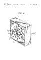
- FIG. 1is a drawing of an illustrative embodiment of the present invention as it is used to monitor the presence or absence of a motor vehicle in a predetermined detection zone;
- FIG. 2is a drawing of an illustrative microphone array as can be used in the illustrative embodiment of the present invention
- FIG. 3is a block diagram of the internals of an illustrative detection circuit as shown in FIG. 1;
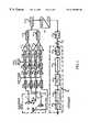
- FIG. 4is a detailed block diagram of a preferred embodiment of the acoustic highway monitor according to the present invention.
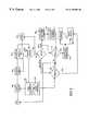
- FIG. 5is a flowchart showing the operation of the controller block shown in FIG. 4 .
- Each motor vehicle using a highwayradiates acoustic energy from the power plant (e.g., the engine block, pumps, fans, belts, etc.) and from its motion along the roadway (e.g., tire noise due to friction, wind flow noise, etc.). While the energy fills the frequency band from DC up to approximately 16 KHz, there is a reliable presence of energy from about 3 KHz to about 8 KHz. Embodiments of the present invention exploit this observation for the purpose of highway surveillance.
- the power plante.g., the engine block, pumps, fans, belts, etc.
- the motion along the roadwaye.g., tire noise due to friction, wind flow noise, etc.
- FIG. 1depicts an illustrative embodiment of the present invention that monitors a predetermined area of roadway, called a “predetermined detection zone,” for the presence of a motor vehicle within that area.
- the salient items in FIG. 1are roadway 101 , motor vehicle 103 , motor vehicle 105 , detection zone 107 , microphone array 111 , microphone support 109 , detection circuit 115 and interface circuit 119 in a roadside cabinet (not shown), electrical bus 113 , electrical bus 117 and lead 121 .
- Each omni-directional microphone in microphone array 111receives an acoustic signal which comprises the sound radiated, inter alia, from motor vehicle 103 , motor vehicle 105 and ambient noise. Each microphone in microphone array 111 then transforms its respective acoustic signal into an analog electric signal and outputs the analog electric signal on a distinct lead on electrical bus 113 in ordinary fashion. The respective analog electric signals are then fed into detection circuit 115 .
- the respective signals from microphone array 111are processed in ordinary fashion to provide the sensory spatial discrimination needed to isolate sounds emanating from within predetermined detection zone 107 .
- the ability to control the spatial directivity of microphone array 111is called “beam-forming.” It will be clear to those skilled in the art that electronically-controlled steerable beams can be used to form multiple detection zones.
- microphone array 111preferably comprises a plurality of acoustic transducers (e.g., omni-directional microphones), arranged in a geometrical arrangement known as a Mill's Cross.
- acoustic transducerse.g., omni-directional microphones
- Mill's Cross arraysthe interested reader is directed to Microwave Scanning Antenna , R. C. Hensen, E., Academic Press (1964), and Principals of Underwater Sound (3rd. Ed), R. J. Urick (1983).
- microphone array 111could comprise only one microphone, the benefits of multiple microphones (to provide signal gain and directivity, whether in a fully or sparsely populated array or vector), will be clear to those skilled in the art.
- baffle microphone array 111mechanically so as to attenuate sounds coming from other than predetermined detection zone 107 and to protect microphone array 111 from the environment (e.g., rain, snow, wind, UV).
- Microphone array 111is advantageously rigidly mounted on support 109 so that the predetermined relative spatial positionings of the individual microphones are maintained.
- a typical deployment geometryis shown in FIG. 1 .
- the horizontal distance of the sensor from the nearest lane with trafficis assumed to be less than about 15 feet.
- the vertical height above the roadis advantageously between about 20 and about 35 feet, depending on performance requirements and available mounting facilities.
- the deployment geometryis flexible and can be modified for specific objectives.
- it will also be clear to those skilled in the arthow to position and orient microphone array 111 so that it is well suited to receive sounds from predetermined detection zone 107 .
- detection circuit 115advantageously comprises bus 301 , vertical summer 305 , analog-to-digital converter 313 , finite-impulse-response filter 317 , bus 303 , horizontal summer 307 , analog-to-digital converter 315 , finite-impulse-response filter 319 , multiplier 321 and comparator 325 .
- the electric signals from microphone 201 , microphone 203 , microphone 205 , microphone 207 and microphone 209are fed, via bus 301 , into vertical summer 305 which adds them in well-known fashion and feeds the sum into analog-to-digital converter 313 .
- vertical summer 305performs an unweighted addition of the respective signals
- vertical summer 305can alternately perform a weighted addition of the respective signals so as to shape and steer the formed beam (i.e., to change the position of predetermined detection zone 107 ).
- illustrative embodiments of the present inventioncan comprise two or more detection circuits, so that one microphone array can gather the data for two or more detection zones, in each lane or in different lanes.
- Analog-to-digital converter 313receives the output of vertical summer 305 and samples it at 32,000 samples per second in well-known fashion. The output of analog-to-digital converter 313 is fed into finite-impulse response filter 317 .
- Finite-impulse response filter 317is preferably a bandpass filter with a lower passband edge of 4 KHz, an upper passband edge of 6 KHz and a stopband rejection level of 60 dB below the passband (i.e., stopband levels providing 60 dB of rejection). It will be clear to those skilled in the art how to make and use finite-impulse-response filter 317 .
- horizontal summer 307performs an unweighted addition of the respective signals, it will be clear to those skilled in the art that horizontal summer 307 can alternately perform a weighted addition of the respective signals so as to shape and steer the formed beam (i.e., to change the position of predetermined detection zone 107 ).
- Analog-to-digital converter 315receives the output of horizontal summer 305 , and samples it at 32,000 samples per second in well-known fashion. The output of analog-to-digital converter 313 is fed into finite-impulse response filter 319 .
- Finite-impulse response filter 319is preferably a bandpass filter with a lower passband edge of 4 KHz, an upper passband edge of 6 KHz and a stopband rejection level of 60 dB below the passband (i.e., stopband levels providing 60 dB of rejection). It will be clear to those skilled in the art how to make and use finite-impulse-response filter 319 .
- Multiplier 321receives, as input, the output of finite-impulse-response filter 317 and finite-response-filter 319 and performs a sample-by-sample multiplication of the respective inputs and then performs a coherent averaging of the respective products.
- the output of multiplier 321is fed into comparator 325 . It will be clear to those skilled in the art how to make and use multiplier 321 .
- Comparator 325advantageously, on a sample-by-sample basis, compares the magnitude of each sample to a predetermined threshold and creates a binary signal which indicates whether a motor vehicle is within predetermined detection zone 107 . While the predetermined threshold can be a constant, it will be clear to those skilled in the art that the predetermined threshold can be adaptable to various weather conditions and/or other environmental conditions which can change over time.
- the output of comparator 325is fed into interface circuitry 119 .
- Interface circuitry 119receives the output of detection circuitry 115 and preferable creates an output signal such that the output signal is asserted when a motor vehicle is within predetermined detection zone 107 and such that the output signal is retracted when there is no motor vehicle within the predetermined detection zone 107 .
- Interface circuitry 119also makes any electrical conversions necessary to interface to the circuitry at the command center of the highway department.
- Interface circuitry 119can also perform statistical analysis on the output of the detection circuitry 115 so as to output a signal which has other characteristics than those described above.
- FIG. 4 of the drawingsillustrates an exemplary implementation using digital processing components to a great extent.
- the microphone array 400comprises two vertical elements V 1 and V 2 , and two horizontal elements H 1 and H 2 . As shown, each element has three microphones.
- Each of the four elements V 1 , V 2 , H 1 , and H 2feeds a respective analog filter 401 - 404 to attenuate unwanted noise outside the maximal frequency band of interest, which is normally between about 4 and about 9 kHz.
- the filters 401 - 404are each followed by a selectable gain preamplifier 405 - 408 , the gain of which is selectable in 3-dB steps ranging from 0 dB to 15 dB (hereto to be described more fully later).
- Respective digital finite impulse response (FIR) filters 413 - 416follow the A/D converters 409 - 412 .
- the FIR filters 413 - 416determine the actual frequency band of operation, which is selected, e.g., from the following four bands:
- the selection of the frequency bandwould normally depend on the general nature of the expected vehicle traffic at the particular location of the sensor.
- the selected gainwould depend, in addition, on the distance of the sensor from the road surface.
- the outputs of the FIR filters 413 and 414(the paths of V 1 and V 2 ) are summed in digital summer 417
- the outputs of the FIR filters 415 and 416(the paths of H 1 and H 2 ) are summed in digital summer 418 .
- the respective digital summers 417 and 418are followed by digital limiters 419 and 420 , respectively, and the outputs of the latter are input to correlator 421 , the output of which is fed to a parallel-to-serial converter 422 , the serial output of which would normally be fed to a TDMA multiplexer (TDMA-MUX) 423 to be time-division multiplexed with other (conveniently four) processed microphone array signals originating from overhead locations near the array 400 .
- TDMA-MUXTDMA multiplexer
- the multiplexed output of TDMA-MUX 423is then normally relayed by cable 424 to roadside microprocessor-based controller 425 , where it is demultiplexed in DEMUX 426 into the original number of serial outputs representing the serial outputs of correlators, e.g., 421 .
- DEMUX 426After demultiplexing in DEMUX 426 , the cross-correlated digital output from the correlator 421 is intergrated in integrator 427 (which could be a software routine in the microprocessor/controller 425 ), and, depending on the correlated/integrated signal level, which is compared to a threshold in vehicle detector 428 , a “vehicle present” signal is issued for the duration above threshold.
- integrator 427which could be a software routine in the microprocessor/controller 425
- a “vehicle present” signalis issued for the duration above threshold.
- This informationis processed by a flow parameter calculation routine 429 of the controller 425
- the operation of the controller 425whereby the demultiplexed signal from DEMUX 426 is processed, will be better explained by reference to the flow-chart shown in FIG. 5 .
- the signalis adjusted in gain/offset 500 depending on user specific parameters 501 and then sampled 502 and integrated 503 .
- the signal sampling 503continues until enough samples 504 have been collected, upon which the integrator 503 is reset 505 and the mode (i.e., whether the controller is used to indicate only vehicle presence or to monitor traffic flow) is determined 506 . If the mode is to indicate vehicle presence (for example, to switch a traffic light from red to green), and a vehicle is detected 507 , the decision is immediately output 508 .
- variable thresholdis used to continue to determine vehicle presence 510 , and to calculate flow parameters 511 .
- the flow parameters 511are stored in memory 512 and output 508 over the RS 232 serial link to (other) central traffic management systems (not shown), and where desired activate other interface circuits.
- the binary vehicle presence decision 507is determined by a user-selected fixed threshold 513 .
Landscapes
- Physics & Mathematics (AREA)
- General Physics & Mathematics (AREA)
- Traffic Control Systems (AREA)
Abstract
Description
This invention is a continuation-in-part of application Ser. No. 08/069,957, filed May 28, 1993, now U.S. Pat. No. 6,021,364, the entire contents of which are incorporated herein by reference.
The present invention relates to highway monitoring systems in general and, more specifically, to systems which detect and signal the existence of a motor vehicle within a predetermined detection zone on the roadway.
Highway departments use a variety of techniques to monitor traffic in an effort to detect, mitigate, and prevent congestion. Typically, each highway department has a command center that receives and integrates a plurality of signals which are transmitted by monitoring systems located along the highway. Although different kinds of monitoring systems are used, the most prevalent system employs a roadway metal detector. In such system, a wire loop is embedded in the roadway and its terminals are connected to detection circuitry that measures the inductance changes in the wire loop. Because the inductance in the wire loop is perturbed by a motor vehicle (comprising a quantity of ferromagnetic material) passing over it, the detection circuitry can detect when a motor vehicle is over the wire loop. Based on this perturbation, the detection circuitry creates a binary signal, called a “loop relay signal,” which is transmitted to the command center of the highway department. The command center gathers the respective loop relay signals and from there makes a determination as to the likelihood of congestion. The use of wire loops is, however, disadvantageous for several reasons.
First, a wire loop system will not detect a motor vehicle unless the motor vehicle comprises a sufficient ferromagnetic material to create a noticeable perturbation in the inductance in the wire loop. Because the trend is to fabricate motor vehicles with non-ferromagnetic alloys, plastics and composite materials, wire loop systems will increasingly fail to detect the presence of motor vehicles. It is already well known that wire loops often overlook small vehicles. Another disadvantage of wire loop systems is that they are expensive to install and maintain. Installation and repair require that a lane be closed, that the roadway be cut and that the cut be sealed. Often too, harsh weather can preclude this operation for several months.
Other non-invasive systems have been suggested. U.S. Pat. No. 5,060,206, patented Oct. 22, 1991, by F. C. de Metz, Sr., entitled “Marine Acoustic Aerobuoy and Method of Operation,” provided a marine acoustic detector for use in identifying a characteristic airborne sound pressure field generated by a propeller-driven aircraft. The detector included a surface-buoyed resonator chamber which was tuned to the narrow frequency band of the airborne sound pressure field and which had a dimensioned opening formed into a first endplate of the chamber for admitting the airborne sound pressure field. Mounted within the resonator chamber was a transducer circuit comprising a microphone and a preamplifier. The microphone functioned to detect the resonating sound pressure field within the chamber and to convert the resonating sound waves into an electrical signal. The preamplifier functioned to amplify the electrical signal for transmission via a cable to an underwater or surface marine vehicle to undergo signal processing. The sound amplification properties of the resonator air chamber were exploited in the passive detection of propeller-driven aircraft at airborne ranges exceeding those ranges of visual or sonar detection to provide 44 dB of received sound amplification at common aircraft frequencies below 100 Hz. However, this patent used only a single electro-acoustic transducer for receiving acoustic signals within a detection zone, and did not teach spatial discrimination circuitry for representing acoustic energy emanating from a detection zone.
U.S. Pat. No. 3,445,637, patented May 20, 1969, by J. M. Auer, Jr., entitled “Apparatus For Measuring Traffic Density” provided apparatus for measuring traffic density in which a sonic detector produced a discrete signal which was inversely proportional only to vehicle speed for each passing vehicle. A meter, which was responsive to the discrete signals, produced a measurement representative of traffic density. However, this patent used only a single electro-acoustic transducer for receiving acoustic signals within a detection zone, and did not teach spatial discrimination circuitry for representing acoustic energy emanating from a detection zone.
U.S. Pat. No. 3,047,838, patented Jul. 31, 1962, by G. D. Hendricks, entitled “Traffic Cycle Length Selector” provided a traffic cycle length selector which automatically related the duration of a traffic signal cycle to the volume of traffic in the direction of heavier traffic along a throughfare. The Hendricks system did not teach the use of electro-acoustic transducers, but instead used pressure-sensitive detectors. While Hendricks employed plural, non-electro-acoustic transducers, the traffic cycle length selector system did not include spatial discrimination circuitry. Hendricks merely described the use of the output of several spatially discriminate detectors to generate a spatially indiscriminate signal.
Aims of the Invention
One object of the present invention is to provide apparatus and method to monitor highway traffic while avoiding many of the costs and restrictions associated with prior techniques.
Another object of the present invention is to provide such apparatus which can be installed and maintained in any weather and which does not require that the roadway be closed, torn-up or repaved.
Statements of Invention
The present invention provides apparatus for detecting vehicles moving through a predetermined zone, comprising: (a) a plurality of acousto-electric transducers trained on that zone; (b) bandpass filtering means for processing electrical signals from the plurality of acousto-electric transducers; (c) correlator means having at least two inputs and an output for correlating filtered versions of the electrical signals originating from at least two of the plurality of acousto-electric transducers; (d) integrator means for integrating the output of the correlator means over time; and (e) comparator means for indicating detection of a vehicle when the integrated output exceeds a predetermined threshold.
The present invention also provides a method for detecting vehicles moving through a predetermined zone, comprising the steps of: (a) training a plurality of acousto-electric transducers on that zone; (b) filtering electrical signals from the plurality acousto-electric transducers; (c) correlating at least two of the filtered electrical signals with one another; (d) integrating the results of correlation in step (c) over time; and (e) comparing the integrated result of step (d) to a predetermined threshold and indicating detection of a vehicle when the threshold is exceeded by the integrated result.
Other Features of the Invention
By one feature of this invention, the apparatus further includes a plurality of analog-to-digital converter means for converting said electrical signals to digital representations prior to the processing thereof.
By a further feature of this invention, the integrator and the comparator means are each microprocessor-based programs.
By still another feature of this invention, the plurality of acousto-electric transducers comprises two vertical and two horizontal multiple-microphone elements, and the correlator means has one of the at least two inputs receiving a sum of the two multiple-microphone vertical elements, and the other of the at least two inputs receiving a sum of the two horizontal multiple-microphone elements.
By one feature of the method of this invention, the method further includes the step of converting said electrical signals to digital representations prior to said filtering. By a feature of such feature, the steps of integrating and comparing are each computational routines.
By another feature of the method of this invention, the plurality of acousto-electric transducers comprises two vertical and two horizontal multiple-microphone elements, and the correlating step continuously correlates the sum of the two vertical multiple-microphone elements with sums of the two horizontal multiple-microphone elements.
FIG. 1 is a drawing of an illustrative embodiment of the present invention as it is used to monitor the presence or absence of a motor vehicle in a predetermined detection zone;
FIG. 2 is a drawing of an illustrative microphone array as can be used in the illustrative embodiment of the present invention;
FIG. 3 is a block diagram of the internals of an illustrative detection circuit as shown in FIG. 1;
FIG. 4 is a detailed block diagram of a preferred embodiment of the acoustic highway monitor according to the present invention; and
FIG. 5 is a flowchart showing the operation of the controller block shown in FIG.4.
Each motor vehicle using a highway radiates acoustic energy from the power plant (e.g., the engine block, pumps, fans, belts, etc.) and from its motion along the roadway (e.g., tire noise due to friction, wind flow noise, etc.). While the energy fills the frequency band from DC up to approximately 16 KHz, there is a reliable presence of energy from about 3 KHz to about 8 KHz. Embodiments of the present invention exploit this observation for the purpose of highway surveillance.
Description of FIG. 1
FIG. 1 depicts an illustrative embodiment of the present invention that monitors a predetermined area of roadway, called a “predetermined detection zone,” for the presence of a motor vehicle within that area. The salient items in FIG. 1 areroadway 101,motor vehicle 103,motor vehicle 105,detection zone 107,microphone array 111,microphone support 109,detection circuit 115 andinterface circuit 119 in a roadside cabinet (not shown),electrical bus 113,electrical bus 117 and lead121.
Each omni-directional microphone inmicrophone array 111 receives an acoustic signal which comprises the sound radiated, inter alia, frommotor vehicle 103,motor vehicle 105 and ambient noise. Each microphone inmicrophone array 111 then transforms its respective acoustic signal into an analog electric signal and outputs the analog electric signal on a distinct lead onelectrical bus 113 in ordinary fashion. The respective analog electric signals are then fed intodetection circuit 115.
To determine the presence or passage of a motor vehicle inpredetermined detection zone 107, the respective signals frommicrophone array 111 are processed in ordinary fashion to provide the sensory spatial discrimination needed to isolate sounds emanating from withinpredetermined detection zone 107. The ability to control the spatial directivity ofmicrophone array 111 is called “beam-forming.” It will be clear to those skilled in the art that electronically-controlled steerable beams can be used to form multiple detection zones.
Description of FIG. 2
As shown in FIG. 2,microphone array 111 preferably comprises a plurality of acoustic transducers (e.g., omni-directional microphones), arranged in a geometrical arrangement known as a Mill's Cross. For information regarding Mill's Cross arrays, the interested reader is directed toMicrowave Scanning Antenna, R. C. Hensen, E., Academic Press (1964), andPrincipals of Underwater Sound(3rd. Ed), R. J. Urick (1983). Whilemicrophone array 111 could comprise only one microphone, the benefits of multiple microphones (to provide signal gain and directivity, whether in a fully or sparsely populated array or vector), will be clear to those skilled in the art. It will also be clear to those skilled in the art how to bafflemicrophone array 111 mechanically so as to attenuate sounds coming from other thanpredetermined detection zone 107 and to protectmicrophone array 111 from the environment (e.g., rain, snow, wind, UV).Microphone array 111 is advantageously rigidly mounted onsupport 109 so that the predetermined relative spatial positionings of the individual microphones are maintained. A typical deployment geometry is shown in FIG.1. For this geometry, the horizontal distance of the sensor from the nearest lane with traffic is assumed to be less than about 15 feet. The vertical height above the road is advantageously between about 20 and about 35 feet, depending on performance requirements and available mounting facilities. It will be clear to those skilled in the art that the deployment geometry is flexible and can be modified for specific objectives. Furthermore, it will also be clear to those skilled in the art how to position and orientmicrophone array 111 so that it is well suited to receive sounds frompredetermined detection zone 107.
Description of FIG. 3
Referring to FIG. 3,detection circuit 115 advantageously comprisesbus 301,vertical summer 305, analog-to-digital converter 313, finite-impulse-response filter 317,bus 303,horizontal summer 307, analog-to-digital converter 315, finite-impulse-response filter 319,multiplier 321 andcomparator 325. The electric signals frommicrophone 201,microphone 203,microphone 205,microphone 207 and microphone209 (as shown in FIG. 2) are fed, viabus 301, intovertical summer 305 which adds them in well-known fashion and feeds the sum into analog-to-digital converter 313. While in the illustrative embodiment,vertical summer 305 performs an unweighted addition of the respective signals, it will be clear to those skilled in the art thatvertical summer 305 can alternately perform a weighted addition of the respective signals so as to shape and steer the formed beam (i.e., to change the position of predetermined detection zone107). It will also be clear to those skilled in the art that illustrative embodiments of the present invention can comprise two or more detection circuits, so that one microphone array can gather the data for two or more detection zones, in each lane or in different lanes.
Analog-to-digital converter 313 receives the output ofvertical summer 305 and samples it at 32,000 samples per second in well-known fashion. The output of analog-to-digital converter 313 is fed into finite-impulse response filter 317.
Finite-impulse response filter 317 is preferably a bandpass filter with a lower passband edge of 4 KHz, an upper passband edge of 6 KHz and a stopband rejection level of 60 dB below the passband (i.e., stopband levels providing 60 dB of rejection). It will be clear to those skilled in the art how to make and use finite-impulse-response filter 317.
The electric signals frommicrophone 211, microphone213,microphone 205,microphone 215, and microphone217 (as shown in FIG. 2) are fed, viabus 303, intohorizontal summer 307 which adds them in well-known fashion and feeds the sum into analog-to-digital converter 315. While in the illustrative embodiments,horizontal summer 307 performs an unweighted addition of the respective signals, it will be clear to those skilled in the art thathorizontal summer 307 can alternately perform a weighted addition of the respective signals so as to shape and steer the formed beam (i.e., to change the position of predetermined detection zone107).
Analog-to-digital converter 315 receives the output ofhorizontal summer 305, and samples it at 32,000 samples per second in well-known fashion. The output of analog-to-digital converter 313 is fed into finite-impulse response filter 319.
Finite-impulse response filter 319 is preferably a bandpass filter with a lower passband edge of 4 KHz, an upper passband edge of 6 KHz and a stopband rejection level of 60 dB below the passband (i.e., stopband levels providing 60 dB of rejection). It will be clear to those skilled in the art how to make and use finite-impulse-response filter 319.
Description of FIG. 4
FIG. 4 of the drawings illustrates an exemplary implementation using digital processing components to a great extent. Themicrophone array 400 comprises two vertical elements V1and V2, and two horizontal elements H1and H2. As shown, each element has three microphones. Each of the four elements V1, V2, H1, and H2feeds a respective analog filter401-404 to attenuate unwanted noise outside the maximal frequency band of interest, which is normally between about 4 and about 9 kHz. The filters401-404 are each followed by a selectable gain preamplifier405-408, the gain of which is selectable in 3-dB steps ranging from 0 dB to 15 dB (hereto to be described more fully later). Four respective analog-to-digital converters409-412 follow the preamplifiers405-408. Respective digital finite impulse response (FIR) filters413-416 follow the A/D converters409-412. The FIR filters413-416 determine the actual frequency band of operation, which is selected, e.g., from the following four bands:
Band 1: 4-6 kHz;
Band 2: 5-7 kHz;
Band 3: 6-8 kHz; and
Band 4: 7-9 kHz.
One value for the gain of all the preamplifiers405-408 will exemplarily be selected for the four above bands as follows:
| Band 1 | Band 3 | Band 4 | |||
| 9dB | 11dB | 13dB | 15dB | ||
| 6dB | 8dB | 10dB | 12dB | ||
| 3dB | 5dB | 7dB | 9dB | ||
| 0dB | 2dB | 4dB | 6dB. | ||
The selection of the frequency band would normally depend on the general nature of the expected vehicle traffic at the particular location of the sensor. The selected gain would depend, in addition, on the distance of the sensor from the road surface. The outputs of the FIR filters413 and414 (the paths of V1and V2) are summed indigital summer 417, while the outputs of the FIR filters415 and416 (the paths of H1and H2) are summed indigital summer 418. The respectivedigital summers digital limiters correlator 421, the output of which is fed to a parallel-to-serial converter 422, the serial output of which would normally be fed to a TDMA multiplexer (TDMA-MUX)423 to be time-division multiplexed with other (conveniently four) processed microphone array signals originating from overhead locations near thearray 400. The multiplexed output of TDMA-MUX 423 is then normally relayed by cable424 to roadside microprocessor-basedcontroller 425, where it is demultiplexed inDEMUX 426 into the original number of serial outputs representing the serial outputs of correlators, e.g.,421. After demultiplexing inDEMUX 426, the cross-correlated digital output from thecorrelator 421 is intergrated in integrator427 (which could be a software routine in the microprocessor/controller425), and, depending on the correlated/integrated signal level, which is compared to a threshold invehicle detector 428, a “vehicle present” signal is issued for the duration above threshold. This information is processed by a flowparameter calculation routine 429 of thecontroller 425, the output of which is an RS232 standard in addition to hard-wired vehicle presence circuits or relays (not shown).
Description of FIG. 5
The operation of thecontroller 425, whereby the demultiplexed signal fromDEMUX 426 is processed, will be better explained by reference to the flow-chart shown in FIG.5. The signal is adjusted in gain/offset500 depending on userspecific parameters 501 and then sampled502 and integrated503. Thesignal sampling 503 continues untilenough samples 504 have been collected, upon which theintegrator 503 is reset505 and the mode (i.e., whether the controller is used to indicate only vehicle presence or to monitor traffic flow) is determined506. If the mode is to indicate vehicle presence (for example, to switch a traffic light from red to green), and a vehicle is detected507, the decision is immediatelyoutput 508. If themode 506 is “free flow,” then long-term speed average is calculated508 from which variable thresholds are progressively calculated509. That is, the more vehicles there are, the more accurate will the average progressively become. This variable threshold is used to continue to determinevehicle presence 510, and to calculateflow parameters 511. Theflow parameters 511 are stored inmemory 512 andoutput 508 over the RS232 serial link to (other) central traffic management systems (not shown), and where desired activate other interface circuits. As may be seen, the binaryvehicle presence decision 507 is determined by a user-selectedfixed threshold 513.
Claims (12)
1. Apparatus for detecting vehicle moving through a predetermined zone, comprising:
(a) a plurality of acoustic-electric transducers trained on said zone;
(b) bandpass filtering means for processing electrical signals from said plurality of acousto-electric transducers;
(c) correlator means having at least two inputs and an output for correlating filtered versions of said electrical signals originating from at least two of said plurality of acousto-electric transducers;
(d) integrator means for integrating the output of said correlator means over time; and
(e) comparator means for indicating detection of a vehicle when the integrated output exceeds a predetermined threshold.
2. The apparatus as defined in claim1, further comprising a plurality of analog-to-digital converter means for converting said electrical signals to digital representations prior to the processing thereof.
3. The apparatus as defined in claim1, wherein said integrator and said comparator means are each microprocessor-based programs.
4. The apparatus as defined in claim1, wherein said plurality of acoustic-electric transducers comprises two vertical and two horizontal multiple-microphone elements, and wherein said correlator means has one of said at least two inputs receiving a sum of said two multiple-microphone vertical elements, and the other of said at least two inputs receiving a sum of said two horizontal multiple-microphone elements.
5. The apparatus as defined in claim2, wherein said plurality of acoustic electric transducers comprises two vertical and two horizontal multiple-microphone elements, and wherein said correlator means has one of said at least two inputs receiving a sum of said two multiple-microphone vertical elements, and the other of said at least two inputs receiving a sum of said two horizontal multiple-microphone elements.
6. The apparatus as defined in claim3, wherein said plurality of acoustic-electric transducers comprises two vertical and two horizontal multiple-microphone elements, and wherein said correlator means has one of said at least two inputs receiving a sum of said two multiple-microphone vertical elements, and the other of said at least two inputs receiving a sum of said two horizontal multiple-microphone elements.
7. A method for detecting vehicles moving through a predetermined zone, comprising the steps of:
(a) training a plurality of acoustic-electric transducers on said zone;
(b) filtering electrical signals from said plurality of acousto-electric transducers;
(c) correlating at least two of the filtered electrical signals with one another;
(d) integrating the results of correlation in step (c) over time; and
(e) comparing the integrated result of step (d) to a predetermined threshold and indicating detection of a vehicle when said threshold is exceeded by the integrated result.
8. The method as defined in claim7, further comprising the step of converting said electrical signals to digital representations prior to said filtering.
9. The method as defined in claim8, wherein the steps of integrating and comparing are each computational routines.
10. The method as defined in claim7, wherein said plurality of acoustic-electric transducers comprises two vertical and two horizontal multiple-microphone elements, and wherein said correlating step continuously correlates the sum of said two vertical multiple-microphone elements with sums of said two horizontal multiple-microphone elements.
11. The method as defined in claim8, wherein said plurality of acousto-electric transducers comprises two vertical and two horizontal multiple-microphone elements, and wherein said correlating step continuously correlates the sum of said two vertical multiple-microphone elements with sums of said two horizontal multiple-microphone elements.
12. The method as defined in claim9, wherein said plurality of acoustic-electric transducers comprises two vertical and two horizontal multiple-microphone elements, and wherein said correlating step continuously correlates the sum of said two vertical multiple-microphone elements with sums of said two horizontal multiple-microphone elements.
Priority Applications (1)
| Application Number | Priority Date | Filing Date | Title |
|---|---|---|---|
| US09/074,563US6195608B1 (en) | 1993-05-28 | 1998-05-07 | Acoustic highway monitor |
Applications Claiming Priority (2)
| Application Number | Priority Date | Filing Date | Title |
|---|---|---|---|
| US08/069,957US6021364A (en) | 1993-05-28 | 1993-05-28 | Acoustic highway monitor |
| US09/074,563US6195608B1 (en) | 1993-05-28 | 1998-05-07 | Acoustic highway monitor |
Related Parent Applications (1)
| Application Number | Title | Priority Date | Filing Date |
|---|---|---|---|
| US08/069,957Continuation-In-PartUS6021364A (en) | 1993-05-28 | 1993-05-28 | Acoustic highway monitor |
Publications (1)
| Publication Number | Publication Date |
|---|---|
| US6195608B1true US6195608B1 (en) | 2001-02-27 |
Family
ID=46255964
Family Applications (1)
| Application Number | Title | Priority Date | Filing Date |
|---|---|---|---|
| US09/074,563Expired - LifetimeUS6195608B1 (en) | 1993-05-28 | 1998-05-07 | Acoustic highway monitor |
Country Status (1)
| Country | Link |
|---|---|
| US (1) | US6195608B1 (en) |
Cited By (21)
| Publication number | Priority date | Publication date | Assignee | Title |
|---|---|---|---|---|
| US6504490B2 (en)* | 2000-06-22 | 2003-01-07 | Matsushita Electric Industrial Co., Ltd. | Vehicle detection apparatus and vehicle detection method |
| EP1280118A1 (en)* | 2001-07-25 | 2003-01-29 | Siemens Schweiz AG | Method for determining road traffic states |
| US20060082158A1 (en)* | 2004-10-15 | 2006-04-20 | Schrader Jeffrey L | Method and device for supplying power from acoustic energy |
| US20070096943A1 (en)* | 2005-10-31 | 2007-05-03 | Arnold David V | Systems and methods for configuring intersection detection zones |
| US7313588B1 (en)* | 2000-07-13 | 2007-12-25 | Biap Systems, Inc. | Locally executing software agent for retrieving remote content and method for creation and use of the agent |
| US20100141479A1 (en)* | 2005-10-31 | 2010-06-10 | Arnold David V | Detecting targets in roadway intersections |
| US20100149020A1 (en)* | 2005-10-31 | 2010-06-17 | Arnold David V | Detecting roadway targets across beams |
| US20110169664A1 (en)* | 2007-10-03 | 2011-07-14 | University Of Southern California | Acoustic signature recognition of running vehicles using spectro-temporal dynamic neural network |
| US20120188102A1 (en)* | 2011-01-26 | 2012-07-26 | International Business Machines Corporation | Systems and methods for road acoustics and road video-feed based traffic estimation and prediction |
| WO2012140498A1 (en)* | 2011-04-15 | 2012-10-18 | Toyota Jidosha Kabushiki Kaisha | Approaching vehicle detecting system and approaching vehicle detecting method |
| RU2509372C1 (en)* | 2012-06-22 | 2014-03-10 | Федеральное государственное бюджетное образовательное учреждение высшего профессионального образования "Пензенский государственный университет" (ФГБОУ ВПО "Пензенский государственный университет") | Device for detecting moving ground vehicles from acoustic signals |
| DE102014221245A1 (en) | 2014-10-20 | 2016-04-21 | Tesa Se | Thin glass foil composite web with stiffening strips |
| US9412271B2 (en) | 2013-01-30 | 2016-08-09 | Wavetronix Llc | Traffic flow through an intersection by reducing platoon interference |
| CN105989709A (en)* | 2015-02-11 | 2016-10-05 | 中国科学院声学研究所 | Highway-lane dynamic positioning method based on audio |
| CN105989710A (en)* | 2015-02-11 | 2016-10-05 | 中国科学院声学研究所 | Vehicle monitoring device based on audio and method thereof |
| RU2626284C1 (en)* | 2016-06-20 | 2017-07-25 | Федеральное государственное бюджетное научное учреждение "Федеральный исследовательский центр Институт прикладной физики Российской академии наук" (ИПФ РАН) | Passive method of detecting vehicles by its own acoustic noise |
| US10429505B2 (en)* | 2017-07-03 | 2019-10-01 | R2Sonic, Llc | Multi-perspective ensonification system and method |
| EP3711778A1 (en) | 2011-12-02 | 2020-09-23 | Armagen, Inc. | Methods and compositions for increasing arylsulfatase a activity in the cns |
| EP3730516A1 (en) | 2013-07-22 | 2020-10-28 | Armagen, Inc. | Methods and compositions for increasing enzyme activity in the cns |
| USRE48781E1 (en) | 2001-09-27 | 2021-10-19 | Wavetronix Llc | Vehicular traffic sensor |
| EP4273164A2 (en) | 2009-10-09 | 2023-11-08 | Armagen, Inc. | Methods and compositions for increasing iduronate 2-sulfatase activity in the cns |
Citations (11)
| Publication number | Priority date | Publication date | Assignee | Title |
|---|---|---|---|---|
| US3047838A (en) | 1958-11-03 | 1962-07-31 | Gamewell Co | Traffic cycle length selector |
| US3233084A (en) | 1960-12-27 | 1966-02-01 | Gen Signals Corp | Methods and apparatus for obtaining traffic data |
| US3397304A (en) | 1963-08-29 | 1968-08-13 | Gen Signal Corp | Method and apparatus for measuring vehicular traffic |
| US3445637A (en) | 1965-06-01 | 1969-05-20 | Gen Signal Corp | Apparatus for measuring traffic density |
| US4163283A (en) | 1977-04-11 | 1979-07-31 | Darby Ronald A | Automatic method to identify aircraft types |
| US4789941A (en) | 1986-07-18 | 1988-12-06 | Bennett Nunberg | Computerized vehicle classification system |
| US5060206A (en) | 1990-09-25 | 1991-10-22 | Allied-Signal Inc. | Marine acoustic aerobuoy and method of operation |
| US5250946A (en) | 1989-06-26 | 1993-10-05 | Centre d'Etudes Techniques de l'Equipment de l'Est Service Exterieur de l'et | Device for estimating the behavior of road-users |
| US5878367A (en)* | 1996-06-28 | 1999-03-02 | Northrop Grumman Corporation | Passive acoustic traffic monitoring system |
| US5889477A (en)* | 1996-03-25 | 1999-03-30 | Mannesmann Aktiengesellschaft | Process and system for ascertaining traffic conditions using stationary data collection devices |
| US6021364A (en)* | 1993-05-28 | 2000-02-01 | Lucent Technologies Inc. | Acoustic highway monitor |
- 1998
- 1998-05-07USUS09/074,563patent/US6195608B1/ennot_activeExpired - Lifetime
Patent Citations (11)
| Publication number | Priority date | Publication date | Assignee | Title |
|---|---|---|---|---|
| US3047838A (en) | 1958-11-03 | 1962-07-31 | Gamewell Co | Traffic cycle length selector |
| US3233084A (en) | 1960-12-27 | 1966-02-01 | Gen Signals Corp | Methods and apparatus for obtaining traffic data |
| US3397304A (en) | 1963-08-29 | 1968-08-13 | Gen Signal Corp | Method and apparatus for measuring vehicular traffic |
| US3445637A (en) | 1965-06-01 | 1969-05-20 | Gen Signal Corp | Apparatus for measuring traffic density |
| US4163283A (en) | 1977-04-11 | 1979-07-31 | Darby Ronald A | Automatic method to identify aircraft types |
| US4789941A (en) | 1986-07-18 | 1988-12-06 | Bennett Nunberg | Computerized vehicle classification system |
| US5250946A (en) | 1989-06-26 | 1993-10-05 | Centre d'Etudes Techniques de l'Equipment de l'Est Service Exterieur de l'et | Device for estimating the behavior of road-users |
| US5060206A (en) | 1990-09-25 | 1991-10-22 | Allied-Signal Inc. | Marine acoustic aerobuoy and method of operation |
| US6021364A (en)* | 1993-05-28 | 2000-02-01 | Lucent Technologies Inc. | Acoustic highway monitor |
| US5889477A (en)* | 1996-03-25 | 1999-03-30 | Mannesmann Aktiengesellschaft | Process and system for ascertaining traffic conditions using stationary data collection devices |
| US5878367A (en)* | 1996-06-28 | 1999-03-02 | Northrop Grumman Corporation | Passive acoustic traffic monitoring system |
Cited By (37)
| Publication number | Priority date | Publication date | Assignee | Title |
|---|---|---|---|---|
| US6504490B2 (en)* | 2000-06-22 | 2003-01-07 | Matsushita Electric Industrial Co., Ltd. | Vehicle detection apparatus and vehicle detection method |
| US7313588B1 (en)* | 2000-07-13 | 2007-12-25 | Biap Systems, Inc. | Locally executing software agent for retrieving remote content and method for creation and use of the agent |
| EP1280118A1 (en)* | 2001-07-25 | 2003-01-29 | Siemens Schweiz AG | Method for determining road traffic states |
| USRE48781E1 (en) | 2001-09-27 | 2021-10-19 | Wavetronix Llc | Vehicular traffic sensor |
| US20060082158A1 (en)* | 2004-10-15 | 2006-04-20 | Schrader Jeffrey L | Method and device for supplying power from acoustic energy |
| US8665113B2 (en) | 2005-10-31 | 2014-03-04 | Wavetronix Llc | Detecting roadway targets across beams including filtering computed positions |
| US9601014B2 (en) | 2005-10-31 | 2017-03-21 | Wavetronic Llc | Detecting roadway targets across radar beams by creating a filtered comprehensive image |
| US20100141479A1 (en)* | 2005-10-31 | 2010-06-10 | Arnold David V | Detecting targets in roadway intersections |
| US20100149020A1 (en)* | 2005-10-31 | 2010-06-17 | Arnold David V | Detecting roadway targets across beams |
| US9240125B2 (en) | 2005-10-31 | 2016-01-19 | Wavetronix Llc | Detecting roadway targets across beams |
| US10049569B2 (en) | 2005-10-31 | 2018-08-14 | Wavetronix Llc | Detecting roadway targets within a multiple beam radar system |
| US20070096943A1 (en)* | 2005-10-31 | 2007-05-03 | Arnold David V | Systems and methods for configuring intersection detection zones |
| US8248272B2 (en) | 2005-10-31 | 2012-08-21 | Wavetronix | Detecting targets in roadway intersections |
| US10276041B2 (en) | 2005-10-31 | 2019-04-30 | Wavetronix Llc | Detecting roadway targets across beams |
| WO2007053350A3 (en)* | 2005-10-31 | 2007-06-28 | Wavetronix Llc | Systems and methods for configuring intersection detection zones |
| US7573400B2 (en) | 2005-10-31 | 2009-08-11 | Wavetronix, Llc | Systems and methods for configuring intersection detection zones |
| US8111174B2 (en)* | 2007-10-03 | 2012-02-07 | University Of Southern California | Acoustic signature recognition of running vehicles using spectro-temporal dynamic neural network |
| US20110169664A1 (en)* | 2007-10-03 | 2011-07-14 | University Of Southern California | Acoustic signature recognition of running vehicles using spectro-temporal dynamic neural network |
| EP4273164A2 (en) | 2009-10-09 | 2023-11-08 | Armagen, Inc. | Methods and compositions for increasing iduronate 2-sulfatase activity in the cns |
| US8723690B2 (en)* | 2011-01-26 | 2014-05-13 | International Business Machines Corporation | Systems and methods for road acoustics and road video-feed based traffic estimation and prediction |
| US20120188102A1 (en)* | 2011-01-26 | 2012-07-26 | International Business Machines Corporation | Systems and methods for road acoustics and road video-feed based traffic estimation and prediction |
| US9103903B2 (en) | 2011-04-15 | 2015-08-11 | Toyota Jidosha Kabushiki Kaisha | Approaching vehicle detecting system and approaching vehicle detecting method |
| WO2012140498A1 (en)* | 2011-04-15 | 2012-10-18 | Toyota Jidosha Kabushiki Kaisha | Approaching vehicle detecting system and approaching vehicle detecting method |
| CN103477240A (en)* | 2011-04-15 | 2013-12-25 | 丰田自动车株式会社 | Approaching vehicle detecting system and approaching vehicle detecting method |
| CN103477240B (en)* | 2011-04-15 | 2015-08-19 | 丰田自动车株式会社 | Close to vehicle detecting system with close to vehicle checking method |
| EP4338797A2 (en) | 2011-12-02 | 2024-03-20 | Armagen, Inc. | Methods and compositions for increasing arylsulfatase a activity in the cns |
| EP3711778A1 (en) | 2011-12-02 | 2020-09-23 | Armagen, Inc. | Methods and compositions for increasing arylsulfatase a activity in the cns |
| RU2509372C1 (en)* | 2012-06-22 | 2014-03-10 | Федеральное государственное бюджетное образовательное учреждение высшего профессионального образования "Пензенский государственный университет" (ФГБОУ ВПО "Пензенский государственный университет") | Device for detecting moving ground vehicles from acoustic signals |
| US9412271B2 (en) | 2013-01-30 | 2016-08-09 | Wavetronix Llc | Traffic flow through an intersection by reducing platoon interference |
| EP3730516A1 (en) | 2013-07-22 | 2020-10-28 | Armagen, Inc. | Methods and compositions for increasing enzyme activity in the cns |
| DE102014221245A1 (en) | 2014-10-20 | 2016-04-21 | Tesa Se | Thin glass foil composite web with stiffening strips |
| CN105989710B (en)* | 2015-02-11 | 2019-01-22 | 中国科学院声学研究所 | An audio-based vehicle monitoring device and method |
| CN105989709B (en)* | 2015-02-11 | 2018-08-07 | 中国科学院声学研究所 | A kind of road driveway dynamic positioning method based on audio |
| CN105989710A (en)* | 2015-02-11 | 2016-10-05 | 中国科学院声学研究所 | Vehicle monitoring device based on audio and method thereof |
| CN105989709A (en)* | 2015-02-11 | 2016-10-05 | 中国科学院声学研究所 | Highway-lane dynamic positioning method based on audio |
| RU2626284C1 (en)* | 2016-06-20 | 2017-07-25 | Федеральное государственное бюджетное научное учреждение "Федеральный исследовательский центр Институт прикладной физики Российской академии наук" (ИПФ РАН) | Passive method of detecting vehicles by its own acoustic noise |
| US10429505B2 (en)* | 2017-07-03 | 2019-10-01 | R2Sonic, Llc | Multi-perspective ensonification system and method |
Similar Documents
| Publication | Publication Date | Title |
|---|---|---|
| US6195608B1 (en) | Acoustic highway monitor | |
| US5798983A (en) | Acoustic sensor system for vehicle detection and multi-lane highway monitoring | |
| CA2655995C (en) | Method for providing traffic volume and vehicle characteristics | |
| US6987707B2 (en) | Method and system for in-air ultrasonic acoustical detection and characterization | |
| EP0757799B1 (en) | Vehicle classification system using a passive audio input to a neural network | |
| US5878367A (en) | Passive acoustic traffic monitoring system | |
| CA1086417A (en) | Automatic threshold means and the use thereof | |
| US4587522A (en) | Vehicle warning system | |
| US6021364A (en) | Acoustic highway monitor | |
| CA2165384A1 (en) | Open transmission line intrusion detection system using frequency spectrum analysis | |
| GB2326237A (en) | Ultrasound intrusion detector | |
| EP1654562B1 (en) | Detection of wake vortices and the like in the lower atmosphere | |
| EP0708019A3 (en) | Surface condition sensing system | |
| EP1225455A3 (en) | Radar apparatus with RFI suppression | |
| US4349897A (en) | Bistatic Doppler underwater intrusion detection sonar | |
| US20030034912A1 (en) | Motion detection and alerting system | |
| US4090180A (en) | Vibration-responsive intruder alarm system | |
| US4479113A (en) | Compensated intruder-detection systems | |
| CA2024521A1 (en) | Theft and vandalism deterrent system | |
| US5379025A (en) | Method and apparatus for seismic tornado detection | |
| GB2029618A (en) | Mechanical vibration-sensitive sensing and transmitting system | |
| CA2228481A1 (en) | An acoustic highway monitor | |
| US6087977A (en) | False alarm rate and detection probability in a receiver | |
| EP0049612A2 (en) | Apparatus for determining the moment of closest approach of a taxiing aircraft | |
| US3828336A (en) | Intrusion alarm system with improved air turbulence compensation |
Legal Events
| Date | Code | Title | Description |
|---|---|---|---|
| AS | Assignment | Owner name:LUCENT TECHNOLOGIES INC., NEW JERSEY Free format text:ASSIGNMENT OF ASSIGNORS INTEREST;ASSIGNORS:BERLINER, EDWARD FREDRICK;WHALEN, ANTHONY DONALD;REEL/FRAME:009380/0391;SIGNING DATES FROM 19980423 TO 19980428 | |
| FEPP | Fee payment procedure | Free format text:PAYOR NUMBER ASSIGNED (ORIGINAL EVENT CODE: ASPN); ENTITY STATUS OF PATENT OWNER: LARGE ENTITY | |
| STCF | Information on status: patent grant | Free format text:PATENTED CASE | |
| FPAY | Fee payment | Year of fee payment:4 | |
| FPAY | Fee payment | Year of fee payment:8 | |
| FPAY | Fee payment | Year of fee payment:12 | |
| AS | Assignment | Owner name:CREDIT SUISSE AG, NEW YORK Free format text:SECURITY INTEREST;ASSIGNOR:ALCATEL-LUCENT USA INC.;REEL/FRAME:030510/0627 Effective date:20130130 | |
| AS | Assignment | Owner name:ALCATEL-LUCENT USA INC., NEW JERSEY Free format text:RELEASE BY SECURED PARTY;ASSIGNOR:CREDIT SUISSE AG;REEL/FRAME:033949/0531 Effective date:20140819 |