US6195411B1 - Miniature x-ray source with flexible probe - Google Patents
Miniature x-ray source with flexible probeDownload PDFInfo
- Publication number
- US6195411B1 US6195411B1US09/311,792US31179299AUS6195411B1US 6195411 B1US6195411 B1US 6195411B1US 31179299 AUS31179299 AUS 31179299AUS 6195411 B1US6195411 B1US 6195411B1
- Authority
- US
- United States
- Prior art keywords
- radiation
- electron
- target
- radiation source
- electrons
- Prior art date
- Legal status (The legal status is an assumption and is not a legal conclusion. Google has not performed a legal analysis and makes no representation as to the accuracy of the status listed.)
- Expired - Lifetime
Links
Images


Classifications
- A—HUMAN NECESSITIES
- A61—MEDICAL OR VETERINARY SCIENCE; HYGIENE
- A61N—ELECTROTHERAPY; MAGNETOTHERAPY; RADIATION THERAPY; ULTRASOUND THERAPY
- A61N5/00—Radiation therapy
- A61N5/10—X-ray therapy; Gamma-ray therapy; Particle-irradiation therapy
- A61N5/1001—X-ray therapy; Gamma-ray therapy; Particle-irradiation therapy using radiation sources introduced into or applied onto the body; brachytherapy
- H—ELECTRICITY
- H01—ELECTRIC ELEMENTS
- H01J—ELECTRIC DISCHARGE TUBES OR DISCHARGE LAMPS
- H01J35/00—X-ray tubes
- H01J35/02—Details
- H01J35/04—Electrodes ; Mutual position thereof; Constructional adaptations therefor
- H01J35/06—Cathodes
- H01J35/065—Field emission, photo emission or secondary emission cathodes
- H—ELECTRICITY
- H01—ELECTRIC ELEMENTS
- H01J—ELECTRIC DISCHARGE TUBES OR DISCHARGE LAMPS
- H01J35/00—X-ray tubes
- H01J35/32—Tubes wherein the X-rays are produced at or near the end of the tube or a part thereof which tube or part has a small cross-section to facilitate introduction into a small hole or cavity
- H—ELECTRICITY
- H01—ELECTRIC ELEMENTS
- H01J—ELECTRIC DISCHARGE TUBES OR DISCHARGE LAMPS
- H01J2235/00—X-ray tubes
- H01J2235/16—Vessels
- H01J2235/163—Vessels shaped for a particular application
- H01J2235/164—Small cross-section, e.g. for entering in a body cavity
- H—ELECTRICITY
- H01—ELECTRIC ELEMENTS
- H01J—ELECTRIC DISCHARGE TUBES OR DISCHARGE LAMPS
- H01J35/00—X-ray tubes
- H01J35/02—Details
- H01J35/04—Electrodes ; Mutual position thereof; Constructional adaptations therefor
- H01J35/08—Anodes; Anti cathodes
- H01J35/112—Non-rotating anodes
- H01J35/116—Transmissive anodes
Definitions
- the present inventionrelates to a highly miniaturized, low power, programmable radiation source for use in delivering predefined doses of radiation to a predefined region and more particularly to a miniaturized radiation source mounted in a flexible probe.
- radiationis used for diagnostic, therapeutic and palliative treatment of patients.
- the conventional medical radiation sources used for these treatmentsinclude large fixed position machines as well as small, transportable radiation generating probes.
- the current state of the art treatment systemsutilize computers to generate complex treatment plans.
- Conventional radiation treatments systemssuch as the LINAC used for medical treatment, utilize a high power remote radiation source and direct a beam of radiation at a target area, such as tumor inside the body of a patient.
- This type of treatmentis referred to as teletherapy because the radiation source is located a predefined distance, approximately one meter, from the target.
- This treatmentsuffers from the disadvantage that tissue disposed between the radiation source and the target is exposed to radiation.
- Typical radiation therapy treatmentinvolves positioning the insertable probe into or adjacent to the tumor or the site where the tumor or a portion of the tumor was removed to treat the tissue adjacent the site with a “local boost” of radiation.
- a “local boost” of radiationIn order to facilitate controlled treatment of the site, it is desirable to support the tissue portions to be treated at a predefined distances from the radiation source.
- the treatmentinvolves the treatment of surface tissue or the surface of an organ, it is desirable to control the shape of the surface as well as the shape of the radiation field applied to the surface.
- the treatmentcan involve the application of radiation, either continuously or intermittently, over an extended period of time. Therefore, it is desirable that the insertable probe be adjustably supported in a compliant manner to accurately position the radiation source with respect to the treated site and accommodate normal minor movements of the patient, such as movements associated with breathing.
- x-ray probes of the type generally disclosed in U.S. Pat. No. 5,153,900incorporate a relatively rigid tube enclosing an electron beam directed to an x-ray emitting target at its distal end.
- an x-ray probe having a rigid tubeis used with a stereotactic frame affixed to the patient's skull, where the tube is advanced into a biopsy hole to the tumor location, as disclosed in U.S. Pat. No. 5,369,679.
- the rigidity of the tubeis useful in ensuring that the x-ray emitting target is properly located.
- the present inventionis directed to a miniaturized radiation source at the end of a flexible probe or catheter.
- the flexible catheterextends along a probe axis between a proximal end and a distal end of the catheter.
- the radiation source, at the distal end of the catheterincludes a substantially rigid housing disposed about a substantially evacuated interior region extending along a beam axis from an electron source at an input end of the housing to a radiation transmissive window at an output end of the housing.
- the housingalso may include, depending on the current capability of the electron source's electron emitter, a channel electron multiplier adapted for receiving electrons from the electron source and for producing free electrons at an output end of the channel electron multiplier and an electron accelerator adapted for establishing a potential difference in the interior region of the housing whereby the free electrons produced at the output end of the channel electron multiplier are accelerated toward a target at or near the window.
- the targetproduces x-radiation in response to incident accelerated free electrons.
- the electron acceleratorincludes a surface disposed about the beam axis between the electron source and the target on a ceramic and preferably monolithic, substrate.
- the surfacebears a semiconductor coating.
- the surfacemay be substantially conical in shape wherein the distance from the beam axis increases as a function of the distance from the electron source.
- the electron sourcecan be a photocathode illuminated by laser energy, a field emitter or a thermionic emitter.
- the target and outer surface of the probeis preferably maintained at ground potential to reduce the risk of shock.
- FIGS. 1A and 1Bare a diagrammatic perspective view and a diagrammatic detail view, respectively, of a low power radiation source embodying the present invention
- FIGS. 2A and 2Bare a perspective view and a sectional view, respectively, of an alternate form embodying the present invention.
- FIG. 3is a diagrammatic representation of a sheath adapted for use with the apparatus of FIG. 1;
- FIG. 4is a schematic block diagram of the embodiment of FIG. 1;
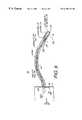
- FIG. 5is a diagrammatic view of a low power radiation treatment system having a flexible probe embodying the present invention.
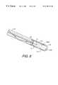
- FIG. 6is a diagrammatic view of a low power radiation source embodying the present invention.
- the present inventionis directed to a miniature, low power radiation producing probe which can be used for diagnostic, therapeutic and palliative treatment of patients.
- the radiation source in accordance with the present inventioncan made smaller than conventional radiation sources.
- the radiation sourcecan be disposed at the distal end of the tip of a flexible (or rigid) tube or catheter which can be inserted into the body. In one embodiment, only a single high voltage wire is necessary for operation.
- the target and the outer surface of the probeare set at the ground potential to reduce the shock hazard of the device.
- FIG. 1Ashows an x-ray apparatus 10 embodying the present invention.
- Apparatus 10includes a housing 12 and an elongated cylindrical probe 14 extending from housing 12 along a reference axis 16 to an x-ray source assembly 19 .
- the probe 14is flexible, as described below, but in some cases may be rigid.
- the housing 12encloses a high voltage power supply 12 A, a battery 12 B and a control system 12 C.
- the x-ray source assembly 19has an electron source (cathode) 22 located in the distal end of the probe 14 .
- Electron source 22may be located in close proximity to a channel electron multiplier (CEM) 23 which receives electrons from the electron source 22 .
- CEMchannel electron multiplier
- An accelerator 24is positioned between the CEM 23 and an x-ray emitting (in response to incident accelerated electrons) target 26 .
- the targetunderlies on x-ray transmissive window 27 .
- Probe 14is integral with the housing 12 and extends toward the target 26 .
- the x-ray emitting tipmay be selectively shielded to control the spatial distribution of x-rays.
- the accelerator 24may be magnetically shielded to prevent external magnetic fields from deflecting the beam away from designed impact points on the target.
- FIG. 1Bshows an x-ray source assembly 19 ′ for generating x-rays embodying the present invention. That source 19 ′ is adapted for placement at the end of a cylindrical element (flexible or rigid). In an alternate form, shown in FIGS. 2A and 2B, an x-ray source 19 ′ is positioned within a compact housing 12 , the latter device is suitable to applying x-radiation body surface tissue.
- the electron beam generator 22may include a thermionic emitter (driven by a low voltage power source or a laser or laser) or a photocathode (irradiated by an LED or laser source) or a field emitter.
- a single high voltage power supply 12 Acan be used to power the electron source (thermionic emitter) 22 , the CEM 23 and accelerator 24 .
- the accelerator 24establishes an acceleration potential difference between the CEM 23 and the target 26 which is at ground potential.
- the beam generation and acceleration componentscan be adapted to establish a thin (e.g. 1 mm or less in diameter) electron beam within the assembly 19 along a nominally straight axis 16 .
- the CEM 23is constructed as is well known and the electron multiplication value is predetermined as function of the intended use of the radiation source.
- a high voltage of 1 Kvoltis connected to input end of the CEM.
- the acceleratoris constructed from a monolithic ceramic material and includes an interior channel formed in the shape of the surface of a cone, although other shapes may be used, for example parabolic.
- the acceleratoris disposed between the CEM 23 and the target 26 along the axis of the electron beam trajectory whereby the distance of the surface from the beam increases as a function of the distance from the CEM 23 .
- the surfaceincludes a semiconductive coating 24 A which ensures that the voltage gradient in the accelerator is smooth and linear and helps to prevent breakdown which occurs when the electrons hit the walls of the accelerator.
- the acceleratoris the type described in commonly owned U.S. patent application Ser. No. 09/211,144 entitled ELECTRON BEAM MULTISTAGE ACCELERATOR, which is incorporated herein by reference.
- the outer cylindrical portion of the x-ray source assembly 19is a hollow evacuated cylinder made of a molybdenum-rhenium, (Mo—Re), molybdenum (Mo) or mu-metal body with an interior diameter of 2 mm, and an exterior diameter of 3 mm.
- beryllium (Be) cap and having a distance from the electron source to the targetis less than 2 mm.
- the target assembly 26includes an emission element consisting of a small beryllium (Be) target element 26 A which is coated on the side exposed to the incident electron beam with a thin film or layer 26 B of a high-Z element, such as tungsten (W), uranium (U) or gold (Au).
- the beryllium target element 26 Ais 0.5 mm thick with the result that 95% of the x-rays generated in directions normal to and toward the substrate 26 A, and having passed through the tungsten target, are then transmitted through the beryllium substrate and outward at the distal end of assembly 19 .
- the target element 26 A shown in FIG. 3Bis in the form of a hemispherical layer, other shaped elements may be used, such as those having disk-like or conical shapes.
- the window element 26 Amay include a multiple layer film 26 B, where the differing layers may have different emission characteristics.
- the first layermay have an emission (vs. energy) peak at a relatively low energy
- the second (underlying) layermay have an emission (vs. energy) peak at a relatively high energy.
- a low energy electron beammay be used to generate x-rays in the first layer (to achieve a first radiation characteristic) and high energy electrons may be used to penetrate through to the underlying layer (to achieve a second radiation characteristic).
- a 0.5 mm wide electron beamis emitted at the cathode and accelerated to 30 keV- through the anode, with 0.1 eV transverse electron energies, and arrives at the target assembly 26 downstream from the anode, with a beam diameter of less than 1 mm at the target assembly 26 .
- X-raysare generated in the target assembly 26 in accordance with preselected beam voltage, current, and target element 26 B composition. The x-rays thus generated pass through the beryllium target substrate 26 A with minimized loss in energy.
- the target substrate 26 Amay be made of carbon or other suitable material which permits x-rays to pass with a minimum loss of energy.
- target substrate 26 AAn optimal material for target substrate 26 A is carbon in its diamond form, since that material is an excellent heat conductor. Using these parameters, the resultant x-rays have sufficient energy to penetrate into soft tissues to a depth of a centimeter or more, the exact depth dependent upon the x-ray energy distribution.
- FIGS. 2A and 2Bis particularly adapted for full implantation into a patient, where the housing 12 a biocompatible outer surface and encloses both a high voltage power supply circuit 12 A for establishing a drive voltage for the beam generator 22 , and an associated battery 12 B for driving that circuit 12 A.
- an associated controller 12 Cestablishes control of the output voltage of the high power supply circuit 12 A, in the manner described below.
- FIGS. 1A and 1Bmay be used in a manner where only the probe 14 and x-ray source assembly 19 are inserted into a patient while the housing 12 remains outside the patient, i.e., a transcutaneous form. In the latter form, some or all of the various elements shown within housing 12 may alternatively be remotely located.
- the apparatus 10may be used with an elongated closed end (or cup-shaped) sheath 34 , as shown in FIG. 3, having a biocompatible outer surface, for example, fabricated of medical grade aliphatic polyurethane, as manufactured under the trademark Tecoflex by Thermedics, Inc., Woburn, Mass.
- the probe 14is first inserted into the sheath 34 .
- the sheath 34 and probe 14are then inserted into the patient through the skin.
- a portmay be inserted through the skin and attached to it, as for example a Dermaport port manufactured by Thermedics Inc., Woburn, Mass.
- the probe 14is then inserted into the port.
- the lining of the sheath or portcan be configured as an x-ray shield by introducing barium sulfate or bismuth trioxide, or other x-ray shielding materials, into the sheath. If necessary, the probe 14 and housing 12 can be secured to the patient's body to prevent any relative motion during the extended time of treatment.
- An exemplary sheath 34is shown in FIG. 3 .
- the main body of the probe 14can be made of a magnetically shielding material such as a mu-metal.
- the probe 14can be made of a non-magnetic metal, preferably having relatively high values for Young's modulus and elastic limit. Examples of such material include molybdenum, rhenium or alloys of these materials.
- the outer cylindrical shell of the accelerator 24can be made of the outer shell metal.
- the inner or outer surface of probe 14can then be coated with a high permeability magnetic alloy such as permalloy (approximately 80% nickel and 20% iron), to provide magnetic shielding.
- a thin sleeve of mu-metalcan be fitted over, or inside of that shell of accelerator 24 .
- the x-ray apparatus 10can then be used in environments in which there are dc and ac magnetic fields due to electrical power, the field of the earth, or other magnetized bodies nominally capable of deflecting the electron beam from the probe axis.
- the power supply 12 A and target assembly 26are preferably enclosed in a capsule to prevent current flow from the x-ray source to the patient.
- the closed housing 12 and probe 14are, thus, encapsulated in a continuous outer shell of appropriate shielding material such as those mentioned previously.
- the high voltage power supply 12 A in each of the illustrated embodimentspreferably satisfies three criteria: 1) small in size; 2) high efficiency to enable the use of battery power; and 3) independently variable x-ray tube voltage and current to enable the unit to be programmed for specific applications.
- a high-frequency, switch-mode power converteris used to meet these requirements.
- the most appropriate topology for generating low power and high voltageis a resonant voltage converter working in conjunction with a high voltage, Cockroft-Walton-type multiplier.
- Low-power dissipation, switch-mode power-supply controller-integrated circuits (IC)are currently available for controlling such topologies with few ancillary components.
- FIGS. 2A and 2Bcan also be adapted for superficial usage, that is for direct placement on the skin of a patient. This form of the invention is particularly useful for x-ray treatment of skin lesions or tumors, or other dermatological applications.
- Apparatus 10 ′generates an electron beam in a channel 40 enclosed within housing 12 , where that channel 40 corresponds to probe 14 .
- the x-ray source assembly 19functions in a manner similar to that described above. With the configuration of FIGS. 2A and 2B, low power x-rays may be directed to a desired skin region of a patient.
- the x-ray emission element of the target assemblyis adapted to be adjacent to or within the region to be irradiated.
- the proximity of the emission element to the targeted region, e.g. the tumoreliminates the need for the high voltages of presently used machines, to achieve satisfactory x-ray penetration through the body wall to the tumor site.
- the low voltagealso concentrates the radiation in the targeted tumor, and limits the damage to surrounding tissue and surface skin at the point of penetration.
- the delivery of 4000 radsas is required after a mastectomy, with a 40 kV, 20 ⁇ A electron beam, may require approximately 1 to 3 hours of radiation.
- the x-ray sourceis, in this preferred embodiment, insertable proximate to, or into, the region-to-be-irradiated risk of incidental radiation exposure to other parts of the patient's body is significantly reduced.
- specificity in treating tumorsmay be achieved by tailoring the target and shield geometry and material at the emission site, for example as disclosed in U.S. Pat. No. 5,369,679, entitled LOW POWER X-RAY SOURCE WITH IMPLANTABLE PROBE FOR TREATMENT, issued Nov. 29, 1994, assigned to the assignee of the present invention.
- This tailoringfacilitates the control of energy and the spatial profile of the x-ray emission to ensure more homogenous distribution of the radiation throughout the targeted tumor.
- FIG. 4is a schematic representation of the x-ray source apparatus 10 shown in FIG. 1 A.
- the housing 12is divided into a first portion 12 ′ and a second portion 12 ′′.
- a rechargeable battery 12 BEnclosed within the first housing portion 12 ′ is a rechargeable battery 12 B, a recharge network 12 D for the battery 12 B, which is adapted for use with an external charger 50 , and a telemetry network 12 E, adapted to be responsive to an external telemetry device 52 to function in the manner described below.
- That portion 12 ′is coupled by cables to the second housing portion 12 ′′.
- the second housing portion 12 ′′includes the high voltage power supply 12 A, controller 12 C and the probe 14 , as well as the electron beam generating element 22 .
- the electron beam generatorincludes a thermionic emitter 22 driven by the power supply 12 A.
- power supply 12 Aheats the thermionic emitter 22 , which in turn generates electrons which are then accelerated toward the anode 24 .
- the anode 24attracts the electrons, but passes them through its central aperture toward the target assembly 26 .
- the controller 12 Ccontrols the power supply 12 A to dynamically adjust the cathode voltage, the electron beam current, and temporal parameters, or to provide pre-selected voltage, beam current, and temporal parameters.
- an alternative electron beam generatorwhich includes a photoemitter 22 irradiated by a light source 56 , such as a diode laser or LED, powered by a driver 55 .
- the lightis focused on the photoemitter 22 by a focusing lens 58 .
- external telemetry device 52 and telemetry network 12 Ecooperate to permit external control (dynamic or predetermined) control over the power supply 12 A and temporal parameters.
- the controller 12 Cmay directly be used to control operation and in that case there is no need for network 12 E.
- FIGS. 5 and 6show a diagrammatic view of radiation treatment apparatus 200 including a flexible probe 214 .
- the apparatus 200includes a high voltage source 218 , a laser (or other optical) source 220 , a probe assembly 214 , and a radiation source assembly 226 .
- the apparatus 200provides the required flexibility, without using strong magnetic fields, by locating electron source components 222 , 223 and accelerator 224 near the target 228 in the distal end of the probe 214 .
- the probe assembly 214couples both the laser source 220 and the high voltage feed 218 to the radiation source assembly 226 .
- the probe assemblyincludes flexible fiber optical cable 202 enclosed in a small-diameter flexible metallic tube 204 .
- the radiation source assembly 226which can be for example 1 to 2 cm in length, extends from the end of the probe assembly 214 and includes a shell which encloses the target 228 .
- the radiation source assembly 226is rigid in nature and generally cylindrical in shape.
- the cylindrical shell enclosing the radiations source assembly 226can be considered to provide a housing for the electron beam source as well as a tubular probe extending from the housing along the electron beam path.
- the inner surface 226 A of the assembly 226is lined with an electrical insulator, while the external surface of the assembly 226 is electrically conductive.
- the radiation source assemblyis hermetically sealed to the end of the probe assembly 214 , and evacuated.
- the entire probe assembly 214is evacuated.
- the terminal end 202 A of the fiber optical cable 202is preferably coated, over at least part of its area, with a semitransparent photoemissive substance such as, Ag—O—Cs, thus forming a photocathode 222 .
- a high voltage conductor 208embedded in the fiber optical cable 202 , conducts electrons to the cathode 222 (if necessary), the electron multiplier 223 and the accelerator 224 from the high voltage source 218 .
- the flexible tube 204couples a ground return from the target 228 to the high voltage source 218 , thereby establishing a high voltage field between the cathode 216 and the target 228 .
- the fiber optical cable 202acts as an insulating dielectric between the high voltage conductor 208 and the grounded flexible tube 204 .
- the fiber optic cable 202can have an annular configuration.
- the light from the laser 220travels down the annular core of the fiber optic cable 202 .
- Claddingcan be provided on each side of the core having an index of refraction so as to reflect the light beam incident on the interface back into the core.
- the grounded flexible metal tube 204can surround the outer cladding.
- the target 228can be for example, beryllium, (Be), coated on one side with a thin film or layer 228 A of a higher atomic number element, such as tungsten (W) or gold (Au).
- Beberyllium,
- a thin film or layer 228 A of a higher atomic number elementsuch as tungsten (W) or gold (Au).
- the small semiconductor laser 220shining down the fiber optical cable 202 activates the transmissive photocathode 222 which generates free electrons 216 .
- the high voltage field between the cathode 222 and target 228accelerates these electrons, thereby forcing them to strike the surface 228 A of target 228 and produce x-rays.
- the 0.4% quantum efficiency of this photocathode 222 for this wavelengthrequires that the laser 220 emits 7.5 mW optical power.
- diode lasersare readily commercially available.
- the photoemissive surface which forms cathode 222can, in fact, be quite small.
- the photoemitter's diameterneed only be approximately 50 ⁇ m.
- One difficult fabrication aspect of this inventionis the fabrication of the photocathode 222 , which for practical substances, with reasonable quantum efficiencies above 10 ⁇ 3 , should be performed in a vacuum.
- This procedurecan be carried out with the fiber optical cable 202 positioned in a bell jar, where for example, an Ag—O—Cs photosurface is fabricated in the conventional manner.
- the optical cable 202can be inserted into the tube 204 .
- the end 202 Bcan be vacuum sealed to the flexible tube 204 .
- the probe 14 or 214along with its associated target 26 , or 228 , can be coated with a biocompatible outer layer, such as titanium nitride on a sublayer of nickel.
- a sheath of, for example, polyurethanecan be fitted over the probe, such as that illustrated in FIG. 3 .
Landscapes
- Health & Medical Sciences (AREA)
- Engineering & Computer Science (AREA)
- Biomedical Technology (AREA)
- Pathology (AREA)
- Nuclear Medicine, Radiotherapy & Molecular Imaging (AREA)
- Radiology & Medical Imaging (AREA)
- Life Sciences & Earth Sciences (AREA)
- Animal Behavior & Ethology (AREA)
- General Health & Medical Sciences (AREA)
- Public Health (AREA)
- Veterinary Medicine (AREA)
- Radiation-Therapy Devices (AREA)
Abstract
Description
Claims (21)
Priority Applications (5)
| Application Number | Priority Date | Filing Date | Title |
|---|---|---|---|
| US09/311,792US6195411B1 (en) | 1999-05-13 | 1999-05-13 | Miniature x-ray source with flexible probe |
| AU48399/00AAU4839900A (en) | 1999-05-13 | 2000-05-11 | Miniature x-ray source and flexible probe |
| PCT/US2000/012920WO2000070645A1 (en) | 1999-05-13 | 2000-05-11 | Miniature x-ray source and flexible probe |
| EP00930607AEP1208582A4 (en) | 1999-05-13 | 2000-05-11 | Miniature x-ray source and flexible probe |
| US09/748,590US6320932B2 (en) | 1999-05-13 | 2000-12-22 | Miniature radiation source with flexible probe and laser driven thermionic emitter |
Applications Claiming Priority (1)
| Application Number | Priority Date | Filing Date | Title |
|---|---|---|---|
| US09/311,792US6195411B1 (en) | 1999-05-13 | 1999-05-13 | Miniature x-ray source with flexible probe |
Related Child Applications (1)
| Application Number | Title | Priority Date | Filing Date |
|---|---|---|---|
| US09/748,590DivisionUS6320932B2 (en) | 1999-05-13 | 2000-12-22 | Miniature radiation source with flexible probe and laser driven thermionic emitter |
Publications (1)
| Publication Number | Publication Date |
|---|---|
| US6195411B1true US6195411B1 (en) | 2001-02-27 |
Family
ID=23208494
Family Applications (2)
| Application Number | Title | Priority Date | Filing Date |
|---|---|---|---|
| US09/311,792Expired - LifetimeUS6195411B1 (en) | 1999-05-13 | 1999-05-13 | Miniature x-ray source with flexible probe |
| US09/748,590Expired - LifetimeUS6320932B2 (en) | 1999-05-13 | 2000-12-22 | Miniature radiation source with flexible probe and laser driven thermionic emitter |
Family Applications After (1)
| Application Number | Title | Priority Date | Filing Date |
|---|---|---|---|
| US09/748,590Expired - LifetimeUS6320932B2 (en) | 1999-05-13 | 2000-12-22 | Miniature radiation source with flexible probe and laser driven thermionic emitter |
Country Status (4)
| Country | Link |
|---|---|
| US (2) | US6195411B1 (en) |
| EP (1) | EP1208582A4 (en) |
| AU (1) | AU4839900A (en) |
| WO (1) | WO2000070645A1 (en) |
Cited By (40)
| Publication number | Priority date | Publication date | Assignee | Title |
|---|---|---|---|---|
| US6320935B1 (en)* | 2000-02-28 | 2001-11-20 | X-Technologies, Ltd. | Dosimeter for a miniature energy transducer for emitting X-ray radiation |
| US6407492B1 (en)* | 1997-01-02 | 2002-06-18 | Advanced Electron Beams, Inc. | Electron beam accelerator |
| US20020115902A1 (en)* | 2001-02-22 | 2002-08-22 | Dejuan Eugene | Beta radiotherapy emitting surgical device and methods of use thereof |
| US6450407B1 (en) | 1998-04-17 | 2002-09-17 | Viztec, Inc. | Chip card rebate system |
| WO2002103743A1 (en)* | 2001-06-19 | 2002-12-27 | Photoelectron Corporation | X-RAY SOURCE FOR MATERIALS ANALYSIS SYSTEMs |
| WO2003030596A1 (en)* | 2001-10-01 | 2003-04-10 | Extreme Devices Incorporated | Compact multispectral x-ray source |
| US20030139788A1 (en)* | 2002-01-18 | 2003-07-24 | Eggers Philip E. | System method and apparatus for localized heating of tissue |
| US6658086B2 (en)* | 2001-06-19 | 2003-12-02 | Carl Zeiss | Optically driven therapeutic radiation source with voltage gradient control |
| US6661875B2 (en) | 2002-05-09 | 2003-12-09 | Spire Corporation | Catheter tip x-ray source |
| US20040091081A1 (en)* | 2002-11-06 | 2004-05-13 | Frank Udo Emil | Microfocus X-ray tube |
| US6738451B2 (en) | 2001-03-20 | 2004-05-18 | Advanced Electron Beams, Inc. | X-ray irradiation apparatus |
| US20040122494A1 (en)* | 2002-01-18 | 2004-06-24 | Eggers Philip E. | System, method and apparatus evaluating tissue temperature |
| US20040165699A1 (en)* | 2003-02-21 | 2004-08-26 | Rusch Thomas W. | Anode assembly for an x-ray tube |
| US20040174956A1 (en)* | 2003-03-03 | 2004-09-09 | Varian Medical Systems, Inc. | Apparatus and method for shaping high voltage potentials on an insulator |
| US6811562B1 (en)* | 2000-07-31 | 2004-11-02 | Epicor, Inc. | Procedures for photodynamic cardiac ablation therapy and devices for those procedures |
| US20050031077A1 (en)* | 2001-03-20 | 2005-02-10 | Advanced Electron Beams, Inc. | X-ray irradiation apparatus |
| US20050123097A1 (en)* | 2002-04-08 | 2005-06-09 | Nanodynamics, Inc. | High quantum energy efficiency X-ray tube and targets |
| US20050226378A1 (en)* | 2004-04-06 | 2005-10-13 | Duke University | Devices and methods for targeting interior cancers with ionizing radiation |
| US20050232395A1 (en)* | 2004-04-19 | 2005-10-20 | Varian Medical Systems Technologies, Inc. | High voltage connector for x-ray tube |
| US20050277802A1 (en)* | 2004-02-12 | 2005-12-15 | Larsen Charles E | Method and apparatus for intraocular brachytherapy |
| US6993394B2 (en) | 2002-01-18 | 2006-01-31 | Calfacion Corporation | System method and apparatus for localized heating of tissue |
| US20060049359A1 (en)* | 2003-04-01 | 2006-03-09 | Cabot Microelectronics Corporation | Decontamination and sterilization system using large area x-ray source |
| US20060111605A1 (en)* | 2004-02-12 | 2006-05-25 | Larsen Charles E | Methods and apparatus for intraocular brachytherapy |
| US20070118010A1 (en)* | 2005-02-11 | 2007-05-24 | Hillstead Richard A | Methods and apparatus for intraocular brachytherapy |
| US20090299446A1 (en)* | 2008-05-28 | 2009-12-03 | Lovoi Paul A | Durable fine wire lead for therapeutic electrostimulation and sensing |
| US20100331941A1 (en)* | 2008-05-28 | 2010-12-30 | Walsh Robert G | Implantable fine wire lead for electrostimulation and sensing |
| US20110220408A1 (en)* | 2009-02-23 | 2011-09-15 | Walsh Robert G | Electrode and connector attachments for a cylindrical glass fiber wire lead |
| US20120027181A1 (en)* | 2009-04-07 | 2012-02-02 | Adtech Sensing Research Inc. | X-Ray Generator and Composite Device Using the Same and X-Ray Generating Method |
| US8353812B2 (en) | 2008-06-04 | 2013-01-15 | Neovista, Inc. | Handheld radiation delivery system |
| US20140079188A1 (en)* | 2012-09-14 | 2014-03-20 | The Board Of Trustees Of The Leland Stanford Junior University | Photo Emitter X-Ray Source Array (PeXSA) |
| US8692117B2 (en) | 2008-05-28 | 2014-04-08 | Cardia Access, Inc. | Durable fine wire electrical conductor suitable for extreme environment applications |
| US20140146947A1 (en)* | 2012-11-28 | 2014-05-29 | Vanderbilt University | Channeling x-rays |
| US9025598B1 (en) | 2012-03-22 | 2015-05-05 | Nuax, Inc. | Cable/guidewire/interconnects communication apparatus and methods |
| US9193313B2 (en) | 2012-03-22 | 2015-11-24 | Nuax, Inc. | Methods and apparatuses involving flexible cable/guidewire/interconnects |
| US9242100B2 (en) | 2012-08-07 | 2016-01-26 | Nuax, Inc. | Optical fiber-fine wire lead for electrostimulation and sensing |
| US9513443B2 (en) | 2008-05-28 | 2016-12-06 | John Lawrence Erb | Optical fiber-fine wire conductor and connectors |
| US20190178821A1 (en)* | 2017-12-11 | 2019-06-13 | Rapiscan Systems, Inc. | X-Ray Tomography Inspection Systems and Methods |
| CN112074234A (en)* | 2018-05-21 | 2020-12-11 | 深圳帧观德芯科技有限公司 | device for imaging the prostate |
| US11778717B2 (en) | 2020-06-30 | 2023-10-03 | VEC Imaging GmbH & Co. KG | X-ray source with multiple grids |
| US12230468B2 (en) | 2022-06-30 | 2025-02-18 | Varex Imaging Corporation | X-ray system with field emitters and arc protection |
Families Citing this family (16)
| Publication number | Priority date | Publication date | Assignee | Title |
|---|---|---|---|---|
| US6537195B2 (en) | 2001-05-07 | 2003-03-25 | Xoft, Microtube, Inc. | Combination x-ray radiation and drug delivery devices and methods for inhibiting hyperplasia |
| US7018371B2 (en) | 2001-05-07 | 2006-03-28 | Xoft, Inc. | Combination ionizing radiation and radiosensitizer delivery devices and methods for inhibiting hyperplasia |
| JP4268037B2 (en)* | 2001-06-19 | 2009-05-27 | フォトエレクトロン コーポレイション | Optically driven therapeutic radiation source |
| US6847164B2 (en)* | 2002-12-10 | 2005-01-25 | Applied Matrials, Inc. | Current-stabilizing illumination of photocathode electron beam source |
| JP2006524881A (en)* | 2003-01-16 | 2006-11-02 | カールツァイスシュティフトゥング、ディー/ビー/エイ カールツァイス、オーバーコーへン、ジャーマニー | Thermally tuned field emission cathode and beam current measurement techniques |
| DE102005022120B4 (en)* | 2005-05-12 | 2009-04-09 | Siemens Ag | Catheter, catheter device and diagnostic imaging device |
| CN101689408A (en)* | 2007-04-04 | 2010-03-31 | 加利福尼亚大学董事会 | Laser activated micro accelerator platform |
| EP2188826B1 (en)* | 2007-09-04 | 2013-02-20 | Thermo Scientific Portable Analytical Instruments Inc. | X-ray tube with enhanced small spot cathode and methods for manufacture thereof |
| GB2446505A (en)* | 2008-02-05 | 2008-08-13 | Gen Electric | X-ray generation using a secondary emission electron source |
| US8663210B2 (en) | 2009-05-13 | 2014-03-04 | Novian Health, Inc. | Methods and apparatus for performing interstitial laser therapy and interstitial brachytherapy |
| JP6140983B2 (en)* | 2012-11-15 | 2017-06-07 | キヤノン株式会社 | Transmission target, X-ray generation target, X-ray generation tube, X-ray X-ray generation apparatus, and X-ray X-ray imaging apparatus |
| US20140264065A1 (en)* | 2013-03-15 | 2014-09-18 | Varian Medical Systems, Inc. | Energy degrader for radiation therapy system |
| EP3496127A1 (en)* | 2017-12-07 | 2019-06-12 | Koninklijke Philips N.V. | Cathode assembly component for x-ray imaging |
| CN108087836B (en)* | 2018-01-18 | 2023-11-03 | 华域视觉科技(上海)有限公司 | Flexible mounting structure of laser fiber |
| RU180983U1 (en)* | 2018-03-23 | 2018-07-03 | Общество с ограниченной ответственностью "Синтез НПФ" | X-ray radiator |
| RU2703588C1 (en)* | 2018-12-25 | 2019-10-21 | Общество с ограниченной ответственностью "Синтез НПФ" | X-ray emitter |
Citations (40)
| Publication number | Priority date | Publication date | Assignee | Title |
|---|---|---|---|---|
| US1981583A (en) | 1929-10-17 | 1934-11-20 | Invex Corp | Method of preserving fruits, vegetables, etc. |
| US2748293A (en) | 1951-09-08 | 1956-05-29 | Hartford Nat Bank & Trust Co | Irradiation applicator for X-ray therapy |
| US3714486A (en) | 1970-10-07 | 1973-01-30 | Crary J Mc | Field emission x-ray tube |
| US3752990A (en) | 1970-06-22 | 1973-08-14 | H Fischer | X-ray device having an anode tube with filtering means thereon |
| US3920999A (en) | 1972-12-05 | 1975-11-18 | Strahlen Und Umweltforachung M | X-Ray source |
| US4104531A (en) | 1976-10-04 | 1978-08-01 | Thoro-Ray Inc. | Electron beam target carrier with ceramic window for dental or medical X-ray use |
| US4104532A (en) | 1976-04-01 | 1978-08-01 | Thoro-Ray Inc. | Dental and medical X-ray apparatus |
| US4109154A (en) | 1977-03-18 | 1978-08-22 | Applied Radiation | X-ray beam compensation |
| US4117334A (en) | 1977-04-11 | 1978-09-26 | Magnaflux Corporation | Portable x-ray unit with self-contained voltage supply |
| US4157475A (en) | 1977-10-21 | 1979-06-05 | Applied Radiation Corporation | Electron accelerator comprising a target exposed to the electron beam |
| US4205251A (en) | 1976-10-04 | 1980-05-27 | U.S. Philips Corporation | X-ray tube for the examination of fine structures |
| US4344181A (en) | 1978-06-21 | 1982-08-10 | Baecklund Nils J | Method and apparatus for measuring the content or quantity of a given element by means of X-ray radiation |
| US4517472A (en) | 1983-07-06 | 1985-05-14 | The United States Of America As Represented By The Administrator Of The National Aeronautics And Space Administration | High voltage power supply |
| US4563769A (en) | 1981-12-29 | 1986-01-07 | Andrex Radiation Products A/S | X-Ray generator device |
| DE3543591A1 (en) | 1984-12-11 | 1986-06-12 | Hamamatsu Photonics K.K., Hamamatsu, Shizuoka | X-ray tube |
| US4606061A (en) | 1983-12-28 | 1986-08-12 | Tokyo Shibaura Denki Kabushiki Kaisha | Light controlled x-ray scanner |
| US4608997A (en) | 1985-01-25 | 1986-09-02 | Becton, Dickinson And Company | Blood collection assembly |
| US4646338A (en) | 1983-08-01 | 1987-02-24 | Kevex Corporation | Modular portable X-ray source with integral generator |
| US4662368A (en) | 1983-06-13 | 1987-05-05 | Trimedyne Laser Systems, Inc. | Localized heat applying medical device |
| US4692938A (en) | 1984-12-11 | 1987-09-08 | Hamamatsu Photonics Kabushiki Kaisha | X-ray shadow graph device |
| US4694480A (en) | 1985-07-30 | 1987-09-15 | Kevex Corporation | Hand held precision X-ray source |
| US4714825A (en) | 1984-12-11 | 1987-12-22 | Hamamatsu Photonics Kabushiki Kaisha | System for calibrating the time axis of an X-ray streak tube |
| US4773413A (en) | 1983-06-13 | 1988-09-27 | Trimedyne Laser Systems, Inc. | Localized heat applying medical device |
| US4789997A (en) | 1986-07-15 | 1988-12-06 | Andrex Radiation Products As | Circuit arrangement for producing high voltages |
| US4821305A (en) | 1986-03-25 | 1989-04-11 | Varian Associates, Inc. | Photoelectric X-ray tube |
| US4852567A (en) | 1988-01-21 | 1989-08-01 | C. R. Bard, Inc. | Laser tipped catheter |
| US4856036A (en) | 1986-05-15 | 1989-08-08 | Xi Tech Inc. | Method for production of fluoroscopic and radiographic x-ray images and hand held diagnostic apparatus incorporating the same |
| US4921327A (en) | 1989-05-24 | 1990-05-01 | Zito Richard R | Method of transmitting an ionizing radiation |
| US4924485A (en) | 1987-09-22 | 1990-05-08 | Hoeberling Robert F | Portable radiography system using a relativistic electron beam |
| US5042058A (en) | 1989-03-22 | 1991-08-20 | University Of California | Ultrashort time-resolved x-ray source |
| JPH03251263A (en) | 1990-03-01 | 1991-11-08 | Nec Corp | Laser device for medical treatment |
| US5090043A (en) | 1990-11-21 | 1992-02-18 | Parker Micro-Tubes, Inc. | X-ray micro-tube and method of use in radiation oncology |
| US5116344A (en) | 1987-04-27 | 1992-05-26 | Elekta Instrument Ab | Apparatus for marking an operating site |
| US5116345A (en) | 1990-11-28 | 1992-05-26 | Ohio Medical Instrument Co., Inc. | Stereotactically implanting an intracranial device |
| US5147353A (en) | 1990-03-23 | 1992-09-15 | Myriadlase, Inc. | Medical method for applying high energy light and heat for gynecological sterilization procedures |
| US5153900A (en) | 1990-09-05 | 1992-10-06 | Photoelectron Corporation | Miniaturized low power x-ray source |
| WO1992017243A2 (en) | 1991-04-05 | 1992-10-15 | Indigo Medical, Incorporated | Apparatus using a laser lucent needle |
| US5165093A (en) | 1992-03-23 | 1992-11-17 | The Titan Corporation | Interstitial X-ray needle |
| US5576549A (en)* | 1994-07-20 | 1996-11-19 | Siemens Aktiengesellschaft | Electron generating assembly for an x-ray tube having a cathode and having an electrode system for accelerating the electrons emanating from the cathode |
| US5729583A (en) | 1995-09-29 | 1998-03-17 | The United States Of America As Represented By The Secretary Of Commerce | Miniature x-ray source |
Family Cites Families (4)
| Publication number | Priority date | Publication date | Assignee | Title |
|---|---|---|---|---|
| JPH03285239A (en)* | 1990-03-30 | 1991-12-16 | Shimadzu Corp | X-ray tube equipment |
| US5422926A (en)* | 1990-09-05 | 1995-06-06 | Photoelectron Corporation | X-ray source with shaped radiation pattern |
| US5768337A (en)* | 1996-07-30 | 1998-06-16 | Varian Associates, Inc. | Photoelectric X-ray tube with gain |
| US6111932A (en)* | 1998-12-14 | 2000-08-29 | Photoelectron Corporation | Electron beam multistage accelerator |
- 1999
- 1999-05-13USUS09/311,792patent/US6195411B1/ennot_activeExpired - Lifetime
- 2000
- 2000-05-11AUAU48399/00Apatent/AU4839900A/ennot_activeAbandoned
- 2000-05-11EPEP00930607Apatent/EP1208582A4/ennot_activeWithdrawn
- 2000-05-11WOPCT/US2000/012920patent/WO2000070645A1/enactiveApplication Filing
- 2000-12-22USUS09/748,590patent/US6320932B2/ennot_activeExpired - Lifetime
Patent Citations (40)
| Publication number | Priority date | Publication date | Assignee | Title |
|---|---|---|---|---|
| US1981583A (en) | 1929-10-17 | 1934-11-20 | Invex Corp | Method of preserving fruits, vegetables, etc. |
| US2748293A (en) | 1951-09-08 | 1956-05-29 | Hartford Nat Bank & Trust Co | Irradiation applicator for X-ray therapy |
| US3752990A (en) | 1970-06-22 | 1973-08-14 | H Fischer | X-ray device having an anode tube with filtering means thereon |
| US3714486A (en) | 1970-10-07 | 1973-01-30 | Crary J Mc | Field emission x-ray tube |
| US3920999A (en) | 1972-12-05 | 1975-11-18 | Strahlen Und Umweltforachung M | X-Ray source |
| US4104532A (en) | 1976-04-01 | 1978-08-01 | Thoro-Ray Inc. | Dental and medical X-ray apparatus |
| US4205251A (en) | 1976-10-04 | 1980-05-27 | U.S. Philips Corporation | X-ray tube for the examination of fine structures |
| US4104531A (en) | 1976-10-04 | 1978-08-01 | Thoro-Ray Inc. | Electron beam target carrier with ceramic window for dental or medical X-ray use |
| US4109154A (en) | 1977-03-18 | 1978-08-22 | Applied Radiation | X-ray beam compensation |
| US4117334A (en) | 1977-04-11 | 1978-09-26 | Magnaflux Corporation | Portable x-ray unit with self-contained voltage supply |
| US4157475A (en) | 1977-10-21 | 1979-06-05 | Applied Radiation Corporation | Electron accelerator comprising a target exposed to the electron beam |
| US4344181A (en) | 1978-06-21 | 1982-08-10 | Baecklund Nils J | Method and apparatus for measuring the content or quantity of a given element by means of X-ray radiation |
| US4563769A (en) | 1981-12-29 | 1986-01-07 | Andrex Radiation Products A/S | X-Ray generator device |
| US4773413A (en) | 1983-06-13 | 1988-09-27 | Trimedyne Laser Systems, Inc. | Localized heat applying medical device |
| US4662368A (en) | 1983-06-13 | 1987-05-05 | Trimedyne Laser Systems, Inc. | Localized heat applying medical device |
| US4517472A (en) | 1983-07-06 | 1985-05-14 | The United States Of America As Represented By The Administrator Of The National Aeronautics And Space Administration | High voltage power supply |
| US4646338A (en) | 1983-08-01 | 1987-02-24 | Kevex Corporation | Modular portable X-ray source with integral generator |
| US4606061A (en) | 1983-12-28 | 1986-08-12 | Tokyo Shibaura Denki Kabushiki Kaisha | Light controlled x-ray scanner |
| DE3543591A1 (en) | 1984-12-11 | 1986-06-12 | Hamamatsu Photonics K.K., Hamamatsu, Shizuoka | X-ray tube |
| US4692938A (en) | 1984-12-11 | 1987-09-08 | Hamamatsu Photonics Kabushiki Kaisha | X-ray shadow graph device |
| US4714825A (en) | 1984-12-11 | 1987-12-22 | Hamamatsu Photonics Kabushiki Kaisha | System for calibrating the time axis of an X-ray streak tube |
| US4608997A (en) | 1985-01-25 | 1986-09-02 | Becton, Dickinson And Company | Blood collection assembly |
| US4694480A (en) | 1985-07-30 | 1987-09-15 | Kevex Corporation | Hand held precision X-ray source |
| US4821305A (en) | 1986-03-25 | 1989-04-11 | Varian Associates, Inc. | Photoelectric X-ray tube |
| US4856036A (en) | 1986-05-15 | 1989-08-08 | Xi Tech Inc. | Method for production of fluoroscopic and radiographic x-ray images and hand held diagnostic apparatus incorporating the same |
| US4789997A (en) | 1986-07-15 | 1988-12-06 | Andrex Radiation Products As | Circuit arrangement for producing high voltages |
| US5116344A (en) | 1987-04-27 | 1992-05-26 | Elekta Instrument Ab | Apparatus for marking an operating site |
| US4924485A (en) | 1987-09-22 | 1990-05-08 | Hoeberling Robert F | Portable radiography system using a relativistic electron beam |
| US4852567A (en) | 1988-01-21 | 1989-08-01 | C. R. Bard, Inc. | Laser tipped catheter |
| US5042058A (en) | 1989-03-22 | 1991-08-20 | University Of California | Ultrashort time-resolved x-ray source |
| US4921327A (en) | 1989-05-24 | 1990-05-01 | Zito Richard R | Method of transmitting an ionizing radiation |
| JPH03251263A (en) | 1990-03-01 | 1991-11-08 | Nec Corp | Laser device for medical treatment |
| US5147353A (en) | 1990-03-23 | 1992-09-15 | Myriadlase, Inc. | Medical method for applying high energy light and heat for gynecological sterilization procedures |
| US5153900A (en) | 1990-09-05 | 1992-10-06 | Photoelectron Corporation | Miniaturized low power x-ray source |
| US5090043A (en) | 1990-11-21 | 1992-02-18 | Parker Micro-Tubes, Inc. | X-ray micro-tube and method of use in radiation oncology |
| US5116345A (en) | 1990-11-28 | 1992-05-26 | Ohio Medical Instrument Co., Inc. | Stereotactically implanting an intracranial device |
| WO1992017243A2 (en) | 1991-04-05 | 1992-10-15 | Indigo Medical, Incorporated | Apparatus using a laser lucent needle |
| US5165093A (en) | 1992-03-23 | 1992-11-17 | The Titan Corporation | Interstitial X-ray needle |
| US5576549A (en)* | 1994-07-20 | 1996-11-19 | Siemens Aktiengesellschaft | Electron generating assembly for an x-ray tube having a cathode and having an electrode system for accelerating the electrons emanating from the cathode |
| US5729583A (en) | 1995-09-29 | 1998-03-17 | The United States Of America As Represented By The Secretary Of Commerce | Miniature x-ray source |
Cited By (78)
| Publication number | Priority date | Publication date | Assignee | Title |
|---|---|---|---|---|
| US6407492B1 (en)* | 1997-01-02 | 2002-06-18 | Advanced Electron Beams, Inc. | Electron beam accelerator |
| US6450407B1 (en) | 1998-04-17 | 2002-09-17 | Viztec, Inc. | Chip card rebate system |
| US6320935B1 (en)* | 2000-02-28 | 2001-11-20 | X-Technologies, Ltd. | Dosimeter for a miniature energy transducer for emitting X-ray radiation |
| US6811562B1 (en)* | 2000-07-31 | 2004-11-02 | Epicor, Inc. | Procedures for photodynamic cardiac ablation therapy and devices for those procedures |
| US20020115902A1 (en)* | 2001-02-22 | 2002-08-22 | Dejuan Eugene | Beta radiotherapy emitting surgical device and methods of use thereof |
| US7220225B2 (en) | 2001-02-22 | 2007-05-22 | Retinalabs, Inc. | Intraocular radiotherapy treatment |
| US7276019B2 (en) | 2001-02-22 | 2007-10-02 | Retinalabs, Inc. | Ophthalmic treatment apparatus |
| US20070265485A1 (en)* | 2001-02-22 | 2007-11-15 | Dejuan Eugene Jr | Beta radiotherapy emitting surgical device and methods of use thereof |
| US20060142629A1 (en)* | 2001-02-22 | 2006-06-29 | Dejuan Eugene Jr | Intraocular radiotherapy treatment for macular degeneration |
| US7223225B2 (en) | 2001-02-22 | 2007-05-29 | Retinalabs, Inc. | Intraocular radiotherapy treatment for macular degeneration |
| US8100818B2 (en) | 2001-02-22 | 2012-01-24 | TDH Partners, Inc. | Beta radiotherapy emitting surgical device and methods of use thereof |
| US20050177019A1 (en)* | 2001-02-22 | 2005-08-11 | Dejuan Eugene Jr. | Ophthalmic treatment apparatus |
| US6875165B2 (en) | 2001-02-22 | 2005-04-05 | Retinalabs, Inc. | Method of radiation delivery to the eye |
| US7324630B2 (en) | 2001-03-20 | 2008-01-29 | Advanced Electron Beams, Inc. | X-ray irradiation apparatus |
| US6738451B2 (en) | 2001-03-20 | 2004-05-18 | Advanced Electron Beams, Inc. | X-ray irradiation apparatus |
| US20050031077A1 (en)* | 2001-03-20 | 2005-02-10 | Advanced Electron Beams, Inc. | X-ray irradiation apparatus |
| US20070071167A1 (en)* | 2001-03-20 | 2007-03-29 | Tzvi Avnery | X-ray irradiation apparatus |
| US7133493B2 (en) | 2001-03-20 | 2006-11-07 | Advanced Electron Beams, Inc. | X-ray irradiation apparatus |
| WO2002103743A1 (en)* | 2001-06-19 | 2002-12-27 | Photoelectron Corporation | X-RAY SOURCE FOR MATERIALS ANALYSIS SYSTEMs |
| US6658086B2 (en)* | 2001-06-19 | 2003-12-02 | Carl Zeiss | Optically driven therapeutic radiation source with voltage gradient control |
| US20060233307A1 (en)* | 2001-06-19 | 2006-10-19 | Mark Dinsmore | X-ray source for materials analysis systems |
| US7526068B2 (en) | 2001-06-19 | 2009-04-28 | Carl Zeiss Ag | X-ray source for materials analysis systems |
| WO2003030596A1 (en)* | 2001-10-01 | 2003-04-10 | Extreme Devices Incorporated | Compact multispectral x-ray source |
| US6993394B2 (en) | 2002-01-18 | 2006-01-31 | Calfacion Corporation | System method and apparatus for localized heating of tissue |
| US7048756B2 (en) | 2002-01-18 | 2006-05-23 | Apasara Medical Corporation | System, method and apparatus for evaluating tissue temperature |
| US6850804B2 (en) | 2002-01-18 | 2005-02-01 | Calfacior Corporation | System method and apparatus for localized heating of tissue |
| US20030139788A1 (en)* | 2002-01-18 | 2003-07-24 | Eggers Philip E. | System method and apparatus for localized heating of tissue |
| US20040122494A1 (en)* | 2002-01-18 | 2004-06-24 | Eggers Philip E. | System, method and apparatus evaluating tissue temperature |
| US7180981B2 (en) | 2002-04-08 | 2007-02-20 | Nanodynamics-88, Inc. | High quantum energy efficiency X-ray tube and targets |
| US20050123097A1 (en)* | 2002-04-08 | 2005-06-09 | Nanodynamics, Inc. | High quantum energy efficiency X-ray tube and targets |
| US6661875B2 (en) | 2002-05-09 | 2003-12-09 | Spire Corporation | Catheter tip x-ray source |
| US7050543B2 (en)* | 2002-11-06 | 2006-05-23 | Feinfocus Röntgen-Systeme GmbH | Microfocus X-ray tube |
| US20040091081A1 (en)* | 2002-11-06 | 2004-05-13 | Frank Udo Emil | Microfocus X-ray tube |
| US7158612B2 (en)* | 2003-02-21 | 2007-01-02 | Xoft, Inc. | Anode assembly for an x-ray tube |
| US20040165699A1 (en)* | 2003-02-21 | 2004-08-26 | Rusch Thomas W. | Anode assembly for an x-ray tube |
| US20050100659A1 (en)* | 2003-03-03 | 2005-05-12 | Chidester Charles L. | Apparatus and method for shaping high voltage potentials on an insulator |
| WO2004079375A3 (en)* | 2003-03-03 | 2005-04-07 | Varian Med Sys Tech Inc | Apparatus and method for shaping high voltage potentials on an insulator |
| US20040174956A1 (en)* | 2003-03-03 | 2004-09-09 | Varian Medical Systems, Inc. | Apparatus and method for shaping high voltage potentials on an insulator |
| US6819741B2 (en)* | 2003-03-03 | 2004-11-16 | Varian Medical Systems Inc. | Apparatus and method for shaping high voltage potentials on an insulator |
| US20060049359A1 (en)* | 2003-04-01 | 2006-03-09 | Cabot Microelectronics Corporation | Decontamination and sterilization system using large area x-ray source |
| US7447298B2 (en) | 2003-04-01 | 2008-11-04 | Cabot Microelectronics Corporation | Decontamination and sterilization system using large area x-ray source |
| US20070055089A1 (en)* | 2004-02-12 | 2007-03-08 | Larsen Charles E | Methods and apparatus for intraocular brachytherapy |
| US7563222B2 (en) | 2004-02-12 | 2009-07-21 | Neovista, Inc. | Methods and apparatus for intraocular brachytherapy |
| US7951060B2 (en) | 2004-02-12 | 2011-05-31 | Neovista, Inc. | Methods and apparatus for intraocular brachytherapy |
| US20100268013A1 (en)* | 2004-02-12 | 2010-10-21 | Larsen Charles E | Methods and apparatus for intraocular brachytherapy |
| US20060111605A1 (en)* | 2004-02-12 | 2006-05-25 | Larsen Charles E | Methods and apparatus for intraocular brachytherapy |
| US20050277802A1 (en)* | 2004-02-12 | 2005-12-15 | Larsen Charles E | Method and apparatus for intraocular brachytherapy |
| US7803102B2 (en) | 2004-02-12 | 2010-09-28 | Neovista, Inc. | Methods and apparatus for intraocular brachytherapy |
| US20110004045A1 (en)* | 2004-02-12 | 2011-01-06 | Larsen Charles E | Methods And Apparatus for Intraocular Brachytherapy |
| US8365721B2 (en) | 2004-02-12 | 2013-02-05 | Neovista Inc. | Methods and apparatus for intraocular brachytherapy |
| US7744520B2 (en) | 2004-02-12 | 2010-06-29 | Neovista, Inc. | Method and apparatus for intraocular brachytherapy |
| US20050226378A1 (en)* | 2004-04-06 | 2005-10-13 | Duke University | Devices and methods for targeting interior cancers with ionizing radiation |
| US7200203B2 (en) | 2004-04-06 | 2007-04-03 | Duke University | Devices and methods for targeting interior cancers with ionizing radiation |
| US20050232395A1 (en)* | 2004-04-19 | 2005-10-20 | Varian Medical Systems Technologies, Inc. | High voltage connector for x-ray tube |
| US7142639B2 (en) | 2004-04-19 | 2006-11-28 | Varian Medical Systems Technologies, Inc. | High voltage connector for x-ray tube |
| US8292795B2 (en) | 2005-02-11 | 2012-10-23 | Neovista, Inc. | Methods and apparatus for intraocular brachytherapy |
| US7803103B2 (en) | 2005-02-11 | 2010-09-28 | Neovista Inc. | Methods and apparatus for intraocular brachytherapy |
| US20070118010A1 (en)* | 2005-02-11 | 2007-05-24 | Hillstead Richard A | Methods and apparatus for intraocular brachytherapy |
| US8692117B2 (en) | 2008-05-28 | 2014-04-08 | Cardia Access, Inc. | Durable fine wire electrical conductor suitable for extreme environment applications |
| US9513443B2 (en) | 2008-05-28 | 2016-12-06 | John Lawrence Erb | Optical fiber-fine wire conductor and connectors |
| US9478327B2 (en) | 2008-05-28 | 2016-10-25 | Nuax, Inc. | Durable fine wire electrical conductor suitable for extreme environment applications |
| US20100331941A1 (en)* | 2008-05-28 | 2010-12-30 | Walsh Robert G | Implantable fine wire lead for electrostimulation and sensing |
| US20090299446A1 (en)* | 2008-05-28 | 2009-12-03 | Lovoi Paul A | Durable fine wire lead for therapeutic electrostimulation and sensing |
| US8353812B2 (en) | 2008-06-04 | 2013-01-15 | Neovista, Inc. | Handheld radiation delivery system |
| US20110220408A1 (en)* | 2009-02-23 | 2011-09-15 | Walsh Robert G | Electrode and connector attachments for a cylindrical glass fiber wire lead |
| US20120027181A1 (en)* | 2009-04-07 | 2012-02-02 | Adtech Sensing Research Inc. | X-Ray Generator and Composite Device Using the Same and X-Ray Generating Method |
| US8917814B2 (en)* | 2009-04-07 | 2014-12-23 | Mikio Takai | X-ray generator and composite device using the same and X-ray generating method |
| US9025598B1 (en) | 2012-03-22 | 2015-05-05 | Nuax, Inc. | Cable/guidewire/interconnects communication apparatus and methods |
| US9193313B2 (en) | 2012-03-22 | 2015-11-24 | Nuax, Inc. | Methods and apparatuses involving flexible cable/guidewire/interconnects |
| US9242100B2 (en) | 2012-08-07 | 2016-01-26 | Nuax, Inc. | Optical fiber-fine wire lead for electrostimulation and sensing |
| US20140079188A1 (en)* | 2012-09-14 | 2014-03-20 | The Board Of Trustees Of The Leland Stanford Junior University | Photo Emitter X-Ray Source Array (PeXSA) |
| US9520260B2 (en)* | 2012-09-14 | 2016-12-13 | The Board Of Trustees Of The Leland Stanford Junior University | Photo emitter X-ray source array (PeXSA) |
| US20140146947A1 (en)* | 2012-11-28 | 2014-05-29 | Vanderbilt University | Channeling x-rays |
| US20190178821A1 (en)* | 2017-12-11 | 2019-06-13 | Rapiscan Systems, Inc. | X-Ray Tomography Inspection Systems and Methods |
| CN111448481A (en)* | 2017-12-11 | 2020-07-24 | 拉皮斯坎系统股份有限公司 | X-ray tomography inspection system and method |
| CN112074234A (en)* | 2018-05-21 | 2020-12-11 | 深圳帧观德芯科技有限公司 | device for imaging the prostate |
| US11778717B2 (en) | 2020-06-30 | 2023-10-03 | VEC Imaging GmbH & Co. KG | X-ray source with multiple grids |
| US12230468B2 (en) | 2022-06-30 | 2025-02-18 | Varex Imaging Corporation | X-ray system with field emitters and arc protection |
Also Published As
| Publication number | Publication date |
|---|---|
| US6320932B2 (en) | 2001-11-20 |
| AU4839900A (en) | 2000-12-05 |
| EP1208582A1 (en) | 2002-05-29 |
| EP1208582A4 (en) | 2003-01-29 |
| WO2000070645A8 (en) | 2001-03-29 |
| WO2000070645A1 (en) | 2000-11-23 |
| US20010016027A1 (en) | 2001-08-23 |
Similar Documents
| Publication | Publication Date | Title |
|---|---|---|
| US6195411B1 (en) | Miniature x-ray source with flexible probe | |
| EP0770258B1 (en) | X-ray apparatus for applying a predetermined flux to an interior surface of a body cavity | |
| JP3110463B2 (en) | X-ray source using shape radiation pattern | |
| US5153900A (en) | Miniaturized low power x-ray source | |
| US5528652A (en) | Method for treating brain tumors | |
| US5369679A (en) | Low power x-ray source with implantable probe for treatment of brain tumors | |
| US6556651B1 (en) | Array of miniature radiation sources | |
| US6728335B1 (en) | Controller for array of miniature radiation sources | |
| US6480568B1 (en) | Optically driven therapeutic radiation source | |
| US6914960B2 (en) | Miniature x-ray emitter having independent current and voltage control |
Legal Events
| Date | Code | Title | Description |
|---|---|---|---|
| AS | Assignment | Owner name:PHOTOELECTRON CORPORATION, MASSACHUSETTS Free format text:ASSIGNMENT OF ASSIGNORS INTEREST;ASSIGNOR:DINSMORE, MARK;REEL/FRAME:011438/0583 Effective date:20010102 | |
| STCF | Information on status: patent grant | Free format text:PATENTED CASE | |
| AS | Assignment | Owner name:PYC CORPORATION, GREECE Free format text:SECURITY AGREEMENT;ASSIGNOR:PHOTOELECTRON CORPORATION;REEL/FRAME:013705/0362 Effective date:20030121 | |
| AS | Assignment | Owner name:CARL-ZEISS-STIFTUNG DOING BUSINESS AS CARL ZEISS, Free format text:ASSET PURCHASE AGREEMENT;ASSIGNOR:PHOTOELECTRON CORPORATION;REEL/FRAME:014981/0591 Effective date:20030604 | |
| FPAY | Fee payment | Year of fee payment:4 | |
| AS | Assignment | Owner name:CARL ZEISS AG, GERMANY Free format text:CHANGE OF NAME;ASSIGNOR:CARL-ZEISS-STIFTUING DOING BUSINESS AS ZEISS, CARL;REEL/FRAME:017555/0001 Effective date:20040420 | |
| FEPP | Fee payment procedure | Free format text:PAYOR NUMBER ASSIGNED (ORIGINAL EVENT CODE: ASPN); ENTITY STATUS OF PATENT OWNER: LARGE ENTITY | |
| FEPP | Fee payment procedure | Free format text:PAT HOLDER NO LONGER CLAIMS SMALL ENTITY STATUS, ENTITY STATUS SET TO UNDISCOUNTED (ORIGINAL EVENT CODE: STOL); ENTITY STATUS OF PATENT OWNER: LARGE ENTITY | |
| SULP | Surcharge for late payment | ||
| FPAY | Fee payment | Year of fee payment:8 | |
| FPAY | Fee payment | Year of fee payment:12 |