US6195356B1 - Switcher for spanning subnetworks - Google Patents
Switcher for spanning subnetworksDownload PDFInfo
- Publication number
- US6195356B1 US6195356B1US08/991,614US99161497AUS6195356B1US 6195356 B1US6195356 B1US 6195356B1US 99161497 AUS99161497 AUS 99161497AUS 6195356 B1US6195356 B1US 6195356B1
- Authority
- US
- United States
- Prior art keywords
- station
- address
- subnet
- frame
- data packets
- Prior art date
- Legal status (The legal status is an assumption and is not a legal conclusion. Google has not performed a legal analysis and makes no representation as to the accuracy of the status listed.)
- Expired - Lifetime
Links
- 238000000034methodMethods0.000claimsabstractdescription24
- 230000004044responseEffects0.000claimsabstractdescription10
- 238000004590computer programMethods0.000claimsabstractdescription7
- 238000013507mappingMethods0.000claimsdescription5
- 230000008569processEffects0.000abstractdescription11
- 238000004891communicationMethods0.000abstractdescription8
- 230000005540biological transmissionEffects0.000description5
- 230000007246mechanismEffects0.000description3
- 238000010586diagramMethods0.000description2
- 230000006870functionEffects0.000description2
- 230000008878couplingEffects0.000description1
- 238000010168coupling processMethods0.000description1
- 238000005859coupling reactionMethods0.000description1
- 238000013500data storageMethods0.000description1
- 230000007423decreaseEffects0.000description1
- 230000001934delayEffects0.000description1
- 239000000835fiberSubstances0.000description1
- 238000012986modificationMethods0.000description1
- 230000004048modificationEffects0.000description1
- 230000008520organizationEffects0.000description1
- 230000011664signalingEffects0.000description1
Images

Classifications
- H—ELECTRICITY
- H04—ELECTRIC COMMUNICATION TECHNIQUE
- H04L—TRANSMISSION OF DIGITAL INFORMATION, e.g. TELEGRAPHIC COMMUNICATION
- H04L12/00—Data switching networks
- H04L12/28—Data switching networks characterised by path configuration, e.g. LAN [Local Area Networks] or WAN [Wide Area Networks]
- H04L12/46—Interconnection of networks
- H04L12/4604—LAN interconnection over a backbone network, e.g. Internet, Frame Relay
- H04L12/462—LAN interconnection over a bridge based backbone
Definitions
- This inventionrelates to network packet transmission, and more particularly to a method and apparatus for switching packets between subnetworks.
- Data transmission systemsenable a number of nodes or “stations” to communicate with each other at high speeds at a distance.
- a stationmay be any one of a number of different types of devices, including computers and printers.
- the combination of a data transmission system and a number of stations coupled to the data transmission systemis commonly known as a network.
- Networkstransmit data and control information by addressed protocol data units, known as “frames” or “packets” depending on context.
- Stationstypically include hardware and software for coupling the station to a data transmission system, generally using a common communication protocol. Examples of networks include Fiber Distributed Data Interface (FDDI), Token Ring, and EthernetTM local area networks (LANs) and the InternetTM wide area network (WAN).
- FDDIFiber Distributed Data Interface
- LANsToken Ring
- WANwide area network
- OSIOpen Systems Interconnect
- the Physical layer(layer 1 ) defines cable, connector and signaling specifications.
- the Data Link layer(layer 2 ) is generally broken into two sub-layers: Logical Link Control (LLC) on the upper half, and Medium Access Control (MAC) on the lower half, which deals with getting protocol data units on and off the physical layer.
- LLCLogical Link Control
- MACMedium Access Control
- the Network layer(layer 3 ) makes certain that protocol data units sent from one station to another station actually gets to the desired destination in a reasonable period of time. Routing and flow control of protocol data units are performed in layer 3 .
- layer 2 protocol data unitsare called frames, while layer 3 protocol data units are known as packets.
- protocol data unitsare often referred to generically as packets.
- networkssuch as FDDI, Token Ring and Ethernet LANs
- FDDIFrequency Division Duplex
- Token RingEthernet LANs
- network “switches”are often added to networks to link smaller segments of a network, thereby reducing the number of stations per network segment and improving performance.
- a Layer 2 switchconnects separate segments of a network
- a form of frame switchingtakes place.
- a networkcan be split into subnetworks (subnets) connected by routers.
- subnetssubnets
- a Layer 3 routerconnects subnets, a form of packet switching takes place.
- Switchesperform very fast bridging between small network segments with minimal network congestion.
- a layer 2 switchoperates on frames at the MAC layer.
- Frames on a networkare encoded using a definition referred to as a MAC format.
- MAC formatOn an IEEE 802 network (which includes Ethernet), frames are built around a MAC format which utilizes 6-byte station addresses.
- a frame sent from one station to another station on the same networkincludes two of these 6-byte addresses, a destination station address and a source station address. These 6-byte addresses are usually referred to as MAC addresses and every station has a unique 6-byte address. The two 6-byte addresses are contained in the MAC header portion of every frame sent on the network.
- a layer 2 switchuses the two 6-byte MAC addresses to move frames between input and output ports of the switch. As frames arrive in a layer 2 switch, the destination address is extracted from the arriving frame. The switch looks up the destination address in a forwarding table and determines to which port on the switch the current frame should be sent. This process is called forwarding. The source address is extracted and added to the forwarding table if not already present. This process is known as “learning”. Through this process of learning and forwarding, a layer 2 switch moves frames between its ports.
- a switchwhen a switch receives a frame, it compares the frame's destination address with addresses in the forwarding table.
- the switchdiscards the frame; all stations on that LAN have already received this frame.
- the switchforwards the frame to that LAN segment.
- the switchforwards the frame to all coupled network segments except the one that received the frame. This is called flooding.
- a routeris a network device which operates on packets at a higher layer, typically layer 3 .
- Layer 3 protocolssuch as the Internet Protocol (IP), utilize their own addressing mechanism which is quite different than the 6-byte MAC addresses used in layer 2 . These addresses in IP version 4 “IPv4” are 4-bytes in length.
- IPv4IP version 4
- IP subnetsIn order for data packets to be sent between stations on different Layer 3 addressed subnets (“IP subnets”), a router is used.
- the routeraccepts packets from an input port connected to one IP subnet when the packets are addressed at layer 2 to the router. Such packets are destined for stations on another IP subnet connected to an output port of the router.
- the destination for the packetis defined by the layer 3 address contained in the packet.
- the routerlooks up the layer 3 address in an internal routing table, determines the destination layer 2 address that should receive the packet (which may be another router), and substitutes this new layer 2 address for the old layer 2 address within the packet.
- the packetis then sent out the appropriate destination port on the router to the destination IP subnet.
- a routerBecause routing involves changes to the data packet as the router moves a packet from input port to output port, a router introduces delays into the movement of packets in the network. This delay is referred to as latency. For example, a typical router might be able to examine and route about 1,000 packets per second.
- Layer 2 switchesdo not modify the packet and thus the latency surrounding switching is significantly smaller than the latency for routing. For example, a typical switch may be able to switch frames at a rate 10 times or more faster than a typical router. However, layer 2 switches do not examine the layer 3 address, and thus cannot switch packets between IP subnets.
- the inventorshave determined that it would be useful to have an apparatus and method that would allow switching of frames between IP subnets based upon layer 3 addresses.
- the present inventionprovides such an apparatus and method.
- the inventionincludes an apparatus and method that allows a layer 2 “spanning” switch to switch data packets between IP subnets based upon layer 3 packet addresses.
- the inventionallows designated stations attached to different IP subnets to communicate with each other without the need for a router between the subnets.
- the inventionthus provides high speed point-to-point connectivity between the different subnets.
- the inventionmay be used in conjunction with a conventional router to permit general low-speed layer 3 inter-subnet communication through the router, and high-speed point-to-point layer 2 inter-subnet communication through the spanning switch.
- the inventioncan be implemented within a layer 2 switch to allow the switch to move data packets between attached subnets. By using layer 2 switching techniques, the invention permits high speed movement of data packets between IP subnets.
- the inventionmay be implemented in hardware or software, or a combination of both.
- the inventionuses the fact that hosts on an IP network keep track of where to send data packets on different subnets in a table.
- ICMPInternet Control Message Protocol
- a “spanning” switch on a subnetcan offer itself as a destination for data packets crossing to another subnet.
- ICMPInternet Control Message Protocol
- a layer 2 switchis taught how to forward data packets between two stations on different subnets. The switch can then teach the two stations how to communicate via the layer 2 switch.
- the layer 2 switchis allocated a “virtual” IP address on each subnet for each station that wants to be involved in cross-subnet communications.
- one aspect of the inventionincludes a method for switching data packets between subnets of a network having frame and packet addresses, comprising the steps of: configuring a switching device coupled to each subnet to have a virtual packet address on each subnet associated with a packet address of a station on another subnet; providing a designated station on each subnet with the virtual packet address on such subnet and with an address for the associated station on another subnet; providing a frame address of a destination station on another subnet in response to requests from a designated station on a subnet relating to transmitting data packets to the destination station; switching data packets from such designated station to the destination station through the switching device in response to the presence of the frame address in such data packets.
- the inventionincludes related apparatus and computer programs.
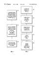
- FIG. 1is a block diagram of a preferred embodiment of the invention.
- FIG. 2is a flow chart showing the setup process in accordance with the preferred embodiment of the invention.
- FIG. 3is a flow chart showing the operational process in accordance with the preferred embodiment of the invention.
- FIG. 1is a block diagram of a preferred embodiment of the invention.
- a set of stations A 1 . . . A Nare coupled to a IP subnet A, and a set of a set of stations B 1 . . . B N are coupled to an similar subnet B.
- Each station on a subnet A, Bis physically and logically connected to a “spanning” switch 10 but is logically disconnected from stations on the other subnet B, A.
- this configurationwould mean that traffic could not be forwarded between the subnets A, B as is required for proper operation of the Internet Protocol (IP).
- IPInternet Protocol
- a router instead of a switchwould be required to route data packets using layer 3 addresses.
- a “virtual” IP address on one subnetis defined and can be used by a designated station on that subnet to send data to a designated station on another subnet.
- station A 1can send a data packet addressed to a virtual address on subnet A but with an ultimate destination for station B 1 on subnet B.
- the inventionprovides a mechanism whereby the data packet is mapped to station B 1 .
- FIG. 2is a flow chart showing the setup process in accordance with the preferred embodiment of the invention.
- a network administratorprovides to the spanning switch 10 the following configuration information (STEP 20):
- IP address of a designated station from each subnet A, B(e.g., stations A 1 and B 1 ), such as IP A1 and IP B1 .
- the IP address informationmay be entered by means of a console keyboard associated with the spanning switch 10 , or by means of remote entry program executing from a station within one of the subnets A, B.
- the spanning switch 10itself has its own IP address on each subnet A, B, for communication directly with the switch. There may be more than two subnets coupled through the spanning switch 10 .
- a suitable spanning switch 10may be, for example, a Millennium 4000TM switch from XLNT Designs, Inc. of California, suitably programmed in accordance with the present invention.
- the virtual addressesmay be automatically assigned to the spanning switch 10 by means, for example, of a control protocol such as the Dynamic Host Control Protocol (DHCP).
- DHCPDynamic Host Control Protocol
- the spanning switch 10then initializes each designed station by transmitting the virtual address information corresponding to each subnet to the designated station on that subnet, along with an associated station address (STEP 22). For example, the IP VA1 address and associated station address IP B1 of station B 1 is transmitted to the IP A1 address of station A 1 , and the IP VB1 address and associated station address IP A1 of station A, is transmitted to the IP B1 address of station B 1 .
- the spanning switch 10sends the initialization information by means of a standard ICMP “Redirect Packet”. This data packet essentially associates a station with an IP address.
- the virtual address information in each messageinforms the receiving station of the IP address that station should use for sending data packets to a station on the other subnet.
- the address a station on subnet A usesis a subnet A IP address
- the address a station on subnet B usesis a subnet B IP address.
- the spanning switch 10also builds an IP/MAC table that maps virtual IP addresses (layer 3 ) on each subnet to the MAC address (layer 2 ) of the corresponding station on the other subnet (STEP 24). For example, the spanning switch 10 would build a table that maps IP VA1 to the MAC address of station B 1 , and IP VB1 to the MAC address of station A 1 .
- the MAC addressesmay be determined by the spanning switch 10 by using the well-known “Ping” program to find the IP address IP A1 , IP B1 of each designated station.
- the spanning switch 10also builds a table mapping MAC addresses to port addresses, in known fashion.
- FIG. 3is a flow chart showing the operational process in accordance with the preferred embodiment of the invention.
- station A 1 on subnet Awants to send a data packet to station B 1 on subnet B
- station A 1looks up the IP address for station B 1 in an internal table, in known fashion (STEP 30). Because station A 1 was “told” by the spanning switch 10 that the IP address of station B 1 was IP VA1 (an address on subnet A), station A 1 will retrieve the IP VA1 address from the lookup table. Station A, then uses the IP VA1 address as a destination address for a standard Address Resolution Protocol (ARP) command packet broadcast on subnet A to determine the MAC address corresponding to the virtual IP address IP VA1 (STEP 32).
- ARPAddress Resolution Protocol
- the spanning switch 10receives the broadcast ARP command packet. Since the spanning switch 10 is aware that it is controlling the virtual IP address IP VA1 , the spanning switch 10 looks up that IP address in an internal IP/MAC table and retrieves the corresponding MAC address, MAC B , of the actual destination, station B 1 , previously associated with the received virtual IP address. The spanning switch 10 then broadcasts back on subnet A an ARP Reply packet with the MAC B address of station B 1 (STEP 34).
- station A 1sends data packets addressed to station B 1 using the MAC B address of station B 1 as the MAC Destination Address in the layer 2 frame header (STEP 36).
- the spanning switch 10now can treat such data packets at the layer 2 level and forward the data packets from station A 1 on subnet A to station B 1 on subnet B.
- the spanning switch 10switches each data packet with a destination address of MAC B to a corresponding Port B , as determined by the MAC/Port Table of the spanning switch 10 (STEP 38). Since each data packet from station A 1 carries a source MAC address for station A 1 , station B 1 can easily address replies through the spanning switch 10 to station A 1 using the MAC address.
- the inventionallows designated stations on logically disjoint IP subnets to communicate at high speed by means of layer 2 forwarding mechanisms.
- the inventionallows data packets to traverse IP subnets without the intervention of a layer 3 router and their inherent latency requirements.
- the inventionmay be used in conjunction with a conventional router to permit general low-speed layer 3 inter-subnet communication through the router, and high-speed point-to-point layer 2 inter-subnet communication through the spanning switch. This may be useful, for example, when a few users require a significant amount of bandwidth across subnets, and the per-packet latency overhead of routers would impair the performance of a subnet for all users.
- the inventionwould provide a fast point-to-point connection for the high-bandwidth users, while permitting other uses to send cross-subnet data packets by means of a conventional router.
- the inventioncan be implemented within a layer 2 switch to allow the switch to move data packets between attached subnets.
- the inventionpermits high speed movement of data packets between IP subnets.
- the inventionmay be implemented in hardware or software, or a combination of both. However, preferably, the invention is implemented in computer programs executing on programmable computers each comprising at least one processor, at least one data storage system (including volatile and non-volatile memory and/or storage elements), at least one input device, and at least one output device. Program code is applied to input data to perform the functions described herein and generate output information. The output information is applied to one or more output devices, in known fashion.
- Each programis preferably implemented in a high level procedural or object oriented programming language to communicate with a computer system.
- the programscan be implemented in assembly or machine language, if desired.
- the languagemay be a compiled or interpreted language.
- Each such computer programis preferably stored on a storage media or device (e.g., ROM, CDROM, or magnetic diskette) readable by a general or special purpose programmable computer, for configuring and operating the computer when the storage media or device is read by the computer to perform the procedures described herein.
- a storage media or devicee.g., ROM, CDROM, or magnetic diskette
- the inventive systemmay also be considered to be implemented as a computer-readable storage medium, configured with a computer program, where the storage medium so configured causes a computer to operate in a specific and predefined manner to perform the functions described herein.
- IP/MAC tablefor the spanning switch 10 during the setup process (STEP 24)
- the tablecould instead be built at a later time, such as when a station first attempts to send a data packet across to another subnet (for example, during STEP 34).
- some of the process stepsmay be done in other orders.
- STEP 24may be done before STEP 22.
- IP subnetshas been used, the invention may be used with any Layer 3 addressing protocol. Accordingly, other embodiments are within the scope of the following claims.
Landscapes
- Engineering & Computer Science (AREA)
- Computer Networks & Wireless Communication (AREA)
- Signal Processing (AREA)
- Data Exchanges In Wide-Area Networks (AREA)
Abstract
Description
| Packet Layout |
| Layer 2 (MAC) Header | Layer 3 (IP) Header |
| MAC | MAC | IP | IP | Packe |
| Destination Ad- | Source Ad- | Source Ad- | Destination | t |
| dress | dress | dress | Address | Data |
Claims (6)
Priority Applications (1)
| Application Number | Priority Date | Filing Date | Title |
|---|---|---|---|
| US08/991,614US6195356B1 (en) | 1997-12-17 | 1997-12-17 | Switcher for spanning subnetworks |
Applications Claiming Priority (1)
| Application Number | Priority Date | Filing Date | Title |
|---|---|---|---|
| US08/991,614US6195356B1 (en) | 1997-12-17 | 1997-12-17 | Switcher for spanning subnetworks |
Publications (1)
| Publication Number | Publication Date |
|---|---|
| US6195356B1true US6195356B1 (en) | 2001-02-27 |
Family
ID=25537391
Family Applications (1)
| Application Number | Title | Priority Date | Filing Date |
|---|---|---|---|
| US08/991,614Expired - LifetimeUS6195356B1 (en) | 1997-12-17 | 1997-12-17 | Switcher for spanning subnetworks |
Country Status (1)
| Country | Link |
|---|---|
| US (1) | US6195356B1 (en) |
Cited By (35)
| Publication number | Priority date | Publication date | Assignee | Title |
|---|---|---|---|---|
| WO2002061599A1 (en)* | 2001-01-25 | 2002-08-08 | Crescent Networks, Inc. | Extension of address resolution protocol (arp) for internet protocol (ip) virtual networks |
| US6457079B1 (en)* | 1999-03-03 | 2002-09-24 | Kobe Steel, Ltd. | Communication apparatus with means for allocating alternate designation information to each function unit, and communication system with said two communication apparatuses |
| US20020186698A1 (en)* | 2001-06-12 | 2002-12-12 | Glen Ceniza | System to map remote lan hosts to local IP addresses |
| US20030118035A1 (en)* | 2001-12-21 | 2003-06-26 | Shantnu Sharma | System and method for reduced frame flooding |
| US20030179750A1 (en)* | 2002-03-15 | 2003-09-25 | Hasty William V. | System and method for auto-configuration and discovery of IP to MAC address mapping and gateway presence in wireless peer-to-peer ad-hoc routing networks |
| US20030200341A1 (en)* | 1999-12-30 | 2003-10-23 | Nortel Networks Corporation, A Canadian Corporation | Port switch |
| US6765914B1 (en)* | 2000-04-07 | 2004-07-20 | 3Com Corporation | Generic switch architecture to support flexible subnets across layer-3 devices |
| US6785738B1 (en)* | 1999-12-23 | 2004-08-31 | Cisco Technology, Inc. | ARP packet to preserve canonical form of addresses |
| US20040177158A1 (en)* | 2003-03-07 | 2004-09-09 | Bauch David James | Network address translation techniques for selective network traffic diversion |
| US6792471B2 (en)* | 1997-07-24 | 2004-09-14 | Fujitsu Limited | Process and apparatus for speeding up layer 2 and layer 3 routing by determining layer 2 reach ability by determining whether layer 2 subnetworks are identical |
| US6807176B1 (en)* | 2000-07-13 | 2004-10-19 | Advanced Micro Devices, Inc. | Arrangement for switching data packets in a network switch based on subnet identifier |
| US20050038907A1 (en)* | 2003-08-14 | 2005-02-17 | Roeder Michael T. | Routing cache management with route fragmentation |
| US6862286B1 (en)* | 2000-05-08 | 2005-03-01 | 3Com Corporation | Tracking dynamic addresses on a network |
| WO2004081715A3 (en)* | 2003-03-07 | 2005-06-30 | Hyperspace Communications Inc | Network address translation techniques for selective network traffic diversion |
| US6996067B1 (en)* | 1999-12-07 | 2006-02-07 | Verizon Services Corp. | Apparatus for and method of providing and measuring data throughput to and from a packet data network |
| US20060087989A1 (en)* | 2004-10-22 | 2006-04-27 | Cisco Technology, Inc., A Corporation Of California | Network device architecture for consolidating input/output and reducing latency |
| US20060101140A1 (en)* | 2004-10-22 | 2006-05-11 | Cisco Technology, Inc. | Ethernet extension for the data center |
| US20060098589A1 (en)* | 2004-10-22 | 2006-05-11 | Cisco Technology, Inc. | Forwarding table reduction and multipath network forwarding |
| US20060153192A1 (en)* | 2005-01-13 | 2006-07-13 | International Business Machines Corporation | Network host isolation tool |
| US20060251078A1 (en)* | 2005-04-12 | 2006-11-09 | Samsung Electronics Co., Ltd. | Message transmission method and device in mixture of private network and public network |
| US20060251067A1 (en)* | 2004-10-22 | 2006-11-09 | Cisco Technology, Inc., A Corporation Of California | Fibre channel over ethernet |
| US20070081454A1 (en)* | 2005-10-11 | 2007-04-12 | Cisco Technology, Inc. A Corporation Of California | Methods and devices for backward congestion notification |
| US20070143464A1 (en)* | 2005-12-21 | 2007-06-21 | Canon Kabushiki Kaisha | Data processing apparatus, data processing method, and computer program |
| US20080186968A1 (en)* | 2007-02-02 | 2008-08-07 | Cisco Technology, Inc. | Triple-tier anycast addressing |
| US20080250496A1 (en)* | 2003-10-07 | 2008-10-09 | Daisuke Namihira | Frame Relay Device |
| US20090034540A1 (en)* | 2007-08-02 | 2009-02-05 | Thales Avionics, Inc. | System and method for streaming video on demand (vod) streams over a local network |
| US20090052326A1 (en)* | 2007-08-21 | 2009-02-26 | Cisco Technology, Inc., A Corporation Of California | Backward congestion notification |
| US20090252038A1 (en)* | 2004-10-22 | 2009-10-08 | Cisco Technology, Inc. | Fibre channel over ethernet |
| US7756027B1 (en)* | 2007-06-13 | 2010-07-13 | Juniper Networks, Inc. | Automatic configuration of virtual network switches |
| KR101064473B1 (en)* | 2004-09-23 | 2011-09-15 | 주식회사 케이티 | How to establish link connection information between switch devices in network management system |
| US8149710B2 (en) | 2007-07-05 | 2012-04-03 | Cisco Technology, Inc. | Flexible and hierarchical dynamic buffer allocation |
| US20150039762A1 (en)* | 2012-04-23 | 2015-02-05 | Tencent Technology (Shenzhen) Company Limited | Method and system for accessing network service |
| US20170041222A1 (en)* | 2015-08-07 | 2017-02-09 | Cisco Technology, Inc. | Virtual Expansion of Network Fabric Edge for Multihoming of Layer-2 Switches and Hosts |
| CN114745403A (en)* | 2022-03-31 | 2022-07-12 | 西门子(中国)有限公司 | Industrial network communication system and industrial network communication method |
| CN115665043A (en)* | 2022-09-09 | 2023-01-31 | 中国联合网络通信集团有限公司 | Data message forwarding method, VTEP, device, medium and system |
Citations (4)
| Publication number | Priority date | Publication date | Assignee | Title |
|---|---|---|---|---|
| US5384766A (en)* | 1992-09-21 | 1995-01-24 | Fujitsu Limited | LAN management system in electronic switching apparatus |
| US5583862A (en)* | 1995-03-28 | 1996-12-10 | Bay Networks, Inc. | Method and apparatus for routing for virtual networks |
| US5732071A (en)* | 1993-12-29 | 1998-03-24 | Kabushiki Kaisha Toshiba | ATM bridge device and ATM bridging scheme for realizing efficient ATM bridge interconnection |
| US5790541A (en)* | 1996-04-01 | 1998-08-04 | Motorola, Inc. | Apparatus, method, system and system method for distributed routing in a multipoint communication system |
- 1997
- 1997-12-17USUS08/991,614patent/US6195356B1/ennot_activeExpired - Lifetime
Patent Citations (4)
| Publication number | Priority date | Publication date | Assignee | Title |
|---|---|---|---|---|
| US5384766A (en)* | 1992-09-21 | 1995-01-24 | Fujitsu Limited | LAN management system in electronic switching apparatus |
| US5732071A (en)* | 1993-12-29 | 1998-03-24 | Kabushiki Kaisha Toshiba | ATM bridge device and ATM bridging scheme for realizing efficient ATM bridge interconnection |
| US5583862A (en)* | 1995-03-28 | 1996-12-10 | Bay Networks, Inc. | Method and apparatus for routing for virtual networks |
| US5790541A (en)* | 1996-04-01 | 1998-08-04 | Motorola, Inc. | Apparatus, method, system and system method for distributed routing in a multipoint communication system |
Cited By (70)
| Publication number | Priority date | Publication date | Assignee | Title |
|---|---|---|---|---|
| US6792471B2 (en)* | 1997-07-24 | 2004-09-14 | Fujitsu Limited | Process and apparatus for speeding up layer 2 and layer 3 routing by determining layer 2 reach ability by determining whether layer 2 subnetworks are identical |
| US6457079B1 (en)* | 1999-03-03 | 2002-09-24 | Kobe Steel, Ltd. | Communication apparatus with means for allocating alternate designation information to each function unit, and communication system with said two communication apparatuses |
| US6996067B1 (en)* | 1999-12-07 | 2006-02-07 | Verizon Services Corp. | Apparatus for and method of providing and measuring data throughput to and from a packet data network |
| US6785738B1 (en)* | 1999-12-23 | 2004-08-31 | Cisco Technology, Inc. | ARP packet to preserve canonical form of addresses |
| US8539111B2 (en)* | 1999-12-30 | 2013-09-17 | Avaya Inc. | Port switch |
| US20030200341A1 (en)* | 1999-12-30 | 2003-10-23 | Nortel Networks Corporation, A Canadian Corporation | Port switch |
| US6765914B1 (en)* | 2000-04-07 | 2004-07-20 | 3Com Corporation | Generic switch architecture to support flexible subnets across layer-3 devices |
| US6862286B1 (en)* | 2000-05-08 | 2005-03-01 | 3Com Corporation | Tracking dynamic addresses on a network |
| US6807176B1 (en)* | 2000-07-13 | 2004-10-19 | Advanced Micro Devices, Inc. | Arrangement for switching data packets in a network switch based on subnet identifier |
| WO2002061599A1 (en)* | 2001-01-25 | 2002-08-08 | Crescent Networks, Inc. | Extension of address resolution protocol (arp) for internet protocol (ip) virtual networks |
| US7260648B2 (en)* | 2001-01-25 | 2007-08-21 | Ericsson, Inc. | Extension of address resolution protocol (ARP) for internet protocol (IP) virtual networks |
| US20020138628A1 (en)* | 2001-01-25 | 2002-09-26 | Crescent Networks, Inc. | Extension of address resolution protocol (ARP) for internet protocol (IP) virtual networks |
| US20020186698A1 (en)* | 2001-06-12 | 2002-12-12 | Glen Ceniza | System to map remote lan hosts to local IP addresses |
| US6999418B2 (en) | 2001-12-21 | 2006-02-14 | Fujitsu Limited | System and method for reduced frame flooding |
| US20030118035A1 (en)* | 2001-12-21 | 2003-06-26 | Shantnu Sharma | System and method for reduced frame flooding |
| US20030179750A1 (en)* | 2002-03-15 | 2003-09-25 | Hasty William V. | System and method for auto-configuration and discovery of IP to MAC address mapping and gateway presence in wireless peer-to-peer ad-hoc routing networks |
| US6728232B2 (en)* | 2002-03-15 | 2004-04-27 | Meshnetworks, Inc. | System and method for auto-configuration and discovery of IP to MAC address mapping and gateway presence in wireless peer-to-peer ad-hoc routing networks |
| WO2004081715A3 (en)* | 2003-03-07 | 2005-06-30 | Hyperspace Communications Inc | Network address translation techniques for selective network traffic diversion |
| US20040177158A1 (en)* | 2003-03-07 | 2004-09-09 | Bauch David James | Network address translation techniques for selective network traffic diversion |
| US7260599B2 (en) | 2003-03-07 | 2007-08-21 | Hyperspace Communications, Inc. | Supporting the exchange of data by distributed applications |
| US20050038907A1 (en)* | 2003-08-14 | 2005-02-17 | Roeder Michael T. | Routing cache management with route fragmentation |
| US7487255B2 (en)* | 2003-08-14 | 2009-02-03 | Hewlett-Packard Development Company, L.P. | Routing cache management with route fragmentation |
| US20080250496A1 (en)* | 2003-10-07 | 2008-10-09 | Daisuke Namihira | Frame Relay Device |
| KR101064473B1 (en)* | 2004-09-23 | 2011-09-15 | 주식회사 케이티 | How to establish link connection information between switch devices in network management system |
| US8532099B2 (en) | 2004-10-22 | 2013-09-10 | Cisco Technology, Inc. | Forwarding table reduction and multipath network forwarding |
| US20110007741A1 (en)* | 2004-10-22 | 2011-01-13 | Cisco Technology, Inc. | Forwarding table reduction and multipath network forwarding |
| US8565231B2 (en) | 2004-10-22 | 2013-10-22 | Cisco Technology, Inc. | Ethernet extension for the data center |
| US20060251067A1 (en)* | 2004-10-22 | 2006-11-09 | Cisco Technology, Inc., A Corporation Of California | Fibre channel over ethernet |
| US20060087989A1 (en)* | 2004-10-22 | 2006-04-27 | Cisco Technology, Inc., A Corporation Of California | Network device architecture for consolidating input/output and reducing latency |
| US20060101140A1 (en)* | 2004-10-22 | 2006-05-11 | Cisco Technology, Inc. | Ethernet extension for the data center |
| US8238347B2 (en) | 2004-10-22 | 2012-08-07 | Cisco Technology, Inc. | Fibre channel over ethernet |
| US8160094B2 (en) | 2004-10-22 | 2012-04-17 | Cisco Technology, Inc. | Fibre channel over ethernet |
| US8842694B2 (en) | 2004-10-22 | 2014-09-23 | Cisco Technology, Inc. | Fibre Channel over Ethernet |
| US9246834B2 (en) | 2004-10-22 | 2016-01-26 | Cisco Technology, Inc. | Fibre channel over ethernet |
| US20090252038A1 (en)* | 2004-10-22 | 2009-10-08 | Cisco Technology, Inc. | Fibre channel over ethernet |
| US20060098589A1 (en)* | 2004-10-22 | 2006-05-11 | Cisco Technology, Inc. | Forwarding table reduction and multipath network forwarding |
| US7969971B2 (en) | 2004-10-22 | 2011-06-28 | Cisco Technology, Inc. | Ethernet extension for the data center |
| US7801125B2 (en) | 2004-10-22 | 2010-09-21 | Cisco Technology, Inc. | Forwarding table reduction and multipath network forwarding |
| US7830793B2 (en) | 2004-10-22 | 2010-11-09 | Cisco Technology, Inc. | Network device architecture for consolidating input/output and reducing latency |
| US20060153192A1 (en)* | 2005-01-13 | 2006-07-13 | International Business Machines Corporation | Network host isolation tool |
| US7463593B2 (en) | 2005-01-13 | 2008-12-09 | International Business Machines Corporation | Network host isolation tool |
| US20060251078A1 (en)* | 2005-04-12 | 2006-11-09 | Samsung Electronics Co., Ltd. | Message transmission method and device in mixture of private network and public network |
| US7701876B2 (en)* | 2005-04-12 | 2010-04-20 | Samsung Electronics Co., Ltd. | Message transmission method and device in mixture of private network and public network |
| US20070081454A1 (en)* | 2005-10-11 | 2007-04-12 | Cisco Technology, Inc. A Corporation Of California | Methods and devices for backward congestion notification |
| US8792352B2 (en) | 2005-10-11 | 2014-07-29 | Cisco Technology, Inc. | Methods and devices for backward congestion notification |
| US7961621B2 (en) | 2005-10-11 | 2011-06-14 | Cisco Technology, Inc. | Methods and devices for backward congestion notification |
| US20070143464A1 (en)* | 2005-12-21 | 2007-06-21 | Canon Kabushiki Kaisha | Data processing apparatus, data processing method, and computer program |
| US8566426B2 (en)* | 2005-12-21 | 2013-10-22 | Canon Kabushiki Kaisha | Data processing apparatus, data processing method, and computer program |
| US8259720B2 (en)* | 2007-02-02 | 2012-09-04 | Cisco Technology, Inc. | Triple-tier anycast addressing |
| US20080186968A1 (en)* | 2007-02-02 | 2008-08-07 | Cisco Technology, Inc. | Triple-tier anycast addressing |
| US8743738B2 (en) | 2007-02-02 | 2014-06-03 | Cisco Technology, Inc. | Triple-tier anycast addressing |
| US20100278076A1 (en)* | 2007-06-13 | 2010-11-04 | Juniper Networks, Inc. | Automatic configuration of virtual network switches |
| US9929911B1 (en)* | 2007-06-13 | 2018-03-27 | Juniper Networks, Inc. | Automatic configuration of virtual network switches |
| US8018891B2 (en) | 2007-06-13 | 2011-09-13 | Juniper Networks, Inc. | Automatic configuration of virtual network switches |
| US7756027B1 (en)* | 2007-06-13 | 2010-07-13 | Juniper Networks, Inc. | Automatic configuration of virtual network switches |
| US9172609B1 (en) | 2007-06-13 | 2015-10-27 | Juniper Networks, Inc. | Automatic configuration of virtual network switches |
| US8705353B1 (en) | 2007-06-13 | 2014-04-22 | Juniper Networks, Inc. | Automatic configuration of virtual network switches |
| US8149710B2 (en) | 2007-07-05 | 2012-04-03 | Cisco Technology, Inc. | Flexible and hierarchical dynamic buffer allocation |
| US7808891B2 (en)* | 2007-08-02 | 2010-10-05 | Thales Avionics, Inc. | System and method for streaming video on demand (VOD) streams over a local network |
| US20090034540A1 (en)* | 2007-08-02 | 2009-02-05 | Thales Avionics, Inc. | System and method for streaming video on demand (vod) streams over a local network |
| US8804529B2 (en) | 2007-08-21 | 2014-08-12 | Cisco Technology, Inc. | Backward congestion notification |
| US8121038B2 (en) | 2007-08-21 | 2012-02-21 | Cisco Technology, Inc. | Backward congestion notification |
| US20090052326A1 (en)* | 2007-08-21 | 2009-02-26 | Cisco Technology, Inc., A Corporation Of California | Backward congestion notification |
| US20150039762A1 (en)* | 2012-04-23 | 2015-02-05 | Tencent Technology (Shenzhen) Company Limited | Method and system for accessing network service |
| US9832139B2 (en)* | 2012-04-23 | 2017-11-28 | Tencent Technology (Shenzhen) Company Limited | Method and system for accessing network service |
| US20170041222A1 (en)* | 2015-08-07 | 2017-02-09 | Cisco Technology, Inc. | Virtual Expansion of Network Fabric Edge for Multihoming of Layer-2 Switches and Hosts |
| US9917771B2 (en)* | 2015-08-07 | 2018-03-13 | Cisco Technology, Inc. | Virtual expansion of network fabric edge for multihoming of layer-2 switches and hosts |
| CN114745403A (en)* | 2022-03-31 | 2022-07-12 | 西门子(中国)有限公司 | Industrial network communication system and industrial network communication method |
| CN114745403B (en)* | 2022-03-31 | 2024-02-06 | 西门子(中国)有限公司 | Industrial network communication system and industrial network communication method |
| CN115665043A (en)* | 2022-09-09 | 2023-01-31 | 中国联合网络通信集团有限公司 | Data message forwarding method, VTEP, device, medium and system |
Similar Documents
| Publication | Publication Date | Title |
|---|---|---|
| US6195356B1 (en) | Switcher for spanning subnetworks | |
| US6023563A (en) | Networking switch having the network presence of a bridge | |
| US6115385A (en) | Method and system for subnetting in a switched IP network | |
| US6256314B1 (en) | Apparatus and methods for routerless layer 3 forwarding in a network | |
| US6058429A (en) | Method and apparatus for forwarding traffic between locality attached networks using level 3 addressing information | |
| US5909441A (en) | Apparatus and method for reducing frame loss in route switched networks | |
| US6172981B1 (en) | Method and system for distributing network routing functions to local area network stations | |
| Cisco | Configuring Transparent Bridging | |
| Cisco | Configuring Transparent Bridging | |
| Cisco | Configuring Transparent Bridging | |
| Cisco | Configuring Transparent Bridging | |
| Cisco | Configuring Transparent Bridging | |
| Cisco | Configuring Transparent Bridging | |
| Cisco | Configuring Transparent Bridging | |
| Cisco | Configuring Transparent Bridging | |
| Cisco | Configuring Transparent Bridging | |
| Cisco | Configuring Transparent Bridging | |
| Cisco | Configuring Transparent Bridging | |
| Cisco | Configuring Transparent Bridging | |
| Cisco | Configuring Transparent Bridging | |
| Cisco | Configuring Transparent Bridging | |
| Cisco | Configuring Transparent Bridging | |
| Cisco | Configuring Transparent Bridging | |
| Cisco | Configuring Transparent Bridging | |
| Cisco | Configuring Transparent Bridging |
Legal Events
| Date | Code | Title | Description |
|---|---|---|---|
| AS | Assignment | Owner name:XNLT DESIGNS, INC., CALIFORNIA Free format text:ASSIGNMENT OF ASSIGNORS INTEREST;ASSIGNORS:ANELKO, MICHAEL;BRACKEN, CHRISTOPHER H.;OSMAN, FAZIL;REEL/FRAME:009004/0352;SIGNING DATES FROM 19971211 TO 19971215 | |
| CC | Certificate of correction | ||
| FEPP | Fee payment procedure | Free format text:PAT HOLDER NO LONGER CLAIMS SMALL ENTITY STATUS, ENTITY STATUS SET TO UNDISCOUNTED (ORIGINAL EVENT CODE: STOL); ENTITY STATUS OF PATENT OWNER: LARGE ENTITY | |
| FEPP | Fee payment procedure | Free format text:PAYOR NUMBER ASSIGNED (ORIGINAL EVENT CODE: ASPN); ENTITY STATUS OF PATENT OWNER: LARGE ENTITY Free format text:PAYER NUMBER DE-ASSIGNED (ORIGINAL EVENT CODE: RMPN); ENTITY STATUS OF PATENT OWNER: LARGE ENTITY | |
| FPAY | Fee payment | Year of fee payment:4 | |
| FEPP | Fee payment procedure | Free format text:PAYER NUMBER DE-ASSIGNED (ORIGINAL EVENT CODE: RMPN); ENTITY STATUS OF PATENT OWNER: LARGE ENTITY Free format text:PAYOR NUMBER ASSIGNED (ORIGINAL EVENT CODE: ASPN); ENTITY STATUS OF PATENT OWNER: LARGE ENTITY | |
| REMI | Maintenance fee reminder mailed | ||
| REIN | Reinstatement after maintenance fee payment confirmed | ||
| FP | Lapsed due to failure to pay maintenance fee | Effective date:20090227 | |
| FEPP | Fee payment procedure | Free format text:PETITION RELATED TO MAINTENANCE FEES FILED (ORIGINAL EVENT CODE: PMFP); ENTITY STATUS OF PATENT OWNER: LARGE ENTITY Free format text:PETITION RELATED TO MAINTENANCE FEES GRANTED (ORIGINAL EVENT CODE: PMFG); ENTITY STATUS OF PATENT OWNER: LARGE ENTITY | |
| FPAY | Fee payment | Year of fee payment:8 | |
| PRDP | Patent reinstated due to the acceptance of a late maintenance fee | Effective date:20101004 | |
| STCF | Information on status: patent grant | Free format text:PATENTED CASE | |
| SULP | Surcharge for late payment | ||
| REMI | Maintenance fee reminder mailed | ||
| FPAY | Fee payment | Year of fee payment:12 | |
| SULP | Surcharge for late payment | Year of fee payment:11 |