US6195206B1 - Optical system for day and night use - Google Patents
Optical system for day and night useDownload PDFInfo
- Publication number
- US6195206B1 US6195206B1US09/228,418US22841899AUS6195206B1US 6195206 B1US6195206 B1US 6195206B1US 22841899 AUS22841899 AUS 22841899AUS 6195206 B1US6195206 B1US 6195206B1
- Authority
- US
- United States
- Prior art keywords
- image
- source
- light
- display
- images
- Prior art date
- Legal status (The legal status is an assumption and is not a legal conclusion. Google has not performed a legal analysis and makes no representation as to the accuracy of the status listed.)
- Expired - Lifetime
Links
- 230000003287optical effectEffects0.000titleclaimsabstractdescription119
- 238000000034methodMethods0.000claimsdescription11
- 239000004973liquid crystal related substanceSubstances0.000claimsdescription4
- 230000004927fusionEffects0.000description13
- 238000012545processingMethods0.000description13
- 230000005540biological transmissionEffects0.000description10
- 230000015654memoryEffects0.000description10
- 230000004438eyesightEffects0.000description8
- 210000003128headAnatomy0.000description7
- 238000004891communicationMethods0.000description4
- 238000013461designMethods0.000description4
- 230000008569processEffects0.000description4
- 230000008878couplingEffects0.000description3
- 238000010168coupling processMethods0.000description3
- 238000005859coupling reactionMethods0.000description3
- 238000001514detection methodMethods0.000description3
- 239000011521glassSubstances0.000description3
- 230000004297night visionEffects0.000description3
- 230000008859changeEffects0.000description2
- 230000002950deficientEffects0.000description2
- 230000006870functionEffects0.000description2
- 230000007246mechanismEffects0.000description2
- 239000000203mixtureSubstances0.000description2
- 241001507928AriaSpecies0.000description1
- 235000004494Sorbus ariaNutrition0.000description1
- 230000009471actionEffects0.000description1
- 238000013459approachMethods0.000description1
- 230000000712assemblyEffects0.000description1
- 238000000429assemblyMethods0.000description1
- 239000003086colorantSubstances0.000description1
- 238000010586diagramMethods0.000description1
- 210000005069earsAnatomy0.000description1
- 230000000694effectsEffects0.000description1
- 238000005516engineering processMethods0.000description1
- 238000010304firingMethods0.000description1
- 238000003384imaging methodMethods0.000description1
- 239000007788liquidSubstances0.000description1
- 239000000463materialSubstances0.000description1
- 238000012986modificationMethods0.000description1
- 230000004048modificationEffects0.000description1
- 210000001747pupilAnatomy0.000description1
- 238000005070samplingMethods0.000description1
- 210000003625skullAnatomy0.000description1
- 230000003595spectral effectEffects0.000description1
- 238000006467substitution reactionMethods0.000description1
- 230000008719thickeningEffects0.000description1
Images


Classifications
- G—PHYSICS
- G02—OPTICS
- G02B—OPTICAL ELEMENTS, SYSTEMS OR APPARATUS
- G02B27/00—Optical systems or apparatus not provided for by any of the groups G02B1/00 - G02B26/00, G02B30/00
- G02B27/01—Head-up displays
- G02B27/017—Head mounted
- G—PHYSICS
- G02—OPTICS
- G02B—OPTICAL ELEMENTS, SYSTEMS OR APPARATUS
- G02B23/00—Telescopes, e.g. binoculars; Periscopes; Instruments for viewing the inside of hollow bodies; Viewfinders; Optical aiming or sighting devices
- G02B23/12—Telescopes, e.g. binoculars; Periscopes; Instruments for viewing the inside of hollow bodies; Viewfinders; Optical aiming or sighting devices with means for image conversion or intensification
- G02B23/125—Telescopes, e.g. binoculars; Periscopes; Instruments for viewing the inside of hollow bodies; Viewfinders; Optical aiming or sighting devices with means for image conversion or intensification head-mounted
- G—PHYSICS
- G02—OPTICS
- G02B—OPTICAL ELEMENTS, SYSTEMS OR APPARATUS
- G02B27/00—Optical systems or apparatus not provided for by any of the groups G02B1/00 - G02B26/00, G02B30/00
- G02B27/01—Head-up displays
- G02B27/017—Head mounted
- G02B27/0172—Head mounted characterised by optical features
- G—PHYSICS
- G02—OPTICS
- G02B—OPTICAL ELEMENTS, SYSTEMS OR APPARATUS
- G02B27/00—Optical systems or apparatus not provided for by any of the groups G02B1/00 - G02B26/00, G02B30/00
- G02B27/01—Head-up displays
- G02B27/0101—Head-up displays characterised by optical features
- G02B2027/0132—Head-up displays characterised by optical features comprising binocular systems
- G—PHYSICS
- G02—OPTICS
- G02B—OPTICAL ELEMENTS, SYSTEMS OR APPARATUS
- G02B27/00—Optical systems or apparatus not provided for by any of the groups G02B1/00 - G02B26/00, G02B30/00
- G02B27/01—Head-up displays
- G02B27/017—Head mounted
- G02B2027/0178—Eyeglass type
- G—PHYSICS
- G09—EDUCATION; CRYPTOGRAPHY; DISPLAY; ADVERTISING; SEALS
- G09G—ARRANGEMENTS OR CIRCUITS FOR CONTROL OF INDICATING DEVICES USING STATIC MEANS TO PRESENT VARIABLE INFORMATION
- G09G3/00—Control arrangements or circuits, of interest only in connection with visual indicators other than cathode-ray tubes
- G09G3/20—Control arrangements or circuits, of interest only in connection with visual indicators other than cathode-ray tubes for presentation of an assembly of a number of characters, e.g. a page, by composing the assembly by combination of individual elements arranged in a matrix no fixed position being assigned to or needed to be assigned to the individual characters or partial characters
- G09G3/2007—Display of intermediate tones
- G09G3/2014—Display of intermediate tones by modulation of the duration of a single pulse during which the logic level remains constant
Definitions
- the present inventionrelates to image generation displays generally and more particularly to optical time domain capping/combining as utilized for image generation generally and more particularly in head mounted displays for day and night.
- Head mounted display systems including an assembly enabling night visionare well known in the art.
- the prior art as represented in the U.S. Patents, European Patents, European and PCT Patent Applications literatureinclude U.S. Pat. Nos. 4,961,626 to Fournier et al, 5,416,315 to Filipovich, 4,660,943 to Ellis, 4,689,834 to McCarthy et al, 4,775,217 to Ellis, 4,902,116 to Ellis, 5,035,474 to Moss et al, 5,091,719 to Beamon, 5,113,177 to Cohen, 5,184,231 to Ellis, 5,243,450 to Gerbe et al, 5,266,930 to Ichikawa et al, EP Patent no's and PCT 0,284,389 B1 to Evans et al, 0,301,473 B1 to Rotier, and EP Patent Applications, 0,206,324 A2 to Harrison et al, 0,628,261 A1 to Jolly et al, WO 94/14349 to
- prior art head mounted displaysin particular, those providing night/day vision capability are deficient in many respects.
- prior art head mounted displaysare deficient with respect to: the location of the optical assembly providing night/day vision capability, the types of information available to the viewer, the recording capabilities of the flight and the quality and adaptability of the display for optimum display performance in varying conditions of light intensity.
- the combination of separate images, not necessarily in a HMD contextis a cumbersome task requiring electronics and signal processing.
- a particular problem with prior art head mounted displaysis encountered in the case where illuminated symbols are superimposed onto a background of a scene image.
- the scene imagemay be viewed directly, as in a daytime image, and in such images, no processing is required to render it acceptable to view.
- the scenemay also be generated by an indirect image source to enhance the scene image.
- indirect imagingis used at night as the image may be poor due to the darkness.
- An image intensifier (I 2 ) coupled with a charge coupled device (CCD) camera (ICCD) or forward looking infra-red (FLIR)may be utilized for this purpose.
- CCDcharge coupled device
- FLIRforward looking infra-red
- An optical combineris an optical device which enables one to see a single superimposed image from the images of two different objects.
- An example of such a deviceis a partially silvered mirror allowing rays from behind it to pass through, whilst reflecting rays incident on it into the same path as the rays arriving from behind.
- references to a direct scene image or direct objectrefer to an image transmitted without any image processing
- references to an indirect imagerefer to an image which has been formed with some type of image processing, such as through an image intensifier, a camera/display, etc.
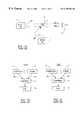
- FIG. 1Aa basic schematic of a prior art optical combiner 2 .
- Optical combiner 2receives rays from an image 4 and an image 5 .
- the rays from image 4are reflected off of the combiner 2 , as represented by arrow 3 B, and received by an eye 6 .
- the rays from image 5are transmitted through combiner 2 , as represented by arrow 3 A, and also received by the eye 6 .
- eye 6receives one superimposed image created from the rays 3 A from image 5 and from the rays 3 B from image 4 .
- the optical equation for the received superimposed imageis:
- Rays 3 A′ and rays 3 B′are defined as:
- the ratio of mix of rays 3 A′ and rays 3 B′need to be determined in advance.
- the resultant imageis always less than or equal to 100%, or the sum of the received relative rays 3 A and 3 B.
- FIGS. 1B-Cwhich are now referred to are schematic illustrations of the typical day and night biases of the standard prior art combiner system.
- FIG. 1Billustrates an example of nighttime transmission of symbology 4 and scene image 5 transmitting two rays 3 A-B, through a combiner 2 ′ to an eye 6 .
- FIG. 1Cillustrates an example of daytime transmission of symbology 4 and scene 5 transmitting two rays, represented by arrows 3 C-D, through a combiner 2 ′′ to an eye 6 .
- the strength of ray 3 A from the scene 5is required to be greatest due to the poor image produced by the darkness. Conversely, the darkness creates enough contrast for a minimum strength ray 3 B from the symbology 4 .
- the two rays 3 A and 3 Bare then combined through combiner 2 ′ with a resultant image received by eye 6 of superimposed symbols 4 on the scene 5 .
- a single electronic signal processing meansis employed.
- one of the image sourcesis a Charge Coupled Device (CCD) converting image intensifier (I 2 ) image
- the other image sourceis a camera converting a direct scene or FLIR.
- the two image sourcesare sampled to two separate digital mediums, and the two resultant images are combined pixel by pixel to one digital image using signal processing.
- the combined digital imageis then displayed on a visible image medium (display).
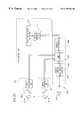
- FIG. 2which is now referred to herein shows a prior art digital sampling and signal processing unit 70 for combining two images in a HMD display.
- This systemis equally applicable to a non-HMD application where two image sources are to be combined.
- a generated night imageis described hereinbelow.
- Prior art system 70consists of an image sensor unit 72 , an electronic memory, a memory/signal-processing unit 74 and a display unit 76 .
- Sensor unit 72contains two or more separate image sources, which may be physically apart.
- a first image source 78 Amay consist of an I 2 generated image and a second image source 78 B may consist of a Forward Looking Infra Red (FLIR) image, any other desirable combination, or image sources.
- the I 2 source 78 Ais converted to a video signal by a CCD, ICCD, or a camera 80 A, and the FLIR source 78 B is converted to a video signal by an image converter 80 B.
- Both “video” signalsare respectively sampled and converted to a digital signal by sampler/analog-digital units 82 A and 82 B respectively.
- the digital signalsare then stored in respective memories 84 A and 84 B.
- a signal processor 86in conjunction with an image processor/timer 88 processes each designated corresponding pixel from memory 84 A and 84 B and combines them into a single memory 90 .
- the information in memory 90is converted by a display interface/digital-analog converter 92 and transferred to display unit 76 for display.
- a display electronics 94 , a display media or source 96 and an eye optics relay 98display a combined picture for an observer from the data stored in memory 90 .
- An analog imageis generated if the display source 96 is a Cathode Ray Tube (CRT).
- a digital imageis generated if the display source 96 is an Active Matrix-Liquid Color Display (AM-LCD), Active Matrix-Electro Luminect (AM-EL), Plasma Display Panel (PDP), flat panel display (FPD) or any other display media.
- A-LCDActive Matrix-Liquid Color Display
- AM-ELActive Matrix-Electro Luminect
- PDPPlasma Display Panel
- FPDflat panel display
- processing unit 74is cumbersome and some of its elements must be installed off-helmet.
- the present inventionprovides an improved head mounted display which provides night and day vision capability.
- the present inventionfurther provides a method for combining two images using time sharing, allowing continuous intensity variation for each of two superimposed images to optimize image quality in the light of prevailing external conditions useful in general and for HMD viewers.
- the head mounted displayis mounted such that the optical assembly providing night vision capabilities is located generally in the same height of the pilot's eyes, whereby elevation estimations made by the pilot are improved.
- the head mounted displayprovides simultaneously direct image amplified night image and synthetic image, whereby the pilot receives information of the scenery from three different sources.
- the head mounted displayincludes a recording channel for recording the scenery viewed by the pilot throughout the flight.
- the head mounted display of the present inventionincludes modular assemblies which together are replaceable and changeable.
- the head mounted display of the present inventioncontains a combiner which provides colored and monochrome symbology giving high contrast over the scenery.
- the head mounted display of the present inventioncontains a combiner or visor which provides a colored and monochrome symbology over an indirect sensor image.
- a sensor generated image fusion capability of images from two indirect sensors or two ordinary images or a combination of direct and indirect images in a helmet mounted displayis provided.
- a helmet mounted displayfor mounting on a helmet which includes a supporting arc removably mounted at least at one point to the helmet, a visor, mounted on the arc and at least one optical system, side mounted on the supporting arc, for projecting an image on the visor from the side of the pilot's head.
- the structure of the helmethas a personally fitted interface for mounting the display module on it.
- the visorincludes two side arms for connecting to the supporting arc and a mirror, generally shaped in the form of glasses.
- the mirroris semi-transparent, so as to enable visible light from the external scene to pass therethrough as well as to reflect the image.
- the mirrorcan be non-transparent.
- optical systemswhich can be used, according to the invention are selected from the group consisting of: a light night intensifying unit and an optical projecting unit.
- the display image unitis selected from the group consisting of: a cathode ray tube (CRT), a liquid crystal display (LCD), a deformable mirror device and a digital mirror device.
- the helmet mounted displaymay further include a power interface for connecting to an external power supply unit.
- the helmet mounted displaymay further include a portable power supply unit, which is connected to the power interface.
- the visormay be connected to the supporting arc via a hinge which enables tilting of the visor up or down.
- An optical system which is mounted on the helmet mounted displaymay be connected to the supporting arc via the hinge or be firmly connected thereto.
- a head mounted displayfor mounting on the helmet which includes means enabling direct vision of scenery, means enabling intensified vision of at least part of the scenery and means for providing a synthetic image superimposed on the image by the direct vision and the image provided by the intensified vision.
- three imagesare displayed to a pilot wearing the helmet, with the mounted display.
- a head mounted displayfor mounting on a helmet which includes a recording system for recording an image generally simultaneously projected onto a visor of the head mounted display and means for intensifying an image of a scenery to be viewed.
- a helmet mounted systemfor displaying high contrast images.
- a source of lightwhich is preferably a switch red, green and blue array for producing color images, is transmitted off a digital reflective device.
- the source of lightis a switched colored array which produces monochromatic images.
- the digital reflective devicecontains a plurality of micromirrors for deflecting the source of light in a pixelated manner via a plurality of pixels.
- Each pixelcorresponds to a deflection of each micromirror on the digital reflective device and the intensity of each pixel is proportional to the duration of the deflection.
- the duration of defectionis adjustable per pixel and is a function of time.
- the digital reflective deviceis either a digital micromirror display or a reflective active matrix-liquid crystal display. And the deflection or positioning of the digital reflective device is controlled by an image processor and timing circuit or any type of digital driving circuit.
- the systemreceives a source of light and at least one optical image produced by a display optical system, and superposes said source of light over said optical image.
- the systemswitches between the source of light and the optical image as a function of time.
- the superposition intensity of each imageis continuously varied in a pixelated manner.
- the display optical systemis either a reflective device which generates images, or a emissive device which generates images.
- the at least first imageis produce by at least one first image source and the at least one second image is produced by a at least one second image source.
- the imagespreferably can be sensed and/or displayed by any desired pixel by pixel ratio.
- a method for combining two imagesthe steps include creating a first image, creating a second image, and switching between the first image and the second image.
- the methodcreates a viewable combined single image, such that the switching is timed on a pixel by pixel basis to vary the intensity of each of said first and said second image on a pixel by pixel basis.
- FIG. 1Ais a schematic illustration of a prior art optical combiner
- FIGS. 1B-1Care schematic illustrations of the conflicting requirements for transmission in a prior art optical combiner used to combine a direct scene and an indirect source in a helmet mounted display;
- FIG. 2is a schematic illustration of a prior art electro-optic system for combining two images to give pixel by pixel control of the ratio of intensities of the respective images;
- FIG. 3is a schematic isometrix illustration of a helmet, with a head mounted display, constructed and operative in accordance with a preferred embodiment of the present invention
- FIG. 4Ais a schematic side view of the helmet and the head mounted display of FIG. 3;
- FIG. 4Bis a schematic top view of the helmet and the head mounted display of FIG. 3;
- FIG. 5is a schematic isometrix illustration of the head mounted display of FIG. 3;
- FIGS. 6A-6Dare schematic pictorial illustrations illustrating the steps of wearing the helmet with the head mounted display of FIG. 3;
- FIGS. 7A and 7Bare schematic isometrix illustrations of a helmet, constructed and operative in accordance with another preferred embodiment of the present invention.
- FIG. 8is a schematic pictorial illustration of a helmet and an optical system detachable arrangement, constructed and operative in accordance with a further preferred embodiment of the present invention.
- FIG. 9is a schematic pictorial illustration of a helmet with a detachable CRT and a power supply connector, constructed and operative in accordance with yet another preferred embodiment of the present invention.
- FIG. 10is a schematic illustration of an optical system and the optical path therefore, constructed and operative in accordance with yet another embodiment of the invention.
- FIG. 11is a schematic pictorial illustration of three simultaneous images of the flight route provided to the pilot;
- FIG. 12is a pictorial illustration of an image which is projected by an optical system on a visor
- FIGS. 13A-13Care schematic illustrations of three alternative preferred embodiments of the optical path of light provided from the light intensifier and an additional illuminating unit to the visor, functioning also as a combiner;
- FIG. 14Ais a schematic illustration of circuit for controlling the operation a prior art power circuit for providing power to a night light intensifier
- FIG. 14Bis a schematic illustration of a power circuit for providing variable intensity control over a night light intensifier
- FIG. 15is a top view schematic illustration of a helmet system constructed and operative with a recording unit in accordance with another preferred embodiment of the present invention.
- FIG. 16is a schematic illustration in detail of the electro-optical system of FIG. 15 and the optical path of light rays therein;
- FIG. 17Ais a prior art schematic illustration of the geometry of a DMD
- FIG. 17Bis a prior art utilization of a DMD utilized to produce a projected digital image
- FIG. 18Ais a partial schematic illustration of an optical system according to a preferred embodiment of the invention for a reflection device generated symbology image superimposed on an external scene in a HMD;
- FIG. 18Bis an illustration of the optical design of the optical system of FIG. 18 and the optical path of light rays therein;
- FIG. 19Ais a partial schematic illustration of an optical system utilizing a DMD generated symbology image superimposed on an indirect image in a HMD;
- FIG. 19Bis an illustration of the optical design of the optical system of FIG. 19 A and the optical path of light rays therein;
- FIG. 20is a schematic illustration of a DMD system for image fusion according to a preferred embodiment of the present invention.
- FIG. 21is a partial schematic illustration of an optical system utilizing a DMD to provide image fusion in a HMD.
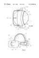
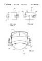
- FIG. 3is a schematic isometrix illustration of a helmet 10 and a head mounted display 14 , constructed and operative in accordance with a preferred embodiment of the present invention.
- FIG. 4Ais a schematic side view of the helmet 10 .
- FIG. 4Bis a schematic top view of the helmet 10 .
- FIG. 5is a schematic isometrix illustration of the head mounted display of FIG. 1 .
- Helmet 10includes a helmet body 12 , and helmet mounted display 14 including a visor 22 , a supporting arc 24 , and optical systems 17 A and 17 B. According to the invention, the optical systems 17 A and 17 B are mounted on each side of the arc 24 .
- the head mounted display 14includes an interchangeable interface 18 , mounted on the side of the arc 24 , for receiving there-into an optical system such as optical system 17 A.
- Each interchangeable interface 18is modified especially for a specific pilot, taking into account the exact shape of his skull, the location of his eyes, the orientation of his pupils and the like.
- the head mounted display 14can be adjusted to a variety of head characteristics just by changing the interchangeable interface 18 , regardless of any anthropometrix differences between different heads.
- the personal interfacemay be a personally shaped post.
- the personal interfacemay be an individually shaped frame, into which each goggle is stuck. In this case, when the helmet is worn, the image is exactly in front of the eye of the pilot. Accordingly, the present invention eliminates the need for adjusting mechanisms, reduces the total weight of the helmet and adds to the accuracy of pointing in space.
- each of optical systems 17 A and 17 Bgenerally coincide with the imaginary plane formed by the eyes and the ears of the pilot. Therefore, the light is directed to visor 22 from the side and not from above, as in the prior art. This is significantly important since, the height of the projecting area 25 can be fixed, thus eliminating any vertical shifts of the projecting area 25 which, as will be readily appreciated, are extremely dangerous.
- the optical systems 17 A and 17 Bcan be any combination of any type of vision, data or detection systems such as a night light intensifier, a data displaying system, a look in the eye detection system and the like.
- the weight distribution of the helmet 10is around the helmet rather than on top, as in the prior art.
- the helmetis far more balanced than prior art helmets, which use top or rear optical mounted devices.
- the optical systems 17 A and 17 Bare mounted on the sides of the supporting arc 24 .
- the visor 22is also connected to the sides of the supporting arc 24 and is adapted to swing upward.
- the head mounted display 14which includes the arc 24 , the optical systems 17 and the visor 22 , can be easily detached and removed from the helmet body 12 and replaced with other helmet accessories.
- the assemblycan be attached to the helmet body 12 on either side, references 21 and 23 .
- the supporting arc 24is manufactured from flexible materials.
- connecting locationcan be a hook, a Velcro connector and the like.
- each of the optical systems 17 A and 17 Bcan be detached from the supporting arc 24 and replaced with a variety of optical units as described in detail herein after.
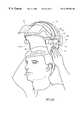
- FIGS. 6A, 6 B, 6 C and 6 Dare schematic pictorial illustrations illustrating the steps of wearing the helmet 10 including the head mounted display 14 , according to the present invention.
- the visor 22is flipped up so as to maximize the open area provided to receive the head of the pilot. Then, as can be seen in FIG. 6B, the pilot holds both sides of the helmet body 12 and mounts the helmet on his head. Since the supporting arc 24 is made to be flexible, the pilot can pull both sides 27 and 29 , of the helmet, away from each other in order to momentarily expand the open area provided to receive his head without changing the optical path of the head mounted display 14 .
- the visorcan be flipped down (FIG. 6 D).
- the visor 22located relatively far from the eyes and face of the pilot.
- This unique structure of the helmet 10combined with the above described way of mounting it on, enable pilots who wear eye glasses to put the helmet on and take it off, without removing their eye glasses.
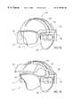
- FIGS. 7A and 7Bare schematic isometrix illustrations of a helmet, generally referenced 50 , constructed and operative in accordance with another preferred embodiment of the present invention.
- Helmet 50includes a helmet body 60 and a head mounted display 52 which includes a visor 54 , an arc 62 an optical system 56 , attached on the left side of the visor 54 and an optical system 57 , attached on the right side of the visor 54 .
- Visor 54is connected to arc 62 by a hinge 58 , which allows it to rotate upward (FIG. 7B) and downward (FIG. 7 A).
- Optical system 56is firmly connected to the supporting arc 62 and thus, is firm in its position.
- FIG. 8is a schematic pictorial illustration of a helmet with an optical system detachable arrangement, constructed and operative in accordance with a further preferred embodiment of the present invention.
- Helmet 100includes a visor 102 , an arc 104 and an optical system base 106 .
- a first type of an optical systemwhich in the present example is a night light intensifier 110 , is mounted on the optical system base 106 .
- the night light intensifier 110is secured on the optical system base 106 by a fast opening knob 108 , which allows rapid attaching and detaching of the optical system to the optical system base 106 .
- the night light intensifier 110can be replaced, for example, with a visor display unit 112 , such as a Cathode Ray Tube (CRT) wherein the unit 112 also includes a fast opening knob 114 . It will be appreciated that a securing mechanism can also be located on the optical system base 106 .
- a visor display unit 112such as a Cathode Ray Tube (CRT) wherein the unit 112 also includes a fast opening knob 114 .
- CTRCathode Ray Tube
- a securing mechanismcan also be located on the optical system base 106 .
- An optical system which is mounted on the optical system base 106can also be connected thereto via a communication interface (not shown) for intercommunication with an optical system mounted on the other side of the helmet 100 or with any airborne devices aboard the helicopter.
- FIG. 9is a schematic pictorial illustration of a helmet with a detachable CRT and a power supply connector, constructed and operative in accordance with yet another preferred embodiment of the present invention.
- Helmet 150includes an arc 154 , a visor 152 , an optical system base 156 and a communication and power cable 162 . Similarly to helmet 100 of FIG. 8, helmet 150 is adapted for interchangeable optical systems.
- An optical system 158which in the present example is a look in the eye detection device, is mounted on the optical system base 156 .
- the communication and power cable 162can be connected either to equipment installed on board the helicopter for power supply and data exchange.
- the communication and power cable 162can also connect to a power source worn by the pilot. This arrangement is extremely useful since it enables the pilot to be completely mobile, inside as well as outside the helicopter, with the helmet systems fully operational at all times.
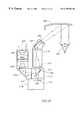
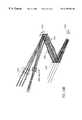
- FIG. 10is a schematic illustration of an optical system, generally designated 200 , and the optical path therefore, constructed and operative in accordance with yet another embodiment of the invention.
- FIG. 11is a pictorial illustration of the total superposed images formed on the visor 202 by system 200 .
- System 200includes an image intensifier 206 , a plurality of lenses 204 , 208 , 216 , 218 and 220 , a projecting unit 215 , two mirrors 210 and 224 and a semi transparent mirror 212 .
- projecting unit 215includes a Cathode Ray Tube (CRT) 214 .
- Image intensifier 206detects and image of a scenery through lens 204 .
- the image intensifier 206produces an intensified image (represented by light rays 217 ) of the scenery and directs it to mirror 210 , through lens 208 .
- Mirror 210further directs the intensified 217 image to mirror 212 .
- CRT 214generates a digital image (represented by light rays 213 ) and directs it through semi-transparent mirror 212 .
- Semi-transparent mirror 212combines the digital image with the intensified image and directs the combined images to the visor 202 via lenses 216 and 218 , mirror 224 and lens 220 .
- the combined imageis then reflected from the visor 202 for viewing by the pilot, represented by an eye 222 .
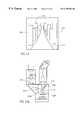
- the total image formed on the visor 202includes a combination of three images.
- a first imagewhich includes the images of airplane 250 , house 252 , car 254 , container 256 and road 258 , is an image of the scenery.
- a second imagewhich includes circles 260 and 264 is the image detected by image intensifier 206 .
- This imageincludes intensified details of objects of the first image, which are included therein.
- the image intensifier 206detects the image of car 254 and provides an image of it, which adds to the first image. In FIG. 11, this is represented by thickening the lines of objects in circles 260 and 264 .
- the third image displayed on square 262is a digital image formed by the CRT 214 . It will be appreciated that CRT 214 is operative to produce digital images which include any type of aeronautical instrument data such as altitude, latitude, firing information and the like.
- FIG. 12is a pictorial illustration of a superposed images formed on the visor 202 by system 200 .
- the imageincludes an image of a road 370 and images of targets, generally referenced 372 , 374 and 376 .
- the system 200is a modular system which is operative to provide different interchangeable projecting units 216 .
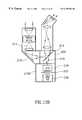
- FIGS. 13A, 13 B and 13 Care partial schematic illustrations of optical system 200 and the optical path therefore, constructed and operative in accordance with further embodiments of the invention.
- the system 200includes a projecting unit 215 A which includes an electro-luminance element 226 .
- the electro-luminance element 226generates a digital image (represented by light rays 219 ) and directs it at semi transparent mirror 212 .
- the semi-transparent mirror 212combines the digital image with the intensified image and further directs the combined image through the lenses of system 200 towards visor 202 .
- the system 200includes an illuminating unit 215 B which includes a light source 230 , a screen 232 and a Liquid Crystal Device (LCD) 234 .
- Light source 230generates a light beam and directs it to screen 232 .
- the screen 232spreads the beam evenly and further directs it to the LCD 234 .
- the LCD 234controls and moderates passage of the light beam therethrough and thus produces a digital image (represented by light rays 221 ).
- the digital imageis further directed to semi transparent mirror 212 which combines it with the intensified image and further directs the combined image trough the lenses of system 200 towards visor 202 .
- the system 200includes an illuminating unit 215 C which includes a light source 235 , a screen 236 , two lenses 238 and 242 , a mirror 246 and a computer controlled mirror based device 240 .
- the computer controlled mirror based device 240can be a Deformable Mirror Device, a Digital Mirror Device (DMD) and the like.
- Light source 235generates a light beam and directs it to screen 236 .
- the screen 236spreads the beam evenly and further directs it to the computer controlled mirror based device 240 , via mirror 246 and lens 238 .
- the computer controlled mirror based device 240reflects some of the light, thus producing a digital image (represented by light rays 223 ).
- the digital imageis further directed to semi transparent mirror 212 , via lens 242 and mask screen 244 .
- the semi transparent mirror 212combines the digital image with the intensified image and further directs the combined image through the lenses of system 200 towards visor 202 .
- FIG. 14Ais a schematic illustration of a prior art circuit, referenced 6 , for controlling the operation the intensity of a CRT of a night light intensifier.
- the power circuit 6includes a Cathode Ray Tube 2 (CRT) and a power supply unit 4 , which is connected thereto.
- the power supply unitprovides power to the CRT 2 and the CRT 2 provides feedback information to the power supply unit 4 , so as to moderate the amount of power supplied therefrom, according to a predetermined level.
- These circuitsdo not enable the pilot to intervene in the feedback process so as to adjust the intensity according to his needs.
- FIG. 14Bis a schematic illustration of a circuit, generally referenced 306 , for controlling the operation of a CRT, constructed and operative in accordance with a preferred embodiment of the invention.
- Circuit 306includes a Cathode Ray Tube 300 (CRT), a power supply unit 302 , and a variable resistor 304 .
- the power supply unit 302is connected to the CRT 306 , providing power thereto.
- the CRT 306provides feedback information to the power supply unit 302 , so as to moderate the amount of power supplied therefrom, according to a selected level.
- the variable resistor 304interconnects between the power supply unit 302 and the CRT 306 and enables the user to select an intensity level according to his needs.
- FIG. 15is a top view schematic illustration of a helmet with a head mounted display, constructed and operative with a recording unit in accordance with another preferred embodiment of the present invention.
- the helmet system 310includes a helmet body 314 and a head mounted display 312 mounted thereon.
- Head mounted display 312includes a rigid arc 316 , a visor 318 , an electro-optical system 320 and a recording system 322 .
- the electro-optical system 320is a CRT based system which is similar to system 200 , described hereinabove with reference to FIG. 11 .
- the recording system 322is a Charge Coupled Device (CCD) based unit for recording the image intensified by the right light intensifier.
- CCDCharge Coupled Device
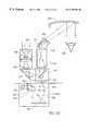
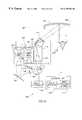
- FIG. 16is a schematic illustration of the recording system 322 and the optical path of light rays therein.
- the electro-optical system 322includes a light intensifier 326 , a Charge Coupled Device 338 (CCD), lenses 324 , 328 , 334 , 340 , 342 and 346 , mirrors 330 , 336 and 344 and a splitting element 332 .
- Light intensifier 326detects and image of a scenery, through lens 324 .
- the light intensifier 326produces an intensified image (represented by light rays 327 ) of the scenery and directs it to mirror 330 , through lens 328 .
- Mirror 328further directs the intensified image to splitting element 332 .
- the splitting element 332splits the image 327 into a first image (represented by light ray 325 ) and a second image (represented by light ray 329 ).
- the first image 325passes through the splitting element 332 and directed to mirror 336 via lens 334 .
- the mirror 336further directs the image 325 to CCD 338 .
- the CCD 338detects the image 325 , converts it to digital data and transfers the digital data to a storage unit thereby completing a procedure of image recording.
- the second image 329is reflected from the splitting element 332 and further directed to mirror 344 , via lenses 340 and 342 .
- Mirror 344reflects the second image 329 towards the visor 318 , via lens 346 .
- Pilotrepresented by eye 350 , is able to see the second image 329 being reflected from the visor 318 .
- a method of solving the difficulties associated with optimizing combiner performance between day and night, apart from using different combiners,is to utilize a digital micro-mirror display (DMD), produced by companies such as Texas Instruments of Dallas, Tex., U.S.A. or a reflective active metrix-LCD (R-LCD) unit in place of the combiner.
- DMDdigital micro-mirror display
- R-LCD unitsare produced by companies such as Displaytech of Longmont, Colo., U.S.A. Microdisplay Corporation of San Pueblo, Calif. U.S.A., or CRL of Middlesex, UK, or any other type of pixelated addressing device.
- DMD's and R-LCD unitsfacilitate pixel by pixel intensity control of direct and indirect images giving the combiner the flexibility to operate at this optimum under all conditions.
- the DMD and the R-LCDfurther provide the user the flexibility to shift between one or more received images on a pixel by pixel basis, thus providing a time-shared combiner.
- the DMDcan be utilized to generate symbology without the use of a CRT.
- references to a direct imagerefer to an image which is formed without image processing or transferring
- references to an indirect imagerefer to an image which is formed with image processing or transferring.
- FIGS. 17A and 17Bshow a DMD, such as that produced by Texas Instruments of Dallas, Tex., U.S.A.
- a DMDis a mirror for reflecting light, which has individually rotatable mirrors for deflecting light operable at the level of pixels.
- FIG. 17Ashows the configuration at the surface and
- FIG. 17Bshows the DMD in use as a means of directly generating a digital image in a projection TV.
- each DMDis made up of a large number of rotatable mirrors 400 .
- Mirrors 400are capable of movement to deflect the angle of their surface.
- Each mirror (addressable) 400is mounted on a mirror support post 402 attached to a torsion hinge 404 supported by at least one hinge support post 406 .
- Torsion hinge 404facilitate torsional deflection of the surface of each mirror 400 . The deflection occurs about a diagonal axis joining two hinge support posts 406 . Rotation is facilitated by an address electrode 408 and the mirror 400 is stopped by a landing tip 410 .
- a DMDis used to generate a digital image on a screen, such as in a projection TV system.
- a white light source 412is focusing by lenses 414 A and 414 B and a Digital Light Processing (DLP) board 416 onto a DMD 413 .
- DLPDigital Light Processing
- a processor 418 and a memory 420converts the deflected light into a video signal which is stored in a memory 420 . This action is executed simultaneously for all the DMDs 413 , each pixel generating a separate frame or image.
- the video signalis retrieved from memory 420 , and a projection lens 422 then generates an image on a screen 424 .
- a color pictureis created by rotating a spectral filter through the white beam allowing red, green or blue to pass through it at a rate which is faster than the human eye can detect, thus three color pictures with the same intensity distribution are superimposed for each frame.
- each pixelis time modulated by switching the mirror on or off rapidly switching with respect to each color, in addition to the intensity pattern.
- FIGS. 18A and 19Aillustrate optical systems 500 and 600 utilizing electronic time-shared combiners in a helmet mounted preferred embodiment, constructed and operative in accordance with further embodiments of the invention.
- the combiners utilized in optical systems 500 and 600provide combining flexibility for both day and night usages. Similar elements which have similar numerals to those of optical system 200 (FIG. 10) will not be further described herein.
- FIGS. 18B and 19Billustrate the optical schematic of systems 500 and 600 , respectively, and the optical path of light rays therein.
- optical systems described hereinbelowcomprise a DMD, referenced 510 .
- optical system 500can comprise an R-LCD.
- the optical systems described hereinbelowcan alternatively embody an image intensifier (I 2 ), a cathode ray tube, an image intensifier coupled with a charge coupled device (ICCD) camera, a forward looking infra red (FLIR), an AM-LCD, an AM-EL, an electronic bombard charge coupling device (EBCCD) and/or a Programmable Logic Device (PLD).
- I 2image intensifier
- ICCDcharge coupled device
- FLIRforward looking infra red
- AM-LCDAM-LCD
- AM-ELAM-EL
- ECCDelectronic bombard charge coupling device
- PLDProgrammable Logic Device
- optical system 500is utilized to create colored and monochrome symbology with a high contrast over a bright scene.
- Optical system 500comprises an electronic unit 511 , which controls the deflection position of DMD 510 and more specifically, the deflection position of mirrors 400 (FIG. 17A, not shown in FIG. 18) in DMD 510 .
- Optical system 500also comprises three highly efficient colored light sources 515 in red, blue and green.
- Electronic unit 511comprises an image processor/timing unit 512 and a display interface 513 .
- a signal corresponding to a desired deflection position of DMD 510is fed into unit 512 , and transferred to display interface 513 .
- the signalis then transferred to a display electronics 514 which is joined to DMD 510 .
- Display electronics 514sends signals to DMD 510 controlling each pixelated mirrors 400 (FIG. 17A) in DMD 510 and thus controlling which light source 515 is reflected off of pixelated mirrors 400 .
- the light source 515 reflected off the pixelated mirror 400 in DMD 510is focused by optics 224 and 220 , reflected off a visor 220 and eventually received by an eye 222 . Simultaneously an image from outside scene 520 is transferred through visor 220 , and received by eye 222 . Eye 222 thus receives the pixelated image from the DMD 510 superimposed on the image received from the outside scene 520 .
- Colored light sources 515may be created by colored lamps or filtered white light and must be rapidly switchable, for example, fluorescent, arc-lamp, lasers, laser diode, LED or flash lamp.
- monochrome symbologyis achieved by not switching colored light sources 515 and thus giving continuous single color light.
- the DMD/R-LCD 510is in the focal plane of the HMD optics so the viewer sees light reflected from the DMD/R-LCD.
- Each mirror 400 (FIG. 17A) on the DMDis electrically manipulated by display electronics 614 which receive the pixel information from electronic unit 511 to move angularly so as to reflect light corresponding to each pixel of an image either to the eye 222 of the pilot or elsewhere.
- a symbology imagemay be generated and superimposed on the outside scene 520 .
- Color symbologyis achieved by rapid switching of light sources 515 sequentially to give red, blue and green primary colors for each particular frame.
- An ordinary white or colored light sourceyields a monochromic image.
- FIG. 18Ban illustration of the optical design implementation of optical system 500 .
- FIG. 18Billustrates the optical path of the light rays as they transmitted from light source 515 through system 500 to eye 222 .
- FIG. 19Aillustrates optical system 600 .
- Optical system 600is configured for combining an indirect scene such as that produced by an image intensifier 206 with a symbology scene. Elements which are the same as those in optical system 200 are similarly labeled and will not be described further.
- System 600comprises electronic unit 511 and image processor/timing unit 512 , display interface 513 , and display electronics 514 , which are joined to DMD 510 .
- Display electronics 514sends signals to DMD 510 for controlling the deflection of mirrors 400 (FIG. 17A) in DMD 510 .
- System 600also comprises three colored light sources 515 , as described hereinabove in optical system 500 , in red, blue and green.
- DMD 510produces a colored symbology image via the usage of light sources 515 .
- the colored symbology imageis combined with an indirect scene from the image intensifier 206 . The sequence of events required to produce a combined indirect and symbology image is described below.
- Image intensifier 206projects an image of a scene 520 through lens 204 .
- the image intensifier 206produces an intensified image (represented by light rays 217 ) of the scene which travels through lens 206 to mirror 210 .
- Mirror 210then directs the intensified rays 217 to DMD 510 .
- Mirror elements 400 (FIG. 17A) on DMD 510deflect at an angle which directs the image of the scene via lenses 216 and 218 , mirror 224 and lens 220 to visor 202 .
- Electronic unit 511sends instruction to display electronics 514 which electrically manipulates the deflection angle of each mirror 400 (FIG. 17A) on the DMD.
- the image reflected off mirror 400is then reflected from the visor 202 to the viewer, represented by eye 222 .
- the combined imagesare superimposed with the direct scene (“sensor fusion”) which came through the visor ( 520 ), which acts as an optical combiner.
- the switched red, green and blue rays emanating from colored light sources 515are permanently incident on mirrors 400 of DMD 510 .
- the intensified image 217is displayed on visor 202 , come of the mirrors 400 are then required to generate a particular symbology picture.
- These mirrors 400are next deflected to an angle which directs a pixelated symbology image, represented by rays 640 , via lenses 216 and 218 , mirror 224 and lens 220 reflected off visor 202 and onto eye 222 .
- the symbology image 640is built up by the mirrors 400 which are deflected to produce a pixel of light on visor 202 , whilst the non-deflected mirrors 400 produce the intensified image 217 .
- the duration of deflection of a mirror 400determines the color mix and brightness of the final image as it determines the proportion of time each of the switched red, blue and green rays are incident on DMD 510 .
- a monochrome symbology image 640is achieved by the use of a monochromatic light source wherein colored light sources 515 are permanently on.
- the length of time that a mirror 400 is deflectedcreates the brightness level of that particular pixel. This is true in the case of both the intensified image 217 or symbology image 640 .
- rays 640represent the path of intensified image 217 from DMD 510 when mirrors 400 of DMD 510 are oriented to deflect intensified image 217 to visor 202 . It should also be noted that the switch between the projection of intensified image 217 onto visor 202 and the projection of symbology image 640 is done in such a short time span that eye 222 does not recognize the switch.
- each DMD in optical system 600projects separately and deflects at full intensity from its given source—either intensified image 217 or symbology image 640 —optical system 600 projects the whole intensity of both intensified image 217 and symbology image 640 . This is not the case with traditional combiner technology where part of each image must be lost in the course of their combination.
- the intensity of each imagemay be varied from zero to a maximum independently of the other. This is achieved by varying the brightness of each source image intensifier 206 or light source 515 or mirrors deflection angles.
- pixel by pixel control of the intensity of each respective image 217 and 640is achievable by varying the individual position of particular mirrors 400 during the respective generation of images 217 and 640 .
- the angles of each particular mirror 400 , and the individual duration of deflectioncan be altered with each change in the scenes external brightness/darkness.
- optical system 600replace image intensifier 206 with any of the following, but not limited to: a CRT, an ICCD, a forward locking infra red (FLIR), an Active Matrix-LCD, an Active Matrix-Elor, an electronic bombard charge coupling device (EBCCD), and a PLD, or any type of display source.
- a CRTa CRT
- ICCDa forward locking infra red
- FLIRforward locking infra red
- Active Matrix-LCDActive Matrix-Elor
- ECCDelectronic bombard charge coupling device
- PLDPLD
- FIG. 19Ban illustration of the optical design implementation of optical system 600 .
- FIG. 19Billustrates the optical path of the light rays as they transmitted from light source 515 and image intensifier 206 , combined and transmitted through system 600 to eye 222 .
- Optical systems 500 and 600are merely examples of the use of a DMD to combine and produce images as applied to HMD's in general. Many alternative configurations of optical systems both within HMD's and without are possible.
- FIG. 20is a schematic illustration of a DMD system for image fusion.
- FIG. 21is a partial schematic illustration of an optical system 700 , utilizing a DMD to provide image fusion in a HMD or other sight application. Elements which are the same as those in previously described optical systems are similarly labeled and will not be described further.
- Image fusionis the process of fusing or combining two images, either a direct and indirect or two direct images, into a single signal.
- Two images of the same scenemay be desirable in an instance such as a foggy or smoky scene, in which case one source may be an I 2 and the other source may be a FLIR.
- the processinvolves digital fusion of two digital signals, and projection of the signal fused image.
- FIG. 20shows a diagram of a system 650 used for combining two images 651 A and 651 B, both of which view the same scene.
- the two imagesare received by a first image source 652 and a second image source 654 and transferred to DMD 510 .
- System 650additionally comprises electronic unit 511 , similar to the one described in reference to FIG. 19, and a display unit 658 .
- Display unit 658contains display electronics 664 , DMD 510 and an optical relay 668 .
- Examples of relay 668are eye optics or projection screen optics.
- Image processor/timing unit 512sends a signal via display interface 513 and display electronics 664 to DMD 510 .
- DMD 510Upon receiving the signal DMD 510 alters the movement of mirrors 400 (FIG. 17 A), on a pixel by pixel basis, switching between receiving either image 651 A or 651 B.
- the received imageeither that of 651 A or 651 B, is transferred to relay 668 and viewed by an observer, represented by an eye 222 .
- Mirrors 400 (FIG. 17A) of DMD 510thus flip back and forth, alternating between the first image source 652 or a part of it, and the second image source 654 or a part of it. Furthermore, the intensity of individual pixels on first source 652 and second source 654 are controlled by varying the duration of deflection of mirror 400 (FIG. 17 A).
- eye 222receives nearly 100% of both images, one after the other, in a time shared fashion. This is in contrast to the illustration and description given hereinabove in reference to FIG. 2 .
- the final image as received by the viewer in FIG. 2was a simultaneous superimposed image of two scenes. As such, the final image was the sum of a relative percentage of each scene's reflected and transmitted rays, summed together to be equal to or less than 100%. Thus only a relative proportion of each image was received by the viewer, in the present invention 100% of each image, both image 651 A and 651 B, is received by the viewer.
- the second image sourceis black and conversely, when the second image source is reflected by DMD 400 , the first image source is black. Switching between the images occurs at such a fast rate that eye 222 does not register the switching and therefore, the first image source 652 appears to be superimposed on the second image source 654 . This superposition may be termed a “sensor fusion”.
- First and second image sources 652 and 654may both be direct scene images or indirect images such as those generated by I 2 , FLIR, EBCCD and CCD or they may be mixed, for example image source 652 may be an indirect image and image source 654 may be a direct scene image.
- the image processor 512 algorithmdetermines the image fusion degree per pixel.
- Relay 668may be either eye optics or a video or TV screen or any other suitable medium.
- FIG. 21shows an alternative embodiment 700 of DMD system 650 . Elements which are similar to those described in optical system 200 are similarly labeled and will not be further described. Similarly, parts equivalent to those described in system 650 are similarly labeled and will not be further described.
- FIG. 21illustrates image fusion utilizing a DMD in a HMD embodiment.
- An image of scene 651is converged by lens 204 and received by a first image source 652 .
- Source 652which is depicted in FIG. 21 as an I 2 for exemplary purposes only, may be any direct scene image units such as I 2 , FLIR and CCD or other suitable medium.
- the image received by source 652is further converged by lens 208 and mirror 210 , producing rays 708 .
- the scene 651is converged and received by a second image source 654 .
- the imageis further reflected from mirror 707 and converged by lens 706 , producing rays 709 .
- Rays 708 and 709are both received by DMD 510 , and more specifically mirrors 400 (FIG. 17A) which reside within DMD 510 .
- Mirrors 400 of DMD 510flip back and forth between rays 708 to rays 709 .
- the image deflected off mirrors 400 of DMD 510are focused by optics 216 , 218 and 200 , reflected off visor 202 , and received by eye 222 .
- the fast switch deflections of mirrors 400are automatically timed to appear to eye 222 that ray 708 is superimposed onto ray 709 , or visa versa.
- the timing and processing of this maneuveris achieved by an image processor/timing device 512 coupled to a display interface 513 which is coupled to a display electronics 664 .
- image 708 and 706appear superimposed to the eye and source fusion of first image source 652 and second image source 654 is achieved.
- Each individual mirror 400 (FIG. 17A) of DMD 510can be programmed with the desired deflection duration, thus controlling which pixels of images 708 and 709 are displayed and their respective intensities.
- the superimposed imagein addition to being viewed by eye 222 , can be displayed on a suitable recording/displaying device.
- Electronic unit 511can be coupled to a digital processor (not shown) which transfers the digital superimposed image to a digital recorder, TV screen, or other viewing medium.
- the recording unit 320(FIG. 15) can operate during daylight flight without image intensifier 326 .
- Another exampleis to replace the unit 320 with a different light source and the like.
- the methods utilized in optical systems 500 , 600 , and 700 for creating symbology over a bright scene and for combining an indirect scene with a symbology scenemay be utilized in non-HMD applications.
Landscapes
- Physics & Mathematics (AREA)
- General Physics & Mathematics (AREA)
- Optics & Photonics (AREA)
- Astronomy & Astrophysics (AREA)
Abstract
Description
Claims (26)
Applications Claiming Priority (4)
| Application Number | Priority Date | Filing Date | Title |
|---|---|---|---|
| IL12292998AIL122929A0 (en) | 1998-01-13 | 1998-01-13 | Head mounted display |
| IL122929 | 1998-01-13 | ||
| IL12672698AIL126726A (en) | 1998-10-22 | 1998-10-22 | Optical system for day and night use |
| IL126726 | 1998-10-22 |
Publications (1)
| Publication Number | Publication Date |
|---|---|
| US6195206B1true US6195206B1 (en) | 2001-02-27 |
Family
ID=26323577
Family Applications (1)
| Application Number | Title | Priority Date | Filing Date |
|---|---|---|---|
| US09/228,418Expired - LifetimeUS6195206B1 (en) | 1998-01-13 | 1999-01-12 | Optical system for day and night use |
Country Status (1)
| Country | Link |
|---|---|
| US (1) | US6195206B1 (en) |
Cited By (95)
| Publication number | Priority date | Publication date | Assignee | Title |
|---|---|---|---|---|
| US6304386B1 (en)* | 1997-06-20 | 2001-10-16 | Sextant Avionique | Display device for helmet-mounted display |
| US20020030163A1 (en)* | 2000-08-09 | 2002-03-14 | Zhang Evan Y.W. | Image intensifier and LWIR fusion/combination system |
| US6560029B1 (en) | 2001-12-21 | 2003-05-06 | Itt Manufacturing Enterprises, Inc. | Video enhanced night vision goggle |
| WO2003105084A2 (en) | 2002-06-06 | 2003-12-18 | Litton Systems, Inc. | Integrated display image intensifier assembly |
| WO2003060590A3 (en)* | 2001-12-21 | 2004-02-05 | Itt Mfg Enterprises Inc | Video enhanced night vision goggle |
| US20040042086A1 (en)* | 2002-06-05 | 2004-03-04 | Litton Systems, Inc. | Enhanced night vision goggle assembly |
| US20040190109A1 (en)* | 2003-03-31 | 2004-09-30 | Kirch Steven J. | Light modulator with bi-directional drive |
| EP1580587A1 (en)* | 2004-03-25 | 2005-09-28 | Saab Ab | Helmet mounted display system with support unit |
| US20070084985A1 (en)* | 2005-10-07 | 2007-04-19 | Itt Manufacturing Enterprises, Inc. | Night vision goggle with separate camera and user ouput paths |
| WO2006110427A3 (en)* | 2005-04-07 | 2007-08-30 | Jabil Circuit Inc | Method and apparatus for an image presentation device with illumination control for black image processing |
| US20070236384A1 (en)* | 2006-02-12 | 2007-10-11 | Gennadii Ivtsenkov | Cost-effective friend-or-foe (IFF) combat infrared alert and identification system (CID) |
| US20090015735A1 (en)* | 2005-11-10 | 2009-01-15 | Michael David Simmonds | Display source |
| US20090045996A1 (en)* | 2007-03-13 | 2009-02-19 | Gennadii Ivtsenkov | Combined IR-RF combat identification friend-or-foe (IFF) system for the dismounted soldier |
| FR2925775A1 (en)* | 2007-12-21 | 2009-06-26 | Thales Sa | Electronic system connecting and disconnecting connector e.g. Mil-C-38999 type connector, for pilot helmet in e.g. aircraft, has male contacts of same portion positioned by displacing one with respect to another on plugging-in axis |
| US20100059561A1 (en)* | 2001-02-20 | 2010-03-11 | Michael Ellis | Reconfigurable personal display system and method |
| EP2199843A1 (en)* | 2008-12-19 | 2010-06-23 | BAE Systems PLC | Display system |
| WO2010070344A1 (en)* | 2008-12-19 | 2010-06-24 | Bae Systems Plc | Display system |
| US20100165470A1 (en)* | 2008-12-31 | 2010-07-01 | Texas Instruments Incorporated | Lens Array Element and Method |
| US7767963B1 (en) | 2006-12-08 | 2010-08-03 | Draeger Safety, Inc. | Thermal imaging camera internal damping system |
| WO2012016794A1 (en)* | 2010-08-02 | 2012-02-09 | Thales | Modular night-vision system with fused optical sensors |
| US20120081564A1 (en)* | 2009-06-10 | 2012-04-05 | Shimadzu Corporation | Head-mounted display |
| US20120162775A1 (en)* | 2010-12-23 | 2012-06-28 | Thales | Method for Correcting Hyperstereoscopy and Associated Helmet Viewing System |
| US20130120224A1 (en)* | 2011-11-11 | 2013-05-16 | Elmer S. Cajigas | Recalibration of a flexible mixed reality device |
| FR2988490A1 (en)* | 2012-03-22 | 2013-09-27 | Thales Sa | MODULAR HEADREST FOR PILOT |
| US20130322683A1 (en)* | 2012-05-30 | 2013-12-05 | Joel Jacobs | Customized head-mounted display device |
| US8675061B2 (en) | 2010-11-01 | 2014-03-18 | Richard D. Balentine | Digital video projection display system |
| US8817350B1 (en) | 2009-09-30 | 2014-08-26 | Rockwell Collins, Inc. | Optical displays |
| US9058510B1 (en)* | 2011-07-29 | 2015-06-16 | Rockwell Collins, Inc. | System for and method of controlling display characteristics including brightness and contrast |
| US9244281B1 (en) | 2013-09-26 | 2016-01-26 | Rockwell Collins, Inc. | Display system and method using a detached combiner |
| US9244280B1 (en) | 2014-03-25 | 2016-01-26 | Rockwell Collins, Inc. | Near eye display system and method for display enhancement or redundancy |
| US9274339B1 (en) | 2010-02-04 | 2016-03-01 | Rockwell Collins, Inc. | Worn display system and method without requiring real time tracking for boresight precision |
| US9341846B2 (en) | 2012-04-25 | 2016-05-17 | Rockwell Collins Inc. | Holographic wide angle display |
| US9366864B1 (en) | 2011-09-30 | 2016-06-14 | Rockwell Collins, Inc. | System for and method of displaying information without need for a combiner alignment detector |
| DE102014019358A1 (en) | 2014-12-22 | 2016-06-23 | Audi Ag | Display unit for a safety helmet |
| US9466150B2 (en) | 2013-11-06 | 2016-10-11 | Google Inc. | Composite image associated with a head-mountable device |
| US9507150B1 (en) | 2011-09-30 | 2016-11-29 | Rockwell Collins, Inc. | Head up display (HUD) using a bent waveguide assembly |
| US9519089B1 (en) | 2014-01-30 | 2016-12-13 | Rockwell Collins, Inc. | High performance volume phase gratings |
| US9523852B1 (en) | 2012-03-28 | 2016-12-20 | Rockwell Collins, Inc. | Micro collimator system and method for a head up display (HUD) |
| US9674413B1 (en) | 2013-04-17 | 2017-06-06 | Rockwell Collins, Inc. | Vision system and method having improved performance and solar mitigation |
| US9715110B1 (en) | 2014-09-25 | 2017-07-25 | Rockwell Collins, Inc. | Automotive head up display (HUD) |
| US9715067B1 (en) | 2011-09-30 | 2017-07-25 | Rockwell Collins, Inc. | Ultra-compact HUD utilizing waveguide pupil expander with surface relief gratings in high refractive index materials |
| US20180056098A1 (en)* | 2014-10-21 | 2018-03-01 | Evan John Kaye | Retractable headphone visor and air filtration system |
| US9933684B2 (en) | 2012-11-16 | 2018-04-03 | Rockwell Collins, Inc. | Transparent waveguide display providing upper and lower fields of view having a specific light output aperture configuration |
| US9992404B2 (en) | 2014-09-25 | 2018-06-05 | Avigilon Corporation | Method and system for adjusting camera focus to facilitate infrared imaging |
| US10088675B1 (en) | 2015-05-18 | 2018-10-02 | Rockwell Collins, Inc. | Turning light pipe for a pupil expansion system and method |
| US10108010B2 (en) | 2015-06-29 | 2018-10-23 | Rockwell Collins, Inc. | System for and method of integrating head up displays and head down displays |
| US10126552B2 (en) | 2015-05-18 | 2018-11-13 | Rockwell Collins, Inc. | Micro collimator system and method for a head up display (HUD) |
| US10156681B2 (en) | 2015-02-12 | 2018-12-18 | Digilens Inc. | Waveguide grating device |
| US10241330B2 (en) | 2014-09-19 | 2019-03-26 | Digilens, Inc. | Method and apparatus for generating input images for holographic waveguide displays |
| US10247943B1 (en) | 2015-05-18 | 2019-04-02 | Rockwell Collins, Inc. | Head up display (HUD) using a light pipe |
| US10295824B2 (en) | 2017-01-26 | 2019-05-21 | Rockwell Collins, Inc. | Head up display with an angled light pipe |
| US10359736B2 (en) | 2014-08-08 | 2019-07-23 | Digilens Inc. | Method for holographic mastering and replication |
| US10365487B1 (en)* | 2015-06-23 | 2019-07-30 | Rockwell Collins, Inc. | Night sky spatial orientation using color and surface fusion |
| US10545346B2 (en) | 2017-01-05 | 2020-01-28 | Digilens Inc. | Wearable heads up displays |
| US10598932B1 (en) | 2016-01-06 | 2020-03-24 | Rockwell Collins, Inc. | Head up display for integrating views of conformally mapped symbols and a fixed image source |
| US10642058B2 (en) | 2011-08-24 | 2020-05-05 | Digilens Inc. | Wearable data display |
| US10670687B2 (en) | 2016-06-15 | 2020-06-02 | The United States Of America, As Represented By The Secretary Of The Navy | Visual augmentation system effectiveness measurement apparatus and methods |
| US10670876B2 (en) | 2011-08-24 | 2020-06-02 | Digilens Inc. | Waveguide laser illuminator incorporating a despeckler |
| US10678053B2 (en) | 2009-04-27 | 2020-06-09 | Digilens Inc. | Diffractive projection apparatus |
| US10690916B2 (en) | 2015-10-05 | 2020-06-23 | Digilens Inc. | Apparatus for providing waveguide displays with two-dimensional pupil expansion |
| US10725312B2 (en) | 2007-07-26 | 2020-07-28 | Digilens Inc. | Laser illumination device |
| US10732407B1 (en) | 2014-01-10 | 2020-08-04 | Rockwell Collins, Inc. | Near eye head up display system and method with fixed combiner |
| US10732569B2 (en) | 2018-01-08 | 2020-08-04 | Digilens Inc. | Systems and methods for high-throughput recording of holographic gratings in waveguide cells |
| US10747982B2 (en) | 2013-07-31 | 2020-08-18 | Digilens Inc. | Method and apparatus for contact image sensing |
| US10795160B1 (en) | 2014-09-25 | 2020-10-06 | Rockwell Collins, Inc. | Systems for and methods of using fold gratings for dual axis expansion |
| US10859768B2 (en) | 2016-03-24 | 2020-12-08 | Digilens Inc. | Method and apparatus for providing a polarization selective holographic waveguide device |
| US10890707B2 (en) | 2016-04-11 | 2021-01-12 | Digilens Inc. | Holographic waveguide apparatus for structured light projection |
| US10914950B2 (en) | 2018-01-08 | 2021-02-09 | Digilens Inc. | Waveguide architectures and related methods of manufacturing |
| US10942430B2 (en) | 2017-10-16 | 2021-03-09 | Digilens Inc. | Systems and methods for multiplying the image resolution of a pixelated display |
| US11032485B2 (en)* | 2014-12-09 | 2021-06-08 | Maranon, Inc. | Optical assembly for superimposing images from two or more sources |
| US11256155B2 (en) | 2012-01-06 | 2022-02-22 | Digilens Inc. | Contact image sensor using switchable Bragg gratings |
| US11300795B1 (en) | 2009-09-30 | 2022-04-12 | Digilens Inc. | Systems for and methods of using fold gratings coordinated with output couplers for dual axis expansion |
| US11307432B2 (en) | 2014-08-08 | 2022-04-19 | Digilens Inc. | Waveguide laser illuminator incorporating a Despeckler |
| US11314084B1 (en) | 2011-09-30 | 2022-04-26 | Rockwell Collins, Inc. | Waveguide combiner system and method with less susceptibility to glare |
| US11320571B2 (en) | 2012-11-16 | 2022-05-03 | Rockwell Collins, Inc. | Transparent waveguide display providing upper and lower fields of view with uniform light extraction |
| US11366316B2 (en) | 2015-05-18 | 2022-06-21 | Rockwell Collins, Inc. | Head up display (HUD) using a light pipe |
| US11378732B2 (en) | 2019-03-12 | 2022-07-05 | DigLens Inc. | Holographic waveguide backlight and related methods of manufacturing |
| US11402801B2 (en) | 2018-07-25 | 2022-08-02 | Digilens Inc. | Systems and methods for fabricating a multilayer optical structure |
| FR3119671A1 (en) | 2021-02-10 | 2022-08-12 | Bertin Technologies | Observation system and method |
| US11442222B2 (en) | 2019-08-29 | 2022-09-13 | Digilens Inc. | Evacuated gratings and methods of manufacturing |
| US11487131B2 (en) | 2011-04-07 | 2022-11-01 | Digilens Inc. | Laser despeckler based on angular diversity |
| US11513350B2 (en) | 2016-12-02 | 2022-11-29 | Digilens Inc. | Waveguide device with uniform output illumination |
| US11528953B2 (en) | 2020-05-19 | 2022-12-20 | Rockwell Collins, Inc. | Display embedded visor helmet mounted display |
| US11543594B2 (en) | 2019-02-15 | 2023-01-03 | Digilens Inc. | Methods and apparatuses for providing a holographic waveguide display using integrated gratings |
| US11681143B2 (en) | 2019-07-29 | 2023-06-20 | Digilens Inc. | Methods and apparatus for multiplying the image resolution and field-of-view of a pixelated display |
| US11726332B2 (en) | 2009-04-27 | 2023-08-15 | Digilens Inc. | Diffractive projection apparatus |
| US11726329B2 (en) | 2015-01-12 | 2023-08-15 | Digilens Inc. | Environmentally isolated waveguide display |
| US11747568B2 (en) | 2019-06-07 | 2023-09-05 | Digilens Inc. | Waveguides incorporating transmissive and reflective gratings and related methods of manufacturing |
| US12092914B2 (en) | 2018-01-08 | 2024-09-17 | Digilens Inc. | Systems and methods for manufacturing waveguide cells |
| US12140764B2 (en) | 2019-02-15 | 2024-11-12 | Digilens Inc. | Wide angle waveguide display |
| US12158612B2 (en) | 2021-03-05 | 2024-12-03 | Digilens Inc. | Evacuated periodic structures and methods of manufacturing |
| US12210153B2 (en) | 2019-01-14 | 2025-01-28 | Digilens Inc. | Holographic waveguide display with light control layer |
| US12306585B2 (en) | 2018-01-08 | 2025-05-20 | Digilens Inc. | Methods for fabricating optical waveguides |
| US12397477B2 (en) | 2019-02-05 | 2025-08-26 | Digilens Inc. | Methods for compensating for optical surface nonuniformity |
| US12399326B2 (en) | 2021-01-07 | 2025-08-26 | Digilens Inc. | Grating structures for color waveguides |
Citations (28)
| Publication number | Priority date | Publication date | Assignee | Title |
|---|---|---|---|---|
| EP0206324A2 (en) | 1985-06-27 | 1986-12-30 | Honeywell Inc. | Dual source display apparatus |
| US4660943A (en) | 1984-12-17 | 1987-04-28 | Gec Avionics Limited | Night vision systems |
| US4689834A (en) | 1984-02-15 | 1987-09-01 | Mccarthy Brian D | Night vision goggle arrangement with automatic release |
| US4775217A (en) | 1981-10-14 | 1988-10-04 | Gec Avionics Limited | Night vision viewing system |
| US4902116A (en) | 1987-06-03 | 1990-02-20 | Gec-Marconi Limited | Helmet display systems |
| US4961626A (en) | 1989-02-21 | 1990-10-09 | United Techologies Corporation | Direct incorporation of night vision in a helmet mounted display |
| US5035474A (en) | 1984-04-16 | 1991-07-30 | Hughes Aircraft Company | Biocular holographic helmet mounted display |
| US5091719A (en) | 1989-12-26 | 1992-02-25 | General Electric Company | Helmet display |
| EP0475790A1 (en) | 1990-07-27 | 1992-03-18 | Sextant Avionique S.A. | Optical system for introducing a collimated image in the field of view of an observer and for night vision, and helmet comprising the same |
| US5113177A (en) | 1988-10-04 | 1992-05-12 | Allied-Signal Inc. | Apparatus for a display system |
| US5184231A (en) | 1983-03-26 | 1993-02-02 | Gec-Marconi Limited | Helmet systems |
| EP0301473B1 (en) | 1987-07-29 | 1993-04-28 | Honeywell Inc. | Method of increasing the brightness of an image and helmet mounted display |
| US5243450A (en) | 1991-04-25 | 1993-09-07 | Sextant Avionique | Optical mixer for helmet visual display system |
| US5266930A (en) | 1989-11-29 | 1993-11-30 | Yazaki Corporation | Display apparatus |
| EP0579506A1 (en) | 1992-07-17 | 1994-01-19 | KAISER AEROSPACE & ELECTRONICS CORPORATION | Helmet-mounted biocular display system |
| WO1994011773A1 (en) | 1992-11-10 | 1994-05-26 | Honeywell Inc. | Cross projection visor helmet mounted display |
| EP0599759A1 (en) | 1992-11-27 | 1994-06-01 | Sextant Avionique S.A. | Helmet mounted display |
| EP0603092A1 (en) | 1992-11-27 | 1994-06-22 | Sextant Avionique S.A. | Helmet mounted visualization system |
| EP0603027A1 (en) | 1992-12-08 | 1994-06-22 | Sextant Avionique | Device for assembling at least one visor on a helmet |
| WO1994014349A1 (en) | 1992-12-22 | 1994-07-07 | Sextant Avionique | Protective helmet fitted with optronic systems and method of adjustment |
| EP0284389B1 (en) | 1987-03-27 | 1994-09-07 | KAISER AEROSPACE & ELECTRONICS CORPORATION | Helmet mounted display systems |
| EP0628261A1 (en) | 1993-06-04 | 1994-12-14 | Sextant Avionique | Device for hinged securing of a visor on a helmet |
| EP0635742A1 (en) | 1993-06-11 | 1995-01-25 | SEXTANT Avionique | Compact night vision optical device and its application to goggles |
| US5398309A (en)* | 1993-05-17 | 1995-03-14 | Intel Corporation | Method and apparatus for generating composite images using multiple local masks |
| US5416315A (en) | 1994-01-24 | 1995-05-16 | Night Vision General Partnership | Visor-mounted night vision visor |
| EP0657111A1 (en) | 1993-12-10 | 1995-06-14 | Sextant Avionique | Visor with variable transmission for headgear |
| EP0459580B1 (en) | 1990-05-31 | 1995-08-23 | Stork Pmt B.V. | Method and device for separating the legs from a body part of slaughtered poultry |
| EP0671646A1 (en) | 1994-03-08 | 1995-09-13 | Sextant Avionique | Device for mechanically fastening a visualization system on a helmet |
- 1999
- 1999-01-12USUS09/228,418patent/US6195206B1/ennot_activeExpired - Lifetime
Patent Citations (28)
| Publication number | Priority date | Publication date | Assignee | Title |
|---|---|---|---|---|
| US4775217A (en) | 1981-10-14 | 1988-10-04 | Gec Avionics Limited | Night vision viewing system |
| US5184231A (en) | 1983-03-26 | 1993-02-02 | Gec-Marconi Limited | Helmet systems |
| US4689834A (en) | 1984-02-15 | 1987-09-01 | Mccarthy Brian D | Night vision goggle arrangement with automatic release |
| US5035474A (en) | 1984-04-16 | 1991-07-30 | Hughes Aircraft Company | Biocular holographic helmet mounted display |
| US4660943A (en) | 1984-12-17 | 1987-04-28 | Gec Avionics Limited | Night vision systems |
| EP0206324A2 (en) | 1985-06-27 | 1986-12-30 | Honeywell Inc. | Dual source display apparatus |
| EP0284389B1 (en) | 1987-03-27 | 1994-09-07 | KAISER AEROSPACE & ELECTRONICS CORPORATION | Helmet mounted display systems |
| US4902116A (en) | 1987-06-03 | 1990-02-20 | Gec-Marconi Limited | Helmet display systems |
| EP0301473B1 (en) | 1987-07-29 | 1993-04-28 | Honeywell Inc. | Method of increasing the brightness of an image and helmet mounted display |
| US5113177A (en) | 1988-10-04 | 1992-05-12 | Allied-Signal Inc. | Apparatus for a display system |
| US4961626A (en) | 1989-02-21 | 1990-10-09 | United Techologies Corporation | Direct incorporation of night vision in a helmet mounted display |
| US5266930A (en) | 1989-11-29 | 1993-11-30 | Yazaki Corporation | Display apparatus |
| US5091719A (en) | 1989-12-26 | 1992-02-25 | General Electric Company | Helmet display |
| EP0459580B1 (en) | 1990-05-31 | 1995-08-23 | Stork Pmt B.V. | Method and device for separating the legs from a body part of slaughtered poultry |
| EP0475790A1 (en) | 1990-07-27 | 1992-03-18 | Sextant Avionique S.A. | Optical system for introducing a collimated image in the field of view of an observer and for night vision, and helmet comprising the same |
| US5243450A (en) | 1991-04-25 | 1993-09-07 | Sextant Avionique | Optical mixer for helmet visual display system |
| EP0579506A1 (en) | 1992-07-17 | 1994-01-19 | KAISER AEROSPACE & ELECTRONICS CORPORATION | Helmet-mounted biocular display system |
| WO1994011773A1 (en) | 1992-11-10 | 1994-05-26 | Honeywell Inc. | Cross projection visor helmet mounted display |
| EP0603092A1 (en) | 1992-11-27 | 1994-06-22 | Sextant Avionique S.A. | Helmet mounted visualization system |
| EP0599759A1 (en) | 1992-11-27 | 1994-06-01 | Sextant Avionique S.A. | Helmet mounted display |
| EP0603027A1 (en) | 1992-12-08 | 1994-06-22 | Sextant Avionique | Device for assembling at least one visor on a helmet |
| WO1994014349A1 (en) | 1992-12-22 | 1994-07-07 | Sextant Avionique | Protective helmet fitted with optronic systems and method of adjustment |
| US5398309A (en)* | 1993-05-17 | 1995-03-14 | Intel Corporation | Method and apparatus for generating composite images using multiple local masks |
| EP0628261A1 (en) | 1993-06-04 | 1994-12-14 | Sextant Avionique | Device for hinged securing of a visor on a helmet |
| EP0635742A1 (en) | 1993-06-11 | 1995-01-25 | SEXTANT Avionique | Compact night vision optical device and its application to goggles |
| EP0657111A1 (en) | 1993-12-10 | 1995-06-14 | Sextant Avionique | Visor with variable transmission for headgear |
| US5416315A (en) | 1994-01-24 | 1995-05-16 | Night Vision General Partnership | Visor-mounted night vision visor |
| EP0671646A1 (en) | 1994-03-08 | 1995-09-13 | Sextant Avionique | Device for mechanically fastening a visualization system on a helmet |
Non-Patent Citations (2)
| Title |
|---|
| "An Overview of the Performance Envelope of Digital Micromirror Device (DMD) Based Projection Display Systems" Dr. Jeffrey B. Sampsell Digital Imaging Preprint from: Society for Information Display 1994 International Symposium,Seminar , Exhibition San Jose, California Jun. 12-17, 1994, pp. 1-4. |
| "DMD Display Systems: The Impact of an All-Digital Display",Robert J. Gove Preprint form: Society for Information Display 1994 International Symposium,Seminar , Exhibition San Jose, California Jun. 12-17, 1994. |
Cited By (154)
| Publication number | Priority date | Publication date | Assignee | Title |
|---|---|---|---|---|
| US6304386B1 (en)* | 1997-06-20 | 2001-10-16 | Sextant Avionique | Display device for helmet-mounted display |
| US20020030163A1 (en)* | 2000-08-09 | 2002-03-14 | Zhang Evan Y.W. | Image intensifier and LWIR fusion/combination system |
| US7345277B2 (en)* | 2000-08-09 | 2008-03-18 | Evan Zhang | Image intensifier and LWIR fusion/combination system |
| US8313416B2 (en)* | 2001-02-20 | 2012-11-20 | Celume Development, LLC | Reconfigurable personal display system and method |
| US20100059561A1 (en)* | 2001-02-20 | 2010-03-11 | Michael Ellis | Reconfigurable personal display system and method |
| WO2003060590A3 (en)* | 2001-12-21 | 2004-02-05 | Itt Mfg Enterprises Inc | Video enhanced night vision goggle |
| US6560029B1 (en) | 2001-12-21 | 2003-05-06 | Itt Manufacturing Enterprises, Inc. | Video enhanced night vision goggle |
| US6762884B2 (en)* | 2002-06-05 | 2004-07-13 | Litton Systems, Inc, | Enhanced night vision goggle assembly |
| US20040042086A1 (en)* | 2002-06-05 | 2004-03-04 | Litton Systems, Inc. | Enhanced night vision goggle assembly |
| US6798578B1 (en)* | 2002-06-06 | 2004-09-28 | Litton Systems, Inc. | Integrated display image intensifier assembly |
| US20040196566A1 (en)* | 2002-06-06 | 2004-10-07 | Litton Systems, Inc. | Integrated display image intensifier assembly |
| WO2003105084A2 (en) | 2002-06-06 | 2003-12-18 | Litton Systems, Inc. | Integrated display image intensifier assembly |
| EP1509880A4 (en)* | 2002-06-06 | 2007-06-13 | Litton Systems Inc | IMAGE INTENSIFICATION ASSEMBLY FOR AN INTEGRATED DISPLAY |
| US20040190109A1 (en)* | 2003-03-31 | 2004-09-30 | Kirch Steven J. | Light modulator with bi-directional drive |
| EP1580587A1 (en)* | 2004-03-25 | 2005-09-28 | Saab Ab | Helmet mounted display system with support unit |
| US20050254136A1 (en)* | 2004-03-25 | 2005-11-17 | Tommy Blomqvist | Display system |
| WO2006110427A3 (en)* | 2005-04-07 | 2007-08-30 | Jabil Circuit Inc | Method and apparatus for an image presentation device with illumination control for black image processing |
| US20070084985A1 (en)* | 2005-10-07 | 2007-04-19 | Itt Manufacturing Enterprises, Inc. | Night vision goggle with separate camera and user ouput paths |
| US7211778B1 (en)* | 2005-10-07 | 2007-05-01 | Itt Manufacturing Enterprises, Inc. | Night vision goggle with separate camera and user output paths |
| US20090015735A1 (en)* | 2005-11-10 | 2009-01-15 | Michael David Simmonds | Display source |
| US7777819B2 (en) | 2005-11-10 | 2010-08-17 | Bae Systems Plc | Display source |
| US20070236384A1 (en)* | 2006-02-12 | 2007-10-11 | Gennadii Ivtsenkov | Cost-effective friend-or-foe (IFF) combat infrared alert and identification system (CID) |
| US7767963B1 (en) | 2006-12-08 | 2010-08-03 | Draeger Safety, Inc. | Thermal imaging camera internal damping system |
| US20090045996A1 (en)* | 2007-03-13 | 2009-02-19 | Gennadii Ivtsenkov | Combined IR-RF combat identification friend-or-foe (IFF) system for the dismounted soldier |
| US10725312B2 (en) | 2007-07-26 | 2020-07-28 | Digilens Inc. | Laser illumination device |
| FR2925775A1 (en)* | 2007-12-21 | 2009-06-26 | Thales Sa | Electronic system connecting and disconnecting connector e.g. Mil-C-38999 type connector, for pilot helmet in e.g. aircraft, has male contacts of same portion positioned by displacing one with respect to another on plugging-in axis |
| WO2010070344A1 (en)* | 2008-12-19 | 2010-06-24 | Bae Systems Plc | Display system |
| US20110254855A1 (en)* | 2008-12-19 | 2011-10-20 | Bae Systems Plc | Display system |
| EP2199843A1 (en)* | 2008-12-19 | 2010-06-23 | BAE Systems PLC | Display system |
| US20100165470A1 (en)* | 2008-12-31 | 2010-07-01 | Texas Instruments Incorporated | Lens Array Element and Method |
| US8054552B2 (en)* | 2008-12-31 | 2011-11-08 | Texas Instruments Incorporated | Lens array element and method |
| US10678053B2 (en) | 2009-04-27 | 2020-06-09 | Digilens Inc. | Diffractive projection apparatus |
| US11175512B2 (en) | 2009-04-27 | 2021-11-16 | Digilens Inc. | Diffractive projection apparatus |
| US11726332B2 (en) | 2009-04-27 | 2023-08-15 | Digilens Inc. | Diffractive projection apparatus |
| US20120081564A1 (en)* | 2009-06-10 | 2012-04-05 | Shimadzu Corporation | Head-mounted display |
| EP2442170A4 (en)* | 2009-06-10 | 2017-11-15 | Shimadzu Corporation | Head-mounted display |
| US8717481B2 (en)* | 2009-06-10 | 2014-05-06 | Shimadzu Corporation | Head-mounted display |
| US8817350B1 (en) | 2009-09-30 | 2014-08-26 | Rockwell Collins, Inc. | Optical displays |
| US11300795B1 (en) | 2009-09-30 | 2022-04-12 | Digilens Inc. | Systems for and methods of using fold gratings coordinated with output couplers for dual axis expansion |
| US10509241B1 (en) | 2009-09-30 | 2019-12-17 | Rockwell Collins, Inc. | Optical displays |
| US9274339B1 (en) | 2010-02-04 | 2016-03-01 | Rockwell Collins, Inc. | Worn display system and method without requiring real time tracking for boresight precision |
| WO2012016794A1 (en)* | 2010-08-02 | 2012-02-09 | Thales | Modular night-vision system with fused optical sensors |
| US9191585B2 (en) | 2010-08-02 | 2015-11-17 | Thales | Modular night-vision system with fused optical sensors |
| US8675061B2 (en) | 2010-11-01 | 2014-03-18 | Richard D. Balentine | Digital video projection display system |
| US20120162775A1 (en)* | 2010-12-23 | 2012-06-28 | Thales | Method for Correcting Hyperstereoscopy and Associated Helmet Viewing System |
| US11487131B2 (en) | 2011-04-07 | 2022-11-01 | Digilens Inc. | Laser despeckler based on angular diversity |
| US9058510B1 (en)* | 2011-07-29 | 2015-06-16 | Rockwell Collins, Inc. | System for and method of controlling display characteristics including brightness and contrast |
| US10670876B2 (en) | 2011-08-24 | 2020-06-02 | Digilens Inc. | Waveguide laser illuminator incorporating a despeckler |
| US10642058B2 (en) | 2011-08-24 | 2020-05-05 | Digilens Inc. | Wearable data display |
| US11287666B2 (en) | 2011-08-24 | 2022-03-29 | Digilens, Inc. | Wearable data display |
| US12306418B2 (en) | 2011-08-24 | 2025-05-20 | Rockwell Collins, Inc. | Wearable data display |
| US10401620B1 (en) | 2011-09-30 | 2019-09-03 | Rockwell Collins, Inc. | Waveguide combiner system and method with less susceptibility to glare |
| US9599813B1 (en) | 2011-09-30 | 2017-03-21 | Rockwell Collins, Inc. | Waveguide combiner system and method with less susceptibility to glare |
| US9715067B1 (en) | 2011-09-30 | 2017-07-25 | Rockwell Collins, Inc. | Ultra-compact HUD utilizing waveguide pupil expander with surface relief gratings in high refractive index materials |
| US9507150B1 (en) | 2011-09-30 | 2016-11-29 | Rockwell Collins, Inc. | Head up display (HUD) using a bent waveguide assembly |
| US11314084B1 (en) | 2011-09-30 | 2022-04-26 | Rockwell Collins, Inc. | Waveguide combiner system and method with less susceptibility to glare |
| US9366864B1 (en) | 2011-09-30 | 2016-06-14 | Rockwell Collins, Inc. | System for and method of displaying information without need for a combiner alignment detector |
| US9977247B1 (en) | 2011-09-30 | 2018-05-22 | Rockwell Collins, Inc. | System for and method of displaying information without need for a combiner alignment detector |
| US9401050B2 (en) | 2011-11-11 | 2016-07-26 | Microsoft Technology Licensing, Llc | Recalibration of a flexible mixed reality device |
| US9311883B2 (en)* | 2011-11-11 | 2016-04-12 | Microsoft Technology Licensing, Llc | Recalibration of a flexible mixed reality device |
| US20130120224A1 (en)* | 2011-11-11 | 2013-05-16 | Elmer S. Cajigas | Recalibration of a flexible mixed reality device |
| US11256155B2 (en) | 2012-01-06 | 2022-02-22 | Digilens Inc. | Contact image sensor using switchable Bragg gratings |
| FR2988490A1 (en)* | 2012-03-22 | 2013-09-27 | Thales Sa | MODULAR HEADREST FOR PILOT |
| US9523852B1 (en) | 2012-03-28 | 2016-12-20 | Rockwell Collins, Inc. | Micro collimator system and method for a head up display (HUD) |
| US9341846B2 (en) | 2012-04-25 | 2016-05-17 | Rockwell Collins Inc. | Holographic wide angle display |
| US11460621B2 (en) | 2012-04-25 | 2022-10-04 | Rockwell Collins, Inc. | Holographic wide angle display |
| US10690915B2 (en) | 2012-04-25 | 2020-06-23 | Rockwell Collins, Inc. | Holographic wide angle display |
| US20130322683A1 (en)* | 2012-05-30 | 2013-12-05 | Joel Jacobs | Customized head-mounted display device |
| US11815781B2 (en) | 2012-11-16 | 2023-11-14 | Rockwell Collins, Inc. | Transparent waveguide display |
| US20180373115A1 (en)* | 2012-11-16 | 2018-12-27 | Digilens, Inc. | Transparent Waveguide Display |
| US11448937B2 (en) | 2012-11-16 | 2022-09-20 | Digilens Inc. | Transparent waveguide display for tiling a display having plural optical powers using overlapping and offset FOV tiles |
| US12405507B2 (en) | 2012-11-16 | 2025-09-02 | Digilens Inc. | Transparent waveguide display with grating lamina that both couple and extract modulated light |
| US12276895B2 (en) | 2012-11-16 | 2025-04-15 | Rockwell Collins, Inc. | Transparent waveguide display with passive expander input bragg gratings with different angular diffraction efficiencies |
| US9933684B2 (en) | 2012-11-16 | 2018-04-03 | Rockwell Collins, Inc. | Transparent waveguide display providing upper and lower fields of view having a specific light output aperture configuration |
| US11320571B2 (en) | 2012-11-16 | 2022-05-03 | Rockwell Collins, Inc. | Transparent waveguide display providing upper and lower fields of view with uniform light extraction |
| US9679367B1 (en) | 2013-04-17 | 2017-06-13 | Rockwell Collins, Inc. | HUD system and method with dynamic light exclusion |
| US9674413B1 (en) | 2013-04-17 | 2017-06-06 | Rockwell Collins, Inc. | Vision system and method having improved performance and solar mitigation |
| US10747982B2 (en) | 2013-07-31 | 2020-08-18 | Digilens Inc. | Method and apparatus for contact image sensing |
| US9244281B1 (en) | 2013-09-26 | 2016-01-26 | Rockwell Collins, Inc. | Display system and method using a detached combiner |
| US9466150B2 (en) | 2013-11-06 | 2016-10-11 | Google Inc. | Composite image associated with a head-mountable device |
| US9607440B1 (en) | 2013-11-06 | 2017-03-28 | Google Inc. | Composite image associated with a head-mountable device |
| US10732407B1 (en) | 2014-01-10 | 2020-08-04 | Rockwell Collins, Inc. | Near eye head up display system and method with fixed combiner |
| US9519089B1 (en) | 2014-01-30 | 2016-12-13 | Rockwell Collins, Inc. | High performance volume phase gratings |
| US9244280B1 (en) | 2014-03-25 | 2016-01-26 | Rockwell Collins, Inc. | Near eye display system and method for display enhancement or redundancy |
| US9766465B1 (en) | 2014-03-25 | 2017-09-19 | Rockwell Collins, Inc. | Near eye display system and method for display enhancement or redundancy |
| US11709373B2 (en) | 2014-08-08 | 2023-07-25 | Digilens Inc. | Waveguide laser illuminator incorporating a despeckler |
| US10359736B2 (en) | 2014-08-08 | 2019-07-23 | Digilens Inc. | Method for holographic mastering and replication |
| US11307432B2 (en) | 2014-08-08 | 2022-04-19 | Digilens Inc. | Waveguide laser illuminator incorporating a Despeckler |
| US11726323B2 (en) | 2014-09-19 | 2023-08-15 | Digilens Inc. | Method and apparatus for generating input images for holographic waveguide displays |
| US10241330B2 (en) | 2014-09-19 | 2019-03-26 | Digilens, Inc. | Method and apparatus for generating input images for holographic waveguide displays |
| US9715110B1 (en) | 2014-09-25 | 2017-07-25 | Rockwell Collins, Inc. | Automotive head up display (HUD) |
| US9992404B2 (en) | 2014-09-25 | 2018-06-05 | Avigilon Corporation | Method and system for adjusting camera focus to facilitate infrared imaging |
| US10795160B1 (en) | 2014-09-25 | 2020-10-06 | Rockwell Collins, Inc. | Systems for and methods of using fold gratings for dual axis expansion |
| US11579455B2 (en) | 2014-09-25 | 2023-02-14 | Rockwell Collins, Inc. | Systems for and methods of using fold gratings for dual axis expansion using polarized light for wave plates on waveguide faces |
| US20180056098A1 (en)* | 2014-10-21 | 2018-03-01 | Evan John Kaye | Retractable headphone visor and air filtration system |
| US11032485B2 (en)* | 2014-12-09 | 2021-06-08 | Maranon, Inc. | Optical assembly for superimposing images from two or more sources |
| DE102014019358A1 (en) | 2014-12-22 | 2016-06-23 | Audi Ag | Display unit for a safety helmet |
| DE102014019358B4 (en) | 2014-12-22 | 2021-07-08 | Audi Ag | Display unit for a protective helmet and method for displaying information on a display unit arranged in a protective helmet |
| US11740472B2 (en) | 2015-01-12 | 2023-08-29 | Digilens Inc. | Environmentally isolated waveguide display |
| US11726329B2 (en) | 2015-01-12 | 2023-08-15 | Digilens Inc. | Environmentally isolated waveguide display |
| US11703645B2 (en) | 2015-02-12 | 2023-07-18 | Digilens Inc. | Waveguide grating device |
| US10156681B2 (en) | 2015-02-12 | 2018-12-18 | Digilens Inc. | Waveguide grating device |
| US10527797B2 (en) | 2015-02-12 | 2020-01-07 | Digilens Inc. | Waveguide grating device |
| US12379547B2 (en) | 2015-02-12 | 2025-08-05 | Digilens Inc. | Waveguide grating device |
| US10247943B1 (en) | 2015-05-18 | 2019-04-02 | Rockwell Collins, Inc. | Head up display (HUD) using a light pipe |
| US10698203B1 (en) | 2015-05-18 | 2020-06-30 | Rockwell Collins, Inc. | Turning light pipe for a pupil expansion system and method |
| US10746989B2 (en) | 2015-05-18 | 2020-08-18 | Rockwell Collins, Inc. | Micro collimator system and method for a head up display (HUD) |
| US10126552B2 (en) | 2015-05-18 | 2018-11-13 | Rockwell Collins, Inc. | Micro collimator system and method for a head up display (HUD) |
| US11366316B2 (en) | 2015-05-18 | 2022-06-21 | Rockwell Collins, Inc. | Head up display (HUD) using a light pipe |
| US10088675B1 (en) | 2015-05-18 | 2018-10-02 | Rockwell Collins, Inc. | Turning light pipe for a pupil expansion system and method |
| US10365487B1 (en)* | 2015-06-23 | 2019-07-30 | Rockwell Collins, Inc. | Night sky spatial orientation using color and surface fusion |
| US10108010B2 (en) | 2015-06-29 | 2018-10-23 | Rockwell Collins, Inc. | System for and method of integrating head up displays and head down displays |
| US12405471B2 (en) | 2015-10-05 | 2025-09-02 | Digilens Inc. | Apparatus for providing waveguide displays with two-dimensional pupil expansion |
| US11754842B2 (en) | 2015-10-05 | 2023-09-12 | Digilens Inc. | Apparatus for providing waveguide displays with two-dimensional pupil expansion |
| US11281013B2 (en) | 2015-10-05 | 2022-03-22 | Digilens Inc. | Apparatus for providing waveguide displays with two-dimensional pupil expansion |
| US10690916B2 (en) | 2015-10-05 | 2020-06-23 | Digilens Inc. | Apparatus for providing waveguide displays with two-dimensional pupil expansion |
| US10598932B1 (en) | 2016-01-06 | 2020-03-24 | Rockwell Collins, Inc. | Head up display for integrating views of conformally mapped symbols and a fixed image source |
| US11215834B1 (en) | 2016-01-06 | 2022-01-04 | Rockwell Collins, Inc. | Head up display for integrating views of conformally mapped symbols and a fixed image source |
| US10859768B2 (en) | 2016-03-24 | 2020-12-08 | Digilens Inc. | Method and apparatus for providing a polarization selective holographic waveguide device |
| US11604314B2 (en) | 2016-03-24 | 2023-03-14 | Digilens Inc. | Method and apparatus for providing a polarization selective holographic waveguide device |
| US10890707B2 (en) | 2016-04-11 | 2021-01-12 | Digilens Inc. | Holographic waveguide apparatus for structured light projection |
| US10670687B2 (en) | 2016-06-15 | 2020-06-02 | The United States Of America, As Represented By The Secretary Of The Navy | Visual augmentation system effectiveness measurement apparatus and methods |
| US11513350B2 (en) | 2016-12-02 | 2022-11-29 | Digilens Inc. | Waveguide device with uniform output illumination |
| US12298513B2 (en) | 2016-12-02 | 2025-05-13 | Digilens Inc. | Waveguide device with uniform output illumination |
| US10545346B2 (en) | 2017-01-05 | 2020-01-28 | Digilens Inc. | Wearable heads up displays |
| US12248150B2 (en) | 2017-01-05 | 2025-03-11 | Digilens Inc. | Wearable heads up displays |
| US11586046B2 (en) | 2017-01-05 | 2023-02-21 | Digilens Inc. | Wearable heads up displays |
| US11194162B2 (en) | 2017-01-05 | 2021-12-07 | Digilens Inc. | Wearable heads up displays |
| US10705337B2 (en) | 2017-01-26 | 2020-07-07 | Rockwell Collins, Inc. | Head up display with an angled light pipe |
| US10295824B2 (en) | 2017-01-26 | 2019-05-21 | Rockwell Collins, Inc. | Head up display with an angled light pipe |
| US10942430B2 (en) | 2017-10-16 | 2021-03-09 | Digilens Inc. | Systems and methods for multiplying the image resolution of a pixelated display |
| US12352960B2 (en) | 2018-01-08 | 2025-07-08 | Digilens Inc. | Waveguide architectures and related methods of manufacturing |
| US12366823B2 (en) | 2018-01-08 | 2025-07-22 | Digilens Inc. | Systems and methods for high-throughput recording of holographic gratings in waveguide cells |
| US10732569B2 (en) | 2018-01-08 | 2020-08-04 | Digilens Inc. | Systems and methods for high-throughput recording of holographic gratings in waveguide cells |
| US10914950B2 (en) | 2018-01-08 | 2021-02-09 | Digilens Inc. | Waveguide architectures and related methods of manufacturing |
| US12306585B2 (en) | 2018-01-08 | 2025-05-20 | Digilens Inc. | Methods for fabricating optical waveguides |
| US12092914B2 (en) | 2018-01-08 | 2024-09-17 | Digilens Inc. | Systems and methods for manufacturing waveguide cells |
| US11402801B2 (en) | 2018-07-25 | 2022-08-02 | Digilens Inc. | Systems and methods for fabricating a multilayer optical structure |
| US12210153B2 (en) | 2019-01-14 | 2025-01-28 | Digilens Inc. | Holographic waveguide display with light control layer |
| US12397477B2 (en) | 2019-02-05 | 2025-08-26 | Digilens Inc. | Methods for compensating for optical surface nonuniformity |
| US11543594B2 (en) | 2019-02-15 | 2023-01-03 | Digilens Inc. | Methods and apparatuses for providing a holographic waveguide display using integrated gratings |
| US12140764B2 (en) | 2019-02-15 | 2024-11-12 | Digilens Inc. | Wide angle waveguide display |
| US11378732B2 (en) | 2019-03-12 | 2022-07-05 | DigLens Inc. | Holographic waveguide backlight and related methods of manufacturing |
| US12271035B2 (en) | 2019-06-07 | 2025-04-08 | Digilens Inc. | Waveguides incorporating transmissive and reflective gratings and related methods of manufacturing |
| US11747568B2 (en) | 2019-06-07 | 2023-09-05 | Digilens Inc. | Waveguides incorporating transmissive and reflective gratings and related methods of manufacturing |
| US11681143B2 (en) | 2019-07-29 | 2023-06-20 | Digilens Inc. | Methods and apparatus for multiplying the image resolution and field-of-view of a pixelated display |
| US11592614B2 (en) | 2019-08-29 | 2023-02-28 | Digilens Inc. | Evacuated gratings and methods of manufacturing |
| US11442222B2 (en) | 2019-08-29 | 2022-09-13 | Digilens Inc. | Evacuated gratings and methods of manufacturing |
| US11899238B2 (en) | 2019-08-29 | 2024-02-13 | Digilens Inc. | Evacuated gratings and methods of manufacturing |
| US11528953B2 (en) | 2020-05-19 | 2022-12-20 | Rockwell Collins, Inc. | Display embedded visor helmet mounted display |
| US12399326B2 (en) | 2021-01-07 | 2025-08-26 | Digilens Inc. | Grating structures for color waveguides |
| WO2022171673A1 (en) | 2021-02-10 | 2022-08-18 | Bertin Technologies | Observation system and method |
| FR3119671A1 (en) | 2021-02-10 | 2022-08-12 | Bertin Technologies | Observation system and method |
| US12158612B2 (en) | 2021-03-05 | 2024-12-03 | Digilens Inc. | Evacuated periodic structures and methods of manufacturing |
Similar Documents
| Publication | Publication Date | Title |
|---|---|---|
| US6195206B1 (en) | Optical system for day and night use | |
| JP7709198B2 (en) | Image Projection System | |
| JP7373539B2 (en) | Ultra-high resolution scanning fiber display | |
| US7436568B1 (en) | Head mountable video display | |
| JP2650878B2 (en) | Color display device that can be mounted on a helmet | |
| US5926318A (en) | Biocular viewing system with intermediate image planes for an electronic display device | |
| US7042527B2 (en) | Field sequential display of color video picture with color breakup prevention | |
| US7170057B2 (en) | Image enhancement system and method for night goggles | |
| EP0443025A1 (en) | Helmet mounted display | |
| EP1111575A1 (en) | Brightness control and halftoning in optical display system | |
| CA2185729A1 (en) | Color sequential display panels | |
| CN110914737A (en) | Image projection system | |
| JP2007018013A (en) | Optical display system and method | |
| US6639719B2 (en) | System and method for using multiple beams to respectively scan multiple regions of an image | |
| US7180556B2 (en) | System and method for capturing, transmitting, and displaying an image | |
| EP1309893B1 (en) | Display device | |
| US6301027B1 (en) | Holographic desktop monitor | |
| KR100275387B1 (en) | Virtual reality display | |
| Bartlett | Application of alternative display devices to helmet-mounted displays | |
| Interface | Visually Coupled Systems Hardware and the | |
| HK40026249A (en) | Image projection system | |
| Bartlett | Application of flat panel devices to avionics head-up and helmet-mounted displays |
Legal Events
| Date | Code | Title | Description |
|---|---|---|---|
| AS | Assignment | Owner name:ELBIT SYSTEMS LTD., ISRAEL Free format text:INVALID ASSIGNMENT;ASSIGNORS:YONA, ZIV;ABRAHAM, SASSON;YAELI, JOSEPH;REEL/FRAME:009820/0562;SIGNING DATES FROM 19990208 TO 19990223 | |
| AS | Assignment | Owner name:ELBIT SYSTEMS LTD., ISRAEL Free format text:(ASSIGNMENT OF ASSIGNOR'S INTEREST) RE-RECORD TO CORRECT THE RECORDATION DATE OF 03/01/1999 TO 03/10/1999 PREVIOUSLY RECORDED AT REEL 9820, FRAME 562.;ASSIGNORS:YONA, ZIV;ABRAHAM, SASSON;YAELI, JOSEPH;REEL/FRAME:010877/0119;SIGNING DATES FROM 19990208 TO 19990223 | |
| AS | Assignment | Owner name:ELBIT SYSTEMS LTD., ISRAEL Free format text:CORRECTIVE ASSIGNMENT TO CHANGE INVENTORS NAME FROM "YONA, ZIV" TO "YONA, ZVI" PREVIOUSLY RECORDED ON REEL 010877, FRAME 0119;ASSIGNORS:YONA, ZVI;YAELI, JOSEPH;ABRAHAM, SASSON;REEL/FRAME:011454/0719;SIGNING DATES FROM 19990208 TO 19990223 | |
| STCF | Information on status: patent grant | Free format text:PATENTED CASE | |
| CC | Certificate of correction | ||
| FEPP | Fee payment procedure | Free format text:PAYER NUMBER DE-ASSIGNED (ORIGINAL EVENT CODE: RMPN); ENTITY STATUS OF PATENT OWNER: LARGE ENTITY Free format text:PAYOR NUMBER ASSIGNED (ORIGINAL EVENT CODE: ASPN); ENTITY STATUS OF PATENT OWNER: LARGE ENTITY | |
| FPAY | Fee payment | Year of fee payment:4 | |
| FPAY | Fee payment | Year of fee payment:8 | |
| FPAY | Fee payment | Year of fee payment:12 |