US6195058B1 - Dielectric lens, dielectric lens antenna including the same, and wireless device using the same - Google Patents
Dielectric lens, dielectric lens antenna including the same, and wireless device using the sameDownload PDFInfo
- Publication number
- US6195058B1 US6195058B1US09/340,615US34061599AUS6195058B1US 6195058 B1US6195058 B1US 6195058B1US 34061599 AUS34061599 AUS 34061599AUS 6195058 B1US6195058 B1US 6195058B1
- Authority
- US
- United States
- Prior art keywords
- dielectric lens
- edge portion
- antenna
- lens
- dielectric
- Prior art date
- Legal status (The legal status is an assumption and is not a legal conclusion. Google has not performed a legal analysis and makes no representation as to the accuracy of the status listed.)
- Expired - Lifetime
Links
Images
Classifications
- H—ELECTRICITY
- H01—ELECTRIC ELEMENTS
- H01Q—ANTENNAS, i.e. RADIO AERIALS
- H01Q15/00—Devices for reflection, refraction, diffraction or polarisation of waves radiated from an antenna, e.g. quasi-optical devices
- H01Q15/02—Refracting or diffracting devices, e.g. lens, prism
- H01Q15/08—Refracting or diffracting devices, e.g. lens, prism formed of solid dielectric material
- H—ELECTRICITY
- H01—ELECTRIC ELEMENTS
- H01Q—ANTENNAS, i.e. RADIO AERIALS
- H01Q19/00—Combinations of primary active antenna elements and units with secondary devices, e.g. with quasi-optical devices, for giving the antenna a desired directional characteristic
- H01Q19/06—Combinations of primary active antenna elements and units with secondary devices, e.g. with quasi-optical devices, for giving the antenna a desired directional characteristic using refracting or diffracting devices, e.g. lens
- H01Q19/062—Combinations of primary active antenna elements and units with secondary devices, e.g. with quasi-optical devices, for giving the antenna a desired directional characteristic using refracting or diffracting devices, e.g. lens for focusing
- H—ELECTRICITY
- H01—ELECTRIC ELEMENTS
- H01Q—ANTENNAS, i.e. RADIO AERIALS
- H01Q19/00—Combinations of primary active antenna elements and units with secondary devices, e.g. with quasi-optical devices, for giving the antenna a desired directional characteristic
- H01Q19/06—Combinations of primary active antenna elements and units with secondary devices, e.g. with quasi-optical devices, for giving the antenna a desired directional characteristic using refracting or diffracting devices, e.g. lens
- H01Q19/08—Combinations of primary active antenna elements and units with secondary devices, e.g. with quasi-optical devices, for giving the antenna a desired directional characteristic using refracting or diffracting devices, e.g. lens for modifying the radiation pattern of a radiating horn in which it is located
Definitions
- the present inventionrelates to a dielectric lens, a dielectric lens antenna including the same, and a wireless device including the same. More specifically, the present invention relates to a dielectric lens applied for a motor-vehicle-mounted radar which uses millimeter-waves, a dielectric lens antenna including the same, and a wireless device including the same.
- FIGS. 11A, 11 B and 11 Cshow a prior art dielectric lens.
- FIG. 11Ais a plan view
- FIG. 11Bis a front view
- FIG. 11Cis a side view.
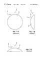
- a lens 2is substantially in a shape formed by cutting a part of a sphere. In the plan view, it is formed rotation-symmetrically, namely, in a round form, and in the front view and the side view, it is formed in a circular form.
- the lens 2is made of dielectric materials such as ceramics, resin, plastic, or their composite materials.
- the focal direction of the dielectric lens 1is the -z-axis direction.
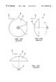
- FIGS. 12A, 12 B and 12 Cshow a dielectric lens antenna including the dielectric lens 1 shown in FIG. 11A, 11 B and 11 C.
- FIG. 12Ais a plan view;
- FIG. 12Bis a front view; and
- FIG. 12Cis a side view.
- the dielectric lens antenna 5is formed by disposing a primary radiator 7 at the focal point 6 of the dielectric lens 1 .
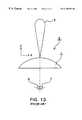
- FIG. 13shows a conceptual view (a front view) illustrating the directivity of a beam radiated from the dielectric lens 1 of the dielectric lens antenna 5 shown in FIGS. 12A, 12 B and 12 C.
- the same reference numeralsare given to the same parts as those in FIG. 12 or the equivalent parts to those in FIG. 12; their descriptions are omitted.
- the shape of beam 3 radiated from the dielectric lens 1 of the dielectric lens antenna 5is a pencil-beam shape on the x-z side.
- the length (the height in FIG. 13) of z-axis direction of the beam 3indicates the magnitude of a gain of the dielectric lens antenna 5
- the width of the beam 3indicates the magnitude of the beam width of the dielectric lens antenna 5 .
- the gain of the dielectric lens antenna 5amounts to a maximum value in the z-axis direction.
- the angle in which a gain decreases by 3 dB from the maximum valuenamely, the angle in which the gain amounts to a half is referred to a half-value angle, which indicates the directivity of the antenna.
- the shape of the beam 3 radiated from the dielectric lens 1 of the dielectric lens antenna 5is the same on all the sides which include the z-axis and parallel to the z-axis, such as the x-y side, so that the line connecting points of the half-value angles forms a round form when viewed from the front of the dielectric lens antenna 5 .
- the half-value angleis substantially indicated by a formula:
- a half-value angleis inversely proportional to an antenna aperture diameter.
- the wider the aperture diameterthe larger the gain.
- a motor-vehicle-mounted radardoes not necessarily require the information of a vertical direction (up-and-down directions) with respect to a traveling direction of a motor vehicle.
- a vertical directionup-and-down directions
- the information of a horizontal directionis primarily necessary, since other motor vehicles and obstacles are targeted. This can require a wide-angle antenna, in which a beam is narrowed in the vertical direction, whereas it is widened in the horizontal direction.
- preferred embodiments of the present inventionprovide a dielectric lens capable of widening a half-value angle in a specified direction without decreasing a gain significantly, a dielectric lens antenna including the same, and a wireless device including the same.
- One preferred embodiment of the present inventionprovides a dielectric lens and a dielectric lens antenna including the dielectric lens, wherein the dielectric lens is rotation-symmetrically shaped, and a flat end is disposed at a part of the edge the dielectric lens.
- a primary radiatoris disposed at the focal point of the dielectric lens.
- a first flat end and a second flat endare respectively disposed at a part of the edge the dielectric lens and opposed to each other.
- This structure and arrangementallows the half-value angles of the dielectric lens and the dielectric lens antenna to be smaller in the vertical direction (horizontal direction) and to be greater in the horizontal direction (vertical direction).
- the primary radiator and the dielectric lensmay be connected by a supporting plate extending in a taper shape from the outer periphery of the primary radiator to the edge of the dielectric lens over the entire circumference; and at least inner surface of the supporting plate may be made of metal.
- Another preferred embodiment of the present inventionprovides a wireless device comprising the above described dielectric lens antenna.
- Use of the dielectric lens antenna of the present inventioncan control extension of a beam to reduce malfunctions of a wireless device.
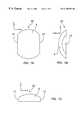
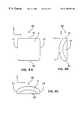
- FIGS. 1A, 1 B and 1 Cshow one preferred embodiment of a dielectric lens according to the present invention, in which FIG. 1A is a plan view; FIG. 1B is a front view; and FIG. 1C is a side view.
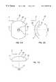
- FIGS. 2A, 2 B and 2 Cshow another preferred embodiment of a dielectric lens antenna according to the present invention, in which FIG. 2A is a plan view; FIG. 2B is a front view; and FIG. 2C is a side view.
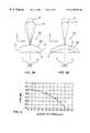
- FIGS. 3A and 3Bshow a conceptual view illustrating the directivity of a beam radiated from the dielectric lens of a dielectric lens antenna shown in FIGS. 2A, 2 B and 2 C, in which FIG. 3A is a front view; and FIG. 3B is a side view.
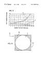
- FIG. 4shows a relationship between the amount of cut-away parts of the lens and gains of the dielectric lens antenna according to the present invention.
- FIG. 5shows a relationship between the amount of cut-away parts of the lens and half-value angles of the dielectric lens antenna according to the present invention.
- FIG. 6shows a plan view of the dead space in a state in which a conventional dielectric lens antenna is attached to a rectangular frame.
- FIG. 7shows a plan view of the dead space in a state in which the dielectric lens antenna of the present invention is attached to a rectangular frame.
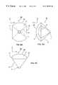
- FIGS. 8A, 8 B and 8 Cshow yet another preferred embodiment of the dielectric lens according to the present invention, in which FIG. 8A is a plan view; FIG. 8B is a front view; and FIG. 8C is a side view.
- FIGS. 9A, 9 B and 9 Cshow yet another preferred embodiment of the dielectric lens antenna according to the present invention, in which FIG. 9A is a plan view; FIG. 9B is a front view; and FIG. 9C is a side view.
- FIG. 10shows a block diagram of a preferred embodiment of a wireless device according to the present invention.
- FIGS. 11A, 11 B and 11 Cshow a view of a prior art dielectric lens, in which FIG. 11A is a plan view; FIG. 11B is a front view; and FIG. 11C is a side view.
- FIGS. 12A, 12 B and 12 Cshow a view of a prior art dielectric lens, in which FIG. 12A is a plan view; FIG. 12B is a front view; and FIG. 12C is a side view.
- FIG. 13shows a conceptual view (a front view) illustrating the directivity of a beam radiated from the dielectric lens of the dielectric lens antenna shown in FIGS. 12A, 12 B and 12 C.
- the left edge of the lens 2is linearly cut away from the rotation-symmetrical form, namely, the round form so as to make a flat first end 11 , whereas the right edge of the same is linearly cut away so as to make a flat second end 12 .
- the first end 11 and the second end 12are opposed to each other.
- the forming methodis not limited to the one in which the ends are formed by cutting away the edge after forming the lens rotation-symmetrically. It may be possible to form the lens in a shape having an end from the beginning.
- the dielectric lens antenna 15is formed by disposing a primary radiator 7 in the focal point 6 of the dielectric lens 10 .
- FIGS. 3A, 3 B and 3 Cshow a conceptual view illustrating the directivity of a beam 13 radiated from the dielectric lens 10 of the dielectric lens antenna 15 shown in FIG. 2 .
- the shape of the beam 3 radiated from the conventional dielectric lens antenna 5 shown in FIG. 13is indicated by dashed lines.
- the shape of the beam 13 radiated from the dielectric lens 10 of the dielectric lens antenna 15when compared to the shape of the conventional beam 3 , extends in the x-axis direction, namely, in a direction in which the first end 11 and the second end 12 are formed by cutting away the edge of the lens 2 ; thereby, a half-value angle widens.
- the maximum gainbecomes a little smaller than that of the conventional art, since the aperture area is reduced due to cutting-away of the edge of the lens. Meanwhile, as shown in FIG.
- the shape of the beam 13is substantially the same as that of the conventional one, although the maximum gain is smaller; and the half-value angle is almost the same.
- FIGS. 4 and 5respectively show the relationship between the amount of cut-away parts of the lens 2 and the antenna-gain, and the relationship between the amount of cut-away parts of the lens 2 and the half-value angle, respectively, in terms of the dielectric lens 10 used in the dielectric lens antenna 15 according to the present invention.
- the diameter of the lens 2is 73 mm.
- ashows a half-value angle on the x-z side and b shows a half-value angle on the y-z side.
- the larger the amount of cut-away parts of the lens 2the smaller the aperture area of the dielectric lens 10 ; thereby the gain tends to be smaller, too.
- the larger the amount of cut-away parts of the lens 2the exponentially wider the half-value angle a on the y-z side, namely, in the cut-away direction.
- the half-value angle b on the y-z sideis not influenced by the amount of cut-away parts of the lens 2 .
- the dielectric lens antenna 15is formed by using the dielectric lens 10 in such a manner that the x-axis direction is used as the horizontal direction and the y-axis direction is used as the vertical direction in FIGS. 2A, 2 B and 2 C. This permits formation of an antenna in which the beam does not extend in the horizontal direction, whereas it hardly extends in the vertical direction.
- the above-described dielectric lens antenna extending a beam in the horizontal directionis effective to a radar of mono-pulse system (a radar for measuring a distance and an angle with respect to a target by emitting a one-time-pulse signal in a wide range to receive a reflected signal by two or more antennas disposed mutually having a distance therebetween).
- a radar of beam-scan systema radar for measuring an angle with respect to a target by performing an action of measuring a distance to the target from a reflected signal by emitting a signal in a narrow range, while sequentially changing the angle of the antenna in the horizontal direction
- the vertical and horizontal directions in a plan view of the dielectric lens antenna shown in FIGS. 2A, 2 B and 2 Care inverted to use the x-axis direction vertically and the y-axis direction horizontally. This makes the beam toward the horizontal direction narrower; thereby malfunctions with respect to the angle of a target in beam-scanning can be reduced.
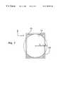
- FIG. 6shows a plan view of a prior art round dielectric lens 1 , which is attached to a rectangular frame 20 .
- a dead space 21a region which does not serve as the aperture face of the dielectric lens
- the area of the dead space 21 with respect to the frame 20is approximately 21.5%.
- FIG. 7shows a plan view of the dielectric lens 10 of the present invention, which is attached to a rectangular frame 22 .
- the dielectric lens 10originally has a rectangle shape substantially when viewed in the plan view, since the mutually opposing two places of the edge of the lens 2 are cut away to form the first end and the second end.
- the dead space 23 between the frame 22 and the dielectric lens 10can be formed to be smaller than the prior art dielectric lens 1 shown in FIG. 6 .
- the frame 22becomes a rectangle having two sides in the proportion of 3-to-4, and the area of the dead space 23 with respect to the frame 22 is approximately 10.4%, so that the area can be significantly smaller than that of the conventional art.
- a dielectric lens antennais mounted on the front of the vehicle, with the z-axis direction being oriented toward the direction in which the vehicle travels.
- the dead space of the dielectric lens antennais vertical to the traveling direction, air resistance increases and snow is likely to easily accumulate thereon.
- the dielectric lens antenna 10 of the present inventionthe smaller the area of the dead space, the smaller the air resistance and the less the accumulation of snow, so that degradation of antenna characteristics can be reduced.
- a third end 31in which the edge of the upper side of the lens 2 is linearly cut away to be flat, is formed, in addition to the first end 11 and the second end 12 formed on the dielectric lens 10 .
- a fourth end 32in which the edge of the lower side is linearly cut away to be flat, is formed.
- four places of the edge of the lens 2are cut away to form flat ends, respectively, so that the lens 2 is formed to be a shape close to a square when viewed in the plan view.
- Such an arrangementpermits the shape of a beam of the dielectric lens antenna using the dielectric lens 30 to be extended both in the horizontal direction and in the vertical direction. As a result, it is impossible to change the shape of a beam in the vertical direction and the horizontal direction as in the case of the dielectric lens antenna 15 shown in FIG. 2 .
- the dead space with respect to the rectangular frameis greatly smaller than that in the case where the diameter of the lens 2 is simply reduced. Accordingly, this can control both the reduction of the aperture area due to the miniaturization of the dielectric lens and the gain reduction so as to make both of them relatively small.
- the dead spaceis smaller than that of the dielectric lens 1 shown in FIG. 6, (namely, the aperture area is larger), so that a dielectric lens and a dielectric lens antenna having the same aperture diameter (namely, the same half-value angle) and yet offering a larger gain can be obtained.
- the dielectric lens antenna 40is formed in such a manner that the primary radiator 7 and the dielectric lens 10 in the dielectric lens antenna 15 shown in FIGS. 2A, 2 B and 2 C are connected by a supporting plate 41 extending in a taper shape over the entire circumference from the outer periphery of the primary radiator 7 to the edge of the dielectric lens 10 .
- the inner surface of the supporting plate 41is covered with metal coating to reflect electromagnetic waves.
- Forming the dielectric lens antenna 40 in this waycan reduce losses (spillover losses) due to electromagnetic waves leaking before reaching the dielectric lens 10 from the primary radiator 7 , which are the losses increased due to formation of flat ends by cutting away the edge of the lens 2 .
- Reduction of spillover lossesleads to achievement of high efficiency, so that miniaturization of the aperture area of the dielectric lens, namely, miniaturization of the dielectric lens antenna can be achieved.
- retaining of the primary radiator 7 and the dielectric lens 10 by the supporting plate 41permits the positional relationship between the primary radiator 7 and the dielectric lens 10 to be stable so as to reduce changes in the antenna characteristics with respect to vibrations or shocks, for instance, a positional deviation of the primary radiator 7 with respect to the focal point of the dielectric lens 10 .
- the dielectric lens antenna 40 shown in FIGS. 9A, 9 B and 9 Cadopts a supporting plate whose inner surface is coated with metal, it is possible to obtain similar advantages by sticking a metal plate onto the inner surface or by using a supporting plate whose entire part is made of metal.
- the two or four places of the edge of the lensare cut away to form flat ends.
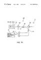
- FIG. 10shows a block diagram of a motor-vehicle-mounted millimeter-wave radar.
- a millimeter-wave radar 50is composed of the dielectric lens antenna 15 shown in FIGS. 2A, 2 B and 2 C, an oscillator 51 , circulators 52 and 53 , a mixer 54 , couplers 55 and 56 , and a signal-processing circuit 57 .
- the oscillator 51uses Gunn diode as an oscillation device and uses varactor diode as an oscillation-frequency control device to form a voltage-controlled oscillator.
- Bias voltage for Gunn diode and frequency-modulation control voltage VCO-INare input to the oscillator 51 ; and a transmission signal as the output is input to the coupler 55 through the circulator 52 so as not to return a reflection signal.
- the coupler 55divides the transmission signal into two to emit one of them from the dielectric lens antenna 15 through the circulator 53 and inputs the other one as a local signal to the circulator 56 . Meanwhile, the signal received by the dielectric lens antenna 15 is input to the coupler 56 through the circulator 53 .
- the coupler 56acts as a 3 dB-directional coupler to divide the local signal sent from the coupler 55 into equal parts with a phase difference of 90 degrees so as to input two mixer circuits of the mixer 54 , whereas the coupler also divides the received signal sent from the circulator 53 into equal parts with a phase difference of 90 degrees so as to input to the two mixer circuits of the mixer 54 .
- the mixer 54performs balance-mixing of the two signals in which the local signal and the received signal are mixed and outputs the frequency-difference component of the local signal and the received signal as an IF signal so as to input to the signal processing circuit 57 .
- the above millimeter-wave radar 50can obtain distance information and relative velocity information from the IF signal with the signal-processing circuit 57 , for example, by providing a triangular wave information as the above VCO-IN signal. Accordingly, when this is mounted in a motor vehicle, the relative distance and the relative velocity with respect to other vehicles can be measured. Moreover, use of the dielectric lens antenna according to the present invention permits reduction of malfunctions by extending or narrowing a beam in a specified direction.
Landscapes
- Aerials With Secondary Devices (AREA)
Abstract
Description
1. Field of the Invention
The present invention relates to a dielectric lens, a dielectric lens antenna including the same, and a wireless device including the same. More specifically, the present invention relates to a dielectric lens applied for a motor-vehicle-mounted radar which uses millimeter-waves, a dielectric lens antenna including the same, and a wireless device including the same.
2. Description of the Related Art
With the recent advance of motor-vehicle-mounted radar, control of the directivity of an antenna has been a significant concern.
FIGS. 11A,11B and11C show a prior art dielectric lens. FIG. 11A is a plan view, FIG. 11B is a front view, and FIG. 11C is a side view. In adielectric lens 1, alens 2 is substantially in a shape formed by cutting a part of a sphere. In the plan view, it is formed rotation-symmetrically, namely, in a round form, and in the front view and the side view, it is formed in a circular form. Thelens 2 is made of dielectric materials such as ceramics, resin, plastic, or their composite materials. The focal direction of thedielectric lens 1 is the -z-axis direction.
FIGS. 12A,12B and12C show a dielectric lens antenna including thedielectric lens 1 shown in FIG. 11A,11B and11C. FIG. 12A is a plan view; FIG. 12B is a front view; and FIG. 12C is a side view. In FIG. 12, thedielectric lens antenna 5 is formed by disposing aprimary radiator 7 at thefocal point 6 of thedielectric lens 1.
FIG. 13 shows a conceptual view (a front view) illustrating the directivity of a beam radiated from thedielectric lens 1 of thedielectric lens antenna 5 shown in FIGS. 12A,12B and12C. In FIG. 13, the same reference numerals are given to the same parts as those in FIG. 12 or the equivalent parts to those in FIG. 12; their descriptions are omitted. As shown in FIG. 13, the shape ofbeam 3 radiated from thedielectric lens 1 of thedielectric lens antenna 5 is a pencil-beam shape on the x-z side. In this case, the length (the height in FIG. 13) of z-axis direction of thebeam 3 indicates the magnitude of a gain of thedielectric lens antenna 5, and the width of thebeam 3 indicates the magnitude of the beam width of thedielectric lens antenna 5.
As seen above, the gain of thedielectric lens antenna 5 amounts to a maximum value in the z-axis direction. With respect to the z-axis direction, the angle in which a gain decreases by 3 dB from the maximum value, namely, the angle in which the gain amounts to a half is referred to a half-value angle, which indicates the directivity of the antenna. The shape of thebeam 3 radiated from thedielectric lens 1 of thedielectric lens antenna 5 is the same on all the sides which include the z-axis and parallel to the z-axis, such as the x-y side, so that the line connecting points of the half-value angles forms a round form when viewed from the front of thedielectric lens antenna 5. In addition, the half-value angle is substantially indicated by a formula:
(λ: wavelength of the used frequency,
D: antenna-aperture diameter)
Thus, a half-value angle is inversely proportional to an antenna aperture diameter. In contrast, the wider the aperture diameter, the larger the gain.
A motor-vehicle-mounted radar does not necessarily require the information of a vertical direction (up-and-down directions) with respect to a traveling direction of a motor vehicle. On the contrary, in order to prevent malfunctions due to reactions with a pedestrian overpass or a viaduct, it may be better for the radar to have less information of a vertical direction. Meanwhile, the information of a horizontal direction (a traveling direction and right-and-left directions of a motor vehicle) is primarily necessary, since other motor vehicles and obstacles are targeted. This can require a wide-angle antenna, in which a beam is narrowed in the vertical direction, whereas it is widened in the horizontal direction. In this case, in order to widen the beam, namely, to widen the half-value angle, it is necessary to make the antenna-aperture diameter smaller, namely, it is necessary to reduce the diameter of the dielectric lens. However, reducing the diameter of the dielectric lens leads to decrease in gain, thereby it creates a problem in which the lens can only detect at close range when it is used in radar. In addition, reducing the diameter of the dielectric lens leads to extension of the beam not only in the horizontal direction but also in the vertical direction; it thereby leads to further decrease in the gain in the horizontal direction.
To overcome the above problems, preferred embodiments of the present invention provide a dielectric lens capable of widening a half-value angle in a specified direction without decreasing a gain significantly, a dielectric lens antenna including the same, and a wireless device including the same.
One preferred embodiment of the present invention provides a dielectric lens and a dielectric lens antenna including the dielectric lens, wherein the dielectric lens is rotation-symmetrically shaped, and a flat end is disposed at a part of the edge the dielectric lens. In the dielectric lens antenna, a primary radiator is disposed at the focal point of the dielectric lens.
By the above described structure and arrangement, it become possible to widen a half-value angle in the direction in which the flat ends of the lens are disposed without reducing a gain significantly.
Preferably, in the above described dielectric lens, a first flat end and a second flat end are respectively disposed at a part of the edge the dielectric lens and opposed to each other. This structure and arrangement allows the half-value angles of the dielectric lens and the dielectric lens antenna to be smaller in the vertical direction (horizontal direction) and to be greater in the horizontal direction (vertical direction).
In the above described dielectric lens antenna, the primary radiator and the dielectric lens may be connected by a supporting plate extending in a taper shape from the outer periphery of the primary radiator to the edge of the dielectric lens over the entire circumference; and at least inner surface of the supporting plate may be made of metal.
By the above described structure and arrangement, spillover losses can be reduced to thereby high efficiency is achieved.
Another preferred embodiment of the present invention provides a wireless device comprising the above described dielectric lens antenna.
Use of the dielectric lens antenna of the present invention can control extension of a beam to reduce malfunctions of a wireless device.
Other features and advantages of the present invention will become apparent from the following description of preferred embodiments of the invention which refers to the accompanying drawings, wherein like reference numerals indicate like elements to avoid duplicative description.
FIGS. 1A,1B and1C show one preferred embodiment of a dielectric lens according to the present invention, in which FIG. 1A is a plan view; FIG. 1B is a front view; and FIG. 1C is a side view.
FIGS. 2A,2B and2C show another preferred embodiment of a dielectric lens antenna according to the present invention, in which FIG. 2A is a plan view; FIG. 2B is a front view; and FIG. 2C is a side view.
FIGS. 3A and 3B show a conceptual view illustrating the directivity of a beam radiated from the dielectric lens of a dielectric lens antenna shown in FIGS. 2A,2B and2C, in which FIG. 3A is a front view; and FIG. 3B is a side view.
FIG. 4 shows a relationship between the amount of cut-away parts of the lens and gains of the dielectric lens antenna according to the present invention.
FIG. 5 shows a relationship between the amount of cut-away parts of the lens and half-value angles of the dielectric lens antenna according to the present invention.
FIG. 6 shows a plan view of the dead space in a state in which a conventional dielectric lens antenna is attached to a rectangular frame.
FIG. 7 shows a plan view of the dead space in a state in which the dielectric lens antenna of the present invention is attached to a rectangular frame.
FIGS. 8A,8B and8C show yet another preferred embodiment of the dielectric lens according to the present invention, in which FIG. 8A is a plan view; FIG. 8B is a front view; and FIG. 8C is a side view.
FIGS. 9A,9B and9C show yet another preferred embodiment of the dielectric lens antenna according to the present invention, in which FIG. 9A is a plan view; FIG. 9B is a front view; and FIG. 9C is a side view.
FIG. 10 shows a block diagram of a preferred embodiment of a wireless device according to the present invention.
FIGS. 11A,11B and11C show a view of a prior art dielectric lens, in which FIG. 11A is a plan view; FIG. 11B is a front view; and FIG. 11C is a side view.
FIGS. 12A,12B and12C show a view of a prior art dielectric lens, in which FIG. 12A is a plan view; FIG. 12B is a front view; and FIG. 12C is a side view.
FIG. 13 shows a conceptual view (a front view) illustrating the directivity of a beam radiated from the dielectric lens of the dielectric lens antenna shown in FIGS. 12A,12B and12C.
Regarding adielectric lens 10 shown in FIGS. 1A,1B and1C, when compared to a prior art dielectric lens shown in FIG. 11A, the left edge of thelens 2 is linearly cut away from the rotation-symmetrical form, namely, the round form so as to make a flatfirst end 11, whereas the right edge of the same is linearly cut away so as to make a flatsecond end 12. Thefirst end 11 and thesecond end 12 are opposed to each other.
In terms of the formation of thefirst end 11 and thesecond end 12, for the sake of convenience, a description has been provided that they are formed by cutting away the edge of thelens 2. In addition, even in the hereinafter description, the expression of cutting away the edge of the lens will be used for the convenience. However, when the lens is actually formed, the forming method is not limited to the one in which the ends are formed by cutting away the edge after forming the lens rotation-symmetrically. It may be possible to form the lens in a shape having an end from the beginning.
Referring to FIGS. 2A,2B and2C, thedielectric lens antenna 15 is formed by disposing aprimary radiator 7 in thefocal point 6 of thedielectric lens 10.
FIGS. 3A,3B and3C show a conceptual view illustrating the directivity of abeam 13 radiated from thedielectric lens 10 of thedielectric lens antenna 15 shown in FIG.2. For comparison, the shape of thebeam 3 radiated from the conventionaldielectric lens antenna 5 shown in FIG. 13 is indicated by dashed lines.
As shown in FIG. 3A, the shape of thebeam 13 radiated from thedielectric lens 10 of thedielectric lens antenna 15, when compared to the shape of theconventional beam 3, extends in the x-axis direction, namely, in a direction in which thefirst end 11 and thesecond end 12 are formed by cutting away the edge of thelens 2; thereby, a half-value angle widens. In contrast, the maximum gain becomes a little smaller than that of the conventional art, since the aperture area is reduced due to cutting-away of the edge of the lens. Meanwhile, as shown in FIG. 3B, in the y-axis direction, namely, in the direction in which the edge of the lens is not cut away, the shape of thebeam 13 is substantially the same as that of the conventional one, although the maximum gain is smaller; and the half-value angle is almost the same.
FIGS. 4 and 5 respectively show the relationship between the amount of cut-away parts of thelens 2 and the antenna-gain, and the relationship between the amount of cut-away parts of thelens 2 and the half-value angle, respectively, in terms of thedielectric lens 10 used in thedielectric lens antenna 15 according to the present invention. In this case, the diameter of thelens 2 is 73 mm. In FIG. 5, a shows a half-value angle on the x-z side and b shows a half-value angle on the y-z side.
As shown in FIG. 4, the larger the amount of cut-away parts of thelens 2, the smaller the aperture area of thedielectric lens 10; thereby the gain tends to be smaller, too. In addition, as shown in FIG. 5, the larger the amount of cut-away parts of thelens 2, the exponentially wider the half-value angle a on the y-z side, namely, in the cut-away direction. The half-value angle b on the y-z side is not influenced by the amount of cut-away parts of thelens 2.
In this way, in thedielectric lens 10, it is to be understood that formation of thefirst end 11 and thesecond end 12 by cutting away mutually opposing two places of the edge of thelens 2 permits extension of a beam only in the direction in which the edge has been cut away. Furthermore, thedielectric lens antenna 15 is formed by using thedielectric lens 10 in such a manner that the x-axis direction is used as the horizontal direction and the y-axis direction is used as the vertical direction in FIGS. 2A,2B and2C. This permits formation of an antenna in which the beam does not extend in the horizontal direction, whereas it hardly extends in the vertical direction.
The above-described dielectric lens antenna extending a beam in the horizontal direction is effective to a radar of mono-pulse system (a radar for measuring a distance and an angle with respect to a target by emitting a one-time-pulse signal in a wide range to receive a reflected signal by two or more antennas disposed mutually having a distance therebetween). However, it is more convenient for a radar of beam-scan system (a radar for measuring an angle with respect to a target by performing an action of measuring a distance to the target from a reflected signal by emitting a signal in a narrow range, while sequentially changing the angle of the antenna in the horizontal direction) to make a beam in the horizontal direction narrower. Thus, in such a case, the vertical and horizontal directions in a plan view of the dielectric lens antenna shown in FIGS. 2A,2B and2C are inverted to use the x-axis direction vertically and the y-axis direction horizontally. This makes the beam toward the horizontal direction narrower; thereby malfunctions with respect to the angle of a target in beam-scanning can be reduced.
Generally, a dielectric lens is often attached to a rectangular frame. FIG. 6 shows a plan view of a prior art rounddielectric lens 1, which is attached to arectangular frame 20. As seen in FIG. 6, attaching the rounddielectric lens 1 to therectangular frame 20 allows a dead space21 (a region which does not serve as the aperture face of the dielectric lens) to be produced between theframe 20 and thedielectric lens 1 when view from the front. In this case, the area of thedead space 21 with respect to theframe 20 is approximately 21.5%.
Meanwhile, FIG. 7 shows a plan view of thedielectric lens 10 of the present invention, which is attached to arectangular frame 22. As seen in FIG. 7, thedielectric lens 10 originally has a rectangle shape substantially when viewed in the plan view, since the mutually opposing two places of the edge of thelens 2 are cut away to form the first end and the second end. When thedielectric lens 10 is attached to therectangular frame 22, thedead space 23 between theframe 22 and thedielectric lens 10 can be formed to be smaller than the priorart dielectric lens 1 shown in FIG.6. For example, if the mutually opposing two places of the edge of thelens 2 are cut away at the position of ¼ of the radius, respectively, to form the first end and the second end, theframe 22 becomes a rectangle having two sides in the proportion of 3-to-4, and the area of thedead space 23 with respect to theframe 22 is approximately 10.4%, so that the area can be significantly smaller than that of the conventional art.
Furthermore, in a motor-vehicle-mounted radar, a dielectric lens antenna is mounted on the front of the vehicle, with the z-axis direction being oriented toward the direction in which the vehicle travels. In this case, since the dead space of the dielectric lens antenna is vertical to the traveling direction, air resistance increases and snow is likely to easily accumulate thereon. In this point, according to thedielectric lens antenna 10 of the present invention, the smaller the area of the dead space, the smaller the air resistance and the less the accumulation of snow, so that degradation of antenna characteristics can be reduced.
Referring to FIGS. 8A,8B and8C, in thedielectric lens 30, athird end 31, in which the edge of the upper side of thelens 2 is linearly cut away to be flat, is formed, in addition to thefirst end 11 and thesecond end 12 formed on thedielectric lens 10. Whereas afourth end 32, in which the edge of the lower side is linearly cut away to be flat, is formed. In other words, four places of the edge of thelens 2 are cut away to form flat ends, respectively, so that thelens 2 is formed to be a shape close to a square when viewed in the plan view.
Such an arrangement permits the shape of a beam of the dielectric lens antenna using thedielectric lens 30 to be extended both in the horizontal direction and in the vertical direction. As a result, it is impossible to change the shape of a beam in the vertical direction and the horizontal direction as in the case of thedielectric lens antenna 15 shown in FIG.2. However, although it is not shown here, it is clear that the dead space with respect to the rectangular frame is greatly smaller than that in the case where the diameter of thelens 2 is simply reduced. Accordingly, this can control both the reduction of the aperture area due to the miniaturization of the dielectric lens and the gain reduction so as to make both of them relatively small.
In contrast, when the diameter of thelens 2 of thedielectric lens 30 is extended to be as long as a diagonal line of theframe 20 shown in FIG. 6, and then the four places of the edge are cut away so as to be contained in theframe 20, the dead space is smaller than that of thedielectric lens 1 shown in FIG. 6, (namely, the aperture area is larger), so that a dielectric lens and a dielectric lens antenna having the same aperture diameter (namely, the same half-value angle) and yet offering a larger gain can be obtained.
Referring to FIGS. 9A,9B and9C, thedielectric lens antenna 40 is formed in such a manner that theprimary radiator 7 and thedielectric lens 10 in thedielectric lens antenna 15 shown in FIGS. 2A,2B and2C are connected by a supportingplate 41 extending in a taper shape over the entire circumference from the outer periphery of theprimary radiator 7 to the edge of thedielectric lens 10. In this case, the inner surface of the supportingplate 41 is covered with metal coating to reflect electromagnetic waves.
Forming thedielectric lens antenna 40 in this way can reduce losses (spillover losses) due to electromagnetic waves leaking before reaching thedielectric lens 10 from theprimary radiator 7, which are the losses increased due to formation of flat ends by cutting away the edge of thelens 2. Reduction of spillover losses leads to achievement of high efficiency, so that miniaturization of the aperture area of the dielectric lens, namely, miniaturization of the dielectric lens antenna can be achieved. Furthermore, retaining of theprimary radiator 7 and thedielectric lens 10 by the supportingplate 41 permits the positional relationship between theprimary radiator 7 and thedielectric lens 10 to be stable so as to reduce changes in the antenna characteristics with respect to vibrations or shocks, for instance, a positional deviation of theprimary radiator 7 with respect to the focal point of thedielectric lens 10.
Although thedielectric lens antenna 40 shown in FIGS. 9A,9B and9C adopts a supporting plate whose inner surface is coated with metal, it is possible to obtain similar advantages by sticking a metal plate onto the inner surface or by using a supporting plate whose entire part is made of metal.
In addition, in the above embodiments, the two or four places of the edge of the lens are cut away to form flat ends. However, it may be possible to adopt an arrangement in which one, three, five or more places of the edge are cut away to form flat ends so as to obtain similar advantages.
As a preferred embodiment of a wireless device according to the present invention, FIG. 10 shows a block diagram of a motor-vehicle-mounted millimeter-wave radar. In FIG. 10, a millimeter-wave radar 50 is composed of thedielectric lens antenna 15 shown in FIGS. 2A,2B and2C, anoscillator 51,circulators mixer 54,couplers processing circuit 57.
In the millimeter-wave radar 50 having such an arrangement, theoscillator 51 uses Gunn diode as an oscillation device and uses varactor diode as an oscillation-frequency control device to form a voltage-controlled oscillator. Bias voltage for Gunn diode and frequency-modulation control voltage VCO-IN are input to theoscillator 51; and a transmission signal as the output is input to thecoupler 55 through thecirculator 52 so as not to return a reflection signal. Thecoupler 55 divides the transmission signal into two to emit one of them from thedielectric lens antenna 15 through thecirculator 53 and inputs the other one as a local signal to thecirculator 56. Meanwhile, the signal received by thedielectric lens antenna 15 is input to thecoupler 56 through thecirculator 53. Thecoupler 56 acts as a 3 dB-directional coupler to divide the local signal sent from thecoupler 55 into equal parts with a phase difference of 90 degrees so as to input two mixer circuits of themixer 54, whereas the coupler also divides the received signal sent from thecirculator 53 into equal parts with a phase difference of 90 degrees so as to input to the two mixer circuits of themixer 54. Themixer 54 performs balance-mixing of the two signals in which the local signal and the received signal are mixed and outputs the frequency-difference component of the local signal and the received signal as an IF signal so as to input to thesignal processing circuit 57.
The above millimeter-wave radar 50 can obtain distance information and relative velocity information from the IF signal with the signal-processing circuit 57, for example, by providing a triangular wave information as the above VCO-IN signal. Accordingly, when this is mounted in a motor vehicle, the relative distance and the relative velocity with respect to other vehicles can be measured. Moreover, use of the dielectric lens antenna according to the present invention permits reduction of malfunctions by extending or narrowing a beam in a specified direction.
While the invention has been particularly shown and described with reference to preferred embodiments thereof, it will be understood by those skilled in the art that the forgoing and other changes in form and details may be made therein without departing from the spirit of the invention.
Claims (10)
1. A dielectric lens comprising a rotation-symmetrically shaped body having a perimeter edge portion; and
at least one flat part disposed at a part only of the perimeter edge portion.
2. The dielectric lens according to claim1, wherein a first flat part and a second flat part are respectively disposed at a part of the perimeter edge portion of the dielectric lens and opposed to each other.
3. The dielectric lens antenna comprising a dielectric lens having a rotation-symmetrically shaped body having a perimeter edge portion and at least one flat part disposed at a part only of the perimeter edge portion and a primary radiator disposed at a focal point of the dielectric lens.
4. A dielectric lens antenna comprising a dielectric lens having a rotation-symmetrically shaped body having a perimeter edge portion and wherein a first flat part and a second flat part are respectively disposed at a part of the perimeter edge portion of the dielectric lens and opposed to each other, and further comprising a primary radiator disposed at a focal point of the dielectric lens.
5. The dielectric lens antenna according to claim3, wherein the primary radiator and the dielectric lens are connected by a supporting plate extending in a taper shape for the outer periphery of the primary radiator to the edge portion of the dielectric lens over the entire circumference; and
at least an inner surface of the supporting plate is made of metal.
6. The dielectric lens antenna according to claim5, wherein the primary radiator and the dielectric lens are connected by a supporting plate extending in a taper shape from the outer periphery of the primary radiator to the edge portion of the dielectric lens over the entire circumference; and
at least an inner surface of the supporting plate is made of metal.
7. A wireless device comprising a dielectric lens antenna comprising a dielectric lens having a rotation-symmetrically shaped body having a perimeter edge portion and at least one flat part disposed at a part only of the perimeter edge portion and further comprising a primary radiator disposed at a focal point of the dielectric lens.
8. A wireless device comprising a dielectric lens antenna comprising a dielectric lens having a rotation-symmetrically shaped body having a perimeter edge portion and a primary radiator disposed at a focal point of the dielectric lens and further comprising a first flat part and a second flat part respectively disposed at a part of the edge portion of the dielectric lens and opposed to each other.
9. A wireless device comprising a dielectric lens antenna comprising a dielectric lens having a rotation-symmetrically shaped body having a perimeter edge portion and at least one flat part disposed at a part only of the perimeter edge portion and further comprising a primary radiator disposed at a focal point of the dielectric lens and further wherein the primary radiator and the dielectric lens are connected by a supporting plate extending in a taper shape from the outer periphery of the primary radiator to the edge portion of the dielectric lens over the entire circumference; and
at least an inner surface of the supporting plate is made of metal.
10. A wireless device comprising a dielectric lens antenna comprising a dielectric lens having a rotation-symmetrically shaped body having a perimeter edge portion and wherein a first flat part and a second flat part are respectively disposed at a part of the perimeter edge portion of the dielectric lens and opposed to each other, and further comprising a primary radiator disposed at a focal point of the dielectric lens; and further wherein the primary radiator and the dielectric lens are connected by a supporting plate extending in a taper shape from the outer periphery of the primary radiator to the edge portion of the dielectric lens over the entire circumference; and
at least an inner surface of the supporting plate is made of metal.
Applications Claiming Priority (2)
| Application Number | Priority Date | Filing Date | Title |
|---|---|---|---|
| JP10-182525 | 1998-06-29 | ||
| JP18252598AJP3650952B2 (en) | 1998-06-29 | 1998-06-29 | Dielectric lens, dielectric lens antenna using the same, and radio apparatus using the same |
Publications (1)
| Publication Number | Publication Date |
|---|---|
| US6195058B1true US6195058B1 (en) | 2001-02-27 |
Family
ID=16119839
Family Applications (1)
| Application Number | Title | Priority Date | Filing Date |
|---|---|---|---|
| US09/340,615Expired - LifetimeUS6195058B1 (en) | 1998-06-29 | 1999-06-29 | Dielectric lens, dielectric lens antenna including the same, and wireless device using the same |
Country Status (3)
| Country | Link |
|---|---|
| US (1) | US6195058B1 (en) |
| EP (1) | EP0969549A1 (en) |
| JP (1) | JP3650952B2 (en) |
Cited By (167)
| Publication number | Priority date | Publication date | Assignee | Title |
|---|---|---|---|---|
| US6433751B1 (en)* | 1999-02-12 | 2002-08-13 | Tdk Corporation | Lens antenna and lens antenna array |
| US20030011533A1 (en)* | 2001-07-04 | 2003-01-16 | Kiyoyasu Sakurada | Lens antenna |
| US20050179606A1 (en)* | 2004-02-16 | 2005-08-18 | The Boeing Company | Focal plane array for thz imager and associated methods |
| US20050190101A1 (en)* | 2004-02-26 | 2005-09-01 | Kyocera Corporation | Transmitting/receiving antenna, isolator, high-frequency oscillator, and high-frequency transmitter-receiver using the same |
| US20080180336A1 (en)* | 2007-01-31 | 2008-07-31 | Bauregger Frank N | Lensed antenna methods and systems for navigation or other signals |
| US20150287895A1 (en)* | 2011-04-22 | 2015-10-08 | Micron Technology, Inc. | Solid state lighting devices having improved color uniformity and associated methods |
| US9525210B2 (en) | 2014-10-21 | 2016-12-20 | At&T Intellectual Property I, L.P. | Guided-wave transmission device with non-fundamental mode propagation and methods for use therewith |
| US9544006B2 (en) | 2014-11-20 | 2017-01-10 | At&T Intellectual Property I, L.P. | Transmission device with mode division multiplexing and methods for use therewith |
| US20170018856A1 (en)* | 2015-07-15 | 2017-01-19 | At&T Intellectual Property I, Lp | Antenna system with dielectric array and methods for use therewith |
| US9577307B2 (en) | 2014-10-21 | 2017-02-21 | At&T Intellectual Property I, L.P. | Guided-wave transmission device and methods for use therewith |
| US9596001B2 (en) | 2014-10-21 | 2017-03-14 | At&T Intellectual Property I, L.P. | Apparatus for providing communication services and methods thereof |
| US9608740B2 (en) | 2015-07-15 | 2017-03-28 | At&T Intellectual Property I, L.P. | Method and apparatus for launching a wave mode that mitigates interference |
| US9608692B2 (en) | 2015-06-11 | 2017-03-28 | At&T Intellectual Property I, L.P. | Repeater and methods for use therewith |
| US9615269B2 (en) | 2014-10-02 | 2017-04-04 | At&T Intellectual Property I, L.P. | Method and apparatus that provides fault tolerance in a communication network |
| US9628854B2 (en) | 2014-09-29 | 2017-04-18 | At&T Intellectual Property I, L.P. | Method and apparatus for distributing content in a communication network |
| US9628116B2 (en) | 2015-07-14 | 2017-04-18 | At&T Intellectual Property I, L.P. | Apparatus and methods for transmitting wireless signals |
| US9640850B2 (en) | 2015-06-25 | 2017-05-02 | At&T Intellectual Property I, L.P. | Methods and apparatus for inducing a non-fundamental wave mode on a transmission medium |
| US9654173B2 (en) | 2014-11-20 | 2017-05-16 | At&T Intellectual Property I, L.P. | Apparatus for powering a communication device and methods thereof |
| US9653770B2 (en) | 2014-10-21 | 2017-05-16 | At&T Intellectual Property I, L.P. | Guided wave coupler, coupling module and methods for use therewith |
| US9661505B2 (en) | 2013-11-06 | 2017-05-23 | At&T Intellectual Property I, L.P. | Surface-wave communications and methods thereof |
| US9667317B2 (en) | 2015-06-15 | 2017-05-30 | At&T Intellectual Property I, L.P. | Method and apparatus for providing security using network traffic adjustments |
| US9685992B2 (en) | 2014-10-03 | 2017-06-20 | At&T Intellectual Property I, L.P. | Circuit panel network and methods thereof |
| US9692101B2 (en) | 2014-08-26 | 2017-06-27 | At&T Intellectual Property I, L.P. | Guided wave couplers for coupling electromagnetic waves between a waveguide surface and a surface of a wire |
| US9699785B2 (en) | 2012-12-05 | 2017-07-04 | At&T Intellectual Property I, L.P. | Backhaul link for distributed antenna system |
| US9705561B2 (en) | 2015-04-24 | 2017-07-11 | At&T Intellectual Property I, L.P. | Directional coupling device and methods for use therewith |
| US9705610B2 (en) | 2014-10-21 | 2017-07-11 | At&T Intellectual Property I, L.P. | Transmission device with impairment compensation and methods for use therewith |
| US9712350B2 (en) | 2014-11-20 | 2017-07-18 | At&T Intellectual Property I, L.P. | Transmission device with channel equalization and control and methods for use therewith |
| US9722318B2 (en) | 2015-07-14 | 2017-08-01 | At&T Intellectual Property I, L.P. | Method and apparatus for coupling an antenna to a device |
| US9729197B2 (en) | 2015-10-01 | 2017-08-08 | At&T Intellectual Property I, L.P. | Method and apparatus for communicating network management traffic over a network |
| US9735833B2 (en) | 2015-07-31 | 2017-08-15 | At&T Intellectual Property I, L.P. | Method and apparatus for communications management in a neighborhood network |
| US9742462B2 (en) | 2014-12-04 | 2017-08-22 | At&T Intellectual Property I, L.P. | Transmission medium and communication interfaces and methods for use therewith |
| US9749013B2 (en) | 2015-03-17 | 2017-08-29 | At&T Intellectual Property I, L.P. | Method and apparatus for reducing attenuation of electromagnetic waves guided by a transmission medium |
| US9748626B2 (en) | 2015-05-14 | 2017-08-29 | At&T Intellectual Property I, L.P. | Plurality of cables having different cross-sectional shapes which are bundled together to form a transmission medium |
| US9749053B2 (en) | 2015-07-23 | 2017-08-29 | At&T Intellectual Property I, L.P. | Node device, repeater and methods for use therewith |
| US9762289B2 (en) | 2014-10-14 | 2017-09-12 | At&T Intellectual Property I, L.P. | Method and apparatus for transmitting or receiving signals in a transportation system |
| US9769128B2 (en) | 2015-09-28 | 2017-09-19 | At&T Intellectual Property I, L.P. | Method and apparatus for encryption of communications over a network |
| US9768833B2 (en) | 2014-09-15 | 2017-09-19 | At&T Intellectual Property I, L.P. | Method and apparatus for sensing a condition in a transmission medium of electromagnetic waves |
| US9769020B2 (en) | 2014-10-21 | 2017-09-19 | At&T Intellectual Property I, L.P. | Method and apparatus for responding to events affecting communications in a communication network |
| US20170279202A1 (en)* | 2016-03-25 | 2017-09-28 | Commscope Technologies Llc | Antennas having lenses formed of lightweight dielectric materials and related dielectric materials |
| US9780834B2 (en) | 2014-10-21 | 2017-10-03 | At&T Intellectual Property I, L.P. | Method and apparatus for transmitting electromagnetic waves |
| US9787412B2 (en) | 2015-06-25 | 2017-10-10 | At&T Intellectual Property I, L.P. | Methods and apparatus for inducing a fundamental wave mode on a transmission medium |
| US9793954B2 (en) | 2015-04-28 | 2017-10-17 | At&T Intellectual Property I, L.P. | Magnetic coupling device and methods for use therewith |
| US9793951B2 (en) | 2015-07-15 | 2017-10-17 | At&T Intellectual Property I, L.P. | Method and apparatus for launching a wave mode that mitigates interference |
| US9794003B2 (en) | 2013-12-10 | 2017-10-17 | At&T Intellectual Property I, L.P. | Quasi-optical coupler |
| US9793955B2 (en) | 2015-04-24 | 2017-10-17 | At&T Intellectual Property I, Lp | Passive electrical coupling device and methods for use therewith |
| US9800327B2 (en) | 2014-11-20 | 2017-10-24 | At&T Intellectual Property I, L.P. | Apparatus for controlling operations of a communication device and methods thereof |
| US9820146B2 (en) | 2015-06-12 | 2017-11-14 | At&T Intellectual Property I, L.P. | Method and apparatus for authentication and identity management of communicating devices |
| US9838896B1 (en) | 2016-12-09 | 2017-12-05 | At&T Intellectual Property I, L.P. | Method and apparatus for assessing network coverage |
| US9836957B2 (en) | 2015-07-14 | 2017-12-05 | At&T Intellectual Property I, L.P. | Method and apparatus for communicating with premises equipment |
| US9838078B2 (en) | 2015-07-31 | 2017-12-05 | At&T Intellectual Property I, L.P. | Method and apparatus for exchanging communication signals |
| US9847566B2 (en) | 2015-07-14 | 2017-12-19 | At&T Intellectual Property I, L.P. | Method and apparatus for adjusting a field of a signal to mitigate interference |
| US9847850B2 (en) | 2014-10-14 | 2017-12-19 | At&T Intellectual Property I, L.P. | Method and apparatus for adjusting a mode of communication in a communication network |
| US9853342B2 (en) | 2015-07-14 | 2017-12-26 | At&T Intellectual Property I, L.P. | Dielectric transmission medium connector and methods for use therewith |
| US9860075B1 (en) | 2016-08-26 | 2018-01-02 | At&T Intellectual Property I, L.P. | Method and communication node for broadband distribution |
| US9866276B2 (en) | 2014-10-10 | 2018-01-09 | At&T Intellectual Property I, L.P. | Method and apparatus for arranging communication sessions in a communication system |
| US9865911B2 (en) | 2015-06-25 | 2018-01-09 | At&T Intellectual Property I, L.P. | Waveguide system for slot radiating first electromagnetic waves that are combined into a non-fundamental wave mode second electromagnetic wave on a transmission medium |
| US9866309B2 (en) | 2015-06-03 | 2018-01-09 | At&T Intellectual Property I, Lp | Host node device and methods for use therewith |
| US9871282B2 (en) | 2015-05-14 | 2018-01-16 | At&T Intellectual Property I, L.P. | At least one transmission medium having a dielectric surface that is covered at least in part by a second dielectric |
| US9871283B2 (en) | 2015-07-23 | 2018-01-16 | At&T Intellectual Property I, Lp | Transmission medium having a dielectric core comprised of plural members connected by a ball and socket configuration |
| US9876571B2 (en) | 2015-02-20 | 2018-01-23 | At&T Intellectual Property I, Lp | Guided-wave transmission device with non-fundamental mode propagation and methods for use therewith |
| US9876605B1 (en) | 2016-10-21 | 2018-01-23 | At&T Intellectual Property I, L.P. | Launcher and coupling system to support desired guided wave mode |
| US9876264B2 (en) | 2015-10-02 | 2018-01-23 | At&T Intellectual Property I, Lp | Communication system, guided wave switch and methods for use therewith |
| US9882257B2 (en) | 2015-07-14 | 2018-01-30 | At&T Intellectual Property I, L.P. | Method and apparatus for launching a wave mode that mitigates interference |
| US9882277B2 (en) | 2015-10-02 | 2018-01-30 | At&T Intellectual Property I, Lp | Communication device and antenna assembly with actuated gimbal mount |
| US9887447B2 (en) | 2015-05-14 | 2018-02-06 | At&T Intellectual Property I, L.P. | Transmission medium having multiple cores and methods for use therewith |
| US9893795B1 (en) | 2016-12-07 | 2018-02-13 | At&T Intellectual Property I, Lp | Method and repeater for broadband distribution |
| US9904535B2 (en) | 2015-09-14 | 2018-02-27 | At&T Intellectual Property I, L.P. | Method and apparatus for distributing software |
| US9906269B2 (en) | 2014-09-17 | 2018-02-27 | At&T Intellectual Property I, L.P. | Monitoring and mitigating conditions in a communication network |
| US9912419B1 (en) | 2016-08-24 | 2018-03-06 | At&T Intellectual Property I, L.P. | Method and apparatus for managing a fault in a distributed antenna system |
| US9912027B2 (en) | 2015-07-23 | 2018-03-06 | At&T Intellectual Property I, L.P. | Method and apparatus for exchanging communication signals |
| US9912381B2 (en) | 2015-06-03 | 2018-03-06 | At&T Intellectual Property I, Lp | Network termination and methods for use therewith |
| US9911020B1 (en) | 2016-12-08 | 2018-03-06 | At&T Intellectual Property I, L.P. | Method and apparatus for tracking via a radio frequency identification device |
| US9913139B2 (en) | 2015-06-09 | 2018-03-06 | At&T Intellectual Property I, L.P. | Signal fingerprinting for authentication of communicating devices |
| US9917341B2 (en) | 2015-05-27 | 2018-03-13 | At&T Intellectual Property I, L.P. | Apparatus and method for launching electromagnetic waves and for modifying radial dimensions of the propagating electromagnetic waves |
| US9930668B2 (en) | 2013-05-31 | 2018-03-27 | At&T Intellectual Property I, L.P. | Remote distributed antenna system |
| US9927517B1 (en) | 2016-12-06 | 2018-03-27 | At&T Intellectual Property I, L.P. | Apparatus and methods for sensing rainfall |
| US9948333B2 (en) | 2015-07-23 | 2018-04-17 | At&T Intellectual Property I, L.P. | Method and apparatus for wireless communications to mitigate interference |
| US9948354B2 (en) | 2015-04-28 | 2018-04-17 | At&T Intellectual Property I, L.P. | Magnetic coupling device with reflective plate and methods for use therewith |
| US9954287B2 (en) | 2014-11-20 | 2018-04-24 | At&T Intellectual Property I, L.P. | Apparatus for converting wireless signals and electromagnetic waves and methods thereof |
| US9967173B2 (en) | 2015-07-31 | 2018-05-08 | At&T Intellectual Property I, L.P. | Method and apparatus for authentication and identity management of communicating devices |
| US9973940B1 (en) | 2017-02-27 | 2018-05-15 | At&T Intellectual Property I, L.P. | Apparatus and methods for dynamic impedance matching of a guided wave launcher |
| US9991580B2 (en) | 2016-10-21 | 2018-06-05 | At&T Intellectual Property I, L.P. | Launcher and coupling system for guided wave mode cancellation |
| US9998870B1 (en) | 2016-12-08 | 2018-06-12 | At&T Intellectual Property I, L.P. | Method and apparatus for proximity sensing |
| US9999038B2 (en) | 2013-05-31 | 2018-06-12 | At&T Intellectual Property I, L.P. | Remote distributed antenna system |
| US9997819B2 (en) | 2015-06-09 | 2018-06-12 | At&T Intellectual Property I, L.P. | Transmission medium and method for facilitating propagation of electromagnetic waves via a core |
| US10009065B2 (en) | 2012-12-05 | 2018-06-26 | At&T Intellectual Property I, L.P. | Backhaul link for distributed antenna system |
| US10009067B2 (en) | 2014-12-04 | 2018-06-26 | At&T Intellectual Property I, L.P. | Method and apparatus for configuring a communication interface |
| US10009063B2 (en) | 2015-09-16 | 2018-06-26 | At&T Intellectual Property I, L.P. | Method and apparatus for use with a radio distributed antenna system having an out-of-band reference signal |
| US10009901B2 (en) | 2015-09-16 | 2018-06-26 | At&T Intellectual Property I, L.P. | Method, apparatus, and computer-readable storage medium for managing utilization of wireless resources between base stations |
| US10020587B2 (en) | 2015-07-31 | 2018-07-10 | At&T Intellectual Property I, L.P. | Radial antenna and methods for use therewith |
| US10020844B2 (en) | 2016-12-06 | 2018-07-10 | T&T Intellectual Property I, L.P. | Method and apparatus for broadcast communication via guided waves |
| US10027397B2 (en) | 2016-12-07 | 2018-07-17 | At&T Intellectual Property I, L.P. | Distributed antenna system and methods for use therewith |
| US10033108B2 (en) | 2015-07-14 | 2018-07-24 | At&T Intellectual Property I, L.P. | Apparatus and methods for generating an electromagnetic wave having a wave mode that mitigates interference |
| US10033107B2 (en) | 2015-07-14 | 2018-07-24 | At&T Intellectual Property I, L.P. | Method and apparatus for coupling an antenna to a device |
| US10044409B2 (en) | 2015-07-14 | 2018-08-07 | At&T Intellectual Property I, L.P. | Transmission medium and methods for use therewith |
| US10051629B2 (en) | 2015-09-16 | 2018-08-14 | At&T Intellectual Property I, L.P. | Method and apparatus for use with a radio distributed antenna system having an in-band reference signal |
| US10069535B2 (en) | 2016-12-08 | 2018-09-04 | At&T Intellectual Property I, L.P. | Apparatus and methods for launching electromagnetic waves having a certain electric field structure |
| US10079661B2 (en) | 2015-09-16 | 2018-09-18 | At&T Intellectual Property I, L.P. | Method and apparatus for use with a radio distributed antenna system having a clock reference |
| US10090594B2 (en) | 2016-11-23 | 2018-10-02 | At&T Intellectual Property I, L.P. | Antenna system having structural configurations for assembly |
| US10103422B2 (en) | 2016-12-08 | 2018-10-16 | At&T Intellectual Property I, L.P. | Method and apparatus for mounting network devices |
| US10103801B2 (en) | 2015-06-03 | 2018-10-16 | At&T Intellectual Property I, L.P. | Host node device and methods for use therewith |
| US10136434B2 (en) | 2015-09-16 | 2018-11-20 | At&T Intellectual Property I, L.P. | Method and apparatus for use with a radio distributed antenna system having an ultra-wideband control channel |
| US10135145B2 (en) | 2016-12-06 | 2018-11-20 | At&T Intellectual Property I, L.P. | Apparatus and methods for generating an electromagnetic wave along a transmission medium |
| US10135146B2 (en) | 2016-10-18 | 2018-11-20 | At&T Intellectual Property I, L.P. | Apparatus and methods for launching guided waves via circuits |
| US10135147B2 (en) | 2016-10-18 | 2018-11-20 | At&T Intellectual Property I, L.P. | Apparatus and methods for launching guided waves via an antenna |
| US10142086B2 (en) | 2015-06-11 | 2018-11-27 | At&T Intellectual Property I, L.P. | Repeater and methods for use therewith |
| US10139820B2 (en) | 2016-12-07 | 2018-11-27 | At&T Intellectual Property I, L.P. | Method and apparatus for deploying equipment of a communication system |
| US10144036B2 (en) | 2015-01-30 | 2018-12-04 | At&T Intellectual Property I, L.P. | Method and apparatus for mitigating interference affecting a propagation of electromagnetic waves guided by a transmission medium |
| US10148016B2 (en) | 2015-07-14 | 2018-12-04 | At&T Intellectual Property I, L.P. | Apparatus and methods for communicating utilizing an antenna array |
| US10168695B2 (en) | 2016-12-07 | 2019-01-01 | At&T Intellectual Property I, L.P. | Method and apparatus for controlling an unmanned aircraft |
| US10170840B2 (en) | 2015-07-14 | 2019-01-01 | At&T Intellectual Property I, L.P. | Apparatus and methods for sending or receiving electromagnetic signals |
| US10178445B2 (en) | 2016-11-23 | 2019-01-08 | At&T Intellectual Property I, L.P. | Methods, devices, and systems for load balancing between a plurality of waveguides |
| US10205655B2 (en) | 2015-07-14 | 2019-02-12 | At&T Intellectual Property I, L.P. | Apparatus and methods for communicating utilizing an antenna array and multiple communication paths |
| US10224634B2 (en) | 2016-11-03 | 2019-03-05 | At&T Intellectual Property I, L.P. | Methods and apparatus for adjusting an operational characteristic of an antenna |
| US10225025B2 (en) | 2016-11-03 | 2019-03-05 | At&T Intellectual Property I, L.P. | Method and apparatus for detecting a fault in a communication system |
| US10243270B2 (en) | 2016-12-07 | 2019-03-26 | At&T Intellectual Property I, L.P. | Beam adaptive multi-feed dielectric antenna system and methods for use therewith |
| US10243784B2 (en) | 2014-11-20 | 2019-03-26 | At&T Intellectual Property I, L.P. | System for generating topology information and methods thereof |
| US10264586B2 (en) | 2016-12-09 | 2019-04-16 | At&T Mobility Ii Llc | Cloud-based packet controller and methods for use therewith |
| US10291311B2 (en) | 2016-09-09 | 2019-05-14 | At&T Intellectual Property I, L.P. | Method and apparatus for mitigating a fault in a distributed antenna system |
| US10291334B2 (en) | 2016-11-03 | 2019-05-14 | At&T Intellectual Property I, L.P. | System for detecting a fault in a communication system |
| US10298293B2 (en) | 2017-03-13 | 2019-05-21 | At&T Intellectual Property I, L.P. | Apparatus of communication utilizing wireless network devices |
| US10305190B2 (en) | 2016-12-01 | 2019-05-28 | At&T Intellectual Property I, L.P. | Reflecting dielectric antenna system and methods for use therewith |
| US10312567B2 (en) | 2016-10-26 | 2019-06-04 | At&T Intellectual Property I, L.P. | Launcher with planar strip antenna and methods for use therewith |
| US10320586B2 (en) | 2015-07-14 | 2019-06-11 | At&T Intellectual Property I, L.P. | Apparatus and methods for generating non-interfering electromagnetic waves on an insulated transmission medium |
| US10326689B2 (en) | 2016-12-08 | 2019-06-18 | At&T Intellectual Property I, L.P. | Method and system for providing alternative communication paths |
| US10326494B2 (en) | 2016-12-06 | 2019-06-18 | At&T Intellectual Property I, L.P. | Apparatus for measurement de-embedding and methods for use therewith |
| US10340983B2 (en) | 2016-12-09 | 2019-07-02 | At&T Intellectual Property I, L.P. | Method and apparatus for surveying remote sites via guided wave communications |
| US10340601B2 (en) | 2016-11-23 | 2019-07-02 | At&T Intellectual Property I, L.P. | Multi-antenna system and methods for use therewith |
| US10340600B2 (en) | 2016-10-18 | 2019-07-02 | At&T Intellectual Property I, L.P. | Apparatus and methods for launching guided waves via plural waveguide systems |
| US10340603B2 (en) | 2016-11-23 | 2019-07-02 | At&T Intellectual Property I, L.P. | Antenna system having shielded structural configurations for assembly |
| US10341142B2 (en) | 2015-07-14 | 2019-07-02 | At&T Intellectual Property I, L.P. | Apparatus and methods for generating non-interfering electromagnetic waves on an uninsulated conductor |
| US10340573B2 (en) | 2016-10-26 | 2019-07-02 | At&T Intellectual Property I, L.P. | Launcher with cylindrical coupling device and methods for use therewith |
| US10355367B2 (en) | 2015-10-16 | 2019-07-16 | At&T Intellectual Property I, L.P. | Antenna structure for exchanging wireless signals |
| US10361489B2 (en) | 2016-12-01 | 2019-07-23 | At&T Intellectual Property I, L.P. | Dielectric dish antenna system and methods for use therewith |
| US10359749B2 (en) | 2016-12-07 | 2019-07-23 | At&T Intellectual Property I, L.P. | Method and apparatus for utilities management via guided wave communication |
| US10374316B2 (en) | 2016-10-21 | 2019-08-06 | At&T Intellectual Property I, L.P. | System and dielectric antenna with non-uniform dielectric |
| US10382976B2 (en) | 2016-12-06 | 2019-08-13 | At&T Intellectual Property I, L.P. | Method and apparatus for managing wireless communications based on communication paths and network device positions |
| US10389029B2 (en) | 2016-12-07 | 2019-08-20 | At&T Intellectual Property I, L.P. | Multi-feed dielectric antenna system with core selection and methods for use therewith |
| US10389037B2 (en) | 2016-12-08 | 2019-08-20 | At&T Intellectual Property I, L.P. | Apparatus and methods for selecting sections of an antenna array and use therewith |
| CN110165403A (en)* | 2019-06-10 | 2019-08-23 | 电子科技大学 | Hemisphere dielectric lens antenna is deformed based on array-fed large-angle scanning |
| US10411356B2 (en) | 2016-12-08 | 2019-09-10 | At&T Intellectual Property I, L.P. | Apparatus and methods for selectively targeting communication devices with an antenna array |
| US10439675B2 (en) | 2016-12-06 | 2019-10-08 | At&T Intellectual Property I, L.P. | Method and apparatus for repeating guided wave communication signals |
| US10446936B2 (en) | 2016-12-07 | 2019-10-15 | At&T Intellectual Property I, L.P. | Multi-feed dielectric antenna system and methods for use therewith |
| US10498044B2 (en) | 2016-11-03 | 2019-12-03 | At&T Intellectual Property I, L.P. | Apparatus for configuring a surface of an antenna |
| US10530505B2 (en) | 2016-12-08 | 2020-01-07 | At&T Intellectual Property I, L.P. | Apparatus and methods for launching electromagnetic waves along a transmission medium |
| US10535928B2 (en) | 2016-11-23 | 2020-01-14 | At&T Intellectual Property I, L.P. | Antenna system and methods for use therewith |
| US10547348B2 (en) | 2016-12-07 | 2020-01-28 | At&T Intellectual Property I, L.P. | Method and apparatus for switching transmission mediums in a communication system |
| US10601494B2 (en) | 2016-12-08 | 2020-03-24 | At&T Intellectual Property I, L.P. | Dual-band communication device and method for use therewith |
| US10637149B2 (en) | 2016-12-06 | 2020-04-28 | At&T Intellectual Property I, L.P. | Injection molded dielectric antenna and methods for use therewith |
| US10650940B2 (en) | 2015-05-15 | 2020-05-12 | At&T Intellectual Property I, L.P. | Transmission medium having a conductive material and methods for use therewith |
| US10665942B2 (en) | 2015-10-16 | 2020-05-26 | At&T Intellectual Property I, L.P. | Method and apparatus for adjusting wireless communications |
| US10694379B2 (en) | 2016-12-06 | 2020-06-23 | At&T Intellectual Property I, L.P. | Waveguide system with device-based authentication and methods for use therewith |
| US10727599B2 (en) | 2016-12-06 | 2020-07-28 | At&T Intellectual Property I, L.P. | Launcher with slot antenna and methods for use therewith |
| CN111566875A (en)* | 2017-12-29 | 2020-08-21 | 华为技术有限公司 | a device |
| US10755542B2 (en) | 2016-12-06 | 2020-08-25 | At&T Intellectual Property I, L.P. | Method and apparatus for surveillance via guided wave communication |
| US10777873B2 (en) | 2016-12-08 | 2020-09-15 | At&T Intellectual Property I, L.P. | Method and apparatus for mounting network devices |
| US10784670B2 (en) | 2015-07-23 | 2020-09-22 | At&T Intellectual Property I, L.P. | Antenna support for aligning an antenna |
| US10797781B2 (en) | 2015-06-03 | 2020-10-06 | At&T Intellectual Property I, L.P. | Client node device and methods for use therewith |
| US10811767B2 (en) | 2016-10-21 | 2020-10-20 | At&T Intellectual Property I, L.P. | System and dielectric antenna with convex dielectric radome |
| US10819035B2 (en) | 2016-12-06 | 2020-10-27 | At&T Intellectual Property I, L.P. | Launcher with helical antenna and methods for use therewith |
| US10916969B2 (en) | 2016-12-08 | 2021-02-09 | At&T Intellectual Property I, L.P. | Method and apparatus for providing power using an inductive coupling |
| US10938108B2 (en) | 2016-12-08 | 2021-03-02 | At&T Intellectual Property I, L.P. | Frequency selective multi-feed dielectric antenna system and methods for use therewith |
| US11032819B2 (en) | 2016-09-15 | 2021-06-08 | At&T Intellectual Property I, L.P. | Method and apparatus for use with a radio distributed antenna system having a control channel reference signal |
| US11431100B2 (en) | 2016-03-25 | 2022-08-30 | Commscope Technologies Llc | Antennas having lenses formed of lightweight dielectric materials and related dielectric materials |
| US11527835B2 (en) | 2017-09-15 | 2022-12-13 | Commscope Technologies Llc | Methods of preparing a composite dielectric material |
| US20240055772A1 (en)* | 2020-12-02 | 2024-02-15 | Telefonaktiebolaget Lm Ericsson (Publ) | Lens antenna, lens antenna array, radio device and method performed by radio device |
| US20240222879A1 (en)* | 2023-01-04 | 2024-07-04 | Enplas Corporation | Communication module and electromagnetic flux controlling member used for the same |
Families Citing this family (3)
| Publication number | Priority date | Publication date | Assignee | Title |
|---|---|---|---|---|
| RU2214658C1 (en)* | 2002-03-20 | 2003-10-20 | 16 Центральный научно-исследовательский испытательный институт Министерства обороны Российской Федерации | Antenna with controllable dome-shaped lens |
| US7301504B2 (en) | 2004-07-14 | 2007-11-27 | Ems Technologies, Inc. | Mechanical scanning feed assembly for a spherical lens antenna |
| CN112688086B (en)* | 2020-11-27 | 2023-01-24 | 中国电波传播研究所(中国电子科技集团公司第二十二研究所) | Dual-polarized integrated lens antenna |
Citations (11)
| Publication number | Priority date | Publication date | Assignee | Title |
|---|---|---|---|---|
| FR2423876A1 (en) | 1978-04-17 | 1979-11-16 | Antennes Moulees Plastiques | Aerial for repeaters or transmitter-receiver stations - has dielectric lens and is covered with silicon dielectric layer for protection against nuclear explosion heat radiation |
| GB2029114A (en) | 1978-08-25 | 1980-03-12 | Plessey Inc | Dielectric lens |
| US4307403A (en)* | 1979-06-26 | 1981-12-22 | Nippon Telegraph & Telephone Public Corp. | Aperture antenna having the improved cross-polarization performance |
| US4825221A (en)* | 1985-01-16 | 1989-04-25 | Junkosha Co., Ltd. | Directly emitting dielectric transmission line |
| DE3840451A1 (en) | 1988-12-01 | 1990-06-07 | Telefunken Systemtechnik | Lens antenna |
| WO1998015033A1 (en) | 1996-09-30 | 1998-04-09 | Qualcomm Incorporated | Dielectric lens assembly for a feed antenna |
| DE19645816A1 (en) | 1996-11-07 | 1998-05-14 | Bosch Gmbh Robert | Lens arrangement for bundling radar waves |
| US5892487A (en)* | 1993-02-28 | 1999-04-06 | Thomson Multimedia S.A. | Antenna system |
| US5900847A (en)* | 1996-01-18 | 1999-05-04 | Murata Manufacturing Co., Ltd. | Dielectric lens apparatus |
| US6034642A (en)* | 1996-11-01 | 2000-03-07 | Honda Giken Kogyo Kabushiki Kaisha | Antenna apparatus |
| US6052087A (en)* | 1997-04-10 | 2000-04-18 | Murata Manufacturing Co., Ltd. | Antenna device and radar module |
Family Cites Families (9)
| Publication number | Priority date | Publication date | Assignee | Title |
|---|---|---|---|---|
| US3576577A (en) | 1968-06-05 | 1971-04-27 | Lignes Telegraph Telephon | Aerial radiating with different beamwidth in two perpendicular planes |
| JPH0720011B2 (en)* | 1986-07-28 | 1995-03-06 | 沖電気工業株式会社 | Circular polarization modified beam antenna |
| JPH02288404A (en)* | 1989-04-27 | 1990-11-28 | Murata Mfg Co Ltd | Antenna equipment |
| JPH0361811A (en)* | 1989-07-31 | 1991-03-18 | Canon Inc | distance measuring device |
| JP2898862B2 (en)* | 1993-10-13 | 1999-06-02 | オプテックス株式会社 | Object detection sensor using dielectric lens |
| JPH0933703A (en)* | 1995-07-18 | 1997-02-07 | Taiho Kogyo Kk | lens |
| JPH09218257A (en)* | 1996-02-15 | 1997-08-19 | Toyota Motor Corp | In-vehicle radar device |
| DE19642810C1 (en)* | 1996-10-17 | 1998-04-02 | Bosch Gmbh Robert | Directional radar system for anticollision and vehicle speed measurement |
| JP3786497B2 (en)* | 1997-06-13 | 2006-06-14 | 富士通株式会社 | Semiconductor module with built-in antenna element |
- 1998
- 1998-06-29JPJP18252598Apatent/JP3650952B2/ennot_activeExpired - Fee Related
- 1999
- 1999-06-15EPEP99111604Apatent/EP0969549A1/ennot_activeWithdrawn
- 1999-06-29USUS09/340,615patent/US6195058B1/ennot_activeExpired - Lifetime
Patent Citations (11)
| Publication number | Priority date | Publication date | Assignee | Title |
|---|---|---|---|---|
| FR2423876A1 (en) | 1978-04-17 | 1979-11-16 | Antennes Moulees Plastiques | Aerial for repeaters or transmitter-receiver stations - has dielectric lens and is covered with silicon dielectric layer for protection against nuclear explosion heat radiation |
| GB2029114A (en) | 1978-08-25 | 1980-03-12 | Plessey Inc | Dielectric lens |
| US4307403A (en)* | 1979-06-26 | 1981-12-22 | Nippon Telegraph & Telephone Public Corp. | Aperture antenna having the improved cross-polarization performance |
| US4825221A (en)* | 1985-01-16 | 1989-04-25 | Junkosha Co., Ltd. | Directly emitting dielectric transmission line |
| DE3840451A1 (en) | 1988-12-01 | 1990-06-07 | Telefunken Systemtechnik | Lens antenna |
| US5892487A (en)* | 1993-02-28 | 1999-04-06 | Thomson Multimedia S.A. | Antenna system |
| US5900847A (en)* | 1996-01-18 | 1999-05-04 | Murata Manufacturing Co., Ltd. | Dielectric lens apparatus |
| WO1998015033A1 (en) | 1996-09-30 | 1998-04-09 | Qualcomm Incorporated | Dielectric lens assembly for a feed antenna |
| US6034642A (en)* | 1996-11-01 | 2000-03-07 | Honda Giken Kogyo Kabushiki Kaisha | Antenna apparatus |
| DE19645816A1 (en) | 1996-11-07 | 1998-05-14 | Bosch Gmbh Robert | Lens arrangement for bundling radar waves |
| US6052087A (en)* | 1997-04-10 | 2000-04-18 | Murata Manufacturing Co., Ltd. | Antenna device and radar module |
Cited By (219)
| Publication number | Priority date | Publication date | Assignee | Title |
|---|---|---|---|---|
| US6433751B1 (en)* | 1999-02-12 | 2002-08-13 | Tdk Corporation | Lens antenna and lens antenna array |
| US20030011533A1 (en)* | 2001-07-04 | 2003-01-16 | Kiyoyasu Sakurada | Lens antenna |
| US7088309B2 (en)* | 2001-07-04 | 2006-08-08 | Murata Manufacturing Co., Ltd. | Lens antenna |
| US20050179606A1 (en)* | 2004-02-16 | 2005-08-18 | The Boeing Company | Focal plane array for thz imager and associated methods |
| US6943742B2 (en)* | 2004-02-16 | 2005-09-13 | The Boeing Company | Focal plane array for THz imager and associated methods |
| US20050190101A1 (en)* | 2004-02-26 | 2005-09-01 | Kyocera Corporation | Transmitting/receiving antenna, isolator, high-frequency oscillator, and high-frequency transmitter-receiver using the same |
| US7602333B2 (en)* | 2004-02-26 | 2009-10-13 | Kyocera Corporation | Transmitting/receiving antenna, isolator, high-frequency oscillator, and high-frequency transmitter-receiver using the same |
| US20080180336A1 (en)* | 2007-01-31 | 2008-07-31 | Bauregger Frank N | Lensed antenna methods and systems for navigation or other signals |
| US10243120B2 (en) | 2011-04-22 | 2019-03-26 | Micron Technology, Inc. | Solid state lighting devices having improved color uniformity and associated methods |
| US10002994B2 (en)* | 2011-04-22 | 2018-06-19 | Micron Technology, Inc. | Solid state lighting devices having improved color uniformity and associated methods |
| US10804447B2 (en) | 2011-04-22 | 2020-10-13 | Micron Technology, Inc. | Solid state lighting devices having improved color uniformity and associated methods |
| US20150287895A1 (en)* | 2011-04-22 | 2015-10-08 | Micron Technology, Inc. | Solid state lighting devices having improved color uniformity and associated methods |
| US9788326B2 (en) | 2012-12-05 | 2017-10-10 | At&T Intellectual Property I, L.P. | Backhaul link for distributed antenna system |
| US9699785B2 (en) | 2012-12-05 | 2017-07-04 | At&T Intellectual Property I, L.P. | Backhaul link for distributed antenna system |
| US10009065B2 (en) | 2012-12-05 | 2018-06-26 | At&T Intellectual Property I, L.P. | Backhaul link for distributed antenna system |
| US10194437B2 (en) | 2012-12-05 | 2019-01-29 | At&T Intellectual Property I, L.P. | Backhaul link for distributed antenna system |
| US10091787B2 (en) | 2013-05-31 | 2018-10-02 | At&T Intellectual Property I, L.P. | Remote distributed antenna system |
| US9999038B2 (en) | 2013-05-31 | 2018-06-12 | At&T Intellectual Property I, L.P. | Remote distributed antenna system |
| US9930668B2 (en) | 2013-05-31 | 2018-03-27 | At&T Intellectual Property I, L.P. | Remote distributed antenna system |
| US10051630B2 (en) | 2013-05-31 | 2018-08-14 | At&T Intellectual Property I, L.P. | Remote distributed antenna system |
| US9661505B2 (en) | 2013-11-06 | 2017-05-23 | At&T Intellectual Property I, L.P. | Surface-wave communications and methods thereof |
| US9876584B2 (en) | 2013-12-10 | 2018-01-23 | At&T Intellectual Property I, L.P. | Quasi-optical coupler |
| US9794003B2 (en) | 2013-12-10 | 2017-10-17 | At&T Intellectual Property I, L.P. | Quasi-optical coupler |
| US10096881B2 (en) | 2014-08-26 | 2018-10-09 | At&T Intellectual Property I, L.P. | Guided wave couplers for coupling electromagnetic waves to an outer surface of a transmission medium |
| US9692101B2 (en) | 2014-08-26 | 2017-06-27 | At&T Intellectual Property I, L.P. | Guided wave couplers for coupling electromagnetic waves between a waveguide surface and a surface of a wire |
| US9768833B2 (en) | 2014-09-15 | 2017-09-19 | At&T Intellectual Property I, L.P. | Method and apparatus for sensing a condition in a transmission medium of electromagnetic waves |
| US10063280B2 (en) | 2014-09-17 | 2018-08-28 | At&T Intellectual Property I, L.P. | Monitoring and mitigating conditions in a communication network |
| US9906269B2 (en) | 2014-09-17 | 2018-02-27 | At&T Intellectual Property I, L.P. | Monitoring and mitigating conditions in a communication network |
| US9628854B2 (en) | 2014-09-29 | 2017-04-18 | At&T Intellectual Property I, L.P. | Method and apparatus for distributing content in a communication network |
| US9615269B2 (en) | 2014-10-02 | 2017-04-04 | At&T Intellectual Property I, L.P. | Method and apparatus that provides fault tolerance in a communication network |
| US9998932B2 (en) | 2014-10-02 | 2018-06-12 | At&T Intellectual Property I, L.P. | Method and apparatus that provides fault tolerance in a communication network |
| US9973416B2 (en) | 2014-10-02 | 2018-05-15 | At&T Intellectual Property I, L.P. | Method and apparatus that provides fault tolerance in a communication network |
| US9685992B2 (en) | 2014-10-03 | 2017-06-20 | At&T Intellectual Property I, L.P. | Circuit panel network and methods thereof |
| US9866276B2 (en) | 2014-10-10 | 2018-01-09 | At&T Intellectual Property I, L.P. | Method and apparatus for arranging communication sessions in a communication system |
| US9762289B2 (en) | 2014-10-14 | 2017-09-12 | At&T Intellectual Property I, L.P. | Method and apparatus for transmitting or receiving signals in a transportation system |
| US9847850B2 (en) | 2014-10-14 | 2017-12-19 | At&T Intellectual Property I, L.P. | Method and apparatus for adjusting a mode of communication in a communication network |
| US9973299B2 (en) | 2014-10-14 | 2018-05-15 | At&T Intellectual Property I, L.P. | Method and apparatus for adjusting a mode of communication in a communication network |
| US9653770B2 (en) | 2014-10-21 | 2017-05-16 | At&T Intellectual Property I, L.P. | Guided wave coupler, coupling module and methods for use therewith |
| US9912033B2 (en) | 2014-10-21 | 2018-03-06 | At&T Intellectual Property I, Lp | Guided wave coupler, coupling module and methods for use therewith |
| US9948355B2 (en) | 2014-10-21 | 2018-04-17 | At&T Intellectual Property I, L.P. | Apparatus for providing communication services and methods thereof |
| US9960808B2 (en) | 2014-10-21 | 2018-05-01 | At&T Intellectual Property I, L.P. | Guided-wave transmission device and methods for use therewith |
| US9871558B2 (en) | 2014-10-21 | 2018-01-16 | At&T Intellectual Property I, L.P. | Guided-wave transmission device and methods for use therewith |
| US9627768B2 (en) | 2014-10-21 | 2017-04-18 | At&T Intellectual Property I, L.P. | Guided-wave transmission device with non-fundamental mode propagation and methods for use therewith |
| US9876587B2 (en) | 2014-10-21 | 2018-01-23 | At&T Intellectual Property I, L.P. | Transmission device with impairment compensation and methods for use therewith |
| US9769020B2 (en) | 2014-10-21 | 2017-09-19 | At&T Intellectual Property I, L.P. | Method and apparatus for responding to events affecting communications in a communication network |
| US9525210B2 (en) | 2014-10-21 | 2016-12-20 | At&T Intellectual Property I, L.P. | Guided-wave transmission device with non-fundamental mode propagation and methods for use therewith |
| US9780834B2 (en) | 2014-10-21 | 2017-10-03 | At&T Intellectual Property I, L.P. | Method and apparatus for transmitting electromagnetic waves |
| US9705610B2 (en) | 2014-10-21 | 2017-07-11 | At&T Intellectual Property I, L.P. | Transmission device with impairment compensation and methods for use therewith |
| US9596001B2 (en) | 2014-10-21 | 2017-03-14 | At&T Intellectual Property I, L.P. | Apparatus for providing communication services and methods thereof |
| US9577306B2 (en) | 2014-10-21 | 2017-02-21 | At&T Intellectual Property I, L.P. | Guided-wave transmission device and methods for use therewith |
| US9577307B2 (en) | 2014-10-21 | 2017-02-21 | At&T Intellectual Property I, L.P. | Guided-wave transmission device and methods for use therewith |
| US9954286B2 (en) | 2014-10-21 | 2018-04-24 | At&T Intellectual Property I, L.P. | Guided-wave transmission device with non-fundamental mode propagation and methods for use therewith |
| US10243784B2 (en) | 2014-11-20 | 2019-03-26 | At&T Intellectual Property I, L.P. | System for generating topology information and methods thereof |
| US9654173B2 (en) | 2014-11-20 | 2017-05-16 | At&T Intellectual Property I, L.P. | Apparatus for powering a communication device and methods thereof |
| US9749083B2 (en) | 2014-11-20 | 2017-08-29 | At&T Intellectual Property I, L.P. | Transmission device with mode division multiplexing and methods for use therewith |
| US9800327B2 (en) | 2014-11-20 | 2017-10-24 | At&T Intellectual Property I, L.P. | Apparatus for controlling operations of a communication device and methods thereof |
| US9954287B2 (en) | 2014-11-20 | 2018-04-24 | At&T Intellectual Property I, L.P. | Apparatus for converting wireless signals and electromagnetic waves and methods thereof |
| US9544006B2 (en) | 2014-11-20 | 2017-01-10 | At&T Intellectual Property I, L.P. | Transmission device with mode division multiplexing and methods for use therewith |
| US9712350B2 (en) | 2014-11-20 | 2017-07-18 | At&T Intellectual Property I, L.P. | Transmission device with channel equalization and control and methods for use therewith |
| US9742521B2 (en) | 2014-11-20 | 2017-08-22 | At&T Intellectual Property I, L.P. | Transmission device with mode division multiplexing and methods for use therewith |
| US10009067B2 (en) | 2014-12-04 | 2018-06-26 | At&T Intellectual Property I, L.P. | Method and apparatus for configuring a communication interface |
| US9742462B2 (en) | 2014-12-04 | 2017-08-22 | At&T Intellectual Property I, L.P. | Transmission medium and communication interfaces and methods for use therewith |
| US10144036B2 (en) | 2015-01-30 | 2018-12-04 | At&T Intellectual Property I, L.P. | Method and apparatus for mitigating interference affecting a propagation of electromagnetic waves guided by a transmission medium |
| US9876570B2 (en) | 2015-02-20 | 2018-01-23 | At&T Intellectual Property I, Lp | Guided-wave transmission device with non-fundamental mode propagation and methods for use therewith |
| US9876571B2 (en) | 2015-02-20 | 2018-01-23 | At&T Intellectual Property I, Lp | Guided-wave transmission device with non-fundamental mode propagation and methods for use therewith |
| US9749013B2 (en) | 2015-03-17 | 2017-08-29 | At&T Intellectual Property I, L.P. | Method and apparatus for reducing attenuation of electromagnetic waves guided by a transmission medium |
| US10224981B2 (en) | 2015-04-24 | 2019-03-05 | At&T Intellectual Property I, Lp | Passive electrical coupling device and methods for use therewith |
| US9705561B2 (en) | 2015-04-24 | 2017-07-11 | At&T Intellectual Property I, L.P. | Directional coupling device and methods for use therewith |
| US9831912B2 (en) | 2015-04-24 | 2017-11-28 | At&T Intellectual Property I, Lp | Directional coupling device and methods for use therewith |
| US9793955B2 (en) | 2015-04-24 | 2017-10-17 | At&T Intellectual Property I, Lp | Passive electrical coupling device and methods for use therewith |
| US9793954B2 (en) | 2015-04-28 | 2017-10-17 | At&T Intellectual Property I, L.P. | Magnetic coupling device and methods for use therewith |
| US9948354B2 (en) | 2015-04-28 | 2018-04-17 | At&T Intellectual Property I, L.P. | Magnetic coupling device with reflective plate and methods for use therewith |
| US9887447B2 (en) | 2015-05-14 | 2018-02-06 | At&T Intellectual Property I, L.P. | Transmission medium having multiple cores and methods for use therewith |
| US9871282B2 (en) | 2015-05-14 | 2018-01-16 | At&T Intellectual Property I, L.P. | At least one transmission medium having a dielectric surface that is covered at least in part by a second dielectric |
| US9748626B2 (en) | 2015-05-14 | 2017-08-29 | At&T Intellectual Property I, L.P. | Plurality of cables having different cross-sectional shapes which are bundled together to form a transmission medium |
| US10650940B2 (en) | 2015-05-15 | 2020-05-12 | At&T Intellectual Property I, L.P. | Transmission medium having a conductive material and methods for use therewith |
| US9917341B2 (en) | 2015-05-27 | 2018-03-13 | At&T Intellectual Property I, L.P. | Apparatus and method for launching electromagnetic waves and for modifying radial dimensions of the propagating electromagnetic waves |
| US10050697B2 (en) | 2015-06-03 | 2018-08-14 | At&T Intellectual Property I, L.P. | Host node device and methods for use therewith |
| US9866309B2 (en) | 2015-06-03 | 2018-01-09 | At&T Intellectual Property I, Lp | Host node device and methods for use therewith |
| US10812174B2 (en) | 2015-06-03 | 2020-10-20 | At&T Intellectual Property I, L.P. | Client node device and methods for use therewith |
| US10797781B2 (en) | 2015-06-03 | 2020-10-06 | At&T Intellectual Property I, L.P. | Client node device and methods for use therewith |
| US9935703B2 (en) | 2015-06-03 | 2018-04-03 | At&T Intellectual Property I, L.P. | Host node device and methods for use therewith |
| US9967002B2 (en) | 2015-06-03 | 2018-05-08 | At&T Intellectual I, Lp | Network termination and methods for use therewith |
| US10103801B2 (en) | 2015-06-03 | 2018-10-16 | At&T Intellectual Property I, L.P. | Host node device and methods for use therewith |
| US9912382B2 (en) | 2015-06-03 | 2018-03-06 | At&T Intellectual Property I, Lp | Network termination and methods for use therewith |
| US9912381B2 (en) | 2015-06-03 | 2018-03-06 | At&T Intellectual Property I, Lp | Network termination and methods for use therewith |
| US9913139B2 (en) | 2015-06-09 | 2018-03-06 | At&T Intellectual Property I, L.P. | Signal fingerprinting for authentication of communicating devices |
| US9997819B2 (en) | 2015-06-09 | 2018-06-12 | At&T Intellectual Property I, L.P. | Transmission medium and method for facilitating propagation of electromagnetic waves via a core |
| US10142086B2 (en) | 2015-06-11 | 2018-11-27 | At&T Intellectual Property I, L.P. | Repeater and methods for use therewith |
| US10142010B2 (en) | 2015-06-11 | 2018-11-27 | At&T Intellectual Property I, L.P. | Repeater and methods for use therewith |
| US10027398B2 (en) | 2015-06-11 | 2018-07-17 | At&T Intellectual Property I, Lp | Repeater and methods for use therewith |
| US9608692B2 (en) | 2015-06-11 | 2017-03-28 | At&T Intellectual Property I, L.P. | Repeater and methods for use therewith |
| US9820146B2 (en) | 2015-06-12 | 2017-11-14 | At&T Intellectual Property I, L.P. | Method and apparatus for authentication and identity management of communicating devices |
| US9667317B2 (en) | 2015-06-15 | 2017-05-30 | At&T Intellectual Property I, L.P. | Method and apparatus for providing security using network traffic adjustments |
| US10069185B2 (en) | 2015-06-25 | 2018-09-04 | At&T Intellectual Property I, L.P. | Methods and apparatus for inducing a non-fundamental wave mode on a transmission medium |
| US10090601B2 (en) | 2015-06-25 | 2018-10-02 | At&T Intellectual Property I, L.P. | Waveguide system and methods for inducing a non-fundamental wave mode on a transmission medium |
| US9787412B2 (en) | 2015-06-25 | 2017-10-10 | At&T Intellectual Property I, L.P. | Methods and apparatus for inducing a fundamental wave mode on a transmission medium |
| US9640850B2 (en) | 2015-06-25 | 2017-05-02 | At&T Intellectual Property I, L.P. | Methods and apparatus for inducing a non-fundamental wave mode on a transmission medium |
| US9882657B2 (en) | 2015-06-25 | 2018-01-30 | At&T Intellectual Property I, L.P. | Methods and apparatus for inducing a fundamental wave mode on a transmission medium |
| US9865911B2 (en) | 2015-06-25 | 2018-01-09 | At&T Intellectual Property I, L.P. | Waveguide system for slot radiating first electromagnetic waves that are combined into a non-fundamental wave mode second electromagnetic wave on a transmission medium |
| US9882257B2 (en) | 2015-07-14 | 2018-01-30 | At&T Intellectual Property I, L.P. | Method and apparatus for launching a wave mode that mitigates interference |
| US10148016B2 (en) | 2015-07-14 | 2018-12-04 | At&T Intellectual Property I, L.P. | Apparatus and methods for communicating utilizing an antenna array |
| US10341142B2 (en) | 2015-07-14 | 2019-07-02 | At&T Intellectual Property I, L.P. | Apparatus and methods for generating non-interfering electromagnetic waves on an uninsulated conductor |
| US9836957B2 (en) | 2015-07-14 | 2017-12-05 | At&T Intellectual Property I, L.P. | Method and apparatus for communicating with premises equipment |
| US9929755B2 (en) | 2015-07-14 | 2018-03-27 | At&T Intellectual Property I, L.P. | Method and apparatus for coupling an antenna to a device |
| US9847566B2 (en) | 2015-07-14 | 2017-12-19 | At&T Intellectual Property I, L.P. | Method and apparatus for adjusting a field of a signal to mitigate interference |
| US10044409B2 (en) | 2015-07-14 | 2018-08-07 | At&T Intellectual Property I, L.P. | Transmission medium and methods for use therewith |
| US10033107B2 (en) | 2015-07-14 | 2018-07-24 | At&T Intellectual Property I, L.P. | Method and apparatus for coupling an antenna to a device |
| US10033108B2 (en) | 2015-07-14 | 2018-07-24 | At&T Intellectual Property I, L.P. | Apparatus and methods for generating an electromagnetic wave having a wave mode that mitigates interference |
| US9853342B2 (en) | 2015-07-14 | 2017-12-26 | At&T Intellectual Property I, L.P. | Dielectric transmission medium connector and methods for use therewith |
| US10205655B2 (en) | 2015-07-14 | 2019-02-12 | At&T Intellectual Property I, L.P. | Apparatus and methods for communicating utilizing an antenna array and multiple communication paths |
| US9628116B2 (en) | 2015-07-14 | 2017-04-18 | At&T Intellectual Property I, L.P. | Apparatus and methods for transmitting wireless signals |
| US10170840B2 (en) | 2015-07-14 | 2019-01-01 | At&T Intellectual Property I, L.P. | Apparatus and methods for sending or receiving electromagnetic signals |
| US9722318B2 (en) | 2015-07-14 | 2017-08-01 | At&T Intellectual Property I, L.P. | Method and apparatus for coupling an antenna to a device |
| US10320586B2 (en) | 2015-07-14 | 2019-06-11 | At&T Intellectual Property I, L.P. | Apparatus and methods for generating non-interfering electromagnetic waves on an insulated transmission medium |
| US9947982B2 (en) | 2015-07-14 | 2018-04-17 | At&T Intellectual Property I, Lp | Dielectric transmission medium connector and methods for use therewith |
| US9608740B2 (en) | 2015-07-15 | 2017-03-28 | At&T Intellectual Property I, L.P. | Method and apparatus for launching a wave mode that mitigates interference |
| US20170018856A1 (en)* | 2015-07-15 | 2017-01-19 | At&T Intellectual Property I, Lp | Antenna system with dielectric array and methods for use therewith |
| US10090606B2 (en)* | 2015-07-15 | 2018-10-02 | At&T Intellectual Property I, L.P. | Antenna system with dielectric array and methods for use therewith |
| US10916863B2 (en)* | 2015-07-15 | 2021-02-09 | At&T Intellectual Property I, L.P. | Antenna system with dielectric array and methods for use therewith |
| US9793951B2 (en) | 2015-07-15 | 2017-10-17 | At&T Intellectual Property I, L.P. | Method and apparatus for launching a wave mode that mitigates interference |
| US9806818B2 (en) | 2015-07-23 | 2017-10-31 | At&T Intellectual Property I, Lp | Node device, repeater and methods for use therewith |
| US9912027B2 (en) | 2015-07-23 | 2018-03-06 | At&T Intellectual Property I, L.P. | Method and apparatus for exchanging communication signals |
| US9871283B2 (en) | 2015-07-23 | 2018-01-16 | At&T Intellectual Property I, Lp | Transmission medium having a dielectric core comprised of plural members connected by a ball and socket configuration |
| US9948333B2 (en) | 2015-07-23 | 2018-04-17 | At&T Intellectual Property I, L.P. | Method and apparatus for wireless communications to mitigate interference |
| US10074886B2 (en) | 2015-07-23 | 2018-09-11 | At&T Intellectual Property I, L.P. | Dielectric transmission medium comprising a plurality of rigid dielectric members coupled together in a ball and socket configuration |
| US9749053B2 (en) | 2015-07-23 | 2017-08-29 | At&T Intellectual Property I, L.P. | Node device, repeater and methods for use therewith |
| US10784670B2 (en) | 2015-07-23 | 2020-09-22 | At&T Intellectual Property I, L.P. | Antenna support for aligning an antenna |
| US9735833B2 (en) | 2015-07-31 | 2017-08-15 | At&T Intellectual Property I, L.P. | Method and apparatus for communications management in a neighborhood network |
| US9838078B2 (en) | 2015-07-31 | 2017-12-05 | At&T Intellectual Property I, L.P. | Method and apparatus for exchanging communication signals |
| US9967173B2 (en) | 2015-07-31 | 2018-05-08 | At&T Intellectual Property I, L.P. | Method and apparatus for authentication and identity management of communicating devices |
| US10020587B2 (en) | 2015-07-31 | 2018-07-10 | At&T Intellectual Property I, L.P. | Radial antenna and methods for use therewith |
| US9904535B2 (en) | 2015-09-14 | 2018-02-27 | At&T Intellectual Property I, L.P. | Method and apparatus for distributing software |
| US10009063B2 (en) | 2015-09-16 | 2018-06-26 | At&T Intellectual Property I, L.P. | Method and apparatus for use with a radio distributed antenna system having an out-of-band reference signal |
| US10225842B2 (en) | 2015-09-16 | 2019-03-05 | At&T Intellectual Property I, L.P. | Method, device and storage medium for communications using a modulated signal and a reference signal |
| US10349418B2 (en) | 2015-09-16 | 2019-07-09 | At&T Intellectual Property I, L.P. | Method and apparatus for managing utilization of wireless resources via use of a reference signal to reduce distortion |
| US10079661B2 (en) | 2015-09-16 | 2018-09-18 | At&T Intellectual Property I, L.P. | Method and apparatus for use with a radio distributed antenna system having a clock reference |
| US10136434B2 (en) | 2015-09-16 | 2018-11-20 | At&T Intellectual Property I, L.P. | Method and apparatus for use with a radio distributed antenna system having an ultra-wideband control channel |
| US10051629B2 (en) | 2015-09-16 | 2018-08-14 | At&T Intellectual Property I, L.P. | Method and apparatus for use with a radio distributed antenna system having an in-band reference signal |
| US10009901B2 (en) | 2015-09-16 | 2018-06-26 | At&T Intellectual Property I, L.P. | Method, apparatus, and computer-readable storage medium for managing utilization of wireless resources between base stations |
| US9769128B2 (en) | 2015-09-28 | 2017-09-19 | At&T Intellectual Property I, L.P. | Method and apparatus for encryption of communications over a network |
| US9729197B2 (en) | 2015-10-01 | 2017-08-08 | At&T Intellectual Property I, L.P. | Method and apparatus for communicating network management traffic over a network |
| US9882277B2 (en) | 2015-10-02 | 2018-01-30 | At&T Intellectual Property I, Lp | Communication device and antenna assembly with actuated gimbal mount |
| US9876264B2 (en) | 2015-10-02 | 2018-01-23 | At&T Intellectual Property I, Lp | Communication system, guided wave switch and methods for use therewith |
| US10665942B2 (en) | 2015-10-16 | 2020-05-26 | At&T Intellectual Property I, L.P. | Method and apparatus for adjusting wireless communications |
| US10355367B2 (en) | 2015-10-16 | 2019-07-16 | At&T Intellectual Property I, L.P. | Antenna structure for exchanging wireless signals |
| US11283186B2 (en)* | 2016-03-25 | 2022-03-22 | Commscope Technologies Llc | Antennas having lenses formed of lightweight dielectric materials and related dielectric materials |
| US11431100B2 (en) | 2016-03-25 | 2022-08-30 | Commscope Technologies Llc | Antennas having lenses formed of lightweight dielectric materials and related dielectric materials |
| US20170279202A1 (en)* | 2016-03-25 | 2017-09-28 | Commscope Technologies Llc | Antennas having lenses formed of lightweight dielectric materials and related dielectric materials |
| US9912419B1 (en) | 2016-08-24 | 2018-03-06 | At&T Intellectual Property I, L.P. | Method and apparatus for managing a fault in a distributed antenna system |
| US9860075B1 (en) | 2016-08-26 | 2018-01-02 | At&T Intellectual Property I, L.P. | Method and communication node for broadband distribution |
| US10291311B2 (en) | 2016-09-09 | 2019-05-14 | At&T Intellectual Property I, L.P. | Method and apparatus for mitigating a fault in a distributed antenna system |
| US11032819B2 (en) | 2016-09-15 | 2021-06-08 | At&T Intellectual Property I, L.P. | Method and apparatus for use with a radio distributed antenna system having a control channel reference signal |
| US10340600B2 (en) | 2016-10-18 | 2019-07-02 | At&T Intellectual Property I, L.P. | Apparatus and methods for launching guided waves via plural waveguide systems |
| US10135147B2 (en) | 2016-10-18 | 2018-11-20 | At&T Intellectual Property I, L.P. | Apparatus and methods for launching guided waves via an antenna |
| US10135146B2 (en) | 2016-10-18 | 2018-11-20 | At&T Intellectual Property I, L.P. | Apparatus and methods for launching guided waves via circuits |
| US9991580B2 (en) | 2016-10-21 | 2018-06-05 | At&T Intellectual Property I, L.P. | Launcher and coupling system for guided wave mode cancellation |
| US10811767B2 (en) | 2016-10-21 | 2020-10-20 | At&T Intellectual Property I, L.P. | System and dielectric antenna with convex dielectric radome |
| US9876605B1 (en) | 2016-10-21 | 2018-01-23 | At&T Intellectual Property I, L.P. | Launcher and coupling system to support desired guided wave mode |
| US10374316B2 (en) | 2016-10-21 | 2019-08-06 | At&T Intellectual Property I, L.P. | System and dielectric antenna with non-uniform dielectric |
| US10340573B2 (en) | 2016-10-26 | 2019-07-02 | At&T Intellectual Property I, L.P. | Launcher with cylindrical coupling device and methods for use therewith |
| US10312567B2 (en) | 2016-10-26 | 2019-06-04 | At&T Intellectual Property I, L.P. | Launcher with planar strip antenna and methods for use therewith |
| US10225025B2 (en) | 2016-11-03 | 2019-03-05 | At&T Intellectual Property I, L.P. | Method and apparatus for detecting a fault in a communication system |
| US10224634B2 (en) | 2016-11-03 | 2019-03-05 | At&T Intellectual Property I, L.P. | Methods and apparatus for adjusting an operational characteristic of an antenna |
| US10291334B2 (en) | 2016-11-03 | 2019-05-14 | At&T Intellectual Property I, L.P. | System for detecting a fault in a communication system |
| US10498044B2 (en) | 2016-11-03 | 2019-12-03 | At&T Intellectual Property I, L.P. | Apparatus for configuring a surface of an antenna |
| US10178445B2 (en) | 2016-11-23 | 2019-01-08 | At&T Intellectual Property I, L.P. | Methods, devices, and systems for load balancing between a plurality of waveguides |
| US10535928B2 (en) | 2016-11-23 | 2020-01-14 | At&T Intellectual Property I, L.P. | Antenna system and methods for use therewith |
| US10340601B2 (en) | 2016-11-23 | 2019-07-02 | At&T Intellectual Property I, L.P. | Multi-antenna system and methods for use therewith |
| US10090594B2 (en) | 2016-11-23 | 2018-10-02 | At&T Intellectual Property I, L.P. | Antenna system having structural configurations for assembly |
| US10340603B2 (en) | 2016-11-23 | 2019-07-02 | At&T Intellectual Property I, L.P. | Antenna system having shielded structural configurations for assembly |
| US10305190B2 (en) | 2016-12-01 | 2019-05-28 | At&T Intellectual Property I, L.P. | Reflecting dielectric antenna system and methods for use therewith |
| US10361489B2 (en) | 2016-12-01 | 2019-07-23 | At&T Intellectual Property I, L.P. | Dielectric dish antenna system and methods for use therewith |
| US10020844B2 (en) | 2016-12-06 | 2018-07-10 | T&T Intellectual Property I, L.P. | Method and apparatus for broadcast communication via guided waves |
| US10135145B2 (en) | 2016-12-06 | 2018-11-20 | At&T Intellectual Property I, L.P. | Apparatus and methods for generating an electromagnetic wave along a transmission medium |
| US10727599B2 (en) | 2016-12-06 | 2020-07-28 | At&T Intellectual Property I, L.P. | Launcher with slot antenna and methods for use therewith |
| US10755542B2 (en) | 2016-12-06 | 2020-08-25 | At&T Intellectual Property I, L.P. | Method and apparatus for surveillance via guided wave communication |
| US10439675B2 (en) | 2016-12-06 | 2019-10-08 | At&T Intellectual Property I, L.P. | Method and apparatus for repeating guided wave communication signals |
| US10694379B2 (en) | 2016-12-06 | 2020-06-23 | At&T Intellectual Property I, L.P. | Waveguide system with device-based authentication and methods for use therewith |
| US10326494B2 (en) | 2016-12-06 | 2019-06-18 | At&T Intellectual Property I, L.P. | Apparatus for measurement de-embedding and methods for use therewith |
| US10382976B2 (en) | 2016-12-06 | 2019-08-13 | At&T Intellectual Property I, L.P. | Method and apparatus for managing wireless communications based on communication paths and network device positions |
| US10637149B2 (en) | 2016-12-06 | 2020-04-28 | At&T Intellectual Property I, L.P. | Injection molded dielectric antenna and methods for use therewith |
| US9927517B1 (en) | 2016-12-06 | 2018-03-27 | At&T Intellectual Property I, L.P. | Apparatus and methods for sensing rainfall |
| US10819035B2 (en) | 2016-12-06 | 2020-10-27 | At&T Intellectual Property I, L.P. | Launcher with helical antenna and methods for use therewith |
| US10446936B2 (en) | 2016-12-07 | 2019-10-15 | At&T Intellectual Property I, L.P. | Multi-feed dielectric antenna system and methods for use therewith |
| US10389029B2 (en) | 2016-12-07 | 2019-08-20 | At&T Intellectual Property I, L.P. | Multi-feed dielectric antenna system with core selection and methods for use therewith |
| US10243270B2 (en) | 2016-12-07 | 2019-03-26 | At&T Intellectual Property I, L.P. | Beam adaptive multi-feed dielectric antenna system and methods for use therewith |
| US9893795B1 (en) | 2016-12-07 | 2018-02-13 | At&T Intellectual Property I, Lp | Method and repeater for broadband distribution |
| US10168695B2 (en) | 2016-12-07 | 2019-01-01 | At&T Intellectual Property I, L.P. | Method and apparatus for controlling an unmanned aircraft |
| US10139820B2 (en) | 2016-12-07 | 2018-11-27 | At&T Intellectual Property I, L.P. | Method and apparatus for deploying equipment of a communication system |
| US10359749B2 (en) | 2016-12-07 | 2019-07-23 | At&T Intellectual Property I, L.P. | Method and apparatus for utilities management via guided wave communication |
| US10547348B2 (en) | 2016-12-07 | 2020-01-28 | At&T Intellectual Property I, L.P. | Method and apparatus for switching transmission mediums in a communication system |
| US10027397B2 (en) | 2016-12-07 | 2018-07-17 | At&T Intellectual Property I, L.P. | Distributed antenna system and methods for use therewith |
| US10938108B2 (en) | 2016-12-08 | 2021-03-02 | At&T Intellectual Property I, L.P. | Frequency selective multi-feed dielectric antenna system and methods for use therewith |
| US10777873B2 (en) | 2016-12-08 | 2020-09-15 | At&T Intellectual Property I, L.P. | Method and apparatus for mounting network devices |
| US10601494B2 (en) | 2016-12-08 | 2020-03-24 | At&T Intellectual Property I, L.P. | Dual-band communication device and method for use therewith |
| US10389037B2 (en) | 2016-12-08 | 2019-08-20 | At&T Intellectual Property I, L.P. | Apparatus and methods for selecting sections of an antenna array and use therewith |
| US10103422B2 (en) | 2016-12-08 | 2018-10-16 | At&T Intellectual Property I, L.P. | Method and apparatus for mounting network devices |
| US10916969B2 (en) | 2016-12-08 | 2021-02-09 | At&T Intellectual Property I, L.P. | Method and apparatus for providing power using an inductive coupling |
| US9911020B1 (en) | 2016-12-08 | 2018-03-06 | At&T Intellectual Property I, L.P. | Method and apparatus for tracking via a radio frequency identification device |
| US10411356B2 (en) | 2016-12-08 | 2019-09-10 | At&T Intellectual Property I, L.P. | Apparatus and methods for selectively targeting communication devices with an antenna array |
| US10069535B2 (en) | 2016-12-08 | 2018-09-04 | At&T Intellectual Property I, L.P. | Apparatus and methods for launching electromagnetic waves having a certain electric field structure |
| US9998870B1 (en) | 2016-12-08 | 2018-06-12 | At&T Intellectual Property I, L.P. | Method and apparatus for proximity sensing |
| US10530505B2 (en) | 2016-12-08 | 2020-01-07 | At&T Intellectual Property I, L.P. | Apparatus and methods for launching electromagnetic waves along a transmission medium |
| US10326689B2 (en) | 2016-12-08 | 2019-06-18 | At&T Intellectual Property I, L.P. | Method and system for providing alternative communication paths |
| US10340983B2 (en) | 2016-12-09 | 2019-07-02 | At&T Intellectual Property I, L.P. | Method and apparatus for surveying remote sites via guided wave communications |
| US10264586B2 (en) | 2016-12-09 | 2019-04-16 | At&T Mobility Ii Llc | Cloud-based packet controller and methods for use therewith |
| US9838896B1 (en) | 2016-12-09 | 2017-12-05 | At&T Intellectual Property I, L.P. | Method and apparatus for assessing network coverage |
| US9973940B1 (en) | 2017-02-27 | 2018-05-15 | At&T Intellectual Property I, L.P. | Apparatus and methods for dynamic impedance matching of a guided wave launcher |
| US10298293B2 (en) | 2017-03-13 | 2019-05-21 | At&T Intellectual Property I, L.P. | Apparatus of communication utilizing wireless network devices |
| US11527835B2 (en) | 2017-09-15 | 2022-12-13 | Commscope Technologies Llc | Methods of preparing a composite dielectric material |
| US11289818B2 (en) | 2017-12-29 | 2022-03-29 | Huawei Technologies Co., Ltd. | RF lens with doping medium |
| CN111566875A (en)* | 2017-12-29 | 2020-08-21 | 华为技术有限公司 | a device |
| CN110165403A (en)* | 2019-06-10 | 2019-08-23 | 电子科技大学 | Hemisphere dielectric lens antenna is deformed based on array-fed large-angle scanning |
| CN110165403B (en)* | 2019-06-10 | 2020-01-10 | 电子科技大学 | Wide-angle scanning deformation hemispherical dielectric lens antenna based on array feed |
| US20240055772A1 (en)* | 2020-12-02 | 2024-02-15 | Telefonaktiebolaget Lm Ericsson (Publ) | Lens antenna, lens antenna array, radio device and method performed by radio device |
| US12322862B2 (en)* | 2020-12-02 | 2025-06-03 | Telefonaktiebolaget Lm Ericsson (Publ) | Lens antenna, lens antenna array, radio device and method performed by radio device |
| US20240222879A1 (en)* | 2023-01-04 | 2024-07-04 | Enplas Corporation | Communication module and electromagnetic flux controlling member used for the same |
| US12431633B2 (en)* | 2023-01-04 | 2025-09-30 | Enplas Corporation | Communication module and electromagnetic flux controlling member used for the same |
Also Published As
| Publication number | Publication date |
|---|---|
| JP2000022436A (en) | 2000-01-21 |
| JP3650952B2 (en) | 2005-05-25 |
| EP0969549A1 (en) | 2000-01-05 |
Similar Documents
| Publication | Publication Date | Title |
|---|---|---|
| US6195058B1 (en) | Dielectric lens, dielectric lens antenna including the same, and wireless device using the same | |
| US5867120A (en) | Transmitter-receiver | |
| US6433741B2 (en) | Directional coupler, antenna device, and transmitting-receiving device | |
| US6052087A (en) | Antenna device and radar module | |
| KR100533849B1 (en) | Sector antenna apparatus and vehicle-mounted transmission and reception apparatus | |
| US6008755A (en) | Antenna-shared distributor and transmission and receiving apparatus using same | |
| US6356246B1 (en) | Dielectric lens antenna and radio device including the same | |
| EP2113788A2 (en) | Mobile radar and planar antenna | |
| JP2001111336A (en) | Microstrip array antenna | |
| US20070152868A1 (en) | Device and method for radiating and/or receiving electromagnetic radiation | |
| CN109428150A (en) | Antenna element, trailer-mounted radar and automobile | |
| KR102725533B1 (en) | Automotive radar sensor | |
| JP3364829B2 (en) | Antenna device | |
| US6703985B2 (en) | Antenna and radio signal detecting device using the same | |
| JP3671950B2 (en) | Dielectric lens antenna and radio apparatus using the same | |
| JP3498434B2 (en) | Aperture antenna, antenna driving circuit, and radar device | |
| CN115020977B (en) | Antenna array and radar detection method | |
| Amiri et al. | Retrodirective Rotman lens active reflector | |
| KR102682546B1 (en) | Zero-Mode Induced Cavity Patch Antenna with High Radiation Efficiency, Low-Profile, Broad Bandwidth, and Wide Beamwidth for K-Band Radar Sensor | |
| CN120188340A (en) | Waveguide antenna, radar sensor and vehicle | |
| KR20250068891A (en) | Radar device and antenna device |
Legal Events
| Date | Code | Title | Description |
|---|---|---|---|
| AS | Assignment | Owner name:MURATA MANUFACTURING CO. LTD., JAPAN Free format text:ASSIGNMENT OF ASSIGNORS INTEREST;ASSIGNORS:NAKAMURA, FUMINORI;YAMADA, HIDEAKI;TANAKA, HIROAKI;REEL/FRAME:010192/0722;SIGNING DATES FROM 19990805 TO 19990809 | |
| FEPP | Fee payment procedure | Free format text:PAYOR NUMBER ASSIGNED (ORIGINAL EVENT CODE: ASPN); ENTITY STATUS OF PATENT OWNER: LARGE ENTITY | |
| STCF | Information on status: patent grant | Free format text:PATENTED CASE | |
| FPAY | Fee payment | Year of fee payment:4 | |
| FPAY | Fee payment | Year of fee payment:8 | |
| FPAY | Fee payment | Year of fee payment:12 |