US6195049B1 - Micro-strip patch antenna for transceiver - Google Patents
Micro-strip patch antenna for transceiverDownload PDFInfo
- Publication number
- US6195049B1 US6195049B1US09/393,305US39330599AUS6195049B1US 6195049 B1US6195049 B1US 6195049B1US 39330599 AUS39330599 AUS 39330599AUS 6195049 B1US6195049 B1US 6195049B1
- Authority
- US
- United States
- Prior art keywords
- ground plate
- antenna
- strip
- power supply
- dielectric ceramic
- Prior art date
- Legal status (The legal status is an assumption and is not a legal conclusion. Google has not performed a legal analysis and makes no representation as to the accuracy of the status listed.)
- Expired - Lifetime
Links
Images


Classifications
- H—ELECTRICITY
- H01—ELECTRIC ELEMENTS
- H01Q—ANTENNAS, i.e. RADIO AERIALS
- H01Q1/00—Details of, or arrangements associated with, antennas
- H01Q1/12—Supports; Mounting means
- H01Q1/22—Supports; Mounting means by structural association with other equipment or articles
- H01Q1/24—Supports; Mounting means by structural association with other equipment or articles with receiving set
- H01Q1/241—Supports; Mounting means by structural association with other equipment or articles with receiving set used in mobile communications, e.g. GSM
- H01Q1/242—Supports; Mounting means by structural association with other equipment or articles with receiving set used in mobile communications, e.g. GSM specially adapted for hand-held use
- H01Q1/243—Supports; Mounting means by structural association with other equipment or articles with receiving set used in mobile communications, e.g. GSM specially adapted for hand-held use with built-in antennas
- H—ELECTRICITY
- H01—ELECTRIC ELEMENTS
- H01Q—ANTENNAS, i.e. RADIO AERIALS
- H01Q13/00—Waveguide horns or mouths; Slot antennas; Leaky-waveguide antennas; Equivalent structures causing radiation along the transmission path of a guided wave
- H01Q13/08—Radiating ends of two-conductor microwave transmission lines, e.g. of coaxial lines, of microstrip lines
- H—ELECTRICITY
- H01—ELECTRIC ELEMENTS
- H01Q—ANTENNAS, i.e. RADIO AERIALS
- H01Q1/00—Details of, or arrangements associated with, antennas
- H01Q1/36—Structural form of radiating elements, e.g. cone, spiral, umbrella; Particular materials used therewith
- H01Q1/38—Structural form of radiating elements, e.g. cone, spiral, umbrella; Particular materials used therewith formed by a conductive layer on an insulating support
- H—ELECTRICITY
- H01—ELECTRIC ELEMENTS
- H01Q—ANTENNAS, i.e. RADIO AERIALS
- H01Q9/00—Electrically-short antennas having dimensions not more than twice the operating wavelength and consisting of conductive active radiating elements
- H01Q9/04—Resonant antennas
- H01Q9/0407—Substantially flat resonant element parallel to ground plane, e.g. patch antenna
Definitions
- the present inventionrelates to a micro-strip patch antenna for a radiotelephone transceiver.
- Mobile radio terminalssuch as portable radiotelephones
- the antennahas a great influence on the performance of the radiotelephone.
- the antennais the interface between the radiotelephone and free space. Since most “regular-sized” antennas exhibit close-to-theoretical performance when outside influence is not significant, they typically can easily be designed. Small antennas, however, have low radiation efficiency and a narrow frequency bandwidth.
- a currentmay be induced in the radiotelephone body by electromagnetic interaction between antenna elements and the radiotelephone body, an electromagnetic wave may be radiated in an unexpected direction.
- linear antennas generally used in portable radiotelephonesare the ⁇ /2 monopole antenna (the length of which is set to half of the wavelength of the electromagnetic wave employed), a ⁇ /4 monopole antenna (an improved version of the ⁇ /2 monopole antenna), and a ⁇ /2 whip antenna. These antennas have a length of 16 or 8 cm when the employed frequency is 900 MHz or 1.9 GHz, respectively, and can be enclosed in the radiotelephone body.
- the length of the antennamust be 16 cm so as to receive the electromagnetic wave with the ⁇ /2 monopole antenna.
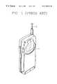
- a radiotelephone using a monopole antenna as described abovemust use an external antenna 3 which projects outward from the radiotelephone body 1 .
- a known alternative to the monopole type external antennais the general micro-strip patch antenna.
- the general micro-strip patch antennaalthough more compact, has several drawbacks, as will now be described.
- a general micro-strip patch antennamay use a dielectric ceramic, but requires two dielectric ceramic element parts for transmitting and receiving signals when the transmission and reception bandwidths are different from each other (as is usually the case with portable radiotelephones).
- FIG. 3shows a conventional internal antenna with a transmitting patch 30 , a transmitting dielectric ceramic 32 , a common ground 34 , a receiving dielectric ceramic 36 , and a receiving patch 38 .
- the two dielectric antennaswhich respectively perform the transmitting and receiving functions, are bonded to each other with the transmitting and receiving patches 30 and 38 facing outward.
- Such an antennareally is two dielectric antennas (one for transmission and one for reception), and it is difficult to reduce the size of a portable radiotelephone using such a general micro-strip antenna.
- a single micro-strip patch antenna for a portable radiotelephone transceiverwhich is internal, compact, capable of transmission and reception with only one dielectric ceramic part, and yet operable with separate transmission and reception frequency bandwidths by virtue of matching the antenna impedance to a main circuit impedance, and by supplying power to two frequency bandwidth terminals from one power supply source using strip lines on a printed circuit board.
- a micro-strip patch antenna for a radiotelephone transceiverincluding: a dielectric ceramic module for transmission and reception having a first ground plate, a dielectric ceramic mounted on the first ground plate for synchronizing frequencies, a conductive patch mounted on the dielectric ceramic for transmitting and receiving electromagnetic waves, a transmission power supply terminal formed to project from one side of the conductive patch to supply power for transmission, and a reception power supply terminal formed to project from another side of the conductive patch to supply power for reception; and a printed circuit board having a base, a second ground plate mounted on the base to contact the first ground plate, and strip lines formed on the base to be adjacent to the first ground plate and connected to the transmission and reception power supply terminals.
- FIG. 1is a schematic perspective view illustrating a radiotelephone having a conventional external antenna
- FIG. 2is a graph illustrating frequency characteristics of the antenna shown in FIG. 1;
- FIG. 3is a side view illustrating a conventional internal antenna
- FIG. 4is an exploded perspective view illustrating a micro-strip patch antenna for a radiotelephone transceiver according to an embodiment of the present invention.
- a micro-strip patch antenna for a portable and compact radiotelephone transceiverincludes a dielectric ceramic module 100 , and a printed circuit board (PCB) 200 .
- the PCB 200includes strip lines 220 .
- the dielectric ceramic module 100is comprised of a first ground plate 110 , a dielectric ceramic part 120 , a conductive patch 130 , a transmission power supply terminal 140 , and a reception power supply terminal 150 .
- the first ground plate 110as shown in FIG. 4, is adapted to be mounted on and to contact part of the PCB 200 , and functions as a ground.
- the dielectric ceramic part 120is disposed on the first ground plate 110 , and synchronizes frequencies.
- the conductive patch 130is disposed on the dielectric ceramic part 120 , and transmits and receives electromagnetic waves.
- the transmission power supply terminal 140projects from one side of the conductive patch 130 so as to supply power for transmission, and is connected to the strip lines 220 of the PCB 200 .
- the connection between the transmission power supply terminal 140 and the strip lines 220is omitted, for the sake of clarity, from FIG. 4 .
- the reception power supply terminal 150projects from one side of the conductive patch 130 so as to supply power for reception, and is likewise connected to the strip lines 220 of the PCB 200 in a not-shown connection.
- Conductive patch 130may be understood to have a lengthwise aspect indicated by reference numeral 160 , and a breadthwise aspect indicated by reference numeral 170 .
- the breadthwise and lengthwise sides of the conductive patch 130independently function as antennas. That is, the dielectric ceramic part 120 induces each side or aspect of the conductive patch 130 thereon to function as an independent antenna. That is, in the lengthwise aspect 160 of patch 130 a transmitting function is performed in which an electromagnetic wave is emitted to space by the charges supplied through the transmission power supply point 140 according to the natural frequency of the lengthwise side 160 of patch 130 .
- the breadthwise aspect 170 of patch 130performs a receiving function in which the breadthwise side 170 of patch 130 receives only the frequency synchronized with the natural frequency of the breadthwise aspect 170 of patch 130 . That is, when electromagnetic waves traveling through space enter into the dielectric ceramic part 120 , charges are generated in the breadthwise aspect 170 of patch 130 corresponding to the resonant frequency.
- the PCB 200comprises a base 201 , a second ground plate 210 disposed on the base 201 , strip lines 220 , a ground pattern 230 , and a cable connection point 240 .
- the second ground plate 210is adapted to be in electrical contact with the first ground plate 110 .
- the strip lines 220are arranged on the base 201 , and perform impedance matching between the antenna and a main board of the radiotelephone, and a one-channel dual power supply.
- the strip lines 220are arranged so as to equally supply power from the one power supply source to both the transmission side and the reception side. Therefore, the strip lines 220 make it possible to install the antenna without altering the circuit of the radiotelephone, and the impedance of the antenna can be matched to 50 ⁇ .
- ground pattern 230To facilitate soldering between the ground pattern 230 and a ground of the radiotelephone, a portion of the ground pattern 230 is provided. Part of the s ground pattern 230 overlaps with the first ground plate 110 , and the rest of ground pattern 230 leads out to the outside of the ground plates. The part that leads out is easy to solder to a ground of the radiotelephone.
- the cable connection point 240is a pad for the convenient connection of a 50 ⁇ cable.
- the conductive patch 130is designed to be synchronized to 959.0125-959.9875 MHz for a transmission antenna, and to 914.0125-914.9875 MHz for a reception antenna.
- the micro-strip patch antenna for a radiotelephone transceiverhas a structure in which transmission and reception is simultaneously carried out by only one dielectric ceramic part, and two sides or aspects of the patch serve as independent antennas.
- this inventive antennaprovides clear advantages in size and cost, in comparison with a conventional antenna using two ceramic elements for transmission and reception.
- an antenna according to the present inventioncan be directly installed in an existing radiotelephone without modification of the circuit to provide more than one channel for power.
- the antennain comparison with a conventional internal helical antenna, the antenna exhibits a high Q value, a longer communication distance, and excellent sensitivity due to selective resonance at a specific frequency.
Landscapes
- Engineering & Computer Science (AREA)
- Computer Networks & Wireless Communication (AREA)
- Waveguide Aerials (AREA)
- Support Of Aerials (AREA)
Abstract
Description
1. Field of the Invention
The present invention relates to a micro-strip patch antenna for a radiotelephone transceiver.
2. Description of the Related Art
Mobile radio terminals, such as portable radiotelephones, are getting smaller and lighter. In wireless communications, the antenna has a great influence on the performance of the radiotelephone. The antenna is the interface between the radiotelephone and free space. Since most “regular-sized” antennas exhibit close-to-theoretical performance when outside influence is not significant, they typically can easily be designed. Small antennas, however, have low radiation efficiency and a narrow frequency bandwidth. In addition, since a current may be induced in the radiotelephone body by electromagnetic interaction between antenna elements and the radiotelephone body, an electromagnetic wave may be radiated in an unexpected direction.
The types of linear antennas generally used in portable radiotelephones are the λ/2 monopole antenna (the length of which is set to half of the wavelength of the electromagnetic wave employed), a λ/4 monopole antenna (an improved version of the λ/2 monopole antenna), and a λ/2 whip antenna. These antennas have a length of 16 or 8 cm when the employed frequency is 900 MHz or 1.9 GHz, respectively, and can be enclosed in the radiotelephone body.
When the 900 MHz band is assigned as the frequency for radiotelephone communication, however, the length of the antenna must be 16 cm so as to receive the electromagnetic wave with the λ/2 monopole antenna.
Since the length of the above monopole antennas is relatively long, as depicted in FIG. 1, a radiotelephone using a monopole antenna as described above must use an external antenna3 which projects outward from theradiotelephone body 1.
In a radiotelephone having such an external antenna, as illustrated in an RF (radio frequency) characteristic curve shown in FIG. 2, it is difficult to attain the maximum gain at the upper and lower limit frequencies actually containing receiving (Rx) and transmitting (Tx) communication signals. Therefore, when the bandwidth is set to be wide (so as to attain the maximum gain), there arises a problem in that noise tends to interfere with the signal wave easily. Further, the monopole type external antenna is an element that severely limits the freedom of the designer in designing the radiotelephone.
A known alternative to the monopole type external antenna is the general micro-strip patch antenna. The general micro-strip patch antenna, although more compact, has several drawbacks, as will now be described.
A general micro-strip patch antenna may use a dielectric ceramic, but requires two dielectric ceramic element parts for transmitting and receiving signals when the transmission and reception bandwidths are different from each other (as is usually the case with portable radiotelephones).
FIG. 3 shows a conventional internal antenna with a transmittingpatch 30, a transmitting dielectric ceramic32, acommon ground 34, a receivingdielectric ceramic 36, and a receivingpatch 38. In a radiotelephone having separate transmitting and receiving frequency bandwidths, the two dielectric antennas, which respectively perform the transmitting and receiving functions, are bonded to each other with the transmitting and receivingpatches
Thus, such an antenna really is two dielectric antennas (one for transmission and one for reception), and it is difficult to reduce the size of a portable radiotelephone using such a general micro-strip antenna.
There are other problems with the general micro-strip antenna. For one thing, the supplying of power from what is typically a sole power supply point to the dielectric antennas is difficult, and it is also difficult to draw a common ground line. Further, the unit price of this type of antenna is high, and they are heavy enough to contribute significantly to the total weight of a radiotelephone. Furthermore, since the power to the antennas is normally supplied through only one channel, there is a disadvantage in that the main circuit of the radiotelephone must be altered because of the use of two antennas.
To solve the above and other problems, it is an objective of the present invention to provide a single micro-strip patch antenna for a portable radiotelephone transceiver which is internal, compact, capable of transmission and reception with only one dielectric ceramic part, and yet operable with separate transmission and reception frequency bandwidths by virtue of matching the antenna impedance to a main circuit impedance, and by supplying power to two frequency bandwidth terminals from one power supply source using strip lines on a printed circuit board.
Accordingly, to achieve the above objective, there is provided a micro-strip patch antenna for a radiotelephone transceiver including: a dielectric ceramic module for transmission and reception having a first ground plate, a dielectric ceramic mounted on the first ground plate for synchronizing frequencies, a conductive patch mounted on the dielectric ceramic for transmitting and receiving electromagnetic waves, a transmission power supply terminal formed to project from one side of the conductive patch to supply power for transmission, and a reception power supply terminal formed to project from another side of the conductive patch to supply power for reception; and a printed circuit board having a base, a second ground plate mounted on the base to contact the first ground plate, and strip lines formed on the base to be adjacent to the first ground plate and connected to the transmission and reception power supply terminals.
The above and other advantages of the present invention will become more is apparent by taking the below description of an embodiment of the invention together with reference to the attached drawings in which:
FIG. 1 is a schematic perspective view illustrating a radiotelephone having a conventional external antenna;
FIG. 2 is a graph illustrating frequency characteristics of the antenna shown in FIG. 1;
FIG. 3 is a side view illustrating a conventional internal antenna; and
FIG. 4 is an exploded perspective view illustrating a micro-strip patch antenna for a radiotelephone transceiver according to an embodiment of the present invention.
Referring to FIG. 4, a micro-strip patch antenna for a portable and compact radiotelephone transceiver according to an embodiment of the present invention includes a dielectricceramic module 100, and a printed circuit board (PCB)200. The PCB200 includesstrip lines 220.
The dielectricceramic module 100 is comprised of afirst ground plate 110, a dielectricceramic part 120, aconductive patch 130, a transmissionpower supply terminal 140, and a receptionpower supply terminal 150. Thefirst ground plate 110, as shown in FIG. 4, is adapted to be mounted on and to contact part of thePCB 200, and functions as a ground. The dielectricceramic part 120 is disposed on thefirst ground plate 110, and synchronizes frequencies. Theconductive patch 130 is disposed on the dielectricceramic part 120, and transmits and receives electromagnetic waves.
The transmissionpower supply terminal 140 projects from one side of theconductive patch 130 so as to supply power for transmission, and is connected to thestrip lines 220 of the PCB200. The connection between the transmissionpower supply terminal 140 and thestrip lines 220 is omitted, for the sake of clarity, from FIG.4.
The receptionpower supply terminal 150 projects from one side of theconductive patch 130 so as to supply power for reception, and is likewise connected to thestrip lines 220 of the PCB200 in a not-shown connection.
In the above antenna according to the present invention, the breadthwise and lengthwise sides of theconductive patch 130 independently function as antennas. That is, the dielectricceramic part 120 induces each side or aspect of theconductive patch 130 thereon to function as an independent antenna. That is, in thelengthwise aspect 160 of patch130 a transmitting function is performed in which an electromagnetic wave is emitted to space by the charges supplied through the transmissionpower supply point 140 according to the natural frequency of thelengthwise side 160 ofpatch 130. Thebreadthwise aspect 170 ofpatch 130 performs a receiving function in which thebreadthwise side 170 ofpatch 130 receives only the frequency synchronized with the natural frequency of thebreadthwise aspect 170 ofpatch 130. That is, when electromagnetic waves traveling through space enter into the dielectricceramic part 120, charges are generated in thebreadthwise aspect 170 ofpatch 130 corresponding to the resonant frequency.
The PCB200 comprises abase 201, asecond ground plate 210 disposed on thebase 201,strip lines 220, aground pattern 230, and acable connection point 240.
Thesecond ground plate 210 is adapted to be in electrical contact with thefirst ground plate 110. Thestrip lines 220 are arranged on thebase 201, and perform impedance matching between the antenna and a main board of the radiotelephone, and a one-channel dual power supply. In addition, since the power supply in a conventional radiotelephone is carried through one channel, thestrip lines 220 are arranged so as to equally supply power from the one power supply source to both the transmission side and the reception side. Therefore, thestrip lines 220 make it possible to install the antenna without altering the circuit of the radiotelephone, and the impedance of the antenna can be matched to 50 Ω.
To facilitate soldering between theground pattern 230 and a ground of the radiotelephone, a portion of theground pattern 230 is provided. Part of the sground pattern 230 overlaps with thefirst ground plate 110, and the rest ofground pattern 230 leads out to the outside of the ground plates. The part that leads out is easy to solder to a ground of the radiotelephone.
Thecable connection point 240 is a pad for the convenient connection of a 50 Ω cable.
When the antenna is used as an internal antenna of a 900 MHz radiotelephone, theconductive patch 130 is designed to be synchronized to 959.0125-959.9875 MHz for a transmission antenna, and to 914.0125-914.9875 MHz for a reception antenna.
The micro-strip patch antenna for a radiotelephone transceiver according to the present invention has a structure in which transmission and reception is simultaneously carried out by only one dielectric ceramic part, and two sides or aspects of the patch serve as independent antennas. In addition, this inventive antenna provides clear advantages in size and cost, in comparison with a conventional antenna using two ceramic elements for transmission and reception.
By virtue of the use ofstrip lines 220, which themselves perform impedance matching, there is no need to match the antenna impedance to 50 Ω in another manner, and a dual power supply can be used through one channel. Therefore, an antenna according to the present invention can be directly installed in an existing radiotelephone without modification of the circuit to provide more than one channel for power. In addition, in comparison with a conventional internal helical antenna, the antenna exhibits a high Q value, a longer communication distance, and excellent sensitivity due to selective resonance at a specific frequency.
Claims (10)
1. A micro-strip patch antenna for a radiotelephone transceiver, comprising:
a dielectric ceramic module for transmission and reception, comprising a first ground plate, a dielectric ceramic part disposed on the first ground plate, and a conductive patch disposed on the dielectric ceramic part and having power supply terminals; and
a circuit board, comprising a base, a second ground plate disposed on the base and connected to the first ground plate, and strip lines formed on the base, adjacent to but spaced from the first ground plate, and connected to the power supply terminals.
2. The micro-strip patch antenna for a radiotelephone transceiver as claimed in claim1, wherein the strip lines match the impedance of the antenna to that of a main circuit of the radiotelephone.
3. The micro-strip patch antenna for a radiotelephone transceiver as claimed in claim2, wherein the matching impedance of the strip lines is 50 Ω.
4. The micro-strip patch antenna for a radiotelephone transceiver as claimed in claim1, wherein the conductive patch is synchronized at 959.0125-959.9875 MHz for operation with one of the power supply terminals, and is synchronized at 914.0125-914.9875 MHz for operation with the other one of the power supply terminals.
5. A micro-strip patch antenna for a radiotelephone transceiver, comprising:
a dielectric ceramic module for transmission and reception, comprising a first ground plate, a dielectric ceramic part disposed on the first ground plate, and a conductive patch disposed on the dielectric ceramic part and having power supply terminals; and
a circuit board, comprising a base, a second ground plate disposed on the base and connected to the first ground plate, and strip lines formed on the base, adjacent to but spaced from the first ground plate, and connected to the power supply terminals;
wherein the circuit board further includes a ground pattern, a part thereof being overlapped with the first and second ground plates, another part thereof being exposed outside of the ground plates.
6. A micro-strip patch antenna for a radiotelephone transceiver including:
a dielectric ceramic module for transmission and reception, comprising only one dielectric ceramic part, a first ground plate, the dielectric ceramic part being disposed on the first ground plate, a conductive patch disposed on the dielectric ceramic part for transmitting and receiving electromagnetic waves, a transmission power supply power terminal formed to project from one side of the conductive patch to supply power for transmission, and a reception power supply terminal formed to project from another side of the conductive patch to supply power for reception; and
a circuit board, comprising a base, a second ground plate disposed on the base and connected to the first ground plate, and strip lines formed on the base, adjacent to but spaced from the first ground plate, and connected to the power supply terminals.
7. The micro-strip patch antenna for a radiotelephone transceiver as claimed in claim6, wherein the circuit board further includes a ground pattern, a part thereof being overlapped with the first and second ground plates, another part thereof being exposed outside of the ground planes.
8. The micro-strip patch antenna for a radiotelephone transceiver as claimed in claim6, wherein the strip lines match the impedance of the antenna to that of the main circuit of the radiotelephone.
9. The micro-strip patch antenna for a radiotelephone transceiver as claimed in claim8, wherein the matching impedance of the strip lines is 50 Ω.
10. The micro-strip patch antenna for a radiotelephone transceiver as claimed in claim6, wherein the conductive patch is synchronized at 959.0125-959.9875 MHZ for operation with one of the power supply terminals, and is synchronized at 914.0125-9149875 MHZ for operation with the other one of the power supply terminals.
Applications Claiming Priority (2)
| Application Number | Priority Date | Filing Date | Title |
|---|---|---|---|
| KR98-37529 | 1998-09-11 | ||
| KR10-1998-0037529AKR100467569B1 (en) | 1998-09-11 | 1998-09-11 | Microstrip patch antenna for transmitting and receiving |
Publications (1)
| Publication Number | Publication Date |
|---|---|
| US6195049B1true US6195049B1 (en) | 2001-02-27 |
Family
ID=19550311
Family Applications (1)
| Application Number | Title | Priority Date | Filing Date |
|---|---|---|---|
| US09/393,305Expired - LifetimeUS6195049B1 (en) | 1998-09-11 | 1999-09-10 | Micro-strip patch antenna for transceiver |
Country Status (2)
| Country | Link |
|---|---|
| US (1) | US6195049B1 (en) |
| KR (1) | KR100467569B1 (en) |
Cited By (79)
| Publication number | Priority date | Publication date | Assignee | Title |
|---|---|---|---|---|
| US6266020B1 (en)* | 2000-07-24 | 2001-07-24 | Auden Technology Mfg. Co. Ltd. | Hidden antenna device of a mobile phone |
| US6275192B1 (en)* | 2000-05-31 | 2001-08-14 | Samsung Electronics Co., Ltd. | Planar antenna |
| US6480171B1 (en)* | 2001-10-26 | 2002-11-12 | Hon Hai Precision Ind. Co., Ltd. | Impedance matching means between antenna and transmission cable |
| US20030027532A1 (en)* | 2001-07-17 | 2003-02-06 | Alps Electric Co., Ltd. | Miniaturized transmitter-receiver unit |
| US6583762B2 (en)* | 2001-01-11 | 2003-06-24 | The Furukawa Electric Co., Ltd. | Chip antenna and method of manufacturing the same |
| US20040224734A1 (en)* | 2003-04-28 | 2004-11-11 | Huei Lin | Portable wireless apparatus |
| US20050093747A1 (en)* | 2003-11-04 | 2005-05-05 | Mitsumi Electric Co. Ltd. | Patch antenna having a non-feeding element formed on a side surface of a dielectric |
| US20060092079A1 (en)* | 2004-10-01 | 2006-05-04 | De Rochemont L P | Ceramic antenna module and methods of manufacture thereof |
| WO2006051160A1 (en) | 2004-11-11 | 2006-05-18 | Pulse Finland Oy | Antenna component |
| WO2006084951A1 (en) | 2005-02-08 | 2006-08-17 | Pulse Finland Oy | Internal monopole antenna |
| US20070139976A1 (en)* | 2005-06-30 | 2007-06-21 | Derochemont L P | Power management module and method of manufacture |
| US20070152885A1 (en)* | 2004-06-28 | 2007-07-05 | Juha Sorvala | Chip antenna apparatus and methods |
| US20070171131A1 (en)* | 2004-06-28 | 2007-07-26 | Juha Sorvala | Antenna, component and methods |
| US20100177013A1 (en)* | 2007-03-20 | 2010-07-15 | Trixell | Mixed antenna |
| US20100220016A1 (en)* | 2005-10-03 | 2010-09-02 | Pertti Nissinen | Multiband Antenna System And Methods |
| US20100244978A1 (en)* | 2007-04-19 | 2010-09-30 | Zlatoljub Milosavljevic | Methods and apparatus for matching an antenna |
| US20100295737A1 (en)* | 2005-07-25 | 2010-11-25 | Zlatoljub Milosavljevic | Adjustable Multiband Antenna and Methods |
| US7903035B2 (en) | 2005-10-10 | 2011-03-08 | Pulse Finland Oy | Internal antenna and methods |
| US20110156972A1 (en)* | 2009-12-29 | 2011-06-30 | Heikki Korva | Loop resonator apparatus and methods for enhanced field control |
| CN102157798A (en)* | 2011-02-18 | 2011-08-17 | 厦门大学 | Beidou rectangular ceramic micro-strip antenna based on slot array |
| WO2012119818A1 (en)* | 2011-03-04 | 2012-09-13 | Rohde & Schwarz Gmbh & Co. Kg | Printed circuit board arrangement for millimeter wave scanners |
| US8354294B2 (en) | 2006-01-24 | 2013-01-15 | De Rochemont L Pierre | Liquid chemical deposition apparatus and process and products therefrom |
| US8473017B2 (en) | 2005-10-14 | 2013-06-25 | Pulse Finland Oy | Adjustable antenna and methods |
| US8552708B2 (en) | 2010-06-02 | 2013-10-08 | L. Pierre de Rochemont | Monolithic DC/DC power management module with surface FET |
| US8618990B2 (en) | 2011-04-13 | 2013-12-31 | Pulse Finland Oy | Wideband antenna and methods |
| US8629813B2 (en) | 2007-08-30 | 2014-01-14 | Pusle Finland Oy | Adjustable multi-band antenna and methods |
| US8648752B2 (en) | 2011-02-11 | 2014-02-11 | Pulse Finland Oy | Chassis-excited antenna apparatus and methods |
| US8715839B2 (en) | 2005-06-30 | 2014-05-06 | L. Pierre de Rochemont | Electrical components and method of manufacture |
| US8749054B2 (en) | 2010-06-24 | 2014-06-10 | L. Pierre de Rochemont | Semiconductor carrier with vertical power FET module |
| US8779489B2 (en) | 2010-08-23 | 2014-07-15 | L. Pierre de Rochemont | Power FET with a resonant transistor gate |
| US8866689B2 (en) | 2011-07-07 | 2014-10-21 | Pulse Finland Oy | Multi-band antenna and methods for long term evolution wireless system |
| US8922347B1 (en) | 2009-06-17 | 2014-12-30 | L. Pierre de Rochemont | R.F. energy collection circuit for wireless devices |
| US8952858B2 (en) | 2009-06-17 | 2015-02-10 | L. Pierre de Rochemont | Frequency-selective dipole antennas |
| US8988296B2 (en) | 2012-04-04 | 2015-03-24 | Pulse Finland Oy | Compact polarized antenna and methods |
| TWI483457B (en)* | 2008-12-24 | 2015-05-01 | E Ten Information System Co Ltd | Ceramic antenna holder and electronic device using the same |
| US9023493B2 (en) | 2010-07-13 | 2015-05-05 | L. Pierre de Rochemont | Chemically complex ablative max-phase material and method of manufacture |
| US9123990B2 (en) | 2011-10-07 | 2015-09-01 | Pulse Finland Oy | Multi-feed antenna apparatus and methods |
| US9123768B2 (en) | 2010-11-03 | 2015-09-01 | L. Pierre de Rochemont | Semiconductor chip carriers with monolithically integrated quantum dot devices and method of manufacture thereof |
| US9203154B2 (en) | 2011-01-25 | 2015-12-01 | Pulse Finland Oy | Multi-resonance antenna, antenna module, radio device and methods |
| US9246210B2 (en) | 2010-02-18 | 2016-01-26 | Pulse Finland Oy | Antenna with cover radiator and methods |
| US9350081B2 (en) | 2014-01-14 | 2016-05-24 | Pulse Finland Oy | Switchable multi-radiator high band antenna apparatus |
| US9406998B2 (en) | 2010-04-21 | 2016-08-02 | Pulse Finland Oy | Distributed multiband antenna and methods |
| US9450291B2 (en) | 2011-07-25 | 2016-09-20 | Pulse Finland Oy | Multiband slot loop antenna apparatus and methods |
| US9461371B2 (en) | 2009-11-27 | 2016-10-04 | Pulse Finland Oy | MIMO antenna and methods |
| US9484619B2 (en) | 2011-12-21 | 2016-11-01 | Pulse Finland Oy | Switchable diversity antenna apparatus and methods |
| US9531058B2 (en) | 2011-12-20 | 2016-12-27 | Pulse Finland Oy | Loosely-coupled radio antenna apparatus and methods |
| US9590308B2 (en) | 2013-12-03 | 2017-03-07 | Pulse Electronics, Inc. | Reduced surface area antenna apparatus and mobile communications devices incorporating the same |
| US9634383B2 (en) | 2013-06-26 | 2017-04-25 | Pulse Finland Oy | Galvanically separated non-interacting antenna sector apparatus and methods |
| US9647338B2 (en) | 2013-03-11 | 2017-05-09 | Pulse Finland Oy | Coupled antenna structure and methods |
| US9673507B2 (en) | 2011-02-11 | 2017-06-06 | Pulse Finland Oy | Chassis-excited antenna apparatus and methods |
| US9680212B2 (en) | 2013-11-20 | 2017-06-13 | Pulse Finland Oy | Capacitive grounding methods and apparatus for mobile devices |
| US9722308B2 (en) | 2014-08-28 | 2017-08-01 | Pulse Finland Oy | Low passive intermodulation distributed antenna system for multiple-input multiple-output systems and methods of use |
| US9761951B2 (en) | 2009-11-03 | 2017-09-12 | Pulse Finland Oy | Adjustable antenna apparatus and methods |
| US9906260B2 (en) | 2015-07-30 | 2018-02-27 | Pulse Finland Oy | Sensor-based closed loop antenna swapping apparatus and methods |
| US9948002B2 (en) | 2014-08-26 | 2018-04-17 | Pulse Finland Oy | Antenna apparatus with an integrated proximity sensor and methods |
| US9973228B2 (en) | 2014-08-26 | 2018-05-15 | Pulse Finland Oy | Antenna apparatus with an integrated proximity sensor and methods |
| US9979078B2 (en) | 2012-10-25 | 2018-05-22 | Pulse Finland Oy | Modular cell antenna apparatus and methods |
| US10069209B2 (en) | 2012-11-06 | 2018-09-04 | Pulse Finland Oy | Capacitively coupled antenna apparatus and methods |
| US10079428B2 (en) | 2013-03-11 | 2018-09-18 | Pulse Finland Oy | Coupled antenna structure and methods |
| US10211538B2 (en) | 2006-12-28 | 2019-02-19 | Pulse Finland Oy | Directional antenna apparatus and methods |
| WO2021190333A1 (en) | 2020-03-24 | 2021-09-30 | 安川昌昭 | Electromagnetic wave transceiving apparatus |
| USD940149S1 (en) | 2017-06-08 | 2022-01-04 | Insulet Corporation | Display screen with a graphical user interface |
| CN114944552A (en)* | 2021-02-16 | 2022-08-26 | 东友精细化工有限公司 | Antenna structure and image display device |
| USD977502S1 (en) | 2020-06-09 | 2023-02-07 | Insulet Corporation | Display screen with graphical user interface |
| US11857763B2 (en) | 2016-01-14 | 2024-01-02 | Insulet Corporation | Adjusting insulin delivery rates |
| US11865299B2 (en) | 2008-08-20 | 2024-01-09 | Insulet Corporation | Infusion pump systems and methods |
| US11929158B2 (en) | 2016-01-13 | 2024-03-12 | Insulet Corporation | User interface for diabetes management system |
| USD1020794S1 (en) | 2018-04-02 | 2024-04-02 | Bigfoot Biomedical, Inc. | Medication delivery device with icons |
| USD1024090S1 (en) | 2019-01-09 | 2024-04-23 | Bigfoot Biomedical, Inc. | Display screen or portion thereof with graphical user interface associated with insulin delivery |
| US11969579B2 (en) | 2017-01-13 | 2024-04-30 | Insulet Corporation | Insulin delivery methods, systems and devices |
| US12042630B2 (en) | 2017-01-13 | 2024-07-23 | Insulet Corporation | System and method for adjusting insulin delivery |
| US12064591B2 (en) | 2013-07-19 | 2024-08-20 | Insulet Corporation | Infusion pump system and method |
| US12076160B2 (en) | 2016-12-12 | 2024-09-03 | Insulet Corporation | Alarms and alerts for medication delivery devices and systems |
| US12097355B2 (en) | 2023-01-06 | 2024-09-24 | Insulet Corporation | Automatically or manually initiated meal bolus delivery with subsequent automatic safety constraint relaxation |
| US12106837B2 (en) | 2016-01-14 | 2024-10-01 | Insulet Corporation | Occlusion resolution in medication delivery devices, systems, and methods |
| US12318577B2 (en) | 2017-01-13 | 2025-06-03 | Insulet Corporation | System and method for adjusting insulin delivery |
| US12318594B2 (en) | 2016-05-26 | 2025-06-03 | Insulet Corporation | On-body interlock for drug delivery device |
| US12343502B2 (en) | 2017-01-13 | 2025-07-01 | Insulet Corporation | System and method for adjusting insulin delivery |
| US12383166B2 (en) | 2016-05-23 | 2025-08-12 | Insulet Corporation | Insulin delivery system and methods with risk-based set points |
Families Citing this family (6)
| Publication number | Priority date | Publication date | Assignee | Title |
|---|---|---|---|---|
| JP2003258539A (en)* | 2002-03-06 | 2003-09-12 | Communication Research Laboratory | Microstrip antenna |
| KR100533624B1 (en)* | 2002-04-16 | 2005-12-06 | 삼성전기주식회사 | Multi band chip antenna with dual feeding port, and mobile communication apparatus using the same |
| KR100921494B1 (en)* | 2008-03-28 | 2009-10-13 | 삼성탈레스 주식회사 | Multiple Resonant Broadband Small Antenna |
| KR102096417B1 (en) | 2017-02-28 | 2020-04-02 | 동우 화인켐 주식회사 | Film type microstrip patch antenna |
| KR102356678B1 (en) | 2020-03-16 | 2022-01-26 | 동우 화인켐 주식회사 | Antenna device and display device including the same |
| KR102367163B1 (en)* | 2021-07-05 | 2022-02-23 | 동우 화인켐 주식회사 | Antenna structure and image display device including the same |
Citations (5)
| Publication number | Priority date | Publication date | Assignee | Title |
|---|---|---|---|---|
| US5861854A (en)* | 1996-06-19 | 1999-01-19 | Murata Mfg. Co. Ltd. | Surface-mount antenna and a communication apparatus using the same |
| US5909198A (en)* | 1996-12-25 | 1999-06-01 | Murata Manufacturing Co., Ltd. | Chip antenna |
| US5969680A (en)* | 1994-10-11 | 1999-10-19 | Murata Manufacturing Co., Ltd. | Antenna device having a radiating portion provided between a wiring substrate and a case |
| US5977915A (en)* | 1997-06-27 | 1999-11-02 | Telefonaktiebolaget Lm Ericsson | Microstrip structure |
| US6061025A (en)* | 1995-12-07 | 2000-05-09 | Atlantic Aerospace Electronics Corporation | Tunable microstrip patch antenna and control system therefor |
Family Cites Families (1)
| Publication number | Priority date | Publication date | Assignee | Title |
|---|---|---|---|---|
| US5231406A (en)* | 1991-04-05 | 1993-07-27 | Ball Corporation | Broadband circular polarization satellite antenna |
- 1998
- 1998-09-11KRKR10-1998-0037529Apatent/KR100467569B1/ennot_activeExpired - Fee Related
- 1999
- 1999-09-10USUS09/393,305patent/US6195049B1/ennot_activeExpired - Lifetime
Patent Citations (5)
| Publication number | Priority date | Publication date | Assignee | Title |
|---|---|---|---|---|
| US5969680A (en)* | 1994-10-11 | 1999-10-19 | Murata Manufacturing Co., Ltd. | Antenna device having a radiating portion provided between a wiring substrate and a case |
| US6061025A (en)* | 1995-12-07 | 2000-05-09 | Atlantic Aerospace Electronics Corporation | Tunable microstrip patch antenna and control system therefor |
| US5861854A (en)* | 1996-06-19 | 1999-01-19 | Murata Mfg. Co. Ltd. | Surface-mount antenna and a communication apparatus using the same |
| US5909198A (en)* | 1996-12-25 | 1999-06-01 | Murata Manufacturing Co., Ltd. | Chip antenna |
| US5977915A (en)* | 1997-06-27 | 1999-11-02 | Telefonaktiebolaget Lm Ericsson | Microstrip structure |
Cited By (122)
| Publication number | Priority date | Publication date | Assignee | Title |
|---|---|---|---|---|
| US6275192B1 (en)* | 2000-05-31 | 2001-08-14 | Samsung Electronics Co., Ltd. | Planar antenna |
| US6266020B1 (en)* | 2000-07-24 | 2001-07-24 | Auden Technology Mfg. Co. Ltd. | Hidden antenna device of a mobile phone |
| US6583762B2 (en)* | 2001-01-11 | 2003-06-24 | The Furukawa Electric Co., Ltd. | Chip antenna and method of manufacturing the same |
| US7046969B2 (en) | 2001-07-17 | 2006-05-16 | Alps Electric Co., Ltd. | Miniaturized transmitter-receiver unit |
| US20030027532A1 (en)* | 2001-07-17 | 2003-02-06 | Alps Electric Co., Ltd. | Miniaturized transmitter-receiver unit |
| US6480171B1 (en)* | 2001-10-26 | 2002-11-12 | Hon Hai Precision Ind. Co., Ltd. | Impedance matching means between antenna and transmission cable |
| US9735148B2 (en) | 2002-02-19 | 2017-08-15 | L. Pierre de Rochemont | Semiconductor carrier with vertical power FET module |
| US20040224734A1 (en)* | 2003-04-28 | 2004-11-11 | Huei Lin | Portable wireless apparatus |
| US7146201B2 (en)* | 2003-04-28 | 2006-12-05 | Quanta Computer Inc. | Portable wireless apparatus |
| US7042399B2 (en)* | 2003-11-04 | 2006-05-09 | Mitsumi Electric Co., Ltd. | Patch antenna having a non-feeding element formed on a side surface of a dielectric |
| US20050093747A1 (en)* | 2003-11-04 | 2005-05-05 | Mitsumi Electric Co. Ltd. | Patch antenna having a non-feeding element formed on a side surface of a dielectric |
| US8390522B2 (en) | 2004-06-28 | 2013-03-05 | Pulse Finland Oy | Antenna, component and methods |
| US7679565B2 (en) | 2004-06-28 | 2010-03-16 | Pulse Finland Oy | Chip antenna apparatus and methods |
| US8004470B2 (en) | 2004-06-28 | 2011-08-23 | Pulse Finland Oy | Antenna, component and methods |
| US20070152885A1 (en)* | 2004-06-28 | 2007-07-05 | Juha Sorvala | Chip antenna apparatus and methods |
| US20070171131A1 (en)* | 2004-06-28 | 2007-07-26 | Juha Sorvala | Antenna, component and methods |
| US7973720B2 (en) | 2004-06-28 | 2011-07-05 | LKP Pulse Finland OY | Chip antenna apparatus and methods |
| US20100321250A1 (en)* | 2004-06-28 | 2010-12-23 | Juha Sorvala | Antenna, Component and Methods |
| US7786938B2 (en) | 2004-06-28 | 2010-08-31 | Pulse Finland Oy | Antenna, component and methods |
| US20100176998A1 (en)* | 2004-06-28 | 2010-07-15 | Juha Sorvala | Chip antenna apparatus and methods |
| US9520649B2 (en) | 2004-10-01 | 2016-12-13 | L. Pierre de Rochemont | Ceramic antenna module and methods of manufacture thereof |
| US8178457B2 (en) | 2004-10-01 | 2012-05-15 | De Rochemont L Pierre | Ceramic antenna module and methods of manufacture thereof |
| US8593819B2 (en) | 2004-10-01 | 2013-11-26 | L. Pierre de Rochemont | Ceramic antenna module and methods of manufacture thereof |
| US10673130B2 (en) | 2004-10-01 | 2020-06-02 | L. Pierre de Rochemont | Ceramic antenna module and methods of manufacture thereof |
| US9882274B2 (en) | 2004-10-01 | 2018-01-30 | L. Pierre de Rochemont | Ceramic antenna module and methods of manufacture thereof |
| US20060092079A1 (en)* | 2004-10-01 | 2006-05-04 | De Rochemont L P | Ceramic antenna module and methods of manufacture thereof |
| US7405698B2 (en) | 2004-10-01 | 2008-07-29 | De Rochemont L Pierre | Ceramic antenna module and methods of manufacture thereof |
| US20090011922A1 (en)* | 2004-10-01 | 2009-01-08 | De Rochemont L Pierre | Ceramic antenna module and methods of manufacture thereof |
| EP1810366A4 (en)* | 2004-11-11 | 2008-12-17 | Lk Products Oy | ANTENNA COMPONENT |
| WO2006051160A1 (en) | 2004-11-11 | 2006-05-18 | Pulse Finland Oy | Antenna component |
| US7916086B2 (en) | 2004-11-11 | 2011-03-29 | Pulse Finland Oy | Antenna component and methods |
| US20080007459A1 (en)* | 2004-11-11 | 2008-01-10 | Kimmo Koskiniemi | Antenna component and methods |
| WO2006084951A1 (en) | 2005-02-08 | 2006-08-17 | Pulse Finland Oy | Internal monopole antenna |
| US8350657B2 (en) | 2005-06-30 | 2013-01-08 | Derochemont L Pierre | Power management module and method of manufacture |
| US20070139976A1 (en)* | 2005-06-30 | 2007-06-21 | Derochemont L P | Power management module and method of manufacture |
| US10475568B2 (en) | 2005-06-30 | 2019-11-12 | L. Pierre De Rochemont | Power management module and method of manufacture |
| US9905928B2 (en) | 2005-06-30 | 2018-02-27 | L. Pierre de Rochemont | Electrical components and method of manufacture |
| US8715839B2 (en) | 2005-06-30 | 2014-05-06 | L. Pierre de Rochemont | Electrical components and method of manufacture |
| US20100295737A1 (en)* | 2005-07-25 | 2010-11-25 | Zlatoljub Milosavljevic | Adjustable Multiband Antenna and Methods |
| US8564485B2 (en) | 2005-07-25 | 2013-10-22 | Pulse Finland Oy | Adjustable multiband antenna and methods |
| US20100220016A1 (en)* | 2005-10-03 | 2010-09-02 | Pertti Nissinen | Multiband Antenna System And Methods |
| US8786499B2 (en) | 2005-10-03 | 2014-07-22 | Pulse Finland Oy | Multiband antenna system and methods |
| US7903035B2 (en) | 2005-10-10 | 2011-03-08 | Pulse Finland Oy | Internal antenna and methods |
| US8473017B2 (en) | 2005-10-14 | 2013-06-25 | Pulse Finland Oy | Adjustable antenna and methods |
| US8354294B2 (en) | 2006-01-24 | 2013-01-15 | De Rochemont L Pierre | Liquid chemical deposition apparatus and process and products therefrom |
| US8715814B2 (en) | 2006-01-24 | 2014-05-06 | L. Pierre de Rochemont | Liquid chemical deposition apparatus and process and products therefrom |
| US10211538B2 (en) | 2006-12-28 | 2019-02-19 | Pulse Finland Oy | Directional antenna apparatus and methods |
| US20100177013A1 (en)* | 2007-03-20 | 2010-07-15 | Trixell | Mixed antenna |
| US8466756B2 (en) | 2007-04-19 | 2013-06-18 | Pulse Finland Oy | Methods and apparatus for matching an antenna |
| US20100244978A1 (en)* | 2007-04-19 | 2010-09-30 | Zlatoljub Milosavljevic | Methods and apparatus for matching an antenna |
| US8629813B2 (en) | 2007-08-30 | 2014-01-14 | Pusle Finland Oy | Adjustable multi-band antenna and methods |
| US12296139B2 (en) | 2008-08-20 | 2025-05-13 | Insulet Corporation | Infusion pump systems and methods |
| US11865299B2 (en) | 2008-08-20 | 2024-01-09 | Insulet Corporation | Infusion pump systems and methods |
| TWI483457B (en)* | 2008-12-24 | 2015-05-01 | E Ten Information System Co Ltd | Ceramic antenna holder and electronic device using the same |
| US9847581B2 (en) | 2009-06-17 | 2017-12-19 | L. Pierre de Rochemont | Frequency-selective dipole antennas |
| US8952858B2 (en) | 2009-06-17 | 2015-02-10 | L. Pierre de Rochemont | Frequency-selective dipole antennas |
| US8922347B1 (en) | 2009-06-17 | 2014-12-30 | L. Pierre de Rochemont | R.F. energy collection circuit for wireless devices |
| US9893564B2 (en) | 2009-06-17 | 2018-02-13 | L. Pierre de Rochemont | R.F. energy collection circuit for wireless devices |
| US11063365B2 (en) | 2009-06-17 | 2021-07-13 | L. Pierre de Rochemont | Frequency-selective dipole antennas |
| US9761951B2 (en) | 2009-11-03 | 2017-09-12 | Pulse Finland Oy | Adjustable antenna apparatus and methods |
| US9461371B2 (en) | 2009-11-27 | 2016-10-04 | Pulse Finland Oy | MIMO antenna and methods |
| US20110156972A1 (en)* | 2009-12-29 | 2011-06-30 | Heikki Korva | Loop resonator apparatus and methods for enhanced field control |
| US8847833B2 (en) | 2009-12-29 | 2014-09-30 | Pulse Finland Oy | Loop resonator apparatus and methods for enhanced field control |
| US9246210B2 (en) | 2010-02-18 | 2016-01-26 | Pulse Finland Oy | Antenna with cover radiator and methods |
| US9406998B2 (en) | 2010-04-21 | 2016-08-02 | Pulse Finland Oy | Distributed multiband antenna and methods |
| US8552708B2 (en) | 2010-06-02 | 2013-10-08 | L. Pierre de Rochemont | Monolithic DC/DC power management module with surface FET |
| US10483260B2 (en) | 2010-06-24 | 2019-11-19 | L. Pierre de Rochemont | Semiconductor carrier with vertical power FET module |
| US8749054B2 (en) | 2010-06-24 | 2014-06-10 | L. Pierre de Rochemont | Semiconductor carrier with vertical power FET module |
| US9023493B2 (en) | 2010-07-13 | 2015-05-05 | L. Pierre de Rochemont | Chemically complex ablative max-phase material and method of manufacture |
| US10683705B2 (en) | 2010-07-13 | 2020-06-16 | L. Pierre de Rochemont | Cutting tool and method of manufacture |
| US8779489B2 (en) | 2010-08-23 | 2014-07-15 | L. Pierre de Rochemont | Power FET with a resonant transistor gate |
| US9123768B2 (en) | 2010-11-03 | 2015-09-01 | L. Pierre de Rochemont | Semiconductor chip carriers with monolithically integrated quantum dot devices and method of manufacture thereof |
| US10777409B2 (en) | 2010-11-03 | 2020-09-15 | L. Pierre de Rochemont | Semiconductor chip carriers with monolithically integrated quantum dot devices and method of manufacture thereof |
| US9203154B2 (en) | 2011-01-25 | 2015-12-01 | Pulse Finland Oy | Multi-resonance antenna, antenna module, radio device and methods |
| US9673507B2 (en) | 2011-02-11 | 2017-06-06 | Pulse Finland Oy | Chassis-excited antenna apparatus and methods |
| US8648752B2 (en) | 2011-02-11 | 2014-02-11 | Pulse Finland Oy | Chassis-excited antenna apparatus and methods |
| US9917346B2 (en) | 2011-02-11 | 2018-03-13 | Pulse Finland Oy | Chassis-excited antenna apparatus and methods |
| CN102157798A (en)* | 2011-02-18 | 2011-08-17 | 厦门大学 | Beidou rectangular ceramic micro-strip antenna based on slot array |
| WO2012119818A1 (en)* | 2011-03-04 | 2012-09-13 | Rohde & Schwarz Gmbh & Co. Kg | Printed circuit board arrangement for millimeter wave scanners |
| US9265151B2 (en) | 2011-03-04 | 2016-02-16 | Rohde & Schwarz Gmbh & Co. Kg | Printed-circuit board arrangement for millimeter-wave scanners |
| US8618990B2 (en) | 2011-04-13 | 2013-12-31 | Pulse Finland Oy | Wideband antenna and methods |
| US8866689B2 (en) | 2011-07-07 | 2014-10-21 | Pulse Finland Oy | Multi-band antenna and methods for long term evolution wireless system |
| US9450291B2 (en) | 2011-07-25 | 2016-09-20 | Pulse Finland Oy | Multiband slot loop antenna apparatus and methods |
| US9123990B2 (en) | 2011-10-07 | 2015-09-01 | Pulse Finland Oy | Multi-feed antenna apparatus and methods |
| US9531058B2 (en) | 2011-12-20 | 2016-12-27 | Pulse Finland Oy | Loosely-coupled radio antenna apparatus and methods |
| US9484619B2 (en) | 2011-12-21 | 2016-11-01 | Pulse Finland Oy | Switchable diversity antenna apparatus and methods |
| US9509054B2 (en) | 2012-04-04 | 2016-11-29 | Pulse Finland Oy | Compact polarized antenna and methods |
| US8988296B2 (en) | 2012-04-04 | 2015-03-24 | Pulse Finland Oy | Compact polarized antenna and methods |
| US9979078B2 (en) | 2012-10-25 | 2018-05-22 | Pulse Finland Oy | Modular cell antenna apparatus and methods |
| US10069209B2 (en) | 2012-11-06 | 2018-09-04 | Pulse Finland Oy | Capacitively coupled antenna apparatus and methods |
| US10079428B2 (en) | 2013-03-11 | 2018-09-18 | Pulse Finland Oy | Coupled antenna structure and methods |
| US9647338B2 (en) | 2013-03-11 | 2017-05-09 | Pulse Finland Oy | Coupled antenna structure and methods |
| US9634383B2 (en) | 2013-06-26 | 2017-04-25 | Pulse Finland Oy | Galvanically separated non-interacting antenna sector apparatus and methods |
| US12064591B2 (en) | 2013-07-19 | 2024-08-20 | Insulet Corporation | Infusion pump system and method |
| US9680212B2 (en) | 2013-11-20 | 2017-06-13 | Pulse Finland Oy | Capacitive grounding methods and apparatus for mobile devices |
| US9590308B2 (en) | 2013-12-03 | 2017-03-07 | Pulse Electronics, Inc. | Reduced surface area antenna apparatus and mobile communications devices incorporating the same |
| US9350081B2 (en) | 2014-01-14 | 2016-05-24 | Pulse Finland Oy | Switchable multi-radiator high band antenna apparatus |
| US9948002B2 (en) | 2014-08-26 | 2018-04-17 | Pulse Finland Oy | Antenna apparatus with an integrated proximity sensor and methods |
| US9973228B2 (en) | 2014-08-26 | 2018-05-15 | Pulse Finland Oy | Antenna apparatus with an integrated proximity sensor and methods |
| US9722308B2 (en) | 2014-08-28 | 2017-08-01 | Pulse Finland Oy | Low passive intermodulation distributed antenna system for multiple-input multiple-output systems and methods of use |
| US9906260B2 (en) | 2015-07-30 | 2018-02-27 | Pulse Finland Oy | Sensor-based closed loop antenna swapping apparatus and methods |
| US11929158B2 (en) | 2016-01-13 | 2024-03-12 | Insulet Corporation | User interface for diabetes management system |
| US12106837B2 (en) | 2016-01-14 | 2024-10-01 | Insulet Corporation | Occlusion resolution in medication delivery devices, systems, and methods |
| US11857763B2 (en) | 2016-01-14 | 2024-01-02 | Insulet Corporation | Adjusting insulin delivery rates |
| US12303668B2 (en) | 2016-01-14 | 2025-05-20 | Insulet Corporation | Adjusting insulin delivery rates |
| US12303667B2 (en) | 2016-01-14 | 2025-05-20 | Insulet Corporation | Adjusting insulin delivery rates |
| US12383166B2 (en) | 2016-05-23 | 2025-08-12 | Insulet Corporation | Insulin delivery system and methods with risk-based set points |
| US12318594B2 (en) | 2016-05-26 | 2025-06-03 | Insulet Corporation | On-body interlock for drug delivery device |
| US12076160B2 (en) | 2016-12-12 | 2024-09-03 | Insulet Corporation | Alarms and alerts for medication delivery devices and systems |
| US12318577B2 (en) | 2017-01-13 | 2025-06-03 | Insulet Corporation | System and method for adjusting insulin delivery |
| US12042630B2 (en) | 2017-01-13 | 2024-07-23 | Insulet Corporation | System and method for adjusting insulin delivery |
| US11969579B2 (en) | 2017-01-13 | 2024-04-30 | Insulet Corporation | Insulin delivery methods, systems and devices |
| US12161841B2 (en) | 2017-01-13 | 2024-12-10 | Insulet Corporation | Insulin delivery methods, systems and devices |
| US12343502B2 (en) | 2017-01-13 | 2025-07-01 | Insulet Corporation | System and method for adjusting insulin delivery |
| USD940149S1 (en) | 2017-06-08 | 2022-01-04 | Insulet Corporation | Display screen with a graphical user interface |
| USD1020794S1 (en) | 2018-04-02 | 2024-04-02 | Bigfoot Biomedical, Inc. | Medication delivery device with icons |
| USD1024090S1 (en) | 2019-01-09 | 2024-04-23 | Bigfoot Biomedical, Inc. | Display screen or portion thereof with graphical user interface associated with insulin delivery |
| WO2021190333A1 (en) | 2020-03-24 | 2021-09-30 | 安川昌昭 | Electromagnetic wave transceiving apparatus |
| US11387562B2 (en)* | 2020-03-24 | 2022-07-12 | Eiko Techno Corp | Electromagnetic wave transceiving apparutus |
| USD977502S1 (en) | 2020-06-09 | 2023-02-07 | Insulet Corporation | Display screen with graphical user interface |
| CN114944552A (en)* | 2021-02-16 | 2022-08-26 | 东友精细化工有限公司 | Antenna structure and image display device |
| US12097355B2 (en) | 2023-01-06 | 2024-09-24 | Insulet Corporation | Automatically or manually initiated meal bolus delivery with subsequent automatic safety constraint relaxation |
Also Published As
| Publication number | Publication date |
|---|---|
| KR100467569B1 (en) | 2005-03-16 |
| KR20000019433A (en) | 2000-04-15 |
Similar Documents
| Publication | Publication Date | Title |
|---|---|---|
| US6195049B1 (en) | Micro-strip patch antenna for transceiver | |
| KR100714923B1 (en) | Wireless communication device including antenna device and antenna device | |
| US7443344B2 (en) | Antenna arrangement and a module and a radio communications apparatus having such an arrangement | |
| US4571595A (en) | Dual band transceiver antenna | |
| US6046703A (en) | Compact wireless transceiver board with directional printed circuit antenna | |
| JP4132669B2 (en) | Dual-band diversity antenna with parasitic radiating elements | |
| US5914690A (en) | Antenna for wireless communications devices | |
| EP1506594B1 (en) | Antenna arrangement and module including the arrangement | |
| US7058434B2 (en) | Mobile communication | |
| US6218992B1 (en) | Compact, broadband inverted-F antennas with conductive elements and wireless communicators incorporating same | |
| US6016126A (en) | Non-protruding dual-band antenna for communications device | |
| US6225951B1 (en) | Antenna systems having capacitively coupled internal and retractable antennas and wireless communicators incorporating same | |
| US6326919B1 (en) | Patch antenna | |
| US20050116865A1 (en) | Multifrequency inverted-F antenna | |
| US10230160B2 (en) | Wireless communication system and wearable electronic device including the same | |
| JP2007510362A (en) | Multiband flat plate inverted F antenna including floating non-excitation element and wireless terminal incorporating the same | |
| KR20040099274A (en) | Oriented PIFA-Type Device and Method of Use for Reducing RF Interface | |
| KR20000076272A (en) | Antenna assembly for telecommunication devices | |
| WO2001013464A1 (en) | A dual band bowtie/meander antenna | |
| JPWO2004109857A1 (en) | Antenna and electronic equipment using it | |
| WO2002037600A1 (en) | End-fed antenna with counterpoise for a mobile terminal | |
| US6697023B1 (en) | Built-in multi-band mobile phone antenna with meandering conductive portions | |
| US20020123312A1 (en) | Antenna systems including internal planar inverted-F Antenna coupled with external radiating element and wireless communicators incorporating same | |
| US20080272964A1 (en) | Antenna Radiator Assembly and Radio Communications Assembly | |
| JP2002026627A (en) | Antenna system and mobile wireless terminal |
Legal Events
| Date | Code | Title | Description |
|---|---|---|---|
| AS | Assignment | Owner name:SAMSUNG ELECTRONICS, CO., LTD., KOREA, REPUBLIC OF Free format text:ASSIGNMENT OF ASSIGNORS INTEREST;ASSIGNORS:KIM, YOUNG-EIL;KIM, DUCK-SU;LEE, SUNG-SOO;REEL/FRAME:010237/0098 Effective date:19990906 | |
| FEPP | Fee payment procedure | Free format text:PAYOR NUMBER ASSIGNED (ORIGINAL EVENT CODE: ASPN); ENTITY STATUS OF PATENT OWNER: LARGE ENTITY | |
| STCF | Information on status: patent grant | Free format text:PATENTED CASE | |
| FPAY | Fee payment | Year of fee payment:4 | |
| FPAY | Fee payment | Year of fee payment:8 | |
| FEPP | Fee payment procedure | Free format text:PAYER NUMBER DE-ASSIGNED (ORIGINAL EVENT CODE: RMPN); ENTITY STATUS OF PATENT OWNER: LARGE ENTITY Free format text:PAYOR NUMBER ASSIGNED (ORIGINAL EVENT CODE: ASPN); ENTITY STATUS OF PATENT OWNER: LARGE ENTITY | |
| FPAY | Fee payment | Year of fee payment:12 |