US6193718B1 - Endoscopic electrocautery instrument - Google Patents
Endoscopic electrocautery instrumentDownload PDFInfo
- Publication number
- US6193718B1 US6193718B1US09/095,307US9530798AUS6193718B1US 6193718 B1US6193718 B1US 6193718B1US 9530798 AUS9530798 AUS 9530798AUS 6193718 B1US6193718 B1US 6193718B1
- Authority
- US
- United States
- Prior art keywords
- conductive layer
- proximal
- electrocautery instrument
- end effector
- endoscopic
- Prior art date
- Legal status (The legal status is an assumption and is not a legal conclusion. Google has not performed a legal analysis and makes no representation as to the accuracy of the status listed.)
- Expired - Fee Related
Links
Images


Classifications
- A—HUMAN NECESSITIES
- A61—MEDICAL OR VETERINARY SCIENCE; HYGIENE
- A61B—DIAGNOSIS; SURGERY; IDENTIFICATION
- A61B18/00—Surgical instruments, devices or methods for transferring non-mechanical forms of energy to or from the body
- A61B18/04—Surgical instruments, devices or methods for transferring non-mechanical forms of energy to or from the body by heating
- A61B18/12—Surgical instruments, devices or methods for transferring non-mechanical forms of energy to or from the body by heating by passing a current through the tissue to be heated, e.g. high-frequency current
- A61B18/14—Probes or electrodes therefor
- A61B18/1442—Probes having pivoting end effectors, e.g. forceps
- A61B18/1445—Probes having pivoting end effectors, e.g. forceps at the distal end of a shaft, e.g. forceps or scissors at the end of a rigid rod
- A—HUMAN NECESSITIES
- A61—MEDICAL OR VETERINARY SCIENCE; HYGIENE
- A61B—DIAGNOSIS; SURGERY; IDENTIFICATION
- A61B18/00—Surgical instruments, devices or methods for transferring non-mechanical forms of energy to or from the body
- A61B18/04—Surgical instruments, devices or methods for transferring non-mechanical forms of energy to or from the body by heating
- A61B18/12—Surgical instruments, devices or methods for transferring non-mechanical forms of energy to or from the body by heating by passing a current through the tissue to be heated, e.g. high-frequency current
- A61B18/1206—Generators therefor
- A61B2018/1246—Generators therefor characterised by the output polarity
- A61B2018/126—Generators therefor characterised by the output polarity bipolar
- A—HUMAN NECESSITIES
- A61—MEDICAL OR VETERINARY SCIENCE; HYGIENE
- A61B—DIAGNOSIS; SURGERY; IDENTIFICATION
- A61B18/00—Surgical instruments, devices or methods for transferring non-mechanical forms of energy to or from the body
- A61B18/04—Surgical instruments, devices or methods for transferring non-mechanical forms of energy to or from the body by heating
- A61B18/12—Surgical instruments, devices or methods for transferring non-mechanical forms of energy to or from the body by heating by passing a current through the tissue to be heated, e.g. high-frequency current
- A61B18/14—Probes or electrodes therefor
- A61B2018/1405—Electrodes having a specific shape
- A61B2018/1412—Blade
Definitions
- This inventionrelates to surgical apparatus, and more particularly to endoscopic electrocautery instruments such as bipolar scissors.
- Endoscopic surgeryis widely practiced throughout the world today and its acceptance is rapidly growing. Much of the popularity of endoscopic surgery can be attributed to its a less invasive, less traumatic affect upon the patient in comparison with standard open type surgery.
- One type of endoscopic surgeryinvolves placing trocar tubes into the patient through incisions and inserting endoscopic surgical tools through the trocar tubes for performing operations at a surgery site.
- a camera, magnifying lens, or other optical instrumentis often inserted through one trocar tube, while a cutter, dissector, or other surgical instrument is inserted through the same or another trocar tube.
- the cutter, dissector, or other instrumentis used to manipulate and/or cut tissue or organs of the patient. It may be desirable to utilize several trocar tubes at once to receive numerous surgical instruments. In this manner, a patient's organs or tissue may be, for example, grasped with one surgical instrument and simultaneously cut with another, all under the view of the surgeon via an optical instrument inserted through a trocar tube.
- Certain of these instrumentsmay generally include an elongated, slender tube containing a push rod which is axially movable within the tube by way a handle or trigger-like actuator.
- An end effectoris normally provided at the distal end of the tube and is coupled to the push rod so that axial movement of the push rod translates to rotational or pivotal movement of the end effector.
- End effectorsmay be, for example, scissor blades, grippers, cutting jaws, or forceps.
- Electrocauterypasses cautery current to the surgery site to cauterize open blood vessels. Beyond reducing blood loss, electrocautery aids the operation by providing a clearer view of the surgical site.
- cauteryelectrocautery
- coagulationis interchangeable.
- Bipolar electrocautery instrumentsgenerally include two electrodes closely spaced for contact with organs and tissue of the patient.
- a bipolar electrocautery instrumenttypically includes two end effectors, one end effector acting as a first electrode, and the other end effector acting as a second electrode.
- the electrodesare electrically isolated from each other and include a separate current path back through to a current connector located adjacent the handle of the instrument.
- Bipolar scissorsinclude first and second electrodes formed about scissor blade shaped end effectors. In operation, the end effectors cut tissue of the patient while cauterizing severed blood vessels at the surgery site.
- An object of this inventionis to provide a reliable endoscopic electrocautery instrument of low manufacturing cost and improved cauterization that maintains the desired efficiency of the end effectors.
- the inventioncomprises an endoscopic electrocautery instrument for performing surgery on tissue of a patient and passing current through the tissue to cause cauterization thereof.
- the instrumenthas a proximal end and a distal end and includes a proximal actuator, an elongated tube having a proximal end connected to the actuator and a distal end, a push rod extending through the elongated tube and including a proximal end connected to the actuator, a first and second end effector located adjacent the elongated tube distal end and connected to the push rod to provide relative movement of the first and second end effectors upon actuation of the proximal actuator, a first current path passing cautery current from the instrument proximal end to an end effector first portion, and a second current path insulated from the first current path passing cautery current from the instrument proximal end to an end effector second portion, the first current path including the elongated tube
- the present inventioncomprises an endoscopic electrocautery instrument for performing surgery on tissue of a patient and passing current through the tissue to cause cauterization thereof.
- the instrumenthas a proximal end and a distal end and includes a proximal actuator, an elongated tube having a proximal end connected to the actuator and a distal end, a push rod having a proximal end connected to the actuator and located within the elongated tube, a first and second end effector located adjacent the elongated tube distal end and connected to the push rod to provide relative movement of the first and second end effectors upon actuation of the proximal actuator, a first electric connection including the elongated tube for supplying cautery current to an end effector first portion, and a second electric connection including the push rod for supplying cautery current to an end effector second portion.
- the present inventionincludes an endoscopic electrocautery instrument for performing surgery on tissue of a patient and passing current through the tissue to cause cauterization thereof.
- the instrumenthas a proximal end and a distal end and includes a proximal actuator, an elongated tube having a proximal end connected to the actuator and a distal end, a first conductive rod connected to an uninsulated portion of the elongated tube, a second conductive rod connected to the actuator and located within the elongated tube, and a first and second end effector located adjacent the elongated tube distal end and connected to the second conductive, rod to provide relative movement of the first and second end effectors upon actuation of the proximal actuator.
- the present inventionincludes an endoscopic electrocautery instrument for performing surgery on tissue of a patient and passing current through the tissue to cause cauterization thereof.
- the instrumenthas a proximal end and a distal end and includes a proximal actuator, an elongated tube having a proximal end connected to the actuator and a distal end, a push rod extending through the elongated tube and including a proximal end connected to the actuator, a first and second blade members located adjacent the elongated tube distal end and connected to the push rod to provide relative movement of the first and second blade members upon actuation of the proximal actuator.
- the scissor blade memberseach include an inner conductive layer having a cutting edge and an inner shearing surface, an outer conductive layer, and an intermediate non-conductive layer insulating the inner conductive layer from the outer conductive layer.
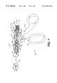
- FIG. 1is a broken partial section side view of an endoscopic electrocautery instrument according to a first embodiment of the present invention
- FIG. 2is a broken partial section side view of an endoscopic electrocautery instrument according to a second embodiment of the present invention
- FIG. 3is a broken partial section side view of an endoscopic electrocautery instrument according to a third embodiment of the present invention.
- FIG. 4is a cross-sectional view of a first pair of scissor blade members for use in the embodiments of FIGS. 1 through 3;
- FIG. 5is a cross-sectional view of a second pair of scissor blade members for use in the embodiments of FIGS. 1 through 3;
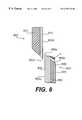
- FIG. 6is a cross-sectional view of a third pair of scissor blade members for use in the embodiments of FIGS. 1 through 3;
- FIG. 7is a cross-sectional view of a forth pair of scissor blade members for use in the embodiments of FIGS. 1 through 3;
- FIG. 8is a cross-sectional view of a fifth pair of scissor blade members for use in the embodiments of FIGS. 1 through 3;
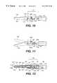
- FIGS. 9A and 9Bare views of a sixth scissor blade member for use in the embodiments of FIGS. 1 through 3;
- FIGS. 10 and 11are partial section views of a first blade member coupling arrangement for use in the embodiments of FIGS. 1 through 3;
- FIG. 12is a partial section top view of the first coupling arrangement of FIGS. 10 and 11;
- FIGS. 13 and 14are partial section views of a second blade member coupling arrangement for use in the embodiments of FIGS. 1 through 3;
- FIG. 15is a partial section top view of the second coupling arrangement of FIGS. 13 and 14;
- FIG. 16is a partial section view of a third clevis arrangement for use in the embodiments of FIGS. 1 through 3 .
- a first embodiment of an endoscopic electrocautery instrumentincludes a pair of end effector scissor blade members 102 , 104 a proximal actuator 106 , a hollow tube 108 , a clevis area 110 , and a rod assembly 112 extending through the tube.
- at least one of the blade members 102 , 104is rotatably mounted in the clevis area 110 about a screw 114 and coupled to the distal end of the rod assembly 112 .
- actuation of the actuator 106causes the scissor blade members 102 , 104 to move relative to one another to perform a cutting operation.
- the proximal actuator 106 of the instrument 100includes a fixed proximal handle 116 with a manual lever 118 pivotally coupled to the handle by a pivot pin 120 .
- the elongated, hollow tube 108is preferably made from stainless steel or other suitable material, and extends from the handle 118 to the clevis area 110 .
- the tube 108is preferably rotatably coupled about its longitudinal axis relative to the handle 116 through the use of a ferrule 122 such as described in detail in co-owned U.S. Pat. No. 5,569,243, the complete disclosure of which is herein incorporated by reference.
- the tube 108is preferably covered with an insulating sheath 124 along substantially its entire length from the ferrule 122 to the clevis area 110 .
- the rod assembly 112extends into the hollow tube 108 and is coupled at its proximal end 126 to the manual lever actuator 118 .
- the rod assembly 112includes a pair of rods 128 , 130 preferably made from stainless steel or any other suitably rigid material.
- Rod 130 of the rod assembly 112acts as a push rod for the scissor blade members 102 , 104 such that reciprocal movement of the rod assembly 112 relative to the tube 108 results in a scissor movement between the scissor blade members 102 , 104 , as shown for example in FIGS. 10 and 11.
- the reciprocal movement of the rod assembly 112 relative to the tube 108is affected by movement of the manual lever actuator 118 relative to the handle 116 .
- the rods 128 , 130have proximal ends 128 a , 130 a and distal ends 128 b , 130 b .
- the proximal ends 128 a , 130 a of the rodshave divergent bends which cause the rods to terminate in parallel proximal pins of an electric cautery connector 132 .
- the proximal ends of the rods, with the exception of the pins,are provided within a proximal collar 134 .
- the proximal collar 134has an increased diameter proximal portion 136 which accommodates the proximal bent portions 128 d , 130 d of the rods 128 , 130 and a radial protrusion 138 which is located distally of the increased diameter portion 136 .
- the radial protrusion 138 and the increased diameter portion 136form a recess 139 therebetween for receiving a coupling portion 141 of the actuator 118 .
- the proximal end of the collar 134is provided with a snap-together coupling for receiving the female electric cautery connector 132 . When assembled, the electric cautery connector 132 receives a standard male cautery plug (not shown).
- the proximal collar 134may be formed about the rods 128 , 130 by an injection molding process, but is preferably produced by placing the proximal ends 128 a , 130 a of rods 128 , 130 into open receiving grooves of a partially molded proximal collar and applying ultra violet curing material over the rods and grooves. The partially molded collar is then placed under ultra violet light so that the curing material quickly hardens to form the remaining portion of the proximal collar 134 .
- the distal end 128 b of the stainless steel rod 128terminates inside the hollow conductive tube 108 preferably at or near the proximal actuator 106 .
- End 128 bis swaged to make a wiping or sliding electrical contact with the conductive tube.
- the distal end 128 b of the rod 128will move relative to the tube 108 and will make a wiping connection.
- rod 128may terminate at any point along tube 108 prior to clevis area 110 .
- the distal end 130 b of the push rod 130is connected to blade members 102 , 104 so that axial movement of the push rod causes a scissor movement of the blade members 102 , 104 .
- the push rod 130is provided with an insulating sheath 140 from the clevis area 110 at the distal end 130 b to the proximal collar 134 . Sheath 140 ensures that push rod 130 is electrically isolated from rod 128 and tube 108 .
- the push rod 130is swaged at a point 130 c distal of the distal end 128 b of the rod 128 so that it assumes a substantially co-axial relationship with the tube 108 .
- the endoscopic electrocautery instrument of FIG. 1provides two cautery current paths to the scissor blade members 102 , 104 .
- the first pathtravels from the electric cautery connector 132 along the stainless steel rod 128 to the tube 108 and then across the clevis area 110 to at least one scissor blade member 102 , 104 .
- the second current pathflows from the electric cautery connector 132 to the push rod 130 and then to at least one scissor blade member via a coupling arrangement between the push rod 130 and scissor blade members 102 , 104 .
- the blade member coupling arrangement that permits the two cautery current pathswill be described in detail with reference to FIGS. 10 through 16 below.
- FIGS. 4 through 9also to be described below, detail the various embodiments of blade members for use in connection with the two cautery current paths to produce the desired cauterization at the surgery site.
- FIG. 2shows a second embodiment of an endoscopic electrocautery instrument according to the present invention.
- Instrument 200is similar to instrument 100 of FIG. 1 described above but with a different rod assembly 212 .
- the rod assembly 212includes a pair of rods 228 , 230 once again preferably made from stainless steel.
- Rods 228 , 230have proximal ends 228 a , 230 a and distal ends 228 b , 230 b .
- the proximal ends 228 a , 230 a of the rodshave divergent bends which cause the rods to terminate in parallel proximal pins.
- the proximal ends of the rodswith the exception of the pins, are provided with an over-molded proximal collar 134 which is substantially the same as described above with reference to FIG. 1 .
- the distal end 228 b of the first stainless steel rod 228terminates at a point proximal of the hollow conductive tube 108 and is connected to the hollow conductive tube 108 (preferably at the proximal end of the tube) by an extendable coiled wire or spring 242 .
- the connections between the wire 242 and the tube 108 , and the wire 242 and rod 228may be accomplished by soldering clips, or other secure fastening or connection arrangements known in the art.
- the push rod 230is preferably provided with an insulating sheath 240 from the clevis area 110 at the distal end thereof to the proximal collar 134 , and the push rod 230 is swaged at a point 230 c distal of the distal end 228 b of the rod 228 so that the push rod 230 assumes a substantially co-axial relationship with the tube 108 .
- the push rod 230is coupled to the scissor members 102 , 104 in a manner similar to that of the embodiment of FIG. 1 and to be described in detail below.
- the endoscopic electrocautery instrument of FIG. 2provides two cautery current paths to the scissor blade members 102 , 104 .
- the first current pathtravels from the electric cautery connector 132 along the stainless steel rod 228 to the extendable coiled wire or spring 242 to the tube 108 and then across the clevis area 110 to at least one of the scissor blade members.
- the lever 118is moved relative to the handle 116 , the rod assembly 212 will move relative to the tube 108 and the coiled wire or spring 242 will provide the necessary slack between the fixed proximal end of the tube 108 and the moving distal end 228 b of the rod 228 .
- the second cautery current pathis substantially the same as that described in relation to the embodiment of FIG. 1 .
- the tube 108 , scissor blade members 102 , 104 and push rod assembly 212are freely rotatable relative to the handle 116 and lever 118 via use of the ferrule assembly 122 , as described in previously incorporated co-owned U.S. Pat. No. 5,569,243.
- the endoscopic electrocautery instrument 300 of FIG. 3includes a manual actuator 306 having a non-conductive handle 316 including a stepped throughbore 344 and a lever 318 rotatably coupled to the handle 316 by a pivot pin 346 .
- the lever 318has an upper pinion gear 318 a which extends into the throughbore 344 .
- the elongated tube 308is fixedly coupled to a distal portion of the handle 316 about the throughbore 344 and extends to the clevis area 110 . Between the throughbore 344 and a distal end of the handle 316 , the tube 308 is contacted by a first electrical conductor 328 about the outer surface of the tube 308 .
- the exterior surface of the tube 308is preferably covered with an insulating sheath 309 along its length between the handle 316 and the clevis area 110 .
- the proximal end 330 a of the push rod 330is fixedly coupled by any suitable connection means to a slidable rack member 348 which is disposed in the throughbore 344 and is engaged by the pinion gear 318 a of the lever 318 .
- An expandable, electric conductor 350e.g. a spring or coil made of electrically conductive material
- the proximal end of the handle 316is provided with first and second electrical connectors 352 , 354 which are respectively coupled to the first and second conductors 328 , 350 .
- the distal end 330 b of the push rod 330extends into the clevis area 110 and is coupled to the scissor blade members 102 , 104 as described in detail below.
- the outer surface of the push rod 330is preferably covered with an insulating sheath 340 along substantially its entire length from the rack member 348 to its distal end 330 b .
- Rotation of the lever 318 relative to the handle 316causes reciprocal movement of the push rod 330 relative to the tube 308 to affect a scissor movement between scissor blade members 102 , 104 .
- the endoscopic electrocautery instrument of FIG. 3provides two cautery current paths to the scissor blade members 102 , 104 .
- the first pathtravels from the electric cautery connector 352 along the electric conductor 328 to the outer surface of the tube 308 and then across the clevis area 110 to at least one scissor blade member 102 , 104 .
- the second current pathflows from the electric cautery connector 354 to the expandable coil 350 , to the proximal end of the push rod 330 a located within the slide rack member 348 , and then to at least one scissor blade member via a coupling arrangement between the push rod 330 and the scissor blade members 102 , 104 .
- the non-conductive handle 316may be manufactured as two separate halves. Once the conductor 330 , the tube 308 , and the rack 348 are placed into one half of the handle, the two halves may be snapped, welded or otherwise coupled together.
- FIGS. 4 through 9detail various embodiments of scissor blade member configurations, the details of which are explained below. Each scissor blade configuration can be utilized in the endoscopic electrocautery instruments of FIGS. 1 through 3.
- a first set of scissor blade members 102 , 104is preferably composed of four layers: an inner conductive layer 156 , 158 , preferably formed of a superalloy or stainless steel, an intermediate non-conductive layer 160 , 162 , preferably epoxy or ceramic, an outer conductive layer 164 , 166 , preferably aluminum, and a non-conductive anodized aluminum layer 168 , 170 on the outer surface of the outer conductive layer.
- any of the first three mentioned layersmay be considered a primary substrate layer, although it is preferred that the substrate layer form the cutting edge of the blade.
- the primary substrate layerif either conductive layer were to be used as the primary substrate layer, a standard stainless steel or superalloy endoscopic scissor blade could be utilized for that layer.
- the intermediate non-conductive layeris to be used as the primary substrate layer, it is preferably formed from ceramic.
- Other conductive and non-conductive layer arrangementsare shown in co-owned U.S. patent application Ser. No. 08/354,992, the complete disclosure of which is herein incorporated by reference.
- the inner conductive layer 156 , 158forms an inner face of the scissor blade members 102 , 104 , a shearing surface 102 d , 104 d , and a cutting edge 102 c , 104 c .
- the outer conductive layer 164 , 166forms an outer layer of the scissor blade members 102 , 104 and is insulated from the first conductive layer by the intermediate non-conductive layer 160 , 162 .
- the outer conductive layer 164 , 166 of each blade memberis preferably made of aluminum which is “hard coated” or anodized to form the outer non-conductive layer 168 , 170 .
- Non-conductive layer 168 , 170has a relatively smaller thickness as compared to the outer layers and is shown in an exaggerated fashion in FIG. 4 .
- the outer non-conductive layer 168 , 170covers substantially all of the outer conductive layer 164 , 166 except for an end strip 164 b , 166 b which is closest to the cutting edge 102 c , 104 c and (as described in more detail below in relation to FIGS. 10-16) a portion in the vicinity of a scissor blade mounting hole.
- the exposed strip 164 b , 166 bis formed by grinding subsequent to anodizing.
- anodizingis a process which causes an oxidized layer to form on the surface of aluminum.
- the processis performed by placing aluminum in an aqueous bath containing salts which react with the aluminum to form Al 2 O 3 .
- the outer non-conductive layer formed by anodizingis typically about 0.001 to 0.004 inches thick.
- a cautery currentto the electrical connector 132 results in a first current being conducted from the push rod 130 to the inner conductive layers 156 , 158 of the blade members 102 , 104 and a second current of opposite polarity to the first current being conducted from push rod 128 to the tube 108 and to the outside layers 164 , 166 of the blade members.
- the structure used to apply such currentswill be described later with respect to FIGS. 10 to 16 .
- tissueWhen tissue is located between the cutting edge 102 c and the exposed end strip 164 b of the surface of the outer layer 164 of the blade member 102 as shown by the lines “e” (i.e., tissue which is in the process of being cut), current will flow through from one layer to the other through the tissue. Similarly, current will flow through tissue which is located between the cutting edge 104 c and the exposed end strip 166 b of the outer surface 166 of the blade 104 as shown by the lines “f”.
- the hard coating layers 168 , 170 on the outer conductive layers of the blade membersprevents an inadvertent cauterization of other tissues near the surgical site.
- a second set of blade members 502 , 504is substantially the same as the blade members 102 , 104 and will be described with reference numerals of similar elements increased by 400 .
- the blade members 502 , 504differ from the blade members 102 , 104 in that the substrate of each blade member is the intermediate non-conductive layer 560 , 562 which is preferably ceramic.
- Both the inner conductive layer 556 , 558 and the outer conductive layer 564 , 566 of the blade membersare preferably formed of deposited aluminum.
- the scissor blade members described thus fareach comprise four layers (including the layers formed by anodizing) and are substantially hermaphroditic, i.e. both blade members of a scissor instrument are substantially identical.
- aspects of the present inventionalso relate to scissor blade members having fewer than four layers and to scissor instruments which have two non-identical blade members. Further, the present invention also applies to curved scissor blade members.
- a third set of scissor blade membersare formed with non-identical blade members 602 , 604 each having one conductive layer and one non-conductive layer.
- the blade member 602has a non-conductive outer layer 672 and a conductive inner layer 674 defining a cutting edge 602 c and a shearing surface 602 d .
- the blade member 604has a conductive outer layer 676 and a non-conductive inner layer 678 defining a cutting edge 604 c and a shearing surface 604 d .
- the inner conductive layer 674 of the blade member 602makes electrical contact with a push rod having a first polarity and the outer conductive layer 676 of the blade member 604 makes electrical contact with an elongated tube on an endoscopic electrocautery instrument.
- Cautery currentflows through tissue located between the cutting edge 602 c and the shearing surface 602 d of the blade 602 and the upper portion of the outer layer 676 of the blade 604 as shown by the lines “g”.
- the scissor blade member arrangement shown in FIG. 6may be particularly useful in “single acting” endoscopic scissors (as further described in accordance with the description of FIG. 16 below).
- the scissor blade membersare shown in FIG. 6 as having a relatively thick non-conductive layer and a relatively thin conductive layer, the relative dimensions of the layers can vary depending on the materials used to fabricate the blade members. Any of the fabrication methods and materials described above can be used to manufacture the scissor blade members shown in FIG. 6 .
- a fourth set of scissor blade membersare formed with non-identical blade members 702 , 704 .
- the blade members 702 , 704are similar to the blade members 602 , 604 with the exception that an additional layer of alumina and titanium dioxide (Al 2 O 3 /TiO 2 ) or metal spray 780 is formed on the shearing surface 704 d of the non-conducting inner layer 778 .
- the alumina and titanium dioxide layerpreferably has a weight ratio of 60%/40% alumina to titanium dioxide.
- the additional layercan be applied in any known manner as disclosed in co-owned U.S. patent application Ser. No. 08/429,596, the complete disclosure of which is herein incorporated by reference.
- the additional layer 780(shown in an exaggerated fashion in FIG. 7) allows for improved machining of the cutting angle as compared to that of machining other non-conductive materials. Such improved machining allows for a sharper cutting edge 704 c and therefore a more effective cutting action of the scissor blade members. It will be appreciated by those skilled in the art that the additional layer of alumina and titanium dioxide or metal spray will provide the above benefits on any scissor blade member having a ceramic shearing surface.
- FIG. 8shows a fifth set of scissor blade members according to the present invention.
- the scissor blade member 802is substantially the same as scissor blade member 602 of the embodiment shown in FIG. 6, but m and scissor blade member 804 is similar to the scissor blade member 104 of the embodiment shown in FIG. 4 .
- the blade member 802has an outer non-conductive layer 872 and an inner conductive layer 874 that defines a cutting edge 802 c and a shearing surface 802 d .
- the blade member 804has an inner conductive layer 858 that defines a cutting edge 804 c and a shearing surface 804 d , an intermediate non-conductive layer 862 , and an outer conductive layer 866 .
- the outer conductive layer 866is anodized to form a non-conductive layer 870 which is ground along a portion 866 b to form an end strip adjacent to the cutting edge 804 c .
- the path of cautery currentflows along the path of least resistance from the cutting edge 804 c to the ground portion 866 b as shown by lines “h”.
- One significant difference between the blade members of FIG. 8 and the blade members of FIG. 6is that the blade members of FIG. 8 provide two metallic cutting edges and shearing surfaces. It is generally considered advantageous that the cutting edges and shearing surfaces of both blade members be metallic to provide for both a feel of conventional scissors during the cutting operation and the most effective cutting angle.
- Blade member 802being electrically connected to conductive layer 858 , assists cauterization by also allowing cautery current flow between outer conductive layer 866 and conductive layer 874 . Further, blade 802 can be formed of a single conductive material as long as cutting edge 802 c is only electrically connected to inner conductive layer 858 .
- FIGS. 9A and 9Billustrate a sixth scissor blade member design in accordance with the present invention.
- the scissor blade member 902includes an inner conductive aluminum layer 956 , an intermediate non-conductive layer 960 , and an outer conductive metallic layer 964 .
- the intermediate layer 960is preferably formed by anodizing or hard coating the surface of the aluminum layer 956 opposite a shearing surface 902 d .
- the desired cauterizationis affected by supplying a first current to the inner conductive layer 956 and a second current of opposite polarity to the outer conductive layer 964 .
- the two conductive layers 956 , 964 of the scissor blade member 902are interlocked together by a dovetail 964 a protruding from the outer conductive layer 964 into a corresponding groove 956 a of the inner conductive layer 956 .
- the dovetail 964 atapers outwardly from the inner surface of conductive layer 964 to the shearing surface 902 d of inner conductive layer 956 .
- Scissor blade member 902is secured at a proximal end adjacent a through hole 966 by a screw and clevis arrangement (described below).
- FIGS. 4 through 9are each capable of being coupled to any of the endoscopic electrocautery instruments of FIGS. 1 through 3.
- FIGS. 10 through 12depict a first embodiment of a coupling arrangement of the blade members 102 , 104 to the endoscopic electrocautery instrument 100 .
- each blade member 102 , 104includes a mounting hole 103 , 105 a tang 102 a , 104 a and an orthogonal boss 102 b , 104 b .
- These elementsconnect the blade members 102 , 104 with the clevis area 110 and the distal end of the push rod 130 to pivotally rotate the blade members relative to one another in response to movement of the lever 118 .
- the clevis area 110includes a pair of distally extending arms 110 a, 110 b.
- Each arm 110 a, 110 bhas an axle hole 110 c, 110 d for receiving a non-conductive screw 114 .
- the push rod 130extends through the tube 108 and into the space between the clevis arms 110 a , 110 b and includes a flattened end 182 defining a coupling hole 182 a .
- the tangs 102 a , 104 a of the blade membersPrior to mounting the scissor blade members 102 , 104 in the clevis arms 110 a and 110 b, the tangs 102 a , 104 a of the blade members are coupled to the flattened distal end 182 of the push rod 130 using conductive links 184 , 186 .
- the links 184 , 186have first and second holes 184 a , 184 b and 186 a , 186 b .
- the first holes 184 a , 186 aare coupled to the hole 182 a in the flattened end 182 of the push rod 130 by a rivet 188 .
- the second holes 184 b , 186 bare placed over bosses 102 b , 104 b which extend orthogonally from the tangs 102 a , 104 a of the scissor blade members 102 , 104 .
- Each boss 102 b , 104 bis located on the same layer of the scissor blade (i.e. the inner conductive layer 156 , 158 ) and is electrically coupled with the shearing surface. It will therefore be appreciated that inner conductive layer 156 , 158 of each blade member is electrically coupled to the conductive push rod 130 .
- the scissor blade members 102 , 104are mounted in the clevis arms 110 a , 110 b with their shearing surfaces 102 d , 104 d facing each other and with their mounting holes 103 , 105 aligned with the axle holes 110 c , 110 d of the clevis arms 110 a , 110 b.
- a non-conductive screw 114is inserted through the holes 110 c , 103 , 105 , and 110 d .
- each scissor blade in the vicinity of the mounting hole 103 , 105is left uncoated (or is ground to remove the hard coating) so that the outer conductive layer makes electrical contact with the conductive clevis arms 110 a, 110 b and is electrically coupled to the conductive tube 108 .
- FIGS. 13 through 15show a second embodiment of a coupling arrangement of the scissor blade members with the endoscopic electrocautery instrument of FIGS. 1 through 3.
- a conductive clevis area 210includes a clevis member 211 having a proximal cylindrical base 211 a, a pair of distally extending arms 211 b, 211 c and a bore 211 d extending through the base and opening into a space between the arms.
- Each arm 211 b, 211 cincludes an axle hole 211 e, 211 f for alignment with mounting holes 1503 , 1505 of blades 1502 and 1504 for receiving a non-conductive screw 214 therethrough.
- the clevis base 211 ais removably mounted within in the distal end 208 b of the tube 208 and makes electrical contact therewith.
- the push rod 130extends in a non-contacting manner through the bore 211 d of the clevis 211 and distally terminates with an uninsulated flattened end 282 located between the clevis arms 211 b, 211 c .
- the blade members 1502 , 1504are mounted to the clevis 211 via screw 214 and coupled to the flattened distal end 282 of the push rod 130 with links 284 , 286 . In this way, cautery current applied to push rod 130 will be conducted through the links 284 , 286 to the inner surfaces of blade members 1502 , 1504 .
- clevis 211reduces the amount of space in the area of links 284 , 286 . Because of such reduced space, the blade members 1502 , 1504 can be configured to couple with links 284 , 286 about an inner surface 1502 d , 1504 d of an inner layer 1556 , 1558 of the blades 1502 , 1504 , rather than about an outer surface of an inner layer of blades 102 , 104 of the embodiment shown in FIGS. 10 through 12. Further, the interior surface of clevis 211 in the vicinity of the links 284 , 286 may be insulated by anodizing or otherwise coating. Such a coating reduces short circuiting caused by contact of the links 284 , 286 with the interior surfaces of the clevis 211 .
- FIG. 16shows a third embodiment of a coupling arrangement of scissor blade members for use with the endoscopic electrocautery instruments of FIGS. 1 through 3.
- This arrangementincorporates a “single acting” blade configuration, wherein one blade member 1602 is fixed and the other blade member 1604 is actuated to rotate relative to the fixed blade member 1602 .
- the fixed blade member 1602is connected to the elongated tube 108 in any suitable manner, such as via a securing boss on fixed blade member 1602 in conjunction with a screw and boss receiving clevis, or integrally formed with the tube 108 .
- Rotating blade member 1604is rotatable about an insulated screw 1614 located in mounting holes 1690 , 1692 of the rotating blade member 1604 and the fixed blade member 1602 or a clevis.
- the rotating blade member 1614is coupled to a push rod in any of the manners previously described with reference to FIGS. 10-15 (as exemplified in phantom lines in the figure) and can be electrically connected to cautery current by way of the push rod and/or swiping contact with tube 108 . Any of the blade configurations described with regard to FIGS. 4-9 may be used with this embodiment.
- the coupling arrangement of FIG. 16allows cautery current of a first polarity to travel from the push rod 130 to the rotating blade member 1604 and cautery current of an opposite polarity to flow from the tube 108 to the fixed blade member 1602 .
- Such an arrangementreduces the required number of parts over those instruments having two moving blade members.
- such a “single acting” coupling arrangement herein describedmay be utilized in endoscopic electrocautery instruments having end effectors other than scissor blade members, for example, instruments having end effectors formed as graspers, jaws, or the like.
Landscapes
- Health & Medical Sciences (AREA)
- Surgery (AREA)
- Engineering & Computer Science (AREA)
- Life Sciences & Earth Sciences (AREA)
- Biomedical Technology (AREA)
- Otolaryngology (AREA)
- Nuclear Medicine, Radiotherapy & Molecular Imaging (AREA)
- Plasma & Fusion (AREA)
- Physics & Mathematics (AREA)
- Heart & Thoracic Surgery (AREA)
- Medical Informatics (AREA)
- Molecular Biology (AREA)
- Animal Behavior & Ethology (AREA)
- General Health & Medical Sciences (AREA)
- Public Health (AREA)
- Veterinary Medicine (AREA)
- Surgical Instruments (AREA)
Abstract
Description
Claims (39)
Priority Applications (1)
| Application Number | Priority Date | Filing Date | Title |
|---|---|---|---|
| US09/095,307US6193718B1 (en) | 1998-06-10 | 1998-06-10 | Endoscopic electrocautery instrument |
Applications Claiming Priority (1)
| Application Number | Priority Date | Filing Date | Title |
|---|---|---|---|
| US09/095,307US6193718B1 (en) | 1998-06-10 | 1998-06-10 | Endoscopic electrocautery instrument |
Publications (1)
| Publication Number | Publication Date |
|---|---|
| US6193718B1true US6193718B1 (en) | 2001-02-27 |
Family
ID=22251299
Family Applications (1)
| Application Number | Title | Priority Date | Filing Date |
|---|---|---|---|
| US09/095,307Expired - Fee RelatedUS6193718B1 (en) | 1998-06-10 | 1998-06-10 | Endoscopic electrocautery instrument |
Country Status (1)
| Country | Link |
|---|---|
| US (1) | US6193718B1 (en) |
Cited By (178)
| Publication number | Priority date | Publication date | Assignee | Title |
|---|---|---|---|---|
| US6298550B1 (en)* | 1997-06-26 | 2001-10-09 | Kirwan Surgical Products, Inc. | Process for manufacturing electro-surgical forceps which minimizes or prevents sticking of tissue |
| US6391029B1 (en)* | 1995-03-07 | 2002-05-21 | Enable Medical Corporation | Bipolar electrosurgical scissors |
| US6464701B1 (en)* | 1995-03-07 | 2002-10-15 | Enable Medical Corporation | Bipolar electrosurgical scissors |
| US20030014052A1 (en)* | 1997-11-14 | 2003-01-16 | Buysse Steven P. | Laparoscopic bipolar electrosurgical instrument |
| US20030018331A1 (en)* | 2001-04-06 | 2003-01-23 | Dycus Sean T. | Vessel sealer and divider |
| US20030018332A1 (en)* | 2001-06-20 | 2003-01-23 | Schmaltz Dale Francis | Bipolar electrosurgical instrument with replaceable electrodes |
| US6558384B2 (en)* | 1998-12-03 | 2003-05-06 | Aesculap Ag & Co. Kg | Surgical bipolar scissors |
| US20030181910A1 (en)* | 1998-10-23 | 2003-09-25 | Dycus Sean T. | Bipolar electrosurgical forceps with non-conductive stop members |
| US20030199869A1 (en)* | 1998-10-23 | 2003-10-23 | Johnson Kristin D. | Vessel sealing instrument |
| US20030229344A1 (en)* | 2002-01-22 | 2003-12-11 | Dycus Sean T. | Vessel sealer and divider and method of manufacturing same |
| US20040082952A1 (en)* | 2001-04-06 | 2004-04-29 | Dycus Sean T. | Vessel sealer and divider |
| US20040087943A1 (en)* | 2001-04-06 | 2004-05-06 | Dycus Sean T. | Vessel sealer an divider |
| US20040115296A1 (en)* | 2002-04-05 | 2004-06-17 | Duffin Terry M. | Retractable overmolded insert retention apparatus |
| US20040122423A1 (en)* | 2001-04-06 | 2004-06-24 | Dycus Sean T. | Vessel sealer and divider with non-conductive stop members |
| US20040147925A1 (en)* | 1997-11-12 | 2004-07-29 | Buysse Steven P | Bipolar electrosurgical instrument for sealing vessels |
| US20040162557A1 (en)* | 1998-10-23 | 2004-08-19 | Tetzlaff Philip M. | Vessel sealing instrument |
| US20040176762A1 (en)* | 1997-11-12 | 2004-09-09 | Lawes Kate R. | Electrosurgical instrument reducing flashover |
| US20040193153A1 (en)* | 2001-04-06 | 2004-09-30 | Sartor Joe Don | Molded insulating hinge for bipolar instruments |
| US20040225288A1 (en)* | 1997-11-12 | 2004-11-11 | Buysse Steven Paul | Bipolar electrosurgical instrument for sealing vessels |
| US20040243125A1 (en)* | 2001-04-06 | 2004-12-02 | Sean Dycus | Vessel sealer and divider |
| US20040249374A1 (en)* | 1998-10-23 | 2004-12-09 | Tetzlaff Philip M. | Vessel sealing instrument |
| US20040250419A1 (en)* | 2003-06-13 | 2004-12-16 | Sremcich Paul S. | Method of manufacturing jaw assembly for vessel sealer and divider |
| US20040260338A1 (en)* | 2003-06-20 | 2004-12-23 | Aesculap Ag & Co. Kg | Surgical instrument |
| US20050004568A1 (en)* | 1997-11-12 | 2005-01-06 | Lawes Kate R. | Electrosurgical instrument reducing thermal spread |
| US20050004571A1 (en)* | 2003-07-03 | 2005-01-06 | Select Medizin-Technik Hermann Sutter Gmbh | Bipolar tubular shaft instrument |
| US20050004570A1 (en)* | 2003-05-01 | 2005-01-06 | Chapman Troy J. | Electrosurgical instrument which reduces thermal damage to adjacent tissue |
| US20050021027A1 (en)* | 2003-05-15 | 2005-01-27 | Chelsea Shields | Tissue sealer with non-conductive variable stop members and method of sealing tissue |
| US20050021026A1 (en)* | 2003-05-01 | 2005-01-27 | Ali Baily | Method of fusing biomaterials with radiofrequency energy |
| US20050021025A1 (en)* | 1997-11-12 | 2005-01-27 | Buysse Steven P. | Electrosurgical instruments which reduces collateral damage to adjacent tissue |
| US6887240B1 (en) | 1995-09-19 | 2005-05-03 | Sherwood Services Ag | Vessel sealing wave jaw |
| US20050101952A1 (en)* | 1999-10-18 | 2005-05-12 | Lands Michael J. | Vessel sealing wave jaw |
| US20050107784A1 (en)* | 2003-11-19 | 2005-05-19 | Moses Michael C. | Open vessel sealing instrument with cutting mechanism and distal lockout |
| US20050107785A1 (en)* | 2003-06-13 | 2005-05-19 | Dycus Sean T. | Vessel sealer and divider having elongated knife stroke and safety for cutting mechanism |
| US20050107860A1 (en)* | 2003-07-23 | 2005-05-19 | Ignagni Anthony R. | Mapping probe system for neuromuscular electrical stimulation apparatus |
| US20050113826A1 (en)* | 2002-10-04 | 2005-05-26 | Johnson Kristin D. | Vessel sealing instrument with electrical cutting mechanism |
| US20050113827A1 (en)* | 2003-11-17 | 2005-05-26 | Dumbauld Patrick L. | Bipolar forceps having monopolar extension |
| US20050113828A1 (en)* | 2003-11-20 | 2005-05-26 | Chelsea Shields | Electrically conductive/insulative over-shoe for tissue fusion |
| US20050119655A1 (en)* | 2003-11-19 | 2005-06-02 | Moses Michael C. | Open vessel sealing instrument with cutting mechanism |
| US6932810B2 (en) | 1997-09-09 | 2005-08-23 | Sherwood Services Ag | Apparatus and method for sealing and cutting tissue |
| US20050186440A1 (en)* | 2004-02-19 | 2005-08-25 | Karlheinz Hausmann | Flame retardant surface coverings |
| US6960210B2 (en) | 1997-11-14 | 2005-11-01 | Sherwood Services Ag | Laparoscopic bipolar electrosurgical instrument |
| US20060052777A1 (en)* | 2004-09-09 | 2006-03-09 | Dumbauld Patrick L | Forceps with spring loaded end effector assembly |
| US20060052779A1 (en)* | 2003-03-13 | 2006-03-09 | Hammill Curt D | Electrode assembly for tissue fusion |
| US20060064086A1 (en)* | 2003-03-13 | 2006-03-23 | Darren Odom | Bipolar forceps with multiple electrode array end effector assembly |
| US20060074417A1 (en)* | 2003-11-19 | 2006-04-06 | Cunningham James S | Spring loaded reciprocating tissue cutting mechanism in a forceps-style electrosurgical instrument |
| US20060079890A1 (en)* | 2004-10-08 | 2006-04-13 | Paul Guerra | Bilateral foot jaws |
| US20060084973A1 (en)* | 2004-10-14 | 2006-04-20 | Dylan Hushka | Momentary rocker switch for use with vessel sealing instruments |
| US7033354B2 (en) | 2002-12-10 | 2006-04-25 | Sherwood Services Ag | Electrosurgical electrode having a non-conductive porous ceramic coating |
| US20060089670A1 (en)* | 2004-10-21 | 2006-04-27 | Dylan Hushka | Magnetic closure mechanism for hemostat |
| USD525361S1 (en) | 2004-10-06 | 2006-07-18 | Sherwood Services Ag | Hemostat style elongated dissecting and dividing instrument |
| US20060167452A1 (en)* | 2005-01-14 | 2006-07-27 | Moses Michael C | Open vessel sealing instrument |
| US7083618B2 (en) | 2001-04-06 | 2006-08-01 | Sherwood Services Ag | Vessel sealer and divider |
| US7101373B2 (en) | 2001-04-06 | 2006-09-05 | Sherwood Services Ag | Vessel sealer and divider |
| US20060217709A1 (en)* | 2003-05-01 | 2006-09-28 | Sherwood Services Ag | Electrosurgical instrument that directs energy delivery and protects adjacent tissue |
| US20060224158A1 (en)* | 2005-03-31 | 2006-10-05 | Darren Odom | Electrosurgical forceps with slow closure sealing plates and method of sealing tissue |
| US7118570B2 (en) | 2001-04-06 | 2006-10-10 | Sherwood Services Ag | Vessel sealing forceps with disposable electrodes |
| USD531311S1 (en) | 2004-10-06 | 2006-10-31 | Sherwood Services Ag | Pistol grip style elongated dissecting and dividing instrument |
| USD533942S1 (en) | 2004-06-30 | 2006-12-19 | Sherwood Services Ag | Open vessel sealer with mechanical cutter |
| US7156846B2 (en) | 2003-06-13 | 2007-01-02 | Sherwood Services Ag | Vessel sealer and divider for use with small trocars and cannulas |
| USD535027S1 (en) | 2004-10-06 | 2007-01-09 | Sherwood Services Ag | Low profile vessel sealing and cutting mechanism |
| US20070016187A1 (en)* | 2005-07-13 | 2007-01-18 | Craig Weinberg | Switch mechanisms for safe activation of energy on an electrosurgical instrument |
| US20070078459A1 (en)* | 2005-09-30 | 2007-04-05 | Sherwood Services Ag | Flexible endoscopic catheter with ligasure |
| US20070078458A1 (en)* | 2005-09-30 | 2007-04-05 | Dumbauld Patrick L | Insulating boot for electrosurgical forceps |
| USD541418S1 (en) | 2004-10-06 | 2007-04-24 | Sherwood Services Ag | Lung sealing device |
| USD541938S1 (en) | 2004-04-09 | 2007-05-01 | Sherwood Services Ag | Open vessel sealer with mechanical cutter |
| US20070106297A1 (en)* | 2005-09-30 | 2007-05-10 | Dumbauld Patrick L | In-line vessel sealer and divider |
| US20070106295A1 (en)* | 2005-09-30 | 2007-05-10 | Garrison David M | Insulating boot for electrosurgical forceps |
| US20070142833A1 (en)* | 2003-06-13 | 2007-06-21 | Dycus Sean T | Vessel sealer and divider having elongated knife stroke and safety for cutting mechanism |
| US20070156139A1 (en)* | 2003-03-13 | 2007-07-05 | Schechter David A | Bipolar concentric electrode assembly for soft tissue fusion |
| US20070173814A1 (en)* | 2006-01-24 | 2007-07-26 | David Hixson | Vessel sealer and divider for large tissue structures |
| US7270664B2 (en) | 2002-10-04 | 2007-09-18 | Sherwood Services Ag | Vessel sealing instrument with electrical cutting mechanism |
| US20070244510A1 (en)* | 2006-04-14 | 2007-10-18 | Ethicon Endo-Surgery, Inc. | Endoscopic device |
| US20070244512A1 (en)* | 2006-04-14 | 2007-10-18 | Ethicon Endo-Surgery, Inc. | Endoscopic device |
| US20070244514A1 (en)* | 2006-04-14 | 2007-10-18 | Ethicon Endo-Surgery, Inc. | End effector and method of manufacture |
| US20070260241A1 (en)* | 2006-05-04 | 2007-11-08 | Sherwood Services Ag | Open vessel sealing forceps disposable handswitch |
| US20070260235A1 (en)* | 2006-05-05 | 2007-11-08 | Sherwood Services Ag | Apparatus and method for electrode thermosurgery |
| US20080015575A1 (en)* | 2006-07-14 | 2008-01-17 | Sherwood Services Ag | Vessel sealing instrument with pre-heated electrodes |
| US20080021450A1 (en)* | 2006-07-18 | 2008-01-24 | Sherwood Services Ag | Apparatus and method for transecting tissue on a bipolar vessel sealing instrument |
| US20080027427A1 (en)* | 2006-07-27 | 2008-01-31 | Applied Medical Resources Corporation | Bipolar electrosurgical scissors |
| USD564662S1 (en) | 2004-10-13 | 2008-03-18 | Sherwood Services Ag | Hourglass-shaped knife for electrosurgical forceps |
| US20080091189A1 (en)* | 2006-10-17 | 2008-04-17 | Tyco Healthcare Group Lp | Ablative material for use with tissue treatment device |
| USD567943S1 (en) | 2004-10-08 | 2008-04-29 | Sherwood Services Ag | Over-ratchet safety for a vessel sealing instrument |
| US7367976B2 (en) | 2003-11-17 | 2008-05-06 | Sherwood Services Ag | Bipolar forceps having monopolar extension |
| US7384421B2 (en) | 2004-10-06 | 2008-06-10 | Sherwood Services Ag | Slide-activated cutting assembly |
| US20080195093A1 (en)* | 2002-10-04 | 2008-08-14 | Tyco Healthcare Group Lp | Vessel sealing instrument with electrical cutting mechanism |
| USD575395S1 (en) | 2007-02-15 | 2008-08-19 | Tyco Healthcare Group Lp | Hemostat style elongated dissecting and dividing instrument |
| USD575401S1 (en) | 2007-06-12 | 2008-08-19 | Tyco Healthcare Group Lp | Vessel sealer |
| US20090018535A1 (en)* | 2004-09-21 | 2009-01-15 | Schechter David A | Articulating bipolar electrosurgical instrument |
| US7510556B2 (en) | 1998-10-23 | 2009-03-31 | Coviden Ag | Vessel sealing instrument |
| US20090088744A1 (en)* | 2007-09-28 | 2009-04-02 | Tyco Healthcare Group Lp | Insulating Boot for Electrosurgical Forceps With Thermoplastic Clevis |
| US20090088750A1 (en)* | 2007-09-28 | 2009-04-02 | Tyco Healthcare Group Lp | Insulating Boot with Silicone Overmold for Electrosurgical Forceps |
| JP2009178559A (en)* | 2008-01-31 | 2009-08-13 | Tyco Healthcare Group Lp | Bipolar scissors for adenoid and tonsil removal |
| US7594916B2 (en) | 2005-11-22 | 2009-09-29 | Covidien Ag | Electrosurgical forceps with energy based tissue division |
| US7597693B2 (en) | 2003-06-13 | 2009-10-06 | Covidien Ag | Vessel sealer and divider for use with small trocars and cannulas |
| US7628791B2 (en) | 2005-08-19 | 2009-12-08 | Covidien Ag | Single action tissue sealer |
| US20100042142A1 (en)* | 2008-08-15 | 2010-02-18 | Cunningham James S | Method of Transferring Pressure in an Articulating Surgical Instrument |
| US20100057084A1 (en)* | 2008-08-28 | 2010-03-04 | TYCO Healthcare Group L.P | Tissue Fusion Jaw Angle Improvement |
| US20100057082A1 (en)* | 2008-08-28 | 2010-03-04 | Tyco Healthcare Group Lp | Tissue Fusion Jaw Angle Improvement |
| US20100063500A1 (en)* | 2008-09-05 | 2010-03-11 | Tyco Healthcare Group Lp | Apparatus, System and Method for Performing an Electrosurgical Procedure |
| US20100069953A1 (en)* | 2008-09-16 | 2010-03-18 | Tyco Healthcare Group Lp | Method of Transferring Force Using Flexible Fluid-Filled Tubing in an Articulating Surgical Instrument |
| US7686804B2 (en) | 2005-01-14 | 2010-03-30 | Covidien Ag | Vessel sealer and divider with rotating sealer and cutter |
| US20100087818A1 (en)* | 2008-10-03 | 2010-04-08 | Tyco Healthcare Group Lp | Method of Transferring Rotational Motion in an Articulating Surgical Instrument |
| US20100094286A1 (en)* | 2008-10-09 | 2010-04-15 | Tyco Healthcare Group Lp | Apparatus, System, and Method for Performing an Electrosurgical Procedure |
| US20100145334A1 (en)* | 2008-12-10 | 2010-06-10 | Tyco Healthcare Group Lp | Vessel Sealer and Divider |
| US20100179547A1 (en)* | 2009-01-14 | 2010-07-15 | Tyco Healthcare Group Lp | Apparatus, System, and Method for Performing an Electrosurgical Procedure |
| US7776037B2 (en) | 2006-07-07 | 2010-08-17 | Covidien Ag | System and method for controlling electrode gap during tissue sealing |
| US7789878B2 (en) | 2005-09-30 | 2010-09-07 | Covidien Ag | In-line vessel sealer and divider |
| US7799026B2 (en) | 2002-11-14 | 2010-09-21 | Covidien Ag | Compressible jaw configuration with bipolar RF output electrodes for soft tissue fusion |
| US7811283B2 (en) | 2003-11-19 | 2010-10-12 | Covidien Ag | Open vessel sealing instrument with hourglass cutting mechanism and over-ratchet safety |
| US7877852B2 (en) | 2007-09-20 | 2011-02-01 | Tyco Healthcare Group Lp | Method of manufacturing an end effector assembly for sealing tissue |
| US7877853B2 (en) | 2007-09-20 | 2011-02-01 | Tyco Healthcare Group Lp | Method of manufacturing end effector assembly for sealing tissue |
| US7922953B2 (en) | 2005-09-30 | 2011-04-12 | Covidien Ag | Method for manufacturing an end effector assembly |
| US7955332B2 (en) | 2004-10-08 | 2011-06-07 | Covidien Ag | Mechanism for dividing tissue in a hemostat-style instrument |
| US20110245825A1 (en)* | 2010-04-01 | 2011-10-06 | Lothar Mitzlaff | Surgical instrument, particularly electrosurgical instrument |
| CN102225026A (en)* | 2011-06-27 | 2011-10-26 | 申屠丙花 | Bipolar electric coagulation surgical scissors |
| USD649249S1 (en) | 2007-02-15 | 2011-11-22 | Tyco Healthcare Group Lp | End effectors of an elongated dissecting and dividing instrument |
| US8070746B2 (en) | 2006-10-03 | 2011-12-06 | Tyco Healthcare Group Lp | Radiofrequency fusion of cardiac tissue |
| US8211105B2 (en) | 1997-11-12 | 2012-07-03 | Covidien Ag | Electrosurgical instrument which reduces collateral damage to adjacent tissue |
| US8235993B2 (en) | 2007-09-28 | 2012-08-07 | Tyco Healthcare Group Lp | Insulating boot for electrosurgical forceps with exohinged structure |
| US8236025B2 (en) | 2007-09-28 | 2012-08-07 | Tyco Healthcare Group Lp | Silicone insulated electrosurgical forceps |
| US8235992B2 (en) | 2007-09-28 | 2012-08-07 | Tyco Healthcare Group Lp | Insulating boot with mechanical reinforcement for electrosurgical forceps |
| US8241282B2 (en) | 2006-01-24 | 2012-08-14 | Tyco Healthcare Group Lp | Vessel sealing cutting assemblies |
| US8241283B2 (en) | 2007-09-28 | 2012-08-14 | Tyco Healthcare Group Lp | Dual durometer insulating boot for electrosurgical forceps |
| US8251996B2 (en) | 2007-09-28 | 2012-08-28 | Tyco Healthcare Group Lp | Insulating sheath for electrosurgical forceps |
| US8257387B2 (en) | 2008-08-15 | 2012-09-04 | Tyco Healthcare Group Lp | Method of transferring pressure in an articulating surgical instrument |
| US8267936B2 (en) | 2007-09-28 | 2012-09-18 | Tyco Healthcare Group Lp | Insulating mechanically-interfaced adhesive for electrosurgical forceps |
| US8267935B2 (en) | 2007-04-04 | 2012-09-18 | Tyco Healthcare Group Lp | Electrosurgical instrument reducing current densities at an insulator conductor junction |
| US8298232B2 (en) | 2006-01-24 | 2012-10-30 | Tyco Healthcare Group Lp | Endoscopic vessel sealer and divider for large tissue structures |
| US8303582B2 (en) | 2008-09-15 | 2012-11-06 | Tyco Healthcare Group Lp | Electrosurgical instrument having a coated electrode utilizing an atomic layer deposition technique |
| US8317787B2 (en) | 2008-08-28 | 2012-11-27 | Covidien Lp | Tissue fusion jaw angle improvement |
| US8348948B2 (en) | 2004-03-02 | 2013-01-08 | Covidien Ag | Vessel sealing system using capacitive RF dielectric heating |
| US8361071B2 (en) | 1999-10-22 | 2013-01-29 | Covidien Ag | Vessel sealing forceps with disposable electrodes |
| USD680220S1 (en) | 2012-01-12 | 2013-04-16 | Coviden IP | Slider handle for laparoscopic device |
| US8454602B2 (en) | 2009-05-07 | 2013-06-04 | Covidien Lp | Apparatus, system, and method for performing an electrosurgical procedure |
| US8469957B2 (en) | 2008-10-07 | 2013-06-25 | Covidien Lp | Apparatus, system, and method for performing an electrosurgical procedure |
| US8469956B2 (en) | 2008-07-21 | 2013-06-25 | Covidien Lp | Variable resistor jaw |
| US8486107B2 (en) | 2008-10-20 | 2013-07-16 | Covidien Lp | Method of sealing tissue using radiofrequency energy |
| US8523898B2 (en) | 2009-07-08 | 2013-09-03 | Covidien Lp | Endoscopic electrosurgical jaws with offset knife |
| US8535312B2 (en) | 2008-09-25 | 2013-09-17 | Covidien Lp | Apparatus, system and method for performing an electrosurgical procedure |
| US8591506B2 (en) | 1998-10-23 | 2013-11-26 | Covidien Ag | Vessel sealing system |
| US8597297B2 (en) | 2006-08-29 | 2013-12-03 | Covidien Ag | Vessel sealing instrument with multiple electrode configurations |
| US8623276B2 (en) | 2008-02-15 | 2014-01-07 | Covidien Lp | Method and system for sterilizing an electrosurgical instrument |
| US8636761B2 (en) | 2008-10-09 | 2014-01-28 | Covidien Lp | Apparatus, system, and method for performing an endoscopic electrosurgical procedure |
| US8734443B2 (en) | 2006-01-24 | 2014-05-27 | Covidien Lp | Vessel sealer and divider for large tissue structures |
| US8764748B2 (en) | 2008-02-06 | 2014-07-01 | Covidien Lp | End effector assembly for electrosurgical device and method for making the same |
| US8852228B2 (en) | 2009-01-13 | 2014-10-07 | Covidien Lp | Apparatus, system, and method for performing an electrosurgical procedure |
| US8882766B2 (en) | 2006-01-24 | 2014-11-11 | Covidien Ag | Method and system for controlling delivery of energy to divide tissue |
| US8898888B2 (en) | 2009-09-28 | 2014-12-02 | Covidien Lp | System for manufacturing electrosurgical seal plates |
| US8968314B2 (en) | 2008-09-25 | 2015-03-03 | Covidien Lp | Apparatus, system and method for performing an electrosurgical procedure |
| US9023043B2 (en) | 2007-09-28 | 2015-05-05 | Covidien Lp | Insulating mechanically-interfaced boot and jaws for electrosurgical forceps |
| US9028493B2 (en) | 2009-09-18 | 2015-05-12 | Covidien Lp | In vivo attachable and detachable end effector assembly and laparoscopic surgical instrument and methods therefor |
| US9113940B2 (en) | 2011-01-14 | 2015-08-25 | Covidien Lp | Trigger lockout and kickback mechanism for surgical instruments |
| US20150320484A1 (en)* | 2014-05-09 | 2015-11-12 | Getac Technology Corporation | Operation handles for electrocautery |
| US9375254B2 (en) | 2008-09-25 | 2016-06-28 | Covidien Lp | Seal and separate algorithm |
| US20170056098A1 (en)* | 2013-03-18 | 2017-03-02 | Intuitive Surgical Operations, Inc. | Surgical instrument drive element, and related devices, systems, and methods |
| US9603652B2 (en) | 2008-08-21 | 2017-03-28 | Covidien Lp | Electrosurgical instrument including a sensor |
| WO2017198671A1 (en)* | 2016-05-17 | 2017-11-23 | Creo Medical Limited | Electrosurgical cutting tool |
| US9827140B2 (en) | 2013-07-17 | 2017-11-28 | William Thomas McClellan | Percutaneous blepharoplasty device and method |
| US9848938B2 (en) | 2003-11-13 | 2017-12-26 | Covidien Ag | Compressible jaw configuration with bipolar RF output electrodes for soft tissue fusion |
| US9987078B2 (en) | 2015-07-22 | 2018-06-05 | Covidien Lp | Surgical forceps |
| US10213250B2 (en) | 2015-11-05 | 2019-02-26 | Covidien Lp | Deployment and safety mechanisms for surgical instruments |
| US10231777B2 (en) | 2014-08-26 | 2019-03-19 | Covidien Lp | Methods of manufacturing jaw members of an end-effector assembly for a surgical instrument |
| US10631918B2 (en) | 2015-08-14 | 2020-04-28 | Covidien Lp | Energizable surgical attachment for a mechanical clamp |
| US10646267B2 (en) | 2013-08-07 | 2020-05-12 | Covidien LLP | Surgical forceps |
| US20200222112A1 (en)* | 2017-10-13 | 2020-07-16 | Creo Medical Limited | Electrosurgical resector tool |
| US10835309B1 (en) | 2002-06-25 | 2020-11-17 | Covidien Ag | Vessel sealer and divider |
| US10856933B2 (en) | 2016-08-02 | 2020-12-08 | Covidien Lp | Surgical instrument housing incorporating a channel and methods of manufacturing the same |
| US20210038293A1 (en)* | 2009-10-30 | 2021-02-11 | Covidien Lp | Jaw roll joint |
| US10918407B2 (en) | 2016-11-08 | 2021-02-16 | Covidien Lp | Surgical instrument for grasping, treating, and/or dividing tissue |
| US10987159B2 (en) | 2015-08-26 | 2021-04-27 | Covidien Lp | Electrosurgical end effector assemblies and electrosurgical forceps configured to reduce thermal spread |
| WO2021105131A1 (en)* | 2019-11-28 | 2021-06-03 | Creo Medical Ltd | Electrosurgical resector tool |
| US11090050B2 (en) | 2019-09-03 | 2021-08-17 | Covidien Lp | Trigger mechanisms for surgical instruments and surgical instruments including the same |
| US20210251680A1 (en)* | 2020-02-13 | 2021-08-19 | Covidien Lp | Low profile single pole tip for bipolar pencil |
| CN113384306A (en)* | 2020-03-11 | 2021-09-14 | 杭州安杰思医学科技股份有限公司 | Bipolar electric treatment device |
| US11166759B2 (en) | 2017-05-16 | 2021-11-09 | Covidien Lp | Surgical forceps |
| RU2775542C2 (en)* | 2017-10-13 | 2022-07-04 | Крео Медикал Лимитед | Electrosurgical resector instrument |
| USD956973S1 (en) | 2003-06-13 | 2022-07-05 | Covidien Ag | Movable handle for endoscopic vessel sealer and divider |
| US20230329776A1 (en)* | 2016-04-15 | 2023-10-19 | Bolder Surgical, Llc | Electrosurgical sealer and divider |
Citations (27)
| Publication number | Priority date | Publication date | Assignee | Title |
|---|---|---|---|---|
| US2002594A (en) | 1933-03-24 | 1935-05-28 | Wappler Frederick Charles | Instrument for electro-surgical treatment of tissue |
| US2200322A (en) | 1936-08-15 | 1940-05-14 | Walter A Arnesen | Cautery handle |
| US5114423A (en)* | 1989-05-15 | 1992-05-19 | Advanced Cardiovascular Systems, Inc. | Dilatation catheter assembly with heated balloon |
| US5258006A (en) | 1992-08-21 | 1993-11-02 | Everest Medical Corporation | Bipolar electrosurgical forceps |
| EP0572131A1 (en) | 1992-05-21 | 1993-12-01 | Everest Medical Corporation | Surgical scissors with bipolar coagulation feature |
| US5330471A (en) | 1991-06-07 | 1994-07-19 | Hemostatic Surgery Corporation | Bi-polar electrosurgical endoscopic instruments and methods of use |
| US5342381A (en) | 1993-02-11 | 1994-08-30 | Everest Medical Corporation | Combination bipolar scissors and forceps instrument |
| US5352222A (en) | 1994-03-15 | 1994-10-04 | Everest Medical Corporation | Surgical scissors with bipolar coagulation feature |
| US5356408A (en) | 1993-07-16 | 1994-10-18 | Everest Medical Corporation | Bipolar electrosurgical scissors having nonlinear blades |
| US5391166A (en) | 1991-06-07 | 1995-02-21 | Hemostatic Surgery Corporation | Bi-polar electrosurgical endoscopic instruments having a detachable working end |
| US5395369A (en) | 1993-06-10 | 1995-03-07 | Symbiosis Corporation | Endoscopic bipolar electrocautery instruments |
| US5396900A (en)* | 1991-04-04 | 1995-03-14 | Symbiosis Corporation | Endoscopic end effectors constructed from a combination of conductive and non-conductive materials and useful for selective endoscopic cautery |
| US5423814A (en) | 1992-05-08 | 1995-06-13 | Loma Linda University Medical Center | Endoscopic bipolar coagulation device |
| US5456684A (en) | 1994-09-08 | 1995-10-10 | Hutchinson Technology Incorporated | Multifunctional minimally invasive surgical instrument |
| US5462546A (en) | 1993-02-05 | 1995-10-31 | Everest Medical Corporation | Bipolar electrosurgical forceps |
| US5496317A (en) | 1993-05-04 | 1996-03-05 | Gyrus Medical Limited | Laparoscopic surgical instrument |
| US5514134A (en) | 1993-02-05 | 1996-05-07 | Everest Medical Corporation | Bipolar electrosurgical scissors |
| EP0717966A1 (en) | 1994-12-21 | 1996-06-26 | Gyrus Medical Limited | Electrosurgical bipolar scissors |
| US5540685A (en) | 1995-01-06 | 1996-07-30 | Everest Medical Corporation | Bipolar electrical scissors with metal cutting edges and shearing surfaces |
| WO1996027338A1 (en)* | 1995-03-07 | 1996-09-12 | Enable Medical Corporation | Bipolar electrosurgical scissors |
| US5569243A (en) | 1993-07-13 | 1996-10-29 | Symbiosis Corporation | Double acting endoscopic scissors with bipolar cautery capability |
| US5571100A (en)* | 1993-11-01 | 1996-11-05 | Gyrus Medical Limited | Electrosurgical apparatus |
| US5573534A (en)* | 1993-05-06 | 1996-11-12 | United States Surgical Corporation | Bipolar electrosurgical instruments |
| DE19650150A1 (en) | 1995-12-04 | 1997-06-05 | Valleylab Inc | Bipolar electrosurgical scissors |
| US5637111A (en) | 1995-06-06 | 1997-06-10 | Conmed Corporation | Bipolar electrosurgical instrument with desiccation feature |
| US5885281A (en)* | 1995-05-19 | 1999-03-23 | Golden Edge Electrodes, Inc. | Gold-plated electrosurgical instrument |
| US5935126A (en)* | 1994-05-10 | 1999-08-10 | Riza; Erol D. | Surgical instrument with jaws having electrical contacts |
- 1998
- 1998-06-10USUS09/095,307patent/US6193718B1/ennot_activeExpired - Fee Related
Patent Citations (30)
| Publication number | Priority date | Publication date | Assignee | Title |
|---|---|---|---|---|
| US2002594A (en) | 1933-03-24 | 1935-05-28 | Wappler Frederick Charles | Instrument for electro-surgical treatment of tissue |
| US2200322A (en) | 1936-08-15 | 1940-05-14 | Walter A Arnesen | Cautery handle |
| US5114423A (en)* | 1989-05-15 | 1992-05-19 | Advanced Cardiovascular Systems, Inc. | Dilatation catheter assembly with heated balloon |
| US5396900A (en)* | 1991-04-04 | 1995-03-14 | Symbiosis Corporation | Endoscopic end effectors constructed from a combination of conductive and non-conductive materials and useful for selective endoscopic cautery |
| US5391166A (en) | 1991-06-07 | 1995-02-21 | Hemostatic Surgery Corporation | Bi-polar electrosurgical endoscopic instruments having a detachable working end |
| US5330471A (en) | 1991-06-07 | 1994-07-19 | Hemostatic Surgery Corporation | Bi-polar electrosurgical endoscopic instruments and methods of use |
| US5423814A (en) | 1992-05-08 | 1995-06-13 | Loma Linda University Medical Center | Endoscopic bipolar coagulation device |
| EP0572131A1 (en) | 1992-05-21 | 1993-12-01 | Everest Medical Corporation | Surgical scissors with bipolar coagulation feature |
| US5258006A (en) | 1992-08-21 | 1993-11-02 | Everest Medical Corporation | Bipolar electrosurgical forceps |
| US5462546A (en) | 1993-02-05 | 1995-10-31 | Everest Medical Corporation | Bipolar electrosurgical forceps |
| US5514134A (en) | 1993-02-05 | 1996-05-07 | Everest Medical Corporation | Bipolar electrosurgical scissors |
| US5342381A (en) | 1993-02-11 | 1994-08-30 | Everest Medical Corporation | Combination bipolar scissors and forceps instrument |
| US5496317A (en) | 1993-05-04 | 1996-03-05 | Gyrus Medical Limited | Laparoscopic surgical instrument |
| US5573534A (en)* | 1993-05-06 | 1996-11-12 | United States Surgical Corporation | Bipolar electrosurgical instruments |
| US5395369A (en) | 1993-06-10 | 1995-03-07 | Symbiosis Corporation | Endoscopic bipolar electrocautery instruments |
| US5569243A (en) | 1993-07-13 | 1996-10-29 | Symbiosis Corporation | Double acting endoscopic scissors with bipolar cautery capability |
| US5356408A (en) | 1993-07-16 | 1994-10-18 | Everest Medical Corporation | Bipolar electrosurgical scissors having nonlinear blades |
| US5571100A (en)* | 1993-11-01 | 1996-11-05 | Gyrus Medical Limited | Electrosurgical apparatus |
| US5571100B1 (en)* | 1993-11-01 | 1998-01-06 | Gyrus Medical Ltd | Electrosurgical apparatus |
| US5352222A (en) | 1994-03-15 | 1994-10-04 | Everest Medical Corporation | Surgical scissors with bipolar coagulation feature |
| US5935126A (en)* | 1994-05-10 | 1999-08-10 | Riza; Erol D. | Surgical instrument with jaws having electrical contacts |
| US5456684A (en) | 1994-09-08 | 1995-10-10 | Hutchinson Technology Incorporated | Multifunctional minimally invasive surgical instrument |
| EP0717966A1 (en) | 1994-12-21 | 1996-06-26 | Gyrus Medical Limited | Electrosurgical bipolar scissors |
| US5860975A (en)* | 1994-12-21 | 1999-01-19 | Gyrus Medical Limited | Electrosurgical instrument |
| US5540685A (en) | 1995-01-06 | 1996-07-30 | Everest Medical Corporation | Bipolar electrical scissors with metal cutting edges and shearing surfaces |
| WO1996027338A1 (en)* | 1995-03-07 | 1996-09-12 | Enable Medical Corporation | Bipolar electrosurgical scissors |
| US5885281A (en)* | 1995-05-19 | 1999-03-23 | Golden Edge Electrodes, Inc. | Gold-plated electrosurgical instrument |
| US5637111A (en) | 1995-06-06 | 1997-06-10 | Conmed Corporation | Bipolar electrosurgical instrument with desiccation feature |
| DE19650150A1 (en) | 1995-12-04 | 1997-06-05 | Valleylab Inc | Bipolar electrosurgical scissors |
| US5658281A (en) | 1995-12-04 | 1997-08-19 | Valleylab Inc | Bipolar electrosurgical scissors and method of manufacture |
Cited By (395)
| Publication number | Priority date | Publication date | Assignee | Title |
|---|---|---|---|---|
| US6391029B1 (en)* | 1995-03-07 | 2002-05-21 | Enable Medical Corporation | Bipolar electrosurgical scissors |
| US6464701B1 (en)* | 1995-03-07 | 2002-10-15 | Enable Medical Corporation | Bipolar electrosurgical scissors |
| US6887240B1 (en) | 1995-09-19 | 2005-05-03 | Sherwood Services Ag | Vessel sealing wave jaw |
| US6298550B1 (en)* | 1997-06-26 | 2001-10-09 | Kirwan Surgical Products, Inc. | Process for manufacturing electro-surgical forceps which minimizes or prevents sticking of tissue |
| US7270660B2 (en) | 1997-09-09 | 2007-09-18 | Sherwood Services Ag | Apparatus and method for sealing and cutting tissue |
| US6932810B2 (en) | 1997-09-09 | 2005-08-23 | Sherwood Services Ag | Apparatus and method for sealing and cutting tissue |
| US7435249B2 (en) | 1997-11-12 | 2008-10-14 | Covidien Ag | Electrosurgical instruments which reduces collateral damage to adjacent tissue |
| US7179258B2 (en) | 1997-11-12 | 2007-02-20 | Sherwood Services Ag | Bipolar electrosurgical instrument for sealing vessels |
| US7160298B2 (en) | 1997-11-12 | 2007-01-09 | Sherwood Services Ag | Electrosurgical instrument which reduces effects to adjacent tissue structures |
| US7135020B2 (en) | 1997-11-12 | 2006-11-14 | Sherwood Services Ag | Electrosurgical instrument reducing flashover |
| US7963965B2 (en) | 1997-11-12 | 2011-06-21 | Covidien Ag | Bipolar electrosurgical instrument for sealing vessels |
| US8298228B2 (en) | 1997-11-12 | 2012-10-30 | Coviden Ag | Electrosurgical instrument which reduces collateral damage to adjacent tissue |
| US20050021025A1 (en)* | 1997-11-12 | 2005-01-27 | Buysse Steven P. | Electrosurgical instruments which reduces collateral damage to adjacent tissue |
| US20050004568A1 (en)* | 1997-11-12 | 2005-01-06 | Lawes Kate R. | Electrosurgical instrument reducing thermal spread |
| US20040147925A1 (en)* | 1997-11-12 | 2004-07-29 | Buysse Steven P | Bipolar electrosurgical instrument for sealing vessels |
| US8211105B2 (en) | 1997-11-12 | 2012-07-03 | Covidien Ag | Electrosurgical instrument which reduces collateral damage to adjacent tissue |
| US20040176762A1 (en)* | 1997-11-12 | 2004-09-09 | Lawes Kate R. | Electrosurgical instrument reducing flashover |
| US20070213712A1 (en)* | 1997-11-12 | 2007-09-13 | Buysse Steven P | Bipolar electrosurgical instrument for sealing vessels |
| US20040225288A1 (en)* | 1997-11-12 | 2004-11-11 | Buysse Steven Paul | Bipolar electrosurgical instrument for sealing vessels |
| US7241296B2 (en) | 1997-11-12 | 2007-07-10 | Sherwood Services Ag | Bipolar electrosurgical instrument for sealing vessels |
| US7828798B2 (en) | 1997-11-14 | 2010-11-09 | Covidien Ag | Laparoscopic bipolar electrosurgical instrument |
| US7207990B2 (en) | 1997-11-14 | 2007-04-24 | Sherwood Services Ag | Laparoscopic bipolar electrosurgical instrument |
| US20050240179A1 (en)* | 1997-11-14 | 2005-10-27 | Buysse Steven P | Laparoscopic bipolar electrosurgical instrument |
| US20030014052A1 (en)* | 1997-11-14 | 2003-01-16 | Buysse Steven P. | Laparoscopic bipolar electrosurgical instrument |
| US6960210B2 (en) | 1997-11-14 | 2005-11-01 | Sherwood Services Ag | Laparoscopic bipolar electrosurgical instrument |
| US20080215051A1 (en)* | 1997-11-14 | 2008-09-04 | Buysse Steven P | Laparoscopic Bipolar Electrosurgical Instrument |
| US7377920B2 (en) | 1997-11-14 | 2008-05-27 | Sherwood Services Ag | Laparoscopic bipolar electrosurgical instrument |
| US20040249374A1 (en)* | 1998-10-23 | 2004-12-09 | Tetzlaff Philip M. | Vessel sealing instrument |
| US8591506B2 (en) | 1998-10-23 | 2013-11-26 | Covidien Ag | Vessel sealing system |
| US20080114356A1 (en)* | 1998-10-23 | 2008-05-15 | Johnson Kristin D | Vessel Sealing Instrument |
| US7947041B2 (en) | 1998-10-23 | 2011-05-24 | Covidien Ag | Vessel sealing instrument |
| US7510556B2 (en) | 1998-10-23 | 2009-03-31 | Coviden Ag | Vessel sealing instrument |
| US9463067B2 (en) | 1998-10-23 | 2016-10-11 | Covidien Ag | Vessel sealing system |
| US7887536B2 (en) | 1998-10-23 | 2011-02-15 | Covidien Ag | Vessel sealing instrument |
| US7513898B2 (en) | 1998-10-23 | 2009-04-07 | Covidien Ag | Vessel sealing instrument |
| US7267677B2 (en) | 1998-10-23 | 2007-09-11 | Sherwood Services Ag | Vessel sealing instrument |
| US20030181910A1 (en)* | 1998-10-23 | 2003-09-25 | Dycus Sean T. | Bipolar electrosurgical forceps with non-conductive stop members |
| US20030199869A1 (en)* | 1998-10-23 | 2003-10-23 | Johnson Kristin D. | Vessel sealing instrument |
| US7896878B2 (en) | 1998-10-23 | 2011-03-01 | Coviden Ag | Vessel sealing instrument |
| US9107672B2 (en) | 1998-10-23 | 2015-08-18 | Covidien Ag | Vessel sealing forceps with disposable electrodes |
| US20060259036A1 (en)* | 1998-10-23 | 2006-11-16 | Tetzlaff Philip M | Vessel sealing forceps with disposable electrodes |
| US9375271B2 (en) | 1998-10-23 | 2016-06-28 | Covidien Ag | Vessel sealing system |
| US20040162557A1 (en)* | 1998-10-23 | 2004-08-19 | Tetzlaff Philip M. | Vessel sealing instrument |
| US7329256B2 (en) | 1998-10-23 | 2008-02-12 | Sherwood Services Ag | Vessel sealing instrument |
| US7582087B2 (en) | 1998-10-23 | 2009-09-01 | Covidien Ag | Vessel sealing instrument |
| US9375270B2 (en) | 1998-10-23 | 2016-06-28 | Covidien Ag | Vessel sealing system |
| US7553312B2 (en) | 1998-10-23 | 2009-06-30 | Covidien Ag | Vessel sealing instrument |
| US6558384B2 (en)* | 1998-12-03 | 2003-05-06 | Aesculap Ag & Co. Kg | Surgical bipolar scissors |
| US20050101952A1 (en)* | 1999-10-18 | 2005-05-12 | Lands Michael J. | Vessel sealing wave jaw |
| US7887535B2 (en) | 1999-10-18 | 2011-02-15 | Covidien Ag | Vessel sealing wave jaw |
| US8361071B2 (en) | 1999-10-22 | 2013-01-29 | Covidien Ag | Vessel sealing forceps with disposable electrodes |
| US7083618B2 (en) | 2001-04-06 | 2006-08-01 | Sherwood Services Ag | Vessel sealer and divider |
| US7131971B2 (en) | 2001-04-06 | 2006-11-07 | Sherwood Services Ag | Vessel sealer and divider |
| US9737357B2 (en) | 2001-04-06 | 2017-08-22 | Covidien Ag | Vessel sealer and divider |
| US9861430B2 (en) | 2001-04-06 | 2018-01-09 | Covidien Ag | Vessel sealer and divider |
| US7384420B2 (en) | 2001-04-06 | 2008-06-10 | Sherwood Services Ag | Vessel sealer and divider |
| US20030018331A1 (en)* | 2001-04-06 | 2003-01-23 | Dycus Sean T. | Vessel sealer and divider |
| US7090673B2 (en) | 2001-04-06 | 2006-08-15 | Sherwood Services Ag | Vessel sealer and divider |
| US20060189981A1 (en)* | 2001-04-06 | 2006-08-24 | Dycus Sean T | Vessel sealer and divider |
| US7101373B2 (en) | 2001-04-06 | 2006-09-05 | Sherwood Services Ag | Vessel sealer and divider |
| US7101372B2 (en) | 2001-04-06 | 2006-09-05 | Sherwood Sevices Ag | Vessel sealer and divider |
| US7103947B2 (en) | 2001-04-06 | 2006-09-12 | Sherwood Services Ag | Molded insulating hinge for bipolar instruments |
| US20040082952A1 (en)* | 2001-04-06 | 2004-04-29 | Dycus Sean T. | Vessel sealer and divider |
| US7473253B2 (en) | 2001-04-06 | 2009-01-06 | Covidien Ag | Vessel sealer and divider with non-conductive stop members |
| US7118570B2 (en) | 2001-04-06 | 2006-10-10 | Sherwood Services Ag | Vessel sealing forceps with disposable electrodes |
| US7118587B2 (en) | 2001-04-06 | 2006-10-10 | Sherwood Services Ag | Vessel sealer and divider |
| US20040122423A1 (en)* | 2001-04-06 | 2004-06-24 | Dycus Sean T. | Vessel sealer and divider with non-conductive stop members |
| US10251696B2 (en) | 2001-04-06 | 2019-04-09 | Covidien Ag | Vessel sealer and divider with stop members |
| US20040087943A1 (en)* | 2001-04-06 | 2004-05-06 | Dycus Sean T. | Vessel sealer an divider |
| US10881453B1 (en) | 2001-04-06 | 2021-01-05 | Covidien Ag | Vessel sealer and divider |
| US20040193153A1 (en)* | 2001-04-06 | 2004-09-30 | Sartor Joe Don | Molded insulating hinge for bipolar instruments |
| US20060264922A1 (en)* | 2001-04-06 | 2006-11-23 | Sartor Joe D | Molded insulating hinge for bipolar instruments |
| US10265121B2 (en) | 2001-04-06 | 2019-04-23 | Covidien Ag | Vessel sealer and divider |
| US20070260242A1 (en)* | 2001-04-06 | 2007-11-08 | Dycus Sean T | Vessel sealer and divider |
| US10568682B2 (en) | 2001-04-06 | 2020-02-25 | Covidien Ag | Vessel sealer and divider |
| US10687887B2 (en) | 2001-04-06 | 2020-06-23 | Covidien Ag | Vessel sealer and divider |
| US7255697B2 (en) | 2001-04-06 | 2007-08-14 | Sherwood Services Ag | Vessel sealer and divider |
| US10849681B2 (en) | 2001-04-06 | 2020-12-01 | Covidien Ag | Vessel sealer and divider |
| US8540711B2 (en) | 2001-04-06 | 2013-09-24 | Covidien Ag | Vessel sealer and divider |
| US20040243125A1 (en)* | 2001-04-06 | 2004-12-02 | Sean Dycus | Vessel sealer and divider |
| US20040249371A1 (en)* | 2001-04-06 | 2004-12-09 | Dycus Sean T. | Vessel sealer and divider |
| US8241284B2 (en) | 2001-04-06 | 2012-08-14 | Covidien Ag | Vessel sealer and divider with non-conductive stop members |
| US20030018332A1 (en)* | 2001-06-20 | 2003-01-23 | Schmaltz Dale Francis | Bipolar electrosurgical instrument with replaceable electrodes |
| US20030229344A1 (en)* | 2002-01-22 | 2003-12-11 | Dycus Sean T. | Vessel sealer and divider and method of manufacturing same |
| US20040115296A1 (en)* | 2002-04-05 | 2004-06-17 | Duffin Terry M. | Retractable overmolded insert retention apparatus |
| US10835309B1 (en) | 2002-06-25 | 2020-11-17 | Covidien Ag | Vessel sealer and divider |
| US10918436B2 (en) | 2002-06-25 | 2021-02-16 | Covidien Ag | Vessel sealer and divider |
| US7276068B2 (en) | 2002-10-04 | 2007-10-02 | Sherwood Services Ag | Vessel sealing instrument with electrical cutting mechanism |
| US20080195093A1 (en)* | 2002-10-04 | 2008-08-14 | Tyco Healthcare Group Lp | Vessel sealing instrument with electrical cutting mechanism |
| US10987160B2 (en) | 2002-10-04 | 2021-04-27 | Covidien Ag | Vessel sealing instrument with cutting mechanism |
| US7931649B2 (en) | 2002-10-04 | 2011-04-26 | Tyco Healthcare Group Lp | Vessel sealing instrument with electrical cutting mechanism |
| US8192433B2 (en) | 2002-10-04 | 2012-06-05 | Covidien Ag | Vessel sealing instrument with electrical cutting mechanism |
| US20050113826A1 (en)* | 2002-10-04 | 2005-05-26 | Johnson Kristin D. | Vessel sealing instrument with electrical cutting mechanism |
| US8740901B2 (en) | 2002-10-04 | 2014-06-03 | Covidien Ag | Vessel sealing instrument with electrical cutting mechanism |
| US9585716B2 (en) | 2002-10-04 | 2017-03-07 | Covidien Ag | Vessel sealing instrument with electrical cutting mechanism |
| US10537384B2 (en) | 2002-10-04 | 2020-01-21 | Covidien Lp | Vessel sealing instrument with electrical cutting mechanism |
| US7270664B2 (en) | 2002-10-04 | 2007-09-18 | Sherwood Services Ag | Vessel sealing instrument with electrical cutting mechanism |
| US8551091B2 (en) | 2002-10-04 | 2013-10-08 | Covidien Ag | Vessel sealing instrument with electrical cutting mechanism |
| US8333765B2 (en) | 2002-10-04 | 2012-12-18 | Covidien Ag | Vessel sealing instrument with electrical cutting mechanism |
| US7799026B2 (en) | 2002-11-14 | 2010-09-21 | Covidien Ag | Compressible jaw configuration with bipolar RF output electrodes for soft tissue fusion |
| US8945125B2 (en) | 2002-11-14 | 2015-02-03 | Covidien Ag | Compressible jaw configuration with bipolar RF output electrodes for soft tissue fusion |
| US20060161150A1 (en)* | 2002-12-10 | 2006-07-20 | Keppel David S | Electrosurgical electrode having a non-conductive porous ceramic coating |
| US7458972B2 (en) | 2002-12-10 | 2008-12-02 | Covidien Ag | Electrosurgical electrode having a non-conductive porous ceramic coating |
| US7223265B2 (en) | 2002-12-10 | 2007-05-29 | Sherwood Services Ag | Electrosurgical electrode having a non-conductive porous ceramic coating |
| US7033354B2 (en) | 2002-12-10 | 2006-04-25 | Sherwood Services Ag | Electrosurgical electrode having a non-conductive porous ceramic coating |
| US20060064086A1 (en)* | 2003-03-13 | 2006-03-23 | Darren Odom | Bipolar forceps with multiple electrode array end effector assembly |
| US20070156139A1 (en)* | 2003-03-13 | 2007-07-05 | Schechter David A | Bipolar concentric electrode assembly for soft tissue fusion |
| US20060052779A1 (en)* | 2003-03-13 | 2006-03-09 | Hammill Curt D | Electrode assembly for tissue fusion |
| US7776036B2 (en) | 2003-03-13 | 2010-08-17 | Covidien Ag | Bipolar concentric electrode assembly for soft tissue fusion |
| US7147638B2 (en) | 2003-05-01 | 2006-12-12 | Sherwood Services Ag | Electrosurgical instrument which reduces thermal damage to adjacent tissue |
| US20060264931A1 (en)* | 2003-05-01 | 2006-11-23 | Chapman Troy J | Electrosurgical instrument which reduces thermal damage to adjacent tissue |
| US7753909B2 (en) | 2003-05-01 | 2010-07-13 | Covidien Ag | Electrosurgical instrument which reduces thermal damage to adjacent tissue |
| US20100130971A1 (en)* | 2003-05-01 | 2010-05-27 | Covidien Ag | Method of Fusing Biomaterials With Radiofrequency Energy |
| US7160299B2 (en) | 2003-05-01 | 2007-01-09 | Sherwood Services Ag | Method of fusing biomaterials with radiofrequency energy |
| US20050004570A1 (en)* | 2003-05-01 | 2005-01-06 | Chapman Troy J. | Electrosurgical instrument which reduces thermal damage to adjacent tissue |
| US7708735B2 (en) | 2003-05-01 | 2010-05-04 | Covidien Ag | Incorporating rapid cooling in tissue fusion heating processes |
| US20060217709A1 (en)* | 2003-05-01 | 2006-09-28 | Sherwood Services Ag | Electrosurgical instrument that directs energy delivery and protects adjacent tissue |
| US20060052778A1 (en)* | 2003-05-01 | 2006-03-09 | Chapman Troy J | Incorporating rapid cooling in tissue fusion heating processes |
| US7655007B2 (en) | 2003-05-01 | 2010-02-02 | Covidien Ag | Method of fusing biomaterials with radiofrequency energy |
| US20050021026A1 (en)* | 2003-05-01 | 2005-01-27 | Ali Baily | Method of fusing biomaterials with radiofrequency energy |
| US8679114B2 (en) | 2003-05-01 | 2014-03-25 | Covidien Ag | Incorporating rapid cooling in tissue fusion heating processes |
| US9149323B2 (en) | 2003-05-01 | 2015-10-06 | Covidien Ag | Method of fusing biomaterials with radiofrequency energy |
| US20070156140A1 (en)* | 2003-05-01 | 2007-07-05 | Ali Baily | Method of fusing biomaterials with radiofrequency energy |
| US8128624B2 (en) | 2003-05-01 | 2012-03-06 | Covidien Ag | Electrosurgical instrument that directs energy delivery and protects adjacent tissue |
| US20050021027A1 (en)* | 2003-05-15 | 2005-01-27 | Chelsea Shields | Tissue sealer with non-conductive variable stop members and method of sealing tissue |
| USRE47375E1 (en) | 2003-05-15 | 2019-05-07 | Coviden Ag | Tissue sealer with non-conductive variable stop members and method of sealing tissue |
| US8496656B2 (en) | 2003-05-15 | 2013-07-30 | Covidien Ag | Tissue sealer with non-conductive variable stop members and method of sealing tissue |
| US7491201B2 (en) | 2003-05-15 | 2009-02-17 | Covidien Ag | Tissue sealer with non-conductive variable stop members and method of sealing tissue |
| US20050107785A1 (en)* | 2003-06-13 | 2005-05-19 | Dycus Sean T. | Vessel sealer and divider having elongated knife stroke and safety for cutting mechanism |
| US7156846B2 (en) | 2003-06-13 | 2007-01-02 | Sherwood Services Ag | Vessel sealer and divider for use with small trocars and cannulas |
| US10918435B2 (en) | 2003-06-13 | 2021-02-16 | Covidien Ag | Vessel sealer and divider |
| US7857812B2 (en) | 2003-06-13 | 2010-12-28 | Covidien Ag | Vessel sealer and divider having elongated knife stroke and safety for cutting mechanism |
| US7597693B2 (en) | 2003-06-13 | 2009-10-06 | Covidien Ag | Vessel sealer and divider for use with small trocars and cannulas |
| USD956973S1 (en) | 2003-06-13 | 2022-07-05 | Covidien Ag | Movable handle for endoscopic vessel sealer and divider |
| US10278772B2 (en) | 2003-06-13 | 2019-05-07 | Covidien Ag | Vessel sealer and divider |
| US20070142833A1 (en)* | 2003-06-13 | 2007-06-21 | Dycus Sean T | Vessel sealer and divider having elongated knife stroke and safety for cutting mechanism |
| US20040250419A1 (en)* | 2003-06-13 | 2004-12-16 | Sremcich Paul S. | Method of manufacturing jaw assembly for vessel sealer and divider |
| US20070043353A1 (en)* | 2003-06-13 | 2007-02-22 | Dycus Sean T | Vessel sealer and divider for use with small trocars and cannulas |
| US7150097B2 (en) | 2003-06-13 | 2006-12-19 | Sherwood Services Ag | Method of manufacturing jaw assembly for vessel sealer and divider |
| US9492225B2 (en) | 2003-06-13 | 2016-11-15 | Covidien Ag | Vessel sealer and divider for use with small trocars and cannulas |
| US10842553B2 (en) | 2003-06-13 | 2020-11-24 | Covidien Ag | Vessel sealer and divider |
| US8647341B2 (en) | 2003-06-13 | 2014-02-11 | Covidien Ag | Vessel sealer and divider for use with small trocars and cannulas |
| US7150749B2 (en) | 2003-06-13 | 2006-12-19 | Sherwood Services Ag | Vessel sealer and divider having elongated knife stroke and safety cutting mechanism |
| US7771425B2 (en) | 2003-06-13 | 2010-08-10 | Covidien Ag | Vessel sealer and divider having a variable jaw clamping mechanism |
| DE10328512A1 (en)* | 2003-06-20 | 2005-01-13 | Aesculap Ag & Co. Kg | Surgical instrument |
| US20040260338A1 (en)* | 2003-06-20 | 2004-12-23 | Aesculap Ag & Co. Kg | Surgical instrument |
| US7422590B2 (en) | 2003-06-20 | 2008-09-09 | Aesculap Ag | Surgical instrument |
| US20050004571A1 (en)* | 2003-07-03 | 2005-01-06 | Select Medizin-Technik Hermann Sutter Gmbh | Bipolar tubular shaft instrument |
| US7144395B2 (en)* | 2003-07-03 | 2006-12-05 | Sutter Medizintechnik Gmbh | Bipolar tubular shaft instrument |
| US7206641B2 (en) | 2003-07-23 | 2007-04-17 | University Hospitals Of Cleveland | Mapping probe system for neuromuscular electrical stimulation apparatus |
| US20050107860A1 (en)* | 2003-07-23 | 2005-05-19 | Ignagni Anthony R. | Mapping probe system for neuromuscular electrical stimulation apparatus |
| US9848938B2 (en) | 2003-11-13 | 2017-12-26 | Covidien Ag | Compressible jaw configuration with bipolar RF output electrodes for soft tissue fusion |
| US8597296B2 (en) | 2003-11-17 | 2013-12-03 | Covidien Ag | Bipolar forceps having monopolar extension |
| US7481810B2 (en) | 2003-11-17 | 2009-01-27 | Covidien Ag | Bipolar forceps having monopolar extension |
| US8257352B2 (en) | 2003-11-17 | 2012-09-04 | Covidien Ag | Bipolar forceps having monopolar extension |
| US7367976B2 (en) | 2003-11-17 | 2008-05-06 | Sherwood Services Ag | Bipolar forceps having monopolar extension |
| US20070213708A1 (en)* | 2003-11-17 | 2007-09-13 | Sherwood Services Ag | Bipolar forceps having monopolar extension |
| US20070213707A1 (en)* | 2003-11-17 | 2007-09-13 | Sherwood Services Ag | Bipolar forceps having monopolar extension |
| US20070213706A1 (en)* | 2003-11-17 | 2007-09-13 | Sherwood Services Ag | Bipolar forceps having monopolar extension |
| US10441350B2 (en) | 2003-11-17 | 2019-10-15 | Covidien Ag | Bipolar forceps having monopolar extension |
| US7232440B2 (en) | 2003-11-17 | 2007-06-19 | Sherwood Services Ag | Bipolar forceps having monopolar extension |
| US20050113827A1 (en)* | 2003-11-17 | 2005-05-26 | Dumbauld Patrick L. | Bipolar forceps having monopolar extension |
| US7445621B2 (en) | 2003-11-17 | 2008-11-04 | Covidien Ag | Bipolar forceps having monopolar extension |
| US7442194B2 (en) | 2003-11-17 | 2008-10-28 | Covidien Ag | Bipolar forceps having monopolar extension |
| US20090149854A1 (en)* | 2003-11-19 | 2009-06-11 | Sherwood Services Ag | Spring Loaded Reciprocating Tissue Cutting Mechanism in a Forceps-Style Electrosurgical Instrument |
| US7500975B2 (en) | 2003-11-19 | 2009-03-10 | Covidien Ag | Spring loaded reciprocating tissue cutting mechanism in a forceps-style electrosurgical instrument |
| US8394096B2 (en) | 2003-11-19 | 2013-03-12 | Covidien Ag | Open vessel sealing instrument with cutting mechanism |
| US20050107784A1 (en)* | 2003-11-19 | 2005-05-19 | Moses Michael C. | Open vessel sealing instrument with cutting mechanism and distal lockout |
| US20050119655A1 (en)* | 2003-11-19 | 2005-06-02 | Moses Michael C. | Open vessel sealing instrument with cutting mechanism |
| US7811283B2 (en) | 2003-11-19 | 2010-10-12 | Covidien Ag | Open vessel sealing instrument with hourglass cutting mechanism and over-ratchet safety |
| US7922718B2 (en) | 2003-11-19 | 2011-04-12 | Covidien Ag | Open vessel sealing instrument with cutting mechanism |
| US8623017B2 (en) | 2003-11-19 | 2014-01-07 | Covidien Ag | Open vessel sealing instrument with hourglass cutting mechanism and overratchet safety |
| US7131970B2 (en) | 2003-11-19 | 2006-11-07 | Sherwood Services Ag | Open vessel sealing instrument with cutting mechanism |
| US7252667B2 (en) | 2003-11-19 | 2007-08-07 | Sherwood Services Ag | Open vessel sealing instrument with cutting mechanism and distal lockout |
| US8303586B2 (en) | 2003-11-19 | 2012-11-06 | Covidien Ag | Spring loaded reciprocating tissue cutting mechanism in a forceps-style electrosurgical instrument |
| US20060074417A1 (en)* | 2003-11-19 | 2006-04-06 | Cunningham James S | Spring loaded reciprocating tissue cutting mechanism in a forceps-style electrosurgical instrument |
| US20050113828A1 (en)* | 2003-11-20 | 2005-05-26 | Chelsea Shields | Electrically conductive/insulative over-shoe for tissue fusion |
| US7442193B2 (en) | 2003-11-20 | 2008-10-28 | Covidien Ag | Electrically conductive/insulative over-shoe for tissue fusion |
| US9095347B2 (en) | 2003-11-20 | 2015-08-04 | Covidien Ag | Electrically conductive/insulative over shoe for tissue fusion |
| US9980770B2 (en) | 2003-11-20 | 2018-05-29 | Covidien Ag | Electrically conductive/insulative over-shoe for tissue fusion |
| US20050186440A1 (en)* | 2004-02-19 | 2005-08-25 | Karlheinz Hausmann | Flame retardant surface coverings |
| US8348948B2 (en) | 2004-03-02 | 2013-01-08 | Covidien Ag | Vessel sealing system using capacitive RF dielectric heating |
| USD541938S1 (en) | 2004-04-09 | 2007-05-01 | Sherwood Services Ag | Open vessel sealer with mechanical cutter |
| USD533942S1 (en) | 2004-06-30 | 2006-12-19 | Sherwood Services Ag | Open vessel sealer with mechanical cutter |
| US7195631B2 (en) | 2004-09-09 | 2007-03-27 | Sherwood Services Ag | Forceps with spring loaded end effector assembly |
| US20070142834A1 (en)* | 2004-09-09 | 2007-06-21 | Sherwood Services Ag | Forceps with spring loaded end effector assembly |
| US20060052777A1 (en)* | 2004-09-09 | 2006-03-09 | Dumbauld Patrick L | Forceps with spring loaded end effector assembly |
| US7935052B2 (en) | 2004-09-09 | 2011-05-03 | Covidien Ag | Forceps with spring loaded end effector assembly |
| US7540872B2 (en) | 2004-09-21 | 2009-06-02 | Covidien Ag | Articulating bipolar electrosurgical instrument |
| US20090018535A1 (en)* | 2004-09-21 | 2009-01-15 | Schechter David A | Articulating bipolar electrosurgical instrument |
| US7799028B2 (en) | 2004-09-21 | 2010-09-21 | Covidien Ag | Articulating bipolar electrosurgical instrument |
| US8366709B2 (en) | 2004-09-21 | 2013-02-05 | Covidien Ag | Articulating bipolar electrosurgical instrument |
| USD525361S1 (en) | 2004-10-06 | 2006-07-18 | Sherwood Services Ag | Hemostat style elongated dissecting and dividing instrument |
| USD531311S1 (en) | 2004-10-06 | 2006-10-31 | Sherwood Services Ag | Pistol grip style elongated dissecting and dividing instrument |
| US7384421B2 (en) | 2004-10-06 | 2008-06-10 | Sherwood Services Ag | Slide-activated cutting assembly |
| USD535027S1 (en) | 2004-10-06 | 2007-01-09 | Sherwood Services Ag | Low profile vessel sealing and cutting mechanism |
| USD541418S1 (en) | 2004-10-06 | 2007-04-24 | Sherwood Services Ag | Lung sealing device |
| US20060079890A1 (en)* | 2004-10-08 | 2006-04-13 | Paul Guerra | Bilateral foot jaws |
| USD567943S1 (en) | 2004-10-08 | 2008-04-29 | Sherwood Services Ag | Over-ratchet safety for a vessel sealing instrument |
| US7955332B2 (en) | 2004-10-08 | 2011-06-07 | Covidien Ag | Mechanism for dividing tissue in a hemostat-style instrument |
| US8123743B2 (en) | 2004-10-08 | 2012-02-28 | Covidien Ag | Mechanism for dividing tissue in a hemostat-style instrument |
| US7628792B2 (en) | 2004-10-08 | 2009-12-08 | Covidien Ag | Bilateral foot jaws |
| USD564662S1 (en) | 2004-10-13 | 2008-03-18 | Sherwood Services Ag | Hourglass-shaped knife for electrosurgical forceps |
| US20060084973A1 (en)* | 2004-10-14 | 2006-04-20 | Dylan Hushka | Momentary rocker switch for use with vessel sealing instruments |
| US20060089670A1 (en)* | 2004-10-21 | 2006-04-27 | Dylan Hushka | Magnetic closure mechanism for hemostat |
| US7686827B2 (en) | 2004-10-21 | 2010-03-30 | Covidien Ag | Magnetic closure mechanism for hemostat |
| US7909823B2 (en) | 2005-01-14 | 2011-03-22 | Covidien Ag | Open vessel sealing instrument |
| US20060167452A1 (en)* | 2005-01-14 | 2006-07-27 | Moses Michael C | Open vessel sealing instrument |
| US7951150B2 (en) | 2005-01-14 | 2011-05-31 | Covidien Ag | Vessel sealer and divider with rotating sealer and cutter |
| US8147489B2 (en) | 2005-01-14 | 2012-04-03 | Covidien Ag | Open vessel sealing instrument |
| US7686804B2 (en) | 2005-01-14 | 2010-03-30 | Covidien Ag | Vessel sealer and divider with rotating sealer and cutter |
| US7491202B2 (en) | 2005-03-31 | 2009-02-17 | Covidien Ag | Electrosurgical forceps with slow closure sealing plates and method of sealing tissue |
| US20060224158A1 (en)* | 2005-03-31 | 2006-10-05 | Darren Odom | Electrosurgical forceps with slow closure sealing plates and method of sealing tissue |
| US8382754B2 (en) | 2005-03-31 | 2013-02-26 | Covidien Ag | Electrosurgical forceps with slow closure sealing plates and method of sealing tissue |
| US20070016187A1 (en)* | 2005-07-13 | 2007-01-18 | Craig Weinberg | Switch mechanisms for safe activation of energy on an electrosurgical instrument |
| US7837685B2 (en) | 2005-07-13 | 2010-11-23 | Covidien Ag | Switch mechanisms for safe activation of energy on an electrosurgical instrument |
| US10188452B2 (en) | 2005-08-19 | 2019-01-29 | Covidien Ag | Single action tissue sealer |
| US8277447B2 (en) | 2005-08-19 | 2012-10-02 | Covidien Ag | Single action tissue sealer |
| US8945126B2 (en) | 2005-08-19 | 2015-02-03 | Covidien Ag | Single action tissue sealer |
| US8939973B2 (en) | 2005-08-19 | 2015-01-27 | Covidien Ag | Single action tissue sealer |
| US8945127B2 (en) | 2005-08-19 | 2015-02-03 | Covidien Ag | Single action tissue sealer |
| US7628791B2 (en) | 2005-08-19 | 2009-12-08 | Covidien Ag | Single action tissue sealer |
| US20100130977A1 (en)* | 2005-08-19 | 2010-05-27 | Covidien Ag | Single Action Tissue Sealer |
| US9198717B2 (en) | 2005-08-19 | 2015-12-01 | Covidien Ag | Single action tissue sealer |
| US7846161B2 (en) | 2005-09-30 | 2010-12-07 | Covidien Ag | Insulating boot for electrosurgical forceps |
| US9579145B2 (en) | 2005-09-30 | 2017-02-28 | Covidien Ag | Flexible endoscopic catheter with ligasure |
| US20070078459A1 (en)* | 2005-09-30 | 2007-04-05 | Sherwood Services Ag | Flexible endoscopic catheter with ligasure |
| US8361072B2 (en) | 2005-09-30 | 2013-01-29 | Covidien Ag | Insulating boot for electrosurgical forceps |
| US20070078458A1 (en)* | 2005-09-30 | 2007-04-05 | Dumbauld Patrick L | Insulating boot for electrosurgical forceps |
| US8197633B2 (en) | 2005-09-30 | 2012-06-12 | Covidien Ag | Method for manufacturing an end effector assembly |
| US8668689B2 (en) | 2005-09-30 | 2014-03-11 | Covidien Ag | In-line vessel sealer and divider |
| US7922953B2 (en) | 2005-09-30 | 2011-04-12 | Covidien Ag | Method for manufacturing an end effector assembly |
| US9549775B2 (en) | 2005-09-30 | 2017-01-24 | Covidien Ag | In-line vessel sealer and divider |
| US8641713B2 (en) | 2005-09-30 | 2014-02-04 | Covidien Ag | Flexible endoscopic catheter with ligasure |
| US7879035B2 (en) | 2005-09-30 | 2011-02-01 | Covidien Ag | Insulating boot for electrosurgical forceps |
| US7722607B2 (en) | 2005-09-30 | 2010-05-25 | Covidien Ag | In-line vessel sealer and divider |
| US8394095B2 (en) | 2005-09-30 | 2013-03-12 | Covidien Ag | Insulating boot for electrosurgical forceps |
| US7819872B2 (en) | 2005-09-30 | 2010-10-26 | Covidien Ag | Flexible endoscopic catheter with ligasure |
| US20070106297A1 (en)* | 2005-09-30 | 2007-05-10 | Dumbauld Patrick L | In-line vessel sealer and divider |
| USRE44834E1 (en) | 2005-09-30 | 2014-04-08 | Covidien Ag | Insulating boot for electrosurgical forceps |
| US7789878B2 (en) | 2005-09-30 | 2010-09-07 | Covidien Ag | In-line vessel sealer and divider |
| US20070106295A1 (en)* | 2005-09-30 | 2007-05-10 | Garrison David M | Insulating boot for electrosurgical forceps |
| US7594916B2 (en) | 2005-11-22 | 2009-09-29 | Covidien Ag | Electrosurgical forceps with energy based tissue division |
| US9539053B2 (en) | 2006-01-24 | 2017-01-10 | Covidien Lp | Vessel sealer and divider for large tissue structures |
| US20070173814A1 (en)* | 2006-01-24 | 2007-07-26 | David Hixson | Vessel sealer and divider for large tissue structures |
| US7766910B2 (en) | 2006-01-24 | 2010-08-03 | Tyco Healthcare Group Lp | Vessel sealer and divider for large tissue structures |
| US9918782B2 (en) | 2006-01-24 | 2018-03-20 | Covidien Lp | Endoscopic vessel sealer and divider for large tissue structures |
| US8298232B2 (en) | 2006-01-24 | 2012-10-30 | Tyco Healthcare Group Lp | Endoscopic vessel sealer and divider for large tissue structures |
| US8734443B2 (en) | 2006-01-24 | 2014-05-27 | Covidien Lp | Vessel sealer and divider for large tissue structures |
| US8241282B2 (en) | 2006-01-24 | 2012-08-14 | Tyco Healthcare Group Lp | Vessel sealing cutting assemblies |
| US8882766B2 (en) | 2006-01-24 | 2014-11-11 | Covidien Ag | Method and system for controlling delivery of energy to divide tissue |
| US9113903B2 (en) | 2006-01-24 | 2015-08-25 | Covidien Lp | Endoscopic vessel sealer and divider for large tissue structures |
| US20070244510A1 (en)* | 2006-04-14 | 2007-10-18 | Ethicon Endo-Surgery, Inc. | Endoscopic device |
| US20070244509A1 (en)* | 2006-04-14 | 2007-10-18 | Ethicon Endo-Surgery, Inc. | Endoscopic device |
| US20070244514A1 (en)* | 2006-04-14 | 2007-10-18 | Ethicon Endo-Surgery, Inc. | End effector and method of manufacture |
| US20070244508A1 (en)* | 2006-04-14 | 2007-10-18 | Ethicon Endo-Surgery, Inc. | Endoscopic device |
| US8313500B2 (en) | 2006-04-14 | 2012-11-20 | Ethicon Endo-Surgery, Inc. | Endoscopic device |
| US8740853B2 (en) | 2006-04-14 | 2014-06-03 | Ethicon Endo-Surgery, Inc. | Endoscopic device and method of packaging |
| US20070244512A1 (en)* | 2006-04-14 | 2007-10-18 | Ethicon Endo-Surgery, Inc. | Endoscopic device |
| US7857827B2 (en) | 2006-04-14 | 2010-12-28 | Ethicon Endo-Surgery, Inc. | Endoscopic device |
| US20070244511A1 (en)* | 2006-04-14 | 2007-10-18 | Ethicon Endo-Surgery, Inc. | Endoscopic device and method of assembly |
| US7998167B2 (en) | 2006-04-14 | 2011-08-16 | Ethicon Endo-Surgery, Inc. | End effector and method of manufacture |
| US20070244507A1 (en)* | 2006-04-14 | 2007-10-18 | Ethicon Endo-Surgery, Inc. | Endoscopic device and method of packaging |
| US20070260241A1 (en)* | 2006-05-04 | 2007-11-08 | Sherwood Services Ag | Open vessel sealing forceps disposable handswitch |
| US7641653B2 (en) | 2006-05-04 | 2010-01-05 | Covidien Ag | Open vessel sealing forceps disposable handswitch |
| US7846158B2 (en) | 2006-05-05 | 2010-12-07 | Covidien Ag | Apparatus and method for electrode thermosurgery |
| US20070260235A1 (en)* | 2006-05-05 | 2007-11-08 | Sherwood Services Ag | Apparatus and method for electrode thermosurgery |
| US8034052B2 (en) | 2006-05-05 | 2011-10-11 | Covidien Ag | Apparatus and method for electrode thermosurgery |
| US7776037B2 (en) | 2006-07-07 | 2010-08-17 | Covidien Ag | System and method for controlling electrode gap during tissue sealing |
| US20080015575A1 (en)* | 2006-07-14 | 2008-01-17 | Sherwood Services Ag | Vessel sealing instrument with pre-heated electrodes |
| US7744615B2 (en) | 2006-07-18 | 2010-06-29 | Covidien Ag | Apparatus and method for transecting tissue on a bipolar vessel sealing instrument |
| US20080021450A1 (en)* | 2006-07-18 | 2008-01-24 | Sherwood Services Ag | Apparatus and method for transecting tissue on a bipolar vessel sealing instrument |
| US20090005779A1 (en)* | 2006-07-27 | 2009-01-01 | Applied Medical Resources Corporation | Bipolar electrosurgical scissors |
| US7419490B2 (en) | 2006-07-27 | 2008-09-02 | Applied Medical Resources Corporation | Bipolar electrosurgical scissors |
| US20080027427A1 (en)* | 2006-07-27 | 2008-01-31 | Applied Medical Resources Corporation | Bipolar electrosurgical scissors |
| US8597293B2 (en) | 2006-07-27 | 2013-12-03 | Applied Medical Resources Corporation | Bipolar electrosurgical scissors |
| US8226649B2 (en) | 2006-07-27 | 2012-07-24 | Applied Medical Resources Corporation | Bipolar electrosurgical scissors |
| US8597297B2 (en) | 2006-08-29 | 2013-12-03 | Covidien Ag | Vessel sealing instrument with multiple electrode configurations |
| US8070746B2 (en) | 2006-10-03 | 2011-12-06 | Tyco Healthcare Group Lp | Radiofrequency fusion of cardiac tissue |
| US8425504B2 (en) | 2006-10-03 | 2013-04-23 | Covidien Lp | Radiofrequency fusion of cardiac tissue |
| US7951149B2 (en) | 2006-10-17 | 2011-05-31 | Tyco Healthcare Group Lp | Ablative material for use with tissue treatment device |
| US20080091189A1 (en)* | 2006-10-17 | 2008-04-17 | Tyco Healthcare Group Lp | Ablative material for use with tissue treatment device |
| USD575395S1 (en) | 2007-02-15 | 2008-08-19 | Tyco Healthcare Group Lp | Hemostat style elongated dissecting and dividing instrument |
| USD649249S1 (en) | 2007-02-15 | 2011-11-22 | Tyco Healthcare Group Lp | End effectors of an elongated dissecting and dividing instrument |
| US8267935B2 (en) | 2007-04-04 | 2012-09-18 | Tyco Healthcare Group Lp | Electrosurgical instrument reducing current densities at an insulator conductor junction |
| USD575401S1 (en) | 2007-06-12 | 2008-08-19 | Tyco Healthcare Group Lp | Vessel sealer |
| US7877853B2 (en) | 2007-09-20 | 2011-02-01 | Tyco Healthcare Group Lp | Method of manufacturing end effector assembly for sealing tissue |
| US7877852B2 (en) | 2007-09-20 | 2011-02-01 | Tyco Healthcare Group Lp | Method of manufacturing an end effector assembly for sealing tissue |
| US8267936B2 (en) | 2007-09-28 | 2012-09-18 | Tyco Healthcare Group Lp | Insulating mechanically-interfaced adhesive for electrosurgical forceps |
| US8221416B2 (en) | 2007-09-28 | 2012-07-17 | Tyco Healthcare Group Lp | Insulating boot for electrosurgical forceps with thermoplastic clevis |
| US8235992B2 (en) | 2007-09-28 | 2012-08-07 | Tyco Healthcare Group Lp | Insulating boot with mechanical reinforcement for electrosurgical forceps |
| US8241283B2 (en) | 2007-09-28 | 2012-08-14 | Tyco Healthcare Group Lp | Dual durometer insulating boot for electrosurgical forceps |
| US8696667B2 (en) | 2007-09-28 | 2014-04-15 | Covidien Lp | Dual durometer insulating boot for electrosurgical forceps |
| US8236025B2 (en) | 2007-09-28 | 2012-08-07 | Tyco Healthcare Group Lp | Silicone insulated electrosurgical forceps |
| US8235993B2 (en) | 2007-09-28 | 2012-08-07 | Tyco Healthcare Group Lp | Insulating boot for electrosurgical forceps with exohinged structure |
| US9554841B2 (en) | 2007-09-28 | 2017-01-31 | Covidien Lp | Dual durometer insulating boot for electrosurgical forceps |
| US8251996B2 (en) | 2007-09-28 | 2012-08-28 | Tyco Healthcare Group Lp | Insulating sheath for electrosurgical forceps |
| US9023043B2 (en) | 2007-09-28 | 2015-05-05 | Covidien Lp | Insulating mechanically-interfaced boot and jaws for electrosurgical forceps |
| US20090088744A1 (en)* | 2007-09-28 | 2009-04-02 | Tyco Healthcare Group Lp | Insulating Boot for Electrosurgical Forceps With Thermoplastic Clevis |
| US20090088750A1 (en)* | 2007-09-28 | 2009-04-02 | Tyco Healthcare Group Lp | Insulating Boot with Silicone Overmold for Electrosurgical Forceps |
| JP2009178559A (en)* | 2008-01-31 | 2009-08-13 | Tyco Healthcare Group Lp | Bipolar scissors for adenoid and tonsil removal |
| US8764748B2 (en) | 2008-02-06 | 2014-07-01 | Covidien Lp | End effector assembly for electrosurgical device and method for making the same |
| US8623276B2 (en) | 2008-02-15 | 2014-01-07 | Covidien Lp | Method and system for sterilizing an electrosurgical instrument |
| US8469956B2 (en) | 2008-07-21 | 2013-06-25 | Covidien Lp | Variable resistor jaw |
| US9247988B2 (en) | 2008-07-21 | 2016-02-02 | Covidien Lp | Variable resistor jaw |
| US9113905B2 (en) | 2008-07-21 | 2015-08-25 | Covidien Lp | Variable resistor jaw |
| US20100042142A1 (en)* | 2008-08-15 | 2010-02-18 | Cunningham James S | Method of Transferring Pressure in an Articulating Surgical Instrument |
| US8162973B2 (en) | 2008-08-15 | 2012-04-24 | Tyco Healthcare Group Lp | Method of transferring pressure in an articulating surgical instrument |
| US8257387B2 (en) | 2008-08-15 | 2012-09-04 | Tyco Healthcare Group Lp | Method of transferring pressure in an articulating surgical instrument |
| US9603652B2 (en) | 2008-08-21 | 2017-03-28 | Covidien Lp | Electrosurgical instrument including a sensor |
| US8317787B2 (en) | 2008-08-28 | 2012-11-27 | Covidien Lp | Tissue fusion jaw angle improvement |
| US20100057084A1 (en)* | 2008-08-28 | 2010-03-04 | TYCO Healthcare Group L.P | Tissue Fusion Jaw Angle Improvement |
| US20100057082A1 (en)* | 2008-08-28 | 2010-03-04 | Tyco Healthcare Group Lp | Tissue Fusion Jaw Angle Improvement |
| US8784417B2 (en) | 2008-08-28 | 2014-07-22 | Covidien Lp | Tissue fusion jaw angle improvement |
| US8795274B2 (en) | 2008-08-28 | 2014-08-05 | Covidien Lp | Tissue fusion jaw angle improvement |
| US20100063500A1 (en)* | 2008-09-05 | 2010-03-11 | Tyco Healthcare Group Lp | Apparatus, System and Method for Performing an Electrosurgical Procedure |
| US8303582B2 (en) | 2008-09-15 | 2012-11-06 | Tyco Healthcare Group Lp | Electrosurgical instrument having a coated electrode utilizing an atomic layer deposition technique |
| US20100069953A1 (en)* | 2008-09-16 | 2010-03-18 | Tyco Healthcare Group Lp | Method of Transferring Force Using Flexible Fluid-Filled Tubing in an Articulating Surgical Instrument |
| US8968314B2 (en) | 2008-09-25 | 2015-03-03 | Covidien Lp | Apparatus, system and method for performing an electrosurgical procedure |
| US9375254B2 (en) | 2008-09-25 | 2016-06-28 | Covidien Lp | Seal and separate algorithm |
| US8535312B2 (en) | 2008-09-25 | 2013-09-17 | Covidien Lp | Apparatus, system and method for performing an electrosurgical procedure |
| US8568444B2 (en) | 2008-10-03 | 2013-10-29 | Covidien Lp | Method of transferring rotational motion in an articulating surgical instrument |
| US8142473B2 (en) | 2008-10-03 | 2012-03-27 | Tyco Healthcare Group Lp | Method of transferring rotational motion in an articulating surgical instrument |
| US20100087818A1 (en)* | 2008-10-03 | 2010-04-08 | Tyco Healthcare Group Lp | Method of Transferring Rotational Motion in an Articulating Surgical Instrument |
| US8469957B2 (en) | 2008-10-07 | 2013-06-25 | Covidien Lp | Apparatus, system, and method for performing an electrosurgical procedure |
| US9113898B2 (en) | 2008-10-09 | 2015-08-25 | Covidien Lp | Apparatus, system, and method for performing an electrosurgical procedure |
| US8016827B2 (en) | 2008-10-09 | 2011-09-13 | Tyco Healthcare Group Lp | Apparatus, system, and method for performing an electrosurgical procedure |
| US20100094286A1 (en)* | 2008-10-09 | 2010-04-15 | Tyco Healthcare Group Lp | Apparatus, System, and Method for Performing an Electrosurgical Procedure |
| US8636761B2 (en) | 2008-10-09 | 2014-01-28 | Covidien Lp | Apparatus, system, and method for performing an endoscopic electrosurgical procedure |
| US8486107B2 (en) | 2008-10-20 | 2013-07-16 | Covidien Lp | Method of sealing tissue using radiofrequency energy |
| US8197479B2 (en) | 2008-12-10 | 2012-06-12 | Tyco Healthcare Group Lp | Vessel sealer and divider |
| US20100145334A1 (en)* | 2008-12-10 | 2010-06-10 | Tyco Healthcare Group Lp | Vessel Sealer and Divider |
| US9655674B2 (en) | 2009-01-13 | 2017-05-23 | Covidien Lp | Apparatus, system and method for performing an electrosurgical procedure |
| US8852228B2 (en) | 2009-01-13 | 2014-10-07 | Covidien Lp | Apparatus, system, and method for performing an electrosurgical procedure |
| US8282634B2 (en) | 2009-01-14 | 2012-10-09 | Tyco Healthcare Group Lp | Apparatus, system, and method for performing an electrosurgical procedure |
| US20100179547A1 (en)* | 2009-01-14 | 2010-07-15 | Tyco Healthcare Group Lp | Apparatus, System, and Method for Performing an Electrosurgical Procedure |
| US8454602B2 (en) | 2009-05-07 | 2013-06-04 | Covidien Lp | Apparatus, system, and method for performing an electrosurgical procedure |
| US9345535B2 (en) | 2009-05-07 | 2016-05-24 | Covidien Lp | Apparatus, system and method for performing an electrosurgical procedure |
| US8858554B2 (en) | 2009-05-07 | 2014-10-14 | Covidien Lp | Apparatus, system, and method for performing an electrosurgical procedure |
| US10085794B2 (en) | 2009-05-07 | 2018-10-02 | Covidien Lp | Apparatus, system and method for performing an electrosurgical procedure |
| US8523898B2 (en) | 2009-07-08 | 2013-09-03 | Covidien Lp | Endoscopic electrosurgical jaws with offset knife |
| US9931131B2 (en) | 2009-09-18 | 2018-04-03 | Covidien Lp | In vivo attachable and detachable end effector assembly and laparoscopic surgical instrument and methods therefor |
| US9028493B2 (en) | 2009-09-18 | 2015-05-12 | Covidien Lp | In vivo attachable and detachable end effector assembly and laparoscopic surgical instrument and methods therefor |
| US11490955B2 (en) | 2009-09-28 | 2022-11-08 | Covidien Lp | Electrosurgical seal plates |
| US8898888B2 (en) | 2009-09-28 | 2014-12-02 | Covidien Lp | System for manufacturing electrosurgical seal plates |
| US9265552B2 (en) | 2009-09-28 | 2016-02-23 | Covidien Lp | Method of manufacturing electrosurgical seal plates |
| US11026741B2 (en) | 2009-09-28 | 2021-06-08 | Covidien Lp | Electrosurgical seal plates |
| US10188454B2 (en) | 2009-09-28 | 2019-01-29 | Covidien Lp | System for manufacturing electrosurgical seal plates |
| US9750561B2 (en) | 2009-09-28 | 2017-09-05 | Covidien Lp | System for manufacturing electrosurgical seal plates |
| US12023088B2 (en)* | 2009-10-30 | 2024-07-02 | Covidien Lp | Articulating surgical instrument for treating tissue with electrosurgical energy |
| US20210038293A1 (en)* | 2009-10-30 | 2021-02-11 | Covidien Lp | Jaw roll joint |
| US20110245825A1 (en)* | 2010-04-01 | 2011-10-06 | Lothar Mitzlaff | Surgical instrument, particularly electrosurgical instrument |
| US8936595B2 (en)* | 2010-04-01 | 2015-01-20 | Lothar Mitzlaff | Surgical instrument, particularly electrosurgical instrument |
| US11660108B2 (en) | 2011-01-14 | 2023-05-30 | Covidien Lp | Trigger lockout and kickback mechanism for surgical instruments |
| US10383649B2 (en) | 2011-01-14 | 2019-08-20 | Covidien Lp | Trigger lockout and kickback mechanism for surgical instruments |
| US9113940B2 (en) | 2011-01-14 | 2015-08-25 | Covidien Lp | Trigger lockout and kickback mechanism for surgical instruments |
| CN102225026A (en)* | 2011-06-27 | 2011-10-26 | 申屠丙花 | Bipolar electric coagulation surgical scissors |
| USD680220S1 (en) | 2012-01-12 | 2013-04-16 | Coviden IP | Slider handle for laparoscopic device |
| US10716617B2 (en)* | 2013-03-18 | 2020-07-21 | Intuitive Surgical Operations, Inc. | Surgical instrument drive element, and related devices, systems, and methods |
| US20170056098A1 (en)* | 2013-03-18 | 2017-03-02 | Intuitive Surgical Operations, Inc. | Surgical instrument drive element, and related devices, systems, and methods |
| US11564734B2 (en) | 2013-03-18 | 2023-01-31 | Intuitive Surgical Operations, Inc. | Surgical instrument drive element, and related devices, systems, and methods |
| US9827140B2 (en) | 2013-07-17 | 2017-11-28 | William Thomas McClellan | Percutaneous blepharoplasty device and method |
| US10646267B2 (en) | 2013-08-07 | 2020-05-12 | Covidien LLP | Surgical forceps |
| US20150320484A1 (en)* | 2014-05-09 | 2015-11-12 | Getac Technology Corporation | Operation handles for electrocautery |
| US9439719B2 (en)* | 2014-05-09 | 2016-09-13 | Getac Technology Corporation | Operation handles for electrocautery |
| US10231777B2 (en) | 2014-08-26 | 2019-03-19 | Covidien Lp | Methods of manufacturing jaw members of an end-effector assembly for a surgical instrument |
| US9987078B2 (en) | 2015-07-22 | 2018-06-05 | Covidien Lp | Surgical forceps |
| US11382686B2 (en) | 2015-07-22 | 2022-07-12 | Covidien Lp | Surgical forceps |
| US10631918B2 (en) | 2015-08-14 | 2020-04-28 | Covidien Lp | Energizable surgical attachment for a mechanical clamp |
| US10987159B2 (en) | 2015-08-26 | 2021-04-27 | Covidien Lp | Electrosurgical end effector assemblies and electrosurgical forceps configured to reduce thermal spread |
| US10213250B2 (en) | 2015-11-05 | 2019-02-26 | Covidien Lp | Deployment and safety mechanisms for surgical instruments |
| US20230329776A1 (en)* | 2016-04-15 | 2023-10-19 | Bolder Surgical, Llc | Electrosurgical sealer and divider |
| IL261838B2 (en)* | 2016-05-17 | 2023-03-01 | Creo Medical Ltd | Electrosurgical cutting tool |
| WO2017198671A1 (en)* | 2016-05-17 | 2017-11-23 | Creo Medical Limited | Electrosurgical cutting tool |
| US11135006B2 (en) | 2016-05-17 | 2021-10-05 | Creo Medical Limited | Electrosurgical cutting tool |
| IL261838B (en)* | 2016-05-17 | 2022-11-01 | Creo Medical Ltd | Electrosurgical cutting tool |
| AU2017267204B2 (en)* | 2016-05-17 | 2021-07-22 | Creo Medical Limited | Electrosurgical cutting tool |
| US10856933B2 (en) | 2016-08-02 | 2020-12-08 | Covidien Lp | Surgical instrument housing incorporating a channel and methods of manufacturing the same |
| US10918407B2 (en) | 2016-11-08 | 2021-02-16 | Covidien Lp | Surgical instrument for grasping, treating, and/or dividing tissue |
| US11166759B2 (en) | 2017-05-16 | 2021-11-09 | Covidien Lp | Surgical forceps |
| EP3964155A1 (en)* | 2017-10-13 | 2022-03-09 | Creo Medical Limited | Electrosurgical resector tool |
| EP3960108A1 (en)* | 2017-10-13 | 2022-03-02 | Creo Medical Limited | Electrosurgical resector tool |
| US12396784B2 (en)* | 2017-10-13 | 2025-08-26 | Creo Medical Limited | Electrosurgical resector tool |
| RU2775542C2 (en)* | 2017-10-13 | 2022-07-04 | Крео Медикал Лимитед | Electrosurgical resector instrument |
| US20200222112A1 (en)* | 2017-10-13 | 2020-07-16 | Creo Medical Limited | Electrosurgical resector tool |
| US11793520B2 (en) | 2019-09-03 | 2023-10-24 | Covidien Lp | Trigger mechanisms for surgical instruments and surgical instruments including the same |
| US11090050B2 (en) | 2019-09-03 | 2021-08-17 | Covidien Lp | Trigger mechanisms for surgical instruments and surgical instruments including the same |
| JP7732673B2 (en) | 2019-11-28 | 2025-09-02 | クレオ・メディカル・リミテッド | Electrosurgical cutting instruments |
| JP2023507907A (en)* | 2019-11-28 | 2023-02-28 | クレオ・メディカル・リミテッド | electrosurgical cutting instrument |
| WO2021105131A1 (en)* | 2019-11-28 | 2021-06-03 | Creo Medical Ltd | Electrosurgical resector tool |
| US20210251680A1 (en)* | 2020-02-13 | 2021-08-19 | Covidien Lp | Low profile single pole tip for bipolar pencil |
| US11864817B2 (en)* | 2020-02-13 | 2024-01-09 | Covidien Lp | Low profile single pole tip for bipolar pencil |
| CN116725585A (en)* | 2020-03-11 | 2023-09-12 | 杭州安杰思医学科技股份有限公司 | Bipolar electric treatment device |
| CN113384306A (en)* | 2020-03-11 | 2021-09-14 | 杭州安杰思医学科技股份有限公司 | Bipolar electric treatment device |
| WO2021180157A1 (en)* | 2020-03-11 | 2021-09-16 | 杭州安杰思医学科技股份有限公司 | Bipolar electric treatment device |
Similar Documents
| Publication | Publication Date | Title |
|---|---|---|
| US6193718B1 (en) | Endoscopic electrocautery instrument | |
| US7063697B2 (en) | Bipolar endoscopic surgical scissor blades and instrument incorporating the same | |
| US5396900A (en) | Endoscopic end effectors constructed from a combination of conductive and non-conductive materials and useful for selective endoscopic cautery | |
| US6090108A (en) | Bipolar endoscopic surgical scissor blades and instrument incorporating the same | |
| US5573534A (en) | Bipolar electrosurgical instruments | |
| US5779701A (en) | Bipolar endoscopic surgical scissor blades and instrument incorporating the same | |
| EP0773743B1 (en) | Double acting endoscopic scissors with bipolar cautery capability | |
| EP1358854B1 (en) | Bipolar electrosurgical endoscopic instrument with insulated axle pin | |
| EP0887046B1 (en) | Laparoscopic surgical instrument | |
| US6071281A (en) | Surgical method and apparatus for positioning a diagnostic or therapeutic element within the body and remote power control unit for use with same | |
| US5391166A (en) | Bi-polar electrosurgical endoscopic instruments having a detachable working end | |
| EP0572131A1 (en) | Surgical scissors with bipolar coagulation feature | |
| AU4901496A (en) | Bipolar endoscopic surgical scissor instrument | |
| JP3754079B2 (en) | Bipolar endoscopic surgical scissor blade and instrument including the same |
Legal Events
| Date | Code | Title | Description |
|---|---|---|---|
| AS | Assignment | Owner name:SCIMED LIFE SYSTEMS, INC., MINNESOTA Free format text:ASSIGNMENT OF ASSIGNORS INTEREST;ASSIGNORS:KORTENBACH, JUERGEN ANDREW;MCBRAYER, MICHAEL SEAN;SIXTO, ROBERT;REEL/FRAME:011427/0481 Effective date:19980608 | |
| FEPP | Fee payment procedure | Free format text:PAYOR NUMBER ASSIGNED (ORIGINAL EVENT CODE: ASPN); ENTITY STATUS OF PATENT OWNER: LARGE ENTITY | |
| FPAY | Fee payment | Year of fee payment:4 | |
| AS | Assignment | Owner name:BOSTON SCIENTIFIC SCIMED, INC., MINNESOTA Free format text:CHANGE OF NAME;ASSIGNOR:SCIMED LIFE SYSTEMS, INC.;REEL/FRAME:018505/0868 Effective date:20050101 Owner name:BOSTON SCIENTIFIC SCIMED, INC.,MINNESOTA Free format text:CHANGE OF NAME;ASSIGNOR:SCIMED LIFE SYSTEMS, INC.;REEL/FRAME:018505/0868 Effective date:20050101 | |
| FPAY | Fee payment | Year of fee payment:8 | |
| REMI | Maintenance fee reminder mailed | ||
| LAPS | Lapse for failure to pay maintenance fees | ||
| STCH | Information on status: patent discontinuation | Free format text:PATENT EXPIRED DUE TO NONPAYMENT OF MAINTENANCE FEES UNDER 37 CFR 1.362 | |
| FP | Lapsed due to failure to pay maintenance fee | Effective date:20130227 |