US6193584B1 - Apparatus and method of device stripe height control - Google Patents
Apparatus and method of device stripe height controlDownload PDFInfo
- Publication number
- US6193584B1 US6193584B1US09/321,486US32148699AUS6193584B1US 6193584 B1US6193584 B1US 6193584B1US 32148699 AUS32148699 AUS 32148699AUS 6193584 B1US6193584 B1US 6193584B1
- Authority
- US
- United States
- Prior art keywords
- resistive element
- lapping
- resistance
- edge
- recited
- Prior art date
- Legal status (The legal status is an assumption and is not a legal conclusion. Google has not performed a legal analysis and makes no representation as to the accuracy of the status listed.)
- Expired - Lifetime
Links
Images


Classifications
- B—PERFORMING OPERATIONS; TRANSPORTING
- B24—GRINDING; POLISHING
- B24B—MACHINES, DEVICES, OR PROCESSES FOR GRINDING OR POLISHING; DRESSING OR CONDITIONING OF ABRADING SURFACES; FEEDING OF GRINDING, POLISHING, OR LAPPING AGENTS
- B24B37/00—Lapping machines or devices; Accessories
- B24B37/27—Work carriers
- B24B37/30—Work carriers for single side lapping of plane surfaces
- B—PERFORMING OPERATIONS; TRANSPORTING
- B24—GRINDING; POLISHING
- B24B—MACHINES, DEVICES, OR PROCESSES FOR GRINDING OR POLISHING; DRESSING OR CONDITIONING OF ABRADING SURFACES; FEEDING OF GRINDING, POLISHING, OR LAPPING AGENTS
- B24B37/00—Lapping machines or devices; Accessories
- B24B37/005—Control means for lapping machines or devices
- B24B37/013—Devices or means for detecting lapping completion
- B—PERFORMING OPERATIONS; TRANSPORTING
- B24—GRINDING; POLISHING
- B24B—MACHINES, DEVICES, OR PROCESSES FOR GRINDING OR POLISHING; DRESSING OR CONDITIONING OF ABRADING SURFACES; FEEDING OF GRINDING, POLISHING, OR LAPPING AGENTS
- B24B49/00—Measuring or gauging equipment for controlling the feed movement of the grinding tool or work; Arrangements of indicating or measuring equipment, e.g. for indicating the start of the grinding operation
- B24B49/10—Measuring or gauging equipment for controlling the feed movement of the grinding tool or work; Arrangements of indicating or measuring equipment, e.g. for indicating the start of the grinding operation involving electrical means
- G—PHYSICS
- G11—INFORMATION STORAGE
- G11B—INFORMATION STORAGE BASED ON RELATIVE MOVEMENT BETWEEN RECORD CARRIER AND TRANSDUCER
- G11B5/00—Recording by magnetisation or demagnetisation of a record carrier; Reproducing by magnetic means; Record carriers therefor
- G11B5/127—Structure or manufacture of heads, e.g. inductive
- G11B5/31—Structure or manufacture of heads, e.g. inductive using thin films
- G11B5/3163—Fabrication methods or processes specially adapted for a particular head structure, e.g. using base layers for electroplating, using functional layers for masking, using energy or particle beams for shaping the structure or modifying the properties of the basic layers
- G11B5/3169—Working or finishing the interfacing surface of heads, e.g. lapping of heads
- G—PHYSICS
- G11—INFORMATION STORAGE
- G11B—INFORMATION STORAGE BASED ON RELATIVE MOVEMENT BETWEEN RECORD CARRIER AND TRANSDUCER
- G11B5/00—Recording by magnetisation or demagnetisation of a record carrier; Reproducing by magnetic means; Record carriers therefor
- G11B5/127—Structure or manufacture of heads, e.g. inductive
- G11B5/31—Structure or manufacture of heads, e.g. inductive using thin films
- G11B5/3163—Fabrication methods or processes specially adapted for a particular head structure, e.g. using base layers for electroplating, using functional layers for masking, using energy or particle beams for shaping the structure or modifying the properties of the basic layers
- G11B5/3173—Batch fabrication, i.e. producing a plurality of head structures in one batch
- G—PHYSICS
- G11—INFORMATION STORAGE
- G11B—INFORMATION STORAGE BASED ON RELATIVE MOVEMENT BETWEEN RECORD CARRIER AND TRANSDUCER
- G11B5/00—Recording by magnetisation or demagnetisation of a record carrier; Reproducing by magnetic means; Record carriers therefor
- G11B5/127—Structure or manufacture of heads, e.g. inductive
- G11B5/33—Structure or manufacture of flux-sensitive heads, i.e. for reproduction only; Combination of such heads with means for recording or erasing only
- G11B5/39—Structure or manufacture of flux-sensitive heads, i.e. for reproduction only; Combination of such heads with means for recording or erasing only using magneto-resistive devices or effects
- G11B5/3903—Structure or manufacture of flux-sensitive heads, i.e. for reproduction only; Combination of such heads with means for recording or erasing only using magneto-resistive devices or effects using magnetic thin film layers or their effects, the films being part of integrated structures
- G—PHYSICS
- G11—INFORMATION STORAGE
- G11B—INFORMATION STORAGE BASED ON RELATIVE MOVEMENT BETWEEN RECORD CARRIER AND TRANSDUCER
- G11B5/00—Recording by magnetisation or demagnetisation of a record carrier; Reproducing by magnetic means; Record carriers therefor
- G11B5/127—Structure or manufacture of heads, e.g. inductive
- G11B5/31—Structure or manufacture of heads, e.g. inductive using thin films
- G11B5/3109—Details
- G11B5/3116—Shaping of layers, poles or gaps for improving the form of the electrical signal transduced, e.g. for shielding, contour effect, equalizing, side flux fringing, cross talk reduction between heads or between heads and information tracks
- G—PHYSICS
- G11—INFORMATION STORAGE
- G11B—INFORMATION STORAGE BASED ON RELATIVE MOVEMENT BETWEEN RECORD CARRIER AND TRANSDUCER
- G11B5/00—Recording by magnetisation or demagnetisation of a record carrier; Reproducing by magnetic means; Record carriers therefor
- G11B5/127—Structure or manufacture of heads, e.g. inductive
- G11B5/31—Structure or manufacture of heads, e.g. inductive using thin films
- G11B5/3163—Fabrication methods or processes specially adapted for a particular head structure, e.g. using base layers for electroplating, using functional layers for masking, using energy or particle beams for shaping the structure or modifying the properties of the basic layers
- G11B5/3166—Testing or indicating in relation thereto, e.g. before the fabrication is completed
- G—PHYSICS
- G11—INFORMATION STORAGE
- G11B—INFORMATION STORAGE BASED ON RELATIVE MOVEMENT BETWEEN RECORD CARRIER AND TRANSDUCER
- G11B5/00—Recording by magnetisation or demagnetisation of a record carrier; Reproducing by magnetic means; Record carriers therefor
- G11B5/127—Structure or manufacture of heads, e.g. inductive
- G11B5/33—Structure or manufacture of flux-sensitive heads, i.e. for reproduction only; Combination of such heads with means for recording or erasing only
- G11B5/39—Structure or manufacture of flux-sensitive heads, i.e. for reproduction only; Combination of such heads with means for recording or erasing only using magneto-resistive devices or effects
- G11B5/3903—Structure or manufacture of flux-sensitive heads, i.e. for reproduction only; Combination of such heads with means for recording or erasing only using magneto-resistive devices or effects using magnetic thin film layers or their effects, the films being part of integrated structures
- G11B5/3967—Composite structural arrangements of transducers, e.g. inductive write and magnetoresistive read
- Y—GENERAL TAGGING OF NEW TECHNOLOGICAL DEVELOPMENTS; GENERAL TAGGING OF CROSS-SECTIONAL TECHNOLOGIES SPANNING OVER SEVERAL SECTIONS OF THE IPC; TECHNICAL SUBJECTS COVERED BY FORMER USPC CROSS-REFERENCE ART COLLECTIONS [XRACs] AND DIGESTS
- Y10—TECHNICAL SUBJECTS COVERED BY FORMER USPC
- Y10T—TECHNICAL SUBJECTS COVERED BY FORMER US CLASSIFICATION
- Y10T29/00—Metal working
- Y10T29/49—Method of mechanical manufacture
- Y10T29/49002—Electrical device making
- Y10T29/49004—Electrical device making including measuring or testing of device or component part
- Y—GENERAL TAGGING OF NEW TECHNOLOGICAL DEVELOPMENTS; GENERAL TAGGING OF CROSS-SECTIONAL TECHNOLOGIES SPANNING OVER SEVERAL SECTIONS OF THE IPC; TECHNICAL SUBJECTS COVERED BY FORMER USPC CROSS-REFERENCE ART COLLECTIONS [XRACs] AND DIGESTS
- Y10—TECHNICAL SUBJECTS COVERED BY FORMER USPC
- Y10T—TECHNICAL SUBJECTS COVERED BY FORMER US CLASSIFICATION
- Y10T29/00—Metal working
- Y10T29/49—Method of mechanical manufacture
- Y10T29/49002—Electrical device making
- Y10T29/4902—Electromagnet, transformer or inductor
- Y10T29/49021—Magnetic recording reproducing transducer [e.g., tape head, core, etc.]
- Y10T29/49032—Fabricating head structure or component thereof
- Y10T29/49048—Machining magnetic material [e.g., grinding, etching, polishing]
Definitions
- This inventionrelates generally to magnetic recording, more particularly to magnetoresistive (MR) read heads, and most particularly to methods and structures for controlling the stripe height of the MR read heads.
- MRmagnetoresistive
- AMRanisotropic magnetoresistive
- GMRgiant magnetoresistive
- spin valve read headsto be included in the broader category of MR read heads.
- Subsequent reference to MR read headsis understood to encompass AMR, GMR, and spin valve devices.
- Merged inductive write, MR read headscomprise a specific exemplary application in all embodiments described in this invention.
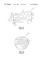
- a magnetic disk drive 10 of the prior artincludes a sealed enclosure 12 , a disk drive motor 14 , a magnetic disk 16 , supported for rotation by a spindle S 1 of motor 14 , an actuator 18 and an arm 20 attached to a spindle S 2 of actuator 18 .
- a suspension 22is coupled at one end to the arm 20 , and at its other end to a read/write head or transducer 24 .
- the transducer 24typically includes an inductive write element with a magnetoresistive read element (shown in FIG. 1 C).
- FIG. 1Cdepicts a magnetic read/write head 30 including a write element 32 and read element 34 .
- the edges of the write element 32 and read element 34also define an air bearing surface ABS in a plane 33 , which flies above the surface of the magnetic disk 16 during operation.
- Read element 34includes a first shield 44 , an intermediate layer 38 which serves as a second shield, and a read sensor 46 located between the first shield 44 and the intermediate layer 38 .
- the read sensor 46has a particular stripe height, SH, and a particular location between the first shield 44 and the second shield 38 , both of which are chosen to attain particular read performance. Control of stripe height is important in controlling device resistance, device output amplitude, device bias point and consequently many related measures of performance.
- MR sensorscan be used with a variety of stripe heights, with a typical SH being smaller than about 2 microns, including less than 1 micron. Further, although the read sensor 46 is shown in FIG.
- the read element 34can take a variety of forms as is known to those skilled in the art, such as unshielded read sensors.
- the design and manufacture of magnetoresistive heads, such as read sensor 46are well known to those skilled in the art.
- Write element 32is typically an inductive write element including the intermediate layer 38 which serves as a first yoke element or pole, and a second yoke element or pole 36 , defining a write gap 40 therebetween.
- the first yoke element 38 and second yoke element 36are configured and arranged relative to each other such that the write gap 40 has a particular throat height, TH.
- a conductive coil 42that is positioned within a dielectric medium 43 . As is well known to those skilled in the art, these elements operate to magnetically write data on a magnetic medium such as a magnetic disk 16 .
- a read/write head 30begins with a wafer 50 , as shown in FIG. 1D, which includes, formed over a substrate, sets of several layers or films of various materials that form an array of read/write heads (not shown), including the elements of the read/write head 30 that are shown in FIG. 1 C.
- the wafer 50is then divided into multiple slider bars 52 such that each slider bar 52 has a first cut surface, or edge, 54 and a second cut surface, or edge, 56 substantially parallel to each other.
- each slider bar 52may include several read/write heads 60 in series along the bar.
- a typical slider barmay include about thirty (30) read/write heads 60 .
- the read/write heads 60can be of different configuration, however, alternatively each of the write/read heads 60 along the slider bar 52 can be of approximately the same configuration.
- the second cut surface 56is formed such that the read/write heads 60 extend through to the second cut surface 56 .
- the read/write heads 60are exposed and therefore available for removing material along the second cut surface 56 in a process termed lapping.
- the read/write heads 60can extend to near the second cut surface 56 , without being initially exposed. In such a case, the read/write heads 60 can become exposed and material can be removed therefrom during the lapping process.
- the goal of lappingis to remove material from the second cut surface 56 , which defines a lapping plane L, to form the ABS (also shown in FIG. 1C) of each of the read/write heads 60 in the plane 33 . More particularly, it is the objective of the lapping process to define the ABS at a precise predetermined distance from the upper edge 64 of the read sensor 46 where the upper edge 64 is defined by wafer processes. In this way, the stripe As height SH of the read sensor 46 (shown in FIG. 1C) is defined substantially orthogonal to the lapping plane L, and the throat height TH is similarly defined substantially orthogonal to the lapping plane L. After lapping, the read/write heads are then each cut from the slider bar to form individual read/write heads.
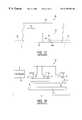
- FIG. 1Fshows a typical lapping machine 70 .
- the slider bar 52is held along the first cut surface 54 by a jig 72 .
- the jig 72is contacted by pistons 74 at various bending points 76 along the length of the jig 72 .
- Pistons 74may be, for example, dual action air cylinders, and are configured to deflect the jig 72 at the bending points 76 by a particular amount.
- a controller 78is used to regulate the operation of the pistons 74 .
- the slider bar 52is further oriented such that the second cut surface 56 lies substantially parallel to an upper surface 80 of a lapping plate 82 .
- an abrasive materialfor example a diamond slurry, is introduced between the second cut surface 56 of the slider bar 52 and the upper surface 80 of the lapping plate 82 .
- the slider bar 52 and the lapping plate 82are moved relative to each other within the plane defined by the second cut surface 56 and the upper surface 80 . This movement, along with the forces acting to press together the upper surface 80 and the second cut surface 56 and with the abrasive material placed therebetween, acts to abrasively lap the second cut surface 56 and thereby the read/write heads 60 .
- FIG. 2Ashows an example of a prior art electrical lapping guide (ELG) 90 , that has been used to provide an indication of stripe height during the lapping process.
- FIG. 2Adepicts a slider bar 52 in cross section at a layer including the read sensor 46 , and associated leads 92 .
- a “switch” 94formed of a resistive element, and a resistive element 96 are electrically connected to the controller 78 through the leads 98 and 100 , respectively.
- a first current I 1passes through the switch 94
- a second current 12passes through the resistive element 96 .
- the measured resistance Rr during the lapping processcan be used to calculate an approximate height of the read sensor 46 during the lapping process. Such a calculated height is shown over time in FIG. 2B by curve 110 .
- the initial height of the switch 94is chosen such that the entire switch is lapped, thereby “breaking” the switch, before the target stripe height SHd of the read sensor is achieved. Because the height Hs of the switch 94 is known relative to the stripe height SH of the read sensor 46 , the remaining stripe height of the read sensor 46 at the time the switch breaks, tsb, can be approximated. Thus, as is shown in FIG.
- the height calculated from Rrcan be calibrated from the approximated read sensor stripe height at the time the switch breaks, tsb.
- the lapping processcontinues until the read sensor 46 stripe height SH is calculated to be approximately the target stripe height SHd at which time, t end , the rate of the lapping process is changed and ultimately the lapping is ended.
- the switch 94 of the ELG 90 in FIG. 2Adoes not have a truly digital response, but rather the resistance Rs increases over time as shown in FIG. 2 B.
- measurement circuitry of a typical lapping systemcannot easily measure a true open resistance.
- endpoint detection with such an ELGis limited by the measurement precision, with undesirable noise incorrectly indicating that the switch 94 is open, sometimes referred to as a false open indication.
- One technique to avoid such a false open indicationis to place a resistive element in parallel with the switch 94 , most typically with a resistance significantly greater than the initial resistance of Rs. The resistance signal detected at the controller will rise to an asymptote equal in value to this parallel resistive element as the switch opens. While a false open indication may be avoided, the resultant endpoint remains imprecise.
- the ELGprovides calibration only around the points when the switch breaks, the ELG is ineffective for use in adjusting the lapping parameters throughout the lapping process.
- the stripe height calculations and calibration of the stripe height calculation using the ELG 90 of FIG. 2Adepends on knowing the relative dimensional and material properties of the ELG switch, resistive element, and leads, as well as the read sensor. Therefore, unknown differences in these properties due to fabrication variations can produce incorrect stripe height calculations and therefore incorrect termination of the lapping process, either too early or too late. Such imprecise determination will likely result in a read sensor 46 having an undesired stripe height and therefore substandard performance characteristics.
- the measured resistance for both switch 94 and resistive element 96 , as well as the read sensor 46will include a leads resistance term and a junction resistance term in addition to the resistance of the switch 94 , resistive element 96 , or read sensor 46 .
- a leads resistance term and a junction resistance termin addition to the resistance of the switch 94 , resistive element 96 , or read sensor 46 .
- Each of these termsis unknown because the dimensions of each feature and the sheet resistance of the respective films will vary across any given wafer, as well as throughout a population of wafers. Also, each of these terms is likely to vary with stripe height during lapping.
- ELG 90 of FIG. 2Ais distributed such that the switch 94 and resistive element 96 are at separate positions between sliders. Due to the unknown curvature of the slider bar, this separation increases the error in assuming that any switch 94 and a neighboring resistive element 96 have precisely known relative stripe heights and therefore results in additional calibration error. Therefore, using ELG 90 is not a satisfactory solution.
- FIG. 3Ashows another currently used electrical lapping guide (ELG) 120 .
- ELGelectrical lapping guide
- Such an ELGincludes a first resistive element 122 located along the lapping plane L and connected to the controller 78 through leads 124 . Also included is a second resistive element 126 electrically connected to the controller 78 through electrical leads 128 , but located distantly from the lapping plane L to act as an untapped reference device.
- a first current I 1 and a second current 12flow through the first resistive element 122 and through the second resistive element 126 , respectively, both of which can be measured and monitored by the controller 78 during the lapping process.
- the dimensions and material properties of the second resistive element 126are chosen such that, at the point in the lapping process where the stripe height of a read sensor 46 will be equal to the target stripe height SHd, a resistance R 1 of the first resistive element 122 is equal to or has some known relationship to a resistance R 2 of the second resistive element 126 .
- the height of the first resistive element 122likewise decreases, thereby changing the resistance R 1 measured across the first resistive element 122 as shown in FIG. 3 B.
- the resistance R 1is detected to be approximately the same as the resistance R 2 , as shown in FIG. 3B at point E, the lapping process is stopped at t end . While only two resistive elements are shown in FIG. 3A, multiple resistive elements can be used. In such ELGs, more than one resistive element can be used as an untapped reference device, providing additional resistance levels with which to determine tend.
- Electrical lapping guidessuch as the ELG 120 of FIG. 3A are also affected by unknown variation in dimensional or material properties across the wafer.
- the prior art approach of placing a single resistive element between slidersis subject to error both due to dimensional and material properties variation across the wafer and is subject to errors due to bar curvature as previously discussed.
- Placing the second resistive element 126 in close physical proximity to the first resistive element 122 and designing second electrical leads 128 which are approximately identical to first electrical leads 124will reduce the cumulative effect of these errors for this structure.
- the dimensional error in defining the stripe height of second resistive element 126translates directly as an error in targeting the stripe height of first resistive element 124 .
- the reference during lapping of the baris not based solely on the position of the upper edge of the respective resistive elements but is also subject to the position of the lower edge of second resistive element 126 .
- Scaling such an ELG to reduce the percentage error in the physical dimensionscan inherently invalidate the junction resistance term between the second electrical leads 128 and the second resistive element 126 .
- an electrical lapping guide and method for controlling the stripe height of a devicethat is more accurate and results in a more precise determination of the device stripe height substantially throughout a process of lapping a read sensor or other device, while limiting cost and complexity. It is desired that such an ELG would provide a substantially continuous signal such that the stripe height may be determined throughout the process of lapping the read sensor. It is further desired that such an ELG utilize the upper edge of the resistive element as a calibration reference to minimize error. Also, it is desired that such an ELG be substantially insensitive to variation in dimensional and materials properties inherent in processing of the wafer.
- the present inventionprovides a more precise determination of device stripe height during a lapping process, and thus results in more accurate stripe height control of a device processed with lapping. This is accomplished by providing an electrical lapping guide whose characteristics can be monitored substantially throughout the process of lapping a device and which is configured such that the effect of fabrication variations on device stripe height determination are minimized.
- a lapping guide for use in fabrication of a device in accordance with the present inventionincludes a substrate, and two resistive elements on the substrate.
- the two resistive elementshave different stripe heights, as defined on the wafer, due to an offset in the relative position of the upper edge of the resistive elements and resulting in different resistances.
- the substratehas an edge defining a lapping plane, and the two resistive elements each have an edge along the lapping plane.
- a process for forming an electrical lapping guideincludes providing a substrate that includes a lapping plane. The process also includes forming, above the substrate, a device that intersects the lapping plane which thereby defines a first edge of the device. The device is formed with an initial height and an associated predetermined desired height. Also, above the substrate a first resistive element that is separate from the device is formed having a first resistance and an initial height that is larger than a difference between the initial and predetermined desired heights of the device. In addition, the first resistive element is formed intersecting the lapping plane, which thereby defines a first edge of the first resistive element.
- a second resistive element that is separate from said deviceis also formed, having a second resistance and an initial height that is larger than a difference between said initial and predetermined desired heights of the device.
- the second resistive elementis also formed intersecting the lapping plane which thereby defines a first edge of the second resistive element.
- the two resistive elementscan have different resistances and can each be electrically connected to a common electrical lead. In this way, the ELG is formed so that the resistances of both resistive elements can be measured throughout a lapping process and used to determine a lapping endpoint using a minimum of external wiring and hardware.
- a method for making a magnetoresistive head in accordance with the present inventionincludes lapping along a lapping plane of a slider bar which includes a magnetoresistive sensor and two resistive elements, the three of which are separate from each other.
- the two resistive elementseach have an edge that is located along the lapping plane, and are each electrically connected to an electrical lead that is located between the two resistive elements.
- the methodadditionally includes passing a first current through one of the resistive elements and passing a second current through the other resistive element to measure different resistances across each resistive element, while the lapping continues. Further, the method includes using the two resistances to determine whether to change a rate of the lapping.
- the various embodiments of the present inventionenable more accurate control of the stripe height of a device by facilitating a more precise determination of the device stripe height throughout a lapping process. Further, this additional accuracy and precision are gained without increasing manufacturing time, cost, or complexity.
- FIG. 1Ais a partial cross-sectional front elevation view of a magnetic disk drive assembly
- FIG. 1Bis a top plan view taken along line 1 B- 1 B of FIG. 1A;
- FIG. 1Cis a cross-sectional side view of a read-write head incorporating a shielded magnetoresistive read sensor
- FIG. 1Dis a plan view of a wafer including multiple slider bars that incorporate multiple read-write heads
- FIG. 1Eis a partial plan view of an individual one of the slider bars shown in FIG. 1D;
- FIG. 1Fis a schematic diagram of a lapping machine in which a slider bar is positioned
- FIG. 2Ais a partial cross-sectional plan view of a slider bar that incorporates a prior art electrical lapping guide and a read sensor;
- FIG. 2Bis a graphical depiction of various physical characteristics of the electrical lapping guide and read sensor of FIG. 2A over time during a lapping process;
- FIG. 3Ais a partial cross-sectional plan view of a slider bar that incorporates another prior art electrical lapping guide and read sensor;
- FIG. 3Bis a graphical depiction of resistances in the electrical lapping guide over time during a lapping process
- FIG. 4Bis a partial cross-sectional plan view of the electrical lapping guide schematically depicted in FIG. 4A, according to an embodiment of the present invention
- FIG. 4Cis a partial cross-sectional elevation view of the electrical lapping guide depicted in FIG. 4B, according to an embodiment of the present invention.
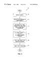
- FIG. 5is a flow chart of a process for forming an electrical lapping guide, according to another embodiment of the present invention.
- FIG. 6is a flow chart of a method for controlling a read sensor stripe height during a lapping process, according to yet another embodiment of the present invention.
- FIG. 7is a schematic of current flowing through the electrical lapping guide shown in FIG. 4, according to an embodiment of the present invention.
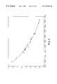
- FIG. 8is a graph of read sensor stripe height versus a resistance ratio of the electrical lapping guide during a lapping process, according to the yet another embodiment of the present invention.
- FIG. 10is a partial cross-sectional plan view schematic of a slider bar that incorporates a read sensor and an electrical lapping guide according to another embodiment of the present invention.
- FIGS. 1A-F, 2 A-B, and 3 A-Bwere discussed with reference to the prior art.
- FIGS. 4A-10 and related discussion belowillustrate apparatuses and methods for providing an electrical lapping guide (ELG) that facilitates changing the rate of lapping a slider bar as a stripe height SH of a read sensor approaches a target stripe height SHd.
- ELGelectrical lapping guide
- the ELGincludes two resistive elements that continuously provide changing resistance signals from before and up to the time the target stripe height is reached.
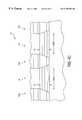
- FIG. 4Ais a partial cross-sectional view of an electrical lapping guide (ELG) 140 according to an embodiment of the present invention, located near a device, specifically a read sensor 46 with leads 92 , on a slider bar 142 .
- Read sensor 46may be a magnetoresistive read sensor, and is defined by a height, or stripe height, SH, and a trackwidth, TWS.
- other read sensorsmay also be located on the slider bar near the ELG 140 .
- Such proximity to the read sensors 46minimizes fabrication (i.e., dimensional and material property) variations between the read sensors 46 and the ELG 140 .
- other ELGs 140may be located along the slider bar 142 near other read sensors 46 (not shown).
- the ELG 140includes a first resistive element 144 , and a second resistive element 146 separated from the first resistive element 144 by a common lead 148 , which is in electrical contact with both resistive elements.
- the first resistive element 144 and the second resistive element 146also are electrically connected to a first electrical lead 150 and a second electrical lead 152 , respectively.
- the leads 148 , 150 , and 152are each electrically connected to a controller (not shown) through which currents can be applied to the first resistive element 144 and the second resistive element 146 , and through which resistances of the first resistive element 144 and of the second resistive element 146 can be measured.
- first resistive element 144 and the second resistive element 146are each defined by a particular height, H 1 and H 2 , respectively, and by a particular width, or trackwidth, TWR 1 and TWR 2 , respectively. It should be noted that because of the proximity of the first resistive element and second resistive element, during the lapping process, the two are lapped at essentially the same rate, and thus the relationship between H 1 and H 2 remains substantially the same. Although TWR 1 and TWR 2 are shown as approximately equal, and are so preferred, in some embodiments of the present invention they may be different. In either case, TWR 1 and TWR 2 are preferably substantially larger than TWS.
- TWR 1 and TWR 2The larger the size of TWR 1 and TWR 2 , the less impact there is of other ELG components on endpoint determination, as is further discussed below. In addition, larger TWR 1 and TWR 2 minimize the impact on endpoint determination of trackwidth dimensional errors during the fabrication of the ELG resistive elements. For example, with appropriate dimensions, typical dimensional errors can result in about a 1% error, rather than a 10% error that can otherwise be experienced. For example, to obtain such benefits TWS can be about 1 micron or less, while TWR 1 and TWR 2 can be in the range of about 1 micron to about 100 microns, and preferably about 25 microns. The selection of particular TWR 1 and TWR 2 values is further influenced by the area available on a slider bar for the ELG versus the area occupied by read/write heads.
- the read sensor 46is also defined by a height, or stripe height, SH.
- SHheight, or stripe height
- the read sensorhas a height SHw, while the first and second resistive elements have heights H 1 w and H 2 w, respectively.
- the sensor and first and second resistive elementshave the respective pre-lapped initial heights SHi, H 1 i, and H 2 i.
- the initial heightwill be substantially equal to the wafer-level height.
- the slicing operationdoes not cut through a resistive element, there will be no change in resistance of that resistive element until a lapping plane L reaches the lower edge of that resistive element.
- the slider bar 142is lapped along the lapping plane L, over time reducing SH, along with H 1 and H 2 , from the initial pre-lapped SHi, H 1 i, and H 2 i until SH is equal to a desired, or target stripe height SHd.
- SHdesired, or target stripe height
- initial lower edges of the resistive elementsare below a final plane 143 which includes the read sensor ABS, and upper edges of the resistive elements are above the final plane 143 .
- This criteriacan be satisfied regardless of the position of the resistive element lower edges relative to the lower edge of the read sensor, and whether or not the initial lower edges of the resistive elements extend to the initial lapping plane. However, if the resistive elements do not extend to the initial lapping plane, the resistances will begin to change once the lapping plane L reaches the lower edges of the resistive elements.
- the resistive elementsprovide a changing signal throughout the lapping of the slider bar, from the initial lapping plane to the plane 143 which includes the read sensor ABS.
- the lower edges of the resistive elementsextend to the initial lapping plane, thereby allowing the resistive elements to be lapped from the beginning of the lapping process.
- the distance between the wafer level lower edges of the resistive elements and the plane 143be greater than or equal to the distance between the plane 143 and the wafer level read sensor lower surface.
- the wafer level lower surfaces of the resistive elementscan alternatively be as close as or closer than the wafer level lower surface of the read sensor is to the plane 143 .
- the upper edges of the resistive elementsextend above the plane 143 , which includes the read sensor ABS.
- the distances between the initial lapping plane and the upper edges of the first and second resistive elementsare greater than the distance between the initial lapping plane and the plane 143 .
- an SHw of about 16 micronscan be lapped to an SHd of about 1 micron.
- the H 1 wcould be about 19 microns
- H 2 wcould be about 17 microns.
- H 1 w and H 2 wbe at least about 15 microns larger than the target stripe height SHd.
- a goal during the lapping processis to change the rate of lapping as SH approaches the target stripe height SHd, including stopping the lapping at an endpoint when SH is approximately equal to SHd.
- the lapping plane Lis coincident with plane 143 and incorporates the air bearing surface ABS.
- FIG. 4Bshows another partial cross-sectional view of the ELG 140 of the present invention.
- H 1is different from H 2
- TWR 1is approximately equal to TWR 2 .
- Additional electrical connection elements(not shown) that facilitate electrical connection of the leads 148 a , 150 a , and 152 a to a controller (not shown) can also be included.
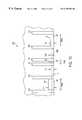
- FIG. 4Cshows a partial schematic of the ELG 140 according to one embodiment of the invention, viewing the air bearing surface.
- the materials of the first and second resistive elementsare the same. Also, preferably the first and second elements are formed of the same materials and at the same time as the formation of the read sensor 46 , as this results in the minimum process complexity. Thus, the first and second resistive elements 144 , 146 are formed of the same multiple layers, or films, in the same order and with the same method as used for the formation of a multi-layer read sensor 46 and thereby their respective depths D 1 and D 2 are substantially the same. The materials and order of such layers depend upon the desired characteristics of the finished read sensor 46 .
- the trackwidthtypically will be defined by the longitudinal bias and thin film leads layers.
- first and second resistive elements 144 , 146can be defined in a film which differs from read sensor 46 , but first and second resistive elements 144 , 146 must be etched to define the trackwidth of the first resistive element simultaneously with the trackwidth of the second resistive element, and to define the stripe height of the first and second resistive element simultaneously with the stripe height of the read sensor 46 . Subsequently, the read sensor and resistive elements are covered with dielectric material.
- the dielectric materialcan be etched in subsequent processes, for example using masks and patterned photoresist, to form read sensor lead vias (not shown) and ELG lead vias 160 of FIG. 4 B.
- Successive layers of conductive materialscan be deposited and patterned to provide electrical continuity from the leads via to the desired location of the probe pads, as the read sensor connections are defined (not shown in FIG. 4 B).
- These layersmay be defined by many techniques including, but not limited to, vacuum deposition and liftoff or electroplating with a resist mask using appropriate conductive materials which may include gold and copper.
- leads 92 , 148 , 150 , and 152are understood to be schematic representations of these combined structures.
- the leads 148 , 150 , 152are preferably formed of the same materials as each other, and more preferably formed of the same materials and at the same time as the read sensor leads 92 .
- a process 170 for forming an ELG according to another embodiment of the present inventioncan be more clearly understood from the flow chart shown in FIG. 5 .
- the process 170includes preparing a substrate in operation 172 , which includes providing materials which form the first shield and first read gap, upon which read sensor materials and materials forming first and second resistive elements are deposited in operation 174 .
- the same materialscan be deposited for both the sensor and resistive elements, with layers of different materials being successively deposited when a multilayer read sensor is formed.
- the resistive element trackwidths TWR 1 and TWR 2are defined as approximately equal to each other, and the read sensor trackwidth TWS is defined.
- TWR 1 and TWR 2are significantly larger than TWS.
- the resistive element heights H 1 and H 2are also defined to be different from each other in operation 178 .
- This differencepreferably includes an offset in the locations of the upper edges of the first and second resistive elements and may include an offset in the positions of the lower edges of the first and second resistive elements provided that H 1 and H 2 are defined to be greater than the difference between the initial and target sensor stripe heights, SHw and SHd, to ensure that signals which vary with stripe height can be monitored from both resistive elements throughout the lapping process. Because a continuous signal is available substantially throughout, with appropriate lapping equipment lapping parameters can be adjusted continuously throughout the process as needed to appropriately lap the slider bar.
- such capabilityenables the lapping to be completed at substantially the same time across the entirety of the slider bar, regardless of varying material properties or curvature across the slider bar. Further, the continuous signal substantially throughout enables such adjustments to be made precisely and early in the lapping process. Also advantageously, because the ELG resistive elements are not entirely lapped away, the target endpoint can be easily changed, within certain limits dependent upon H 1 and H 2 . Thus, the same ELG design can be used for the fabrication of a variety of sensors having different target stripe heights SHd.
- sensor leads electrically connected to the read sensorare formed.
- a common lead electrically connected to and between the first and second resistive elementsis formed, along with one additional lead per resistive element.
- the common leadcan be formed such that it is the only structure or material that lies between and within the same plane as the two resistive elements of the ELG, such as in a contiguous junction hard biased read sensor design.
- the first and second resistive elementscan be physically contiguous, with the leads structures formed in a plane different than the two resistive elements (sometimes referred to as an overlay structure), such as in a typical exchange biased device or a non-contiguous junction hard biased device.
- the common leadcould be formed having a surface contact with the two resistive elements in a region where the two are contiguous.
- these leadscan be formed in operation 180 from a single material or with multiple layers of different materials.
- the ELG resistive elementscan be formed of the same materials with the same layering structure as the read sensor, thereby reducing fabrication complexity.
- the ELG trackwidth, stripe height, and leads structurescan be defined during the process steps which define the read sensor trackwidth, stripe height, and leads structures.
- the material deposition, definition of stripe height and trackwidth, and formation of electrical leadsare performed using known methods such as chemical vapor deposition, physical vapor deposition, ion beam deposition, spin coating, reactive ion etching,-plasma etching, plating, and other methods known to those skilled in the art.
- the process 170also includes additional processing to complete the wafer in operation 182 .
- Such processingcan include the addition of a shield above the read sensor, as well as the inductive write element conductive coil and second yoke element (refer to FIG. 1 C). Additionally, portions of the read sensor and ELG leads typically will be defined simultaneously with some of the inductive write element processes, in an embodiment having reduced complexity.
- the process 170can be performed in the order discussed above, the operations can alternatively be performed in other orders.
- FIG. 6depicts a method 190 for using an electrical lapping guide, ELG, according to an embodiment of the present invention, to control a read sensor stripe height during lapping.
- Method 190includes initiating the lapping of a cut edge of a slider bar that includes an ELG according to an embodiment of the present invention, in operation 192 . While the lapping initiated in operation 192 continues, in operation 194 currents I 1 and I 2 are applied to the first and second resistive elements of the ELG. This is further illustrated in FIG. 7 with respect to first resistive element 144 and second resistive element 146 . Referring again to FIG. 6, in operation 196 , and while the lapping continues, the resistances R 1 and R 2 across the first and second resistive elements, respectively, are measured.
- a controllerdetermines whether to change the rate of lapping, including whether to stop the lapping in operation 198 .
- a controllerspecifically configured for this method, determines whether to change the rate of lapping, including whether to stop the lapping in operation 198 .
- operations 194 - 198can be performed after lapping has been initiated, but before all lapping is completed, operations 194 - 196 can be performed after lapping is completed.
- the determinations in operation 198are made when R 1 and R 2 are used to determine that the current stripe height of the read sensor is nearing or approximately equal to the target read sensor stripe height SHd. More specifically, for the ELG according to an embodiment of the present invention, when the material properties of the first and second resistive elements are approximately identical, the first and second resistive element trackwidths TWR 1 and TWR 2 are approximately equal, and the first and second resistive element initial (pre-lapping) heights H 1 i and H 2 i are different, then the ratio of the resistances R 1 and R 2 measured across the first and second resistive elements, respectively, is inversely proportional to the ratio of H 1 and H 2 at any given time during the lapping process.
- the difference between H 1 and H 2can be known for all times that H 1 and H 2 have positive values.
- the read sensor stripe heightcan be determined at any time during the lapping process. This relationship between the ratio of resistances and read sensor stripe height SH is illustrated in FIG. 8 . As can be seen by the curve of FIG. 8, as SH decreases (i.e., is lapped away), the resistive element resistance ratio increases.
- the method of determining whether to change the rate of or to stop the lappingcan be further understood from the following equations.
- a combined resistance throughout the particular path of the introduced current I 1 or I 2is actually measured.
- the resistance of a first ELG element, Ree 1which is formed by the first resistive element, the common lead and the first electrical lead, and a second ELG element, Ree 2 , formed by the second resistive element, the common lead and the second electrical lead, are given by:
- Ree 1R 1 +Rlc+Rl 1 +Rjunct 1 ,
- Rlcis the resistance due to the common lead
- Rl 1 and Rl 2are the resistances due to the first and second electrical leads, respectively
- Rjunct 1 and Rjunct 2are the resistances due to the junctions between the corresponding resistive elements and the leads.
- the leads and junctionsare formed such that RI 1 , Rl 2 , Rlc, Rjunct 1 , and Rjunct 2 are negligible relative to R 1 and R 2 .
- the leads resistanceis minimized by using low resistivity materials.
- the leads resistancecan also be minimized by minimizing the distance over which the leads are formed only from the thin films utilized in read sensor fabrication by designing the via for contact between the thin films leads and the thicker conductors used in the write head process, in close proximity to the resistive elements.
- defining the trackwidths of the resistive elements to be substantially larger than the trackwidth of the sensorcan minimize the relative impact of the leads and junction resistance because R 1 and R 2 are directly proportional to TWR 1 and TWR 2 , respectively.
- TWR 1 and TWR 2 of the resistive elements in the range of about 10 microns to about 100 micronswill increase the resistances of the ELG resistive elements by approximately one to two orders of magnitude with respect to the read sensor, resulting in R 1 and R 2 being the predominant terms in the ELG resistance.
- R 1 and R 2being the predominant terms in the ELG resistance.
- Ree 1 and Ree 2are reduced to R 1 and R 2 , and thereby the ratio Ree 2 /Ree 1 is reduced to the ratio R 2 /R 1 .
- p 1 and p 2are the resistivities and D 1 and D 2 are the depths (refer to FIG. 4C) of the first and second resistive elements, respectively.
- the value of the ratio p/Dcould be estimated by an untapped reference structure formed of the same material or materials and with the same depth as the first and second resistive elements.
- H 2x /((R 2 /R 1 ) ⁇ 1).
- Rjunct 1 and Rjunct 2are negligible with respect to R 1 and R 2 . Since Rjunct 1 and Rjunct 2 arise from the approximate edge to edge contact of a contiguous junction structure, Rjunct 1 and Rjunct 2 will vary in inverse proportion to stripe height during lapping. Similarly, the resistance terms Rl 1 , Rl 2 , and Rlc can be further separated into a fixed term, representing the leads structure above the first and second resistive elements, and a variable term representing the portions of the leads adjacent to the first and second resistive elements which also vary with stripe height during lapping.
- Rl 1can be expressed as Rl 1 f+Rl 1 v
- Fl 2can be expressed as Rl 2 f+Rl 2 v
- Rlccan be expressed as Rlcf+Rlcv
- Rl 1 f, Rl 2 f, and Rlcfrepresent the fixed component of Rl 1 , Rl 2 , and Rlc, respectively
- Rl 1 v, Rl 2 v, and Rlcvrepresent the component which varies in inverse proportion to stripe height of RI 1 , Rl 2 , and Rlc, respectively.
- the fixed term of the leads resistancebe designed to be approximately identical in some lapping control schemes and there is substantially no disadvantage to such a relationship in any control scheme.
- H 2x /(((R 2 ⁇ F )/(R 1 ⁇ F )) ⁇ 1)
- This method of the current inventionis more accurate than in other systems of the prior art because the symmetry of the ELG lead design, proximity of the resistive elements to each other, shared common lead, and approximately equal trackwidth cause the calculation of read sensor stripe height to be minimally affected by most potential errors that would be caused by possible fabrication variations.
- the lapping endpointis determined from only the differences in height between the resistive elements and the read sensor, obviating the need to consider terms that are difficult or impossible to determine or for which it is difficult or impossible to compensate.
- This difference in heightis defined by the difference between upper edges 151 and 153 of the ELG resistive elements as shown in FIG. 4 A.
- resistive elementswere defined at the same time as the sensor, the relationship between the resistive element upper edges 151 , 153 and an upper edge 93 of the sensor is known and can be used as a reliable reference. Further, using R 2 /R 1 produces a more linear response which facilitates signal monitoring and determination of the endpoint during lapping.
- a method 210 for controlling stripe height using an ELG of the present inventionis shown by the process diagram of FIG. 9 .
- operation 214involves the application of a known voltage source Vin across the first and second electrical leads 150 , 152 .
- a voltage Voutis measured at the common lead 148 located between the first and second resistive elements. In this way, the first and second resistive elements, combined with the additional resistance terms which are inversely proportional to stripe height, are used as a voltage divider.
- lappingcan be controlled by measuring Vout and adjusting the lapping rate to achieve a balanced output voltage. Further, with the known voltage Vin, and measured voltage Vout, it can be determined in operation 218 whether to adjust the rate of lapping, including whether to stop lapping.
- operations 214 - 218can be performed after lapping has been initiated, but before all lapping is completed, operations 214 - 216 can be performed after lapping is completed.
- VoutR2 R1 + R2 ⁇ Vin
- VoutSH + x + y 2 ⁇ SH + x + 2 ⁇ y ⁇ Vin
- H2x ⁇ ( ( Vout / Vin ) - 1 ) 1 - ( 2 ⁇ Vout / Vin )
- the same resistances R 1 and R 2may also be used in conjunction with other methods.
- the difference between total resistance Ree 2 and Ree 1can be used, with appropriate manipulation, to determine the sensor stripe height SH throughout a lapping process.
- using this methodsubstantially obviates a need for negligible leads resistance, because they can be designed to cancel out.
- this methodresults in an expression for the difference in resistance containing a second order term for stripe height, it may be more practical to utilize a control algorithm based on calculating an expected resistance difference at the desired read sensor stripe height.
- This methodmay result in reduced precision because it must rely on using resistance measurements taken before any portion of the ELG is modified by processing of the slider bar and must assume that the initial heights H 1 w and H 2 w of R 1 and R 2 , as defined by wafer processes, are known. This may result in a calibration error of 1 to 5% depending on the initial height of the first and second resistive elements and the tolerance to which the initial heights are controlled.
- These initial resistance measurements Ree 1 w and Ree 2 wmay be used to determine a coefficient, K, representing the variation of R 1 , R 2 , Rl 1 v, Rl 2 v, Rlcv, Rjunct 1 , and Rjunct 2 with stripe height in terms of the difference Ree 2 w ⁇ Ree 1 w, the designed offset in height x, and the initial height H 2 w:
- Ree 2 w ⁇ Ree 1 wK ((1/H 2 w) ⁇ (1/(H 2 w+ x )))
- the difference in resistance as a function of the height of the second resistive elementmay be expressed as:
- Ree 2 ⁇ Ree 1Kx /(H 2 (H 2 + x ))
- Ree 2 ⁇ Ree 1Kx /(((SH+ y )(SH+ x+y ))
- a target value for this resistance differencemay be determined based on the desired final read sensor stripe height, SH.
- H 2K /(Ree 2 ⁇ (Rl 2 f+Rlcf))
- H 2( K H 2 w)/( K +(Ree 3 ⁇ Ree 2 w)H 2 w)
- K( Ree2w - Ree1w ) ⁇ ( H2w ⁇ ( H2w + ( H1w - H2w ) ) ) ( H1w - H2w )
- an ELG 220can include the first resistive element 144 and second resistive element 146 disposed on opposite sides of the read sensor 46 as shown in FIG. 10 . Because the two resistive elements are not disposed adjacent to each other, there is no common lead as was shown in FIG. 4 A. Rather, the first resistive element is connected to a pair of leads 222 while the second resistive element is connected to a different pair of leads 224 . As with the device of FIG.
- the resistances R 1 and R 2 of the two resistive elementscan be monitored and mathematically manipulated to determine the changing read sensor stripe height and to modify the lapping rate accordingly. While this physical arrangement may result in a slight compromise to the assumption that the dimensions and material properties of the two resistive elements are identical, it advantageously increases the validity of the assumption that the offset in stripe height between the ELG resistive elements and the read sensor is controlled by the designed offset. Thus, the impact of any curvature in the slider bar is substantially eliminated, at least at the point of control.
- Another embodimentcould utilize each lead 92 as a lead shared with the respective adjacent resistive element. In such an embodiment, having each of the two resistive elements formed of a material different from that of the read sensor may be beneficial.
- first resistive element and second resistive elementformed of the same material as the read sensor, and having the same trackwidths but different heights
- other combinations of materials, trackwidths and heights that result in different resistances of the first resistive element and second resistive elementcould be used with appropriate modification of the above described method.
- the first and second resistive elementscan be formed of different materials and be patterned at the same time as the read sensor.
- the various embodiments of the present invention described abovecan be used in conjunction with a read sensor in the form of an AMR, GMR, or spin valve read sensor.
- the present inventioncan be utilized to more precisely control the stripe height of any device similarly situated relative to the electrical lapping guide of the present invention.
Landscapes
- Engineering & Computer Science (AREA)
- Manufacturing & Machinery (AREA)
- Mechanical Engineering (AREA)
- Magnetic Heads (AREA)
- Hall/Mr Elements (AREA)
Abstract
Description


Claims (30)
Priority Applications (2)
| Application Number | Priority Date | Filing Date | Title |
|---|---|---|---|
| US09/321,486US6193584B1 (en) | 1999-05-27 | 1999-05-27 | Apparatus and method of device stripe height control |
| JP2000159237AJP2001014617A (en) | 1999-05-27 | 2000-05-29 | Lapping guide, method for forming electric lapping guide, manufacture of magnetoresistance head and electric lapping guide |
Applications Claiming Priority (1)
| Application Number | Priority Date | Filing Date | Title |
|---|---|---|---|
| US09/321,486US6193584B1 (en) | 1999-05-27 | 1999-05-27 | Apparatus and method of device stripe height control |
Publications (1)
| Publication Number | Publication Date |
|---|---|
| US6193584B1true US6193584B1 (en) | 2001-02-27 |
Family
ID=23250795
Family Applications (1)
| Application Number | Title | Priority Date | Filing Date |
|---|---|---|---|
| US09/321,486Expired - LifetimeUS6193584B1 (en) | 1999-05-27 | 1999-05-27 | Apparatus and method of device stripe height control |
Country Status (2)
| Country | Link |
|---|---|
| US (1) | US6193584B1 (en) |
| JP (1) | JP2001014617A (en) |
Cited By (182)
| Publication number | Priority date | Publication date | Assignee | Title |
|---|---|---|---|---|
| WO2001091115A3 (en)* | 2000-05-25 | 2002-05-30 | Seagate Technology Llc | Improved lapping sensor for recording heads |
| US20020135951A1 (en)* | 2001-01-19 | 2002-09-26 | Tdk Corporation | Thin-film magnetic head and method of manufacturing same, and method of forming a patterned thin film for a thin-film magnetic head |
| US20020173227A1 (en)* | 2001-03-16 | 2002-11-21 | Lam Chuck Fai | Embedded lapping guide |
| US20030026046A1 (en)* | 2001-07-31 | 2003-02-06 | Hitachi, Ltd. | Magnetic head and method of manufacturing the same |
| US6568992B1 (en)* | 2000-04-14 | 2003-05-27 | Seagate Technology, Llc. | Method for controlling MRE stripe height |
| US20030220050A1 (en)* | 2002-05-24 | 2003-11-27 | Bunch Richard D. | Removable lapping guide for magnetic recording haed and method of use |
| US20040009739A1 (en)* | 2002-07-12 | 2004-01-15 | Li-Yan Zhu | Dual-purpose lapping guide for the production of magneto-resistive heads |
| US6684171B2 (en) | 2002-04-22 | 2004-01-27 | International Business Machines Corporation | In-situ stripe height calibration of magneto resistive sensors |
| US20040075942A1 (en)* | 2002-05-30 | 2004-04-22 | Bajorek Christopher H. | Lapping a head while powered up to eliminate expansion of the head due to heating |
| US6728067B2 (en)* | 2001-07-30 | 2004-04-27 | Hitachi Global Storage Technologies Netherlands B.V. | Slider having integrated lapping guides |
| US20040097173A1 (en)* | 2002-11-19 | 2004-05-20 | International Business Machines Corporation | Onboard multiphase electronic lapping guide design for MR heads |
| US20040180608A1 (en)* | 2003-02-28 | 2004-09-16 | International Business Machines | Ion bombardment of electrical lapping guides to decrease noise during lapping process |
| US20050002124A1 (en)* | 2002-08-19 | 2005-01-06 | Bunch Richard D. | Storage device slider with sacrificial lapping extension |
| US6859678B1 (en)* | 1999-06-21 | 2005-02-22 | Tdk Corporation | Method and apparatus for manufacturing magnetoresistive element, software and system for controlling manufacturing of magnetoresistive element, software for estimating resistance value of magnetoresistive element, and computer system |
| US20050070206A1 (en)* | 2003-09-29 | 2005-03-31 | Prakash Kasiraj | Slider fabrication system for sliders with integrated electrical lapping guides |
| US6884148B1 (en)* | 2004-05-26 | 2005-04-26 | Headway Technologies, Inc. | Independently controlled read and write head stripe height parameters in slider back end process |
| US20050128638A1 (en)* | 2003-12-15 | 2005-06-16 | International Business Machines | Patterning of integrated closure for implementing pads connected to lapping elements |
| US20050237673A1 (en)* | 2004-04-27 | 2005-10-27 | Tdk Corporation | Method for grinding a bar of thin film magnetic elements utilizing a plurality of resistive films |
| US20060028770A1 (en)* | 2004-08-03 | 2006-02-09 | Hitachi Global Storage Technologies Netherlands B.V. | Magnetic head with electro lapping guide and manufacturing method |
| EP1626392A1 (en)* | 2004-08-13 | 2006-02-15 | Quantum Corporation | Method of manufacturing magnetic heads with reference and monitoring lapping guides |
| US20060068685A1 (en)* | 2004-09-30 | 2006-03-30 | Hitachi Global Storage Technologies Netherlands B.V. | In-line contiguous resistive lapping guide for magnetic sensors |
| US20060103983A1 (en)* | 2004-11-17 | 2006-05-18 | Fontana Robert E Jr | Distributed shunt structure for lapping of current perpendicular plane (CPP) heads |
| US20060139802A1 (en)* | 2004-12-28 | 2006-06-29 | Headway Technologies, Inc. | Method of manufacturing magnetic head, and magnetic head sub-structure |
| US20060168798A1 (en)* | 2005-01-31 | 2006-08-03 | Kabushiki Kaisha Toshiba | Method of lapping row bar in which perpendicular magnetic heads are formed and lapping machine |
| US20060262439A1 (en)* | 2005-05-19 | 2006-11-23 | Quantum Corporation | Magnetic recording heads with bearing surface protections and methods of manufacture |
| US7170721B2 (en) | 2002-06-25 | 2007-01-30 | Quantum Corporation | Method of producing flux guides in magnetic recording heads |
| US20070230063A1 (en)* | 2006-04-03 | 2007-10-04 | Seagle David J | Method for merging sensor field-mill and electronic lapping guide material placement for a partial mill process and sensor formed according to the method |
| US20080022510A1 (en)* | 2006-07-21 | 2008-01-31 | Hitachi Global Storage Technologies Netherlands B.V. | Method of manufacturing magnetic head slider |
| US20080072418A1 (en)* | 2006-09-01 | 2008-03-27 | Hitachi Global Storage Technologies Netherlands B.V. | Method for manufacturing a magnetic head slider |
| US20090128954A1 (en)* | 2007-11-16 | 2009-05-21 | Sun Microsystems, Inc. | Electrical lapping guide for magnetic tape heads |
| US7551406B1 (en) | 2005-07-01 | 2009-06-23 | Western Digital (Fremont), Llc | Dual electrical lapping guides with common bonding pad |
| US7554767B1 (en)* | 2005-07-01 | 2009-06-30 | Western Digital (Fremont), Llc | Electrical lapping guide disposed laterally relative to a shield pedestal |
| US20090211081A1 (en)* | 2008-02-25 | 2009-08-27 | Boone Jr Thomas D | Controlled lapping for an abs damascene process |
| US20100162556A1 (en)* | 2008-12-30 | 2010-07-01 | Unal Murat Guruz | Electrical lapping guide for improving magnetic core width in a magnetic recording head |
| US8018678B1 (en) | 2008-11-26 | 2011-09-13 | Western Digital (Fremont), Llc | Method for simultaneous electronic lapping guide (ELG) and perpendicular magnetic recording (PMR) pole formation |
| US8151441B1 (en) | 2008-03-27 | 2012-04-10 | Western Digital (Fremont), Llc | Method for providing and utilizing an electronic lapping guide in a magnetic recording transducer |
| US8165709B1 (en) | 2009-02-26 | 2012-04-24 | Western Digital (Fremont), Llc | Four pad self-calibrating electronic lapping guide |
| US8291743B1 (en) | 2009-05-27 | 2012-10-23 | Western Digital (Fremont), Llc | Method and system for calibrating an electronic lapping guide for a beveled pole in a magnetic recording transducer |
| US8307539B1 (en) | 2009-09-30 | 2012-11-13 | Western Digital (Fremont), Llc | Method for modeling devices in a wafer |
| US20120292537A1 (en)* | 2011-05-20 | 2012-11-22 | Nuflare Technology, Inc. | Charged particle beam writing apparatus and method of same |
| US8343364B1 (en) | 2010-06-08 | 2013-01-01 | Western Digital (Fremont), Llc | Double hard-mask mill back method of fabricating a near field transducer for energy assisted magnetic recording |
| US8375565B2 (en) | 2010-05-28 | 2013-02-19 | Western Digital (Fremont), Llc | Method for providing an electronic lapping guide corresponding to a near-field transducer of an energy assisted magnetic recording transducer |
| US8443510B1 (en) | 2009-05-28 | 2013-05-21 | Western Digital (Fremont), Llc | Method for utilizing an electronic lapping guide for a beveled pole in a magnetic recording transducer |
| US8749790B1 (en) | 2011-12-08 | 2014-06-10 | Western Digital (Fremont), Llc | Structure and method to measure waveguide power absorption by surface plasmon element |
| US8758083B1 (en) | 2010-09-13 | 2014-06-24 | Western Digital (Fremont), Llc | Method and system for adjusting lapping of a transducer using a disk windage |
| US8830628B1 (en) | 2009-02-23 | 2014-09-09 | Western Digital (Fremont), Llc | Method and system for providing a perpendicular magnetic recording head |
| US8879207B1 (en) | 2011-12-20 | 2014-11-04 | Western Digital (Fremont), Llc | Method for providing a side shield for a magnetic recording transducer using an air bridge |
| US8883017B1 (en) | 2013-03-12 | 2014-11-11 | Western Digital (Fremont), Llc | Method and system for providing a read transducer having seamless interfaces |
| US8917581B1 (en) | 2013-12-18 | 2014-12-23 | Western Digital Technologies, Inc. | Self-anneal process for a near field transducer and chimney in a hard disk drive assembly |
| US8923102B1 (en) | 2013-07-16 | 2014-12-30 | Western Digital (Fremont), Llc | Optical grating coupling for interferometric waveguides in heat assisted magnetic recording heads |
| US8947985B1 (en) | 2013-07-16 | 2015-02-03 | Western Digital (Fremont), Llc | Heat assisted magnetic recording transducers having a recessed pole |
| US8953422B1 (en) | 2014-06-10 | 2015-02-10 | Western Digital (Fremont), Llc | Near field transducer using dielectric waveguide core with fine ridge feature |
| US8958272B1 (en) | 2014-06-10 | 2015-02-17 | Western Digital (Fremont), Llc | Interfering near field transducer for energy assisted magnetic recording |
| US8971160B1 (en) | 2013-12-19 | 2015-03-03 | Western Digital (Fremont), Llc | Near field transducer with high refractive index pin for heat assisted magnetic recording |
| US8970988B1 (en) | 2013-12-31 | 2015-03-03 | Western Digital (Fremont), Llc | Electric gaps and method for making electric gaps for multiple sensor arrays |
| US8976635B1 (en) | 2014-06-10 | 2015-03-10 | Western Digital (Fremont), Llc | Near field transducer driven by a transverse electric waveguide for energy assisted magnetic recording |
| US8980109B1 (en) | 2012-12-11 | 2015-03-17 | Western Digital (Fremont), Llc | Method for providing a magnetic recording transducer using a combined main pole and side shield CMP for a wraparound shield scheme |
| US8982508B1 (en) | 2011-10-31 | 2015-03-17 | Western Digital (Fremont), Llc | Method for providing a side shield for a magnetic recording transducer |
| US8988812B1 (en) | 2013-11-27 | 2015-03-24 | Western Digital (Fremont), Llc | Multi-sensor array configuration for a two-dimensional magnetic recording (TDMR) operation |
| US8984740B1 (en) | 2012-11-30 | 2015-03-24 | Western Digital (Fremont), Llc | Process for providing a magnetic recording transducer having a smooth magnetic seed layer |
| US8988825B1 (en) | 2014-02-28 | 2015-03-24 | Western Digital (Fremont, LLC | Method for fabricating a magnetic writer having half-side shields |
| US8993217B1 (en) | 2013-04-04 | 2015-03-31 | Western Digital (Fremont), Llc | Double exposure technique for high resolution disk imaging |
| US8995087B1 (en) | 2006-11-29 | 2015-03-31 | Western Digital (Fremont), Llc | Perpendicular magnetic recording write head having a wrap around shield |
| US9001467B1 (en) | 2014-03-05 | 2015-04-07 | Western Digital (Fremont), Llc | Method for fabricating side shields in a magnetic writer |
| US9001628B1 (en) | 2013-12-16 | 2015-04-07 | Western Digital (Fremont), Llc | Assistant waveguides for evaluating main waveguide coupling efficiency and diode laser alignment tolerances for hard disk |
| US8997832B1 (en) | 2010-11-23 | 2015-04-07 | Western Digital (Fremont), Llc | Method of fabricating micrometer scale components |
| US9007879B1 (en) | 2014-06-10 | 2015-04-14 | Western Digital (Fremont), Llc | Interfering near field transducer having a wide metal bar feature for energy assisted magnetic recording |
| US9007725B1 (en) | 2014-10-07 | 2015-04-14 | Western Digital (Fremont), Llc | Sensor with positive coupling between dual ferromagnetic free layer laminates |
| US9007719B1 (en) | 2013-10-23 | 2015-04-14 | Western Digital (Fremont), Llc | Systems and methods for using double mask techniques to achieve very small features |
| US9013836B1 (en) | 2013-04-02 | 2015-04-21 | Western Digital (Fremont), Llc | Method and system for providing an antiferromagnetically coupled return pole |
| US9042208B1 (en) | 2013-03-11 | 2015-05-26 | Western Digital Technologies, Inc. | Disk drive measuring fly height by applying a bias voltage to an electrically insulated write component of a head |
| US9042057B1 (en) | 2013-01-09 | 2015-05-26 | Western Digital (Fremont), Llc | Methods for providing magnetic storage elements with high magneto-resistance using Heusler alloys |
| US9042051B2 (en) | 2013-08-15 | 2015-05-26 | Western Digital (Fremont), Llc | Gradient write gap for perpendicular magnetic recording writer |
| US9042058B1 (en) | 2013-10-17 | 2015-05-26 | Western Digital Technologies, Inc. | Shield designed for middle shields in a multiple sensor array |
| US9042052B1 (en) | 2014-06-23 | 2015-05-26 | Western Digital (Fremont), Llc | Magnetic writer having a partially shunted coil |
| US9053735B1 (en) | 2014-06-20 | 2015-06-09 | Western Digital (Fremont), Llc | Method for fabricating a magnetic writer using a full-film metal planarization |
| US9064527B1 (en) | 2013-04-12 | 2015-06-23 | Western Digital (Fremont), Llc | High order tapered waveguide for use in a heat assisted magnetic recording head |
| US9064507B1 (en) | 2009-07-31 | 2015-06-23 | Western Digital (Fremont), Llc | Magnetic etch-stop layer for magnetoresistive read heads |
| US9064528B1 (en) | 2013-05-17 | 2015-06-23 | Western Digital Technologies, Inc. | Interferometric waveguide usable in shingled heat assisted magnetic recording in the absence of a near-field transducer |
| US9065043B1 (en) | 2012-06-29 | 2015-06-23 | Western Digital (Fremont), Llc | Tunnel magnetoresistance read head with narrow shield-to-shield spacing |
| US9070381B1 (en) | 2013-04-12 | 2015-06-30 | Western Digital (Fremont), Llc | Magnetic recording read transducer having a laminated free layer |
| US9082423B1 (en) | 2013-12-18 | 2015-07-14 | Western Digital (Fremont), Llc | Magnetic recording write transducer having an improved trailing surface profile |
| US9082426B1 (en)* | 2012-12-19 | 2015-07-14 | Western Digital (Fremont), Llc | Methods for manufacturing electronic lapping guides for writer heads that closely track pole formation of the writer heads |
| US9087534B1 (en) | 2011-12-20 | 2015-07-21 | Western Digital (Fremont), Llc | Method and system for providing a read transducer having soft and hard magnetic bias structures |
| US9087527B1 (en) | 2014-10-28 | 2015-07-21 | Western Digital (Fremont), Llc | Apparatus and method for middle shield connection in magnetic recording transducers |
| US9093639B2 (en) | 2012-02-21 | 2015-07-28 | Western Digital (Fremont), Llc | Methods for manufacturing a magnetoresistive structure utilizing heating and cooling |
| US9104107B1 (en) | 2013-04-03 | 2015-08-11 | Western Digital (Fremont), Llc | DUV photoresist process |
| US9111558B1 (en) | 2014-03-14 | 2015-08-18 | Western Digital (Fremont), Llc | System and method of diffractive focusing of light in a waveguide |
| US9111564B1 (en) | 2013-04-02 | 2015-08-18 | Western Digital (Fremont), Llc | Magnetic recording writer having a main pole with multiple flare angles |
| US9111550B1 (en) | 2014-12-04 | 2015-08-18 | Western Digital (Fremont), Llc | Write transducer having a magnetic buffer layer spaced between a side shield and a write pole by non-magnetic layers |
| US9123359B1 (en) | 2010-12-22 | 2015-09-01 | Western Digital (Fremont), Llc | Magnetic recording transducer with sputtered antiferromagnetic coupling trilayer between plated ferromagnetic shields and method of fabrication |
| US9123374B1 (en) | 2015-02-12 | 2015-09-01 | Western Digital (Fremont), Llc | Heat assisted magnetic recording writer having an integrated polarization rotation plate |
| US9123358B1 (en) | 2012-06-11 | 2015-09-01 | Western Digital (Fremont), Llc | Conformal high moment side shield seed layer for perpendicular magnetic recording writer |
| US9123362B1 (en) | 2011-03-22 | 2015-09-01 | Western Digital (Fremont), Llc | Methods for assembling an electrically assisted magnetic recording (EAMR) head |
| US9135937B1 (en) | 2014-05-09 | 2015-09-15 | Western Digital (Fremont), Llc | Current modulation on laser diode for energy assisted magnetic recording transducer |
| US9135930B1 (en) | 2014-03-06 | 2015-09-15 | Western Digital (Fremont), Llc | Method for fabricating a magnetic write pole using vacuum deposition |
| US9142233B1 (en) | 2014-02-28 | 2015-09-22 | Western Digital (Fremont), Llc | Heat assisted magnetic recording writer having a recessed pole |
| US9147408B1 (en) | 2013-12-19 | 2015-09-29 | Western Digital (Fremont), Llc | Heated AFM layer deposition and cooling process for TMR magnetic recording sensor with high pinning field |
| US9147404B1 (en) | 2015-03-31 | 2015-09-29 | Western Digital (Fremont), Llc | Method and system for providing a read transducer having a dual free layer |
| US9153255B1 (en) | 2014-03-05 | 2015-10-06 | Western Digital (Fremont), Llc | Method for fabricating a magnetic writer having an asymmetric gap and shields |
| US9183854B2 (en) | 2014-02-24 | 2015-11-10 | Western Digital (Fremont), Llc | Method to make interferometric taper waveguide for HAMR light delivery |
| US9190079B1 (en) | 2014-09-22 | 2015-11-17 | Western Digital (Fremont), Llc | Magnetic write pole having engineered radius of curvature and chisel angle profiles |
| US9190085B1 (en) | 2014-03-12 | 2015-11-17 | Western Digital (Fremont), Llc | Waveguide with reflective grating for localized energy intensity |
| US9194692B1 (en) | 2013-12-06 | 2015-11-24 | Western Digital (Fremont), Llc | Systems and methods for using white light interferometry to measure undercut of a bi-layer structure |
| US9202493B1 (en) | 2014-02-28 | 2015-12-01 | Western Digital (Fremont), Llc | Method of making an ultra-sharp tip mode converter for a HAMR head |
| US9202480B2 (en) | 2009-10-14 | 2015-12-01 | Western Digital (Fremont), LLC. | Double patterning hard mask for damascene perpendicular magnetic recording (PMR) writer |
| US9213322B1 (en) | 2012-08-16 | 2015-12-15 | Western Digital (Fremont), Llc | Methods for providing run to run process control using a dynamic tuner |
| US9214169B1 (en) | 2014-06-20 | 2015-12-15 | Western Digital (Fremont), Llc | Magnetic recording read transducer having a laminated free layer |
| US9214172B2 (en) | 2013-10-23 | 2015-12-15 | Western Digital (Fremont), Llc | Method of manufacturing a magnetic read head |
| US9214165B1 (en) | 2014-12-18 | 2015-12-15 | Western Digital (Fremont), Llc | Magnetic writer having a gradient in saturation magnetization of the shields |
| US9230565B1 (en) | 2014-06-24 | 2016-01-05 | Western Digital (Fremont), Llc | Magnetic shield for magnetic recording head |
| US9236560B1 (en) | 2014-12-08 | 2016-01-12 | Western Digital (Fremont), Llc | Spin transfer torque tunneling magnetoresistive device having a laminated free layer with perpendicular magnetic anisotropy |
| US9245543B1 (en) | 2010-06-25 | 2016-01-26 | Western Digital (Fremont), Llc | Method for providing an energy assisted magnetic recording head having a laser integrally mounted to the slider |
| US9245545B1 (en) | 2013-04-12 | 2016-01-26 | Wester Digital (Fremont), Llc | Short yoke length coils for magnetic heads in disk drives |
| US9245562B1 (en) | 2015-03-30 | 2016-01-26 | Western Digital (Fremont), Llc | Magnetic recording writer with a composite main pole |
| US9251813B1 (en) | 2009-04-19 | 2016-02-02 | Western Digital (Fremont), Llc | Method of making a magnetic recording head |
| US9263067B1 (en) | 2013-05-29 | 2016-02-16 | Western Digital (Fremont), Llc | Process for making PMR writer with constant side wall angle |
| US9263071B1 (en) | 2015-03-31 | 2016-02-16 | Western Digital (Fremont), Llc | Flat NFT for heat assisted magnetic recording |
| US9269382B1 (en) | 2012-06-29 | 2016-02-23 | Western Digital (Fremont), Llc | Method and system for providing a read transducer having improved pinning of the pinned layer at higher recording densities |
| US9275657B1 (en) | 2013-08-14 | 2016-03-01 | Western Digital (Fremont), Llc | Process for making PMR writer with non-conformal side gaps |
| US9280990B1 (en) | 2013-12-11 | 2016-03-08 | Western Digital (Fremont), Llc | Method for fabricating a magnetic writer using multiple etches |
| US20160071535A1 (en)* | 2013-10-14 | 2016-03-10 | Seagate Technology Llc | Methods of manufacturing magnetic heads using a trigger reader electronic lapping guide |
| US9287494B1 (en) | 2013-06-28 | 2016-03-15 | Western Digital (Fremont), Llc | Magnetic tunnel junction (MTJ) with a magnesium oxide tunnel barrier |
| US9286919B1 (en) | 2014-12-17 | 2016-03-15 | Western Digital (Fremont), Llc | Magnetic writer having a dual side gap |
| US9305583B1 (en) | 2014-02-18 | 2016-04-05 | Western Digital (Fremont), Llc | Method for fabricating a magnetic writer using multiple etches of damascene materials |
| US9312064B1 (en) | 2015-03-02 | 2016-04-12 | Western Digital (Fremont), Llc | Method to fabricate a magnetic head including ion milling of read gap using dual layer hard mask |
| US9318130B1 (en) | 2013-07-02 | 2016-04-19 | Western Digital (Fremont), Llc | Method to fabricate tunneling magnetic recording heads with extended pinned layer |
| US9321146B1 (en) | 2012-09-28 | 2016-04-26 | Western Digital (Fremont), Llc | Systems and methods for shaping leads of electronic lapping guides to reduce calibration error |
| US9336814B1 (en) | 2013-03-12 | 2016-05-10 | Western Digital (Fremont), Llc | Inverse tapered waveguide for use in a heat assisted magnetic recording head |
| US9343087B1 (en) | 2014-12-21 | 2016-05-17 | Western Digital (Fremont), Llc | Method for fabricating a magnetic writer having half shields |
| US9343086B1 (en) | 2013-09-11 | 2016-05-17 | Western Digital (Fremont), Llc | Magnetic recording write transducer having an improved sidewall angle profile |
| US9343098B1 (en) | 2013-08-23 | 2016-05-17 | Western Digital (Fremont), Llc | Method for providing a heat assisted magnetic recording transducer having protective pads |
| US9349392B1 (en) | 2012-05-24 | 2016-05-24 | Western Digital (Fremont), Llc | Methods for improving adhesion on dielectric substrates |
| US9349394B1 (en) | 2013-10-18 | 2016-05-24 | Western Digital (Fremont), Llc | Method for fabricating a magnetic writer having a gradient side gap |
| US9361913B1 (en) | 2013-06-03 | 2016-06-07 | Western Digital (Fremont), Llc | Recording read heads with a multi-layer AFM layer methods and apparatuses |
| US9361914B1 (en) | 2014-06-18 | 2016-06-07 | Western Digital (Fremont), Llc | Magnetic sensor with thin capping layer |
| US9368134B1 (en) | 2010-12-16 | 2016-06-14 | Western Digital (Fremont), Llc | Method and system for providing an antiferromagnetically coupled writer |
| US9384763B1 (en) | 2015-03-26 | 2016-07-05 | Western Digital (Fremont), Llc | Dual free layer magnetic reader having a rear bias structure including a soft bias layer |
| US9384765B1 (en) | 2015-09-24 | 2016-07-05 | Western Digital (Fremont), Llc | Method and system for providing a HAMR writer having improved optical efficiency |
| US9387568B1 (en)* | 2013-02-27 | 2016-07-12 | Western Digital Technologies, Inc. | Systems and methods for correcting fabrication error in magnetic recording heads using magnetic write width measurements |
| US9396743B1 (en) | 2014-02-28 | 2016-07-19 | Western Digital (Fremont), Llc | Systems and methods for controlling soft bias thickness for tunnel magnetoresistance readers |
| US9396742B1 (en) | 2012-11-30 | 2016-07-19 | Western Digital (Fremont), Llc | Magnetoresistive sensor for a magnetic storage system read head, and fabrication method thereof |
| US9406331B1 (en) | 2013-06-17 | 2016-08-02 | Western Digital (Fremont), Llc | Method for making ultra-narrow read sensor and read transducer device resulting therefrom |
| US9424866B1 (en) | 2015-09-24 | 2016-08-23 | Western Digital (Fremont), Llc | Heat assisted magnetic recording write apparatus having a dielectric gap |
| US9431039B1 (en) | 2013-05-21 | 2016-08-30 | Western Digital (Fremont), Llc | Multiple sensor array usable in two-dimensional magnetic recording |
| US9431032B1 (en) | 2013-08-14 | 2016-08-30 | Western Digital (Fremont), Llc | Electrical connection arrangement for a multiple sensor array usable in two-dimensional magnetic recording |
| US9431047B1 (en) | 2013-05-01 | 2016-08-30 | Western Digital (Fremont), Llc | Method for providing an improved AFM reader shield |
| US9431031B1 (en) | 2015-03-24 | 2016-08-30 | Western Digital (Fremont), Llc | System and method for magnetic transducers having multiple sensors and AFC shields |
| US9431038B1 (en) | 2015-06-29 | 2016-08-30 | Western Digital (Fremont), Llc | Method for fabricating a magnetic write pole having an improved sidewall angle profile |
| US9437251B1 (en) | 2014-12-22 | 2016-09-06 | Western Digital (Fremont), Llc | Apparatus and method having TDMR reader to reader shunts |
| US9441938B1 (en) | 2013-10-08 | 2016-09-13 | Western Digital (Fremont), Llc | Test structures for measuring near field transducer disc length |
| US9443541B1 (en) | 2015-03-24 | 2016-09-13 | Western Digital (Fremont), Llc | Magnetic writer having a gradient in saturation magnetization of the shields and return pole |
| US9449625B1 (en) | 2014-12-24 | 2016-09-20 | Western Digital (Fremont), Llc | Heat assisted magnetic recording head having a plurality of diffusion barrier layers |
| US9449621B1 (en) | 2015-03-26 | 2016-09-20 | Western Digital (Fremont), Llc | Dual free layer magnetic reader having a rear bias structure having a high aspect ratio |
| US9472216B1 (en) | 2015-09-23 | 2016-10-18 | Western Digital (Fremont), Llc | Differential dual free layer magnetic reader |
| US9484051B1 (en) | 2015-11-09 | 2016-11-01 | The Provost, Fellows, Foundation Scholars and the other members of Board, of the College of the Holy and Undivided Trinity of Queen Elizabeth near Dublin | Method and system for reducing undesirable reflections in a HAMR write apparatus |
| US9508363B1 (en) | 2014-06-17 | 2016-11-29 | Western Digital (Fremont), Llc | Method for fabricating a magnetic write pole having a leading edge bevel |
| US9508372B1 (en) | 2015-06-03 | 2016-11-29 | Western Digital (Fremont), Llc | Shingle magnetic writer having a low sidewall angle pole |
| US9508365B1 (en) | 2015-06-24 | 2016-11-29 | Western Digital (Fremont), LLC. | Magnetic reader having a crystal decoupling structure |
| US9530443B1 (en) | 2015-06-25 | 2016-12-27 | Western Digital (Fremont), Llc | Method for fabricating a magnetic recording device having a high aspect ratio structure |
| US9564150B1 (en) | 2015-11-24 | 2017-02-07 | Western Digital (Fremont), Llc | Magnetic read apparatus having an improved read sensor isolation circuit |
| US20170047084A1 (en)* | 2015-08-12 | 2017-02-16 | Kabushiki Kaisha Toshiba | Method of manufacturing magnetic recording head |
| US9595273B1 (en) | 2015-09-30 | 2017-03-14 | Western Digital (Fremont), Llc | Shingle magnetic writer having nonconformal shields |
| US9646639B2 (en) | 2015-06-26 | 2017-05-09 | Western Digital (Fremont), Llc | Heat assisted magnetic recording writer having integrated polarization rotation waveguides |
| US9666214B1 (en) | 2015-09-23 | 2017-05-30 | Western Digital (Fremont), Llc | Free layer magnetic reader that may have a reduced shield-to-shield spacing |
| US9721595B1 (en) | 2014-12-04 | 2017-08-01 | Western Digital (Fremont), Llc | Method for providing a storage device |
| US9741366B1 (en) | 2014-12-18 | 2017-08-22 | Western Digital (Fremont), Llc | Method for fabricating a magnetic writer having a gradient in saturation magnetization of the shields |
| US9740805B1 (en) | 2015-12-01 | 2017-08-22 | Western Digital (Fremont), Llc | Method and system for detecting hotspots for photolithographically-defined devices |
| US9754611B1 (en) | 2015-11-30 | 2017-09-05 | Western Digital (Fremont), Llc | Magnetic recording write apparatus having a stepped conformal trailing shield |
| US9767831B1 (en) | 2015-12-01 | 2017-09-19 | Western Digital (Fremont), Llc | Magnetic writer having convex trailing surface pole and conformal write gap |
| US9786301B1 (en) | 2014-12-02 | 2017-10-10 | Western Digital (Fremont), Llc | Apparatuses and methods for providing thin shields in a multiple sensor array |
| US9799351B1 (en) | 2015-11-30 | 2017-10-24 | Western Digital (Fremont), Llc | Short yoke length writer having assist coils |
| US9812155B1 (en) | 2015-11-23 | 2017-11-07 | Western Digital (Fremont), Llc | Method and system for fabricating high junction angle read sensors |
| US9842615B1 (en) | 2015-06-26 | 2017-12-12 | Western Digital (Fremont), Llc | Magnetic reader having a nonmagnetic insertion layer for the pinning layer |
| US9858951B1 (en) | 2015-12-01 | 2018-01-02 | Western Digital (Fremont), Llc | Method for providing a multilayer AFM layer in a read sensor |
| US20180025744A1 (en)* | 2016-07-19 | 2018-01-25 | Sae Magnetics (H.K.) Ltd. | Row bar and wafer for forming magnetic heads |
| US9881638B1 (en) | 2014-12-17 | 2018-01-30 | Western Digital (Fremont), Llc | Method for providing a near-field transducer (NFT) for a heat assisted magnetic recording (HAMR) device |
| US9934811B1 (en) | 2014-03-07 | 2018-04-03 | Western Digital (Fremont), Llc | Methods for controlling stray fields of magnetic features using magneto-elastic anisotropy |
| US9953670B1 (en) | 2015-11-10 | 2018-04-24 | Western Digital (Fremont), Llc | Method and system for providing a HAMR writer including a multi-mode interference device |
| US10037770B1 (en) | 2015-11-12 | 2018-07-31 | Western Digital (Fremont), Llc | Method for providing a magnetic recording write apparatus having a seamless pole |
| US10074387B1 (en) | 2014-12-21 | 2018-09-11 | Western Digital (Fremont), Llc | Method and system for providing a read transducer having symmetric antiferromagnetically coupled shields |
| US11823712B2 (en)* | 2020-08-19 | 2023-11-21 | Headway Technologies, Inc. | Built-in resistance sensor for measuring slider level pole width at point “A” (PWA) for PMR/MAMR writers |
Families Citing this family (1)
| Publication number | Priority date | Publication date | Assignee | Title |
|---|---|---|---|---|
| US7206172B2 (en)* | 2004-02-20 | 2007-04-17 | Hitachi Global Storage Technologies Netherlands B.V. | Electrical lapping guide embedded in a shield of a magnetic head |
Citations (35)
| Publication number | Priority date | Publication date | Assignee | Title |
|---|---|---|---|---|
| US4196411A (en) | 1978-06-26 | 1980-04-01 | Gentron Corporation | Dual resistor element |
| US4511942A (en) | 1982-05-07 | 1985-04-16 | Computer & Communications Technology Corp. | Automatic throat height control for film heads |
| US4559743A (en) | 1982-09-30 | 1985-12-24 | Magnetic Peripherals, Inc. | Method for calibrating a machining sensor |
| US4670732A (en) | 1985-08-15 | 1987-06-02 | International Business Machines | Electrical lapping guide resistor |
| US4675986A (en) | 1985-07-29 | 1987-06-30 | International Business Machines | Electrical lapping guide for controlling the batch fabrication of thin film magnetic transducers |
| US4689877A (en) | 1985-08-29 | 1987-09-01 | International Business Machines Corp. | Method and apparatus for controlling the throat height of batch fabricated thin film magnetic transducers |
| US4739562A (en) | 1982-09-30 | 1988-04-26 | Magnetic Peripherals Inc. | Machining sensor |
| US4841625A (en) | 1982-05-07 | 1989-06-27 | Computer And Communications Technology Corporation | Automatic throat height control for film head |
| US4914868A (en)* | 1988-09-28 | 1990-04-10 | International Business Machines Corporation | Lapping control system for magnetic transducers |
| US5065483A (en) | 1991-02-19 | 1991-11-19 | International Business Machines Corporation | Method of lapping magnetic recording heads |
| US5175938A (en)* | 1988-08-31 | 1993-01-05 | Digital Equipment Corporation | Electrical guide for tight tolerance machining |
| US5208714A (en)* | 1990-12-26 | 1993-05-04 | International Business Machines Corporation | Magnetic hybrid interleaved head with closure supporting islands |
| US5210667A (en) | 1991-02-19 | 1993-05-11 | International Business Machines Corporation | Magnetic recording heads employing multiple lapping guides |
| US5311385A (en) | 1991-12-18 | 1994-05-10 | Minnesota Mining And Manufacturing Company | Magnetoresistive head with integrated bias and magnetic shield layer |
| US5361547A (en)* | 1992-08-28 | 1994-11-08 | International Business Machines Corporation | Ultimate inductive head integrated lapping system |
| US5463805A (en)* | 1994-02-07 | 1995-11-07 | Seagate Technology, Inc. | Method of lapping MR. sensors |
| US5494473A (en) | 1993-07-07 | 1996-02-27 | Quantum Corporation | Electrical access for electrical lapping guides |
| US5532892A (en) | 1995-06-05 | 1996-07-02 | Quantum Peripherals Colorado, Inc. | Soft adjacent layer biased magnetoresistive device incorporating a natural flux closure design utilizing coplanar permanent magnet thin film stabilization |
| US5531017A (en) | 1994-02-14 | 1996-07-02 | International Business Machines Corporation | Thin film magnetic head fabrication method |
| USRE35291E (en) | 1988-09-23 | 1996-07-09 | Tremco, Inc. | Apparatus for laying strip on glass or like material |
| US5588199A (en) | 1994-11-14 | 1996-12-31 | International Business Machines Corporation | Lapping process for a single element magnetoresistive head |
| US5620356A (en) | 1995-01-27 | 1997-04-15 | Lackey; Stanley | Row tool balance and bow correction apparatus |
| US5654854A (en) | 1995-11-30 | 1997-08-05 | Quantum Corporation | Longitudinally biased magnetoresistive sensor having a concave shaped active region to reduce Barkhausen noise by achieving a substantially single magnetic domain state |
| US5678086A (en) | 1996-07-22 | 1997-10-14 | Eastman Kodak Company | Patterned multi-track thin film heads for image area record/reproduce on magnetics-on-film |
| US5680281A (en) | 1994-03-10 | 1997-10-21 | International Business Machines Corporation | Edge-biased magnetoresistive sensor |
| US5708370A (en) | 1995-04-28 | 1998-01-13 | Sony Corporation | Depth sensor which detects grinding depth by means of change and resistance of resistor also ground during grinding |
| US5722155A (en) | 1996-01-11 | 1998-03-03 | Seagate Technology, Inc. | Machining guide method for magnetic recording reproduce heads |
| US5738566A (en)* | 1997-03-31 | 1998-04-14 | Seagate Technology, Inc. | Lapping guide system, method and article of manufacture |
| US5772493A (en)* | 1995-07-31 | 1998-06-30 | Read-Rite Corporation | Method and apparatus for controlling the lapping of magnetic heads |
| US5861890A (en)* | 1991-06-05 | 1999-01-19 | Hitachi, Ltd. | Multi-media reproduction processing apparatus |
| US5911455A (en)* | 1995-12-27 | 1999-06-15 | U.S. Philips Corporation | Method of manufacturing a thin-film magnetic head |
| US5991698A (en)* | 1997-01-29 | 1999-11-23 | Seagate Technology, Inc. | Electrical lap guide data acquisition unit and measurement scheme |
| US5997381A (en)* | 1997-09-29 | 1999-12-07 | Storage Technology Corporation | Lapping sensor for thin film recording elements and method for manufacturing same |
| US6003361A (en)* | 1996-05-24 | 1999-12-21 | Seagate Technology, Inc. | System for predicting accurate MR sensor height |
| US6047224A (en)* | 1996-04-10 | 2000-04-04 | Seagate Techology, Inc. | Machining guide for magnetic recording reproduce heads |
- 1999
- 1999-05-27USUS09/321,486patent/US6193584B1/ennot_activeExpired - Lifetime
- 2000
- 2000-05-29JPJP2000159237Apatent/JP2001014617A/enactivePending
Patent Citations (37)
| Publication number | Priority date | Publication date | Assignee | Title |
|---|---|---|---|---|
| US4196411A (en) | 1978-06-26 | 1980-04-01 | Gentron Corporation | Dual resistor element |
| US4511942A (en) | 1982-05-07 | 1985-04-16 | Computer & Communications Technology Corp. | Automatic throat height control for film heads |
| US4841625A (en) | 1982-05-07 | 1989-06-27 | Computer And Communications Technology Corporation | Automatic throat height control for film head |
| US4559743A (en) | 1982-09-30 | 1985-12-24 | Magnetic Peripherals, Inc. | Method for calibrating a machining sensor |
| US4739562A (en) | 1982-09-30 | 1988-04-26 | Magnetic Peripherals Inc. | Machining sensor |
| US4675986A (en) | 1985-07-29 | 1987-06-30 | International Business Machines | Electrical lapping guide for controlling the batch fabrication of thin film magnetic transducers |
| US4670732A (en) | 1985-08-15 | 1987-06-02 | International Business Machines | Electrical lapping guide resistor |
| US4689877A (en) | 1985-08-29 | 1987-09-01 | International Business Machines Corp. | Method and apparatus for controlling the throat height of batch fabricated thin film magnetic transducers |
| US5175938A (en)* | 1988-08-31 | 1993-01-05 | Digital Equipment Corporation | Electrical guide for tight tolerance machining |
| USRE35291E (en) | 1988-09-23 | 1996-07-09 | Tremco, Inc. | Apparatus for laying strip on glass or like material |
| US4914868A (en)* | 1988-09-28 | 1990-04-10 | International Business Machines Corporation | Lapping control system for magnetic transducers |
| US5208714A (en)* | 1990-12-26 | 1993-05-04 | International Business Machines Corporation | Magnetic hybrid interleaved head with closure supporting islands |
| US5210667A (en) | 1991-02-19 | 1993-05-11 | International Business Machines Corporation | Magnetic recording heads employing multiple lapping guides |
| US5065483A (en) | 1991-02-19 | 1991-11-19 | International Business Machines Corporation | Method of lapping magnetic recording heads |
| US5861890A (en)* | 1991-06-05 | 1999-01-19 | Hitachi, Ltd. | Multi-media reproduction processing apparatus |
| US5311385A (en) | 1991-12-18 | 1994-05-10 | Minnesota Mining And Manufacturing Company | Magnetoresistive head with integrated bias and magnetic shield layer |
| US5312644A (en) | 1991-12-18 | 1994-05-17 | Minnesota Mining And Manufacturing Company | Method of making a magnetoresistive head with integrated bias and magnetic shield layer |
| US5361547A (en)* | 1992-08-28 | 1994-11-08 | International Business Machines Corporation | Ultimate inductive head integrated lapping system |
| US5597340A (en) | 1992-08-28 | 1997-01-28 | International Business Machines Corporation | Ultimate inductive head integrated lapping system |
| US5494473A (en) | 1993-07-07 | 1996-02-27 | Quantum Corporation | Electrical access for electrical lapping guides |
| US5463805A (en)* | 1994-02-07 | 1995-11-07 | Seagate Technology, Inc. | Method of lapping MR. sensors |
| US5531017A (en) | 1994-02-14 | 1996-07-02 | International Business Machines Corporation | Thin film magnetic head fabrication method |
| US5680281A (en) | 1994-03-10 | 1997-10-21 | International Business Machines Corporation | Edge-biased magnetoresistive sensor |
| US5588199A (en) | 1994-11-14 | 1996-12-31 | International Business Machines Corporation | Lapping process for a single element magnetoresistive head |
| US5620356A (en) | 1995-01-27 | 1997-04-15 | Lackey; Stanley | Row tool balance and bow correction apparatus |
| US5708370A (en) | 1995-04-28 | 1998-01-13 | Sony Corporation | Depth sensor which detects grinding depth by means of change and resistance of resistor also ground during grinding |
| US5532892A (en) | 1995-06-05 | 1996-07-02 | Quantum Peripherals Colorado, Inc. | Soft adjacent layer biased magnetoresistive device incorporating a natural flux closure design utilizing coplanar permanent magnet thin film stabilization |
| US5772493A (en)* | 1995-07-31 | 1998-06-30 | Read-Rite Corporation | Method and apparatus for controlling the lapping of magnetic heads |
| US5654854A (en) | 1995-11-30 | 1997-08-05 | Quantum Corporation | Longitudinally biased magnetoresistive sensor having a concave shaped active region to reduce Barkhausen noise by achieving a substantially single magnetic domain state |
| US5911455A (en)* | 1995-12-27 | 1999-06-15 | U.S. Philips Corporation | Method of manufacturing a thin-film magnetic head |
| US5722155A (en) | 1996-01-11 | 1998-03-03 | Seagate Technology, Inc. | Machining guide method for magnetic recording reproduce heads |
| US6047224A (en)* | 1996-04-10 | 2000-04-04 | Seagate Techology, Inc. | Machining guide for magnetic recording reproduce heads |
| US6003361A (en)* | 1996-05-24 | 1999-12-21 | Seagate Technology, Inc. | System for predicting accurate MR sensor height |
| US5678086A (en) | 1996-07-22 | 1997-10-14 | Eastman Kodak Company | Patterned multi-track thin film heads for image area record/reproduce on magnetics-on-film |
| US5991698A (en)* | 1997-01-29 | 1999-11-23 | Seagate Technology, Inc. | Electrical lap guide data acquisition unit and measurement scheme |
| US5738566A (en)* | 1997-03-31 | 1998-04-14 | Seagate Technology, Inc. | Lapping guide system, method and article of manufacture |
| US5997381A (en)* | 1997-09-29 | 1999-12-07 | Storage Technology Corporation | Lapping sensor for thin film recording elements and method for manufacturing same |
Cited By (254)
| Publication number | Priority date | Publication date | Assignee | Title |
|---|---|---|---|---|
| US6859678B1 (en)* | 1999-06-21 | 2005-02-22 | Tdk Corporation | Method and apparatus for manufacturing magnetoresistive element, software and system for controlling manufacturing of magnetoresistive element, software for estimating resistance value of magnetoresistive element, and computer system |
| US6568992B1 (en)* | 2000-04-14 | 2003-05-27 | Seagate Technology, Llc. | Method for controlling MRE stripe height |
| WO2001091115A3 (en)* | 2000-05-25 | 2002-05-30 | Seagate Technology Llc | Improved lapping sensor for recording heads |
| GB2379322A (en)* | 2000-05-25 | 2003-03-05 | Seagate Technology Llc | Improved lapping sensor for recording heads |
| GB2379322B (en)* | 2000-05-25 | 2004-03-24 | Seagate Technology Llc | Improved lapping sensor for recording heads |
| US6760197B2 (en) | 2000-05-25 | 2004-07-06 | Seagate Technology Llc | Lapping sensor for recording heads having guide element kept |
| US6822837B2 (en)* | 2001-01-19 | 2004-11-23 | Tdk Corporation | Thin-film magnetic head and method of manufacturing same, and method of forming a patterned thin film for a thin-film magnetic head |
| US20020135951A1 (en)* | 2001-01-19 | 2002-09-26 | Tdk Corporation | Thin-film magnetic head and method of manufacturing same, and method of forming a patterned thin film for a thin-film magnetic head |
| US20020173227A1 (en)* | 2001-03-16 | 2002-11-21 | Lam Chuck Fai | Embedded lapping guide |
| US6950289B2 (en) | 2001-03-16 | 2005-09-27 | Lafe Computer Magnetics Ltd. | Embedded lapping guide for a magnetic head cluster |
| US20040179310A1 (en)* | 2001-03-16 | 2004-09-16 | Lam Chuck Fai | Embedded lapping guide |
| US6728067B2 (en)* | 2001-07-30 | 2004-04-27 | Hitachi Global Storage Technologies Netherlands B.V. | Slider having integrated lapping guides |
| US20030026046A1 (en)* | 2001-07-31 | 2003-02-06 | Hitachi, Ltd. | Magnetic head and method of manufacturing the same |
| US7149061B2 (en)* | 2001-07-31 | 2006-12-12 | Hitachi, Ltd. | Magnetic head with electro-lapping guide |
| US6684171B2 (en) | 2002-04-22 | 2004-01-27 | International Business Machines Corporation | In-situ stripe height calibration of magneto resistive sensors |
| US20030220050A1 (en)* | 2002-05-24 | 2003-11-27 | Bunch Richard D. | Removable lapping guide for magnetic recording haed and method of use |
| US6793557B2 (en)* | 2002-05-24 | 2004-09-21 | International Business Machines Corporation | Removable lapping guide for magnetic recording head and method of use |
| US20040075942A1 (en)* | 2002-05-30 | 2004-04-22 | Bajorek Christopher H. | Lapping a head while powered up to eliminate expansion of the head due to heating |
| US7911736B2 (en) | 2002-05-30 | 2011-03-22 | Wd Media, Inc. | Storage device and method of using a head that has a concave surface when powered down |
| US20050164607A1 (en)* | 2002-05-30 | 2005-07-28 | Bajorek Christopher H. | Lapping a head while powered up to eliminate expansion of the head due to heating |
| US6857937B2 (en)* | 2002-05-30 | 2005-02-22 | Komag, Inc. | Lapping a head while powered up to eliminate expansion of the head due to heating |
| US7170721B2 (en) | 2002-06-25 | 2007-01-30 | Quantum Corporation | Method of producing flux guides in magnetic recording heads |
| US20040009739A1 (en)* | 2002-07-12 | 2004-01-15 | Li-Yan Zhu | Dual-purpose lapping guide for the production of magneto-resistive heads |
| US6758722B2 (en)* | 2002-07-12 | 2004-07-06 | Sae Magentics, (H.K.) Ltd. | Dual-purpose lapping guide for the production of magneto-resistive heads |
| US20050030669A1 (en)* | 2002-08-19 | 2005-02-10 | Bunch Richard D. | Storage device slider with sacrificial lapping extension |
| US7474507B2 (en) | 2002-08-19 | 2009-01-06 | Hitachi Global Storage Technologies Netherlands B.V. | Storage device having slider with sacrificial extension aligned with channel on opposite surface |
| US20050002124A1 (en)* | 2002-08-19 | 2005-01-06 | Bunch Richard D. | Storage device slider with sacrificial lapping extension |
| US6997784B2 (en) | 2002-08-19 | 2006-02-14 | Hitachi Global Storage Technologies Netherlands B.V. | Storage device slider with sacrificial lapping extension |
| US6786803B2 (en)* | 2002-11-19 | 2004-09-07 | International Business Machines Corporation | Onboard multiphase electronic lapping guide design for MR heads |
| US20040097173A1 (en)* | 2002-11-19 | 2004-05-20 | International Business Machines Corporation | Onboard multiphase electronic lapping guide design for MR heads |
| US20060027528A1 (en)* | 2003-02-28 | 2006-02-09 | Hitachi Global Storage Technologies | Ion bombardment of electrical lapping guides to decrease noise during lapping process |
| US20050063101A1 (en)* | 2003-02-28 | 2005-03-24 | Hitachi Global Storage Technologies | Ion bombardment of electrical lapping guides to decrease noise during lapping process |
| CN1535796B (en)* | 2003-02-28 | 2010-09-22 | 日立环球储存科技荷兰有限公司 | Ions bombard the electromilling indicator during the milling process to reduce noise |
| US6982042B2 (en)* | 2003-02-28 | 2006-01-03 | Hitachi Global Storage Technologies Netherlands, B.V. | Ion bombardment of electrical lapping guides to decrease noise during lapping process |
| US7332099B2 (en)* | 2003-02-28 | 2008-02-19 | Hitachi Global Storage Technologies Netherlands B.V. | Ion bombardment of electrical lapping guides to decrease noise during lapping process |
| US20040180608A1 (en)* | 2003-02-28 | 2004-09-16 | International Business Machines | Ion bombardment of electrical lapping guides to decrease noise during lapping process |
| US7333300B2 (en)* | 2003-02-28 | 2008-02-19 | Hitachi Global Storage Technologies Netherlands B.V. | Magnetoresistive device with lapping guide treated to eliminate magnetoresistive effect thereof |
| US7014530B2 (en)* | 2003-09-29 | 2006-03-21 | Hitachi Global Storage Technologies Netherlands B.V. | Slider fabrication system for sliders with integrated electrical lapping guides |
| US20050070206A1 (en)* | 2003-09-29 | 2005-03-31 | Prakash Kasiraj | Slider fabrication system for sliders with integrated electrical lapping guides |
| US7116519B2 (en) | 2003-12-15 | 2006-10-03 | International Business Machines Corporation | Patterning of integrated closure for implementing pads connected to lapping elements |
| US20050128638A1 (en)* | 2003-12-15 | 2005-06-16 | International Business Machines | Patterning of integrated closure for implementing pads connected to lapping elements |
| US7384327B2 (en)* | 2004-04-27 | 2008-06-10 | Tdk Corporation | Method for grinding a bar of thin film magnetic elements utilizing a plurality of resistive films |
| US20050237673A1 (en)* | 2004-04-27 | 2005-10-27 | Tdk Corporation | Method for grinding a bar of thin film magnetic elements utilizing a plurality of resistive films |
| US6884148B1 (en)* | 2004-05-26 | 2005-04-26 | Headway Technologies, Inc. | Independently controlled read and write head stripe height parameters in slider back end process |
| US8351162B2 (en)* | 2004-08-03 | 2013-01-08 | HGST Netherlands BV | Magnetic head with electro lapping guide |
| US20060028770A1 (en)* | 2004-08-03 | 2006-02-09 | Hitachi Global Storage Technologies Netherlands B.V. | Magnetic head with electro lapping guide and manufacturing method |
| EP1626392A1 (en)* | 2004-08-13 | 2006-02-15 | Quantum Corporation | Method of manufacturing magnetic heads with reference and monitoring lapping guides |
| US20060034021A1 (en)* | 2004-08-13 | 2006-02-16 | Wu Andrew L | Methods of manufacturing magnetic heads with reference and monitoring devices |
| US7290325B2 (en) | 2004-08-13 | 2007-11-06 | Quantum Corporation | Methods of manufacturing magnetic heads with reference and monitoring devices |
| US20080013219A1 (en)* | 2004-08-13 | 2008-01-17 | Quantum Corporation | Methods of manufacturing magnetic heads with reference and monitoring devices |
| US7244169B2 (en) | 2004-09-30 | 2007-07-17 | Hitachi Global Storage Technologies Netherlands Bv | In-line contiguous resistive lapping guide for magnetic sensors |
| US20060068685A1 (en)* | 2004-09-30 | 2006-03-30 | Hitachi Global Storage Technologies Netherlands B.V. | In-line contiguous resistive lapping guide for magnetic sensors |
| US8070554B2 (en)* | 2004-11-17 | 2011-12-06 | Hitachi Global Storage Technologies, Netherland B.V. | Distributed shunt structure for lapping of current perpendicular plane (CPP) heads |
| US20060103983A1 (en)* | 2004-11-17 | 2006-05-18 | Fontana Robert E Jr | Distributed shunt structure for lapping of current perpendicular plane (CPP) heads |
| US7433151B2 (en)* | 2004-12-28 | 2008-10-07 | Headway Technologies, Inc. | Method of manufacturing magnetic head using magnetic head sub-structure with indicators for indicating the location of the ABS |
| US20080277376A1 (en)* | 2004-12-28 | 2008-11-13 | Headway Technologies, Inc. | Method of manufacturing magnetic head, and magnetic head sub-structure |
| US8163186B2 (en) | 2004-12-28 | 2012-04-24 | Headway Technologies, Inc. | Method of manufacturing magnetic head, and magnetic head sub-structure |
| US20060139802A1 (en)* | 2004-12-28 | 2006-06-29 | Headway Technologies, Inc. | Method of manufacturing magnetic head, and magnetic head sub-structure |
| CN100440319C (en)* | 2005-01-31 | 2008-12-03 | 株式会社东芝 | Grinding method and grinding device for bar with vertical magnetic head formed inside |
| US20060168798A1 (en)* | 2005-01-31 | 2006-08-03 | Kabushiki Kaisha Toshiba | Method of lapping row bar in which perpendicular magnetic heads are formed and lapping machine |
| US20060262439A1 (en)* | 2005-05-19 | 2006-11-23 | Quantum Corporation | Magnetic recording heads with bearing surface protections and methods of manufacture |
| US7751154B2 (en) | 2005-05-19 | 2010-07-06 | Quantum Corporation | Magnetic recording heads with bearing surface protections and methods of manufacture |
| US7551406B1 (en) | 2005-07-01 | 2009-06-23 | Western Digital (Fremont), Llc | Dual electrical lapping guides with common bonding pad |
| US7554767B1 (en)* | 2005-07-01 | 2009-06-30 | Western Digital (Fremont), Llc | Electrical lapping guide disposed laterally relative to a shield pedestal |
| US20070230063A1 (en)* | 2006-04-03 | 2007-10-04 | Seagle David J | Method for merging sensor field-mill and electronic lapping guide material placement for a partial mill process and sensor formed according to the method |
| US7582218B2 (en)* | 2006-04-03 | 2009-09-01 | Hitachi Global Storage Technologies Netherlands B.V. | Method for merging sensor field-mill and electronic lapping guide material placement for a partial mill process and sensor formed according to the method |
| US7634850B2 (en)* | 2006-07-21 | 2009-12-22 | Hitachi Global Storage Technologies Netherlands B.V. | Method of manufacturing magnetic head slider |
| US20080022510A1 (en)* | 2006-07-21 | 2008-01-31 | Hitachi Global Storage Technologies Netherlands B.V. | Method of manufacturing magnetic head slider |
| US7681303B2 (en)* | 2006-09-01 | 2010-03-23 | Hitachi Global Storage Technologies Netherlands B.V. | Method for manufacturing a magnetic head slider |
| US20080072418A1 (en)* | 2006-09-01 | 2008-03-27 | Hitachi Global Storage Technologies Netherlands B.V. | Method for manufacturing a magnetic head slider |
| US8995087B1 (en) | 2006-11-29 | 2015-03-31 | Western Digital (Fremont), Llc | Perpendicular magnetic recording write head having a wrap around shield |
| US20090128954A1 (en)* | 2007-11-16 | 2009-05-21 | Sun Microsystems, Inc. | Electrical lapping guide for magnetic tape heads |
| US7963023B2 (en)* | 2007-11-16 | 2011-06-21 | Oracle America, Inc. | Process for accurately machining a magnetic tape head |
| US20090211081A1 (en)* | 2008-02-25 | 2009-08-27 | Boone Jr Thomas D | Controlled lapping for an abs damascene process |
| US8082658B2 (en)* | 2008-02-25 | 2011-12-27 | Hitachi Global Storage Technologies Netherlands, B.V. | Controlled lapping for an ABS damascene process |
| US9153260B1 (en) | 2008-03-27 | 2015-10-06 | Western Digital (Fremont), Llc | Electronic lapping guide in a magnetic recording transducer |
| US8151441B1 (en) | 2008-03-27 | 2012-04-10 | Western Digital (Fremont), Llc | Method for providing and utilizing an electronic lapping guide in a magnetic recording transducer |
| US8018678B1 (en) | 2008-11-26 | 2011-09-13 | Western Digital (Fremont), Llc | Method for simultaneous electronic lapping guide (ELG) and perpendicular magnetic recording (PMR) pole formation |
| US20100162556A1 (en)* | 2008-12-30 | 2010-07-01 | Unal Murat Guruz | Electrical lapping guide for improving magnetic core width in a magnetic recording head |
| US8065788B2 (en)* | 2008-12-30 | 2011-11-29 | Hitachi Global Storage Technologies Netherlands B.V. | Method for manufacturing a slider for a perpendicular magnetic recording head |
| US8830628B1 (en) | 2009-02-23 | 2014-09-09 | Western Digital (Fremont), Llc | Method and system for providing a perpendicular magnetic recording head |
| US8165709B1 (en) | 2009-02-26 | 2012-04-24 | Western Digital (Fremont), Llc | Four pad self-calibrating electronic lapping guide |
| US9251813B1 (en) | 2009-04-19 | 2016-02-02 | Western Digital (Fremont), Llc | Method of making a magnetic recording head |
| US8291743B1 (en) | 2009-05-27 | 2012-10-23 | Western Digital (Fremont), Llc | Method and system for calibrating an electronic lapping guide for a beveled pole in a magnetic recording transducer |
| US8717709B1 (en) | 2009-05-27 | 2014-05-06 | Western Digital (Fremont), Llc | System for calibrating an electronic lapping guide for a beveled pole in a magnetic recording transducer |
| US8443510B1 (en) | 2009-05-28 | 2013-05-21 | Western Digital (Fremont), Llc | Method for utilizing an electronic lapping guide for a beveled pole in a magnetic recording transducer |
| US9064507B1 (en) | 2009-07-31 | 2015-06-23 | Western Digital (Fremont), Llc | Magnetic etch-stop layer for magnetoresistive read heads |
| US8307539B1 (en) | 2009-09-30 | 2012-11-13 | Western Digital (Fremont), Llc | Method for modeling devices in a wafer |
| US9202480B2 (en) | 2009-10-14 | 2015-12-01 | Western Digital (Fremont), LLC. | Double patterning hard mask for damascene perpendicular magnetic recording (PMR) writer |
| US8375565B2 (en) | 2010-05-28 | 2013-02-19 | Western Digital (Fremont), Llc | Method for providing an electronic lapping guide corresponding to a near-field transducer of an energy assisted magnetic recording transducer |
| US8964333B1 (en) | 2010-05-28 | 2015-02-24 | Western Digital (Fremont), Llc | Energy assisted magnetic recording transducer having an electronic lapping guide corresponding to a near-field transducer |
| US8343364B1 (en) | 2010-06-08 | 2013-01-01 | Western Digital (Fremont), Llc | Double hard-mask mill back method of fabricating a near field transducer for energy assisted magnetic recording |
| US9245543B1 (en) | 2010-06-25 | 2016-01-26 | Western Digital (Fremont), Llc | Method for providing an energy assisted magnetic recording head having a laser integrally mounted to the slider |
| US8758083B1 (en) | 2010-09-13 | 2014-06-24 | Western Digital (Fremont), Llc | Method and system for adjusting lapping of a transducer using a disk windage |
| US9087537B1 (en) | 2010-09-13 | 2015-07-21 | Western Digital (Fremont), Llc | System for adjusting lapping of a transducer using a disk windage |
| US9159345B1 (en) | 2010-11-23 | 2015-10-13 | Western Digital (Fremont), Llc | Micrometer scale components |
| US9672847B2 (en) | 2010-11-23 | 2017-06-06 | Western Digital (Fremont), Llc | Micrometer scale components |
| US8997832B1 (en) | 2010-11-23 | 2015-04-07 | Western Digital (Fremont), Llc | Method of fabricating micrometer scale components |
| US9368134B1 (en) | 2010-12-16 | 2016-06-14 | Western Digital (Fremont), Llc | Method and system for providing an antiferromagnetically coupled writer |
| US9123359B1 (en) | 2010-12-22 | 2015-09-01 | Western Digital (Fremont), Llc | Magnetic recording transducer with sputtered antiferromagnetic coupling trilayer between plated ferromagnetic shields and method of fabrication |
| US9123362B1 (en) | 2011-03-22 | 2015-09-01 | Western Digital (Fremont), Llc | Methods for assembling an electrically assisted magnetic recording (EAMR) head |
| US8563952B2 (en)* | 2011-05-20 | 2013-10-22 | Nuflare Technology, Inc. | Charged particle beam writing apparatus |
| US20120292537A1 (en)* | 2011-05-20 | 2012-11-22 | Nuflare Technology, Inc. | Charged particle beam writing apparatus and method of same |
| US8982508B1 (en) | 2011-10-31 | 2015-03-17 | Western Digital (Fremont), Llc | Method for providing a side shield for a magnetic recording transducer |
| US8749790B1 (en) | 2011-12-08 | 2014-06-10 | Western Digital (Fremont), Llc | Structure and method to measure waveguide power absorption by surface plasmon element |
| US9087534B1 (en) | 2011-12-20 | 2015-07-21 | Western Digital (Fremont), Llc | Method and system for providing a read transducer having soft and hard magnetic bias structures |
| US8879207B1 (en) | 2011-12-20 | 2014-11-04 | Western Digital (Fremont), Llc | Method for providing a side shield for a magnetic recording transducer using an air bridge |
| US9093639B2 (en) | 2012-02-21 | 2015-07-28 | Western Digital (Fremont), Llc | Methods for manufacturing a magnetoresistive structure utilizing heating and cooling |
| US9349392B1 (en) | 2012-05-24 | 2016-05-24 | Western Digital (Fremont), Llc | Methods for improving adhesion on dielectric substrates |
| US9940950B2 (en) | 2012-05-24 | 2018-04-10 | Western Digital (Fremont), Llc | Methods for improving adhesion on dielectric substrates |
| US9123358B1 (en) | 2012-06-11 | 2015-09-01 | Western Digital (Fremont), Llc | Conformal high moment side shield seed layer for perpendicular magnetic recording writer |
| US9269382B1 (en) | 2012-06-29 | 2016-02-23 | Western Digital (Fremont), Llc | Method and system for providing a read transducer having improved pinning of the pinned layer at higher recording densities |
| US9412400B2 (en) | 2012-06-29 | 2016-08-09 | Western Digital (Fremont), Llc | Tunnel magnetoresistance read head with narrow shield-to-shield spacing |
| US9065043B1 (en) | 2012-06-29 | 2015-06-23 | Western Digital (Fremont), Llc | Tunnel magnetoresistance read head with narrow shield-to-shield spacing |
| US9213322B1 (en) | 2012-08-16 | 2015-12-15 | Western Digital (Fremont), Llc | Methods for providing run to run process control using a dynamic tuner |
| US9321146B1 (en) | 2012-09-28 | 2016-04-26 | Western Digital (Fremont), Llc | Systems and methods for shaping leads of electronic lapping guides to reduce calibration error |
| US8984740B1 (en) | 2012-11-30 | 2015-03-24 | Western Digital (Fremont), Llc | Process for providing a magnetic recording transducer having a smooth magnetic seed layer |
| US9396742B1 (en) | 2012-11-30 | 2016-07-19 | Western Digital (Fremont), Llc | Magnetoresistive sensor for a magnetic storage system read head, and fabrication method thereof |
| US8980109B1 (en) | 2012-12-11 | 2015-03-17 | Western Digital (Fremont), Llc | Method for providing a magnetic recording transducer using a combined main pole and side shield CMP for a wraparound shield scheme |
| US9082426B1 (en)* | 2012-12-19 | 2015-07-14 | Western Digital (Fremont), Llc | Methods for manufacturing electronic lapping guides for writer heads that closely track pole formation of the writer heads |
| US9042057B1 (en) | 2013-01-09 | 2015-05-26 | Western Digital (Fremont), Llc | Methods for providing magnetic storage elements with high magneto-resistance using Heusler alloys |
| US9387568B1 (en)* | 2013-02-27 | 2016-07-12 | Western Digital Technologies, Inc. | Systems and methods for correcting fabrication error in magnetic recording heads using magnetic write width measurements |
| US9042208B1 (en) | 2013-03-11 | 2015-05-26 | Western Digital Technologies, Inc. | Disk drive measuring fly height by applying a bias voltage to an electrically insulated write component of a head |
| US8883017B1 (en) | 2013-03-12 | 2014-11-11 | Western Digital (Fremont), Llc | Method and system for providing a read transducer having seamless interfaces |
| US9336814B1 (en) | 2013-03-12 | 2016-05-10 | Western Digital (Fremont), Llc | Inverse tapered waveguide for use in a heat assisted magnetic recording head |
| US9013836B1 (en) | 2013-04-02 | 2015-04-21 | Western Digital (Fremont), Llc | Method and system for providing an antiferromagnetically coupled return pole |
| US9111564B1 (en) | 2013-04-02 | 2015-08-18 | Western Digital (Fremont), Llc | Magnetic recording writer having a main pole with multiple flare angles |
| US9104107B1 (en) | 2013-04-03 | 2015-08-11 | Western Digital (Fremont), Llc | DUV photoresist process |
| US8993217B1 (en) | 2013-04-04 | 2015-03-31 | Western Digital (Fremont), Llc | Double exposure technique for high resolution disk imaging |
| US9070381B1 (en) | 2013-04-12 | 2015-06-30 | Western Digital (Fremont), Llc | Magnetic recording read transducer having a laminated free layer |
| US9064527B1 (en) | 2013-04-12 | 2015-06-23 | Western Digital (Fremont), Llc | High order tapered waveguide for use in a heat assisted magnetic recording head |
| US9245545B1 (en) | 2013-04-12 | 2016-01-26 | Wester Digital (Fremont), Llc | Short yoke length coils for magnetic heads in disk drives |
| US9431047B1 (en) | 2013-05-01 | 2016-08-30 | Western Digital (Fremont), Llc | Method for providing an improved AFM reader shield |
| US9064528B1 (en) | 2013-05-17 | 2015-06-23 | Western Digital Technologies, Inc. | Interferometric waveguide usable in shingled heat assisted magnetic recording in the absence of a near-field transducer |
| US9431039B1 (en) | 2013-05-21 | 2016-08-30 | Western Digital (Fremont), Llc | Multiple sensor array usable in two-dimensional magnetic recording |
| US9263067B1 (en) | 2013-05-29 | 2016-02-16 | Western Digital (Fremont), Llc | Process for making PMR writer with constant side wall angle |
| US9361913B1 (en) | 2013-06-03 | 2016-06-07 | Western Digital (Fremont), Llc | Recording read heads with a multi-layer AFM layer methods and apparatuses |
| US9406331B1 (en) | 2013-06-17 | 2016-08-02 | Western Digital (Fremont), Llc | Method for making ultra-narrow read sensor and read transducer device resulting therefrom |
| US9287494B1 (en) | 2013-06-28 | 2016-03-15 | Western Digital (Fremont), Llc | Magnetic tunnel junction (MTJ) with a magnesium oxide tunnel barrier |
| US9318130B1 (en) | 2013-07-02 | 2016-04-19 | Western Digital (Fremont), Llc | Method to fabricate tunneling magnetic recording heads with extended pinned layer |
| US8923102B1 (en) | 2013-07-16 | 2014-12-30 | Western Digital (Fremont), Llc | Optical grating coupling for interferometric waveguides in heat assisted magnetic recording heads |
| US8947985B1 (en) | 2013-07-16 | 2015-02-03 | Western Digital (Fremont), Llc | Heat assisted magnetic recording transducers having a recessed pole |
| US9431032B1 (en) | 2013-08-14 | 2016-08-30 | Western Digital (Fremont), Llc | Electrical connection arrangement for a multiple sensor array usable in two-dimensional magnetic recording |
| US9275657B1 (en) | 2013-08-14 | 2016-03-01 | Western Digital (Fremont), Llc | Process for making PMR writer with non-conformal side gaps |
| US9042051B2 (en) | 2013-08-15 | 2015-05-26 | Western Digital (Fremont), Llc | Gradient write gap for perpendicular magnetic recording writer |
| US9343098B1 (en) | 2013-08-23 | 2016-05-17 | Western Digital (Fremont), Llc | Method for providing a heat assisted magnetic recording transducer having protective pads |
| US9343086B1 (en) | 2013-09-11 | 2016-05-17 | Western Digital (Fremont), Llc | Magnetic recording write transducer having an improved sidewall angle profile |
| US9441938B1 (en) | 2013-10-08 | 2016-09-13 | Western Digital (Fremont), Llc | Test structures for measuring near field transducer disc length |
| US20160071535A1 (en)* | 2013-10-14 | 2016-03-10 | Seagate Technology Llc | Methods of manufacturing magnetic heads using a trigger reader electronic lapping guide |
| US9646636B2 (en)* | 2013-10-14 | 2017-05-09 | Seagate Technology Llc | Methods of manufacturing magnetic heads using a trigger reader electronic lapping guide |
| US9042058B1 (en) | 2013-10-17 | 2015-05-26 | Western Digital Technologies, Inc. | Shield designed for middle shields in a multiple sensor array |
| US9349394B1 (en) | 2013-10-18 | 2016-05-24 | Western Digital (Fremont), Llc | Method for fabricating a magnetic writer having a gradient side gap |
| US9007719B1 (en) | 2013-10-23 | 2015-04-14 | Western Digital (Fremont), Llc | Systems and methods for using double mask techniques to achieve very small features |
| US9214172B2 (en) | 2013-10-23 | 2015-12-15 | Western Digital (Fremont), Llc | Method of manufacturing a magnetic read head |
| US9830936B2 (en) | 2013-10-23 | 2017-11-28 | Western Digital (Fremont), Llc | Magnetic read head with antiferromagentic layer |
| US8988812B1 (en) | 2013-11-27 | 2015-03-24 | Western Digital (Fremont), Llc | Multi-sensor array configuration for a two-dimensional magnetic recording (TDMR) operation |
| US9194692B1 (en) | 2013-12-06 | 2015-11-24 | Western Digital (Fremont), Llc | Systems and methods for using white light interferometry to measure undercut of a bi-layer structure |
| US9280990B1 (en) | 2013-12-11 | 2016-03-08 | Western Digital (Fremont), Llc | Method for fabricating a magnetic writer using multiple etches |
| US9001628B1 (en) | 2013-12-16 | 2015-04-07 | Western Digital (Fremont), Llc | Assistant waveguides for evaluating main waveguide coupling efficiency and diode laser alignment tolerances for hard disk |
| US8917581B1 (en) | 2013-12-18 | 2014-12-23 | Western Digital Technologies, Inc. | Self-anneal process for a near field transducer and chimney in a hard disk drive assembly |
| US9082423B1 (en) | 2013-12-18 | 2015-07-14 | Western Digital (Fremont), Llc | Magnetic recording write transducer having an improved trailing surface profile |
| US8971160B1 (en) | 2013-12-19 | 2015-03-03 | Western Digital (Fremont), Llc | Near field transducer with high refractive index pin for heat assisted magnetic recording |
| US9147408B1 (en) | 2013-12-19 | 2015-09-29 | Western Digital (Fremont), Llc | Heated AFM layer deposition and cooling process for TMR magnetic recording sensor with high pinning field |
| US8970988B1 (en) | 2013-12-31 | 2015-03-03 | Western Digital (Fremont), Llc | Electric gaps and method for making electric gaps for multiple sensor arrays |
| US9305583B1 (en) | 2014-02-18 | 2016-04-05 | Western Digital (Fremont), Llc | Method for fabricating a magnetic writer using multiple etches of damascene materials |
| US9183854B2 (en) | 2014-02-24 | 2015-11-10 | Western Digital (Fremont), Llc | Method to make interferometric taper waveguide for HAMR light delivery |
| US9396743B1 (en) | 2014-02-28 | 2016-07-19 | Western Digital (Fremont), Llc | Systems and methods for controlling soft bias thickness for tunnel magnetoresistance readers |
| US9142233B1 (en) | 2014-02-28 | 2015-09-22 | Western Digital (Fremont), Llc | Heat assisted magnetic recording writer having a recessed pole |
| US8988825B1 (en) | 2014-02-28 | 2015-03-24 | Western Digital (Fremont, LLC | Method for fabricating a magnetic writer having half-side shields |
| US9202493B1 (en) | 2014-02-28 | 2015-12-01 | Western Digital (Fremont), Llc | Method of making an ultra-sharp tip mode converter for a HAMR head |
| US9349393B2 (en) | 2014-03-05 | 2016-05-24 | Western Digital (Fremont), Llc | Magnetic writer having an asymmetric gap and shields |
| US9001467B1 (en) | 2014-03-05 | 2015-04-07 | Western Digital (Fremont), Llc | Method for fabricating side shields in a magnetic writer |
| US9153255B1 (en) | 2014-03-05 | 2015-10-06 | Western Digital (Fremont), Llc | Method for fabricating a magnetic writer having an asymmetric gap and shields |
| US9135930B1 (en) | 2014-03-06 | 2015-09-15 | Western Digital (Fremont), Llc | Method for fabricating a magnetic write pole using vacuum deposition |
| US9934811B1 (en) | 2014-03-07 | 2018-04-03 | Western Digital (Fremont), Llc | Methods for controlling stray fields of magnetic features using magneto-elastic anisotropy |
| US9495984B2 (en) | 2014-03-12 | 2016-11-15 | Western Digital (Fremont), Llc | Waveguide with reflective grating for localized energy intensity |
| US9190085B1 (en) | 2014-03-12 | 2015-11-17 | Western Digital (Fremont), Llc | Waveguide with reflective grating for localized energy intensity |
| US9111558B1 (en) | 2014-03-14 | 2015-08-18 | Western Digital (Fremont), Llc | System and method of diffractive focusing of light in a waveguide |
| US9135937B1 (en) | 2014-05-09 | 2015-09-15 | Western Digital (Fremont), Llc | Current modulation on laser diode for energy assisted magnetic recording transducer |
| US9159346B1 (en) | 2014-06-10 | 2015-10-13 | Western Digital (Fremont), Llc | Near field transducer using dielectric waveguide core with fine ridge feature |
| US9007879B1 (en) | 2014-06-10 | 2015-04-14 | Western Digital (Fremont), Llc | Interfering near field transducer having a wide metal bar feature for energy assisted magnetic recording |
| US9311952B2 (en) | 2014-06-10 | 2016-04-12 | Western Digital (Fremont), Llc | Interfering near field transducer for energy assisted magnetic recording |
| US8976635B1 (en) | 2014-06-10 | 2015-03-10 | Western Digital (Fremont), Llc | Near field transducer driven by a transverse electric waveguide for energy assisted magnetic recording |
| US8953422B1 (en) | 2014-06-10 | 2015-02-10 | Western Digital (Fremont), Llc | Near field transducer using dielectric waveguide core with fine ridge feature |
| US8958272B1 (en) | 2014-06-10 | 2015-02-17 | Western Digital (Fremont), Llc | Interfering near field transducer for energy assisted magnetic recording |
| US9508363B1 (en) | 2014-06-17 | 2016-11-29 | Western Digital (Fremont), Llc | Method for fabricating a magnetic write pole having a leading edge bevel |
| US9361914B1 (en) | 2014-06-18 | 2016-06-07 | Western Digital (Fremont), Llc | Magnetic sensor with thin capping layer |
| US9214169B1 (en) | 2014-06-20 | 2015-12-15 | Western Digital (Fremont), Llc | Magnetic recording read transducer having a laminated free layer |
| US9053735B1 (en) | 2014-06-20 | 2015-06-09 | Western Digital (Fremont), Llc | Method for fabricating a magnetic writer using a full-film metal planarization |
| US9042052B1 (en) | 2014-06-23 | 2015-05-26 | Western Digital (Fremont), Llc | Magnetic writer having a partially shunted coil |
| US9230565B1 (en) | 2014-06-24 | 2016-01-05 | Western Digital (Fremont), Llc | Magnetic shield for magnetic recording head |
| US9190079B1 (en) | 2014-09-22 | 2015-11-17 | Western Digital (Fremont), Llc | Magnetic write pole having engineered radius of curvature and chisel angle profiles |
| US9007725B1 (en) | 2014-10-07 | 2015-04-14 | Western Digital (Fremont), Llc | Sensor with positive coupling between dual ferromagnetic free layer laminates |
| US9087527B1 (en) | 2014-10-28 | 2015-07-21 | Western Digital (Fremont), Llc | Apparatus and method for middle shield connection in magnetic recording transducers |
| US9786301B1 (en) | 2014-12-02 | 2017-10-10 | Western Digital (Fremont), Llc | Apparatuses and methods for providing thin shields in a multiple sensor array |
| US9721595B1 (en) | 2014-12-04 | 2017-08-01 | Western Digital (Fremont), Llc | Method for providing a storage device |
| US10460751B2 (en)* | 2014-12-04 | 2019-10-29 | Western Digital (Fremont), Llc | Stripe height lapping control structures for a multiple sensor array |
| US20180268847A1 (en)* | 2014-12-04 | 2018-09-20 | Western Digital (Fremont), Llc | Stripe height lapping control structures for a multiple sensor array |
| US10008222B2 (en)* | 2014-12-04 | 2018-06-26 | Western Digital (Fremont), Llc | Stripe height lapping control structures for a multiple sensor array |
| US9111550B1 (en) | 2014-12-04 | 2015-08-18 | Western Digital (Fremont), Llc | Write transducer having a magnetic buffer layer spaced between a side shield and a write pole by non-magnetic layers |
| US9236560B1 (en) | 2014-12-08 | 2016-01-12 | Western Digital (Fremont), Llc | Spin transfer torque tunneling magnetoresistive device having a laminated free layer with perpendicular magnetic anisotropy |
| US9705072B2 (en) | 2014-12-08 | 2017-07-11 | Western Digital (Fremont), Llc | Spin transfer torque tunneling magnetoresistive device having a laminated free layer with perpendicular magnetic anisotropy |
| US9286919B1 (en) | 2014-12-17 | 2016-03-15 | Western Digital (Fremont), Llc | Magnetic writer having a dual side gap |
| US9881638B1 (en) | 2014-12-17 | 2018-01-30 | Western Digital (Fremont), Llc | Method for providing a near-field transducer (NFT) for a heat assisted magnetic recording (HAMR) device |
| US10553241B2 (en) | 2014-12-17 | 2020-02-04 | Western Digital Technologies, Inc. | Near-field transducer (NFT) for a heat assisted magnetic recording (HAMR) device |
| US9741366B1 (en) | 2014-12-18 | 2017-08-22 | Western Digital (Fremont), Llc | Method for fabricating a magnetic writer having a gradient in saturation magnetization of the shields |
| US9214165B1 (en) | 2014-12-18 | 2015-12-15 | Western Digital (Fremont), Llc | Magnetic writer having a gradient in saturation magnetization of the shields |
| US9343087B1 (en) | 2014-12-21 | 2016-05-17 | Western Digital (Fremont), Llc | Method for fabricating a magnetic writer having half shields |
| US10074387B1 (en) | 2014-12-21 | 2018-09-11 | Western Digital (Fremont), Llc | Method and system for providing a read transducer having symmetric antiferromagnetically coupled shields |
| US9437251B1 (en) | 2014-12-22 | 2016-09-06 | Western Digital (Fremont), Llc | Apparatus and method having TDMR reader to reader shunts |
| US9449625B1 (en) | 2014-12-24 | 2016-09-20 | Western Digital (Fremont), Llc | Heat assisted magnetic recording head having a plurality of diffusion barrier layers |
| US9123374B1 (en) | 2015-02-12 | 2015-09-01 | Western Digital (Fremont), Llc | Heat assisted magnetic recording writer having an integrated polarization rotation plate |
| US9312064B1 (en) | 2015-03-02 | 2016-04-12 | Western Digital (Fremont), Llc | Method to fabricate a magnetic head including ion milling of read gap using dual layer hard mask |
| US9443541B1 (en) | 2015-03-24 | 2016-09-13 | Western Digital (Fremont), Llc | Magnetic writer having a gradient in saturation magnetization of the shields and return pole |
| US9431031B1 (en) | 2015-03-24 | 2016-08-30 | Western Digital (Fremont), Llc | System and method for magnetic transducers having multiple sensors and AFC shields |
| US10115419B2 (en) | 2015-03-24 | 2018-10-30 | Western Digital (Fremont), Llc | Method for AFC shields for multiple sensor magnetic transducers and magnetic transducers having multiple sensors and AFC shields |
| US9384763B1 (en) | 2015-03-26 | 2016-07-05 | Western Digital (Fremont), Llc | Dual free layer magnetic reader having a rear bias structure including a soft bias layer |
| US9922672B1 (en) | 2015-03-26 | 2018-03-20 | Western Digital (Fremont), Llc | Dual free layer magnetic reader having a rear bias structure having a high aspect ratio |
| US9449621B1 (en) | 2015-03-26 | 2016-09-20 | Western Digital (Fremont), Llc | Dual free layer magnetic reader having a rear bias structure having a high aspect ratio |
| US9245562B1 (en) | 2015-03-30 | 2016-01-26 | Western Digital (Fremont), Llc | Magnetic recording writer with a composite main pole |
| US9147404B1 (en) | 2015-03-31 | 2015-09-29 | Western Digital (Fremont), Llc | Method and system for providing a read transducer having a dual free layer |
| US9263071B1 (en) | 2015-03-31 | 2016-02-16 | Western Digital (Fremont), Llc | Flat NFT for heat assisted magnetic recording |
| US9508372B1 (en) | 2015-06-03 | 2016-11-29 | Western Digital (Fremont), Llc | Shingle magnetic writer having a low sidewall angle pole |
| US9508365B1 (en) | 2015-06-24 | 2016-11-29 | Western Digital (Fremont), LLC. | Magnetic reader having a crystal decoupling structure |
| US9530443B1 (en) | 2015-06-25 | 2016-12-27 | Western Digital (Fremont), Llc | Method for fabricating a magnetic recording device having a high aspect ratio structure |
| US10242700B2 (en) | 2015-06-26 | 2019-03-26 | Western Digital (Fremont), Llc | Magnetic reader having a nonmagnetic insertion layer for the pinning layer |
| US9842615B1 (en) | 2015-06-26 | 2017-12-12 | Western Digital (Fremont), Llc | Magnetic reader having a nonmagnetic insertion layer for the pinning layer |
| US9646639B2 (en) | 2015-06-26 | 2017-05-09 | Western Digital (Fremont), Llc | Heat assisted magnetic recording writer having integrated polarization rotation waveguides |
| US10037773B2 (en) | 2015-06-26 | 2018-07-31 | Western Digital (Fremont), Llc | Heat assisted magnetic recording writer having integrated polarization rotation waveguides |
| US9431038B1 (en) | 2015-06-29 | 2016-08-30 | Western Digital (Fremont), Llc | Method for fabricating a magnetic write pole having an improved sidewall angle profile |
| US9870786B2 (en)* | 2015-08-12 | 2018-01-16 | Kabushiki Kaisha Toshiba | Method of manufacturing magnetic recording head |
| US20170047084A1 (en)* | 2015-08-12 | 2017-02-16 | Kabushiki Kaisha Toshiba | Method of manufacturing magnetic recording head |
| US9666214B1 (en) | 2015-09-23 | 2017-05-30 | Western Digital (Fremont), Llc | Free layer magnetic reader that may have a reduced shield-to-shield spacing |
| US9472216B1 (en) | 2015-09-23 | 2016-10-18 | Western Digital (Fremont), Llc | Differential dual free layer magnetic reader |
| US10121501B2 (en) | 2015-09-23 | 2018-11-06 | Western Digital (Fremont), Llc | Free layer magnetic reader that may have a reduced shield-to-shield spacing |
| US9384765B1 (en) | 2015-09-24 | 2016-07-05 | Western Digital (Fremont), Llc | Method and system for providing a HAMR writer having improved optical efficiency |
| US9424866B1 (en) | 2015-09-24 | 2016-08-23 | Western Digital (Fremont), Llc | Heat assisted magnetic recording write apparatus having a dielectric gap |
| US9595273B1 (en) | 2015-09-30 | 2017-03-14 | Western Digital (Fremont), Llc | Shingle magnetic writer having nonconformal shields |
| US9484051B1 (en) | 2015-11-09 | 2016-11-01 | The Provost, Fellows, Foundation Scholars and the other members of Board, of the College of the Holy and Undivided Trinity of Queen Elizabeth near Dublin | Method and system for reducing undesirable reflections in a HAMR write apparatus |
| US10381029B2 (en) | 2015-11-10 | 2019-08-13 | Western Digital (Fremont), Llc | Method and system for providing a HAMR writer including a multi-mode interference device |
| US9953670B1 (en) | 2015-11-10 | 2018-04-24 | Western Digital (Fremont), Llc | Method and system for providing a HAMR writer including a multi-mode interference device |
| US10037770B1 (en) | 2015-11-12 | 2018-07-31 | Western Digital (Fremont), Llc | Method for providing a magnetic recording write apparatus having a seamless pole |
| US9812155B1 (en) | 2015-11-23 | 2017-11-07 | Western Digital (Fremont), Llc | Method and system for fabricating high junction angle read sensors |
| US9564150B1 (en) | 2015-11-24 | 2017-02-07 | Western Digital (Fremont), Llc | Magnetic read apparatus having an improved read sensor isolation circuit |
| US10121495B2 (en) | 2015-11-30 | 2018-11-06 | Western Digital (Fremont), Llc | Magnetic recording write apparatus having a stepped conformal trailing shield |
| US9754611B1 (en) | 2015-11-30 | 2017-09-05 | Western Digital (Fremont), Llc | Magnetic recording write apparatus having a stepped conformal trailing shield |
| US9799351B1 (en) | 2015-11-30 | 2017-10-24 | Western Digital (Fremont), Llc | Short yoke length writer having assist coils |
| US9767831B1 (en) | 2015-12-01 | 2017-09-19 | Western Digital (Fremont), Llc | Magnetic writer having convex trailing surface pole and conformal write gap |
| US9858951B1 (en) | 2015-12-01 | 2018-01-02 | Western Digital (Fremont), Llc | Method for providing a multilayer AFM layer in a read sensor |
| US9997177B2 (en) | 2015-12-01 | 2018-06-12 | Western Digital (Fremont), Llc | Magnetic writer having convex trailing surface pole and conformal write gap |
| US9740805B1 (en) | 2015-12-01 | 2017-08-22 | Western Digital (Fremont), Llc | Method and system for detecting hotspots for photolithographically-defined devices |
| US20180025744A1 (en)* | 2016-07-19 | 2018-01-25 | Sae Magnetics (H.K.) Ltd. | Row bar and wafer for forming magnetic heads |
| US10490212B2 (en)* | 2016-07-19 | 2019-11-26 | Sae Magnetics (H.K.) Ltd. | Row bar and wafer for forming magnetic heads |
| US11823712B2 (en)* | 2020-08-19 | 2023-11-21 | Headway Technologies, Inc. | Built-in resistance sensor for measuring slider level pole width at point “A” (PWA) for PMR/MAMR writers |
Also Published As
| Publication number | Publication date |
|---|---|
| JP2001014617A (en) | 2001-01-19 |
Similar Documents
| Publication | Publication Date | Title |
|---|---|---|
| US6193584B1 (en) | Apparatus and method of device stripe height control | |
| US8165709B1 (en) | Four pad self-calibrating electronic lapping guide | |
| US5772493A (en) | Method and apparatus for controlling the lapping of magnetic heads | |
| US9153260B1 (en) | Electronic lapping guide in a magnetic recording transducer | |
| US8163186B2 (en) | Method of manufacturing magnetic head, and magnetic head sub-structure | |
| US7206172B2 (en) | Electrical lapping guide embedded in a shield of a magnetic head | |
| US5023991A (en) | Electrical guide for tight tolerance machining | |
| US6347983B1 (en) | ELG for both MRE sensor height and resistance monitoring | |
| CN100336104C (en) | Dual Purpose Grinding Wizard for MR Head Production | |
| US5175938A (en) | Electrical guide for tight tolerance machining | |
| EP0383738A1 (en) | Lapping control system for magnetic transducers | |
| US5588199A (en) | Lapping process for a single element magnetoresistive head | |
| EP1732064A2 (en) | Magnetic recording heads with bearing surface protections and methods of manufacture | |
| US8407882B2 (en) | Method for manufacturing thin film magnetic heads | |
| US5913550A (en) | Method for fabricating magnetic head | |
| US7384327B2 (en) | Method for grinding a bar of thin film magnetic elements utilizing a plurality of resistive films | |
| US7582218B2 (en) | Method for merging sensor field-mill and electronic lapping guide material placement for a partial mill process and sensor formed according to the method | |
| US7716814B2 (en) | Method of manufacturing magnetic head, and magnetic head substructure | |
| JP3421983B2 (en) | Method of manufacturing composite thin film magnetic head | |
| US11823712B2 (en) | Built-in resistance sensor for measuring slider level pole width at point “A” (PWA) for PMR/MAMR writers | |
| US6859678B1 (en) | Method and apparatus for manufacturing magnetoresistive element, software and system for controlling manufacturing of magnetoresistive element, software for estimating resistance value of magnetoresistive element, and computer system | |
| JPH10269530A (en) | Manufacturing method of magneto-resistance effect type head | |
| US20060174475A1 (en) | Magnetic head and method of manufacturing same, and magnetic head substructure | |
| US8117736B2 (en) | Method of lapping a magnetic head slider | |
| US10672423B2 (en) | Electronic test structures for one or more magnetoresistive elements, and related methods |
Legal Events
| Date | Code | Title | Description |
|---|---|---|---|
| AS | Assignment | Owner name:READ-RITE CORPORATION, CALIFORNIA Free format text:ASSIGNMENT OF ASSIGNORS INTEREST;ASSIGNORS:RUDY, STEVEN C.;MACCHIONI, CURTIS V.;SHEN, YONG;AND OTHERS;REEL/FRAME:010183/0016;SIGNING DATES FROM 19990726 TO 19990727 | |
| STCF | Information on status: patent grant | Free format text:PATENTED CASE | |
| AS | Assignment | Owner name:TENNENBAUM CAPITAL PARTNERS, LLC, CALIFORNIA Free format text:SECURITY INTEREST;ASSIGNOR:READ-RITE CORPORATION;REEL/FRAME:013616/0399 Effective date:20021224 | |
| AS | Assignment | Owner name:WESTERN DIGITAL (FREMONT), INC., CALIFORNIA Free format text:ASSIGNMENT OF ASSIGNORS INTEREST;ASSIGNOR:READ-RITE CORPORATION;REEL/FRAME:014506/0765 Effective date:20030731 | |
| AS | Assignment | Owner name:READ-RITE CORPORATION, CALIFORNIA Free format text:RELEASE OF SECURITY INTEREST;ASSIGNOR:TENNENBAUM CAPITAL PARTNERS, LLC;REEL/FRAME:014499/0476 Effective date:20030731 | |
| AS | Assignment | Owner name:GENERAL ELECTRIC CAPITAL CORPORATION, AS AGENT, CA Free format text:SECURITY INTEREST;ASSIGNORS:WESTERN DIGITAL TECHNOLOGIES, INC.;WESTERN DIGITAL (FREMONT), INC.;REEL/FRAME:014830/0957 Effective date:20030919 | |
| REMI | Maintenance fee reminder mailed | ||
| FPAY | Fee payment | Year of fee payment:4 | |
| SULP | Surcharge for late payment | ||
| AS | Assignment | Owner name:WESTERN DIGITAL (FREMONT), INC., CALIFORNIA Free format text:RELEASE BY SECURED PARTY;ASSIGNOR:GENERAL ELECTRIC CAPITAL CORPORATION, AS AGENT;REEL/FRAME:020599/0489 Effective date:20070809 Owner name:WESTERN DIGITAL TECHNOLOGIES, INC., CALIFORNIA Free format text:RELEASE BY SECURED PARTY;ASSIGNOR:GENERAL ELECTRIC CAPITAL CORPORATION, AS AGENT;REEL/FRAME:020599/0489 Effective date:20070809 | |
| FPAY | Fee payment | Year of fee payment:8 | |
| FPAY | Fee payment | Year of fee payment:12 | |
| AS | Assignment | Owner name:JPMORGAN CHASE BANK, N.A., AS COLLATERAL AGENT, IL Free format text:SECURITY AGREEMENT;ASSIGNOR:WESTERN DIGITAL (FREMONT), LLC;REEL/FRAME:038710/0845 Effective date:20160512 Owner name:U.S. BANK NATIONAL ASSOCIATION, AS COLLATERAL AGEN Free format text:SECURITY AGREEMENT;ASSIGNOR:WESTERN DIGITAL (FREMONT), LLC;REEL/FRAME:038744/0675 Effective date:20160512 Owner name:JPMORGAN CHASE BANK, N.A., AS COLLATERAL AGENT, IL Free format text:SECURITY AGREEMENT;ASSIGNOR:WESTERN DIGITAL (FREMONT), LLC;REEL/FRAME:038744/0755 Effective date:20160512 | |
| AS | Assignment | Owner name:WESTERN DIGITAL (FREMONT), LLC, CALIFORNIA Free format text:RELEASE BY SECURED PARTY;ASSIGNOR:U.S. BANK NATIONAL ASSOCIATION, AS COLLATERAL AGENT;REEL/FRAME:045501/0158 Effective date:20180227 | |
| AS | Assignment | Owner name:WESTERN DIGITAL (FREMONT), LLC, CALIFORNIA Free format text:ENTITY CONVERSION FROM INC TO LLC;ASSIGNOR:WESTERN DIGITAL (FREMONT), INC;REEL/FRAME:048501/0925 Effective date:20070629 | |
| AS | Assignment | Owner name:WESTERN DIGITAL TECHNOLOGIES, INC., CALIFORNIA Free format text:ASSIGNMENT OF ASSIGNORS INTEREST;ASSIGNOR:WESTERN DIGITAL (FREMONT), LLC;REEL/FRAME:050450/0582 Effective date:20190508 | |
| AS | Assignment | Owner name:WESTERN DIGITAL TECHNOLOGIES, INC., CALIFORNIA Free format text:RELEASE OF SECURITY INTEREST AT REEL 038710 FRAME 0845;ASSIGNOR:JPMORGAN CHASE BANK, N.A.;REEL/FRAME:058965/0445 Effective date:20220203 Owner name:WESTERN DIGITAL (FREMONT), LLC, CALIFORNIA Free format text:RELEASE OF SECURITY INTEREST AT REEL 038710 FRAME 0845;ASSIGNOR:JPMORGAN CHASE BANK, N.A.;REEL/FRAME:058965/0445 Effective date:20220203 |