US6193471B1 - Pneumatic control of formation and transport of small volume liquid samples - Google Patents
Pneumatic control of formation and transport of small volume liquid samplesDownload PDFInfo
- Publication number
- US6193471B1 US6193471B1US09/345,072US34507299AUS6193471B1US 6193471 B1US6193471 B1US 6193471B1US 34507299 AUS34507299 AUS 34507299AUS 6193471 B1US6193471 B1US 6193471B1
- Authority
- US
- United States
- Prior art keywords
- capillary
- storage volume
- liquid
- conduit
- fluid communication
- Prior art date
- Legal status (The legal status is an assumption and is not a legal conclusion. Google has not performed a legal analysis and makes no representation as to the accuracy of the status listed.)
- Expired - Lifetime
Links
Images


Classifications
- B—PERFORMING OPERATIONS; TRANSPORTING
- B01—PHYSICAL OR CHEMICAL PROCESSES OR APPARATUS IN GENERAL
- B01L—CHEMICAL OR PHYSICAL LABORATORY APPARATUS FOR GENERAL USE
- B01L3/00—Containers or dishes for laboratory use, e.g. laboratory glassware; Droppers
- B01L3/50—Containers for the purpose of retaining a material to be analysed, e.g. test tubes
- B01L3/502—Containers for the purpose of retaining a material to be analysed, e.g. test tubes with fluid transport, e.g. in multi-compartment structures
- B01L3/5027—Containers for the purpose of retaining a material to be analysed, e.g. test tubes with fluid transport, e.g. in multi-compartment structures by integrated microfluidic structures, i.e. dimensions of channels and chambers are such that surface tension forces are important, e.g. lab-on-a-chip
- B01L3/502738—Containers for the purpose of retaining a material to be analysed, e.g. test tubes with fluid transport, e.g. in multi-compartment structures by integrated microfluidic structures, i.e. dimensions of channels and chambers are such that surface tension forces are important, e.g. lab-on-a-chip characterised by integrated valves
- B—PERFORMING OPERATIONS; TRANSPORTING
- B01—PHYSICAL OR CHEMICAL PROCESSES OR APPARATUS IN GENERAL
- B01F—MIXING, e.g. DISSOLVING, EMULSIFYING OR DISPERSING
- B01F31/00—Mixers with shaking, oscillating, or vibrating mechanisms
- B01F31/65—Mixers with shaking, oscillating, or vibrating mechanisms the materials to be mixed being directly submitted to a pulsating movement, e.g. by means of an oscillating piston or air column
- B—PERFORMING OPERATIONS; TRANSPORTING
- B01—PHYSICAL OR CHEMICAL PROCESSES OR APPARATUS IN GENERAL
- B01F—MIXING, e.g. DISSOLVING, EMULSIFYING OR DISPERSING
- B01F33/00—Other mixers; Mixing plants; Combinations of mixers
- B01F33/30—Micromixers
- B—PERFORMING OPERATIONS; TRANSPORTING
- B01—PHYSICAL OR CHEMICAL PROCESSES OR APPARATUS IN GENERAL
- B01L—CHEMICAL OR PHYSICAL LABORATORY APPARATUS FOR GENERAL USE
- B01L3/00—Containers or dishes for laboratory use, e.g. laboratory glassware; Droppers
- B01L3/50—Containers for the purpose of retaining a material to be analysed, e.g. test tubes
- B01L3/502—Containers for the purpose of retaining a material to be analysed, e.g. test tubes with fluid transport, e.g. in multi-compartment structures
- B01L3/5027—Containers for the purpose of retaining a material to be analysed, e.g. test tubes with fluid transport, e.g. in multi-compartment structures by integrated microfluidic structures, i.e. dimensions of channels and chambers are such that surface tension forces are important, e.g. lab-on-a-chip
- B01L3/50273—Containers for the purpose of retaining a material to be analysed, e.g. test tubes with fluid transport, e.g. in multi-compartment structures by integrated microfluidic structures, i.e. dimensions of channels and chambers are such that surface tension forces are important, e.g. lab-on-a-chip characterised by the means or forces applied to move the fluids
- B—PERFORMING OPERATIONS; TRANSPORTING
- B01—PHYSICAL OR CHEMICAL PROCESSES OR APPARATUS IN GENERAL
- B01L—CHEMICAL OR PHYSICAL LABORATORY APPARATUS FOR GENERAL USE
- B01L3/00—Containers or dishes for laboratory use, e.g. laboratory glassware; Droppers
- B01L3/50—Containers for the purpose of retaining a material to be analysed, e.g. test tubes
- B01L3/502—Containers for the purpose of retaining a material to be analysed, e.g. test tubes with fluid transport, e.g. in multi-compartment structures
- B01L3/5027—Containers for the purpose of retaining a material to be analysed, e.g. test tubes with fluid transport, e.g. in multi-compartment structures by integrated microfluidic structures, i.e. dimensions of channels and chambers are such that surface tension forces are important, e.g. lab-on-a-chip
- B01L3/502746—Containers for the purpose of retaining a material to be analysed, e.g. test tubes with fluid transport, e.g. in multi-compartment structures by integrated microfluidic structures, i.e. dimensions of channels and chambers are such that surface tension forces are important, e.g. lab-on-a-chip characterised by the means for controlling flow resistance, e.g. flow controllers, baffles
- B—PERFORMING OPERATIONS; TRANSPORTING
- B01—PHYSICAL OR CHEMICAL PROCESSES OR APPARATUS IN GENERAL
- B01L—CHEMICAL OR PHYSICAL LABORATORY APPARATUS FOR GENERAL USE
- B01L2200/00—Solutions for specific problems relating to chemical or physical laboratory apparatus
- B01L2200/06—Fluid handling related problems
- B01L2200/0605—Metering of fluids
- B—PERFORMING OPERATIONS; TRANSPORTING
- B01—PHYSICAL OR CHEMICAL PROCESSES OR APPARATUS IN GENERAL
- B01L—CHEMICAL OR PHYSICAL LABORATORY APPARATUS FOR GENERAL USE
- B01L2200/00—Solutions for specific problems relating to chemical or physical laboratory apparatus
- B01L2200/14—Process control and prevention of errors
- B01L2200/143—Quality control, feedback systems
- B01L2200/146—Employing pressure sensors
- B—PERFORMING OPERATIONS; TRANSPORTING
- B01—PHYSICAL OR CHEMICAL PROCESSES OR APPARATUS IN GENERAL
- B01L—CHEMICAL OR PHYSICAL LABORATORY APPARATUS FOR GENERAL USE
- B01L2300/00—Additional constructional details
- B01L2300/08—Geometry, shape and general structure
- B01L2300/0809—Geometry, shape and general structure rectangular shaped
- B01L2300/0816—Cards, e.g. flat sample carriers usually with flow in two horizontal directions
- B—PERFORMING OPERATIONS; TRANSPORTING
- B01—PHYSICAL OR CHEMICAL PROCESSES OR APPARATUS IN GENERAL
- B01L—CHEMICAL OR PHYSICAL LABORATORY APPARATUS FOR GENERAL USE
- B01L2300/00—Additional constructional details
- B01L2300/08—Geometry, shape and general structure
- B01L2300/0861—Configuration of multiple channels and/or chambers in a single devices
- B01L2300/0864—Configuration of multiple channels and/or chambers in a single devices comprising only one inlet and multiple receiving wells, e.g. for separation, splitting
- B—PERFORMING OPERATIONS; TRANSPORTING
- B01—PHYSICAL OR CHEMICAL PROCESSES OR APPARATUS IN GENERAL
- B01L—CHEMICAL OR PHYSICAL LABORATORY APPARATUS FOR GENERAL USE
- B01L2300/00—Additional constructional details
- B01L2300/08—Geometry, shape and general structure
- B01L2300/0861—Configuration of multiple channels and/or chambers in a single devices
- B01L2300/0867—Multiple inlets and one sample wells, e.g. mixing, dilution
- B—PERFORMING OPERATIONS; TRANSPORTING
- B01—PHYSICAL OR CHEMICAL PROCESSES OR APPARATUS IN GENERAL
- B01L—CHEMICAL OR PHYSICAL LABORATORY APPARATUS FOR GENERAL USE
- B01L2400/00—Moving or stopping fluids
- B01L2400/04—Moving fluids with specific forces or mechanical means
- B01L2400/0475—Moving fluids with specific forces or mechanical means specific mechanical means and fluid pressure
- B01L2400/0487—Moving fluids with specific forces or mechanical means specific mechanical means and fluid pressure fluid pressure, pneumatics
- B—PERFORMING OPERATIONS; TRANSPORTING
- B01—PHYSICAL OR CHEMICAL PROCESSES OR APPARATUS IN GENERAL
- B01L—CHEMICAL OR PHYSICAL LABORATORY APPARATUS FOR GENERAL USE
- B01L2400/00—Moving or stopping fluids
- B01L2400/06—Valves, specific forms thereof
- B01L2400/0688—Valves, specific forms thereof surface tension valves, capillary stop, capillary break
- G—PHYSICS
- G01—MEASURING; TESTING
- G01N—INVESTIGATING OR ANALYSING MATERIALS BY DETERMINING THEIR CHEMICAL OR PHYSICAL PROPERTIES
- G01N35/00—Automatic analysis not limited to methods or materials provided for in any single one of groups G01N1/00 - G01N33/00; Handling materials therefor
- G01N35/10—Devices for transferring samples or any liquids to, in, or from, the analysis apparatus, e.g. suction devices, injection devices
- G01N35/1095—Devices for transferring samples or any liquids to, in, or from, the analysis apparatus, e.g. suction devices, injection devices for supplying the samples to flow-through analysers
Definitions
- This inventionrelates to a process, and system, and to system elements for controlling formation and movement of small volumes of liquid by means of controlled gas pressures. More particularly, this invention relates to a process and system and to system elements for gating, transporting, and mixing small volumes of liquid samples wherein the liquid samples are treated or analyzed.
- Fluid circuitsrequire gates to control fluid movement. However, at the present time, there is no accepted mechanism or process for valving fluid volumes smaller than about a hundred nanoliters. At dimensions smaller than the microliter dimension, mechanical seals are both ineffective and impractical to manufacture.
- electroosmotic flowis sometimes detrimental to the circuit function and suppression of electroosmotic control leaves little external control.
- electroosmotic controldoes not effectively provide for isolation of different parts of the circuit.
- the design of microfluidic circuits controlled by electroosmotic forcesis limited to only simple circuit designs.
- the present inventionprovides a process and system for forming and transporting small volumes of liquid samples including samples having nanoliter volumes.
- the present inventionprovides a process and system for introducing menisci, arresting the movement of menisci at defined locations in the system, and for removing menisci from capillary volumes of a liquid sample.
- the present inventionprovides a process and system for delivering precise small volumes of liquid samples to a point of use.
- the present inventionis based upon the discovery that menisci can be formed, moved, arrested and removed in small capillary volumes of a liquid sample.
- the formation of menisci on a liquid samplepermits the application of an externally controlled hydrostatic pressure on the sample without causing the sample to move within a capillary. This permits the formation of precise volumes of capillary liquid samples.
- the removal of menisci between two or more liquid samplespermits the samples to be mixed. More generally, removal of unwanted bubbles or menisci from a capillary stream is an important part of chemical hygiene in fluid circuits, and especially in very small fluid circuits.
- the active control of menisci in a capillary fluid circuitdepends on the device geometry of the capillary circuit.
- the relationship between the device geometry and the forces in the systemis an interesting problem in thermodynamics.
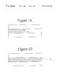
- the general capillarity equation of Young and Laplacedescribes the pressure difference across a meniscus necessary to keep the system in mechanical equilibrium. This equation demonstrates that the pressure difference ⁇ P depends on only the surface tension ⁇ (i.e., the surface free energy per unit area of the meniscus, with units of ergs/cm 2 ) and the shape of the meniscus.
- ⁇ P⁇ (1 /R 1 +1 /R 2 ) (1)
- the meniscusis a three-dimensional surface, the shape of which is described by its radii of curvature (R 1 and R 2 ) in two orthogonal planes. Calculation of the meniscus shape generally requires the sophisticated mathematical tools of differential geometry. However, a wetted capillary in the shape of a simple circular cylinder has a meniscus with a very simple shape as shown in FIG. 1 A.
- the capillary forcescan be calculated directly from the capillary device geometry (i.e., the capillary diameter).
- the capillary channelends abruptly, normal to a plane surface as shown in FIG. 1B, the shape of the meniscus flattens out as the meniscus approaches the opening because the meniscus surface is no longer constrained to be parallel to the capillary wall.
- the radius of curvature of the meniscus r′suddenly becomes infinite (a plane), and the pressure difference ⁇ P across the meniscus vanishes.
- the end of a capillaryembodies a device geometry that traps a meniscus and holds it in mechanical equilibrium. The disappearance of the wetted capillary wall changes the boundary conditions that determine the shape of the meniscus, creating a barrier to movement of the meniscus and the liquid behind it.
- a first element of this inventioncomprises a capillary gate that uses these menisci to control the movement of a liquid.
- a second system element of this invention for effecting formation or removal of menisci in a capillary streamis referred to herein as a “storage volume”.
- storage volumeas used herein should not be construed as requiring that the liquid actually be stored in the volume for any period of time.
- a system elementwhich includes a storage volume having a height of a capillary, which storage volume is in fluid communication with at least two capillary conduits.
- the storage volumehas a width larger than the width of a capillary so that the storage volume is capable of retaining a larger volume of liquid per unit length as compared to the volume stored in a capillary of the same unit length.
- the storage volumealso is in fluid communication with a gas having a controlled pressure thereby permitting the storage volume to function as a pressure control point on a liquid in the storage volume.
- a meniscusis formed within the storage volume at the interface of a liquid directed to the storage volume from an inlet capillary conduit and the gas supplied to the storage volume.
- the shape of this meniscusis a hemi-toroid, a mathematically simple shape having two constant radii of curvature R 1 and R 2 over its surface.
- the liquidis passed from the storage volume into an outlet capillary conduit
- the liquid in the outlet capillary conduitextends from the storage volume to a capillary gate at the end of the outlet capillary conduit, where a second meniscus is formed on the liquid surface in the outlet capillary conduit that contacts a gas in the capillary gate.
- the capillary gatefunctions as a valve. Control of liquid flow is based on the fact that the meniscus forces at the capillary gate arrest the flow of liquid in the outlet capillary conduit unless hydrostatic pressure exerted on the liquid in the outlet capillary conduit exceeds the meniscus forces.
- the capillary gateis a structure similar or identical to the storage volume, wherein the width of the outlet capillary conduit increases abruptly in one dimension to create a barrier to the motion of a fluid front (meniscus), thereby forming a gating point.
- the capillary gateis an opening of the outlet capillary conduit on a surface, wherein the width of the outlet capillary conduit increases abruptly in two dimensions.
- a drain capillary conduit openingin order for the flow to continue past the gate within a capillary, a drain capillary conduit opening must be positioned on a second surface facing and very close to the outlet capillary conduit, thereby allowing a transient liquid bridge to form between the outlet capillary conduit and the drain capillary conduit.
- the volume of liquid in the outlet capillary conduit extending from the storage volume to the capillary gatecan be dispensed in the same manner as emptying a conventional pipette.
- Gas pressure in the storage volumeis impressed on the liquid in the outlet capillary conduit.
- An increase of this gas pressurecauses the precise liquid volume in the outlet capillary conduit to move through the capillary gate into the drain capillary conduit.
- Accuracy of the liquid volumes so dispensedis determined by the dimension of the outlet capillary conduit and not by timing of a presumed liquid flow rate.
- Pressure in the capillary gatecan be increased after the transfer to facilitate the transport of the liquid in the drain capillary conduit to the point of use.
- Gas pressures in a plurality of storage volumes and capillary gates positioned in different fluid pathscan be controlled simultaneously so that complex fluid flow systems can be produced.
- Delivery from the outlet capillary conduit, which functions as a nanopipetteis a transient event consisting of moving a defined volume of liquid from the outlet capillary conduit to the drain capillary conduit, or another point of use of the liquid.
- a system elementis also provided for controlling the gas pressures of the plurality of gas conduits in communication with various storage volumes and capillary gates.
- Implementation of the control scheme of this inventionrequires that the gas pressures be changed at a plurality of control points, causing transitions between stable states of the microfluidic circuit that result in movement of fluid packets.
- the changes in pressures at these control pointsshould be synchronized, and the magnitudes of the pressures should be both accurate and precise (preferably within 0.01 psi).
- the pressurescan be electronically programmable both upward and downward, and it would be desirable that the response time be fast (preferably within about 20 milliseconds).
- a simple electronic pneumatic controlleris described which is suitable for multinode, programmable control.
- This controlleruses proportional control feedback from a silicon pressure transducer.
- FIGS. 1A and 1Bare axial section views of a meniscus in a circular cylindrical capillary.
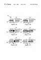
- FIGS. 2A, 2 B, 2 C, 2 D and 2 Eshow five different embodiments of a capillary gate.
- FIGS. 3A, 3 B, 3 C, 3 D, 3 E and 3 Fschematically depict the operation of a capillary gate in transporting liquid through a bridge from one capillary conduit to a second capillary conduit.
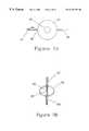
- FIGS. 4A and 4Bare perspective views of two embodiments of a storage volume.
- FIG. 5is a top cross-sectional view of the storage volume of FIG. 4 A.
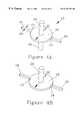
- FIGS. 6A, 6 B and 6 Cillustrate filling of a storage volume of one embodiment of this invention with a liquid.
- FIGS. 7A, 7 B, 7 C and 7 Dillustrate a system for the delivery of precise volumes of liquid in accordance with one embodiment of this invention.
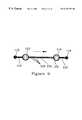
- FIG. 8is a cross section of a capillary made by isotropic etching showing the typical aspect ratio of height (etching depth) to width.
- FIG. 9illustrates the process of one embodiment of this invention for introducing and removing gas bubbles from a capillary liquid stream.
- FIGS. 10A, 10 B, 10 C, 10 D, and 10 Eillustrate a system for mixing liquid samples in accordance with one embodiment of this invention.
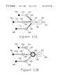
- FIGS. 11A and 11Billustrate a system for combining fixed volumes of three different liquids in accordance with one embodiment of this invention.
- FIG. 12illustrates a system for processing a plurality of liquid samples in a parallel fashion by means of pneumatic control through manifolds common to several similar fluid circuits in accordance with one embodiment of this invention.
- FIG. 13shows a mechanical schematic diagram of a pneumatic controller element in accordance with one embodiment of this invention operating on one node contained in a microfluidic circuit.
- FIG. 14shows an electronic schematic diagram for the pneumatic controller element of FIG. 13, suitable for regulating the pressure at a single node of the microfluidic circuit.
- meniscus controlis the basic principle that supplants mechanical valve closures at very small dimensions.
- the present inventionis based upon the provision of system elements that are capable of forming and positioning a first meniscus on a liquid capillary stream and subsequently of forming and positioning a second meniscus on the capillary stream.
- the formation of a first and second meniscuspermits application of pressure on the menisci which, in turn, permits the positioning of the menisci, which accomplishes the formation of precise volumes of liquid and the movement of such precise volumes of liquid to a desired position.
- the meniscus controlpermits mixing of liquids and division of samples into sub-samples when desired.
- the present inventionprovides a process, system and system elements which permits the formation of and transportation of precise volumes of liquids through capillary paths to a point of use and permits the treatment or analysis of liquid samples in small volumes as small as nanoliter volumes.
- a first system element of this inventionis the capillary gate, of which five different embodiments are shown in FIGS. 2A, 2 B, 2 C, 2 D and 2 E.
- a capillary gateis an abrupt expansion in at least one direction in the cross-sectional dimensions of a capillary, thereby changing the shape of the meniscus as it moves through the gating point and creating a barrier to the motion of the meniscus.
- the pressure difference ⁇ P across the meniscuswill decrease (as in the embodiment of FIG. 2A) or it will vanish (as in the embodiments of FIGS. 2B, 2 C, and 2 D). In either case, the suitable application of pneumatic and hydrostatic control pressures can fix the meniscus in mechanical equilibrium at the gating point.
- the dimensions of the capillary 44increase along one axis (normal to the axis of the capillary) at point 48 , creating a barrier to motion at that point.
- a pressuresufficient to overcome the forces holding the meniscus at the gating point permits the flow of the liquid sample to resume, allowing for the delivery of known quantities of liquid to a point of use.
- the dimensions of the inlet capillary 52increase along two orthogonal axes (both normal to the axis of the capillary) to form a cavity 50 .
- a short gapseparates the gating point 56 from the mouth 58 of a drain capillary 54 .
- This gapis sufficient to arrest the movement of the meniscus unless the hydrostatic pressure in the capillary 52 is great enough to extrude the liquid into the cavity. This pressure will breach the barrier at the gating point 56 by forming a liquid bridge across the gap.
- the barrier to motion of a meniscus across the gap in this embodimentis approximately twice as great as the barrier of FIG. 2A (with capillaries of similar dimensions).
- the third embodiment of FIG. 2Cis a slot 68 cut at right angles through a capillary 62 and 64 to create a gap in the capillary between points 60 and 66 .
- this gaparrests meniscus movement, but allows the formation of a liquid bridge to a drain capillary 64 when the pressure applied to the volume of liquid in the meniscus is sufficient to overcome the forces maintaining the meniscus at the gate.
- a fourth embodiment shown in FIG. 2Dis formed as an intersection of a gas conduit 61 formed through a capillary 62 and 64 such as by drilling, forming a gap between points 66 and 68 .
- This embodimentis a variant of the previous embodiment 2 C.
- a fifth embodiment of a capillary gate, shown in FIG. 2E,does not have an expansion perpendicular to the axis of the capillary, but rather a structure similar to that of a Lang-Levy micropipette. Although the expansion is more gradual than an orthogonal wall, it still serves to arrest the motion of a meniscus by causing the meniscus to flatten out at the gating point indicated by reference numeral 45 .
- the capillary gates shown in embodiments 2 B, 2 C and 2 Dutilize gaps to create the gating point.
- the gapcreates a two-dimensional gating point, the effect of which is to require liquid to bridge the gap in order to move beyond the gate into the next capillary, or into another point of use of the liquid.
- the outlet capillary conduit 74is closed to further liquid flow. The liquid will move into the gap 72 as illustrated in FIG. 3B only when the hydraulic pressure in the capillary 74 exceeds a threshold pressure determined by the Young-Laplace equation, i.e., the meniscus free energy at the end of the outlet capillary conduit 74 .
- Bridging of the capillary gate 70is a transient, dynamic event.
- the minimum volume sufficient to bridge the gapdepends upon the dimensions of each gate design.
- the minimum liquid bridging volumeis an important parameter because it is the lower limit on delivery volumes for this type of capillary gate.
- the capillary gate described abovecan be utilized in combination with a storage volume to produce precise volumes of liquid in the system of this invention.
- FIGS. 4A, 4 B and 5illustrate one embodiment of the storage volume or housing of this invention for forming, gating and removing menisci in and from a capillary stream.
- the storage volume 16includes an inlet capillary conduit 18 , an outlet capillary conduit 20 , and an interior volume 16 having a dimension substantially larger than that of a capillary conduit such as inlet capillary conduit 18 or outlet capillary conduit 20 .
- the capillary dimension expansion created by volume 16should be at least about two times the capillary width (or height).
- the width of the storage volumeat its largest dimension as indicated by arrow 22 , should be at least about five times as large and preferably at least about ten times as large as the width of a capillary as indicated by arrow 24 .
- the purpose of the larger width in storage volume 16is to cause a capillary stream of liquid entering the storage volume 16 from inlet capillary conduit 18 to be split into two sub-streams 17 and 19 which contact the perimeter 26 of the storage volume 16 when a gas is present in interior volume 16 through conduit 28 as shown in FIG. 5, thereby forming a meniscus at the liquid-gas interface.
- Conduit 28can extend to one surface of the storage volume 16 as shown in FIG. 4B, or to both surfaces of the storage volume 16 as shown in FIG. 4 A.
- the latter arrangement shown in FIG. 4Aincludes a conduit section 29 .
- the widths of the sub-streams of 17 and 19can be controlled by the gas pressure within storage volume 16 through gas conduit 28 .
- the thickness of the sub-streams 17 and 19proceeds from the outer radius of storage volume 16 inwardly toward the gas conduit 28 .
- a meniscus 30 or 32is formed as an interface between the liquid sub-streams 17 and 19 and the gas within volume 16 introduced through gas conduit 28 .
- any bubble entering the storage volume 16 through inlet capillary conduit 18fuses with the meniscus 30 or 32 within storage volume 16 and is removed from the liquid stream.
- the formation of the meniscus 30 or 32permits the formation of precise volumes of liquid within a capillary conduit and permits the transportation of these precise volumes of liquid to a desired point of use.
- FIGS. 7A, 7 B, 7 C and 7 Dshow one manner in which storage volumes and capillaries are used according to the invention to create and move a precise volume of liquid.
- the volume of outlet capillary conduit 94is filled with a liquid from reservoir 98 by passing the liquid from reservoir 98 , through inlet capillary conduit 96 , through storage volume 90 and into outlet capillary conduit 94 to fill outlet capillary conduit 94 with liquid.
- the liquidfills the outlet capillary conduit 94 up to the intersection 95 of the outlet capillary conduit 94 and storage volume 92 .
- This intersection 95is a capillary gate.
- the volume of liquid in the outlet capillary conduit 94defines the desired precise volume of liquid to be delivered to a point of use as described hereinafter.
- FIG. 7Bwhen the pressure in storage volume 90 is increased, liquid in inlet capillary conduit 96 is directed back to reservoir 98 , thereby creating a new meniscus at capillary gate 91 .
- the pressure difference between the pressures in volumes 90 and 92remains below the threshold of the meniscus at the capillary gate 95 (the ⁇ P in the Young-Laplace equation), thereby causing the liquid in this outlet capillary conduit to remain stationary and become isolated from the reservoir 98 .
- Typical dimensions of capillaries 96 , 94 and 100are a width between about 5 micrometers and about 100 micrometers, preferably between about 20 micrometers and about 75 micrometers and a height between about 1 micrometer and about 30 micrometers, preferably between about 10 micrometers and about 20 micrometers.
- Typical dimensions for the storage volume 90comprise a diameter of between about 100 micrometers and about 1000 micrometers, preferably between about 200 micrometers and about 500 micrometers and a height within the same range as the capillaries (as the capillaries and storage volumes are usually etched together).
- the storage volumeneed not have a circular cross section but can have any cross section so long that a meniscus can be formed by providing gas thereto.
- the cross sectional shape of storage volume 90can be square, rectangular, triangular, polygonal or the like.
- the volume of the storage volumecan be controlled by defining its major dimension so that it can store a desired volume of liquid. When the liquid within the storage volume reaches the gas conduit, the storage volume is full.
- Typical diameters for a capillary gate 92are similar to those for the storage volume 90 .
- Capillary gates shown in embodiments of FIGS. 2B, 2 C, and 2 Dhave gaps between 10 microns and 30 microns wide, the smaller gaps requiring a smaller minimum volume for forming a liquid bridge across the gap.
- the gas conduitneed not be centrally located within the storage volume.
- FIG. 9shows a system element of this invention for introducing bubbles into a capillary.
- Liquid from reservoir 116is passed under pressure into inlet capillary conduit 118 and thence into storage volume 110 wherein a meniscus is formed.
- the sampleis split and then recombined for entry into outlet capillary conduit 120 .
- a bubble 124is introduced into the outlet capillary conduit by momentarily increasing the pressure within storage volume 110 so that the meniscus in volume 100 is moved into and along outlet capillary conduit 120 .
- the pressures in storage volume 110 and in reservoir 116are regulated so that liquid passes from reservoir 116 , through a storage volume 110 and into the outlet capillary conduit 120 .
- the pressure within storage volume 112is adjusted so that bubbles 124 in outlet capillary conduit 120 are removed from the liquid by being merged with a new meniscus 57 formed in storage volume 112 .
- the pressure in storage volume 112also is regulated so that no bubbles are transported into capillary conduit 122 .
- a detection meanssuch as a refractive index detector for detecting the presence or absence of liquid samples can be installed into outlet capillary conduit 120 between storage volume 110 and storage volume 112 so that sub-samples formed from bubbles interposed therebetween can be separately analyzed or reacted as desired.
- FIGS. 10A-10Ea system element of this invention is shown which can be utilized to agitate a liquid sample initially present in the storage volume 132 , as might be needed if frequent or additional mixing is necessary.
- the pressures within storage volumes 134 and 136 and within storage volumes 130 and 132are controlled so that the majority of liquid is transferred from storage volume 132 into the storage volume 130 through a capillary conduit 140 .
- This sequenceis then reversed to transfer the liquid back into the storage volume 132 , causing liquid shear through the capillary that effects mixing of the solution.
- FIGS. 10D and 10Eshow the same system element as FIGS. 10A, 10 B, and 10 C, except that FIG. 10D has two unmixed liquid samples segregated by a bubble in capillary conduit 140 . If the sum of the sample volumes is less than the volume of either storage volume 130 and 132 , then these two separate volumes can be mixed in a manner similar to that shown in FIGS. 10A, 10 B, and 10 C. Such a system can be utilized, for example to react two liquids within the system of this invention.
- a supply of liquid stored in reservoir 160which could be a first reagent for carrying out chemical synthesis is moved under pressure control to fill the capillary conduit 170 , the storage volume 154 , and the capillary conduit 176 .
- a second liquid reagent stored in reservoir 162is moved to fill the capillary conduit 172 , the storage volume 156 , and the capillary conduit 178 .
- a third liquid reagent stored in reservoir 164is moved to fill the capillary conduit 174 , the storage volume 158 , and the capillary conduit 180 .
- FIG. 11Arepresents the state previously described for FIG. 7B, just prior to transferring the fixed volumes in capillary conduits 176 , 178 and 180 through the storage volume 150 (as shown in FIG. 11 B). These transfers may preferably occur simultaneously.
- the transfereffects mixing of the three fixed volumes of liquid transferred from capillary conduits 176 , 178 and 180 to the destination storage volume 152 to produce a desired synthesis reaction. Further mixing could be accomplished by a device similar to one described in reference to FIG. 10 A. Diffusion within the small dimensions shown here will also enable mixing of the three liquid volumes.
- the storage volume 152can function as a point of use, or it could be in fluid communication with an analytical device such as an electrophoresis capillary or the like.
- the general application of using the storage volumes and capillary gates of the present inventioninvolves setting the pressures simultaneously at a multiplicity of control points such that a transition takes place, thereby controlling the movement of a liquid from one point to another point in the fluid circuit. Such movement is arrested by the geometry of the capillary gate to produce a new stable state, and that stable state persists until the pressures at the multiplicity of control nodes are again changed to initiate a new transition to a different stable state of the fluid circuit.
- non-simultaneous pressurescan be used to initially cause a first liquid to mix with a second, and subsequently cause a third liquid to mix with the mixed first and second liquids. Referring to FIG. 12, a plurality of subsystems identical to that device shown in FIG.
- 11Aare arranged adjacent to each other in an array, and their corresponding gas conduits are connected together by means of the gas conduit manifolds 196 , 194 , 192 and 190 .
- the three devices showntherefore can be controlled in parallel by pneumatic control elements in communication with each of the gas conduit manifolds.
- Two of the pipetting storage volumes of each subsystemi.e., 156 and 189 ) are shown on the same control manifold, and these pipettes operate in a synchronized fashion.
- Manifolds 200 and 198contain liquids which feed corresponding pipettes 164 and 160 , whereas the inlet reservoirs 162 , 186 and 188 are not in communication with a manifold because they receive different liquid samples from one subsystem to the next.
- the subsystems shown in FIG. 12are isolated and independent from each other. This arrangement of subsystems is particularly suited for multiplex operation and is useful in high throughput screening of potential candidates in drug discovery processes.
- FIG. 13shows a mechanical schematic diagram of a gas pressure control element used to communicate with one of the gas conduit manifolds of FIG. 12.
- a microfluidic circuit 215has an opening (not shown) on its surface communicating with one of the gas manifolds.
- a conduit 230forms a spring loaded face-seal with this opening by means of the O-ring 210 , the ferrule 212 , and the compression spring 225 , and conduit 230 is in communication with an accumulator 236 wherein the pressure is measured by a pressure transducer 238 .
- An electronic feedback loopconsisting of the pressure transducer 238 , a control circuit 242 , a pressurizing valve 250 and a relieving valve 252 , all joined by signal leads 240 , 248 and 244 , establishes whether the pressurizing valve 250 is open or closed, and whether the relieving valve 252 is open or closed, thereby changing the pressure in the accumulator 236 as needed.
- the pressurizing valve 250is in communication with a source of elevated pressure 256
- the relieving valve 252is in communication with a source 255 of lower pressure or with a vacuum.
- FIG. 14shows an electronic schematic diagram of the control circuit 242 , one element of the feedback loop shown in FIG. 13 .
- the signal from the pressure transducer 260is amplified by an instrumentation amplifier 265 , and is routed to the summing points 285 and 287 of two operational amplifiers 271 and 273 . Also routed to the summing points 287 and 285 of amplifiers 271 and 273 are corresponding offset voltages from the voltage followers 272 and 274 , as well as a sawtooth signal made by the astable multivibrator 280 .
- the signals emanating from the amplifiers 271 and 273are therefore sawtooth waveforms that rise and fall with respect to the baseline as the pressure in transducer 260 falls and rises.
- variable voltage source 290which may be a digital-to-analog converter (DAC) in communication with a computer
- the voltage comparators 277 and 278cause the pressurizing valve 266 or the relieving valve 267 to open and close at the same frequency as the sawtooth signal, but for longer or shorter periods, or not at all, depending on the relation of the sawtooth waveform to the setpoint voltage from voltage source 290 .
- DACdigital-to-analog converter
- This type of circuitis known in the art as a proportional controller.
- the duty cycle of the valve controlling the gas pressureis proportional to the error in the pressure.
- the intervals during which the valve is openbecome shorter and shorter.
- the duty cycle of the valvebecomes zero as the desired pressure is achieved. This allows a response time as fast as the valve can open or close, without overshooting the desired setpoint pressure.
- the signal from the pressure transducer 260can be amplified to assure that the pneumatic controller will respond to very small changes in pressure, with a preferred precision in the regulated gas pressure of ⁇ 0.01 psi.
- the pressuremay be recorded or monitored by a device 270 , which may be an analog-to-digital converter in communication with a computer.
- the setpoint voltages from the voltage source 290 under the direction from a computercan be calibrated to correspond to specific pressures.
- the offset voltages from voltage followers 272 and 274are chosen such that the pressurizing valve and the relieving valve are never actuated at the same time.
- the prior art in electronic regulation of gas pressureteaches several methods, of which the preferred is a proportional-integral-derivative (PID) response to an error in the pressure.
- the PID methodis typically embodied in an algorithm executed by a microprocessor, with the intention of achieving a high level of stability at one fixed pressure under varying loads.
- the pneumatic controller of the present inventionachieves a somewhat different end by making an inexpensive hardware proportional controller with the objective of changing the pressure frequently and accurately at a multiplicity of control nodes.
- the pressure changesare synchronized at the multiplicity of control nodes and a multiplicity of desired setpoint pressures can be obtained at each of the multiplicity of control nodes. In this manner, the formation and effective transport of precise liquid volumes within a complex microfluidic circuit can be accomplished with negligible impact on the gas pressure control.
- microfluidic circuits or devicesSuch devices can take a variety of forms, but they are generally characterized as planar structures having a plurality of ports for introducing or withdrawing liquids to and from the device, one or more reservoirs for storing liquid samples or liquid reagents, and a plurality of capillary scale channels for transporting and/or mixing liquids, conducting chemical analyses, separating components of a mixture or the like.
- the microfluidic devices as well as the system and system elements of this inventioncan be formed by conventional photolithography and etching techniques or by molding plastic compositions which are well known in the art.
- suitable substrates from which the system and system elements of this invention can be formedinclude glass, quartz, silicon, polycarbonate, polymethylmethacrylate or the like. However, the wetting characteristics of these different substrates must be taken into account for proper design of the fluid circuits.
Landscapes
- Chemical & Material Sciences (AREA)
- Health & Medical Sciences (AREA)
- Chemical Kinetics & Catalysis (AREA)
- Dispersion Chemistry (AREA)
- Analytical Chemistry (AREA)
- General Health & Medical Sciences (AREA)
- Hematology (AREA)
- Clinical Laboratory Science (AREA)
- Sampling And Sample Adjustment (AREA)
- Automatic Analysis And Handling Materials Therefor (AREA)
- Feeding, Discharge, Calcimining, Fusing, And Gas-Generation Devices (AREA)
Abstract
Description
Claims (29)
Priority Applications (5)
| Application Number | Priority Date | Filing Date | Title |
|---|---|---|---|
| US09/345,072US6193471B1 (en) | 1999-06-30 | 1999-06-30 | Pneumatic control of formation and transport of small volume liquid samples |
| PCT/US2000/017735WO2001001106A1 (en) | 1999-06-30 | 2000-06-26 | Pneumatic control of formation and transport of small volume liquid samples |
| EP00943231AEP1192437B1 (en) | 1999-06-30 | 2000-06-26 | Pneumatic control of formation and transport of small volume liquid samples |
| JP2001506473AJP2003503184A (en) | 1999-06-30 | 2000-06-26 | Pneumatic control of the formation and transport of small liquid samples |
| DE60033394TDE60033394T2 (en) | 1999-06-30 | 2000-06-26 | PNEUMATIC CONTROL OF THE FORMATION AND TRANSPORT OF LIQUID SAMPLES |
Applications Claiming Priority (1)
| Application Number | Priority Date | Filing Date | Title |
|---|---|---|---|
| US09/345,072US6193471B1 (en) | 1999-06-30 | 1999-06-30 | Pneumatic control of formation and transport of small volume liquid samples |
Publications (1)
| Publication Number | Publication Date |
|---|---|
| US6193471B1true US6193471B1 (en) | 2001-02-27 |
Family
ID=23353376
Family Applications (1)
| Application Number | Title | Priority Date | Filing Date |
|---|---|---|---|
| US09/345,072Expired - LifetimeUS6193471B1 (en) | 1999-06-30 | 1999-06-30 | Pneumatic control of formation and transport of small volume liquid samples |
Country Status (5)
| Country | Link |
|---|---|
| US (1) | US6193471B1 (en) |
| EP (1) | EP1192437B1 (en) |
| JP (1) | JP2003503184A (en) |
| DE (1) | DE60033394T2 (en) |
| WO (1) | WO2001001106A1 (en) |
Cited By (45)
| Publication number | Priority date | Publication date | Assignee | Title |
|---|---|---|---|---|
| US6296452B1 (en)* | 2000-04-28 | 2001-10-02 | Agilent Technologies, Inc. | Microfluidic pumping |
| WO2001090614A2 (en) | 2000-05-24 | 2001-11-29 | Micronics, Inc. | Surface tension valves for microfluidic applications |
| US6481453B1 (en) | 2000-04-14 | 2002-11-19 | Nanostream, Inc. | Microfluidic branch metering systems and methods |
| US20020186263A1 (en)* | 2001-06-07 | 2002-12-12 | Nanostream, Inc. | Microfluidic fraction collectors |
| US20020187560A1 (en)* | 2001-06-07 | 2002-12-12 | Nanostream, Inc. | Microfluidic systems and methods for combining discrete fluid volumes |
| US20020195343A1 (en)* | 2001-06-20 | 2002-12-26 | Coventor, Inc. | Microfabricated separation device employing a virtual wall for interfacing fluids |
| US20020197733A1 (en)* | 2001-06-20 | 2002-12-26 | Coventor, Inc. | Microfluidic system including a virtual wall fluid interface port for interfacing fluids with the microfluidic system |
| US6499499B2 (en) | 2001-04-20 | 2002-12-31 | Nanostream, Inc. | Flow control in multi-stream microfluidic devices |
| US20030005967A1 (en)* | 2001-07-07 | 2003-01-09 | Nanostream, Inc. | Microfluidic metering systems and methods |
| US20030015425A1 (en)* | 2001-06-20 | 2003-01-23 | Coventor Inc. | Microfluidic system including a virtual wall fluid interface port for interfacing fluids with the microfluidic system |
| US6591852B1 (en) | 1998-10-13 | 2003-07-15 | Biomicro Systems, Inc. | Fluid circuit components based upon passive fluid dynamics |
| US20030133358A1 (en)* | 2002-01-11 | 2003-07-17 | Nanostream, Inc. | Multi-stream microfluidic aperture mixers |
| US6601613B2 (en) | 1998-10-13 | 2003-08-05 | Biomicro Systems, Inc. | Fluid circuit components based upon passive fluid dynamics |
| US20030159742A1 (en)* | 2002-02-23 | 2003-08-28 | Nanostream, Inc. | Microfluidic multi-splitter |
| US6632400B1 (en)* | 2000-06-22 | 2003-10-14 | Agilent Technologies, Inc. | Integrated microfluidic and electronic components |
| US20030198130A1 (en)* | 2000-08-07 | 2003-10-23 | Nanostream, Inc. | Fluidic mixer in microfluidic system |
| US6637463B1 (en) | 1998-10-13 | 2003-10-28 | Biomicro Systems, Inc. | Multi-channel microfluidic system design with balanced fluid flow distribution |
| US6662818B2 (en)* | 2002-02-01 | 2003-12-16 | Perseptive Biosystems, Inc. | Programmable tracking pressure regulator for control of higher pressures in microfluidic circuits |
| FR2841158A1 (en)* | 2002-06-24 | 2003-12-26 | Bio Merieux | THERMO-PNEUMATICALLY FLEXIBLE FLUID DEVICE ISOLATION AND POSSIBLY AGITATION OF THE CONTENT OF AN OPERATIVE CAVITY |
| US20040063217A1 (en)* | 2002-09-27 | 2004-04-01 | Webster James Russell | Miniaturized fluid delivery and analysis system |
| US20040091398A1 (en)* | 2001-06-20 | 2004-05-13 | Teragenics, Inc. | Microfluidic system including a virtual wall fluid interface port for interfacing fluids with the microfluidic system |
| US20040141884A1 (en)* | 1999-08-19 | 2004-07-22 | Caliper Technologies Corp. | Indicator components for microfluidic systems |
| US6890093B2 (en) | 2000-08-07 | 2005-05-10 | Nanostream, Inc. | Multi-stream microfludic mixers |
| US20050169778A1 (en)* | 2003-12-20 | 2005-08-04 | Gert Blankenstein | Microstructured arrangement for the bubble-free filling with a liquid of at least one system for draining off liquids, apparatus having such an arrangement and filling method |
| US20060006065A1 (en)* | 2004-06-05 | 2006-01-12 | Symyx Technologies, Inc. | Microfluidic fluid distribution manifold for use with multi-channel reactor systems |
| US20060204699A1 (en)* | 2004-12-08 | 2006-09-14 | George Maltezos | Parylene coated microfluidic components and methods for fabrication thereof |
| US20060263264A1 (en)* | 2001-06-20 | 2006-11-23 | Cytonome, Inc | Microfluidic system including a virtual wall fluid interface port for interfacing fluids with the microfluidic system |
| US20080013092A1 (en)* | 2006-05-19 | 2008-01-17 | George Maltezos | Fluorescence detector, filter device and related methods |
| US20080069733A1 (en)* | 2006-09-18 | 2008-03-20 | George Maltezos | Apparatus for detecting target molecules and related methods |
| US20080083465A1 (en)* | 2006-10-10 | 2008-04-10 | George Maltezos | Microfluidic devices and related methods and systems |
| US7412990B2 (en) | 2003-12-22 | 2008-08-19 | Electronics And Telecommunications Research Institute | Microfluidic control device and method for controlling microfluid |
| US20100120635A1 (en)* | 2003-09-05 | 2010-05-13 | Stokes Bio Limited | Sample dispensing |
| WO2010126449A1 (en)* | 2009-04-27 | 2010-11-04 | Agency For Science, Technology And Research | Apparatus and method for dispensing a liquid |
| US20130112300A1 (en)* | 2006-02-07 | 2013-05-09 | Stokes Bio Limited | Liquid bridge and system |
| US8695355B2 (en) | 2004-12-08 | 2014-04-15 | California Institute Of Technology | Thermal management techniques, apparatus and methods for use in microfluidic devices |
| US20150182964A1 (en)* | 2013-12-30 | 2015-07-02 | General Electric Company | Fluid transport in microfluidic applications |
| US9533304B2 (en) | 2006-02-07 | 2017-01-03 | Stokes Bio Limited | Forming sample combinations using liquid bridge systems |
| US9597644B2 (en) | 2003-09-05 | 2017-03-21 | Stokes Bio Limited | Methods for culturing and analyzing cells |
| US9983105B2 (en)* | 2011-04-02 | 2018-05-29 | Biosurfit, S.A. | Liquid reagent storage and operation of analytical devices |
| US10180133B2 (en) | 2013-11-22 | 2019-01-15 | Rheonix, Inc. | Channel-less pump, methods, and applications thereof |
| US10676786B2 (en) | 2003-09-05 | 2020-06-09 | Stokes Bio Ltd. | Microfluidic analysis system |
| US10994273B2 (en) | 2004-12-03 | 2021-05-04 | Cytonome/St, Llc | Actuation of parallel microfluidic arrays |
| US11027278B2 (en) | 2002-04-17 | 2021-06-08 | Cytonome/St, Llc | Methods for controlling fluid flow in a microfluidic system |
| US11865541B2 (en) | 2020-06-12 | 2024-01-09 | Biofluidica, Inc. | Dual-depth thermoplastic microfluidic device and related systems and methods |
| US12390805B2 (en) | 2017-04-20 | 2025-08-19 | Biofluidica, Inc. | Methods of isolating biomarker cells |
Families Citing this family (8)
| Publication number | Priority date | Publication date | Assignee | Title |
|---|---|---|---|---|
| WO2006092959A1 (en)* | 2005-03-01 | 2006-09-08 | Rohm Co., Ltd | Microchannel and microfluid chip |
| JP4637610B2 (en)* | 2005-03-02 | 2011-02-23 | ローム株式会社 | Microchannel and microchip |
| US11306351B2 (en) | 2005-12-21 | 2022-04-19 | Affymetrix, Inc. | Methods for genotyping |
| ATE477844T1 (en) | 2006-02-07 | 2010-09-15 | Stokes Bio Ltd | MICROFLUID NETWORK FOR FORMING A SNAKE OF DROPlets AND METHOD |
| US8735169B2 (en) | 2006-02-07 | 2014-05-27 | Stokes Bio Limited | Methods for analyzing agricultural and environmental samples |
| DE102009000529A1 (en)* | 2009-01-30 | 2010-08-19 | INSTITUT FüR MIKROTECHNIK MAINZ GMBH | Microfluidic chip with pressure measuring device |
| EP2426497A1 (en)* | 2010-09-02 | 2012-03-07 | Ludwig-Maximilians-Universität München | Generation and use of liquid stacks in microchannels or capillaries |
| EP3897987A1 (en)* | 2018-12-20 | 2021-10-27 | TECAN Trading AG | Method of treating a sample |
Citations (6)
| Publication number | Priority date | Publication date | Assignee | Title |
|---|---|---|---|---|
| US3929411A (en)* | 1972-09-14 | 1975-12-30 | Hitachi Ltd | Sample transfer device and method for analytical system |
| US4367043A (en)* | 1980-05-05 | 1983-01-04 | Leland Stanford Junior University | Method and means for delivering liquid samples to a sample scanning device |
| US4399362A (en)* | 1981-02-27 | 1983-08-16 | Instrumentation Laboratory Inc. | Liquid handling apparatus |
| US4415011A (en)* | 1981-11-02 | 1983-11-15 | Isco, Inc. | Sample collector |
| US5015591A (en)* | 1987-10-15 | 1991-05-14 | Nivarox-Far S.A. | Method and apparatus for filtering and metering liquid samples |
| US5788819A (en)* | 1992-10-27 | 1998-08-04 | Canon Kabushiki Kaisha | Method for driving liquid, and method and apparatus for mixing and agitation employing the method |
Family Cites Families (9)
| Publication number | Priority date | Publication date | Assignee | Title |
|---|---|---|---|---|
| JPS4847889A (en)* | 1971-10-14 | 1973-07-06 | ||
| EP0048917B1 (en)* | 1980-09-30 | 1985-12-27 | CARLO ERBA STRUMENTAZIONE S.p.A. | A method and apparatus for volumetrically controlled and reproducible introduction of small amounts of liquid samples into chromatographic analysis systems |
| US4426451A (en)* | 1981-01-28 | 1984-01-17 | Eastman Kodak Company | Multi-zoned reaction vessel having pressure-actuatable control means between zones |
| US4868129A (en)* | 1987-08-27 | 1989-09-19 | Biotrack Inc. | Apparatus and method for dilution and mixing of liquid samples |
| CA1333850C (en)* | 1987-08-27 | 1995-01-10 | Michael M. Gorin | Apparatus and method for dilution and mixing of liquid samples |
| US4936465A (en)* | 1987-12-07 | 1990-06-26 | Zoeld Tibor | Method and apparatus for fast, reliable, and environmentally safe dispensing of fluids, gases and individual particles of a suspension through pressure control at well defined parts of a closed flow-through system |
| US5104813A (en)* | 1989-04-13 | 1992-04-14 | Biotrack, Inc. | Dilution and mixing cartridge |
| EP0501796A3 (en)* | 1991-03-01 | 1993-10-06 | Biotrack, Inc. | Capillary stop-flow junction having improved stability against accidental fluid flow |
| US20010055812A1 (en)* | 1995-12-05 | 2001-12-27 | Alec Mian | Devices and method for using centripetal acceleration to drive fluid movement in a microfluidics system with on-board informatics |
- 1999
- 1999-06-30USUS09/345,072patent/US6193471B1/ennot_activeExpired - Lifetime
- 2000
- 2000-06-26WOPCT/US2000/017735patent/WO2001001106A1/enactiveIP Right Grant
- 2000-06-26EPEP00943231Apatent/EP1192437B1/ennot_activeExpired - Lifetime
- 2000-06-26JPJP2001506473Apatent/JP2003503184A/enactivePending
- 2000-06-26DEDE60033394Tpatent/DE60033394T2/ennot_activeExpired - Lifetime
Patent Citations (6)
| Publication number | Priority date | Publication date | Assignee | Title |
|---|---|---|---|---|
| US3929411A (en)* | 1972-09-14 | 1975-12-30 | Hitachi Ltd | Sample transfer device and method for analytical system |
| US4367043A (en)* | 1980-05-05 | 1983-01-04 | Leland Stanford Junior University | Method and means for delivering liquid samples to a sample scanning device |
| US4399362A (en)* | 1981-02-27 | 1983-08-16 | Instrumentation Laboratory Inc. | Liquid handling apparatus |
| US4415011A (en)* | 1981-11-02 | 1983-11-15 | Isco, Inc. | Sample collector |
| US5015591A (en)* | 1987-10-15 | 1991-05-14 | Nivarox-Far S.A. | Method and apparatus for filtering and metering liquid samples |
| US5788819A (en)* | 1992-10-27 | 1998-08-04 | Canon Kabushiki Kaisha | Method for driving liquid, and method and apparatus for mixing and agitation employing the method |
Cited By (81)
| Publication number | Priority date | Publication date | Assignee | Title |
|---|---|---|---|---|
| US6591852B1 (en) | 1998-10-13 | 2003-07-15 | Biomicro Systems, Inc. | Fluid circuit components based upon passive fluid dynamics |
| US6637463B1 (en) | 1998-10-13 | 2003-10-28 | Biomicro Systems, Inc. | Multi-channel microfluidic system design with balanced fluid flow distribution |
| US6601613B2 (en) | 1998-10-13 | 2003-08-05 | Biomicro Systems, Inc. | Fluid circuit components based upon passive fluid dynamics |
| US20040141884A1 (en)* | 1999-08-19 | 2004-07-22 | Caliper Technologies Corp. | Indicator components for microfluidic systems |
| US6481453B1 (en) | 2000-04-14 | 2002-11-19 | Nanostream, Inc. | Microfluidic branch metering systems and methods |
| US6296452B1 (en)* | 2000-04-28 | 2001-10-02 | Agilent Technologies, Inc. | Microfluidic pumping |
| WO2001090614A2 (en) | 2000-05-24 | 2001-11-29 | Micronics, Inc. | Surface tension valves for microfluidic applications |
| US6632400B1 (en)* | 2000-06-22 | 2003-10-14 | Agilent Technologies, Inc. | Integrated microfluidic and electronic components |
| US20030198130A1 (en)* | 2000-08-07 | 2003-10-23 | Nanostream, Inc. | Fluidic mixer in microfluidic system |
| US6890093B2 (en) | 2000-08-07 | 2005-05-10 | Nanostream, Inc. | Multi-stream microfludic mixers |
| US6935772B2 (en) | 2000-08-07 | 2005-08-30 | Nanostream, Inc. | Fluidic mixer in microfluidic system |
| US6499499B2 (en) | 2001-04-20 | 2002-12-31 | Nanostream, Inc. | Flow control in multi-stream microfluidic devices |
| US20020187560A1 (en)* | 2001-06-07 | 2002-12-12 | Nanostream, Inc. | Microfluidic systems and methods for combining discrete fluid volumes |
| US7318912B2 (en) | 2001-06-07 | 2008-01-15 | Nanostream, Inc. | Microfluidic systems and methods for combining discrete fluid volumes |
| US20020186263A1 (en)* | 2001-06-07 | 2002-12-12 | Nanostream, Inc. | Microfluidic fraction collectors |
| US20020195343A1 (en)* | 2001-06-20 | 2002-12-26 | Coventor, Inc. | Microfabricated separation device employing a virtual wall for interfacing fluids |
| US20030015425A1 (en)* | 2001-06-20 | 2003-01-23 | Coventor Inc. | Microfluidic system including a virtual wall fluid interface port for interfacing fluids with the microfluidic system |
| US20020197733A1 (en)* | 2001-06-20 | 2002-12-26 | Coventor, Inc. | Microfluidic system including a virtual wall fluid interface port for interfacing fluids with the microfluidic system |
| US20070148777A1 (en)* | 2001-06-20 | 2007-06-28 | Cytonome, Inc. | Microfluidic system including a virtual wall fluid interface port for interfacing fluids with the microfluidic system |
| US7211442B2 (en) | 2001-06-20 | 2007-05-01 | Cytonome, Inc. | Microfluidic system including a virtual wall fluid interface port for interfacing fluids with the microfluidic system |
| US7179423B2 (en) | 2001-06-20 | 2007-02-20 | Cytonome, Inc. | Microfluidic system including a virtual wall fluid interface port for interfacing fluids with the microfluidic system |
| US20060263264A1 (en)* | 2001-06-20 | 2006-11-23 | Cytonome, Inc | Microfluidic system including a virtual wall fluid interface port for interfacing fluids with the microfluidic system |
| US20040091398A1 (en)* | 2001-06-20 | 2004-05-13 | Teragenics, Inc. | Microfluidic system including a virtual wall fluid interface port for interfacing fluids with the microfluidic system |
| US20030005967A1 (en)* | 2001-07-07 | 2003-01-09 | Nanostream, Inc. | Microfluidic metering systems and methods |
| US7077152B2 (en) | 2001-07-07 | 2006-07-18 | Nanostream, Inc. | Microfluidic metering systems and methods |
| US6877892B2 (en) | 2002-01-11 | 2005-04-12 | Nanostream, Inc. | Multi-stream microfluidic aperture mixers |
| US20030133358A1 (en)* | 2002-01-11 | 2003-07-17 | Nanostream, Inc. | Multi-stream microfluidic aperture mixers |
| WO2003067355A3 (en)* | 2002-02-01 | 2004-03-04 | Perseptive Biosystems Inc | Programmable tracking pressure regulator for control of higher pressures in microfluidic circuits |
| US6662818B2 (en)* | 2002-02-01 | 2003-12-16 | Perseptive Biosystems, Inc. | Programmable tracking pressure regulator for control of higher pressures in microfluidic circuits |
| US6845787B2 (en) | 2002-02-23 | 2005-01-25 | Nanostream, Inc. | Microfluidic multi-splitter |
| US20030159742A1 (en)* | 2002-02-23 | 2003-08-28 | Nanostream, Inc. | Microfluidic multi-splitter |
| US11027278B2 (en) | 2002-04-17 | 2021-06-08 | Cytonome/St, Llc | Methods for controlling fluid flow in a microfluidic system |
| WO2004000449A1 (en)* | 2002-06-24 | 2003-12-31 | bioMérieux | Hydraulic device for the thermo-pneumatic insulation and optional agitation of the contents of an operative cavity |
| FR2841158A1 (en)* | 2002-06-24 | 2003-12-26 | Bio Merieux | THERMO-PNEUMATICALLY FLEXIBLE FLUID DEVICE ISOLATION AND POSSIBLY AGITATION OF THE CONTENT OF AN OPERATIVE CAVITY |
| CN100377770C (en)* | 2002-06-24 | 2008-04-02 | 比奥梅里欧公司 | Hydraulic device for the thermo-pneumatic isolation and optional agitation of the contents of an operative cavity |
| US20070020147A1 (en)* | 2002-09-27 | 2007-01-25 | Agnitio Science & Technology | Miniaturized fluid delivery and analysis system |
| US20070020148A1 (en)* | 2002-09-27 | 2007-01-25 | Agnitio Science & Technology | Miniaturized fluid delivery and analysis system |
| US20070031287A1 (en)* | 2002-09-27 | 2007-02-08 | Agnitio Science & Technology | Miniaturized fluid delivery and analysis system |
| US7666687B2 (en) | 2002-09-27 | 2010-02-23 | James Russell Webster | Miniaturized fluid delivery and analysis system |
| US8323887B2 (en) | 2002-09-27 | 2012-12-04 | James Russell Webster | Miniaturized fluid delivery and analysis system |
| US20100105065A1 (en)* | 2002-09-27 | 2010-04-29 | James Russell Webster | Miniaturized Fluid Delivery and Analysis System |
| US7241421B2 (en) | 2002-09-27 | 2007-07-10 | Ast Management Inc. | Miniaturized fluid delivery and analysis system |
| US20040063217A1 (en)* | 2002-09-27 | 2004-04-01 | Webster James Russell | Miniaturized fluid delivery and analysis system |
| US8968659B2 (en) | 2003-09-05 | 2015-03-03 | Stokes Bio Limited | Sample dispensing |
| US11807902B2 (en) | 2003-09-05 | 2023-11-07 | Stokes Bio Ltd. | Microfluidic analysis system |
| US10676786B2 (en) | 2003-09-05 | 2020-06-09 | Stokes Bio Ltd. | Microfluidic analysis system |
| US10967338B2 (en) | 2003-09-05 | 2021-04-06 | Stokes Bio Ltd. | Methods of releasing and analyzing cellular components |
| US20100120635A1 (en)* | 2003-09-05 | 2010-05-13 | Stokes Bio Limited | Sample dispensing |
| US9597644B2 (en) | 2003-09-05 | 2017-03-21 | Stokes Bio Limited | Methods for culturing and analyzing cells |
| US20050169778A1 (en)* | 2003-12-20 | 2005-08-04 | Gert Blankenstein | Microstructured arrangement for the bubble-free filling with a liquid of at least one system for draining off liquids, apparatus having such an arrangement and filling method |
| US7485118B2 (en) | 2003-12-20 | 2009-02-03 | Boehringer Ingelholm Microparts Gmbh | Microstructured arrangement for the bubble-free filling with a liquid of at least one system for draining off liquids, apparatus having such an arrangement and filing method |
| EP1559676A3 (en)* | 2003-12-20 | 2008-12-03 | Boehringer Ingelheim microParts GmbH | Microstructured device and method for bubble-free filling of a device for guiding liquids |
| US7412990B2 (en) | 2003-12-22 | 2008-08-19 | Electronics And Telecommunications Research Institute | Microfluidic control device and method for controlling microfluid |
| US7758814B2 (en) | 2004-06-05 | 2010-07-20 | Freeslate, Inc. | Microfluidic fluid distribution manifold for use with multi-channel reactor systems |
| US20060006065A1 (en)* | 2004-06-05 | 2006-01-12 | Symyx Technologies, Inc. | Microfluidic fluid distribution manifold for use with multi-channel reactor systems |
| US10994273B2 (en) | 2004-12-03 | 2021-05-04 | Cytonome/St, Llc | Actuation of parallel microfluidic arrays |
| US20070012891A1 (en)* | 2004-12-08 | 2007-01-18 | George Maltezos | Prototyping methods and devices for microfluidic components |
| US8695355B2 (en) | 2004-12-08 | 2014-04-15 | California Institute Of Technology | Thermal management techniques, apparatus and methods for use in microfluidic devices |
| US20060204699A1 (en)* | 2004-12-08 | 2006-09-14 | George Maltezos | Parylene coated microfluidic components and methods for fabrication thereof |
| US10730051B2 (en)* | 2006-02-07 | 2020-08-04 | Stokes Bio Ltd. | Liquid bridge and system |
| US12350671B2 (en) | 2006-02-07 | 2025-07-08 | Stokes Bio Limited | Liquid bridge and system |
| US9322511B2 (en)* | 2006-02-07 | 2016-04-26 | Stokes Bio Limited | Liquid bridge and system |
| US9533304B2 (en) | 2006-02-07 | 2017-01-03 | Stokes Bio Limited | Forming sample combinations using liquid bridge systems |
| US20130112300A1 (en)* | 2006-02-07 | 2013-05-09 | Stokes Bio Limited | Liquid bridge and system |
| US11772096B2 (en) | 2006-02-07 | 2023-10-03 | Stokes Bio Ltd. | System for processing biological sample |
| US8137626B2 (en) | 2006-05-19 | 2012-03-20 | California Institute Of Technology | Fluorescence detector, filter device and related methods |
| US20080013092A1 (en)* | 2006-05-19 | 2008-01-17 | George Maltezos | Fluorescence detector, filter device and related methods |
| US8187541B2 (en) | 2006-09-18 | 2012-05-29 | California Institute Of Technology | Apparatus for detecting target molecules and related methods |
| US20080069733A1 (en)* | 2006-09-18 | 2008-03-20 | George Maltezos | Apparatus for detecting target molecules and related methods |
| US7814928B2 (en) | 2006-10-10 | 2010-10-19 | California Institute Of Technology | Microfluidic devices and related methods and systems |
| US20080083465A1 (en)* | 2006-10-10 | 2008-04-10 | George Maltezos | Microfluidic devices and related methods and systems |
| WO2010126449A1 (en)* | 2009-04-27 | 2010-11-04 | Agency For Science, Technology And Research | Apparatus and method for dispensing a liquid |
| US11964244B2 (en) | 2009-11-12 | 2024-04-23 | Stokes Bio Limited | Methods of releasing and analyzing cellular components |
| US9983105B2 (en)* | 2011-04-02 | 2018-05-29 | Biosurfit, S.A. | Liquid reagent storage and operation of analytical devices |
| US11248596B2 (en) | 2013-11-22 | 2022-02-15 | Rheonix, Inc. | Channel-less pump, methods, and applications thereof |
| US10180133B2 (en) | 2013-11-22 | 2019-01-15 | Rheonix, Inc. | Channel-less pump, methods, and applications thereof |
| US9399216B2 (en)* | 2013-12-30 | 2016-07-26 | General Electric Company | Fluid transport in microfluidic applications with sensors for detecting fluid presence and pressure |
| US20150182964A1 (en)* | 2013-12-30 | 2015-07-02 | General Electric Company | Fluid transport in microfluidic applications |
| US12390805B2 (en) | 2017-04-20 | 2025-08-19 | Biofluidica, Inc. | Methods of isolating biomarker cells |
| US11865541B2 (en) | 2020-06-12 | 2024-01-09 | Biofluidica, Inc. | Dual-depth thermoplastic microfluidic device and related systems and methods |
| US12350669B2 (en) | 2020-06-12 | 2025-07-08 | Biofluidica, Inc. | Dual-depth thermoplastic microfluidic device and related systems and methods |
Also Published As
| Publication number | Publication date |
|---|---|
| DE60033394D1 (en) | 2007-03-29 |
| WO2001001106A1 (en) | 2001-01-04 |
| JP2003503184A (en) | 2003-01-28 |
| EP1192437A1 (en) | 2002-04-03 |
| EP1192437B1 (en) | 2007-02-14 |
| DE60033394T2 (en) | 2007-10-31 |
Similar Documents
| Publication | Publication Date | Title |
|---|---|---|
| US6193471B1 (en) | Pneumatic control of formation and transport of small volume liquid samples | |
| Sammarco et al. | Thermocapillary pumping of discrete drops in microfabricated analysis devices | |
| AU2003204633B2 (en) | Device for displacement of small liquid volumes along a micro-catenary line by electrostatic forces | |
| Sharp et al. | Liquid flows in microchannels | |
| US8652852B2 (en) | Method of pumping fluid through a microfluidic device | |
| US7171983B2 (en) | Multi-reservoir pressure control system | |
| EP1386079B1 (en) | A liquid pumping system | |
| US7094379B2 (en) | Device for parallel and synchronous injection for sequential injection of different reagents | |
| JP3732159B2 (en) | Method and apparatus for processing fluid in substrate | |
| Suk et al. | Capillary flow control using hydrophobic patterns | |
| Greenwood et al. | Sample manipulation in micro total analytical systems | |
| US20020046948A1 (en) | Microfluidic devices and methods to regulate hydrodynamic and electrical resistance utilizing bulk viscosity enhancers | |
| KR970705020A (en) | Apparatus and method for performing precise flow control for chemical analysis and synthesis | |
| US20090268548A1 (en) | Microfluidic systems, devices and methods for reducing diffusion and compliance effects at a fluid mixing region | |
| US8394645B2 (en) | Method for performing a high throughput assay | |
| Ishida et al. | First-come-first-store microfluidic device of droplets using hydrophobic passive microvalves | |
| US20070295372A1 (en) | Device for passive microfluidic washing using capillary force | |
| Puntambekar et al. | Fixed-volume metering microdispenser module | |
| JP2003200041A (en) | Device for injecting various reactants successively and synchronously in parallel | |
| Duan et al. | A facile method for microfluidic metering and transport | |
| Puntambekar et al. | A new fixed-volume metering microdispenser module based on sPROMs technology | |
| KR102711038B1 (en) | Microfluidic system | |
| Juncker et al. | Microfluidic capillary systems for the autonomous transport of bio/chemicals | |
| Yager | Transverse diffusion in microfluidic systems | |
| CN113661007A (en) | System and device for injecting droplets in a microfluidic system |
Legal Events
| Date | Code | Title | Description |
|---|---|---|---|
| AS | Assignment | Owner name:PERSEPTIVE BIOSYSTEMS, INC., MASSACHUSETTS Free format text:ASSIGNMENT OF ASSIGNORS INTEREST;ASSIGNOR:PAUL, CARLTON H.;REEL/FRAME:010076/0073 Effective date:19990630 | |
| STCF | Information on status: patent grant | Free format text:PATENTED CASE | |
| FEPP | Fee payment procedure | Free format text:PAYOR NUMBER ASSIGNED (ORIGINAL EVENT CODE: ASPN); ENTITY STATUS OF PATENT OWNER: LARGE ENTITY | |
| FPAY | Fee payment | Year of fee payment:4 | |
| FPAY | Fee payment | Year of fee payment:8 | |
| REMI | Maintenance fee reminder mailed | ||
| AS | Assignment | Owner name:BANK OF AMERICA, N.A., AS COLLATERAL AGENT, WASHIN Free format text:SECURITY AGREEMENT;ASSIGNOR:PERSEPTIVE BIOSYSTEMS, INC.;REEL/FRAME:021976/0160 Effective date:20081121 | |
| FPAY | Fee payment | Year of fee payment:12 | |
| AS | Assignment | Owner name:APPLIED BIOSYSTEMS, INC., CALIFORNIA Free format text:LIEN RELEASE;ASSIGNOR:BANK OF AMERICA, N.A.;REEL/FRAME:030182/0677 Effective date:20100528 | |
| AS | Assignment | Owner name:APPLIED BIOSYSTEMS, LLC, CALIFORNIA Free format text:MERGER;ASSIGNOR:PERSEPTIVE BIOSYSTEMS, INC.;REEL/FRAME:031907/0696 Effective date:20090407 | |
| AS | Assignment | Owner name:APPLIED BIOSYSTEMS, LLC, CALIFORNIA Free format text:CORRECTIVE ASSIGNMENT TO CORRECT THE RECEIVING PARTY NAME PREVIOUSLY RECORDED AT REEL: 030182 FRAME: 0718. ASSIGNOR(S) HEREBY CONFIRMS THE RELEASE OF SECURITY INTEREST;ASSIGNOR:BANK OF AMERICA, N.A.;REEL/FRAME:038038/0134 Effective date:20100528 Owner name:APPLIED BIOSYSTEMS, LLC, CALIFORNIA Free format text:CORRECTIVE ASSIGNMENT TO CORRECT THE RECEIVING PARTY NAME PREVIOUSLY RECORDED AT REEL: 030182 FRAME: 0677. ASSIGNOR(S) HEREBY CONFIRMS THE RELEASE OF SECURITY INTEREST;ASSIGNOR:BANK OF AMERICA, N.A.;REEL/FRAME:038038/0134 Effective date:20100528 |