US6193399B1 - Optical waveguide structures for vehicle lighting - Google Patents
Optical waveguide structures for vehicle lightingDownload PDFInfo
- Publication number
- US6193399B1 US6193399B1US09/062,766US6276698AUS6193399B1US 6193399 B1US6193399 B1US 6193399B1US 6276698 AUS6276698 AUS 6276698AUS 6193399 B1US6193399 B1US 6193399B1
- Authority
- US
- United States
- Prior art keywords
- waveguide
- light
- ring portion
- cup holder
- input face
- Prior art date
- Legal status (The legal status is an assumption and is not a legal conclusion. Google has not performed a legal analysis and makes no representation as to the accuracy of the status listed.)
- Expired - Lifetime
Links
Images


Classifications
- B—PERFORMING OPERATIONS; TRANSPORTING
- B60—VEHICLES IN GENERAL
- B60N—SEATS SPECIALLY ADAPTED FOR VEHICLES; VEHICLE PASSENGER ACCOMMODATION NOT OTHERWISE PROVIDED FOR
- B60N3/00—Arrangements or adaptations of other passenger fittings, not otherwise provided for
- B60N3/10—Arrangements or adaptations of other passenger fittings, not otherwise provided for of receptacles for food or beverages, e.g. refrigerated
- B—PERFORMING OPERATIONS; TRANSPORTING
- B60—VEHICLES IN GENERAL
- B60Q—ARRANGEMENT OF SIGNALLING OR LIGHTING DEVICES, THE MOUNTING OR SUPPORTING THEREOF OR CIRCUITS THEREFOR, FOR VEHICLES IN GENERAL
- B60Q3/00—Arrangement of lighting devices for vehicle interiors; Lighting devices specially adapted for vehicle interiors
- B60Q3/20—Arrangement of lighting devices for vehicle interiors; Lighting devices specially adapted for vehicle interiors for lighting specific fittings of passenger or driving compartments; mounted on specific fittings of passenger or driving compartments
- B60Q3/225—Small compartments, e.g. glove compartments
- B60Q3/229—Cup holders
- B—PERFORMING OPERATIONS; TRANSPORTING
- B60—VEHICLES IN GENERAL
- B60Q—ARRANGEMENT OF SIGNALLING OR LIGHTING DEVICES, THE MOUNTING OR SUPPORTING THEREOF OR CIRCUITS THEREFOR, FOR VEHICLES IN GENERAL
- B60Q3/00—Arrangement of lighting devices for vehicle interiors; Lighting devices specially adapted for vehicle interiors
- B60Q3/60—Arrangement of lighting devices for vehicle interiors; Lighting devices specially adapted for vehicle interiors characterised by optical aspects
- B60Q3/62—Arrangement of lighting devices for vehicle interiors; Lighting devices specially adapted for vehicle interiors characterised by optical aspects using light guides
- B60Q3/64—Arrangement of lighting devices for vehicle interiors; Lighting devices specially adapted for vehicle interiors characterised by optical aspects using light guides for a single lighting device
- G—PHYSICS
- G02—OPTICS
- G02B—OPTICAL ELEMENTS, SYSTEMS OR APPARATUS
- G02B6/00—Light guides; Structural details of arrangements comprising light guides and other optical elements, e.g. couplings
- G02B6/0001—Light guides; Structural details of arrangements comprising light guides and other optical elements, e.g. couplings specially adapted for lighting devices or systems
- G02B6/0005—Light guides; Structural details of arrangements comprising light guides and other optical elements, e.g. couplings specially adapted for lighting devices or systems the light guides being of the fibre type
- G02B6/0006—Coupling light into the fibre
- G—PHYSICS
- G02—OPTICS
- G02B—OPTICAL ELEMENTS, SYSTEMS OR APPARATUS
- G02B6/00—Light guides; Structural details of arrangements comprising light guides and other optical elements, e.g. couplings
- G02B6/10—Light guides; Structural details of arrangements comprising light guides and other optical elements, e.g. couplings of the optical waveguide type
- G02B6/12—Light guides; Structural details of arrangements comprising light guides and other optical elements, e.g. couplings of the optical waveguide type of the integrated circuit kind
- G02B2006/12083—Constructional arrangements
- G02B2006/12119—Bend
- G—PHYSICS
- G02—OPTICS
- G02B—OPTICAL ELEMENTS, SYSTEMS OR APPARATUS
- G02B6/00—Light guides; Structural details of arrangements comprising light guides and other optical elements, e.g. couplings
- G02B6/10—Light guides; Structural details of arrangements comprising light guides and other optical elements, e.g. couplings of the optical waveguide type
- G02B6/12—Light guides; Structural details of arrangements comprising light guides and other optical elements, e.g. couplings of the optical waveguide type of the integrated circuit kind
- G02B2006/12133—Functions
- G02B2006/1215—Splitter
- G—PHYSICS
- G02—OPTICS
- G02B—OPTICAL ELEMENTS, SYSTEMS OR APPARATUS
- G02B6/00—Light guides; Structural details of arrangements comprising light guides and other optical elements, e.g. couplings
- G02B6/0001—Light guides; Structural details of arrangements comprising light guides and other optical elements, e.g. couplings specially adapted for lighting devices or systems
- G—PHYSICS
- G02—OPTICS
- G02B—OPTICAL ELEMENTS, SYSTEMS OR APPARATUS
- G02B6/00—Light guides; Structural details of arrangements comprising light guides and other optical elements, e.g. couplings
- G02B6/24—Coupling light guides
- G02B6/42—Coupling light guides with opto-electronic elements
- G02B6/4298—Coupling light guides with opto-electronic elements coupling with non-coherent light sources and/or radiation detectors, e.g. lamps, incandescent bulbs, scintillation chambers
Definitions
- the inventionrelates to distributed lighting systems.
- Distributed lighting systemsdistribute light from one or more light sources in central locations to one or more remote locations.
- a distributed lighting systempromises several advantages over conventional lighting techniques, including low power consumption, extended life, heat reduction where the light is emitted, and increased design flexibility.
- the inventionprovides a distributed lighting system (DLS) for use, for example, in an automobile. Issues associated with incorporating a distributed lighting system into an automobile are discussed by Hulse, Lane, and Woodward in “Threee Specific Design Issues Associated with Automotive Distributed Lighting Systems: Size, Efficiency and Reliability,” SAE Technical Paper Series, Paper No. 960492, which was presented at the SAE International Congress and Exposition, Detroit, Mich., Feb. 26-29, 1996 and Hulse and Mullican in “Analysis of Waveguide Geometries at Bends and Branches for the Directing of Light,” SAE Technical Paper Series, Paper No. 981189, which are incorporated herein by reference.
- DLSdistributed lighting system
- an implementation of the inventionemploys focus-less optics components, such as collector elements and waveguides. These components are inexpensive to manufacture, since they can be formed from plastic (acrylic, for example) in an injection molding process. In addition, they have high collecting efficiency and are very compact. For example, a collector element may be smaller than one cubic inch (16.4 cubic centimeters). Components that must handle high heat levels (e.g., components are placed in proximity to the light source) may require a ventilation system or may include portions formed from heat resistant materials, such as glass or PyrexTM.
- the DLSmay incorporate different types of optical waveguide structures to distribute light throughout the vehicle, including joints, elements with epoxy coatings, pinched end collector portions, integrated installation snaps, integrated input optics and integrated output lenses.
- the DLSmay also include waveguide structures to provide illumination to portions of the vehicle interior, including cup holders, assist grips, and storage pockets.
- an optical waveguide for illuminating the interior of a cup holder in a vehicleis formed from a piece of solid material.
- the solid materialhas a ring portion that is sized and shaped to be received within a cup holder and that releases light into the cup holder.
- An input facereceives light from a light source.
- An input portionextends between the input face and the ring portion, confines light through internal reflection, and directs light from the input face to the ring portion.
- Embodimentsmay include one or more of the following features.
- the ring portionmay define an inner circumference and may release light around the inner circumference.
- the ring portionmay have a protruding angled portion around the inner circumference that directs light down toward a bottom portion of the cup holder.
- the upper surface of the angled portionmay be stippled.
- An upper surface of the angled portionmay be covered with an opaque material.
- the ratio of an inner radius of the ring portion to the width of the ring portionmay be greater than or equal to 3:1.
- the ring portionmay include a first arm and a second arm that define a gap in the inner circumference.
- the second armmay have a smaller cross-section and a smaller length than the first arm.
- the ring portionmay have a web portion that extends between the first and second arms. The web portion may release light along its edge.
- the ring portionmay include a tab that extends from the inner circumference between the first and second arms.
- the tabmay have a rectangular cross-section and may curve toward the bottom of the cup holder.
- the tabmay have a chamfered leading edge.
- the optical waveguide described abovemay be included in an illuminated cup holder having a bottom surface.
- a side wallmay extend from the bottom surface and define a volume shaped and sized to receive a cup.
- a rimmay be positioned around the upper edge of the side wall.
- an optical waveguideilluminates the inside of an assist grip in a vehicle.
- the waveguideis a piece of solid material having an illumination portion with an inner surface and an outer surface.
- the illumination portionis sized and shaped to be received within a channel along the length of the assist grip and releases light from the inner surface.
- An input face at one end of the illumination portionreceives light from a light source.
- Embodimentsmay include one or more of the following features.
- the inner surfacemay be stippled.
- the ratio of the inner radius of a bend to the width of the waveguidemay be greater than or equal to 3:1.
- the waveguidemay have snaps extending from the outer surface that hold the illumination portion in place within the channel.
- a lens positioned adjacent to the light sourcemay focus light from the light source to form a courtesy light.
- An illuminated assist grip for a vehicle including the waveguide described abovealso may have a handle portion formed of solid material, a channel formed along the length of the handle and a light source receptacle configured to receive a light source.
- an optical waveguide for a vehicle doorilluminates an area beneath the vehicle.
- the doorhas a bottom surface that meets a floor surface of the vehicle when the door is closed.
- the waveguideincludes a door portion positioned inside the door and extending to the bottom surface of the door.
- a floor portionextends from the floor surface to the underside surface of the vehicle. The door portion and the floor portion meet when the door is closed so that light may pass through the door portion and the floor portion to illuminate the area beneath the vehicle.
- Embodimentsmay include a branch that extends from the door portion to an interior surface of the door to illuminate the interior of the vehicle.
- an illuminated storage pocket for a vehiclehas a surface that defines a storage volume and a rim around an edge of the surface.
- a waveguide formed from a piece of solid materialhas an illumination portion that has an inner surface and an outer surface. The illumination portion is received within a channel along the rim of the storage pocket and releases light from the inner surface.
- An input face at one end of the illumination portionreceives light from a light source.
- Embodimentsmay include one or more of the following features.
- the inner surface of the waveguidemay be stippled.
- the waveguidemay include snaps that extend from the outer surface and hold the illumination portion in place within the channel.
- an optical waveguidein another aspect, includes a first and a second piece of solid material.
- the first piecehas a transmission portion with a rectangular cross-section.
- the end of the transmission portionis convex in one dimension.
- the second piecehas a transmission portion with a rectangular cross-section.
- the end of the transmission portionis concave in one dimension.
- the end of the first piece and the end of the second pieceform an interface between the first and second pieces.
- Embodimentsmay include one or more of the following features.
- the waveguidemay include a third piece of solid material having a transmission portion with a rectangular cross-section.
- the end of the transmission portionmay be concave in one dimension.
- the end of the third piece and the end of the first piecemay form an interface between the first and third pieces.
- a bandmay hold the first, second and third pieces together.
- the waveguidemay include a third piece of solid material having a transmission portion with a rectangular cross-section.
- the end of the transmission portionmay be convex in one dimension.
- the end of the third piece and the end of the second pieceform an interface between the second and third pieces.
- a bandmay hold the first, second and third pieces together.
- an optical waveguideaccepts light from a light source and transmits the light.
- the waveguideis formed from a piece of solid material having an input face, a transmission portion and an end portion between the input face and the transmission portion. A cross-sectional area of the end portion gradually decreases from the transmission portion to the input portion.
- Embodimentsmay include one or more of the following features.
- the end portionmay have planar sides angled from a longitudinal axis of the transmission portion. The angle formed between the sides and the longitudinal axis may be about 5°.
- the end portionmay increase the acceptance angle of the waveguide.
- a lens portionmay be formed on the input face.
- an optical waveguidehas integrated installation elements.
- the waveguideincludes first and second sections.
- the first sectionhas an input face, an output end and a transmission portion extending from the input face to the output end.
- a keyis positioned on the output end and mates with a socket of the second section.
- the second sectionhas an input face, an output end and a transmission portion extending from the input face to the output end.
- a socketis positioned on the output end and mates with the key of the first section.
- Embodimentsmay include one or more of the following features.
- the waveguidemay include a snap positioned on the transmission portion of the first or second section.
- the snapmay mate with an installation fitting of a vehicle.
- the outer surface of the waveguidemay be covered with epoxy.
- an optical waveguidehas integrated installation elements.
- the waveguideincludes first and second sections.
- the first sectionhas an input face, an output end and a transmission portion extending from the input face to the output end.
- a clawis positioned on the output end and mates with a detent of the second section.
- the second sectionhas an input face, an output end and a transmission portion extending from the input face to the output end.
- a detentis positioned near the output end and mates with the claw of the first section.
- Embodimentsmay include one or more of the following features.
- a snapmay be positioned on the transmission portion and may mate with an installation fitting of a vehicle.
- An outer surface of the waveguidemay be covered with epoxy.
- an optical waveguidehas an output element for providing illumination in a vehicle.
- the waveguideincludes an input face and a transmission portion extending from the input face.
- the transmission portionwidens at an end to form an output element having a convex lens at the end of the output element.
- the output elementmay be formed to leave an air gap between the lens and the end of the transmission portion.
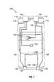
- FIG. 1is a block diagram of a vehicle distributed lighting system with hybrid lighting subsystems.
- FIG. 2shows a hybrid headlamp subsystem
- FIG. 3shows a hybrid headlamp subsystem with a movable lens.
- FIGS. 4A-4Dshow headlamp beam forming structures.
- FIG. 5shows a light source with a diffusion grating.
- FIGS. 6A-6Fshow waveguide outputs modulated with electromechanical or liquid crystal light valves.
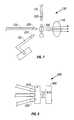
- FIG. 7shows a hybrid tail light subsystem
- FIG. 8shows a compact incandescent cartridge.
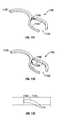
- FIGS. 9A and 9Bshow a waveguide output bend for a tail light.
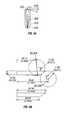
- FIGS. 10A and 10Bshow a combination security/puddle light.
- FIGS. 11A-11Fshow various embodiments of a cup holder illumination component.
- FIG. 12Ais a rear view of a waveguide installed in a handgrip.
- FIG. 12Bis a cross-section view of a waveguide and light source installed in a handgrip.
- FIG. 12Cshows a waveguide with integrated snaps for installation into a handgrip.
- FIG. 13is a cross-section view of an optical waveguide.
- FIGS. 14A and 14Bare side and bottom views of a waveguide joint.
- FIG. 15is a cross-section view of an epoxy-coated optical waveguide.
- FIGS. 16A-16Care cross-section views of non-tapered and tapered waveguide inputs.
- FIGS. 17A and 17Bare cross-section views of waveguide sections having integrated installation components and an integrated output structure.
- FIG. 18shows a leaky waveguide bend and focusing lens.
- FIGS. 19A and 19Bshow cross-section views of optical manifolds.
- a vehicle distributed lighting system (DLS) 100includes hybrid headlamp subsystems 105 , turn signal subsystems 110 and 140 , and hybrid tail light subsystems 130 .
- the hybrid headlamp subsystems 105provide primary forward illumination for the vehicle.
- the headlamp subsystems 105are also light sources for other exterior lights, such as front turn signals of the subsystems 110 and side markers 115 , as well as interior lights, such as dashboard lights 120 and dome lights 125 . These other lights are connected to the headlamp subsystems by optical waveguides 135 .
- the tail light subsystems 130provide light for rear turn signals 140 and a center high mounted stop light (CHMSL) 145 .
- the subsystems of the DLSare interconnected so that the light source of one subsystem serves as a redundant light source for another subsystem.
- the DLSincorporates different types of optical waveguide structures to distribute light throughout the vehicle. These include joints, elements with epoxy coatings, pinched end collector portions, integrated installation snaps, integrated input optics and integrated output lenses.
- the DLSalso includes waveguide structures to provide illumination to portions of the vehicle interior, including cup holders, assist grips, and storage pockets.
- FIG. 2illustrates a hybrid headlamp subsystem 105 .
- the subsystemincludes a light source 205 that may be implemented using, for example, a high-intensity discharge (HID) lamp.
- Light produced by the light source 205is collected by a reflector 210 and directed through a lens 215 to provide the primary forward illumination for the vehicle.
- the reflectormay be implemented as a parabolic or complex reflector.
- the hybrid headlamp subsystem 105provides both high beam and low beam illumination.
- the subsystemmay employ a number of different beam forming techniques, as shown in FIGS. 3-5.
- FIG. 3shows a simple Fresnel lens 305 that is moved by an actuator 310 between a high beam position and a low beam position.
- the movement of the lens 305shifts the position of the “hot spot” (i.e., the area of most concentrated light) of the headlamp beam in the far field between the appropriate positions for the high and low beams.
- Other portions of the beamalso will shift as the lens moves.
- other optical elementssuch as wedges, may be used to control the beam pattern.
- FIGS. 4A-4Dshow the use of a solid molded plastic form 405 (FIGS. 4A-4C) or a bundle of plastic or glass fibers 410 (FIG. 4D) to generate a desired headlamp beam pattern.
- Light from light source 205passes through the form 405 or bundles 410 and then passes through a focusing lens 415 .
- the shape of the input end 425 of the solid formmay be configured to act as a collector element to receive light from a light source.
- a reflector 215may also be used to control the beam pattern, as in FIGS. 2 and 3.
- the lens 305may be moved to shift the hot spot of the beam between high beam and low beam positions.
- FIG. 5shows the use of a diffraction grating 500 to control the headlamp beam pattern (the diffraction grating may also be used for other lighting functions, such as stop lights and turn signals).
- the grating 500may provide, for example, a more focused headlamp beam in the far field.
- the grating 500may be used alone or in conjunction with lenses 305 , solid forms 405 or fiber bundles 410 described above to provide a desired headlamp beam pattern.
- the light source 205acts as a light source for other parts of the system.
- waveguides 135 having collector elements 220 at their endsare positioned close to the light source 205 to receive light and transmit the light to other locations in the vehicle, such as to provide turn signals, interior lighting, fog lights, and side markers.
- the waveguides 135may also carry light to other lighting subsystems to provide redundancy, such as the opposite side headlamp or the tail lights.
- the number of collector elements 220may be increased as necessary to supply light for other lighting functions.
- the collector elements 220may be glass rods (such as Pyrex) with ends that are polished so as to be faceted or pinched. The pinched ends increase the acceptance angle of the collector element.
- FIG. 2shows a waveguide 225 that carries light from the source to a side marker light 115 .
- the waveguide 225may include colored plastic filters 230 to provide a desired output color (e.g., amber) for the side marker 115 . This configuration eliminates the need for an electrical connection and light bulb in the side marker 115 .
- the turn signal subsystem 110may include an independent light source and may use the input from the headlamp subsystem 105 for redundancy.
- some implementations of the turn signal subsystemuse an electromechanical shutter 605 (FIGS. 6A and 6B) while others use a liquid crystal light valve (LCLV) 610 (FIGS. 6C and 6D) to modulate the light produced by the turn signal.
- LCLVliquid crystal light valve
- a plastic colored filterprovides amber color for the turn signal. The use of a colored filter eliminates the need for light bulbs enclosed in cadmium-doped glass.
- the electromechanical modulator 605includes an opaque shutter 615 that is moved between an ON (FIG. 6A) and OFF (FIG. 6B) position by a solenoid 620 .
- the ON positionthe shutter 615 is moved away from the illumination path, so that essentially all of the light is transmitted.
- the OFF positionthe shutter 615 blocks the illumination path so that no light is transmitted.
- an electromechanical modulator 605 with an amber-colored plastic filterprovides a desirable aesthetic effect (i.e., the turn signal appears amber when ON but has no color when OFF).
- the LCLV illustrated in FIGS. 6C and 6Dhas no mechanical components. This increases the reliability of the LCLV relating to systems that include mechanical components.
- the LCLV 610has two states. In the OFF state (FIG. 6D) the LCLV 610 reflects or scatters most of incident light. In the ON state (FIG. 6C) the LCLV 610 becomes largely transparent (i.e., greater than 80% of incident light passes through the LCLV).
- the ratio of the light transmitted in the ON state relative to the light transmitted in the OFF statei.e., the contrast ratio
- a contrast ratio of 5:1also meets the SAE requirements for stop lights used as turn signals.
- An infrared reflecting mirror(not shown) may be used to shield the LCLV from infrared energy from the source, thereby increasing the expected life of the LCLV.
- LCLV modulators 610may be combined with diffraction gratings 500 to improve the contrast ratio and achieve a desired beam pattern.
- light from the light source(waveguide 135 ) is scattered when the LCLV is OFF (FIG. 6 F).
- the diffraction grating 500lessens the amount of forward scattered light that is emitted.
- Focusing opticssuch as lenses 630 , may also be used to provide further beam pattern control.
- waveguidesalso may carry light from the headlamp subsystem to other subsystems that have their own light sources, such as the opposite headlamp subsystem (waveguide 137 ) or the corresponding tail light subsystem (waveguide 138 ), to provide light source redundancy.
- redundancyWhen redundancy is employed and, for example, one of the headlamps fails, light from the operational headlamp will dimly illuminate the failed headlamp. This is safer for the operator of the vehicle than having only one operational headlamp. Redundancy also may be used to reduce the effects of failure of other lighting components.
- an incandescent PC bulbmay be used as a source for trunk lighting and may be connected to provide redundancy to interior reading lights.
- the tail light subsystems 130 of FIG. 1operate similarly to the headlamp subsystems.
- a tail light subsystem 130has a light source 705 that provides primary rear illumination through a lens 710 .
- the light source 705may be a HID lamp or another type of lighting source, such as an incandescent lamp, since the lighting requirement (in lumens) generally is less than the requirement for a headlamp.
- an incandescent sourceis significantly less expensive than an HID source.
- a compact incandescent cartridge 800such as shown in FIG. 8, may be employed as the light source 705 .
- the cartridge 800includes a housing 805 having reflective, heat-dissipating interior surfaces 810 .
- An incandescent bulb 815is positioned in the center of the housing 805 .
- Waveguide collector elements 220are positioned around the light source.
- the incandescent cartridge 800has a compact size, stays cool, and reduces lamp placement error, which increases efficiency.
- construction of the waveguide collector elements 220 from injection moldingis easy and inexpensive.
- the cartridge 800 or similar incandescent sourcesmay also be used as light sources elsewhere in the DLS, depending on lighting requirements.
- networks of cartridges 800 or incandescent sourcesmay be interconnected to provide redundant light sources for interior or exterior lighting functions in the DLS.
- waveguide collector elements 220 in the tail light subsystemare positioned close to the source 705 to receive light and transmit the light to other lighting elements, such as the rear turn signals 140 , backup lights 150 , and center high-mounted stop light (CHMSL) 145 .
- a combination stop/rear turn signal lightmay be modulated with a LCLV 610 , as discussed above with respect to the forward turn signals.
- the backup lights 150 and CHMSL 145are modulated with electromechanical shutters 615 , since they must be completely dark in the OFF mode.
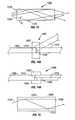
- the rear turn signals subsystems 140also may be implemented in the manner shown in FIGS. 9A and 9B.
- a waveguide section 900may be used to provide a desired beam pattern for the rear turn signal.
- Light from a collector element 220 or an independent light sourceis received at the input 910 of the waveguide section 900 and is internally reflected by the surfaces of the waveguide as it propagates.
- the waveguide 900includes a bend 920 immediately prior to the output 930 .
- the outer surface of the bend 920is s-shaped, which changes the distribution of light across the output surface 930 and hence the far field beam pattern of the turn signal.
- FIG. 9Bshows dimensions in mm [inches] of a waveguide 900 that might be used to provide a desired beam pattern.
- the DLSalso may be used to provide other lighting functions.
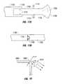
- a waveguide 1000may be installed in the door 1005 , as shown in FIGS. 10A and 10B, to provide a security/puddle light.
- the waveguide 1000runs from a light source, such as the hybrid headlamp subsystem 105 (FIG. 1 ), to the bottom edge 1010 of the door 1005 .
- a waveguide branch 1012may be used to implement a interior door light.
- a door waveguide section 1015connects to a waveguide 1020 that passes through the floor 1025 .
- the floor waveguide section 1020provides a security light that illuminates the area 1030 underneath the vehicle.
- the door 1005is open, as in FIG.
- the door waveguide 1015provides a puddle light that illuminates the ground 1035 between the open door and the vehicle.
- the bend 1040 in the door waveguide section 1015may have a bend angle ( ⁇ B ) of, for example, 20°.
- the bend 1040helps to direct the output of the waveguide 1000 to the desired area.
- the security/puddle lightmay be implemented as a hybrid subsystem that has an independent light source.
- the independent light sourcemay directly provide interior lighting for the vehicle in addition to being connected to the waveguide 1000 as a light source for the security/puddle light.
- Waveguidecarries light from hybrid headlamp subsystem to the interior of the vehicle to provide, for example, dashboard lighting, dome lights, and reading lights. Waveguides also provide unique, aesthetically pleasing lighting effects for certain interior structures, such as cup holders, map pockets, and assist grips.
- a ring-shaped waveguide element 1100may be installed under the lip 1105 of a cup holder 1110 .
- the shape of the waveguide 1100 in FIGS. 11A and 11Bis circular, any shape may be used depending upon the shape and size of the cup holder 1110 .
- the efficiency of the waveguidemay be improved by selecting a ratio of the inner radius (r) of the waveguide relative to the width (w) of the waveguide. For example, a waveguide with an inner radius to waveguide width ratio (r/w) of 3:1 will lose less light than a ratio of 1:1 or 0.1:1.
- the waveguide 1100may have a protruding, angled upper region 1115 to reflect and/or transmit light downward toward the bottom 1120 of the cup holder 1110 .
- the upper surface 1125 of the angled portion 1115may be stippled and may be covered with a layer of opaque material to prevent leakage of light in the upward direction.
- a small incandescent bulb 1130 at the input 1135 of the waveguideis used as a source. Light entering the input 1135 is transmitted to the ring-shaped portion 1136 of the waveguide 1100 via an input portion 1137 that is tangentially connected to the ring-shaped portion 1136 .
- a colored filter 1145may be placed between the source 1130 and the input 1135 to achieve a desired illumination color.
- the interior 1140 of the cup holder 1110When illuminated, the interior 1140 of the cup holder 1110 glows faintly so as not to interfere with the driver's vision. The glowing illumination allows the occupants of the vehicle to discern the location of the cup holder 1110 .
- Light for the waveguide 1100also may be provided by a waveguide 135 connected to one of the lighting subassemblies.
- FIGS. 11C-11DAnother embodiment of the cup holder illumination waveguide 1100 is shown in FIGS. 11C-11D.
- These “wishbone” shaped waveguides 1100are configured for cup holders having a gap 1150 to accommodate a mug handle.
- Light for the waveguide 1100enters the input 1135 and is split essentially equally to the two arms 1155 of the wishbone.
- the split in the waveguide 1100may lead to a dark area in the illumination of the cup holder. Therefore, as shown in FIG. 11C, a web portion 1160 is included between the two arms 1155 .
- the web portionis thinner than the rest of the waveguide 1100 and provides additional illumination to the portion of the interior 1140 of the cup holder directly beneath the split in the wishbone.
- a tab 1165 that is thinner than the rest of the waveguide 1100may extend downward from the split to reflect and/or transmit light toward the bottom of the cup holder.
- the tab 1165has a generally rectangular cross-section and curves downward toward the bottom 1120 of the cup holder.
- the tab 1165may have a chamfered leading edge 1170 .
- FIG. 11 FYet another embodiment of the cup holder illumination waveguide 1100 is shown in FIG. 11 F.
- the waveguide 1100is configured for cup holders having a gap 1150 to accommodate a mug handle.
- Lightenters the input 1135 and is split unequally between a primary arm 1175 and a secondary arm 1180 .
- the secondary armhas a smaller cross-section, (i.e., is thinner and narrower than the primary arm 1175 . Since the secondary arm 1180 is shorter than the primary arm 1175 , there is less loss along its length.
- the smaller cross-section of the secondary arm 1180allows less light to enter the secondary arm, which balances the light in the two arms 1175 and 1180 provides uniform illumination around the circumference of the cup holder.
- Similar structuresmay be used in the interior of a map pocket or, as shown in FIGS. 12A-12C, along the interior surface 1205 of a assist grip 1200 .
- a length of waveguide 1210is installed along the inner surface 1205 .
- the waveguideincludes bends 1212 at the ends to conform to the shape of the assist grip.
- a small incandescent bulb 1215provides a light source. The bulb may be used in conjunction with a lens (not shown) to provide a courtesy light.
- the assist grip 1200may be connected by a waveguide to another light source in the DLS.
- the waveguide 1210may be formed with snaps 1220 and 1225 to make installation into the assist grip 1200 easier.
- a basic waveguidemay be formed from optically transparent material such as acrylic or glass. If the waveguide is formed from acrylic or a similar material, it can be manufactured using an injection molding process. The manufacture of waveguide elements using injection molding results in very low manufacturing costs compared to fiber optics. In addition, molded acrylic waveguide elements are more rigid than fiber optics, can be installed by robots, and generally do not require maintenance, waveguide elements can also achieve much smaller bend radii than fiber.
- a light ray 1305 entering the input face 1310proceeds through the waveguide 1300 until the light ray 1305 reaches an outer surface 1315 of the waveguide 1300 , i.e. an interface between the material of the waveguide 1300 and air.
- an outer surface 1315 of the waveguide 1300i.e. an interface between the material of the waveguide 1300 and air.
- ⁇ ithe angle of incidence
- ⁇ cthe critical angle
- the critical angledepends on the index of refraction of the material of which the waveguide is composed relative to that of the material surrounding the waveguide, (e.g., air). For example, if the waveguide were made from acrylic, which has an index of refraction of approximately 1.5, and surrounded by air, the critical angle, ⁇ c , would be:
- n ais the index of refraction of air (1.0) and n b is the index of refraction of acrylic (1.5).
- a waveguide joint 1400may be used to distribute light in the DLS.
- the jointmay be used to provide light to a door of the vehicle.
- the waveguide joint 1400has a trunk section 1405 with a convex curved end 1410 .
- Branch sections 1415 having convex curved ends 1420adjoin the trunk section 1405 .
- the branch sectionsmay be held in place by a plastic band 1425 surrounding the joint region or by epoxy or snaps.
- Light input to the trunk section 1405is essentially split among the branches 1415 .
- the branches 1415may be positioned to carry light to different sections of the vehicle. It is also possible to reconfigure the branches 1415 in the event of design changes.
- Epoxy that has an index of refraction approximately equal to that of the waveguide, i.e., that is index-matched,may be used to hold the branches 1415 in place.
- the joint 1400may have only a single branch 1415 that is used to change the direction of the trunk 1405 or to provide a hinged connection.
- a hinged connection using the joint 1400may be installed, for example, in a car door.
- Index-matched fluidmay be used to lubricate and reduce discontinuity at the interface between the trunk 1405 and the branch 1415 , which will reduce the loss through the joint 1400 .
- FIG. 15shows a waveguide core 1500 encased in a layer of epoxy 1505 .
- the epoxy coating 1505may be applied by dipping the waveguide core 1500 (which may be formed, for example, from acrylic) in a reservoir of epoxy and allowing the coating to dry.
- the epoxy 1505has a lower index of refraction than the waveguide 1500 , so that most of the light rays 1510 passing through the waveguide core 1500 are internally reflected at the acrylic/epoxy interface 1515 . A portion of the light rays are reflected at the outer epoxy/air interface 1520 .
- the distribution of light in the waveguidepeaks at the center of the waveguide and diminishes toward the edges of the waveguide. Overall, a significant portion of the light is confined within the waveguide core 1500 and only a small portion of the light reaches the outer epoxy/air boundary 1520 .
- the epoxy coating 1505offers several advantages compared to an uncoated waveguide. For example, contaminants on the surface of an uncoated waveguide can cause light at the waveguide/air interface to be scattered and transmitted outside of the waveguide instead of being internally reflected, which increases loss in the uncoated waveguide.
- the epoxy layer 1505increases the distance between the contaminants and the waveguide core 1500 , which reduces the amount of light that reaches the waveguide/air interface.
- plastic coatingscan be applied to the outside surfaces 1520 of the epoxy layer, and clamps and other fixtures can be attached to the outside surfaces 1520 with minimal effect on light transmission through the waveguide 1500 .
- a waveguide 1600may have a pinched end that acts as a collector element 1605 .
- the collector element 1605increases the acceptance angle ( ⁇ ) of the waveguide 1600 and thereby increases light collection efficiency.
- the end of the waveguide 1600may be pinched in two dimensions to form an essentially trapezoidally shaped collector element 1605 .
- the collector element 1605may be formed on the end of a waveguide 1600 having a rectangular or round cross-section.
- FIG. 16Ashows a waveguide 1610 without a pinched end. If the critical angle ( ⁇ c ) of the waveguide is 45°, the acceptance angle ( ⁇ ) will also be 45°. Light 1615 from a light source 1620 entering the waveguide 1610 at an angle greater than 45° will exit the waveguide 1610 rather than being reflected at the outer surface 1625 .
- a waveguide 1600 having a pinched end, as shown in FIG. 16B, may have an acceptance angle ( ⁇ ) greater than the critical angle ( ⁇ c ). Assuming ⁇ c45° and the inclined walls 1630 of the waveguide are inclined at an angle of 5° on each side, then the acceptance angle ( ⁇ ) will be 50°. As shown in FIG.
- the pinched end of the waveguide 1600may be formed so that an excess of material at the tip of the waveguide 1600 bulges outward to form a lens 1635 with a desired focal length.
- the lens 1635focuses received light, further increasing the acceptance angle of the waveguide 1600 .
- the waveguidesmay be formed as a set of standard components that may be easily interconnected and used as building blocks for different applications.
- FIG. 17Ashows waveguides 1700 and 1705 having integrated installation elements, such as snaps 1710 and detents 1715 .
- Snaps 1710can be formed during the injection molding of the waveguide 1700 and provide a convenient means for securing the waveguide 1700 within the vehicle.
- the snapsare sized and angled to minimize light loss through the snap.
- the snapmay form a 60° angle with the waveguide (toward the direction that light is travelling through the waveguide).
- the vehiclemay have brackets to receive the snaps 1710 or a screw may be inserted into a snap 1710 to secure the waveguide to a mounting surface.
- the detents 1715enable the waveguide 1700 to be securely connected to another waveguide 1705 having an integrated claw structure 1720 .
- Each waveguidemay be formed with a detent 1715 at one end and a claw structure 1720 at the other.
- FIG. 17Bshows waveguides with integrated connection elements.
- a waveguide 1740may have a key 1745 formed at one end.
- the key 1745is configured to mate with a socket 1750 of another waveguide 1755 .
- These connection elementsmay cause a loss of approximately 4% at the interface, however, the connection elements increase the ease with which waveguide components can be installed. Index-matched epoxy or fluid may be used at the interface to secure the connection and reduce losses.
- the waveguide 1700widens at one end into an output element 1725 having a convex curved surface 1730 .
- the curved surface 1730 of the output element 1725essentially acts as a lens to provide a desired light output characteristic.
- the output element 1725may form an illumination element for the vehicle, e.g., a courtesy light in the door of a vehicle.
- a portion of the widened waveguide endmay be eliminated, leaving an air gap 1735 , while maintaining desired output characteristics.
- the air gap 1735decreases the weight and cost of the waveguide 1700 .
- a waveguide 1800has a bend 1805 that is configured to allow a portion of the light travelling in the waveguide to escape at the bend 1805 .
- a lens 1810may be used to focus the light to form a desired beam pattern.
- the amount of light released at the bend 1805can be controlled by determining the inner radius (r) of curvature of the bend 1805 relative to the width (w) of the waveguide 1800 .
- r/winner bend radius to waveguide width ratio
- a bend ratio of 1:1will result in a loss of approximately 30-35%
- a bend ratio of 0.1:1will result in a loss of approximately 65-70%. Not all of the light released at the bend enters the lens, however the amount of light entering the lens will be proportional to the amount of light released at the bend.
- An optical manifold 1900is another useful building block for a DLS.
- Lightenters the optical manifold 1900 through one or more inputs 1905 and is split to one or more of the output arms 1910 .
- lightmay enter through one or more output arms 1910 and exit through the inputs 1905 .
- the output arms 1910may branch off at multiple points from the optical manifold in multiple directions to direct light to other subsystems of the DLS in various locations within the vehicle. The size of the output arms 1910 and their locations determines the proportion of the light input to the manifold that is split to each arm.
- the optical manifold 1900may include integrated output elements 1915 .
- the output element 1915may be lens-like structures that provide lighting functions within the vehicle, such as a reading lights or dashboard lights.
- the manifold 1900may have multiple input 1905 and output arms 1910 and a portion 1920 where light from the various inputs is combined. Each input and output may use colored filters to achieve desired lighting effects.
Landscapes
- Engineering & Computer Science (AREA)
- Mechanical Engineering (AREA)
- Physics & Mathematics (AREA)
- Thermal Sciences (AREA)
- Transportation (AREA)
- General Physics & Mathematics (AREA)
- Optics & Photonics (AREA)
- Arrangements Of Lighting Devices For Vehicle Interiors, Mounting And Supporting Thereof, Circuits Therefore (AREA)
Abstract
Description
Claims (14)
Priority Applications (11)
| Application Number | Priority Date | Filing Date | Title |
|---|---|---|---|
| US09/062,766US6193399B1 (en) | 1997-12-09 | 1998-04-20 | Optical waveguide structures for vehicle lighting |
| US09/168,890US6164805A (en) | 1998-04-20 | 1998-10-09 | Illuminated door handle for a vehicle |
| ES06002021TES2315948T3 (en) | 1997-12-09 | 1998-12-09 | OPTICAL WAVE GUIDE STRUCTURES FOR VEHICLE LIGHTING. |
| EP98965382AEP1066172B1 (en) | 1997-12-09 | 1998-12-09 | Optical waveguide structures for vehicle lighting |
| DE69840155TDE69840155D1 (en) | 1997-12-09 | 1998-12-09 | Optical waveguides for vehicle lighting |
| EP06002035AEP1659027A1 (en) | 1997-12-09 | 1998-12-09 | Optical waveguide structures for vehicle lighting |
| PCT/US1998/026152WO1999030192A2 (en) | 1997-12-09 | 1998-12-09 | Optical waveguide structures for vehicle lighting |
| AU20860/99AAU2086099A (en) | 1997-12-09 | 1998-12-09 | Optical waveguide structures for vehicle lighting |
| EP06002021AEP1666306B1 (en) | 1997-12-09 | 1998-12-09 | Optical waveguide structures for vehicle lighting |
| DE69833573TDE69833573T2 (en) | 1997-12-09 | 1998-12-09 | OPTICAL WAVEGUIDE FOR VEHICLE LIGHTING |
| ES98965382TES2255737T3 (en) | 1997-12-09 | 1998-12-09 | WAVE GUIDE STRUCTURES FOR VEHICLE LIGHTING. |
Applications Claiming Priority (2)
| Application Number | Priority Date | Filing Date | Title |
|---|---|---|---|
| US6911897P | 1997-12-09 | 1997-12-09 | |
| US09/062,766US6193399B1 (en) | 1997-12-09 | 1998-04-20 | Optical waveguide structures for vehicle lighting |
Related Child Applications (1)
| Application Number | Title | Priority Date | Filing Date |
|---|---|---|---|
| US09/168,890Continuation-In-PartUS6164805A (en) | 1997-12-09 | 1998-10-09 | Illuminated door handle for a vehicle |
Publications (1)
| Publication Number | Publication Date |
|---|---|
| US6193399B1true US6193399B1 (en) | 2001-02-27 |
Family
ID=26742670
Family Applications (1)
| Application Number | Title | Priority Date | Filing Date |
|---|---|---|---|
| US09/062,766Expired - LifetimeUS6193399B1 (en) | 1997-12-09 | 1998-04-20 | Optical waveguide structures for vehicle lighting |
Country Status (1)
| Country | Link |
|---|---|
| US (1) | US6193399B1 (en) |
Cited By (40)
| Publication number | Priority date | Publication date | Assignee | Title |
|---|---|---|---|---|
| US20030185310A1 (en)* | 2002-03-27 | 2003-10-02 | Ketchum John W. | Precoding for a multipath channel in a MIMO system |
| US6637709B1 (en) | 2002-09-16 | 2003-10-28 | Delphi Technologies, Inc. | Self-adjustable cup holders |
| US20040202003A1 (en)* | 2003-04-11 | 2004-10-14 | Guide Corporation | Selective output wave-guide |
| US20040218377A1 (en)* | 2003-05-02 | 2004-11-04 | Renfro Gregg A. | Courtesy illumination disk for a cup holder |
| US20050135112A1 (en)* | 2003-12-03 | 2005-06-23 | G.L.I. Global Light Industries Gmbh | Lighting unit with light guidance body |
| US20060012216A1 (en)* | 2004-07-15 | 2006-01-19 | Bogdan Radu | Automotive ashtray and method for making the same |
| US20060012205A1 (en)* | 2004-07-15 | 2006-01-19 | Bogdan Radu | Automotive storage compartment and method for making the same |
| US20060054482A1 (en)* | 2004-09-15 | 2006-03-16 | Bodgan Radu | Flip pack switch assembly with electroluminescent lamp and injection molding method of making same |
| US20060060415A1 (en)* | 2004-09-20 | 2006-03-23 | Bogdan Radu | Door trim speaker grille with electroluminescent lamp and injection molding method of making same |
| US20060062006A1 (en)* | 2004-09-21 | 2006-03-23 | Bodgan Radu | Automotive storage compartment having an electroluminescent lamp and method of making the same |
| US20060061138A1 (en)* | 2004-09-20 | 2006-03-23 | Bogdan Radu | Door trim bolster with electroluminescent lamp and injection moldilng method of making same |
| US7017968B1 (en) | 2004-09-29 | 2006-03-28 | Lear Corporation | Automotive ashtray having an electroluminescent lamp and method of making the same |
| US20060067083A1 (en)* | 2004-09-29 | 2006-03-30 | Radu Bogdan | Automotive map pocket having an electroluminescent lamp and method of making the same |
| US20070001613A1 (en)* | 2005-06-10 | 2007-01-04 | Ilight Technologies, Inc. | Illumination device for simulating neon or similar lighting in the shape of a toroid |
| US20070024993A1 (en)* | 2005-07-27 | 2007-02-01 | Honda Motor Co., Ltd. | Ambient light lens |
| US20070121313A1 (en)* | 2005-11-24 | 2007-05-31 | Siemens Aktiengesellschaft | Cockpit module |
| FR2894198A1 (en)* | 2005-12-02 | 2007-06-08 | Valeo Vision Sa | Preset object e.g. beaker, lighting/signaling device for cigar lighter and cup holder assembly, has light guide with shape adapted to totally envelop contour of compartment and light emitting arrangements arranged on length of light guide |
| US20070171627A1 (en)* | 2006-01-23 | 2007-07-26 | Wan-Chang Hsu | Luminous container with magnetic charger |
| US20070247836A1 (en)* | 2006-04-25 | 2007-10-25 | Raffel Comfort Sciences, Llc | Lighted cup holder for seating arrangements |
| US20080205075A1 (en)* | 2005-07-08 | 2008-08-28 | Koninklijke Philips Electronics, N.V. | Light Module For Producing Light With a Scattering Pattern That is Electrically Variable and Use Thereof as a Multiple Purpose Light |
| US20080266853A1 (en)* | 2007-04-27 | 2008-10-30 | Tyco Electronics Canada Ltd. | Lighting assembly |
| US20090175049A1 (en)* | 2008-01-08 | 2009-07-09 | Toyota Motor Engineering & Manufacturing North America Inc. | Storage compartment with an illuminated tray |
| US20090214641A1 (en)* | 2008-02-26 | 2009-08-27 | Joar Opheim | Sweetened Capsules for Administration |
| US20100315826A1 (en)* | 2009-06-12 | 2010-12-16 | James Burr Anderson | Distributed lighting assembly |
| US20100321946A1 (en)* | 2007-05-03 | 2010-12-23 | Donnelly Corporation | Illumination module for a vehicle |
| US20110235354A1 (en)* | 2010-03-29 | 2011-09-29 | Honda Motor Co., Ltd. | Illuminated cup holder assembly |
| WO2012005686A1 (en)* | 2010-07-05 | 2012-01-12 | I3 Lab Pte Ltd | An automotive led headlamp comprising a light tunnel device |
| WO2012059329A1 (en)* | 2010-11-03 | 2012-05-10 | Lisa Dräxlmaier GmbH | Light emitter module comprising a sensor of light coupled out of a light guide |
| US8764256B2 (en) | 2010-10-01 | 2014-07-01 | Magna Mirrors Of America, Inc. | Vehicle exterior mirror system with light module |
| US8770775B2 (en) | 2012-03-28 | 2014-07-08 | Toyota Motor Engineering & Manufacturing North America, Inc. | Lighted cup holder assembly |
| US20150291090A1 (en)* | 2012-11-19 | 2015-10-15 | Toyota Jidosha Kabushiki Kaisha | Cup holder for vehicle |
| US9809161B1 (en) | 2016-09-28 | 2017-11-07 | Ford Global Technologies, Llc | Illuminated cup holder |
| US10144347B1 (en) | 2017-10-16 | 2018-12-04 | Jvis-Usa, Llc | Illuminator assembly for a safety belt buckle |
| US10259387B1 (en) | 2017-10-16 | 2019-04-16 | Jvis-Usa, Llc | Illuminated vehicle interior assembly such as a safety belt buckle assembly |
| US10279736B2 (en) | 2017-06-29 | 2019-05-07 | Jvis-Usa, Llc | Vehicle interior trim assembly configured to form a light pattern having an emblem shape at the front of a trim part such as an air bag cover |
| US10479270B2 (en) | 2017-09-26 | 2019-11-19 | Ford Global Technologies, Llc | Illuminated vehicle cup holder with grating film |
| US10507764B2 (en) | 2017-06-29 | 2019-12-17 | Jvis-Usa, Llc | Vehicle interior trim assembly configured to form a light pattern having an emblem shape at the front of a trim part such as an air bag cover |
| US10576896B2 (en) | 2010-10-01 | 2020-03-03 | Magna Mirrors Of America, Inc. | Vehicle exterior mirror system with light module |
| US10906476B2 (en) | 2014-04-29 | 2021-02-02 | Global Ip Holdings, Llc | Vehicle trim part having a layered, decorative finish and configured to form a light pattern at the front of the part |
| US11203281B1 (en) | 2020-09-21 | 2021-12-21 | Ford Global Technologies, Llc | Visible light manipulating emblem for a vehicle |
Citations (57)
| Publication number | Priority date | Publication date | Assignee | Title |
|---|---|---|---|---|
| US2259910A (en) | 1938-09-13 | 1941-10-21 | Bendix Aviat Corp | Sealing and illuminating means for indicating instruments |
| US2507909A (en) | 1946-08-06 | 1950-05-16 | Kaysen Raymond | Advertising display |
| US2555716A (en) | 1948-08-17 | 1951-06-05 | Walter J Todhunter | Automatically lighted ash receptacle |
| US2745946A (en) | 1954-01-27 | 1956-05-15 | Gen Electric | Dial illuminator |
| US3683167A (en) | 1970-07-01 | 1972-08-08 | Dyonics Inc | Mounting device for light pipe |
| US3832028A (en) | 1972-03-30 | 1974-08-27 | Corning Glass Works | Coupler for optical waveguide light source |
| US3901581A (en) | 1973-07-05 | 1975-08-26 | Corning Glass Works | Tapered coupler for optical communication system |
| US3951139A (en) | 1974-10-07 | 1976-04-20 | Applied Fiberoptics, Incorporated | Fiberoptic headlight |
| US3962702A (en) | 1974-03-01 | 1976-06-08 | Jenaer Glaswerk Schott & Gen. | Optical fiber display device |
| US4151582A (en) | 1974-12-26 | 1979-04-24 | Izon Corporation | Point array sheet lighting apparatus |
| US4222091A (en) | 1977-04-21 | 1980-09-09 | Christian Bartenbach | Lighting system |
| US4254452A (en)* | 1978-12-28 | 1981-03-03 | Switala Gary P | Lighted tray apparatus |
| US4428029A (en) | 1981-01-30 | 1984-01-24 | Balcar | Light gathering device for transmitting light from a flash to an optical fiber bundle for photographing small objects, and device incorporating same |
| US4446508A (en)* | 1983-01-17 | 1984-05-01 | Plast-Ad, Inc. | Edge lighted article holder |
| US4755918A (en) | 1987-04-06 | 1988-07-05 | Lumitex, Inc. | Reflector system |
| US4767172A (en) | 1983-01-28 | 1988-08-30 | Xerox Corporation | Collector for an LED array |
| US4788630A (en) | 1987-07-10 | 1988-11-29 | Irvin Industries, Inc. | Illumination for vehicle accessories |
| US4824194A (en) | 1987-03-25 | 1989-04-25 | Fuji Photo Film Co., Ltd. | Light guide apparatus formed from strip light guides |
| US4883333A (en) | 1987-10-13 | 1989-11-28 | Yanez Serge J | Integrated, solid, optical device |
| US4897771A (en) | 1987-11-24 | 1990-01-30 | Lumitex, Inc. | Reflector and light system |
| US4918577A (en) | 1988-01-16 | 1990-04-17 | Alps Electric Co., Ltd. | Illumination light transmitting device |
| JPH02113293A (en) | 1988-10-22 | 1990-04-25 | Toray Ind Inc | Display device |
| US4945457A (en) | 1989-01-23 | 1990-07-31 | Nei Canada Limited | Cool light source for optic fibres |
| US5037162A (en) | 1990-10-30 | 1991-08-06 | Jeffrey Ransom | Truck utility tray |
| US5042900A (en) | 1988-09-12 | 1991-08-27 | Lumitex, Inc. | Connector assemblies for optical fiber light cables |
| US5042892A (en) | 1990-08-03 | 1991-08-27 | David Chiu | Fiber optic light panel |
| US5053765A (en) | 1988-01-11 | 1991-10-01 | Seiko Epson Corporation | Light guide type display apparatus |
| USRE33722E (en) | 1987-04-28 | 1991-10-22 | Spectra Diode Laboratories, Inc. | Optical system with bright light output |
| US5058985A (en) | 1990-07-23 | 1991-10-22 | General Electric Company | Coupling means between a light source and a bundle of optical fibers and method of making such coupling means |
| US5193894A (en) | 1991-07-08 | 1993-03-16 | Robert Bosch Gmbh | Apparatus and method for controlling the light-range of motor vehicle headlights |
| US5195711A (en) | 1989-07-14 | 1993-03-23 | Prince Corporation | Multiple container holder |
| US5199091A (en) | 1991-12-13 | 1993-03-30 | General Electric Company | Arrangement and a method for coupling a light source to a light guide using a solid optical coupler |
| USRE34318E (en) | 1987-11-23 | 1993-07-20 | General Electric Company | Lighting systems employing optical fibers |
| US5257168A (en) | 1992-11-30 | 1993-10-26 | General Electric Company | Projection headlamp lighting system using a light conductor having stepped termination |
| US5311410A (en) | 1992-10-29 | 1994-05-10 | Hughes Aircraft Company | Distributed lighting system with fiber optic controls |
| US5341445A (en) | 1992-03-27 | 1994-08-23 | General Electric Company | Polygonal-shaped optical coupling member for use with a high brightness light source |
| US5343367A (en) | 1992-12-14 | 1994-08-30 | General Electric Company | Projection headlamp system having direct optical coupling of light distribution elements with discharge arc light source |
| US5363469A (en) | 1993-08-10 | 1994-11-08 | Elderfield David V | Light guide with virtually cylindrical convex lens |
| US5375805A (en) | 1993-07-08 | 1994-12-27 | Manchester Plastics | Powered cup holder |
| US5410454A (en) | 1991-08-29 | 1995-04-25 | Meitaku System Co., Ltd. | Device for supplying incident light to edge light panels |
| US5436806A (en) | 1993-10-20 | 1995-07-25 | Nippondenso Co., Ltd. | Illumination device |
| US5436805A (en) | 1992-10-29 | 1995-07-25 | Hughes Aircraft Company | Thermally insulated distributed light network from a central light source |
| US5499168A (en) | 1993-12-04 | 1996-03-12 | Robert Bosch Gmbh | Device for regulating light width of headlights of motor vehicles |
| US5521797A (en) | 1993-02-01 | 1996-05-28 | Tosoh Corporation | Backlighting device |
| US5559911A (en) | 1995-01-17 | 1996-09-24 | Radiant Imaging, Inc. | Optical fiber coupler using segmented lenses |
| US5560699A (en) | 1993-09-02 | 1996-10-01 | General Electric Company | Optical coupling arrangement between a lamp and a light guide |
| US5574328A (en) | 1993-12-07 | 1996-11-12 | Nippondenso Co., Ltd | Light source apparatus |
| US5584556A (en) | 1991-11-28 | 1996-12-17 | Enplas Corporation | Surface light source device |
| US5590945A (en) | 1995-07-26 | 1997-01-07 | Industrial Devices, Inc. | Illuminated line of light using point light source |
| US5613751A (en) | 1995-06-27 | 1997-03-25 | Lumitex, Inc. | Light emitting panel assemblies |
| US5640483A (en) | 1996-03-19 | 1997-06-17 | Ctx Opto-Electronics Corp. | Backlighting system utilizing total internal reflection |
| US5664863A (en) | 1995-02-02 | 1997-09-09 | General Electric Company | Compact uniform beam spreader for a high brightness centralized lighting system |
| US5668913A (en) | 1994-10-19 | 1997-09-16 | Tai; Ping-Kaung | Light expanding system for producing a linear or planar light beam from a point-like light source |
| US5675677A (en) | 1993-12-10 | 1997-10-07 | General Electric Company | Lamp-to-light guide coupling arrangement for an electrodeless high intensity discharge lamp |
| US5791756A (en) | 1996-09-03 | 1998-08-11 | Cooper Industries, Inc. | Distributed lighting system |
| US5812714A (en) | 1997-01-30 | 1998-09-22 | Cooper Industries, Inc. | Optical waveguide elements for a distributed lighting system |
| US5915832A (en)* | 1996-10-29 | 1999-06-29 | Baird, Sr.; Andrew B. | Light-a-cup |
- 1998
- 1998-04-20USUS09/062,766patent/US6193399B1/ennot_activeExpired - Lifetime
Patent Citations (57)
| Publication number | Priority date | Publication date | Assignee | Title |
|---|---|---|---|---|
| US2259910A (en) | 1938-09-13 | 1941-10-21 | Bendix Aviat Corp | Sealing and illuminating means for indicating instruments |
| US2507909A (en) | 1946-08-06 | 1950-05-16 | Kaysen Raymond | Advertising display |
| US2555716A (en) | 1948-08-17 | 1951-06-05 | Walter J Todhunter | Automatically lighted ash receptacle |
| US2745946A (en) | 1954-01-27 | 1956-05-15 | Gen Electric | Dial illuminator |
| US3683167A (en) | 1970-07-01 | 1972-08-08 | Dyonics Inc | Mounting device for light pipe |
| US3832028A (en) | 1972-03-30 | 1974-08-27 | Corning Glass Works | Coupler for optical waveguide light source |
| US3901581A (en) | 1973-07-05 | 1975-08-26 | Corning Glass Works | Tapered coupler for optical communication system |
| US3962702A (en) | 1974-03-01 | 1976-06-08 | Jenaer Glaswerk Schott & Gen. | Optical fiber display device |
| US3951139A (en) | 1974-10-07 | 1976-04-20 | Applied Fiberoptics, Incorporated | Fiberoptic headlight |
| US4151582A (en) | 1974-12-26 | 1979-04-24 | Izon Corporation | Point array sheet lighting apparatus |
| US4222091A (en) | 1977-04-21 | 1980-09-09 | Christian Bartenbach | Lighting system |
| US4254452A (en)* | 1978-12-28 | 1981-03-03 | Switala Gary P | Lighted tray apparatus |
| US4428029A (en) | 1981-01-30 | 1984-01-24 | Balcar | Light gathering device for transmitting light from a flash to an optical fiber bundle for photographing small objects, and device incorporating same |
| US4446508A (en)* | 1983-01-17 | 1984-05-01 | Plast-Ad, Inc. | Edge lighted article holder |
| US4767172A (en) | 1983-01-28 | 1988-08-30 | Xerox Corporation | Collector for an LED array |
| US4824194A (en) | 1987-03-25 | 1989-04-25 | Fuji Photo Film Co., Ltd. | Light guide apparatus formed from strip light guides |
| US4755918A (en) | 1987-04-06 | 1988-07-05 | Lumitex, Inc. | Reflector system |
| USRE33722E (en) | 1987-04-28 | 1991-10-22 | Spectra Diode Laboratories, Inc. | Optical system with bright light output |
| US4788630A (en) | 1987-07-10 | 1988-11-29 | Irvin Industries, Inc. | Illumination for vehicle accessories |
| US4883333A (en) | 1987-10-13 | 1989-11-28 | Yanez Serge J | Integrated, solid, optical device |
| USRE34318E (en) | 1987-11-23 | 1993-07-20 | General Electric Company | Lighting systems employing optical fibers |
| US4897771A (en) | 1987-11-24 | 1990-01-30 | Lumitex, Inc. | Reflector and light system |
| US5053765A (en) | 1988-01-11 | 1991-10-01 | Seiko Epson Corporation | Light guide type display apparatus |
| US4918577A (en) | 1988-01-16 | 1990-04-17 | Alps Electric Co., Ltd. | Illumination light transmitting device |
| US5042900A (en) | 1988-09-12 | 1991-08-27 | Lumitex, Inc. | Connector assemblies for optical fiber light cables |
| JPH02113293A (en) | 1988-10-22 | 1990-04-25 | Toray Ind Inc | Display device |
| US4945457A (en) | 1989-01-23 | 1990-07-31 | Nei Canada Limited | Cool light source for optic fibres |
| US5195711A (en) | 1989-07-14 | 1993-03-23 | Prince Corporation | Multiple container holder |
| US5058985A (en) | 1990-07-23 | 1991-10-22 | General Electric Company | Coupling means between a light source and a bundle of optical fibers and method of making such coupling means |
| US5042892A (en) | 1990-08-03 | 1991-08-27 | David Chiu | Fiber optic light panel |
| US5037162A (en) | 1990-10-30 | 1991-08-06 | Jeffrey Ransom | Truck utility tray |
| US5193894A (en) | 1991-07-08 | 1993-03-16 | Robert Bosch Gmbh | Apparatus and method for controlling the light-range of motor vehicle headlights |
| US5410454A (en) | 1991-08-29 | 1995-04-25 | Meitaku System Co., Ltd. | Device for supplying incident light to edge light panels |
| US5584556A (en) | 1991-11-28 | 1996-12-17 | Enplas Corporation | Surface light source device |
| US5199091A (en) | 1991-12-13 | 1993-03-30 | General Electric Company | Arrangement and a method for coupling a light source to a light guide using a solid optical coupler |
| US5341445A (en) | 1992-03-27 | 1994-08-23 | General Electric Company | Polygonal-shaped optical coupling member for use with a high brightness light source |
| US5436805A (en) | 1992-10-29 | 1995-07-25 | Hughes Aircraft Company | Thermally insulated distributed light network from a central light source |
| US5311410A (en) | 1992-10-29 | 1994-05-10 | Hughes Aircraft Company | Distributed lighting system with fiber optic controls |
| US5257168A (en) | 1992-11-30 | 1993-10-26 | General Electric Company | Projection headlamp lighting system using a light conductor having stepped termination |
| US5343367A (en) | 1992-12-14 | 1994-08-30 | General Electric Company | Projection headlamp system having direct optical coupling of light distribution elements with discharge arc light source |
| US5521797A (en) | 1993-02-01 | 1996-05-28 | Tosoh Corporation | Backlighting device |
| US5375805A (en) | 1993-07-08 | 1994-12-27 | Manchester Plastics | Powered cup holder |
| US5363469A (en) | 1993-08-10 | 1994-11-08 | Elderfield David V | Light guide with virtually cylindrical convex lens |
| US5560699A (en) | 1993-09-02 | 1996-10-01 | General Electric Company | Optical coupling arrangement between a lamp and a light guide |
| US5436806A (en) | 1993-10-20 | 1995-07-25 | Nippondenso Co., Ltd. | Illumination device |
| US5499168A (en) | 1993-12-04 | 1996-03-12 | Robert Bosch Gmbh | Device for regulating light width of headlights of motor vehicles |
| US5574328A (en) | 1993-12-07 | 1996-11-12 | Nippondenso Co., Ltd | Light source apparatus |
| US5675677A (en) | 1993-12-10 | 1997-10-07 | General Electric Company | Lamp-to-light guide coupling arrangement for an electrodeless high intensity discharge lamp |
| US5668913A (en) | 1994-10-19 | 1997-09-16 | Tai; Ping-Kaung | Light expanding system for producing a linear or planar light beam from a point-like light source |
| US5559911A (en) | 1995-01-17 | 1996-09-24 | Radiant Imaging, Inc. | Optical fiber coupler using segmented lenses |
| US5664863A (en) | 1995-02-02 | 1997-09-09 | General Electric Company | Compact uniform beam spreader for a high brightness centralized lighting system |
| US5613751A (en) | 1995-06-27 | 1997-03-25 | Lumitex, Inc. | Light emitting panel assemblies |
| US5590945A (en) | 1995-07-26 | 1997-01-07 | Industrial Devices, Inc. | Illuminated line of light using point light source |
| US5640483A (en) | 1996-03-19 | 1997-06-17 | Ctx Opto-Electronics Corp. | Backlighting system utilizing total internal reflection |
| US5791756A (en) | 1996-09-03 | 1998-08-11 | Cooper Industries, Inc. | Distributed lighting system |
| US5915832A (en)* | 1996-10-29 | 1999-06-29 | Baird, Sr.; Andrew B. | Light-a-cup |
| US5812714A (en) | 1997-01-30 | 1998-09-22 | Cooper Industries, Inc. | Optical waveguide elements for a distributed lighting system |
Non-Patent Citations (8)
Cited By (90)
| Publication number | Priority date | Publication date | Assignee | Title |
|---|---|---|---|---|
| US7197084B2 (en)* | 2002-03-27 | 2007-03-27 | Qualcomm Incorporated | Precoding for a multipath channel in a MIMO system |
| US20030185310A1 (en)* | 2002-03-27 | 2003-10-02 | Ketchum John W. | Precoding for a multipath channel in a MIMO system |
| US6637709B1 (en) | 2002-09-16 | 2003-10-28 | Delphi Technologies, Inc. | Self-adjustable cup holders |
| US20040202003A1 (en)* | 2003-04-11 | 2004-10-14 | Guide Corporation | Selective output wave-guide |
| US20040218377A1 (en)* | 2003-05-02 | 2004-11-04 | Renfro Gregg A. | Courtesy illumination disk for a cup holder |
| US6896387B2 (en)* | 2003-05-02 | 2005-05-24 | Gregg A. Renfro | Courtesy illumination disk for a cup holder |
| US20050135112A1 (en)* | 2003-12-03 | 2005-06-23 | G.L.I. Global Light Industries Gmbh | Lighting unit with light guidance body |
| US7032954B2 (en) | 2004-07-15 | 2006-04-25 | Lear Corporation | Automotive ashtray and method for making the same |
| US20060012216A1 (en)* | 2004-07-15 | 2006-01-19 | Bogdan Radu | Automotive ashtray and method for making the same |
| US20060012205A1 (en)* | 2004-07-15 | 2006-01-19 | Bogdan Radu | Automotive storage compartment and method for making the same |
| US20060054482A1 (en)* | 2004-09-15 | 2006-03-16 | Bodgan Radu | Flip pack switch assembly with electroluminescent lamp and injection molding method of making same |
| US7265306B2 (en) | 2004-09-15 | 2007-09-04 | Bodgan Radu | Flip pack switch assembly with electroluminescent lamp and injection molding method of making same |
| US20060061138A1 (en)* | 2004-09-20 | 2006-03-23 | Bogdan Radu | Door trim bolster with electroluminescent lamp and injection moldilng method of making same |
| US7299892B2 (en) | 2004-09-20 | 2007-11-27 | International Automotive Components Group North America, Inc. | Door trim speaker grille with electroluminescent lamp and injection molding method of making same |
| US7237933B2 (en) | 2004-09-20 | 2007-07-03 | Lear Corporation | Door trim bolster with electroluminescent lamp and injection molding method of making same |
| US20060060415A1 (en)* | 2004-09-20 | 2006-03-23 | Bogdan Radu | Door trim speaker grille with electroluminescent lamp and injection molding method of making same |
| US7287885B2 (en) | 2004-09-21 | 2007-10-30 | International Automotive Components Group, Llc | Automotive storage compartment having an electroluminescent lamp and method of making the same |
| US20060062006A1 (en)* | 2004-09-21 | 2006-03-23 | Bodgan Radu | Automotive storage compartment having an electroluminescent lamp and method of making the same |
| US7017968B1 (en) | 2004-09-29 | 2006-03-28 | Lear Corporation | Automotive ashtray having an electroluminescent lamp and method of making the same |
| US7150550B2 (en) | 2004-09-29 | 2006-12-19 | Lear Corporation | Automotive map pocket having an electroluminescent lamp and method of making the same |
| US20060067083A1 (en)* | 2004-09-29 | 2006-03-30 | Radu Bogdan | Automotive map pocket having an electroluminescent lamp and method of making the same |
| US20060066119A1 (en)* | 2004-09-29 | 2006-03-30 | Bogdan Radu | Automotive ashtray having an electroluminescent lamp and method of making the same |
| US20070001613A1 (en)* | 2005-06-10 | 2007-01-04 | Ilight Technologies, Inc. | Illumination device for simulating neon or similar lighting in the shape of a toroid |
| US7229196B2 (en) | 2005-06-10 | 2007-06-12 | Ilight Technologies, Inc. | Illumination device for simulating neon or similar lighting in the shape of a toroid |
| US20080205075A1 (en)* | 2005-07-08 | 2008-08-28 | Koninklijke Philips Electronics, N.V. | Light Module For Producing Light With a Scattering Pattern That is Electrically Variable and Use Thereof as a Multiple Purpose Light |
| US20070024993A1 (en)* | 2005-07-27 | 2007-02-01 | Honda Motor Co., Ltd. | Ambient light lens |
| US7599136B2 (en) | 2005-07-27 | 2009-10-06 | Honda Motor Co., Ltd. | Ambient light lens |
| US7354181B2 (en) | 2005-11-24 | 2008-04-08 | Siemens Aktiengesellschaft | Cockpit module |
| US20070121313A1 (en)* | 2005-11-24 | 2007-05-31 | Siemens Aktiengesellschaft | Cockpit module |
| FR2894198A1 (en)* | 2005-12-02 | 2007-06-08 | Valeo Vision Sa | Preset object e.g. beaker, lighting/signaling device for cigar lighter and cup holder assembly, has light guide with shape adapted to totally envelop contour of compartment and light emitting arrangements arranged on length of light guide |
| US20070171627A1 (en)* | 2006-01-23 | 2007-07-26 | Wan-Chang Hsu | Luminous container with magnetic charger |
| US9254043B1 (en) | 2006-04-25 | 2016-02-09 | Raffel Systems, Llc | Lighted cup holder for seating arrangements |
| US11778758B2 (en) | 2006-04-25 | 2023-10-03 | Raffel Systems, Llc | Lighted cup holder for seating arrangements |
| US10299603B2 (en) | 2006-04-25 | 2019-05-28 | Raffel Systems, Llc | Lighted cup holder for seating arrangements |
| US10806265B2 (en) | 2006-04-25 | 2020-10-20 | Raffel Systems, Llc | Lighted cup holder for seating arrangements |
| US9585486B2 (en) | 2006-04-25 | 2017-03-07 | Raffel Systems, Llc | Lighted cup holder for seating arrangements |
| US7766293B2 (en) | 2006-04-25 | 2010-08-03 | Raffel Systems, Llc | Lighted cup holder for seating arrangements |
| US20100295340A1 (en)* | 2006-04-25 | 2010-11-25 | Raffel Systems, Llc | Lighted cup holder for seating arrangements |
| US8973882B2 (en) | 2006-04-25 | 2015-03-10 | Raffel Systems, Llc | Lighted cup holder for seating arrangements |
| US9192241B1 (en) | 2006-04-25 | 2015-11-24 | Raffel Systems, Llc | Lighted cup holder for seating arrangements |
| US10051968B2 (en) | 2006-04-25 | 2018-08-21 | Raffel Systems, Llc | Lighted cup holder for seating arrangements |
| US10537182B2 (en) | 2006-04-25 | 2020-01-21 | Raffel Systems, Llc | Lighted cup holder for seating arrangements |
| US11357119B1 (en) | 2006-04-25 | 2022-06-07 | Raffel Systems, Llc | Lighted cup holder for seating arrangements |
| US9089221B2 (en) | 2006-04-25 | 2015-07-28 | Raffel Systems, Llc | Lighted cup holder for seating arrangements |
| US20070247836A1 (en)* | 2006-04-25 | 2007-10-25 | Raffel Comfort Sciences, Llc | Lighted cup holder for seating arrangements |
| US9867471B2 (en) | 2006-04-25 | 2018-01-16 | Raffel Systems, Llc | Lighted cup holder for seating arrangements |
| US8657245B2 (en) | 2006-04-25 | 2014-02-25 | Raffel Systems, Llc | Lighted cup holder for seating arrangements |
| US8714505B1 (en) | 2006-04-25 | 2014-05-06 | Raffel Systems, Llc | Lighted cup holder for seating arrangements |
| US11089701B1 (en) | 2006-04-25 | 2021-08-10 | Raffel Systems, Llc | Lighted cup holder for seating arrangements |
| US20080266853A1 (en)* | 2007-04-27 | 2008-10-30 | Tyco Electronics Canada Ltd. | Lighting assembly |
| US11130442B2 (en) | 2007-05-03 | 2021-09-28 | Donnelly Corporation | Vehicle exterior door handle with lighting module |
| US8333492B2 (en) | 2007-05-03 | 2012-12-18 | Donnelly Corporation | Illumination module for a vehicle |
| US9102266B2 (en) | 2007-05-03 | 2015-08-11 | Donnelly Corporation | Vehicle exterior door handle with illumination device |
| US11440463B2 (en) | 2007-05-03 | 2022-09-13 | Magna Mirrors Of America, Inc. | Vehicular exterior door handle assembly with illumination module |
| US20100321946A1 (en)* | 2007-05-03 | 2010-12-23 | Donnelly Corporation | Illumination module for a vehicle |
| US10351052B2 (en) | 2007-05-03 | 2019-07-16 | Donnelly Corporation | Vehicle exterior door handle with lighting module |
| US12012034B2 (en) | 2007-05-03 | 2024-06-18 | Magna Mirrors Of America, Inc. | Vehicular exterior door handle assembly with illumination module |
| US9598003B2 (en) | 2007-05-03 | 2017-03-21 | Donnelly Corporation | Vehicle exterior door handle with lighting module |
| US9776556B2 (en) | 2007-05-03 | 2017-10-03 | Donnelly Corporation | Vehicle exterior door handle with lighting module |
| US7708436B2 (en) | 2008-01-08 | 2010-05-04 | Toyota Motor Engineering & Manufacturing North America, Inc. | Storage compartment with an illuminated tray |
| US20090175049A1 (en)* | 2008-01-08 | 2009-07-09 | Toyota Motor Engineering & Manufacturing North America Inc. | Storage compartment with an illuminated tray |
| US20090214641A1 (en)* | 2008-02-26 | 2009-08-27 | Joar Opheim | Sweetened Capsules for Administration |
| US8616740B2 (en) | 2009-06-12 | 2013-12-31 | Federal-Mogul Corporation | Distributed lighting assembly |
| US9243780B2 (en) | 2009-06-12 | 2016-01-26 | Federal Mogul Corporation | Distributed lighting assembly |
| US20100315826A1 (en)* | 2009-06-12 | 2010-12-16 | James Burr Anderson | Distributed lighting assembly |
| US20110235354A1 (en)* | 2010-03-29 | 2011-09-29 | Honda Motor Co., Ltd. | Illuminated cup holder assembly |
| US8353604B2 (en) | 2010-03-29 | 2013-01-15 | Honda Motor Co., Ltd. | Illuminated cup holder assembly |
| WO2012005686A1 (en)* | 2010-07-05 | 2012-01-12 | I3 Lab Pte Ltd | An automotive led headlamp comprising a light tunnel device |
| US11052826B2 (en) | 2010-10-01 | 2021-07-06 | Magna Mirrors Of America, Inc. | Vehicular exterior mirror system with light module |
| US11597322B2 (en) | 2010-10-01 | 2023-03-07 | Magna Mirrors Of America, Inc. | Vehicular exterior mirror system with light module |
| US11970115B2 (en) | 2010-10-01 | 2024-04-30 | Magna Mirrors Of America, Inc. | Vehicular exterior mirror system with light module |
| US12420712B2 (en) | 2010-10-01 | 2025-09-23 | Magna Mirrors Of America, Inc. | Vehicular exterior mirror system with light module |
| US10576896B2 (en) | 2010-10-01 | 2020-03-03 | Magna Mirrors Of America, Inc. | Vehicle exterior mirror system with light module |
| US10703285B1 (en) | 2010-10-01 | 2020-07-07 | Magna Mirrors Of America, Inc. | Vehicle exterior mirror system with light module |
| US8764256B2 (en) | 2010-10-01 | 2014-07-01 | Magna Mirrors Of America, Inc. | Vehicle exterior mirror system with light module |
| WO2012059329A1 (en)* | 2010-11-03 | 2012-05-10 | Lisa Dräxlmaier GmbH | Light emitter module comprising a sensor of light coupled out of a light guide |
| US8770775B2 (en) | 2012-03-28 | 2014-07-08 | Toyota Motor Engineering & Manufacturing North America, Inc. | Lighted cup holder assembly |
| US20150291090A1 (en)* | 2012-11-19 | 2015-10-15 | Toyota Jidosha Kabushiki Kaisha | Cup holder for vehicle |
| US9783104B2 (en)* | 2012-11-19 | 2017-10-10 | Kabushiki Kaisha Toyota Jidoshokki | Cup holder for vehicle |
| US10906476B2 (en) | 2014-04-29 | 2021-02-02 | Global Ip Holdings, Llc | Vehicle trim part having a layered, decorative finish and configured to form a light pattern at the front of the part |
| US9902319B1 (en) | 2016-09-28 | 2018-02-27 | Ford Global Technologies, Llc | Illuminated cup holder |
| US9809161B1 (en) | 2016-09-28 | 2017-11-07 | Ford Global Technologies, Llc | Illuminated cup holder |
| US10279736B2 (en) | 2017-06-29 | 2019-05-07 | Jvis-Usa, Llc | Vehicle interior trim assembly configured to form a light pattern having an emblem shape at the front of a trim part such as an air bag cover |
| US10507764B2 (en) | 2017-06-29 | 2019-12-17 | Jvis-Usa, Llc | Vehicle interior trim assembly configured to form a light pattern having an emblem shape at the front of a trim part such as an air bag cover |
| US10737613B2 (en) | 2017-09-26 | 2020-08-11 | Ford Global Technologies, Llc | Illuminated vehicle visual elements with grating film |
| US10479270B2 (en) | 2017-09-26 | 2019-11-19 | Ford Global Technologies, Llc | Illuminated vehicle cup holder with grating film |
| US10259387B1 (en) | 2017-10-16 | 2019-04-16 | Jvis-Usa, Llc | Illuminated vehicle interior assembly such as a safety belt buckle assembly |
| US10144347B1 (en) | 2017-10-16 | 2018-12-04 | Jvis-Usa, Llc | Illuminator assembly for a safety belt buckle |
| US11485276B2 (en) | 2020-09-21 | 2022-11-01 | Ford Global Technologies, Llc | Visible light manipulating emblem for a vehicle |
| US11203281B1 (en) | 2020-09-21 | 2021-12-21 | Ford Global Technologies, Llc | Visible light manipulating emblem for a vehicle |
Similar Documents
| Publication | Publication Date | Title |
|---|---|---|
| US6193399B1 (en) | Optical waveguide structures for vehicle lighting | |
| US6168302B1 (en) | Hybrid distributed lighting system for a vehicle | |
| US6554462B2 (en) | Optical waveguide structures | |
| US6186650B1 (en) | Vehicle headlamp with beamforming waveguide | |
| US5436806A (en) | Illumination device | |
| US6164805A (en) | Illuminated door handle for a vehicle | |
| US6164799A (en) | Optics for separation of high and low intensity light | |
| US6623132B2 (en) | Light coupler hingedly attached to a light guide for automotive lighting | |
| US5812714A (en) | Optical waveguide elements for a distributed lighting system | |
| US5499166A (en) | Lighting device for vehicle | |
| US5434754A (en) | Light manifold | |
| US10184635B2 (en) | Light device | |
| US5931576A (en) | Optical coupler for distributive lighting system | |
| EP0587393B1 (en) | Lighting system | |
| US5369554A (en) | Illuminator utilizing multiple light guides | |
| EP0678699B1 (en) | Illuminating device | |
| WO2000042456A1 (en) | Waveguide assembly for laterally-directed illumination in a vehicle lighting system | |
| JPS60257001A (en) | Lightguide adaptor and head lamp unit for automobile using the same | |
| EP0711949B1 (en) | Headlight for vehicle | |
| EP1659027A1 (en) | Optical waveguide structures for vehicle lighting | |
| JPH08268154A (en) | Vehicle lighting | |
| WO2000022468A1 (en) | Low profile waveguide system | |
| Poppendieck et al. | Control of light output from plastic optical fiber with optical elements | |
| CZ9901829A3 (en) | Signal lamp with neon source and thin surface light guide | |
| CA2406435A1 (en) | A light coupler hingedly attached to a light guide for automotive lighting |
Legal Events
| Date | Code | Title | Description |
|---|---|---|---|
| AS | Assignment | Owner name:COOPER PRODUCTS, INC., TEXAS Free format text:ASSIGNMENT OF ASSIGNORS INTEREST;ASSIGNOR:HULSE, GEORGE R.;REEL/FRAME:009247/0459 Effective date:19980526 | |
| AS | Assignment | Owner name:COOPER AUTOMOTIVE PRODUCTS, INC., TEXAS Free format text:CORRECTED ASSIGNMENT;ASSIGNOR:HULSE, GEORGE R.;REEL/FRAME:009439/0972 Effective date:19980824 | |
| AS | Assignment | Owner name:WILMINGTON TRUST COMPANY, AS TRUSTEE, DELAWARE Free format text:SECURITY INTEREST;ASSIGNOR:FEDERAL-MOGUL WORLD WIDE, INC. (MI CORPORATION);REEL/FRAME:011466/0001 Effective date:20001229 | |
| STCF | Information on status: patent grant | Free format text:PATENTED CASE | |
| FPAY | Fee payment | Year of fee payment:4 | |
| AS | Assignment | Owner name:FEDERAL-MOGUL WORLDWIDE, INC., MICHIGAN Free format text:RELEASE OF SECURITY INTEREST RECORDED AT REEL/FRAME 011571/0001 AND 011466/0001;ASSIGNOR:WILMINGTON TRUST COMPANY, AS TRUSTEE;REEL/FRAME:020299/0377 Effective date:20071217 | |
| AS | Assignment | Owner name:CITIBANK, N.A. AS COLLATERAL TRUSTEE, NEW YORK Free format text:SECURITY AGREEMENT;ASSIGNOR:FEDERAL-MOGUL WORLD WIDE, INC.;REEL/FRAME:020431/0075 Effective date:20071227 | |
| FPAY | Fee payment | Year of fee payment:8 | |
| FPAY | Fee payment | Year of fee payment:12 | |
| AS | Assignment | Owner name:FEDERAL-MOGUL CHESTERFIELD, INC., MICHIGAN Free format text:CHANGE OF NAME;ASSIGNOR:COOPER AUTOMOTIVE PRODUCTS, INC.;REEL/FRAME:031515/0172 Effective date:19981020 | |
| AS | Assignment | Owner name:FEDERAL-MOGUL IGNITION COMPANY, MICHIGAN Free format text:MERGER;ASSIGNOR:FEDERAL-MOGUL CHESTERFIELD, INC.;REEL/FRAME:031519/0405 Effective date:19981120 | |
| AS | Assignment | Owner name:CITIBANK, N.A., AS COLLATERAL TRUSTEE, DELAWARE Free format text:SECURITY INTEREST;ASSIGNORS:FEDERAL-MOGUL CORPORATION, A DELAWARE CORPORATION;FEDERAL-MOGUL WORLD WIDE, INC., A MICHIGAN CORPORATION;FEDERAL-MOGUL IGNITION COMPANY, A DELAWARE CORPORATION;AND OTHERS;REEL/FRAME:033204/0707 Effective date:20140616 | |
| AS | Assignment | Owner name:CITIBANK, N.A., AS COLLATERAL TRUSTEE, NEW YORK Free format text:GRANT OF SECURITY INTEREST IN UNITED STATES PATENTS;ASSIGNORS:FEDERAL-MOGUL LLC;FEDERAL-MOGUL PRODUCTS, INC.;FEDERAL-MOGUL MOTORPARTS CORPORATION;AND OTHERS;REEL/FRAME:042963/0662 Effective date:20170330 | |
| AS | Assignment | Owner name:CITIBANK, N.A., AS COLLATERAL TRUSTEE, NEW YORK Free format text:GRANT OF SECURITY INTEREST IN UNITED STATES PATENTS;ASSIGNORS:FEDERAL-MOGUL LLC;FEDERAL-MOGUL PRODUCTS, INC.;FEDERAL-MOGUL MOTORPARTS LLC;AND OTHERS;REEL/FRAME:044013/0419 Effective date:20170629 | |
| AS | Assignment | Owner name:FEDERAL-MOGUL MOTORPARTS LLC (F/K/A/ FEDERAL-MOGUL MOTORPARTS CORPORATION), MICHIGAN Free format text:RELEASE BY SECURED PARTY;ASSIGNOR:CITIBANK, N.A., AS COLLATERAL TRUSTEE AND AGENT;REEL/FRAME:044721/0032 Effective date:20171204 Owner name:FEDERAL-MOGUL WORLD WIDE LLC (F/K/A/ FEDERAL-MOGUL WORLD WIDE, INC.), MICHIGAN Free format text:RELEASE BY SECURED PARTY;ASSIGNOR:CITIBANK, N.A., AS COLLATERAL TRUSTEE AND AGENT;REEL/FRAME:044721/0032 Effective date:20171204 Owner name:FEDERAL-MOGUL, LLC, MICHIGAN Free format text:RELEASE BY SECURED PARTY;ASSIGNOR:CITIBANK, N.A., AS COLLATERAL TRUSTEE AND AGENT;REEL/FRAME:044721/0032 Effective date:20171204 Owner name:FEDERAL-MOGUL MOTORPARTS LLC (F/K/A/ FEDERAL-MOGUL Free format text:RELEASE BY SECURED PARTY;ASSIGNOR:CITIBANK, N.A., AS COLLATERAL TRUSTEE AND AGENT;REEL/FRAME:044721/0032 Effective date:20171204 Owner name:FEDERAL-MOGUL POWERTRAIN LLC, MICHIGAN Free format text:RELEASE BY SECURED PARTY;ASSIGNOR:CITIBANK, N.A., AS COLLATERAL TRUSTEE AND AGENT;REEL/FRAME:044721/0032 Effective date:20171204 Owner name:FEDERAL-MOGUL IGNITION COMPANY, MICHIGAN Free format text:RELEASE BY SECURED PARTY;ASSIGNOR:CITIBANK, N.A., AS COLLATERAL TRUSTEE AND AGENT;REEL/FRAME:044721/0032 Effective date:20171204 Owner name:FEDERAL-MOGUL PRODUCTS, INC., MICHIGAN Free format text:RELEASE BY SECURED PARTY;ASSIGNOR:CITIBANK, N.A., AS COLLATERAL TRUSTEE AND AGENT;REEL/FRAME:044721/0032 Effective date:20171204 Owner name:FEDERAL-MOGUL CORPORATION, MICHIGAN Free format text:RELEASE BY SECURED PARTY;ASSIGNOR:CITIBANK, N.A., AS COLLATERAL TRUSTEE AND AGENT;REEL/FRAME:044721/0032 Effective date:20171204 Owner name:FEDERAL-MOGUL POWERTRAIN, INC., MICHIGAN Free format text:RELEASE BY SECURED PARTY;ASSIGNOR:CITIBANK, N.A., AS COLLATERAL TRUSTEE AND AGENT;REEL/FRAME:044721/0032 Effective date:20171204 Owner name:FEDERAL-MOGUL WORLD WIDE LLC (F/K/A/ FEDERAL-MOGUL Free format text:RELEASE BY SECURED PARTY;ASSIGNOR:CITIBANK, N.A., AS COLLATERAL TRUSTEE AND AGENT;REEL/FRAME:044721/0032 Effective date:20171204 Owner name:FEDERAL-MOGUL CHASSIS LLC, MICHIGAN Free format text:RELEASE BY SECURED PARTY;ASSIGNOR:CITIBANK, N.A., AS COLLATERAL TRUSTEE AND AGENT;REEL/FRAME:044721/0032 Effective date:20171204 | |
| AS | Assignment | Owner name:REBO LIGHTING & ELECTRONICS, LLC, MICHIGAN Free format text:ASSIGNMENT OF ASSIGNORS INTEREST;ASSIGNOR:FEDERAL-MOGUL IGNITION COMPANY;REEL/FRAME:045552/0175 Effective date:20171204 | |
| AS | Assignment | Owner name:DRIV AUTOMOTIVE INC., ILLINOIS Free format text:RELEASE BY SECURED PARTY;ASSIGNOR:WILMINGTON TRUST, NATIONAL ASSOCIATION;REEL/FRAME:058392/0274 Effective date:20210317 Owner name:FEDERAL-MOGUL POWERTRAIN LLC, MICHIGAN Free format text:RELEASE BY SECURED PARTY;ASSIGNOR:WILMINGTON TRUST, NATIONAL ASSOCIATION;REEL/FRAME:058392/0274 Effective date:20210317 Owner name:FEDERAL-MOGUL CHASSIS LLC, MICHIGAN Free format text:RELEASE BY SECURED PARTY;ASSIGNOR:WILMINGTON TRUST, NATIONAL ASSOCIATION;REEL/FRAME:058392/0274 Effective date:20210317 Owner name:TENNECO INC., AS SUCCESSOR TO FEDERAL-MOGUL LLC, ILLINOIS Free format text:RELEASE BY SECURED PARTY;ASSIGNOR:WILMINGTON TRUST, NATIONAL ASSOCIATION;REEL/FRAME:058392/0274 Effective date:20210317 Owner name:FEDERAL-MOGUL IGNITION, LLC, AS SUCCESSOR TO FEDERAL-MOGUL IGNITION COMPANY, MICHIGAN Free format text:RELEASE BY SECURED PARTY;ASSIGNOR:WILMINGTON TRUST, NATIONAL ASSOCIATION;REEL/FRAME:058392/0274 Effective date:20210317 Owner name:FEDERAL-MOGUL MOTORPARTS LLC, AS SUCCESSOR TO FEDERAL-MOGUL MOTORPARTS CORPORATION, MICHIGAN Free format text:RELEASE BY SECURED PARTY;ASSIGNOR:WILMINGTON TRUST, NATIONAL ASSOCIATION;REEL/FRAME:058392/0274 Effective date:20210317 Owner name:FEDERAL-MOGUL WORLD WIDE, INC., AS SUCCESSOR TO FEDERAL-MOGUL WORLD WIDE LLC, MICHIGAN Free format text:RELEASE BY SECURED PARTY;ASSIGNOR:WILMINGTON TRUST, NATIONAL ASSOCIATION;REEL/FRAME:058392/0274 Effective date:20210317 Owner name:FEDERAL-MOGUL PRODUCTS US, LLC, AS SUCCESSOR TO FEDERAL-MOGUL PRODUCTS, INC., MICHIGAN Free format text:RELEASE BY SECURED PARTY;ASSIGNOR:WILMINGTON TRUST, NATIONAL ASSOCIATION;REEL/FRAME:058392/0274 Effective date:20210317 Owner name:FEDERAL-MOGUL PRODUCTS US, LLC, AS SUCCESSOR TO FEDERAL-MOGUL PRODUCTS, INC., MICHIGAN Free format text:RELEASE BY SECURED PARTY;ASSIGNOR:WILMINGTON TRUST, NATIONAL ASSOCIATION;REEL/FRAME:056886/0455 Effective date:20210317 Owner name:FEDERAL-MOGUL WORLD WIDE, INC., AS SUCCESSOR TO FEDERAL-MOGUL WORLD WIDE LLC, MICHIGAN Free format text:RELEASE BY SECURED PARTY;ASSIGNOR:WILMINGTON TRUST, NATIONAL ASSOCIATION;REEL/FRAME:056886/0455 Effective date:20210317 Owner name:FEDERAL-MOGUL MOTORPARTS LLC, AS SUCCESSOR TO FEDERAL-MOGUL MOTORPARTS CORPORATION, MICHIGAN Free format text:RELEASE BY SECURED PARTY;ASSIGNOR:WILMINGTON TRUST, NATIONAL ASSOCIATION;REEL/FRAME:056886/0455 Effective date:20210317 Owner name:FEDERAL-MOGUL IGNITION, LLC, AS SUCCESSOR TO FEDERAL-MOGUL IGNITION COMPANY, MICHIGAN Free format text:RELEASE BY SECURED PARTY;ASSIGNOR:WILMINGTON TRUST, NATIONAL ASSOCIATION;REEL/FRAME:056886/0455 Effective date:20210317 Owner name:TENNECO INC., AS SUCCESSOR TO FEDERAL-MOGUL LLC, ILLINOIS Free format text:RELEASE BY SECURED PARTY;ASSIGNOR:WILMINGTON TRUST, NATIONAL ASSOCIATION;REEL/FRAME:056886/0455 Effective date:20210317 Owner name:FEDERAL-MOGUL CHASSIS LLC, MICHIGAN Free format text:RELEASE BY SECURED PARTY;ASSIGNOR:WILMINGTON TRUST, NATIONAL ASSOCIATION;REEL/FRAME:056886/0455 Effective date:20210317 Owner name:FEDERAL-MOGUL POWERTRAIN LLC, MICHIGAN Free format text:RELEASE BY SECURED PARTY;ASSIGNOR:WILMINGTON TRUST, NATIONAL ASSOCIATION;REEL/FRAME:056886/0455 Effective date:20210317 Owner name:DRIV AUTOMOTIVE INC., ILLINOIS Free format text:RELEASE BY SECURED PARTY;ASSIGNOR:WILMINGTON TRUST, NATIONAL ASSOCIATION;REEL/FRAME:056886/0455 Effective date:20210317 |