US6193045B1 - Coin pullout prevention lever of coin sorting device - Google Patents
Coin pullout prevention lever of coin sorting deviceDownload PDFInfo
- Publication number
- US6193045B1 US6193045B1US09/524,068US52406800AUS6193045B1US 6193045 B1US6193045 B1US 6193045B1US 52406800 AUS52406800 AUS 52406800AUS 6193045 B1US6193045 B1US 6193045B1
- Authority
- US
- United States
- Prior art keywords
- coin
- pullout prevention
- prevention lever
- pullout
- sorting device
- Prior art date
- Legal status (The legal status is an assumption and is not a legal conclusion. Google has not performed a legal analysis and makes no representation as to the accuracy of the status listed.)
- Expired - Fee Related
Links
- 230000002265preventionEffects0.000titleclaimsabstractdescription88
- 238000003780insertionMethods0.000description9
- 230000037431insertionEffects0.000description9
- 238000004519manufacturing processMethods0.000description3
- 239000007788liquidSubstances0.000description2
- 230000010355oscillationEffects0.000description2
- 238000005096rolling processMethods0.000description2
- 238000011144upstream manufacturingMethods0.000description2
- 238000007599dischargingMethods0.000description1
- XLYOFNOQVPJJNP-UHFFFAOYSA-NwaterSubstancesOXLYOFNOQVPJJNP-UHFFFAOYSA-N0.000description1
Images


Classifications
- G—PHYSICS
- G07—CHECKING-DEVICES
- G07F—COIN-FREED OR LIKE APPARATUS
- G07F1/00—Coin inlet arrangements; Coins specially adapted to operate coin-freed mechanisms
- G07F1/04—Coin chutes
- G07F1/041—Coin chutes with means, other than for testing currency, for dealing with inserted foreign matter, e.g. "stuffing", "stringing" or "salting"
- G07F1/042—Coin chutes with means, other than for testing currency, for dealing with inserted foreign matter, e.g. "stuffing", "stringing" or "salting" the foreign matter being a long flexible member attached to a coin
- G07F1/043—Cutting or trapping of the flexible member or the attached coin
- G—PHYSICS
- G07—CHECKING-DEVICES
- G07F—COIN-FREED OR LIKE APPARATUS
- G07F1/00—Coin inlet arrangements; Coins specially adapted to operate coin-freed mechanisms
- G07F1/04—Coin chutes
- G07F1/047—Coin chutes with means for temporarily storing coins
Definitions
- the present inventionrelates to an improvement of a coin pullout prevention lever for preventing the back-flow of coins that have been inserted into a coin sorting device.
- coin sorting devicesdiscriminate inserted coins as genuine and counterfeit, and classify genuine coins according to their denomination, and sort out the genuine coins by distributing them into predetermined coin paths.
- a coin pullout prevention leveris provided as a countermeasure against preventing mischievous pulling out of inserted coins.
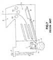
- FIG. 6is a front view of a gate plate 2 , showing the main parts of a coin sorting device equipped with a conventional coin pullout prevention lever.
- This gate plate 2constitutes one side wall 4 a of a coin guiding passage 4 for guiding coins that have been inserted into coin insertion port 3 towards the left in the drawing.
- the gate plate 2which can freely be opened and closed, covers the upper portion of a main plate (not shown in the drawings), which is part of the main body of the coin sorting device, and arranged in opposition to the gate plate 2 .
- the gate plate 2is hinged on a shaft 5 and it can be opened and closed with respect to the main plate (not shown in the drawings) arranged in opposition to its main surface, so that when coins are stuck in the coin guiding passage 4 , the coin guiding passage can be opened, and the stuck coins can be removed.
- a coin pullout prevention lever 1is arranged downstream of the coin guiding passage 4 , so as to effectively prevent mischievous pulling out of inserted coins by force with some means such as a string.
- This coin pullout prevention lever 1is one lever that is rotatably supported by a shaft (not shown in the drawings) on the rear surface of the gate plate 2 , and in its initial position, its tip 1 a protrudes due to its own weight towards the main plate (not shown in the drawings), which is arranged in opposition to the front surface of the gate plate 2 .
- a pass sensor 6 for detecting coins falling down from the downstream of the coin guiding passage 4is arranged in the main plate positioned below the coin pullout prevention lever 1 .
- the coinis regarded as a deposit in the coin sorting device.
- Numeral 7 in FIG. 6is a coin discrimination device, for discriminating the inserted coins into genuine and counterfeit, and for classifying them according to denominations.
- This coin discrimination device 7includes an oscillation coil and a receiving coil arranged in opposition to one another at a certain interval.
- One of the oscillation coil and the receiving coilis arranged on the rear surface of the gate plate 2 , and the other one is arranged on the rear surface of the main plate (not shown in the drawings) at a position opposing the gate plate 2 .
- numeral 8is a gate rail arranged below the coin insertion port 3
- numeral 9is a guide rail, which makes up the bottom of the coin passage 4
- numeral 10denotes concave positioning members formed along an advance direction of the coin passage 4 , which decrease the areal contact with the inserted coin, and smoothly guide the coin.
- Numeral 60 in FIG. 6denotes liquid discharge holes for discharging liquids (such as water) that have been introduced through the coin insertion port 3 .
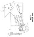
- this coin pullout prevention lever 1when an inserted coin A, to which a string 11 has been tied, rolls down the coin guiding passage 4 , falls down from the downstream edge of the coin guiding passage 4 , and is detected by the pass sensor 6 as shown in FIG. 7, and if anyone tries to pull the coin A back out again with the string 11 , as shown in FIG. 8, the coin A engages with a tip rear face 1 b of the coin pullout prevention lever 1 , so that it can be prevented from being pulled back out.
- the coin Bwhose insertion has been confirmed by the pass sensor 6 , still pushes the tip 1 a of the coin pullout prevention lever 1 towards the gate plate 2 , and therefore the coin B does not engage the tip rear face 1 b of the coin pullout prevention lever 1 . Consequently, if in this situation the coin B is pulled up again with a string 11 , there is the problem that the coin B can be pulled back out through the con insertion port 3 .
- the distance L′ from the lower edge 1 a of the coin pullout prevention lever 1 to the pass sensor 6is set to be larger than the diameter of the larger coin B, as shown in FIG. 11, then the entire coin B will have moved completely downward from the tip 1 a of the coin pullout prevention lever 1 when its insertion is being confirmed by the pass sensor 6 .
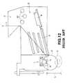
- the coin Bengages the tip rear face 1 b of the coin pullout prevention lever 1 as shown in FIG. 12, and its backflow is prevented, thereby preventing the pullout of the coin B.
- a coin pullout prevention lever of the present inventionis provided with, around one coin pullout prevention lever, another coin pullout prevention lever with tip position thereof being different from that of the one coin pullout prevention lever is arranged.
- FIG. 1is a front view of a gate plate showing a coin pullout prevention lever in accordance with the present invention
- FIG. 2is a front view of a gate plate showing the operation of a coin pullout prevention lever in accordance with the present invention
- FIG. 3is a front view of a gate plate showing the operation of a coin pullout prevention lever in accordance with the present invention
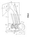
- FIG. 4is a front view of a gate plate showing the operation of a coin pullout prevention lever in accordance with the present invention
- FIG. 5is a front view of a gate plate showing the operation of a coin pullout prevention lever in accordance with the present invention
- FIG. 6is a front view of a gate plate showing a conventional coin pullout prevention lever
- FIG. 7is a front view of a gate plate showing the operation of the conventional coin pullout prevention lever
- FIG. 8is a front view of a gate plate showing the operation of the conventional coin pullout prevention lever
- FIG. 9is a front view of a gate plate showing the operation of the conventional coin pullout prevention lever
- FIG. 10is a front view of a gate plate showing the operation of the conventional coin pullout prevention lever
- FIG. 11is a front view of a gate plate showing the operation of the conventional coin pullout prevention lever.
- FIG. 12is a front view of a gate plate showing the operation of the conventional coin pullout prevention lever.
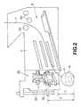
- FIG. 1is a front view of a gate plate 2 provided with a coin pullout prevention lever 20 in accordance with the present invention. Elements identical to the ones in FIG. 6 are denoted by the same numerals.
- the coin pullout prevention lever 20includes a first coin pullout prevention lever 30 arranged downstream from a coin guiding path 4 , and a second coin pullout prevention lever 40 arranged above the first coin pullout prevention lever 30 .
- the cross-section of the first coin pullout prevention lever 30is substantially U-shaped, and the shafts 33 and 34 protrude from the end portions of its sides 31 and 32 .
- the shafts 33 and 34are fitted in and supported by corresponding bearing portions 35 and 36 , which are concave portions formed in the gate plate 2 , so that the first coin pullout prevention lever 30 is supported in a manner that it can swing freely around the shafts 33 and 34 towards a main plate (not shown in the drawings) of the coin sorting device, which is arranged in opposition to the front surface of the gate plate 2 .
- An oblique face 38is formed in a surface of the tip 37 of the first coin pullout prevention lever 30 that faces the upstream side of the coin guiding path 4 , so that when a coin rolling down the coin guiding path 4 hits this lever tip 37 , the lever tip 37 is pushed towards the gate plate 2 and the coin falls smoothly downward.
- the second coin pullout prevention lever 40which is arranged above the first coin pullout prevention lever 30 , also has a substantially U-shaped cross-section like the first coin pullout prevention lever 30 , the shafts 43 and 44 protrude from end portions of its sides 41 and 42 , and the shafts 43 and 44 are fitted in and supported by corresponding bearing portions 45 and 46 at corresponding positions, which are formed in the gate plate 2 .
- the second coin pullout prevention lever 40is also supported in a manner that it can swing freely around the shafts 43 and 44 towards a main plate (not shown in the drawings) of the coin sorting device, which is arranged in opposition to the main surface of the gate plate 2 . And, in its initial position, a tip 47 of the second coin pullout prevention lever 40 protrudes towards the opposing main plate, due to its own weight.
- an oblique face 48is formed in a surface of the tip 47 of the second coin pullout prevention lever 40 that faces the upstream side of the coin guiding path 4 , so that when a coin rolling down the coin guiding path 4 hits this lever tip 47 , the lever tip 47 is pushed towards the gate plate 2 and the inserted coin falls smoothly downward.
- the distance between the tip 37 of the first coin pullout prevention lever 30 and a pass sensor 6is set to L
- the distance between the tip 47 of the second coin pullout prevention lever 40 and a pass sensor 6is set to L′ (with L′>L).
- the first coin pullout prevention lever 30When the first coin pullout prevention lever 30 is engaged by the coin A, it rotates clockwise around the shafts 33 and 34 , but this rotation is blocked when the tip 37 of the first coin pullout prevention lever 30 abuts the main plate (not shown in the drawings) arranged on the front surface of the gate plate 2 .
- the second coin pullout prevention lever 40when the second coin pullout prevention lever 40 is engaged by the coin B, it rotates clockwise around the aforementioned shafts 43 and 44 , but this rotation is blocked when the tip 47 of the second coin pullout prevention lever 40 abuts the main plate (not shown in the drawings) arranged on the front surface of the gate plate 2 .
- This embodimenthas been explained only for the case that one separate second coin pullout prevention lever 40 is arranged above the first coin pullout prevention lever 30 .
- the present inventionis not limited to this embodiment, and it is also possible to arranged one or more second coin pullout prevention levers 40 at different positions. As long as the tips of the coin pullout prevention levers are arranged at different positions, there is no limitation of their number and positional arrangement relative to the first coin pullout prevention lever to the above-described embodiment.
- one coin pullout prevention leveris arranged near another coin pullout prevention lever whose tip position is different, so that the pulling out of coins of different diameters can be prevented reliably.
- the pulling out of coins of various diameterscan be prevented without changing the position of the pass sensor. This eliminates the need to manufacture different types of coin sorting devices with pass sensors being arranged at different positions according to the diameters of the coins whose pulling out is to be prevented. Since the common coin sorting device can be used, a considerable reduction of cost for the manufacture of the coin sorting device becomes possible.
- the present inventionis suitable for a coin pullout prevention lever that prevents the pulling out of coins with various diameters without altering the basic design of a coin sorting device.
Landscapes
- Physics & Mathematics (AREA)
- General Physics & Mathematics (AREA)
- Testing Of Coins (AREA)
- Slot Machines And Peripheral Devices (AREA)
Abstract
Description
Claims (4)
Applications Claiming Priority (2)
| Application Number | Priority Date | Filing Date | Title |
|---|---|---|---|
| JP11-064896 | 1999-03-11 | ||
| JP06489699AJP3997031B2 (en) | 1999-03-11 | 1999-03-11 | Coin withdrawal lever for coin sorter |
Publications (1)
| Publication Number | Publication Date |
|---|---|
| US6193045B1true US6193045B1 (en) | 2001-02-27 |
Family
ID=13271310
Family Applications (1)
| Application Number | Title | Priority Date | Filing Date |
|---|---|---|---|
| US09/524,068Expired - Fee RelatedUS6193045B1 (en) | 1999-03-11 | 2000-03-13 | Coin pullout prevention lever of coin sorting device |
Country Status (3)
| Country | Link |
|---|---|
| US (1) | US6193045B1 (en) |
| JP (1) | JP3997031B2 (en) |
| KR (1) | KR100334171B1 (en) |
Cited By (14)
| Publication number | Priority date | Publication date | Assignee | Title |
|---|---|---|---|---|
| US6425471B1 (en)* | 1999-08-18 | 2002-07-30 | Jofemar, S.A. | Coin selector |
| US20080011578A1 (en)* | 2006-07-12 | 2008-01-17 | Hiroshi Abe | Coin selector |
| US20090218191A1 (en)* | 2008-02-28 | 2009-09-03 | International Currency Technologies Corporation | Cash receiver for consumption system |
| US20140174880A1 (en)* | 2012-12-20 | 2014-06-26 | J.J. Mackay Canada Limited | Anti-fishing device for a coin chute |
| US9230385B1 (en)* | 2012-12-18 | 2016-01-05 | Imonex Services, Inc. | Coin acceptor with anti-fraud feature |
| US9406056B2 (en) | 2011-03-03 | 2016-08-02 | J.J. Mackay Canada Limited | Parking meter with contactless payment |
| US9494922B2 (en) | 2008-12-23 | 2016-11-15 | J.J. Mackay Canada Limited | Single space wireless parking with improved antenna placements |
| US9652921B2 (en)* | 2015-06-16 | 2017-05-16 | J.J. Mackay Canada Limited | Coin chute with anti-fishing assembly |
| USD863074S1 (en) | 2015-10-16 | 2019-10-15 | J. J. Mackay Canada Limited | Parking meter |
| USRE48566E1 (en) | 2015-07-15 | 2021-05-25 | J.J. Mackay Canada Limited | Parking meter |
| US11762479B2 (en) | 2019-01-30 | 2023-09-19 | J.J. Mackay Canada Limited | SPI keyboard module for a parking meter and a parking meter having an SPI keyboard module |
| US11922756B2 (en) | 2019-01-30 | 2024-03-05 | J.J. Mackay Canada Limited | Parking meter having touchscreen display |
| US11972654B2 (en) | 2015-08-11 | 2024-04-30 | J.J. Mackay Canada Limited | Lightweight vandal resistant parking meter |
| US12417669B2 (en) | 2015-08-08 | 2025-09-16 | J.J. Mackay Canada Limited | Lighweight vandal resistent parking meter |
Citations (4)
| Publication number | Priority date | Publication date | Assignee | Title |
|---|---|---|---|---|
| US4243133A (en)* | 1979-03-08 | 1981-01-06 | Bally Manufacturing Corporation | Anti-stringing device for a coin detecting device |
| US4327824A (en)* | 1980-06-04 | 1982-05-04 | Coin Mechanisms, Inc. | Cheat preventing device for coin machines |
| US5007079A (en)* | 1989-09-15 | 1991-04-09 | International Teleservice Corporation | Coin fraud prevention unit and modular configurations for pay telephone stations |
| US5769200A (en)* | 1995-08-09 | 1998-06-23 | National Rejectors, Inc., Gmbh | Coin collection apparatus |
- 1999
- 1999-03-11JPJP06489699Apatent/JP3997031B2/ennot_activeExpired - Fee Related
- 2000
- 2000-03-08KRKR1020000011417Apatent/KR100334171B1/ennot_activeExpired - Fee Related
- 2000-03-13USUS09/524,068patent/US6193045B1/ennot_activeExpired - Fee Related
Patent Citations (4)
| Publication number | Priority date | Publication date | Assignee | Title |
|---|---|---|---|---|
| US4243133A (en)* | 1979-03-08 | 1981-01-06 | Bally Manufacturing Corporation | Anti-stringing device for a coin detecting device |
| US4327824A (en)* | 1980-06-04 | 1982-05-04 | Coin Mechanisms, Inc. | Cheat preventing device for coin machines |
| US5007079A (en)* | 1989-09-15 | 1991-04-09 | International Teleservice Corporation | Coin fraud prevention unit and modular configurations for pay telephone stations |
| US5769200A (en)* | 1995-08-09 | 1998-06-23 | National Rejectors, Inc., Gmbh | Coin collection apparatus |
Cited By (35)
| Publication number | Priority date | Publication date | Assignee | Title |
|---|---|---|---|---|
| AU772606B2 (en)* | 1999-08-18 | 2004-05-06 | Jofemar, S.A. | Improved coin selector |
| US6425471B1 (en)* | 1999-08-18 | 2002-07-30 | Jofemar, S.A. | Coin selector |
| US20080011578A1 (en)* | 2006-07-12 | 2008-01-17 | Hiroshi Abe | Coin selector |
| US7661521B2 (en)* | 2006-07-12 | 2010-02-16 | Asahi Seiko Company Ltd. | Coin selector |
| US20090218191A1 (en)* | 2008-02-28 | 2009-09-03 | International Currency Technologies Corporation | Cash receiver for consumption system |
| US10141629B2 (en) | 2008-12-23 | 2018-11-27 | J.J. Mackay Canada Limited | Single space wireless parking with improved antenna placements |
| US10998612B2 (en) | 2008-12-23 | 2021-05-04 | J.J. Mackay Canada Limited | Single space wireless parking with improved antenna placements |
| US10573953B2 (en) | 2008-12-23 | 2020-02-25 | J.J. Mackay Canada Limited | Single space wireless parking with improved antenna placements |
| US11670835B2 (en) | 2008-12-23 | 2023-06-06 | J.J Mackay Canada Limited | Single space wireless parking with improved antenna placements |
| US9494922B2 (en) | 2008-12-23 | 2016-11-15 | J.J. Mackay Canada Limited | Single space wireless parking with improved antenna placements |
| US12368227B2 (en) | 2008-12-23 | 2025-07-22 | J.J. Mackay Canada Limited | Single space wireless parking with improved antenna placements |
| US12008856B2 (en) | 2011-03-03 | 2024-06-11 | J.J. Mackay Canada Limited | Single space parking meter and removable single space parking meter mechanism |
| US9934645B2 (en) | 2011-03-03 | 2018-04-03 | J.J. Mackay Canada Limited | Parking meter with contactless payment |
| US9842455B2 (en) | 2011-03-03 | 2017-12-12 | J.J. Mackay Canada Limited | Single space parking meter and removable single space parking meter mechanism |
| US10192388B2 (en) | 2011-03-03 | 2019-01-29 | J.J. Mackay Canada Limited | Single space parking meter and removable single space parking meter mechanism |
| US10424147B2 (en) | 2011-03-03 | 2019-09-24 | J.J. Mackay Canada Limited | Parking meter with contactless payment |
| US12430978B2 (en) | 2011-03-03 | 2025-09-30 | J.J. Mackay Canada Limited | Parking meter with contactless payment |
| US9443236B2 (en) | 2011-03-03 | 2016-09-13 | J.J. Mackay Canada Limited | Single space parking meter and removable single space parking meter mechanism |
| US11699321B2 (en) | 2011-03-03 | 2023-07-11 | J.J Mackay Canada Limited | Parking meter with contactless payment |
| US9406056B2 (en) | 2011-03-03 | 2016-08-02 | J.J. Mackay Canada Limited | Parking meter with contactless payment |
| US10861278B2 (en) | 2011-03-03 | 2020-12-08 | J.J. Mackay Canada Limited | Parking meter with contactless payment |
| US9230385B1 (en)* | 2012-12-18 | 2016-01-05 | Imonex Services, Inc. | Coin acceptor with anti-fraud feature |
| US20140174880A1 (en)* | 2012-12-20 | 2014-06-26 | J.J. Mackay Canada Limited | Anti-fishing device for a coin chute |
| US9652921B2 (en)* | 2015-06-16 | 2017-05-16 | J.J. Mackay Canada Limited | Coin chute with anti-fishing assembly |
| USRE48566E1 (en) | 2015-07-15 | 2021-05-25 | J.J. Mackay Canada Limited | Parking meter |
| US12417669B2 (en) | 2015-08-08 | 2025-09-16 | J.J. Mackay Canada Limited | Lighweight vandal resistent parking meter |
| US11972654B2 (en) | 2015-08-11 | 2024-04-30 | J.J. Mackay Canada Limited | Lightweight vandal resistant parking meter |
| US11978300B2 (en) | 2015-08-11 | 2024-05-07 | J.J. Mackay Canada Limited | Single space parking meter |
| USD863988S1 (en) | 2015-10-16 | 2019-10-22 | J.J. Mackay Canada Limited | Parking meter |
| USD863987S1 (en) | 2015-10-16 | 2019-10-22 | J.J. Mackay Canada Limited | Parking meter |
| USD863075S1 (en) | 2015-10-16 | 2019-10-15 | J.J. Mackay Canada Limited | Parking meter |
| USD863076S1 (en) | 2015-10-16 | 2019-10-15 | J. J. Mackay Canada Limited | Parking meter |
| USD863074S1 (en) | 2015-10-16 | 2019-10-15 | J. J. Mackay Canada Limited | Parking meter |
| US11762479B2 (en) | 2019-01-30 | 2023-09-19 | J.J. Mackay Canada Limited | SPI keyboard module for a parking meter and a parking meter having an SPI keyboard module |
| US11922756B2 (en) | 2019-01-30 | 2024-03-05 | J.J. Mackay Canada Limited | Parking meter having touchscreen display |
Also Published As
| Publication number | Publication date |
|---|---|
| KR20000062774A (en) | 2000-10-25 |
| JP2000259896A (en) | 2000-09-22 |
| KR100334171B1 (en) | 2002-04-25 |
| JP3997031B2 (en) | 2007-10-24 |
Similar Documents
| Publication | Publication Date | Title |
|---|---|---|
| US6193045B1 (en) | Coin pullout prevention lever of coin sorting device | |
| CN101105872B (en) | coin selector | |
| JP5109035B2 (en) | Coin feeding device | |
| JP2008117025A5 (en) | ||
| US6695689B2 (en) | Detector unit for coin blockage in a coin dispenser | |
| JP5486644B2 (en) | Coin deposit / withdrawal device | |
| US5054056A (en) | Tamper-deterrent device | |
| JP2958723B2 (en) | Coin processing equipment | |
| AU733542B2 (en) | Coin guide device | |
| JP2008148728A (en) | Cast token sorter and game machine | |
| JP2583106B2 (en) | Coin sorting equipment | |
| JP2007206767A (en) | Foreign substance return mechanism, and automatic transaction device | |
| US5813509A (en) | Coin gate | |
| US6283267B1 (en) | Coin selector assembly | |
| JP3506318B2 (en) | Coin sorting device | |
| US9230385B1 (en) | Coin acceptor with anti-fraud feature | |
| JP2000093636A (en) | Game media dispenser | |
| JP2588657Y2 (en) | Coin sorting equipment | |
| JP6565200B2 (en) | Medal sorting device | |
| JP4132639B2 (en) | Coin sorting machine | |
| JP4132612B2 (en) | Coin sorting machine | |
| JPH09237373A (en) | Coin sorter | |
| JPH09237374A (en) | Coin sorter | |
| JP2004021808A (en) | Vending machine change return | |
| JPH03226895A (en) | banknote identification device |
Legal Events
| Date | Code | Title | Description |
|---|---|---|---|
| AS | Assignment | Owner name:KABUSHIKI KAISHA NIPPON CONLUX, JAPAN Free format text:ASSIGNMENT OF ASSIGNORS INTEREST;ASSIGNORS:ISHIDA, TAKESHI;YAMADA, JUN;YAGI, MASATO;REEL/FRAME:010673/0295 Effective date:20000208 | |
| FPAY | Fee payment | Year of fee payment:4 | |
| AS | Assignment | Owner name:CITIBANK, N.A., TOKYO BRANCH, JAPAN Free format text:SECURITY AGREEMENT;ASSIGNOR:NIPPON CONLUX CO., LTD.;REEL/FRAME:017957/0752 Effective date:20060719 | |
| AS | Assignment | Owner name:NIPPON CONLUX CO., LTD., JAPAN Free format text:CHANGE OF NAME;ASSIGNOR:AP6 CO., LTD.;REEL/FRAME:018679/0787 Effective date:20060930 Owner name:AP6 CO., LTD., JAPAN Free format text:MERGER;ASSIGNOR:NIPPON CONLUX CO., LTD.;REEL/FRAME:018679/0741 Effective date:20060930 | |
| AS | Assignment | Owner name:CITIBANK JAPAN LTD., JAPAN Free format text:CHANGE OF SECURITY AGENT;ASSIGNOR:CITIBANK, N.A., TOKYO BUILDING;REEL/FRAME:019704/0952 Effective date:20070701 | |
| FEPP | Fee payment procedure | Free format text:PAYER NUMBER DE-ASSIGNED (ORIGINAL EVENT CODE: RMPN); ENTITY STATUS OF PATENT OWNER: LARGE ENTITY Free format text:PAYOR NUMBER ASSIGNED (ORIGINAL EVENT CODE: ASPN); ENTITY STATUS OF PATENT OWNER: LARGE ENTITY | |
| FPAY | Fee payment | Year of fee payment:8 | |
| REMI | Maintenance fee reminder mailed | ||
| LAPS | Lapse for failure to pay maintenance fees | ||
| STCH | Information on status: patent discontinuation | Free format text:PATENT EXPIRED DUE TO NONPAYMENT OF MAINTENANCE FEES UNDER 37 CFR 1.362 | |
| FP | Lapsed due to failure to pay maintenance fee | Effective date:20130227 |