US6192922B1 - Airflow control valve for a clean room - Google Patents
Airflow control valve for a clean roomDownload PDFInfo
- Publication number
- US6192922B1 US6192922B1US09/323,591US32359199AUS6192922B1US 6192922 B1US6192922 B1US 6192922B1US 32359199 AUS32359199 AUS 32359199AUS 6192922 B1US6192922 B1US 6192922B1
- Authority
- US
- United States
- Prior art keywords
- airflow
- damper
- duct
- plates
- plate
- Prior art date
- Legal status (The legal status is an assumption and is not a legal conclusion. Google has not performed a legal analysis and makes no representation as to the accuracy of the status listed.)
- Expired - Fee Related
Links
- 239000000126substanceSubstances0.000claimsdescription17
- 238000005259measurementMethods0.000claimsdescription5
- 230000008859changeEffects0.000claimsdescription3
- 238000004891communicationMethods0.000claimsdescription3
- 230000004044responseEffects0.000claimsdescription3
- 230000008878couplingEffects0.000abstractdescription5
- 238000010168coupling processMethods0.000abstractdescription5
- 238000005859coupling reactionMethods0.000abstractdescription5
- 238000004519manufacturing processMethods0.000description21
- 238000000034methodMethods0.000description15
- 230000008569processEffects0.000description10
- 239000007787solidSubstances0.000description10
- 230000000712assemblyEffects0.000description8
- 238000000429assemblyMethods0.000description8
- 230000000694effectsEffects0.000description6
- XUIMIQQOPSSXEZ-UHFFFAOYSA-NSiliconChemical compound[Si]XUIMIQQOPSSXEZ-UHFFFAOYSA-N0.000description5
- 239000003517fumeSubstances0.000description5
- 229910052710siliconInorganic materials0.000description5
- 239000010703siliconSubstances0.000description5
- 235000012431wafersNutrition0.000description5
- 238000012544monitoring processMethods0.000description4
- 230000001276controlling effectEffects0.000description3
- 230000003247decreasing effectEffects0.000description3
- 238000013461designMethods0.000description3
- 238000011378penetrating methodMethods0.000description3
- NBIIXXVUZAFLBC-UHFFFAOYSA-NPhosphoric acidChemical compoundOP(O)(O)=ONBIIXXVUZAFLBC-UHFFFAOYSA-N0.000description2
- 230000002411adverseEffects0.000description2
- 239000007789gasSubstances0.000description2
- 231100001261hazardousToxicity0.000description2
- 238000009434installationMethods0.000description2
- 230000003993interactionEffects0.000description2
- 230000007246mechanismEffects0.000description2
- 239000004065semiconductorSubstances0.000description2
- 238000012935AveragingMethods0.000description1
- 229920001780ECTFEPolymers0.000description1
- 239000004743PolypropyleneSubstances0.000description1
- 239000004809TeflonSubstances0.000description1
- 229920006362Teflon®Polymers0.000description1
- 230000002378acidificating effectEffects0.000description1
- 230000004913activationEffects0.000description1
- 238000004378air conditioningMethods0.000description1
- 229910000147aluminium phosphateInorganic materials0.000description1
- 238000013459approachMethods0.000description1
- 238000009530blood pressure measurementMethods0.000description1
- 230000003749cleanlinessEffects0.000description1
- 230000007613environmental effectEffects0.000description1
- 238000010438heat treatmentMethods0.000description1
- 238000012423maintenanceMethods0.000description1
- 239000000463materialSubstances0.000description1
- 230000013011matingEffects0.000description1
- 238000012986modificationMethods0.000description1
- 230000004048modificationEffects0.000description1
- 230000001473noxious effectEffects0.000description1
- 230000035515penetrationEffects0.000description1
- -1polypropylenePolymers0.000description1
- 229920001155polypropylenePolymers0.000description1
- 238000012545processingMethods0.000description1
- 230000001105regulatory effectEffects0.000description1
- 238000009420retrofittingMethods0.000description1
- 238000000926separation methodMethods0.000description1
- 238000004513sizingMethods0.000description1
- 229910001220stainless steelInorganic materials0.000description1
- 239000010935stainless steelSubstances0.000description1
- BFKJFAAPBSQJPD-UHFFFAOYSA-NtetrafluoroetheneChemical compoundFC(F)=C(F)FBFKJFAAPBSQJPD-UHFFFAOYSA-N0.000description1
- 238000011144upstream manufacturingMethods0.000description1
- 238000009423ventilationMethods0.000description1
Images


Classifications
- F—MECHANICAL ENGINEERING; LIGHTING; HEATING; WEAPONS; BLASTING
- F16—ENGINEERING ELEMENTS AND UNITS; GENERAL MEASURES FOR PRODUCING AND MAINTAINING EFFECTIVE FUNCTIONING OF MACHINES OR INSTALLATIONS; THERMAL INSULATION IN GENERAL
- F16K—VALVES; TAPS; COCKS; ACTUATING-FLOATS; DEVICES FOR VENTING OR AERATING
- F16K3/00—Gate valves or sliding valves, i.e. cut-off apparatus with closing members having a sliding movement along the seat for opening and closing
- F16K3/02—Gate valves or sliding valves, i.e. cut-off apparatus with closing members having a sliding movement along the seat for opening and closing with flat sealing faces; Packings therefor
- F16K3/04—Gate valves or sliding valves, i.e. cut-off apparatus with closing members having a sliding movement along the seat for opening and closing with flat sealing faces; Packings therefor with pivoted closure members
- F16K3/06—Gate valves or sliding valves, i.e. cut-off apparatus with closing members having a sliding movement along the seat for opening and closing with flat sealing faces; Packings therefor with pivoted closure members in the form of closure plates arranged between supply and discharge passages
- F16K3/08—Gate valves or sliding valves, i.e. cut-off apparatus with closing members having a sliding movement along the seat for opening and closing with flat sealing faces; Packings therefor with pivoted closure members in the form of closure plates arranged between supply and discharge passages with circular plates rotatable around their centres
- F16K3/085—Gate valves or sliding valves, i.e. cut-off apparatus with closing members having a sliding movement along the seat for opening and closing with flat sealing faces; Packings therefor with pivoted closure members in the form of closure plates arranged between supply and discharge passages with circular plates rotatable around their centres the axis of supply passage and the axis of discharge passage being coaxial and parallel to the axis of rotation of the plates
- F—MECHANICAL ENGINEERING; LIGHTING; HEATING; WEAPONS; BLASTING
- F24—HEATING; RANGES; VENTILATING
- F24F—AIR-CONDITIONING; AIR-HUMIDIFICATION; VENTILATION; USE OF AIR CURRENTS FOR SCREENING
- F24F3/00—Air-conditioning systems in which conditioned primary air is supplied from one or more central stations to distributing units in the rooms or spaces where it may receive secondary treatment; Apparatus specially designed for such systems
- F24F3/12—Air-conditioning systems in which conditioned primary air is supplied from one or more central stations to distributing units in the rooms or spaces where it may receive secondary treatment; Apparatus specially designed for such systems characterised by the treatment of the air otherwise than by heating and cooling
- F24F3/16—Air-conditioning systems in which conditioned primary air is supplied from one or more central stations to distributing units in the rooms or spaces where it may receive secondary treatment; Apparatus specially designed for such systems characterised by the treatment of the air otherwise than by heating and cooling by purification, e.g. by filtering; by sterilisation; by ozonisation
- F24F3/167—Clean rooms, i.e. enclosed spaces in which a uniform flow of filtered air is distributed
- G—PHYSICS
- G05—CONTROLLING; REGULATING
- G05D—SYSTEMS FOR CONTROLLING OR REGULATING NON-ELECTRIC VARIABLES
- G05D7/00—Control of flow
- G05D7/06—Control of flow characterised by the use of electric means
- G05D7/0617—Control of flow characterised by the use of electric means specially adapted for fluid materials
- G05D7/0629—Control of flow characterised by the use of electric means specially adapted for fluid materials characterised by the type of regulator means
- G05D7/0635—Control of flow characterised by the use of electric means specially adapted for fluid materials characterised by the type of regulator means by action on throttling means
- F—MECHANICAL ENGINEERING; LIGHTING; HEATING; WEAPONS; BLASTING
- F24—HEATING; RANGES; VENTILATING
- F24F—AIR-CONDITIONING; AIR-HUMIDIFICATION; VENTILATION; USE OF AIR CURRENTS FOR SCREENING
- F24F13/00—Details common to, or for air-conditioning, air-humidification, ventilation or use of air currents for screening
- F24F13/08—Air-flow control members, e.g. louvres, grilles, flaps or guide plates
- F24F13/10—Air-flow control members, e.g. louvres, grilles, flaps or guide plates movable, e.g. dampers
- F24F13/14—Air-flow control members, e.g. louvres, grilles, flaps or guide plates movable, e.g. dampers built up of tilting members, e.g. louvre
- F24F13/1426—Air-flow control members, e.g. louvres, grilles, flaps or guide plates movable, e.g. dampers built up of tilting members, e.g. louvre characterised by actuating means
- F24F2013/148—Air-flow control members, e.g. louvres, grilles, flaps or guide plates movable, e.g. dampers built up of tilting members, e.g. louvre characterised by actuating means with magnets
- F—MECHANICAL ENGINEERING; LIGHTING; HEATING; WEAPONS; BLASTING
- F24—HEATING; RANGES; VENTILATING
- F24F—AIR-CONDITIONING; AIR-HUMIDIFICATION; VENTILATION; USE OF AIR CURRENTS FOR SCREENING
- F24F2110/00—Control inputs relating to air properties
- F24F2110/30—Velocity
- Y—GENERAL TAGGING OF NEW TECHNOLOGICAL DEVELOPMENTS; GENERAL TAGGING OF CROSS-SECTIONAL TECHNOLOGIES SPANNING OVER SEVERAL SECTIONS OF THE IPC; TECHNICAL SUBJECTS COVERED BY FORMER USPC CROSS-REFERENCE ART COLLECTIONS [XRACs] AND DIGESTS
- Y10—TECHNICAL SUBJECTS COVERED BY FORMER USPC
- Y10T—TECHNICAL SUBJECTS COVERED BY FORMER US CLASSIFICATION
- Y10T137/00—Fluid handling
- Y10T137/7722—Line condition change responsive valves
- Y10T137/7758—Pilot or servo controlled
- Y10T137/7759—Responsive to change in rate of fluid flow
- Y—GENERAL TAGGING OF NEW TECHNOLOGICAL DEVELOPMENTS; GENERAL TAGGING OF CROSS-SECTIONAL TECHNOLOGIES SPANNING OVER SEVERAL SECTIONS OF THE IPC; TECHNICAL SUBJECTS COVERED BY FORMER USPC CROSS-REFERENCE ART COLLECTIONS [XRACs] AND DIGESTS
- Y10—TECHNICAL SUBJECTS COVERED BY FORMER USPC
- Y10T—TECHNICAL SUBJECTS COVERED BY FORMER US CLASSIFICATION
- Y10T137/00—Fluid handling
- Y10T137/8593—Systems
- Y10T137/86493—Multi-way valve unit
- Y10T137/86718—Dividing into parallel flow paths with recombining
- Y10T137/86743—Rotary
- Y—GENERAL TAGGING OF NEW TECHNOLOGICAL DEVELOPMENTS; GENERAL TAGGING OF CROSS-SECTIONAL TECHNOLOGIES SPANNING OVER SEVERAL SECTIONS OF THE IPC; TECHNICAL SUBJECTS COVERED BY FORMER USPC CROSS-REFERENCE ART COLLECTIONS [XRACs] AND DIGESTS
- Y10—TECHNICAL SUBJECTS COVERED BY FORMER USPC
- Y10T—TECHNICAL SUBJECTS COVERED BY FORMER US CLASSIFICATION
- Y10T137/00—Fluid handling
- Y10T137/8593—Systems
- Y10T137/86928—Sequentially progressive opening or closing of plural valves
- Y10T137/87016—Lost motion
- Y10T137/87032—Rotary concentric valves
- Y—GENERAL TAGGING OF NEW TECHNOLOGICAL DEVELOPMENTS; GENERAL TAGGING OF CROSS-SECTIONAL TECHNOLOGIES SPANNING OVER SEVERAL SECTIONS OF THE IPC; TECHNICAL SUBJECTS COVERED BY FORMER USPC CROSS-REFERENCE ART COLLECTIONS [XRACs] AND DIGESTS
- Y10—TECHNICAL SUBJECTS COVERED BY FORMER USPC
- Y10T—TECHNICAL SUBJECTS COVERED BY FORMER US CLASSIFICATION
- Y10T137/00—Fluid handling
- Y10T137/8593—Systems
- Y10T137/86928—Sequentially progressive opening or closing of plural valves
- Y10T137/87016—Lost motion
- Y10T137/8704—First valve actuates second valve
Definitions
- the invention described in this documentgenerally relates to controlling the airflow into clean rooms and small clean room enclosures (“minienvironments”) of the sort used in silicon wafer manufacturing. More specifically, the invention relates to airflow control valves or dampers for controlling, maintaining and monitoring the flow of air through manufacturing environments such as clean rooms and minienvironments that require precise control of airflow and exhaust.
- HVACheating, ventilating, and air conditioning
- damperslocated at various points within ducts in the HVAC system. These dampers may be, for example, gate valves, butterfly valves, or blast valves, and may be fixed, adjustable or motorized. By increasing or decreasing the amount of airflow resistance or dampening, the airflow can be decreased or increased, respectively, in a particular region.
- Minienvironmentsare used to house many of the process tool operations that are used in the silicon wafer and semiconductor integrated-circuit chip manufacturing industries.
- the typical minienvironmenthas two fundamental purposes. First, it provides the ability to maintain an extremely clean manufacturing space. Second, it provides containment and control of chemical vapors that are generated in many wafer-manufacturing and chip-manufacturing operations. It is well known that the delivery and control of the airflow through the minienvironment impacts both cleanliness and chemical containment.
- the volumetric airflow though a minienvironmentbe controlled and maintained at a precise and continuous rate because 1) fluctuations in the airflow or exhaust can adversely affect the product being manufactured, and 2) the manufacturing process often involves the use of chemicals that produce hazardous fumes that must be ventilated to ensure the safety of operators and avoid damage to related machinery and systems.
- the amount of airflowshould optimally not vary by more than +/ ⁇ 5 percent from a set-point.
- the typical approach to regulating airflowuses dampers such as gate valves, butterfly valves, or blast valves in HVAC systems at the respective locations where the airflow is supplied to and exhausted from the minienvironment.
- the typical minienvironmentis configured as shown in the FIG. 1 schematic.
- Supply airis supplied into the minienvironment by a fan-filter unit.
- the fan in the moduledrives air through a suitable filter and then into the process area within the minienvironment.
- the airis exhausted through an exhaust duct to a scrubber (air may also be exhausted through other openings in the minienvironment).
- the exhaust ductmay also have an adjustable damper.
- airis not only driven through the minienvironment by the fan-filter unit, but also drawn from the minienvironment by a downstream exhaust fan. Both of these components affect the overall airflow in the minienvironment and must be adjusted relative to each other to obtain a desired equilibrium.
- a wet benchis another example of a manufacturing application requiring precise control of airflow.
- a wet benchis a minienvironment process tool that is used to chemically clean silicon wafers.
- the second scenario in a wet benchinvolves a “hot” tank containing chemicals (typically phosphoric acid) that are maintained at a temperature above 160 degrees Celsius.
- desired airflowis achieved by first adjusting the exhaust damper to 400 cfm followed by setting the fan filter speed to create the same range of positive pressure inside the minienvironment (i.e., less than 0.001 in. w.g. but greater than 0.0002 in. w.g.).
- the exhaust flow rateis then checked against the desired flow rate, and the process repeated if necessary. It should be understood that these settings are typical.
- One problem with maintaining accurate airflow in systemsis in balancing the airflow through different regions.
- the airflow in such a systemis balanced by first adjusting the exhaust flow via the damper, and then adjusting the fan speed in the fan-filter unit until a slightly positive pressure is created inside the minienvironment.
- the balancing processtypically requires repeatedly readjusting the dampers and fan speed in sequence until the flow rate reaches an equilibrium that is within an acceptable range.
- Such a balancing methodis time consuming, tedious, prone to inaccurate settings, and not responsive to external changes in the airflow supply system.
- the entire HVAC systemis still subject to changes in supply or exhaust pressure and to changes in the demand requirements of various components of the HVAC system, any of which could require having to rebalance the system.
- the “wetted” components of such a control systemare those components, such as the dampers, the interior of the duct, and the pressure sensors that are in direct contact with the airflow and chemicals that may be present in the airflow.
- the present inventionprovides a system that precisely maintains airflow within a user-specified range from an airflow supply through an environment such as a process chamber to an exhaust.
- the usercould either specify a range or, more typically, specify a set-point, which the valve automatically controls within the accuracy of the system. Either way, the practical effect is that the airflow is maintained within a user-specified range.
- the systemis more resistant to corrosive chemicals in the airflow than present systems and may be electrically connected to other control and measurement systems within an overall manufacturing environment to allow control and monitoring of an entire manufacturing HVAC system or subsystem from a single location.
- the present inventionis a self-contained airflow control system that is installed in-line between a process tool or minienvironment and a manufacturing facility airflow supply duct connected to or constituting part of an HVAC system.
- the present inventiondetermines and automatically adjusts the volumetric flow rate of the air to maintain the flow rate within a user-defined range or at a set-point. If there is a fluctuation in either the supply or exhaust pressure that would affect the flow rate through a particular environment, the present invention will detect the flow rate change, and immediately and automatically respond and adjust the flow rate to maintain it within the specified range.
- the present inventionuses a mechanical damper in combination with a volumetric flow rate sensor that provides data to an electronic control system connected to the damper.
- the control systemallows the damper to be adjusted in response to measured changes in the volumetric flow rate.
- One embodiment of the inventionuses a damper that comprises a plurality of plates that are located within and perpendicular to the axis of an airflow duct that is circular in cross-section.
- the platesare arranged so as to be adjacent to each other and rotatably engaged with each other.
- Each of the plateshas a plurality of openings through which air can pass.
- the amount of open area of each plateis equal to approximately (n ⁇ 1)/n of the area of the plate, where n is the number of plates.
- One of the platesis fixed. The others may be rotated relative to the fixed plate.
- the openings in the platesare sized and arranged so that when the plates are rotated relative to the fixed plate into a first position such that the openings of each plate are aligned with the openings of each of the other plates, the damper is in a first most “open” position, in which the maximum airflow is allowed.
- the size of the obstruction, or damper, to the airflowis essentially 1/n where n is the number of plates.
- the airflowis 2 ⁇ 3 blocked when the solid portions of the first plate and the solid portions of the second plate are not aligned. When all three plates are in a final non-aligned position, the airflow is essentially blocked.
- the platesmay be constructed and assembled in such a way so as to be rotatable using a means that does not require a penetration into the duct.
- a non-penetrating method of controlallows the maintenance of the integrity of the duct and prevents seepage from the duct of chemicals or fumes that may be present in the airflow.
- One such non-penetrating method of rotating the platesis a magnetic drive system.
- magnetsare installed on at least one of the plates, such that it can be magnetically coupled with at least one magnet on the exterior of the duct. When the exterior magnet is rotated around the perimeter of the outer surface of the duct, the plate or plates will be caused to rotate within the duct.
- One method of rotating the exterior magnet around the exterior of the ductis to attach the exterior magnet to a ring that is concentric and rotatably engaged with the duct.
- the ringcan then be driven using a gear or rack-and-pinion system driven by a motor, preferably a stepper motor.
- Other non-penetrating methods of coupling an external drive system with the internally located platesare possible.
- the platesare fabricated from a material that is impervious to, or at least not susceptible to damage caused by, the chemicals in the airflow, such as, for example, polypropylene or stainless steel coated with HALAR or TEFLON, the entire mechanical damper system will not be susceptible to damage caused by the chemicals.
- the airflow measurement systemcomprises a plurality of pressure ports, dispersed around the perimeter of the duct.
- Signals from the pressure portsare fed into an electronic system that can calculate the airflow based on the known diameter of the duct.
- the control systemmay use a programmable logic circuit (“PLC”) to aid in this calculation.
- PLCprogrammable logic circuit
- This control systemis likely to be housed in an electrical enclosure located on or near the valve.
- the control systemmay have controls that allow the entry of desired volumetric flow rate and a real-time display of the flow rate past the pressure measurement ports.
- the control systemWhen the control system detects that the flow rate has moved out of the desired range, it sends a signal to the damper control mechanism to either open or close the damper depending on whether the airflow rate needs to be increased or decreased. The damper plates will then be rotated relative to each other by a predetermined incremental amount. If after a predetermined amount of time, the flow rate is still not within the desired range, another signal is sent to the damper control mechanism to effect another rotational adjustment of the plates. The feedback and control sequence is then continuously and automatically repeated until the flow rate is within the desired range.
- one way in which the plates could be movedis through use of a stepper motor that drives a rotatable shaft, and in turn a gear, a predetermined incremental rotational amount each time it receives a signal from the damper control system.
- the gearin turn is coupled, either magnetically or mechanically, to at least one of the plates, such that when the gear is rotated, it effects a corresponding rotation in the plates.
- Another aspect of the present inventionis an optional alarm to indicate when an airflow exists that is below the desired range and cannot be brought into an acceptable range through adjustment of the damper. Such a condition might occur, for example, if the HVAC system airflow supply or exhaust system is interrupted or blocked. In such a situation, no adjustment of the damper would be possible to adjust the airflow rate into the acceptable range.
- the control systemcan be programmed to sound an alarm or produce an alarm signal to indicate that there is likely to exist a problem elsewhere in the HVAC system.
- control systemmay have the capability of providing an output signal in a variety of formats, such as PROFIBUS, ASCII or other formats used in the HVAC industry, to transmit the flow rate of air at any given time.
- formatssuch as PROFIBUS, ASCII or other formats used in the HVAC industry.
- FIG. 1is a schematic view of a conventional minienvironment and shows the location of an exhaust duct having a damper for controlling volumetric airflow through the exhaust duct;
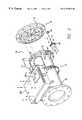
- FIG. 2is a partially exploded pictorial view of an exhaust valve system constructed in accordance with a preferred embodiment of the invention
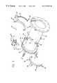
- FIG. 3is a partially exploded pictorial view of another embodiment of the exhaust valve system
- FIG. 4is an enlarged exploded view of rotating plate structure in the valve that enables the adjustable control of airflow through the valve;
- FIG. 5is a partially exploded view showing the gear drive and magnet connection
- FIG. 6is a view of a duct plate
- FIG. 7is an exploded view of an interior magnet assembly.
- FIG. 1schematically illustrates a typical minienvironment system.
- Supply airis delivered into the minienvironment via a fan-filter unit or module 1 .
- the supply airpasses through the process tool area and is exhausted through a vent or ductwork, as shown at 3 .
- a damper 5is used to control the volumetric flow of the exhaust.
- This type of minienvironment systemis familiar to those who are knowledgeable about silicon wafer manufacturing operations.
- FIG. 2illustrates an improved exhaust valve system 10 that is designed to replace the damper 5 shown in FIG. 1 .
- the valve system 10is designed for installation as a modular unit that can be installed in the exhaust ductwork of existing minienvironments without significant structural modifications.
- the valve system 10has a tubular section or tube 12 that carries a volumetric flow sensing system 13 (described in greater detail below) and includes a mechanical arrangement of rotating plates (indicated generally at 14 ) that enable precise adjustment of airflow through the valve system.
- a circular flange 16is connected to one end of the tube 12 to allow attachment of the rotating plate assembly 14 .
- the rotating plate assembly 14has a circular flange 15 , which is connected to the circular flange 16 of the tube 12 , to form a seal. If necessary for a particular application, the seal could be made airtight to prevent the escape of harmful vapors or chemicals.
- the flanges 15 and 16may be bolted or otherwise securely fastened together.
- FIG. 4The various parts of the plate assembly 14 are shown in FIG. 4 . Although in FIG. 3 and FIG. 4, a rotating plate assembly having three plates is shown, it will be apparent to one of ordinary skill in the art that two or any larger number of plates may be used.
- the rotating plate assembly 14has a first plate that is fixed in place. To the fixed plate 100 is rotably connected additional plates.
- FIG. 4shows a second plate 110 and a third plate 120 .
- the three platesmay be connected using a fastener 130 passing through a corresponding opening in the center of each of the three plates and mating with a fastener 132 . There may also be inserted between the plates washers 134 to aid in the attachment of the plates and relative rotation of the plates.
- the fixed plate 100has at least one opening 102 through which air can pass.
- the additional plates 110 and 120have openings 112 and 122 identical in placement and size to those of the fixed plate 100 . Although it is generally preferable to have matched openings, in some applications the openings would not be identical in placement or size.
- plates 100 , 110 , and 120are shown with four openings shaped generally as wedges. The use of wedged-shaped openings has been found to provide good airflow characteristics through the openings. Generally openings with good airflow characteristics are those that provide as little turbulence as possible through a given size opening. Furthermore, for an assembly having three plates as is shown in FIG. 4, the sum of the area of the openings should be approximately two-thirds of the total area of a plate.
- the sum of the area of the openingsshould be approximately three-fourths of the total area of a plate. As will be explained in more detail below, such sizings of the openings will allow the plates to cooperatively interact with each other to completely close the duct.
- the second plate 110has at least one are-shaped slot 114 that is concentric with the plate and has a length equal to approximately one-half the length of the widest part of the opening 112 .
- the third plate 120has a protrusion 124 facing the second plate located such that when the third plate is installed next to the second plate, the protrusion 124 extends into the slot 114 on the second plate 110 .
- the plate assemblyWhen the three plates and associated hardware are assembled to form a rotating plate assembly 14 , the plate assembly operates as follows. When the plates are in a first position such that the openings 102 , 112 , and 122 are all aligned with each other, the open area of the duct is approximately two-thirds the area of a plate. In this position, the protrusion 124 on the third plate is located at a first end of the slot 114 on the second plate. An external force is then applied to the third plate, causing it to rotate relative to the second plate, with the protrusion 124 on the third plate sliding along the slot 114 on the second plate. As the third plate is rotated, the solid portion of the third plate begins to overlap and block the open area of the first and second plates, thereby reducing the amount of open area in the duct.
- the third platemay be rotated relative to the second plate in this manner without causing any rotation of the second plate until the protrusion 124 aligns with a second end of the slot 114 . At this second position, any further rotation of the third plate would necessarily cause a corresponding rotation of the second plate. At this second position, half of the opening in the second plate is covered with the solid portion of the third plate, thereby causing the open area of the duct to be approximately one-third of the area of a plate.
- the second and third plates 110 , 120together function somewhat like a shutter valve in the way they overlap and in the way the rotary actuation of one plate drives the other plate.
- the third plate 120can be moved only within a certain angular range.
- the valve 10is fully open at one end of the range and fully closed at the other.
- other mechanical meanscan be substituted for the protrusions 124 and slots 114 , such as, for example, a ridge or other feature on a first plate that interferes with a ridge or other feature on a second plate. Such other features are found on shutter valves.
- the amount of open area through the rotating plate assemblycan vary infinitely from two-thirds open to completely blocked.
- FIG. 4shows wedge-shaped openings, other shapes such as a perforation pattern, slots, or other opening configurations that allow for sequential overlapping of open areas with solid portions can be used.
- the front side of the plate 120has a forwardly protruding flange 126 along one side of at least one wedge-shaped opening 122 .
- Each flange 126fits within the wedge-shaped opening of the second plate 110 .
- the flange 126presses against one side 116 of the wedge-shaped opening in the second plate 110 .
- the openings in both plates 112 , 122eventually become congruent. In this way, the third plate 120 successively drives the second plate 110 to open the valve.
- the protruding flangeeventually becomes congruent with the opposite side of the opening, causing the second plate to be rotated, thereby closing the valve. Furthermore, the flange operates to improve the seal when the valve is in the closed position.
- one method of applying force to the third plate 120 to cause its rotation within the ductis through use of at least two magnets.
- the third plate 120has at least one interior magnet assembly 128 affixed to a surface that faces away from plates 100 and 110 .
- each magnet 205is installed between a block 207 and a back plane 209 , such that its axis of polarity is radially oriented relative to the rotating axis of the plate.
- the interior magnet assemblies 128may be affixed to the third plate using clamps, screws 212 or other secure fasteners.
- the rotating plate assemblyis attached to the main tube 12 using fasteners to achieve an air-tight seal between the rotating plate assembly and the main assembly.
- the interior magnet assemblies 128 of the rotating plate assemblyare located within the tube aligned with a magnet ring 40 .
- the magnet ringis rotatably engaged with the exterior of the tube in which the interior magnet assemblies 128 are located. As shown in FIG. 5, the magnet ring 40 may be separated into two pieces to aid in assembly.
- the magnet ring 40is designed to receive at least one exterior magnet 42 , corresponding to the number and location of interior magnet assemblies 128 .
- Exterior magnets 42are oriented such that their axis of polarity is in a radial direction relative to the axis of the duct, such that each pair of exterior magnets 42 and interior magnet assemblies 128 may magnetically interact. For example, if the interior magnet assemblies 128 are oriented such that the north polarity faces radially outward from the duct, the exterior magnets 42 will be oriented so that the south polarity faces radially inward toward the duct.
- the amount of interaction between a pair of magnetsis measured in terms of shear force required to break the interaction. It is important that the breakaway force be sufficient to allow a mechanical force to be applied to the magnet ring and the exterior magnets, causing a rotation of the magnet ring to transmit a corresponding force to the interior magnets, causing rotation of the plates. If the breakaway force is not sufficient, the pair or pairs of magnets will break away, and fail to cause rotation of the interior magnet assemblies. Experimentation has shown that the total breakaway force should be at least 20 pounds to ensure that the magnetic coupling will overcome any friction present in the rotating plate assembly. In what is believed to be the best mode, four magnets are used that provide a total breakaway force of 32 pounds.
- mechanical forceis applied to the magnet ring 40 through a rack gear 50 attached to the outer surface of the magnet ring.
- the rack gearmay be attached to the magnet ring by use of fasteners, such as screws 52 .
- the pitch and dimensions of the teeth on the rack gearare sized to receive and interface with the teeth of a pinion spur gear 54 (see FIG. 2) attached to the axle of a stepper motor 56 , which is attached to the tube 12 .
- Stepper motors and the type of gear arrangement just describedare well known.
- the valve system 10is actuated when the stepper motor 56 drives the pinion spur gear 54 in a first rotational direction that, in turn, drives the rack gear, magnet ring, and third plate 120 in the opposite direction as the spur gear.
- the third plate 120initially rotates relative to the second plate 110 (plate 110 remains in the same position because the forward protruding flange 126 next to each wedge-shaped opening pulls away from surface 116 on the second plate 110 ).
- the valveis actuated into either an open or a closed position. Rotation of the stepper motor in the opposite direction actuates the valve in the opposite manner.
- valve system 10is controlled by monitoring the volumetric airflow within the tube 12 . It is difficult, however, to directly measure volumetric airflow. Instead, it is easier to measure the pressure drop across an obstruction, then calculate the corresponding volumetric airflow knowing the relationship between volumetric airflow and pressure for a given diameter tube.
- a series of four pressure sensor unitsare arranged substantially 90 degrees apart around the circumference of the duct.
- Each sensor unitconsists of two taps facing radially into the tube (see FIG. 3) on either side of an obstruction (not shown).
- All upstream pressure ports, relative to the obstructionare connected by a common tube which is then connected to the high side of the differential pressure transducer 17 .
- the common air path in the tubeaverages the pressure from the four ports. This averaging acts to create a more accurate signal and lessens the effects of not having fully developed pipe flow.
- All downstream ports, relative to the obstructionare similarly connected by a common tube which is then connected to the low side of the differential pressure transducer 17 .
- the pressure transducer 17determines the differential pressure and sends a corresponding signal to the programmable logic controller.
- the determination of the pressure dropenables the calculation of the volumetric airflow rate through the tube 12 according to Bernoulli's Obstruction theory, using the equation:
- a dedicated signal processorcan be utilized that monitors changes in the pressure difference on a continuous basis and makes responsive adjustments to the airflow rate through the valve system. It has been discovered that there is a closely linear relationship between the percentage of open area through the rotating plate assembly and the volumetric airflow through the valve. Consequently, the valve system provides precise control in the exhaust section of a clean room duct and the ability to adapt and adjust quickly to flow variations that result from changing conditions inside the minienvironment. In this way, the valve system can be used to maintain the “balance” of the minienvironment as described above.
- a programmable logic controller(“PLC”) (not shown) is used.
- PLCprogrammable logic controller
- the PLC and related circuitryis housed inside control unit 200 .
- control unit 200One of ordinary skill in the art will be able to design the circuitry to calculate the airflow rate given the pressure differential.
- the systemprovides the ability to remotely monitor and control the airflow through the valve.
- the inputs needed to control the systemare a voltage, possibly 24 volts, a signal to toggle between two preprogrammed set points, a signal line to make the valve fully open, and a signal to make the valve fully close.
- the circuitrywill send a signal to drive the stepper motor to open or close the valve as needed to reach the desired flow rate.
- These signalscan be sent through a user terminal 202 on the valve system 10 .
- the valvecan also be controlled and monitored using serial communications.
- the signalscan be in any standard communication protocol format, such as ASCII, PROFIBUS, BACNET, or DEVICENET.
Landscapes
- Engineering & Computer Science (AREA)
- General Engineering & Computer Science (AREA)
- Mechanical Engineering (AREA)
- Chemical & Material Sciences (AREA)
- Combustion & Propulsion (AREA)
- Physics & Mathematics (AREA)
- General Physics & Mathematics (AREA)
- Automation & Control Theory (AREA)
- Air-Flow Control Members (AREA)
Abstract
Description
Claims (7)
Priority Applications (1)
| Application Number | Priority Date | Filing Date | Title |
|---|---|---|---|
| US09/323,591US6192922B1 (en) | 1999-06-01 | 1999-06-01 | Airflow control valve for a clean room |
Applications Claiming Priority (1)
| Application Number | Priority Date | Filing Date | Title |
|---|---|---|---|
| US09/323,591US6192922B1 (en) | 1999-06-01 | 1999-06-01 | Airflow control valve for a clean room |
Publications (1)
| Publication Number | Publication Date |
|---|---|
| US6192922B1true US6192922B1 (en) | 2001-02-27 |
Family
ID=23259863
Family Applications (1)
| Application Number | Title | Priority Date | Filing Date |
|---|---|---|---|
| US09/323,591Expired - Fee RelatedUS6192922B1 (en) | 1999-06-01 | 1999-06-01 | Airflow control valve for a clean room |
Country Status (1)
| Country | Link |
|---|---|
| US (1) | US6192922B1 (en) |
Cited By (53)
| Publication number | Priority date | Publication date | Assignee | Title |
|---|---|---|---|---|
| US20030221709A1 (en)* | 2002-06-04 | 2003-12-04 | Samsung Electronics., Ltd | Dishwasher and method of controlling the same |
| US6676508B1 (en)* | 2003-04-22 | 2004-01-13 | Gerald Graham | Magnetically controlled flow system |
| US6945264B1 (en) | 2004-07-09 | 2005-09-20 | Zurn Industries, Inc. | Flow control valve and method for using the same |
| WO2006046796A1 (en)* | 2004-10-29 | 2006-05-04 | Nano Coatech Co., Ltd. | Valve of gas exhaust system |
| US20070087681A1 (en)* | 2005-09-13 | 2007-04-19 | Cook Matthew D | Method to sense airflow by measuring torque on the damper shaft |
| US20070145158A1 (en)* | 2005-12-27 | 2007-06-28 | American Aldes Ventilation Corporation | Method and apparatus for passively controlling airflow |
| US20070207724A1 (en)* | 2006-03-02 | 2007-09-06 | Coogan James J | Air pressure control system and method |
| KR100764133B1 (en) | 2007-07-31 | 2007-10-08 | 주식회사 삼진정밀 | Porous Variable Orifice Valve |
| US20070246678A1 (en)* | 2006-03-09 | 2007-10-25 | Michaels Gregory A | Rotary valve assembly |
| US20080058966A1 (en)* | 2006-09-05 | 2008-03-06 | Honeywell International Inc. | Single line control for hvac actuator |
| US20080156010A1 (en)* | 2007-01-02 | 2008-07-03 | Lg Electronics Inc. | Refrigerator |
| US20090104051A1 (en)* | 2007-10-17 | 2009-04-23 | Hua-Chiang Wang | Guide device for blowers |
| US20090140183A1 (en)* | 2007-12-03 | 2009-06-04 | Michael Baeuerle | Magnetic transmission |
| US20110260087A1 (en)* | 2010-04-21 | 2011-10-27 | Perr J Victor | Multi-rotor flow control valve |
| BE1018969A5 (en)* | 2009-10-21 | 2011-12-06 | Renson Ventilation Nv | CENTRAL VENTILATION SYSTEM. |
| US20120295530A1 (en)* | 2011-05-18 | 2012-11-22 | Ikeno Naoya | Backflow prevention apparatus of clean room |
| US20130140475A1 (en)* | 2011-12-03 | 2013-06-06 | Big Horn Valve, Inc. | Rotary valve adapter assembly with planetary gear system |
| WO2013119430A1 (en)* | 2012-02-07 | 2013-08-15 | Lam Research Corporation | Pressure control valve assembly of plasma processing chamber and rapid alternating process |
| US20130220424A1 (en)* | 2012-02-23 | 2013-08-29 | Cameron International Corporation | Rotating compressor valve |
| US20130306746A1 (en)* | 2012-05-15 | 2013-11-21 | Daniel Plew, SR. | Retrofit Flap Damper Assembly System for Cone Type Damper Variable Air Volume Boxes |
| KR101343487B1 (en) | 2012-03-20 | 2013-12-19 | 희성소재 (주) | apparatus for sublimation refinement and method of using the same |
| US20130337737A1 (en)* | 2012-06-14 | 2013-12-19 | International Business Machines Corporation | Compressed gas cylinder cabinet with regulated exhaust control |
| KR101356606B1 (en)* | 2012-07-24 | 2014-02-03 | 김경중 | Throttle valve |
| US20150099456A1 (en)* | 2013-10-08 | 2015-04-09 | Airfixture Llc | Air diffuser with manual and motorized plates |
| US20150140922A1 (en)* | 2013-11-21 | 2015-05-21 | Nejat Babur | Constant Total Orifice Area Damper |
| WO2015105603A1 (en)* | 2014-01-09 | 2015-07-16 | Dresser-Rand Company | Grid valve apparatus |
| US20150234391A1 (en)* | 2014-02-20 | 2015-08-20 | Paul Francis Sabadin | Submerged rotor flow control valve |
| US20150253781A1 (en)* | 2014-03-04 | 2015-09-10 | Automatic Airflow Balancing Llc | Airflow balancing valve for hvac systems |
| US20150314152A1 (en)* | 2014-05-05 | 2015-11-05 | Dresser Wayne Ab | Purge and Pressurization System with Feedback Control |
| US20160061797A1 (en)* | 2014-08-28 | 2016-03-03 | Veltek Associates, Inc. | Programmable logic controller-based system and user interface for air sampling in controlled environments |
| CN105626883A (en)* | 2016-02-06 | 2016-06-01 | 江苏信息职业技术学院 | Totally closed cavity non-contact flow control system |
| US9759442B2 (en) | 2005-12-27 | 2017-09-12 | American Aldes Ventilation Corporation | Method and apparatus for passively controlling airflow |
| US9777866B2 (en)* | 2016-02-15 | 2017-10-03 | Jiangsu Vocational College Of Information Technology | Non-contact flow control system having a totally sealed cavity |
| US20180143653A1 (en)* | 2015-05-19 | 2018-05-24 | Exel Industries | Flow control device and mixing system comprising such a device |
| US20180289174A1 (en)* | 2017-04-10 | 2018-10-11 | Hill-Rom Services, Inc. | Mattress overlay for p&v, turn assist and mcm |
| WO2018227438A1 (en)* | 2017-06-14 | 2018-12-20 | 江苏信息职业技术学院 | Non-contact flow rate control system having fully-enclosed cavity |
| CN109899896A (en)* | 2019-02-22 | 2019-06-18 | 德业日本株式会社 | New healthy air clarifier |
| US20190264824A1 (en)* | 2018-02-27 | 2019-08-29 | Honeywell International Inc. | Rotary plate valve systems |
| CN110307070A (en)* | 2019-06-27 | 2019-10-08 | 三一重型装备有限公司 | Gas reversing arrangement and internal combustion engine |
| US10683860B2 (en)* | 2017-03-27 | 2020-06-16 | Burckhardt Compression Ag | Piston compressor valve and method for operating a piston compressor valve |
| US10697445B2 (en)* | 2017-03-27 | 2020-06-30 | Burckhardt Compression Ag | Valve closure for a piston compressor valve and method for operating the valve closure |
| CN112136008A (en)* | 2018-01-17 | 2020-12-25 | 江森自控股份有限公司 | Air brake |
| JP2021504658A (en)* | 2017-11-27 | 2021-02-15 | エーエスエム アイピー ホールディング ビー.ブイ. | Equipment with clean mini-environment |
| CN113550454A (en)* | 2021-08-20 | 2021-10-26 | 湖北中森华泰建筑工程有限公司 | Heat preservation steel structure workshop |
| US11236831B2 (en)* | 2019-02-08 | 2022-02-01 | Liebherr-Aerospace Toulouse Sas | Fluid flow control valve equipped with a conical flap and system comprising such valve |
| US11448420B2 (en)* | 2018-01-17 | 2022-09-20 | Johnson Controls, Inc. | Air duct damper |
| WO2023280567A1 (en)* | 2021-07-09 | 2023-01-12 | Viega Technology Gmbh & Co. Kg | Valve for regulating a flow of a medium |
| US11808674B2 (en) | 2008-02-07 | 2023-11-07 | Veltek Associates, Inc. | System and method for air sampling in controlled environments |
| USD1014731S1 (en) | 2019-01-17 | 2024-02-13 | Johnson Controls Tyco IP Holdings LLP | Damper |
| US12000721B2 (en) | 2018-01-17 | 2024-06-04 | Tyco Fire & Security Gmbh | Air duct airflow sensor with internal low-pressure detector |
| US12038185B2 (en) | 2018-01-17 | 2024-07-16 | Tyco Fire & Security Gmbh | Air duct assembly with field accessible ports in communication with a pressure source and pressure sensing ports in communication with a pressure sensor |
| US12372270B2 (en) | 2018-01-17 | 2025-07-29 | Air Distribution Technologies Ip, Llc | Air duct damper and installation components |
| US12385768B2 (en) | 2022-08-31 | 2025-08-12 | Tyco Fire & Security Gmbh | Air duct airflow sensor |
Citations (19)
| Publication number | Priority date | Publication date | Assignee | Title |
|---|---|---|---|---|
| US1806530A (en)* | 1931-05-19 | Assionob to the pui | ||
| US3347262A (en)* | 1965-09-22 | 1967-10-17 | Mark Associates Inc | Magnet actuated sealed valve |
| US4000754A (en) | 1974-06-11 | 1977-01-04 | Maxton Manufacturing Company | Automatic control valve for a fluid system |
| US4026321A (en) | 1975-12-12 | 1977-05-31 | Kahoe Laboratories, Inc. | Electronic control for constant and variable volume central heating and air-conditioning systems |
| US4277832A (en) | 1979-10-01 | 1981-07-07 | General Electric Company | Fluid flow control system |
| US4554943A (en)* | 1983-12-02 | 1985-11-26 | Fisher Controls International, Inc. | Single disc rotary valve |
| US5107886A (en) | 1991-02-15 | 1992-04-28 | Taylor Julian S | Constant flow orifice valve |
| US5190068A (en) | 1992-07-02 | 1993-03-02 | Brian Philbin | Control apparatus and method for controlling fluid flows and pressures |
| US5218998A (en) | 1992-04-01 | 1993-06-15 | Bakken Gary M | Linearly adjustable |
| US5220940A (en) | 1988-04-07 | 1993-06-22 | David Palmer | Flow control valve with venturi |
| US5251665A (en) | 1992-07-20 | 1993-10-12 | Phoenix Controls Corporation | Mechanism for operating multiple air flow control valves |
| US5304093A (en) | 1992-01-17 | 1994-04-19 | Phoenix Controls Corporation | Method and apparatus for controlling a fluid flow valve |
| US5320124A (en) | 1988-04-07 | 1994-06-14 | Palmer David W | Regulator adaptable for maintaining a constant partial vacuum in a remote region |
| US5456280A (en) | 1988-04-07 | 1995-10-10 | Palmer; David W. | Process-chamber flow control system |
| US5518446A (en)* | 1994-07-28 | 1996-05-21 | Landis & Gyr Powers, Inc. | Fume hood exhaust terminal |
| US5582203A (en) | 1988-04-07 | 1996-12-10 | Palmer; David W. | System for controlling flow through a process region |
| US5597011A (en) | 1988-04-07 | 1997-01-28 | Palmer; David W. | Flow regulator |
| US5634490A (en) | 1988-04-07 | 1997-06-03 | Palmer; David W. | Process-chamber flow control system |
| US5669408A (en) | 1995-06-12 | 1997-09-23 | Fujikin Incorporated | Pressure type flow rate control apparatus |
- 1999
- 1999-06-01USUS09/323,591patent/US6192922B1/ennot_activeExpired - Fee Related
Patent Citations (20)
| Publication number | Priority date | Publication date | Assignee | Title |
|---|---|---|---|---|
| US1806530A (en)* | 1931-05-19 | Assionob to the pui | ||
| US3347262A (en)* | 1965-09-22 | 1967-10-17 | Mark Associates Inc | Magnet actuated sealed valve |
| US4000754A (en) | 1974-06-11 | 1977-01-04 | Maxton Manufacturing Company | Automatic control valve for a fluid system |
| US4026321A (en) | 1975-12-12 | 1977-05-31 | Kahoe Laboratories, Inc. | Electronic control for constant and variable volume central heating and air-conditioning systems |
| US4277832A (en) | 1979-10-01 | 1981-07-07 | General Electric Company | Fluid flow control system |
| US4554943A (en)* | 1983-12-02 | 1985-11-26 | Fisher Controls International, Inc. | Single disc rotary valve |
| US5582203A (en) | 1988-04-07 | 1996-12-10 | Palmer; David W. | System for controlling flow through a process region |
| US5597011A (en) | 1988-04-07 | 1997-01-28 | Palmer; David W. | Flow regulator |
| US5664600A (en) | 1988-04-07 | 1997-09-09 | Palmer; David W. | Process-chamber flow control system |
| US5220940A (en) | 1988-04-07 | 1993-06-22 | David Palmer | Flow control valve with venturi |
| US5634490A (en) | 1988-04-07 | 1997-06-03 | Palmer; David W. | Process-chamber flow control system |
| US5456280A (en) | 1988-04-07 | 1995-10-10 | Palmer; David W. | Process-chamber flow control system |
| US5320124A (en) | 1988-04-07 | 1994-06-14 | Palmer David W | Regulator adaptable for maintaining a constant partial vacuum in a remote region |
| US5107886A (en) | 1991-02-15 | 1992-04-28 | Taylor Julian S | Constant flow orifice valve |
| US5304093A (en) | 1992-01-17 | 1994-04-19 | Phoenix Controls Corporation | Method and apparatus for controlling a fluid flow valve |
| US5218998A (en) | 1992-04-01 | 1993-06-15 | Bakken Gary M | Linearly adjustable |
| US5190068A (en) | 1992-07-02 | 1993-03-02 | Brian Philbin | Control apparatus and method for controlling fluid flows and pressures |
| US5251665A (en) | 1992-07-20 | 1993-10-12 | Phoenix Controls Corporation | Mechanism for operating multiple air flow control valves |
| US5518446A (en)* | 1994-07-28 | 1996-05-21 | Landis & Gyr Powers, Inc. | Fume hood exhaust terminal |
| US5669408A (en) | 1995-06-12 | 1997-09-23 | Fujikin Incorporated | Pressure type flow rate control apparatus |
Cited By (91)
| Publication number | Priority date | Publication date | Assignee | Title |
|---|---|---|---|---|
| US7389782B2 (en)* | 2002-06-04 | 2008-06-24 | Samsung Electronics Co., Ltd. | Dishwasher and method of controlling the same |
| US20030221709A1 (en)* | 2002-06-04 | 2003-12-04 | Samsung Electronics., Ltd | Dishwasher and method of controlling the same |
| US6676508B1 (en)* | 2003-04-22 | 2004-01-13 | Gerald Graham | Magnetically controlled flow system |
| US6945264B1 (en) | 2004-07-09 | 2005-09-20 | Zurn Industries, Inc. | Flow control valve and method for using the same |
| WO2006046796A1 (en)* | 2004-10-29 | 2006-05-04 | Nano Coatech Co., Ltd. | Valve of gas exhaust system |
| US20070087681A1 (en)* | 2005-09-13 | 2007-04-19 | Cook Matthew D | Method to sense airflow by measuring torque on the damper shaft |
| US20070145158A1 (en)* | 2005-12-27 | 2007-06-28 | American Aldes Ventilation Corporation | Method and apparatus for passively controlling airflow |
| US20100227541A1 (en)* | 2005-12-27 | 2010-09-09 | American Aldes Ventilation Corporation | Method and apparatus for passively controlling airflow |
| US10571140B2 (en) | 2005-12-27 | 2020-02-25 | American Aldes Ventilation Corporation | Method and apparatus for passively controlling airflow |
| US7766734B2 (en) | 2005-12-27 | 2010-08-03 | American Aldes Ventilation Corporation | Method and apparatus for passively controlling airflow |
| US9759442B2 (en) | 2005-12-27 | 2017-09-12 | American Aldes Ventilation Corporation | Method and apparatus for passively controlling airflow |
| US9201428B2 (en) | 2005-12-27 | 2015-12-01 | American Aldes Ventilation Corporation | Method and apparatus for passively controlling airflow |
| US20070207724A1 (en)* | 2006-03-02 | 2007-09-06 | Coogan James J | Air pressure control system and method |
| US9605856B2 (en)* | 2006-03-02 | 2017-03-28 | Siemens Industry, Inc. | Air pressure control system and method |
| US20070246678A1 (en)* | 2006-03-09 | 2007-10-25 | Michaels Gregory A | Rotary valve assembly |
| US20120285543A1 (en)* | 2006-03-09 | 2012-11-15 | Michaels Gregory A | Rotary Valve Assembly |
| US8210205B2 (en)* | 2006-03-09 | 2012-07-03 | Michaels Gregory A | Rotary valve assembly |
| US20080058966A1 (en)* | 2006-09-05 | 2008-03-06 | Honeywell International Inc. | Single line control for hvac actuator |
| US7787994B2 (en) | 2006-09-05 | 2010-08-31 | Honeywell International Inc. | Single line control for HVAC actuator |
| US20080156010A1 (en)* | 2007-01-02 | 2008-07-03 | Lg Electronics Inc. | Refrigerator |
| KR100764133B1 (en) | 2007-07-31 | 2007-10-08 | 주식회사 삼진정밀 | Porous Variable Orifice Valve |
| US20090104051A1 (en)* | 2007-10-17 | 2009-04-23 | Hua-Chiang Wang | Guide device for blowers |
| US20090140183A1 (en)* | 2007-12-03 | 2009-06-04 | Michael Baeuerle | Magnetic transmission |
| US8534320B2 (en)* | 2007-12-03 | 2013-09-17 | Robert Bosch Gmbh | Magnetic transmission |
| US12306080B2 (en) | 2008-02-07 | 2025-05-20 | Veltek Associates, Inc. | Flow control modules that transmit desired flow rate |
| US11808674B2 (en) | 2008-02-07 | 2023-11-07 | Veltek Associates, Inc. | System and method for air sampling in controlled environments |
| BE1018969A5 (en)* | 2009-10-21 | 2011-12-06 | Renson Ventilation Nv | CENTRAL VENTILATION SYSTEM. |
| US20110260087A1 (en)* | 2010-04-21 | 2011-10-27 | Perr J Victor | Multi-rotor flow control valve |
| US8720423B2 (en)* | 2010-04-21 | 2014-05-13 | Cummins Inc. | Multi-rotor flow control valve |
| US20120295530A1 (en)* | 2011-05-18 | 2012-11-22 | Ikeno Naoya | Backflow prevention apparatus of clean room |
| US9217576B2 (en)* | 2011-05-18 | 2015-12-22 | Panasonic Intellectual Property Management Co., Ltd. | Backflow prevention apparatus of clean room |
| US20130140475A1 (en)* | 2011-12-03 | 2013-06-06 | Big Horn Valve, Inc. | Rotary valve adapter assembly with planetary gear system |
| WO2013119430A1 (en)* | 2012-02-07 | 2013-08-15 | Lam Research Corporation | Pressure control valve assembly of plasma processing chamber and rapid alternating process |
| CN104105816A (en)* | 2012-02-07 | 2014-10-15 | 朗姆研究公司 | Pressure control valve assembly of plasma processing chamber and rapid alternating process |
| US20130220424A1 (en)* | 2012-02-23 | 2013-08-29 | Cameron International Corporation | Rotating compressor valve |
| US8974201B2 (en)* | 2012-02-23 | 2015-03-10 | Ge Oil & Gas Compression Systems, Llc | Rotating compressor valve |
| KR101343487B1 (en) | 2012-03-20 | 2013-12-19 | 희성소재 (주) | apparatus for sublimation refinement and method of using the same |
| US20130306746A1 (en)* | 2012-05-15 | 2013-11-21 | Daniel Plew, SR. | Retrofit Flap Damper Assembly System for Cone Type Damper Variable Air Volume Boxes |
| US20130337737A1 (en)* | 2012-06-14 | 2013-12-19 | International Business Machines Corporation | Compressed gas cylinder cabinet with regulated exhaust control |
| KR101356606B1 (en)* | 2012-07-24 | 2014-02-03 | 김경중 | Throttle valve |
| US10365006B2 (en)* | 2013-10-08 | 2019-07-30 | Airfixture, Llc | Air diffuser with manual and motorized plates |
| US11578890B2 (en)* | 2013-10-08 | 2023-02-14 | Airfixture, Llc | Air diffuser with manual and motorized plates |
| US20150099456A1 (en)* | 2013-10-08 | 2015-04-09 | Airfixture Llc | Air diffuser with manual and motorized plates |
| US9874369B2 (en)* | 2013-11-21 | 2018-01-23 | Nejat Babur | Constant total orifice area damper |
| US20150140922A1 (en)* | 2013-11-21 | 2015-05-21 | Nejat Babur | Constant Total Orifice Area Damper |
| US9739395B2 (en)* | 2014-01-09 | 2017-08-22 | Dresser-Rand Company | Grid valve apparatus |
| WO2015105603A1 (en)* | 2014-01-09 | 2015-07-16 | Dresser-Rand Company | Grid valve apparatus |
| US20150204455A1 (en)* | 2014-01-09 | 2015-07-23 | Dresser-Rand Company | Grid valve apparatus |
| US20150234391A1 (en)* | 2014-02-20 | 2015-08-20 | Paul Francis Sabadin | Submerged rotor flow control valve |
| US10203703B2 (en)* | 2014-03-04 | 2019-02-12 | Mi Valve, Llc | Airflow balancing valve for HVAC systems |
| US12085299B2 (en) | 2014-03-04 | 2024-09-10 | Greenheck Fan Corporation | Airflow balancing valve for HVAC systems |
| US11281239B2 (en)* | 2014-03-04 | 2022-03-22 | Metal Industries, Llc | Airflow balancing valve for HVAC systems |
| US11054846B2 (en)* | 2014-03-04 | 2021-07-06 | Mi Valve, Llc | Airflow balancing valve for HVAC systems |
| US20150253781A1 (en)* | 2014-03-04 | 2015-09-10 | Automatic Airflow Balancing Llc | Airflow balancing valve for hvac systems |
| US20150314152A1 (en)* | 2014-05-05 | 2015-11-05 | Dresser Wayne Ab | Purge and Pressurization System with Feedback Control |
| US10646734B2 (en)* | 2014-05-05 | 2020-05-12 | Wayne Fueling Systems Sweden Ab | Purge and pressurization system with feedback control |
| US20180224413A1 (en)* | 2014-08-28 | 2018-08-09 | Veltek Associates, Inc. | Programmable logic controller-based system and user interface for air |
| US12422420B2 (en) | 2014-08-28 | 2025-09-23 | Veltek Associates, Inc. | Programmable logic controller-based system and user interface for air sampling in controlled environments |
| US20160061797A1 (en)* | 2014-08-28 | 2016-03-03 | Veltek Associates, Inc. | Programmable logic controller-based system and user interface for air sampling in controlled environments |
| US11971396B2 (en) | 2014-08-28 | 2024-04-30 | Veltek Associates, Inc. | Programmable logic controller-based system and user interface for air sampling controlled environments |
| US9939416B2 (en)* | 2014-08-28 | 2018-04-10 | Veltek Assoicates, Inc. | Programmable logic controller-based system and user interface for air sampling in controlled environments |
| US20180143653A1 (en)* | 2015-05-19 | 2018-05-24 | Exel Industries | Flow control device and mixing system comprising such a device |
| CN105626883A (en)* | 2016-02-06 | 2016-06-01 | 江苏信息职业技术学院 | Totally closed cavity non-contact flow control system |
| CN105626883B (en)* | 2016-02-06 | 2018-04-24 | 江苏信息职业技术学院 | The totally-enclosed contactless flow control system of cavity |
| US9777866B2 (en)* | 2016-02-15 | 2017-10-03 | Jiangsu Vocational College Of Information Technology | Non-contact flow control system having a totally sealed cavity |
| US10683860B2 (en)* | 2017-03-27 | 2020-06-16 | Burckhardt Compression Ag | Piston compressor valve and method for operating a piston compressor valve |
| US10697445B2 (en)* | 2017-03-27 | 2020-06-30 | Burckhardt Compression Ag | Valve closure for a piston compressor valve and method for operating the valve closure |
| US10856668B2 (en)* | 2017-04-10 | 2020-12-08 | Hill-Rom Services, Inc. | Mattress overlay control system with rotary valves and graphical user interface for percussion and vibration, turn assist and microclimate management |
| US11684169B2 (en) | 2017-04-10 | 2023-06-27 | Hill-Rom Services, Inc. | Rotary plate valve having seal anti-herniation structure |
| US20180289174A1 (en)* | 2017-04-10 | 2018-10-11 | Hill-Rom Services, Inc. | Mattress overlay for p&v, turn assist and mcm |
| WO2018227438A1 (en)* | 2017-06-14 | 2018-12-20 | 江苏信息职业技术学院 | Non-contact flow rate control system having fully-enclosed cavity |
| JP2021504658A (en)* | 2017-11-27 | 2021-02-15 | エーエスエム アイピー ホールディング ビー.ブイ. | Equipment with clean mini-environment |
| CN112136008A (en)* | 2018-01-17 | 2020-12-25 | 江森自控股份有限公司 | Air brake |
| US11448420B2 (en)* | 2018-01-17 | 2022-09-20 | Johnson Controls, Inc. | Air duct damper |
| US12372270B2 (en) | 2018-01-17 | 2025-07-29 | Air Distribution Technologies Ip, Llc | Air duct damper and installation components |
| US12000721B2 (en) | 2018-01-17 | 2024-06-04 | Tyco Fire & Security Gmbh | Air duct airflow sensor with internal low-pressure detector |
| US12025335B2 (en) | 2018-01-17 | 2024-07-02 | Johnson Controls, Inc. | Air duct damper |
| US12038185B2 (en) | 2018-01-17 | 2024-07-16 | Tyco Fire & Security Gmbh | Air duct assembly with field accessible ports in communication with a pressure source and pressure sensing ports in communication with a pressure sensor |
| US11333259B2 (en) | 2018-02-27 | 2022-05-17 | Honeywell International Inc. | Rotary plate valve systems |
| US10865896B2 (en)* | 2018-02-27 | 2020-12-15 | Honeywell International Inc. | Rotary plate valve systems |
| US20190264824A1 (en)* | 2018-02-27 | 2019-08-29 | Honeywell International Inc. | Rotary plate valve systems |
| USD1014731S1 (en) | 2019-01-17 | 2024-02-13 | Johnson Controls Tyco IP Holdings LLP | Damper |
| US11236831B2 (en)* | 2019-02-08 | 2022-02-01 | Liebherr-Aerospace Toulouse Sas | Fluid flow control valve equipped with a conical flap and system comprising such valve |
| CN109899896B (en)* | 2019-02-22 | 2021-04-20 | 宁波德业日用电器科技有限公司 | Novel healthy air purifier |
| CN109899896A (en)* | 2019-02-22 | 2019-06-18 | 德业日本株式会社 | New healthy air clarifier |
| CN110307070A (en)* | 2019-06-27 | 2019-10-08 | 三一重型装备有限公司 | Gas reversing arrangement and internal combustion engine |
| CN110307070B (en)* | 2019-06-27 | 2021-11-16 | 三一重型装备有限公司 | Gas reversing device and internal combustion engine |
| US12404937B2 (en) | 2021-07-09 | 2025-09-02 | Viega Technology Gmbh & Co. Kg | Valve for regulating the flow of a medium |
| WO2023280567A1 (en)* | 2021-07-09 | 2023-01-12 | Viega Technology Gmbh & Co. Kg | Valve for regulating a flow of a medium |
| CN113550454A (en)* | 2021-08-20 | 2021-10-26 | 湖北中森华泰建筑工程有限公司 | Heat preservation steel structure workshop |
| US12385768B2 (en) | 2022-08-31 | 2025-08-12 | Tyco Fire & Security Gmbh | Air duct airflow sensor |
Similar Documents
| Publication | Publication Date | Title |
|---|---|---|
| US6192922B1 (en) | Airflow control valve for a clean room | |
| US12085299B2 (en) | Airflow balancing valve for HVAC systems | |
| EP2081663B1 (en) | Building, ventilation system, and recovery device control | |
| US7255012B2 (en) | Process fluid flow device with variable orifice | |
| CN100523666C (en) | Zone damper fault detection in an HVAC system | |
| US5764579A (en) | System for controlling laboratories with fume hoods | |
| US20130068313A1 (en) | Electronic Pressure Independent Controller For Fluid Flow Control Valve | |
| US5518446A (en) | Fume hood exhaust terminal | |
| KR980010210A (en) | Automated Branch Flow Control in Heating Ventilation Air Conditioning (HVAC) Systems | |
| EP2932164B1 (en) | Fast attachment open end direct mount damper and valve actuator | |
| CN109764175A (en) | A kind of control system and method for flow feedback type variable air rate butterfly valve | |
| CN217951255U (en) | Air valve with Venturi detection device and air volume adjusting system | |
| CN217951256U (en) | Air valve with pore plate detection device and air volume adjusting system | |
| JPH085115A (en) | Ventilation method of building | |
| JPH0220903B2 (en) | ||
| US20040038642A1 (en) | Gas flow control systems | |
| CN112136008B (en) | air brake | |
| Devices | 2.25 CONTROL INSTRUMENTATION | |
| US20250109878A1 (en) | Adaptive flow controller for use with a flow control system and method | |
| AU635695B1 (en) | Laboratory fume hood control apparatus having improved safety considerations | |
| JPS62131132A (en) | Outside air intake control device | |
| JP2000028193A (en) | Control system of motor damper, and control board used for it, and motor damper | |
| CN115264716A (en) | Ventilation system and biosafety laboratory | |
| KR20030004941A (en) | A throttle valve for a semiconductor device fabrication installation | |
| JPS59231347A (en) | Air conditioning facility controlling minor differential pressure inside room |
Legal Events
| Date | Code | Title | Description |
|---|---|---|---|
| AS | Assignment | Owner name:HUNTAIR INC., OREGON Free format text:ASSIGNMENT OF ASSIGNORS INTEREST;ASSIGNORS:MACGIBBON, BRUCE S.;WOLOCHUK, MARK C.;WOLOCHUK, LEE I.;AND OTHERS;REEL/FRAME:010198/0861;SIGNING DATES FROM 19990728 TO 19990823 | |
| AS | Assignment | Owner name:SYNETICS SOLUTIONS INC., OREGON Free format text:ASSIGNMENT OF ASSIGNORS INTEREST;ASSIGNOR:HUNTAIR INC.;REEL/FRAME:010881/0889 Effective date:20000612 Owner name:HUNTAIR INC., OREGON Free format text:ASSIGNMENT OF ASSIGNORS INTEREST;ASSIGNORS:MACGIBBON, BRUCE S.;WOLOCHUK, MARK C.;WOLOCHUK, LEE I.;AND OTHERS;REEL/FRAME:010889/0927 Effective date:19990728 | |
| FPAY | Fee payment | Year of fee payment:4 | |
| REMI | Maintenance fee reminder mailed | ||
| LAPS | Lapse for failure to pay maintenance fees | ||
| STCH | Information on status: patent discontinuation | Free format text:PATENT EXPIRED DUE TO NONPAYMENT OF MAINTENANCE FEES UNDER 37 CFR 1.362 | |
| FP | Lapsed due to failure to pay maintenance fee | Effective date:20090227 | |
| AS | Assignment | Owner name:BROOKS AUTOMATION US, LLC, MASSACHUSETTS Free format text:ASSIGNMENT OF ASSIGNORS INTEREST;ASSIGNOR:BROOKS AUTOMATION HOLDING, LLC;REEL/FRAME:058482/0001 Effective date:20211001 Owner name:BROOKS AUTOMATION HOLDING, LLC, MASSACHUSETTS Free format text:ASSIGNMENT OF ASSIGNORS INTEREST;ASSIGNOR:BROOKS AUTOMATION,INC;REEL/FRAME:058481/0740 Effective date:20211001 |