US6192118B1 - Computer telephone system and method having a graphical user interface - Google Patents
Computer telephone system and method having a graphical user interfaceDownload PDFInfo
- Publication number
- US6192118B1 US6192118B1US09/056,597US5659798AUS6192118B1US 6192118 B1US6192118 B1US 6192118B1US 5659798 AUS5659798 AUS 5659798AUS 6192118 B1US6192118 B1US 6192118B1
- Authority
- US
- United States
- Prior art keywords
- call
- user
- window
- displayed
- directory
- Prior art date
- Legal status (The legal status is an assumption and is not a legal conclusion. Google has not performed a legal analysis and makes no representation as to the accuracy of the status listed.)
- Expired - Lifetime
Links
- 238000000034methodMethods0.000titleclaimsdescription237
- 230000006870functionEffects0.000abstractdescription36
- 230000008569processEffects0.000description72
- 230000009471actionEffects0.000description55
- 230000008859changeEffects0.000description25
- 230000008676importEffects0.000description22
- 230000008901benefitEffects0.000description13
- 238000013461designMethods0.000description11
- 230000036316preloadEffects0.000description11
- 238000012546transferMethods0.000description11
- 238000004891communicationMethods0.000description8
- 238000013475authorizationMethods0.000description6
- 230000007246mechanismEffects0.000description5
- 238000012790confirmationMethods0.000description4
- 238000010586diagramMethods0.000description4
- 230000004044responseEffects0.000description4
- 230000007704transitionEffects0.000description4
- 230000001186cumulative effectEffects0.000description3
- 238000013507mappingMethods0.000description3
- 238000012545processingMethods0.000description3
- 230000000007visual effectEffects0.000description3
- 230000006399behaviorEffects0.000description2
- 230000001419dependent effectEffects0.000description2
- 230000000994depressogenic effectEffects0.000description2
- 238000012544monitoring processMethods0.000description2
- 101100060181Mus musculus Clock geneProteins0.000description1
- 230000004075alterationEffects0.000description1
- 230000005540biological transmissionEffects0.000description1
- 238000006243chemical reactionMethods0.000description1
- 238000010276constructionMethods0.000description1
- 230000003247decreasing effectEffects0.000description1
- 238000005516engineering processMethods0.000description1
- 230000000977initiatory effectEffects0.000description1
- 230000002452interceptive effectEffects0.000description1
- 208000003580polydactylyDiseases0.000description1
- 238000012163sequencing techniqueMethods0.000description1
- 230000011664signalingEffects0.000description1
- 230000003068static effectEffects0.000description1
- 238000006467substitution reactionMethods0.000description1
- 230000001960triggered effectEffects0.000description1
Images


Classifications
- H—ELECTRICITY
- H04—ELECTRIC COMMUNICATION TECHNIQUE
- H04M—TELEPHONIC COMMUNICATION
- H04M1/00—Substation equipment, e.g. for use by subscribers
- H04M1/247—Telephone sets including user guidance or feature selection means facilitating their use
- H04M1/2473—Telephone terminals interfacing a personal computer, e.g. using an API (Application Programming Interface)
- H—ELECTRICITY
- H04—ELECTRIC COMMUNICATION TECHNIQUE
- H04M—TELEPHONIC COMMUNICATION
- H04M1/00—Substation equipment, e.g. for use by subscribers
- H04M1/26—Devices for calling a subscriber
- H04M1/27—Devices whereby a plurality of signals may be stored simultaneously
- H04M1/274—Devices whereby a plurality of signals may be stored simultaneously with provision for storing more than one subscriber number at a time, e.g. using toothed disc
- H04M1/2745—Devices whereby a plurality of signals may be stored simultaneously with provision for storing more than one subscriber number at a time, e.g. using toothed disc using static electronic memories, e.g. chips
- H04M1/27467—Methods of retrieving data
- H04M1/27475—Methods of retrieving data using interactive graphical means or pictorial representations
- H—ELECTRICITY
- H04—ELECTRIC COMMUNICATION TECHNIQUE
- H04M—TELEPHONIC COMMUNICATION
- H04M1/00—Substation equipment, e.g. for use by subscribers
- H04M1/56—Arrangements for indicating or recording the called number at the calling subscriber's set
- H—ELECTRICITY
- H04—ELECTRIC COMMUNICATION TECHNIQUE
- H04M—TELEPHONIC COMMUNICATION
- H04M1/00—Substation equipment, e.g. for use by subscribers
- H04M1/57—Arrangements for indicating or recording the number of the calling subscriber at the called subscriber's set
- H04M1/575—Means for retrieving and displaying personal data about calling party
- H—ELECTRICITY
- H04—ELECTRIC COMMUNICATION TECHNIQUE
- H04M—TELEPHONIC COMMUNICATION
- H04M2250/00—Details of telephonic subscriber devices
- H04M2250/60—Details of telephonic subscriber devices logging of communication history, e.g. outgoing or incoming calls, missed calls, messages or URLs
Definitions
- This inventionrelates generally to telecommunications systems, and more particularly to software and telephone systems that may be used to allow for telephone operations to be performed using personal computers.
- Telephone systemshave been previously developed for use with personal computers. Existing systems, however, are often difficult to use and contain only a limited number of features that users may desire. Such systems do not normally provide robust interfaces to other communications devices such as systems for electronic mail, voice mail, video, facsimile, etc. Many existing systems also are designed for a particular type of computer and may not be easily converted for use on different types of computers. Similarly, the software for many existing systems is difficult to modify to add additional features.
- prior systemshave not fully capitalized on the ability to identify incoming calls and the ability to build and use a database of information about called and calling parties. While prior art systems have provided some automated directory services, they have not provided the full range of database processing with the flexibility of a graphical user interface.
- a telecommunications systemis provided that is constructed using a client server architecture.
- Client processesreside on personal computers available to each user of the system. These personal computers are connected to one another and to a server computer through a local area network.
- the server computeris connected to a private branch exchange (PBX) which is, in turn, connected to desktop telephone units available to each user.
- PBXprivate branch exchange
- An application program compatible with a typical windowed environmentruns on each personal computer to provide each user with a graphical user interface through which each user may receive and place calls and use other telephone functions.
- each client computermay access the server computer, as necessary, to access the PBX or to access database information stored in or managed by the server computer.
- the server computeritself may comprise another personal computer or a larger computer actually storing the information or the server may act as a gateway to information stored on other platforms.
- the local time and location of a calling party of a telephone callis displayed for the benefit of a user of the system.
- the systemcaptures automatic number identification (ANI) or Caller ID or DNIS information data for the telephone call.
- the systemmay capture information input by the calling party. This information might be input by the calling party in response to an Interactive Voice Response system. At least a portion of the ANI or Caller ID data may then be used to access database information to determine the place of origin and the local time of the calling party. The local time and place may then be displayed to the user of the system.
- ANIautomatic number identification
- Caller ID or DNIS information datafor the telephone call.
- the systemmay capture information input by the calling party. This information might be input by the calling party in response to an Interactive Voice Response system. At least a portion of the ANI or Caller ID data may then be used to access database information to determine the place of origin and the local time of the calling party. The local time and place may then be displayed to the user of the system.
- the present inventionmay also allow the city and state from which a caller is calling to be displayed to a user of the system. This again allows for more efficient communication between the parties.
- the amount of time a call has been on holdmay also be displayed for each telephone call currently in progress with a particular user. Because the hold time may be displayed for each call separately, the user may readily determine how long each party has been on hold and may, for example, handle calls in order from the longest to the shortest time on hold. Because a hold timer is maintained for each call to a user, an employer of the user may log hold timer data for use in monitoring the employee's performance in answering and processing calls in an expeditious manner.
- the telephone systemallows a user to simultaneously view all calls currently in progress with that user.
- the userneed not remember which call was on which line because information about the call appears in a call information/control object.
- the useralso can easily determine how long a call has proceeded or how long a person has been on hold by looking at a call status object.
- the usercan further perform telephone functions on a call by selecting telephone function buttons within the call information/control object.
- An important advantage of the telephone function buttonsis that they present options to a user that are dynamic depending on the state of a call. Accordingly, the telephone function buttons presented to a user represent only valid functions that may be performed on a call in a particular state.
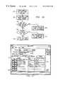
- FIG. 1illustrates a computer telephone system constructed in accordance with the teachings of the present invention
- FIG. 2illustrates a computer system that may be used in the computer telephone system illustrated in FIG. 1;
- FIG. 3illustrates a second embodiment of a computer telephone system constructed in accordance with the teaching of the present invention
- FIG. 4illustrates an embodiment of a server that may be used in the computer telephone system of FIG. 1;
- FIG. 5illustrates a window that may be used with a GUI object builder of the present invention
- FIG. 6illustrates a screen which may appear while using the GUI object builder
- FIG. 7illustrates objects that may be created by the user of the GUI object builder
- FIG. 8illustrates an architecture for a GUI object builder
- FIG. 9illustrates two views of the tool bar for the GUI object builder, one in design mode and one in run time mode
- FIG. 10illustrates an embodiment of the architecture that may be used to allow multi-user access to a single user database
- FIG. 11illustrates an example of a database control process that may be used to provide multi-user access to a single user database
- FIG. 12illustrates an embodiment of an in-memory database constructed in accordance with the teachings of the present invention
- FIG. 13illustrates an embodiment of a method to achieve automatic updates of shared records in the computer telephone system of FIG. 1;
- FIG. 14illustrates a directories window that may be used with the present invention
- FIG. 15illustrates the directory window of FIG. 14 with multiple directories opened simultaneously
- FIG. 16illustrates an add directory window that may be used to add additional directories to the computer telephone system illustrated in FIG. 1;
- FIG. 17illustrates a directory properties window that may be used to customize the properties of directories used in computer telephone system 10 ;
- FIG. 18illustrates the directory customization window that may be used to further customize phone directories used in computer telephone system 10 ;
- FIG. 19illustrates an embodiment of a process that may be used to add and customize directories for computer telephone system 10 ;
- FIG. 20illustrates a custom dial plan window that may be used to create custom dial plans for use with computer telephone system 10 ;
- FIG. 21illustrates a custom dial plan associated with an exemplary telephone number
- FIG. 22illustrates an extended phone number information window that may be used to associate a dial plan with a telephone number in the computer telephone system of FIG. 1;
- FIG. 23illustrates a make and answer calls preferences window that may be used to set the dial plan override feature in the computer telephone system of FIG. 1;
- FIG. 24illustrates an example procedure that may be used to add or update a custom dial plan in the computer telephone system of FIG. 1;
- FIG. 25illustrates an example of a process that may be used to add or update a phone number in a directory using the computer telephone system of FIG. 1;
- FIG. 26illustrates a procedure that may be used to implement a dial plan override feature in the computer telephone system of FIG. 1;
- FIG. 27illustrates a color coded folder that may be associated with a directory entry used in the computer telephone system of FIG. 1;
- FIG. 28illustrates a color coded folder that may be associated with a directory entry used in the computer telephone system of FIG. 1;
- FIG. 29illustrates a color coded folder that may be associated with a directory entry used in the computer telephone system of FIG. 1;
- FIG. 30illustrates a color coded folder that may be associated with a directory entry used in the computer telephone system of FIG. 1;
- FIG. 31illustrates an import window that may be used to import directory information from other applications for use with the computer telephone system of FIG. 1;
- FIG. 32illustrates a network directory services import window that may be used to import information using Novell's Netware Directory Service (NWDS) in the computer telephone system of FIG. 1;
- NWDSNovell's Netware Directory Service
- FIG. 33illustrates an example of a procedure that may be used to implement the Netware/network directory services import feature for use with the computer telephone system of FIG. 1;
- FIG. 34illustrates a make and answer calls window that may be used with the computer telephone system of FIG. 1;
- FIG. 35illustrates an example of a process that may be used to display all active calls in a call window in the computer telephone system of FIG. 1;
- FIG. 36illustrates a call window for a user with no calls in progress for the computer telephone system of FIG. 1;
- FIG. 37illustrates a call window for a user with a single call in progress in the computer telephone system in FIG. 1;
- FIG. 38illustrates a call window for a user with a conference call and another call and a non-conferenced call in progress using the computer telephone system of FIG. 1;
- FIG. 39illustrates a block diagram of the system used to arrange a call window for the computer telephone system of FIG. 1;
- FIG. 40illustrates a flow chart of a procedure used to update the call window of FIG. 39 in accordance with telephony events received by the computer telephone system of FIG. 1;
- FIG. 41illustrates how call information may be displayed in expanded or compressed form in the call window that may be used with the computer telephone system of FIG. 1;
- FIG. 42illustrates a make and answer calls preferences window that may be used to set user preferences in the computer telephone system of FIG. 1;
- FIG. 43illustrates an example of a procedure that may be used to change the size of a call object based upon a size preference setting set in the window of FIG. 42;
- FIG. 44illustrates call information that may appear in a call window used with the computer telephone system of FIG. 1;
- FIG. 45illustrates an example of a process used to display call information in a hierarchical fashion in the call window illustrated in FIG. 44;
- FIG. 46illustrates a hold timer displayed for a call received by a user of the computer telephone system of FIG. 1;
- FIG. 47illustrates a procedure used to maintain a hold timer for each call received or placed by a user of computer telephone system 10 ;
- FIG. 48illustrates an example of a procedure used to display the city and state and local time of a caller participating in a call with a user of a computer telephone system construction according to the teachings of the present invention
- FIG. 49illustrates how a user of computer telephone system 10 may only be presented with valid telephone functions depending upon the various states of a telephone call
- FIG. 50illustrates a state table used by computer telephone system 10 to maintain the proper display illustrated in FIG. 49;
- FIG. 51illustrates an example of a procedure used to display only valid telephone function options to a user of the computer telephone system of FIG. 15;
- FIG. 52illustrates a window that shows how a user may create a teleconference in a single step for the computer telephone system of FIG. 1;
- FIG. 53illustrates the result of creation of a teleconference using the window of FIG. 52;
- FIG. 54illustrates an example of a procedure used to implement the single step conferencing feature illustrated in FIGS. 52 and 53;
- FIG. 55illustrates the availability of a conference all control button used with the computer telephone system of FIG. 1;
- FIG. 56illustrates the result of pressing the conference all button of FIG. 55
- FIG. 57illustrates a procedure used to implement the conference all feature illustrated in FIGS. 55 and 56;
- FIG. 58illustrates the ability of a user of the computer telephone system of FIG. 1 to conduct selective conferencing
- FIG. 59illustrates the result of a user creating a selective conference using the window illustrated in FIG. 58;
- FIG. 60illustrates a procedure used by the computer telephone system illustrated in FIG. 1 to implement the selective conferencing feature
- FIG. 61illustrates a procedure used by the computer telephone system illustrated in FIG. 1 to implement the selective conferencing feature
- FIG. 62illustrates how a call may be added to an existing teleconference in a single step using the computer telephone system of FIG. 1;
- FIG. 63illustrates the results of adding a telephone call to an existing teleconference using the window illustrated in FIG. 62;
- FIG. 64illustrates an example of a procedure used to add a new call to an existing teleconference as illustrated in FIGS. 62 and 63;
- FIG. 65illustrates a merged call option feature used with the computer telephone system illustrated in FIG. 1;
- FIG. 66illustrates a window that results from pressing the merge call control button illustrated in FIG. 65;
- FIG. 67illustrates the availability of a merge call control option when more than two calls are displayed in a call window in a computer telephone system of FIG. 1;
- FIG. 68illustrates the result of pressing the merge call button for the window illustrated in FIG. 67;
- FIG. 69illustrates the call window after two calls have been merged using the window illustrated in FIG. 68;
- FIG. 70illustrates procedures used to implement the merge call feature for the computer telephone system of FIG. 1;
- FIG. 71illustrates procedures used to implement the merge call feature for the computer telephone system of FIG. 1;
- FIG. 72illustrates how some or all calls in a teleconference may be controlled by call control buttons for a conference controller used with the computer telephone system of FIG. 1;
- FIG. 73illustrates the result of controlling all calls in a conference using the window of FIG. 72;
- FIG. 74illustrates the display of valid phone features in the computer telephone system of FIG. 1;
- FIG. 75illustrates speed dial icons used with the computer telephone system of FIG. 1;
- FIG. 76illustrates a speed dial set-up window used with the computer telephone system of FIG. 1;
- FIG. 77illustrates a window used to search for a name in a directory with the computer telephone system of FIG. 1;
- FIG. 78illustrates a window used to search for a name in a directory with the computer telephone system of FIG. 1;
- FIG. 79illustrates the results of searching for a name using the search defined in the windows illustrated in FIGS. 77 or 78 ;
- FIG. 80illustrates how searching for a name may be done using a partial string of the name in the computer telephone system of FIG. 1;
- FIG. 81illustrates the results of searching using the partial string illustrated in FIG. 80;
- FIG. 82illustrates the search of a name in a directory entry in the computer telephone system of FIG. 1;
- FIG. 83illustrates the result of the search of FIG. 82 when only one name was found in the directory for the search string
- FIG. 84illustrates extended phone number information that allows a user to establish a primary number in the computer telephone system of FIG. 1;
- FIG. 85illustrates how a primary number is dialed as a result of a search for the name of the party found during the search using computer telephone system of FIG. 1;
- FIG. 86illustrates a procedure used to search for directory entries in the computer telephone system of FIG. 1;
- FIG. 87illustrates a global search window used to conduct a global search of the directories of the computer telephone system illustrated in FIG. 1;
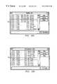
- FIG. 88illustrates a redial list generated by the computer telephone system of FIG. 1;
- FIG. 89illustrates an unanswered calls list generated by the computer telephone system of FIG. 1;
- FIG. 90illustrates an example of a procedure to generate the redial list of FIG. 88
- FIG. 91illustrates a procedure used to generate the unanswered calls list of FIG. 89
- FIG. 92illustrates a more digits feature used with the computer telephone system of FIG. 1;
- FIG. 93illustrates the operation of the dial more digits feature used with the computer telephone system of FIG. 1;
- FIG. 94illustrates the operation of the dial more digits feature used with the computer telephone system of FIG. 1;
- FIG. 95illustrates the operation of the dial more digits feature used with the computer telephone system of FIG. 1;
- FIG. 96illustrates an example of a procedure to implement the dial more digits feature for use with the computer telephone system illustrated in FIG. 1;
- FIG. 97illustrates an example of a procedure used to implement the dial more digits feature for use with the computer telephone system illustrated in FIG. 1;
- FIG. 98illustrates a procedure used to transfer call information with a call in the computer telephone system of FIG. 1;
- FIG. 99illustrates a window used with a voice mail tool provided as part of the computer telephone system of FIG. 1;
- FIG. 100illustrates a window used with a voice mail tool provided as part of the computer telephone system of FIG. 1;
- FIG. 101illustrates a window used with a voice mail tool provided as part of the computer telephone system of FIG. 1;
- FIG. 102illustrates a window used with a voice mail tool provided as part of the computer telephone system of FIG. 1;
- FIG. 103illustrates a window used with a voice mail tool provided as part of the computer telephone system of FIG. 1;
- FIG. 104illustrates a window used with a voice mail tool provided as part of the computer telephone system of FIG. 1;
- FIG. 105illustrates a window used with a voice mail tool provided as part of the computer telephone system of FIG. 1;
- FIG. 106illustrates a window used with a voice mail tool provided as part of the computer telephone system of FIG. 1;
- FIG. 107illustrates a window used with a voice mail tool provided as part of the computer telephone system of FIG. 1;
- FIG. 108illustrates an example of a procedure used to implement a voice mail feature used with the computer telephone system of FIG. 1;
- FIG. 109illustrates an example of a procedure used to implement a voice mail feature used with the computer telephone system of FIG. 1;
- FIG. 110illustrates an example diagram of a voice mail system interfaced using software included with the computer telephone system of FIG. 1;
- FIG. 111illustrates an example of a procedure used to log calls for the computer telephone system of FIG. 1 .
- FIGS. 1 through 111 of the drawingslike numerals being used for like and corresponding parts of the various drawings.
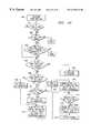
- FIG. 1illustrates an embodiment of a computer telephone system 10 constructed in accordance with the teachings of the present invention.
- Computer telephone system 10comprises a plurality of telephones 12 , a plurality of client computer system 14 a server computer system 16 and a Private Branch Exchange (PBX) 18 .
- Each telephone 12may be connected to PBX 18 .
- Each client computer system 14may be, for example, a general purpose digital computer such as an IBM-compatible personal computer running the Microsoft DOS operating system and the Microsoft Windows operating environment.
- Each client computer system 14may be connected to server computer system 16 using a computer network 17 .
- Computer network 17may comprise an ethernet or token ring local area network or a wide area network.
- Server computer system 16may be a general purpose computer that may also comprise a suitable IBM-compatible personal computer. Server computer system 16 may be connected to PBX 18 . Server computer system 16 and client computer system 14 may also be connected to other systems such as, for example, a voice mail system (not explicitly shown). Server computer system 16 may actually comprise several independent hardware servers, each responsible for providing separate services to the client computer system 14 . In addition, there may be a plurality of each type of service provided to a client. For example, a single client 14 may be serviced by more than one database server, central office telephone line, E-mail system or PBX.
- server computer system 16may act as a gateway to remote systems such as mainframe or other database storage systems connected to server computer system 16 through, for example, a wide area network.
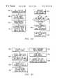
- a client computer system 14may serve as a hardware platform to run, for example, one or more application programs 20 , one or more client service programs 22 through 34 and an operating system 36 .
- Applications 20may provide various services to a user using client service programs 22 through 34 .
- Each of the client service programs 22 through 34may access internal or external hardware and software through operating system 36 to provide services to applications 20 .
- Client service programs 22 through 34may include database client service provider 22 , network client service provider 24 , telephony client service provider 26 , E-Mail client service provider 28 , voice mail client service provider 30 , video client service provider 32 and fax client service provider 34 .
- server computer system 16may comprise operating system 38 and server service providers 40 through 54 .
- Server service providers 40 through 54may interact with client computer system 14 to provide services to client computer system 14 .
- Server service providers 40 through 54may also interact with other internal or external hardware or software such as PBX 18 to aid in providing services to client computer system 14 .
- Server service providers 40 through 54may use operating system 38 to interface with client computer system 14 and PBX 18 .
- server service providers 40 through 54include database server service provider 40 , network server service provider 42 , telephony server service provider 44 , PBX interface server service provider 46 , E-Mail interface server service provider 48 , voice mail interface server service provider 50 , video interface server service provider 52 , and fax interface server service provider 54 .
- FIG. 2illustrates a general purpose computer system 56 that may be used for client computer system 14 and/or server computer system 16 .
- General purpose computer system 56may be adapted to execute any of the well known, MS-DOS, PC-DOS, OS 2 , Unix Motif, MAC-OSTM, X-Windows, WindowsTM Operating Systems or other environments.
- General purpose computer system 56comprises microprocessor 58 , random access memory (RAM) 60 , read-only memory (ROM) 62 , mouse 64 , keyboard 66 , and input/output devices, such as printer 68 , disk drives 70 , and display 72 .
- the present inventionincludes computer software that may be stored in RAM 60 , ROM 62 , or disk drives 70 and is executed by microprocessor 58 .
- disk drives 70may include a variety of types of storage media such as, for example, floppy disk drives, hard disk drives, CD ROM drives, or magnetic tape drives.
- FIG. 3illustrates a second embodiment of computer telephone system 10 constructed in accordance with the teachings of the present invention. Although most aspects of the present invention are described below in the context of a client/server architecture such as that illustrated in FIG. 1, the present invention may also be used with a Centrex system such as that illustrated in FIG. 3 .
- computer telephone system 10comprises general purpose computer 56 , and telephone 12 .
- Computer telephone system 10is connected to central office 80 through Centrex line 76 .
- General purpose computer 56is connected to central office 80 using telephone interface software 78 and Centrex line 76 .
- client software 82 and server software 84are executed on general purpose computer 56 .
- client software 82may interface with server software 84 using various modules contained in client software 82 , server software 84 and operating system 36 .
- Client software 82may include one or more applications 20 , and one or more of the client service programs 22 through 34 described previously.
- Server software 84may include one or more server service providers 40 through 54 described previously.
- E-mail server 48is shown and telephony server 44 is shown coupled to central office 80 in FIG. 3 .
- database server 40is shown.
- Database server 40is shown coupled to a remote database server 41 which may optionally provide additional database services and may be coupled to computer 56 through, for example, a wide area network.
- computer telephone system 10may employ a client/server architecture, the same general purpose computer 56 may serve as the hardware platform for the software systems associated with both client computer system 14 and server computer system 16 described previously.
- the client/server architecturemay allow multiple client computer system 14 to make ‘virtual’ connections to one or more servers 16 such as, for example, a telephony server. Communications between client computer system 14 and server computer system 16 may be performed using a two-way highway of communication. Two-way communication may occur, for example, using two different mechanisms.
- an eventmay cause a message to be generated and sent to the other side of the virtual connection.
- the receiver of the messagewill pick up the message and act upon it.
- no back propagation of success or failurewill normally be generated as it is informational only.
- telephony server service provider 44may send a message to a client computer system 14 to communicate that a telephone call has been received by PBX 18 and is directed at the client computer system 14 .
- Client computer system 14may receive this message and may enable certain user interface options which may represent service requests such as requests for answering the call.
- Server computer system 16may not listen for any success indication as the message is informational only. Server computer system 16 normally will not track the success or failure of the message action.
- Server computer system 16may track whether the message was picked up and, if not, may store information about the call in a call received database for later retrieval by client computer system 14 .
- the concept of server computer system 16 tracking whether events generated by it are picked up by client computer system 14should be considered to be distinct from the concept of whether actions taken by a client computer system 14 due to a message were successful or not.
- a second type of communicationmay include a request for service. Ordinarily, when this type of communication is used, a requester process is blocked from further requests until server computer system 16 completes the servicing of the request. In the case of multiple threading of processes, multiple requests may be made by the requester because the requester may spawn child processes which carry out the action of requesting the service and handling request errors. Child processes may generate new messages to send to the parent upon successful completion such that the parent process may update any user interface tools or data structures.
- a mapping programmay map telephony requests to the formats used by different service application program interfaces (APIs) such as the Telephony Application Program Interface (TAPI) used by Microsoft and Intel and/or the Telephony Services Application Program Interface (TSAPI) used by Novell and AT&T.
- APIsservice application program interfaces
- TAPITelephony Application Program Interface
- TSAPITelephony Services Application Program Interface
- the mapping programmay also bypass the mapping functions and serve as an API for various services.
- Computer system 10may also be used with various PBX systems and/or first party services. The ability of computer telephone system 10 to interface with various service providers allows client applications 20 to target the mapping program without regard for the first or third party API set required to carry out requests.
- Computer telephone system 10may also be used with an automated client reconnect feature.
- server computer system 16may have down time which can present problems for client computer system 14 who have connections that are no longer valid.
- Computer telephone system 10may employ an automatic client reconnect mechanism in which server computer system 16 notifies client computer system 14 when it becomes operational.
- requests from client computer system 14are terminated using network time outs.
- all calls logsare still maintained by server computer system 16 .
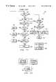
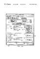
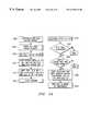
- FIG. 4illustrates an embodiment of server computer system 16 that may be used in computer telephone system 10 .
- Server computer system 16comprises client support service provider 86 , server service providers 40 through 54 , low level service providers 88 through 98 and event processor 104 .
- Client support service provider 86communicates with server service providers 40 through 54 , which in turn communicate with low level service providers 88 through 98 .
- Each server service providermay be associated with a low level service provider such as low level voice mail service provider 88 , low level video service provider 90 , low level database service provider 92 , low level E-mail service provider 94 , low level fax service provider 96 , and low level telephony service provider 98 .
- each other low level service provider 88 through 96may include components similar or identical to low level telephony service provider 98 .
- each other low level service provider 88 through 96may also communicate with event processor 104 in the manner to be described.
- Low level telephony services provider 98comprises request queue 100 , event queue 102 and switch interface server service provider 46 .
- telephony server service provider 44receives telephony service requests from client support service provider 86 .
- Telephony server service provider 44provides these requests to request queue 100 using an API.
- Request queue 100sends these requests to switch interface server service provider 46 .
- Switch interface server service provider 46sends requests to and receives messages from PBX 18 . After receiving a message from PBX 18 , switch interface server service provider 46 sends these messages to event queue 102 using an API.
- Event queue 102may send the messages to event processor 104 that may then send notifications to client; computer system 14 .
- telephony server service provider 44may determine that PBX 18 is not capable of performing a request. In such a case, telephony server service provider 44 may generate a message directly and place it in event queue 102 or send the message directly to event processor 104 although the connection between these blocks is not explicitly shown in FIG. 4 .
- the architecture of computer telephone system 10is designed to be information-independent as the client server architecture is capable of creating a virtual connection between a client and server regardless of the type of information to be communicated. Moreover, the system may be implementation-independent as the architecture employs API's to access implementation-dependent hardware and software. The use of APIs and especially the mapping program of the present invention isolates the various components of the system architecture from the machine dependent variables of systems providing services to those components.
- low level database service provider 92may include the in-memory database system described below, a multi-user database system, or a single user database system with the multi-user virtual interface described below.
- the embodiment illustrated in FIG. 4employs both an in-memory database and a single user database with the multi-user virtual interface described below.
- This embodimentmay use the C-tree database engine available from Faircom or the Btrieve database engine available from Btrieve.
- Other database softwaremay also be used by interfacing appropriate APIs.
- FIG. 5illustrates a window 106 used in the design mode of the GUI object builder.
- Window 106comprises tool bar 108 which contains a plurality of objects 110 .
- each object 110may be represented by an icon.
- the GUI object buildercauses an object of that type to be created.
- Table 1lists the objects 110 associated with each icon illustrated in FIG. 5 according to the icon's position. Other objects could also be used with the GUI object builder.
- FIG. 6illustrates a screen which may appear on display 72 while using the GUI object builder. After the designer clicks on an object 110 using the mouse 64 , that object is dynamically created. Double clicking on an object with the mouse or highlighting an object and pressing the “enter” key causes the object detail window 112 appears on display 72 to allow the designer to define various details about the object.
- a mouse pointer whose position is controlled by mouse 64may appear on display 72 .
- the phrase “click the mouse,” or variants thereof,refers to pressing a button on mouse 64 when the mouse pointer is located on top of a certain object on display 72 .
- the designermay assign various properties to the object as well as define how the object reacts to an event. Specifically, for each event, the designer may specify one or more actions that should be taken in response to an event in a user defined order.
- Eventsmay correspond to systems mentioned above such as the graphical user interface, the telephony system, database system, E-mail system, fax system, video system, and/or voice mail system. Examples of GUI events may include a button being pressed on mouse 64 , the mouse pointer being moved, or an object being disabled.
- Telephony eventsmay include a call being placed on hold, a call arriving, or a call being terminated.
- the output of the GUI object buildermay be external files that contain the layout and behavior of each designer-created object.
- definition filesmay be input directly in the run time mode of the GUI object builder. No compilation is required, although a compiler may be used to create a more compressed image of the information and decrease load time.
- Definition filesare platform independent and may be created by the design tool of the present invention running on any of the supported platforms and used automatically in all supported platforms without any conversion.
- Object definitionsmay be arranged in a hierarchial manner. For example the levels from highest to lowest may be application, window, designer defined objects, and core objects. Examples of core objects may include buttons, labels, text entries, multi-column list boxes and folders. A designer may combine core objects into higher level objects and assign names to them.
- FIG. 7illustrates several higher level objects that have been created by a designer and duplicated in Window 2 as shown. Specifically, FIG. 7 illustrates a number of low level objects such as the numeric labels and buttons. These low level objects have been grouped into a high level object of a window labeled “Window 2 ”.
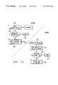
- FIG. 8illustrates the architecture of an embodiment of GUI object builder 114 .
- GUI object builder 114comprises GUI 116 , event action processor 118 , system interfaces 120 through 130 , network interface 132 , start-up control 134 and object definitions storage 136 .
- designer 138creates an application by defining objects that are stored in object definition storage 136 .
- the remaining components of GUI object builder 114are primarily used in run time mode, although the designer 138 may create object definitions 136 using GUI 116 (not explicitly shown).
- GUI object builder 114is driven by event action processor 118 .
- Event action processor 118may be considered to be an application 20 .
- Event action processorreceives messages associated with all events from GUI 116 and each of the interfaces 120 through 130 .
- Event action processor 118interacts with GUI 116 and each of the interfaces 120 through 130 using requests. Each request may be initiated by an event.
- Event action processor 118maintains the state of objects and systems and can be queried at any time. Queried states are returned as messages to objects, which, in turn, initiate requests responsive to the received messages.
- Event action processor 118receives object definitions upon start-up from start-up control 134 .
- Start-up control 134retrieves object definitions from object definition storage 136 .
- Graphical user interface 116may be part of operating system 36 and interfaces with devices such as mouse 64 and display 72 .
- Event action processor 118may be an application 20 .
- Telephony interface 120 , database interface 122 , E-mail interface 124 , voice mail interface 126 , fax interface 128 and video interface 130are each a part of the corresponding client service provider 22 through 34 .
- Network interface 132is controlled by network client service provider 24 .
- GUI object builder 114automatically adjusts to the mode of operation being in design mode or run-time mode.
- FIG. 9illustrates how tool bar 108 may change depending upon the mode of GUI object builder 114 .
- tool bar 108shows low level objects used for design as illustrated in the window labeled OBJDSGN.
- tool bar 108may become a launcher used for launching applications created with GUI object builder 114 .
- the window labeled InTouch 2illustrates tool bar 108 in run time mode.
- Computer telephone system 10may be used with a database system designed to be used only by a single user. Multiple user access to a single user database may be provided using a database control process. In this embodiment, all access requests to the database are sent through the control process. The control process analyzes incoming requests to ensure that a current unit of work is not intermixed with other database requests.
- a unit of workmay be defined as a group of database requests enclosed within a begin request and an end request.
- database accessis limited to only the process executing the unit of work except that Read Only units of work which are not the currently executing unit of work are permitted to execute unless the currently executing unit of work has requested exclusive control of the database. If exclusive control has been requested then read only requests are queued.
- FIG. 10illustrates an example of an architecture for allowing multiple user access to a single user database.
- Each client computer system 14sends database requests through database control process 140 .
- Database control process 140may be, for example, part of the database server service provider 40 .
- Database control process 140controls database transactions with single user database 142 .
- Read queue 144 and update queue 146aid database control process 40 handling request which are not part of the current unit of work and must be deferred until later.
- database control process 140In general, the theory of operation of database control process 140 is to execute requests that are part of the current unit of work and queue those requests that are not part of the current unit of work. Two different queues are maintained by database control process 140 .
- the first queue, read queue 144stores read requests and the second queue, update queue 146 , stores update and add record requests.
- database control process 140executes the END request, signaling the end of the current unit of work, it pulls the next queued request from read queue 144 and begins execution of the new request.
- database control process 140When read queue 144 is emptied, database control process 140 then pulls a request from update queue 146 . This process continues until read queue 144 and update queue 146 have been emptied.
- Read queue 144contains those database requests which do not update the database files.
- Update queue 146may contain those database requests which will alter the database files.
- the above method of operationis designed to send only atomic operations to database 142 .
- database 142operates as if only a single user is accessing the database.
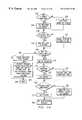
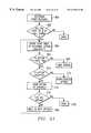
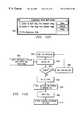
- FIG. 11illustrates a flow chart of one embodiment of database control process 140 .
- a database requestis received by database control process 140 and it is determined whether a unit of work is currently active. As discussed above, a unit of work is active when database control process 140 is processing a database request. In step 148 , therefore, database control process 140 is checking to see whether any database request is currently being processed. If a unit of work is not active, the current request may be executed and execution proceeds to step 150 .
- a time out timeris set in case the stream of database requests from a client computer system 14 is interrupted. Should transmission of a database request from a client computer system 14 be interrupted, the timer that was set in step 150 may cause an interrupt. Interrupts may occur after a predetermined amount of time such as, for example, thirty seconds. When the interrupt occurs, the current unit of work is discarded.
- step 152After each database request is executed in step 152 , execution proceeds to step 154 where it is determined whether the end of a particular unit of work has been received. If not, execution proceeds to step 156 where database control process 140 pauses and waits for the next database request. If, however, the request executed in step 152 was the end of a unit of work, then execution proceeds to step 158 .
- step 158database control process 140 determines whether read queue 144 is empty. If so, flow then proceeds to step 162 where it is determined whether update queue 146 is empty. If read queue 144 is not empty, a request is pulled off of read queue 144 in step 160 , followed by a return to step 148 .
- step 162if it is determined that update queue 146 is empty, then database control process 140 pauses and waits for another database request to be received illustrated in step 166 . If update queue 146 is not empty, execution proceeds to step 164 where a pull request is generated to update queue 146 . The request pulled from update queue 146 is then processed beginning at step 148 .
- step 168database control process 140 determines whether the owner of the currently active unit of work generated the request received in step 148 . If so, then that request is executed in step 152 . If not, then execution proceeds to step 170 .
- step 170it is determined whether the request received at step 148 is a read request. If so, then the request is put on read queue 144 as illustrated in step 174 . Database control process 140 then pauses in step 176 and waits for another database request to arrive. If it is determined in step 170 that a read request was not received, then the request is placed on update queue 146 in step 172 . Then, in step 176 , database control process 140 pauses to wait for another database request.
- the disclosed database control processmakes computer telephone system 10 less expensive because multi-user databases tend to be more expensive than single user database systems. As such, the use of database control process 140 results in a cost savings to users of computer, telephone system 10 .
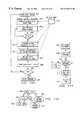
- FIG. 12illustrates an in-memory database 182 .
- In-memory database 182is a part of database server service provider 40 .
- Most database systemsstore data on disk drives 70 . Often, however, it may be desirable to store data for a database in RAM 60 , or in virtual memory.
- the use of in-memory database 182may be most desirable where the data for storage in the database will not be maintained permanently and where an application needs fast access to that data.
- in-memory database 182may receive data record insert/update requests from applications 20 . In-memory database 182 may also receive data record retrieval requests from applications 20 and provide those data records to applications 20 .
- Provisionsmay be made within in-memory database 182 for efficient storage of variable length data items, sequencing of data based upon application defined keys, and rapid retrieval of data items.
- In-memory database 182may employ, for example, an ISAM style database paradigm for storing and accessing data. Records may be stored in any order and one or more indexes may be created to provide an application-determined sequence to the data. In addition, indexes may support the concept of being sparse, meaning that data records must normally meet specific criteria to be included in the index.
- In-memory database 182may be available in two formats, private and shared.
- a private databasemay be available for use by a single process. In this context, all memory allocated by the database is private and may not be accessed by other processes running on the machine.
- Private databasesmay be most efficient in terms of memory management and data access. However, they normally will not serve more than the creating process. Private, memory databases may be created using an API.
- Shared databasesmay be created by a single process and may be available for use by all processes within the system.
- the creating processmay specify, for example, a 128 character name for the database and all processes that provide the correct name may be granted access to the database.
- Memory used in storing this type of databasemay be allocated as shared objects.
- In-memory database codemanages access to the appropriate databases created by new processes.
- the creator of a databasemay also specify that a database is read only.
- the process creating the databasemay be the only process permitted to update the database. All other database users may be restricted to reading the database only.
- Shared in-memory databasesmay be created using an appropriate API and access to an existing shared database may also be obtained using the appropriate API.
- client computer system 14may employ a client/server architecture, multiple client computer systems 14 may be using shared data simultaneously. Because a client computer system 14 may update a shared record at any time, it is desirable to immediately update information being used by client computer system 14 when that information is changed. For example, when multiple client computer systems 14 are using a phone directory and information for that directory is updated, all client computer system 14 may desire to have that change reflected in the information that they are currently viewing.
- FIG. 13illustrates a flow chart of an example process to achieve automatic updates of shared records in computer telephone system 10 .
- a shared database recordhas just been updated and stored in the database as a result of an update request received, for example, from a client computer system 14 .
- a broadcast record typeis a record shared by multiple client computer system 14 where client computer system 14 desire to know when such a record has been changed. If the record is not of this type, then the process is completed in step 190 . If the record is a broadcast record, execution proceeds to step 188 .
- step 188a broadcast synchronization message is sent to all active client computer systems 14 .
- This messageinforms each client that a database record has been updated and also provides each client computer system 14 with the actual data that was updated.
- Broadcast synchronization messagesare received by a client computer system 14 in step 192 .
- the synchronization messageis sent to all active windows as illustrated in step 194 .
- the records sent in step 194are then processed in step 196 to determine whether that data is currently being displayed in an active window. If the data is not being displayed, then it need not be updated and execution terminates at step 198 . If the data is being displayed, the data is updated in all active windows at step 200 .
- each client computer system 14may always display the most current information. A user may avoid using erroneous data that may have been in use by client computer system 14 in the absence of an automatic update.
- Computer Telephone System 10may include a number of telephone directory features. These features may be supported using computer software running on client computer system 14 and server computer system 16 .
- the features described belowmay interface with the user through an application 20 , various client service programs 22 through 34 , operating system software 36 , operating system software 38 and various server service providers 40 through 54 .
- the software in the embodiments described belowreceives input from the user primarily from keyboard 66 and mouse 64 on a client computer system 14 and provides output to the user using display 72 associated with a particular client computer system 14 .
- the embodiments described belowmay also use databases which use database server service provider 40 on server computer system 16 .
- the features described belowmay also interface with PBX 18 using telephony client service provider 26 , operating system 36 , operating system 38 , and telephony server service provider 44 .
- Computer telephone system 10may allow a user to create custom telephone directories. The user may designate whether these directories are to be private or shared. A private directory may be accessed only by the user that created the directory. A shared directory may be accessed by all users of the system. Both private and shared directories may only be updated by the creator of the directory.
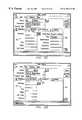
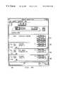
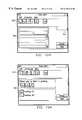
- FIG. 14illustrates a directories window 202 . that may be used with the present invention.
- the window 202allows a user to visually determine whether a telephone directory is private or shared.
- a usermay create any number of directories and have access to a predetermined number of directories at any one time. In the example illustrated in FIG. 14 , the user has access to eight directories. The user may access these directories using directory icons.
- directories window 202 illustrated in FIG. 14the user currently has eight active directories on toolbar 222 .
- Four of these directoriesare personal directories while four of these directories are shared directories.
- Private directoriesmay be represented by private directory icons 208 while shared directories may be represented by shared directory icons 210 .
- a private directory icon 208may be represented by a folder having a single tab while a shared directory icon 210 may be represented by a folder having multiple tabs. In other words, a user may immediately determine whether a directory is private or shared simply by viewing the icon representing that directory.
- iconspresent an efficient method of presenting a user with a large volume of information
- a userwill sometimes forget what directory is represented by a specific directory icon such as icons 208 through 210 .
- the present inventionallows a user to quickly determine the name of a directory without having to perform a number of steps.
- a userwill normally use mouse 64 when performing operations in directories window 202 .
- directories window 202the user may reveal the name of a directory simply by passing the mouse pointer over the surface of a directory icon 208 through 210 .
- the directory namewill then appear in the position of directory name indicator 212 .
- the directory namecould be displayed beginning underneath the corresponding directory icon 208 through 210 .
- directories window 202 illustrated in FIG. 14the user has passed the mouse pointer (not explicitly shown) over the second private directory icon 208 .
- This iconhas a silhouette of a person.
- the present inventionthus allows a user to easily determine the name of a directory represented by an icon without having to perform a series of steps.
- the present inventionallows a user to automatically open one or more directories without having to perform multiple steps or page through a number of menus.
- a directorymay be opened simply by clicking mouse 64 on one of the directory icons 208 through 210 .
- the present inventiongives the user a visual indication of which directories are open and which directories are not open.
- the background of a Directory Icon 208 through 210may be light colored.
- the background of a directory icon 208 through 210may be a shaded color.
- the left-most private directory icon 208has a light-colored background and represents an open directory. All other private directory icons 208 and shared directory icons 210 have shaded backgrounds and represent closed directories. In addition, the shading of the directory icon 208 is changed to appear as a “depressed” button when the directory associated with directory icon 208 is active.
- clicking mouse 64 on one of the directory icons 208 through 210opens that directory or closes the directory based on the current state of the system and the type of mouse clock performed.
- directoriesWhen one or more directories are open, their contents are displayed as directory contents 206 .
- the number of entries in that directorymay be displayed in directories window 202 with the number of records indicator 204 .
- the contents of a directorymay be displayed in expanded or compressed mode. Clicking the mouse 64 on expand/compress icon 214 may toggle the display of the directory contents 206 between expanded and compressed mode.
- directory contents 206may reflect all numbers in the directory for a particular name. For example, if the directory includes a home phone number, fax number, and mobile telephone number, these numbers will all be displayed in expanded mode. In compressed mode, however, only the one number marked by the user as the primary number is displayed for each directory entry.
- the present inventionalso allows for efficient creation of directories and editing of active directories. For example, a new directory may be added by clicking the mouse on add directory entry icon 216 . An entry may be added to an existing directory by clicking mouse 64 on add directory entry icon 218 . A user may edit, or add information to, an existing entry in a directory by clicking on open entry icon 220 .
- Another feature of computer telephone system 10allows a user to open any number of telephone directories at any one time. These directories may be sorted and merged together and displayed to a user as one continuous directory. A user may choose to sort the directories using any field of the directory data.
- FIG. 14illustrates a single open directory.
- FIG. 15illustrates directory window 202 when multiple directories have been opened simultaneously. All four directories illustrated in FIG. 15 are open, as indicated by the light background of private directory icons 208 and the “depressed” shading of the icons.
- the present inventionmay arrange the merged directory listings alphabetically, as illustrated in FIG. 15, but any criteria may be used for sorting the merged directories for display to the user in directory window 202 .
- a usermay simply click on the appropriate icon using mouse 64 while holding down a control key. If a user does not desire to open multiple directories, but simply desires to switch from one directory to another, the present invention avoids the need to close the first directory and then open the second directory. Instead, all open directories are closed automatically when the user clicks on a directory icon 208 through 210 for the directory that the user desires to open.
- Add directory window 224allows a user to designate the name of a directory and whether that directory is a private directory or shared directory. After a new directory has been added, the user may designate that directory as the default directory using directory properties window 226 illustrated in FIG. 17 . Directory Properties Window 226 may appear to the user after a new directory is created using add directory window 224 in FIG. 16 . After the above steps, the user may be given the opportunity to customize the directory.
- FIG. 18illustrates directory customization window 228 .
- the present inventionallows the user to enter a caption to be displayed when the mouse pointer passes over the corresponding directory icon 208 through 210 as described above.
- the usercan also choose a unique icon for each directory.
- Directory customization window 228also allows a user to designate whether or not to preload the directory when directories window 202 is first opened. In other words, a user may desire certain directories to always be opened when the user uses computer telephone system 10 . The user may specify these directories by designating a preload for each such directory in directory customization window 228 .
- a usermay designate preload in the embodiment illustrated in FIG. 18 by causing an X to appear in preload box 230 .
- the usermay cause an X to appear in preload box 230 by clicking mouse 64 on preload box 230 . If user clicks again on preload box 230 , the X will disappear and the directory will not be preloaded when directory window 202 first opens.
- FIG. 19illustrates a flow chart of an example process by which directories may be added and customized.
- Step 232it is determined whether the user wishes to add a directory which is private. If the user wishes to add a private directory, the directory is added as private in step 234 . If the user desires a shared directory, the directory is added as a shared directory in step 236 . Execution from step 234 or step 236 proceeds to step 238 where it is determined whether the user desires to set the new directory as the default directory. If the user does not desire to set the new directory as a default directory, the initial directory becomes the default directory in step 242 . If the user does desire the new directory to be the default directory, the new directory is set as the default directory in step 240 .
- step 244it is determined whether the user desires to add the directory to the directories toolbar 222 . If the user does not desire to add the directory to the directories toolbar 222 , execution proceeds to Step 246 where it is determined whether the user desires to delete a directory from the toolbar 222 . If so, execution proceeds to step 250 where the directory's presence is removed from the toolbar 222 . Note that directories that are removed from the toolbar 222 still exist but are simply not accessible from the phone directory toolbar 222 . After a directory is removed, the procedure terminates in Step 248 .
- step 248If no directory is to be deleted from toolbar 222 , the process terminates in step 248 . If the user did desire to add a directory to the directory toolbar 222 in step 244 , the directory is added to the toolbar 222 in step 245 . After the directory is added, the user has the option of adding a caption to the directory in step 252 . If the user chooses to add a caption, that caption is added in step 253 . If the user does not desire to place a caption on the directory, the caption automatically takes on the directory name in step 254 .
- step 256the user indicates whether he desires to preload phone directories. If the user does not desire to preload phone directories, the directory and its entries are set to be loaded on demand in step 258 . If the user does desire to preload phone directories, the directory is set to be preloaded in step 257 . After executing steps 257 or 258 , the user sets the icon position on toolbar 222 for the new directory in step 260 .
- Computer telephone system 10may also include customized dial plans that may be separate from the phone numbers. Each phone number stored in a directory may be associated with a dial plan. Dial plans may be used to automate the dialing of access codes, PIN numbers, credit card numbers and other numeric dial strings. For example, a user may desire to use one telephone credit card for personal calls and another telephone credit card for business calls. In computer telephone system 10 , a user can establish a dial plan for each credit card and use each dial plan when appropriate. If a user always calls certain numbers for business, the user may designate the appropriate dial plan to be used with those numbers.
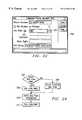
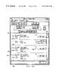
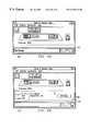
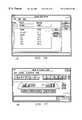
- FIG. 20illustrates custom dial plan window 262 that may be used to create a custom dial plan.
- the usermay give each dial plan a name by entering dial plan name 264 .
- a userwill often need to use a network prefix to obtain an outside line.
- the usermay sometimes have to dial 9 to obtain an outside line.
- 9has been entered as a network prefix. After entering a network prefix, some delay typically occurs before an outside line may be accessed.
- the comma after the 9 in network prefix 266indicates that the system should pause for a predetermined time after the 9 has been entered.
- the usermay also include an access number 268 and authorization code 270 in a custom dial plan. Sometimes, a user needs to dial access number 268 , followed by the phone number that the user is calling, followed by authorization code 270 . Other times, however, the access number 268 and authorization code 270 both must be dialed before dialing the phone number.
- the present inventionallows the user to designate the dial order using dial order selection 276 . In the example illustrated in FIG. 20, the user has selected the order—access number 268 , phone number, authorization code 270 .
- Local call selection 272 and toll call selection 274allow a user to designate whether to send an access number 268 with each local call and/or with each toll call. Local call selection 272 and toll call selection 274 may also allow the user to either send or not send an authorization code 270 with each local call or with each toll call.
- Custom dial plan window 262also can display the dial string 278 that will be dialed when the user makes a call.
- Dial string 278is updated dynamically as data is entered in other fields to give the user a viausl indication of what digits will be dialed.
- the network prefix “ 9 ”will be dialed, followed by the access number “ 567 ,” followed by the phone number to be dialed, followed by the authorization code “ 6578 ”.
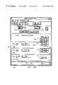
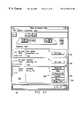
- FIGS. 21 and 22illustrate how a dial plan may be associated with a telephone number.
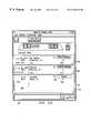
- FIG. 21illustrates directory entry window 280 .
- Directory entry window 280may display a directory entry for one particular person.
- directory window 280illustrates the directory entry for Bob Atkins.
- Each directory entrymay include a phone number folder 282 which lists a plurality of phone numbers associated with that directory entry.
- Bob Atkinshas four phone numbers associated with his directory entry—his office number, fax number, pager number and extension.
- Each numbermay have the same dial plan assigned to it or different dial plans may be associated with each number. If no dial plan is associated with a number, a default dial plan may be used when dialing that number.
- Phone number folder 282may indicate whether a dial plan has been selected for a given number by the presence or absence of a dial plan icon 284 . In this example, dial plan icon 284 appears only after the first phone number for Mr. Atkins. This indicates that a dial plan has been associated with this number, but the other three phone numbers for Mr. Atkins will use a default dial plan.
- a usermay assign or unassign a dial plan to a particular phone number using extended phone number information window 288 .
- the usermay also change the selected dial plan using this window.
- a usermay access extended phone number information window 288 by clicking mouse 64 on extended phone number information icon 286 .
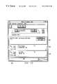
- FIG. 22an example extended phone number information window 288 is illustrated.
- This window 288is for the first phone number in phone number folder 282 illustrated in FIG. 21 .
- the usermay associate or disassociate a dial plan with the number by clicking mouse 64 on dial plan on/off icon 290 .
- the usermay choose which dial plan to associate with the number using dial plan select bar 292 .
- dial plan select bar 292When the user clicks the mouse on dial plan select bar 292 , a list of available dial plans may appear and the user need only scroll down and select the appropriate dial plan.
- An advantage of the present inventionis that a user may easily use computer telephone system 10 on a portable computer while traveling.
- a userneed only design a call plan for the particular location. For example, hotels often have telephone systems where a series of numbers must be dialed to obtain access to an outside line. If a user is in such a hotel, the user may simply create a new dial plan and use computer telephone system 10 with that new dial plan.
- FIG. 23illustrates.make and answer calls preferences window 294 .
- the usermay use dial plan option select 296 to override all dial plans associated with numbers in the directory.
- a usermay turn on the override feature by clicking mouse 64 on override dial plan box 298 . Clicking on override dial plan box 298 a second time may turn the override feature off. In this example, the override dial plan has been selected.
- dial plan select bar 300After the user has chosen to override existing dial plans assigned to specific numbers, the user may indicate which dial plan to use for all calls by using dial plan select bar 300 . This dial plan will then be used for all calls that are made from computer telephone system 10 for that user.
- a usermay also travel on business to a different area code or exchange.
- the usermay indicate to computer telephone system 10 both the area code and exchange where the user will be using computer telephone system 10 .
- Computer telephone system 10may then determine whether any call made by the user is a local call or a toll call using an area code/exchange database.
- area codesIn certain area codes, all exchanges are local calls, while in other area codes, calls between certain exchanges are toll calls. In large cities, like Chicago, a city may have multiple area codes such that calls between two different area codes are still local calls. Accordingly, a database of area codes and exchanges may be used to determine whether a call to a particular area code or exchange is a local call or a toll call. As long as the user indicates the proper area code and exchange from which he is calling, computer telephone system 10 will dial the correct number of digits in accordance with the selected dialing plan.
- FIG. 24illustrates a flow chart of an example procedure for adding or updating a custom dial plan.
- a dial plan namemay be entered by the user. If a dial plan name is not entered, then the user may select an existing dial plan in step 304 . If a user does enter a dial plan name, then that dial plan name is stored at step 306 and will be used for the dial plan. In step 308 , all relevant information for the dial plan may be entered. Then, in to step 310 , the dial plan may be saved in accordance with information added by the user.
- FIG. 25illustrates an example procedure for adding or updating a phone number in a directory.
- the userenters the phone number digits.
- the userthen has the option in step 314 of accepting a default type of number or creating a new type. If the user desires to create his own type, flow proceeds to step 316 where the user may choose a phone number type from the list. If the user desires to use a default type, the default may be assigned in step 318 .
- step 320the user is given the option of accepting the default telephone directory in which the directory entry will be placed. If the user desires to use the default directory, that directory is assigned at step 321 . If the user does not desire to use the default directory, the user is given the option in Step 322 of selecting a private directory. If the user desires to place the entry in a private directory, the user may select the appropriate private directory at step 326 . If the user does not desire to select a private directory, the user may select a shared directory at step 324 .
- step 328the user may choose to assign a custom dial plan to the phone number. If the user does choose to assign a custom dial plan, that dial plan is assigned in step 332 using extended phone number information window 288 as described above. If the user does not desire to assign a custom dial plan to the number, the system default dial plan is assigned to that number in step 330 . From step 330 or 332 execution proceeds to step 334 where the phone number record is added to a database.
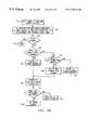
- FIG. 26illustrates an example procedure for the dial plan override feature.
- the userenters a phone number on the make and answer calls window dial pad. All data about the phone number entered may be returned from the database at step 336 .
- the systemdetermines in step 338 whether the make and answer calls dial plan override is turned on. If dial plan override is turned on, then the override dial plan selected in dial plan select bar 300 will be used in step 340 to dial the number. If dial plan override is not on, the system then determines whether the phone number has a custom dial plan assigned to it in step 342 . If a custom dial plan has been assigned, the dial plan that is associated with the number is used to dial that number in step 344 . If no dial plan has been associated with the number, then the default dial plan may be used to dial the number in step 346 .
- FIGS. 27 through 30illustrate folders that may be associated with each directory entry. Again, the directory entry for Bob Atkins has been used as an example.
- FIG. 27illustrates phone number information folder 282 .
- FIG. 28illustrates business information folder 352 .
- FIG. 29illustrates personal information folder 354 .
- FIG. 30illustrates notes folder 356 . These folders illustrate the information that may be stored for each entry in a telephone directory.
- the present inventionemploys several features to make computer telephone system 10 easier to use.
- folders 282 , 352 - 356have both a text entry and an icon on their tabs.
- the foldersmay have color coded borders to indicate which folder is active.
- Each folder 282may also have a color coded folder border 350 .
- phone number folder 282has a blue border (not explicitly shown)
- business information folder 352has a green border (not explicitly shown)
- personal information folder 354has a red border (not explicitly shown)
- notes folder 356has a yellow border (not explicitly shown).
- These bordersmay only be displayed when the particular folder associated with the folder is active. Color coded borders allow a user to immediately recognize which folder is currently active on the screen simply by recognizing the color of folder border 350 .
- Folder icons 348may also be color coded such that folder icons 348 have the same color as folder border 350 when the corresponding folder is currently being displayed. In this way, the user may easily associate the color coded folder border 350 with a particular folder using a similarly colored folder icon 348 .
- the present inventionallows a user to import phone directories created for other applications.
- the usermay import these records using, for example, a text file wherein each line of the text file has a record to be entered and each field in the record is separated by a delimiter which may comprise, for example, a comma.
- the usermay design a map for the import using import map window 358 as illustrated in FIG. 31 .
- Import map window 358comprises database map window 360 , file value window 362 and constant window 364 .
- file value window 362each field in a record from the file to be imported is displayed on a separate line of the window. A position number is assigned to each field in the record. If a field is missing, no entry will appear for that position. For example, in FIG. 31, position number 6 for the record being displayed was empty. The user may scroll through all fields in a record using the scroll bar on the right hand side of file value window 362 .
- the usercan create a map for performing the import using database map window 360 .
- the first column of database map window 360displays the fields available for importation in a directory.
- the usermay scroll through all fields available in a directory using the scroll bar on the right hand side of database map window 360 .
- the useruses drag and drop from the file value window to the database map window.
- position 3 for imported recordsrepresents a name prefix. Accordingly, the user would pick up from position 3 and drop on the name prefix.
- the data associated with the current record from the import file being viewedmay be displayed in column 3 of database map window 360 .
- the userneed not designate the position to be associated with each field using a single record. Instead, the user may view other records using the previous record and next record keys in import window 358 . A user may then determine what type of data should have appeared, for example, at position 6 of an imported record.
- the usermay simply save the map to a file and perform the importation using the saved map.
- Import window 358makes importation easy for a user because the values to be imported are displayed in import window 358 . The user is thus allowed to view the actual data to be imported, allowing easy creation of a mapping in database map window 360 .
- Computer telephone system 10has an additional novel feature. Often, a piece of data may not appear in an import file because the application from which the data is being imported did not support inclusion of that type of data. For example, some systems will not allow a user to specify a company name. If a user knows that the same company name is to be used for all records being imported, the user may specify that company name using constant window 364 . The user may enter the constant to be used in constant window 364 . That constant may then be associated with one of the fields shown in column 1 of database map window 360 . When an importation occurs, the constant from window 364 will be used for that field in all records.
- FIG. 32illustrates Netware import window 366 that may be used to set parameters for a Netware network directory services search.
- Netware import window 366comprises schedule window 368 , phone number format window 370 , and Netware parameter window 372 .
- a usermay set a time to do a Netware directory services import each day.
- phone number format window 370the user may specify whether a full number is to be imported and if not, how many digits are to be imported.
- Netware parameter window 372the user may specify the base object, context, and search filter for the search and also the directory into which the data may be imported.
- FIG. 33illustrates an example Netware directory services search process that may be used in computer telephone system 10 .
- the processbegins at step 374 where it is determined whether it is time to do a Netware directory services import. If not, the process returns to step 374 . If it is time to do a Netware directory services import, execution proceeds to step 376 where a network directory services search is performed using the search criteria previously entered by the user. After the search has been completed, the user's phone book is updated at step 378 for each match found during the search in step 376 . After step 378 , the process may repeat itself by returning to step 374 . Because Netware directory services are commonly used, this aspect of the invention allows a user to use computer telephone system 10 of the present invention with an existing system. Users of computer telephone system 10 may thus have access to changes made in phone numbers by other network users that continue to use Netware network directory services.
- Each user of computer telephone system 10may be provided with a make and answer calls tool for making and answering telephone calls.
- This make and answer calls toolhas many novel features which make a telephone easy to use, more efficient to use, and more powerful.
- the make and answer calls toolruns as one of the application programs 20 described previously.
- FIG. 34illustrates make and answer calls window 380 .
- Make and answer calls window 380may include call window 390 for displaying information about each telephone call in progress.
- a call object 388may be displayed for each call in progress.
- Each call object 388may include a call status object 382 and a call information/control object 384 .
- Scroll bar 386may be used to scroll call window 390 to view all calls displayed in call window 390 .
- Call status object 382may include information about each call. For example, in the embodiment illustrated in FIG. 34, call status object 382 may display information as to whether a call is active, on hold, conferenced, etc. Call status object 382 may also display the corresponding user phone number on which the call was received or placed. For example, in FIG. 34, the call with Mark Stoldt is on extension 5207 and is “on hold”. Call status object 382 may also display information as to how long a call has been in progress and as to how long a caller has been on hold. In the example illustrated in FIG. 34, the call from Larry Mason has been in progress for eight minutes twenty seconds while the call has been on hold for sixteen seconds.
- Call status object 382may also visually indicate whether a call is currently selected or not. When a call is selected, the user may perform various functions on the call. In the example illustrated in FIG. 34, call status object 382 indicates that a call is selected by displaying a light background for call status object 382 . A call which is not selected may have a shaded background for call status object 382 .
- Call information/control object 384displays information about the party to the call with whom the user is speaking.
- call window 390 in FIG. 34is displaying a call from Mark Stoldt of AnswerSoft, a call from extension 5174 in Plano, Tex., and a call from Eric Lambiase of AnswerSoft at extension 5171 in Plano, Tex.
- Call information/control object 384also contains phone function buttons that may be controlled by the user for that particular call.
- the calls that are on hold in FIG. 34display the “Off Hold” option while the active call displays both the “Hang Up” and “Hold” option.
- an important advantage of the present inventionis that the options presented to the user are not static but depend on the state of the call. As such, a call that is already on hold does not have a “Hold” button or, in other words, a user is only presented with meaningful function choices at any state of a call.
- the present inventiontherefore, provides a telephone system 10 that may allow a user to simultaneously view all calls currently in progress with that user.
- the userneed not remember which call was on which line because information about the call appears in call information/control object 384 .
- the useralso can easily determine how long a call has proceeded or how long a person has been on hold by looking at call status object 382 .
- the present inventionthus gives the user immediate visual access to important information about calls in progress.
- FIG. 35illustrates an example of a process that may be used to display all active calls in call window 390 .
- a telephony sessionis established to monitor all calls for a particular device that may be associated with a user. Then, a telephony event is received at step 394 . The process next determines in step 396 whether the event is a new telephone call for the device in question. If a new call for the device has not been received, appropriate call status information associated with the call may be updated in step 398 and the process then may loop back to step 392 . If a new call has been made or received, execution proceeds to step 400 where a new call status object is displayed in call window 390 , along with the appropriate call information. Execution then loops back to step 392 .
- call window 390allows call window 390 to dynamically change in size in accordance with the number of calls in progress.
- Call window 390may also group conference calls together such that they are illustrated separately within call window 390 . This feature of computer telephone system 10 will be described below with reference to FIGS. 36 through 40.
- FIG. 36illustrates call window 390 with no calls in progress. With no calls in progress, call window 390 is small and may not display any information.
- Make and Answer calls window 380still displays the extensions available to that user, a make a call button, redial button, and various other control functions available to the user such as do not disturb, speaker phone and the like.
- FIG. 37illustrates call window 390 with a single call in progress from Eric Lambiase at extension 5171 of AnswerSoft in Plano, Tex.
- Call window 390has expanded to hold call object 388 for the call in progress. Additional active calls may be added at the bottom of call window 390 .
- the single active callmay be hung up, put on hold, conferenced, transferred or parked. As such, buttons for these functions and only these functions are displayed in call object 388 .
- FIG. 38illustrates call window 390 with a conference call in progress and one individual call in progress.
- the conferenceis between the user and two other parties—Larry Mason and Eric Lambiase.
- the individual call in the exampleis with Mark Stoldt.
- the call status objects 382 for the calls participating in the conferenceare grouped together and displayed with conference controller 402 .
- Non-conference callscan be displayed in a group as well.
- the group of non-conference callsconsists of only one call at the bottom of call window 390 .
- a usermay have several conference calls in progress simultaneously. When this occurs, the user may be presented with multiple conference call containers.
- Each conference call containermay contain a conference controller 402 and the call objects 388 for each call participating in that particular conference.
- these conference callsmay be grouped together in discrete units so that the user may keep track of which parties are involved in each conference call and easily move between the conference calls.
- Conference controller 402provides function buttons to allow a user to place all parties to a conference on hold using the hold conference button. A user may also hang up the entire conference by pressing the hang up conference button. The user may release himself from the conference by pressing the drop yourself button. When a party is part of a conference call, that party may be individually dropped or placed on hold using the buttons in call information/control object 384 for that party.
- FIG. 39illustrates how conference containers 404 and a non-conferenced calls container 406 may be arranged in call window 390 .
- a conference container 404is included for each conference call in progress.
- Each conference container 404contains a conference controller 402 and a call object 388 for each party to that particular conference.
- Non-conferenced calls container 406may be placed in call window 390 below the conference containers 404 .
- Non-conference calls container 406may contain a call object 388 for each call in progress that is not part of a conference call.
- a conference container 404may only be visible when a conference is in progress.
- the size of each conference container 404may increase or decrease as call objects 388 are added or removed from a conference container 404 . Calls automatically move from the non-conference calls container 406 to the appropriate conference container 404 when those calls are placed in a conference state. In this embodiment, call objects 388 may always be added at the bottom of a container.
- FIG. 40illustrates an example of a procedure that may be used to update call window 390 in accordance with telephony events that may be received from telephony client service provider 26 and/or telephony server service provide 44 .
- a telephony eventis received.
- call window 390is increased to its maximum height or increased to a height high enough to display the new call object 388 . Execution then proceeds to step 438 to determine whether the call window is at its maximum height with the new call object 388 not visible. If so, then scroll bar 386 is enabled in step 440 . If not, then the procedure is finished.
- step 410if the telephony event was not a new call, then execution proceeds to step 412 to determine whether the telephony event is a new conference. If the event is a new conference, then step 424 is executed to show the associated conference container 404 and conference controller 402 . Execution then proceeds to step 434 to execute the steps described above.
- step 414if the telephony event received was not a new conference, it is then determined in step 414 whether a call is being added to an existing conference. If so, then step 426 is executed and the associated call object 388 is moved from the non-conference calls container 406 to the associated conference container 404 .
- step 416it is determined whether a party to a conference call is being moved to a non-conferenced status. If so, then the call object 388 for the party being removed from the conference is moved from the corresponding conference container 404 to the non-conference calls container 406 at step 428 .
- step 418it is determined in step 418 whether a conference is ending. If a conference is ending, then step 430 is executed where the associated conference container 404 is hidden. Next, the size of call window 390 is decreased to a size large enough to make all call objects 388 visible at step 436 . Execution may then proceed to step 438 .
- step 418if the telephony event received was not the end of a conference, then execution proceeds to step 420 where it is determined whether the event was the end of a call. If not, then the procedure terminates. If so, step 432 is executed where the associated call object 388 is hidden. Execution then continues to step 436 . It should be noted that in each case where the size of call window 390 is adjusted due to a new call, a new conference beginning or a call or conference ending, that the call objects 388 are rearranged in any manner desired. The illustrated embodiment provides one example of how the windows may be rearranged.
- the present inventionallows the user to decide whether they wish to view the call information in call information/control object 384 in an expanded mode or a compressed mode.
- the expanded modea larger number of lines of call status information and a larger number of call control options are visible than in compressed mode.
- up to 8 lines of call status informationmay be displayed in call information/control object 384 and up to 6 call control options may be visible.
- the compressed modefor this embodiment, however, only 2 lines of call status information may be displayed and up to 2 call control buttons may be visible.
- a usermay choose whether to display that call in expanded mode or compressed mode.
- the userhas chosen to display the call from Larry Mason in an expanded mode and the call from Eric Lambiase in a compressed mode.
- the usermay select an expanded or compressed display format for each call object 388 , the user may decide how much information to display for each call according to his needs. This allows the most efficient use of the display area of call window 390 .
- the usermay change from expanded format to compressed format or from compressed format to expanded format using expand/compress icon 442 .
- clicking on expand/compress icon 442 with mouse 64may cause call object 388 to be displayed in compressed form.
- clicking on expand/compress icon 442 with mouse 64may cause call object 388 to be displayed in an expanded mode.
- the present inventionalso allows the user to designate a default display format in which each call object 388 is displayed when it is first placed in call window 390 .
- the usersets these options using call status size option window 444 located in Make and Answer calls preferences window 294 .
- FIG. 42illustrates three options that may be used to specify a default initial size for call object 388 .
- a callmay be always displayed in compressed mode, always displayed in expanded mode or displayed in compressed mode when on hold, etc., and only displayed in expanded mode when the call is active. In the example illustrated in FIG. 42, the user has chosen to always display calls in compressed mode.
- the size of call object 388is determined based upon a size preference setting maintained by the user and/or by a user requested mode for a particular call.
- An example procedure by which computer telephone system 10 determines how to display a particular call object 388is illustrated in FIG. 43 .
- the procedure illustrated in FIG. 43begins at step 446 where a telephony event is received.
- step 448it is determined whether this telephony event is a new call. If the telephony event is not a new call, execution proceeds to step 450 , where it is determined whether the state of a call has changed. If the state of a call has not changed, then the expanded or compressed display format need not cause an adjustment and the procedure terminates.
- a state changeincludes a change in call display formats.
- step 452the system may determine whether a user has previously manually expanded or compressed this call. If so, then the size remains unchanged and the procedure terminates. If not, then execution may proceed to step 454 .
- step 454it may be determined whether a user preference has been set to always display a call in expanded form. If so, then the size, of the call may be set to expanded in step 456 . If not, then execution proceeds to step 458 .
- step 458the system determines whether the user has set a preference to always display calls in a compressed format. If so, then the size of the call is set to be compressed in step 460 . If not, then in step 462 , the system determines whether the current state of the call in question is active. If so, then the size of the call is set to expanded form in step 464 . If not, then the size is set to be compressed form in step 466 . After steps 460 or 466 , execution proceeds to step 470 . After steps 456 or 464 , execution proceeds to step 468 .
- a callis displayed in compressed mode. In this embodiment, up to 2 call control buttons and 2 lines of status information may be displayed while other non-compressed objects are hidden. Execution then proceeds to step 472 .
- a callis displayed in expanded mode. In this embodiment, all available call control buttons and all call status information is displayed. Execution may then proceed to step 472 .
- the new size for display of a callis compared to the current (previous) size. If the sizes are not equal, the call status object is resized to show only visible objects in step 474 .
- call window 390is resized to accommodate the larger or smaller size of the call that has been changed.
- the present inventionemploys a hierarchial display of information about a phone call in call information/control object 384 .
- FIG. 44illustrates the hierarchial display of call information possible with the present invention.
- FIG. 44illustrates 3 calls in call window 390 . The top call is illustrated in expanded mode while the bottom two calls are displayed in compressed mode.
- five linesmay be displayed in call information/control object 384 on five information lines: first information line 478 , second information line 480 , third information line 482 , fourth information line 484 , fifth information line 486 .
- first information line 478 and second information line 480are displayed in call window 390 . More or less lines of information could be displayed in either expanded or compressed mode.
- information about a telephone callis displayed in a hierarchical manner.
- other available informationmay be displayed.
- the two most important pieces of information about a callmay be the name of a caller and the company from which the caller is calling. If these pieces of information are available for a given call, they are displayed in call window 390 in that call's call object 388 . Sometimes, however, this information may not be available. If not, it would be desirable to display other lower priority information that is available. For example, if the name of the caller with which the user is connected is not available, the user may desire for the display to show the phone number from which the caller is calling, or the city and state from which the caller is calling.
- the present inventionallows the highest priority information available about a call to be displayed. Instead of merely displaying empty fields when certain data is unavailable for a call, lower priority data is displayed in place of the missing data.
- first information line 478the name of the party with which the user is speaking, Mark Stoldt
- second information line 480The company, AnswerSoft, Inc., with which Mr. Stoldt is associated
- Third information line 482displays the telephone number to which the user is connected. In other words, third information line 482 displays the number for the telephone from which Mr. Stoldt is calling. In this example, Mr. Stoldt is calling from an extension, 5172 .
- Telephone system 10may obtain the number from which the caller is calling using automatic number identification (ANI) or Caller ID. This information may be provided to an application 20 by telephony client service provider 26 and/or telephony server service provider 44 . After obtaining the telephone number from which the caller is calling, application 20 may determine the caller's name and company name by looking the number up in one of the directories associated with computer telephone system 10 by making a database access request that is then serviced by client database server 22 and server database service 40 .
- ANIautomatic number identification
- Caller IDCaller ID
- This informationmay be provided to an application 20 by telephony client service provider 26 and/or telephony server service provider 44 . After obtaining the telephone number from which the caller is calling, application 20 may determine the caller's name and company name by looking the number up in one of the directories associated with computer telephone system 10 by making a database access request that is then serviced by client database server 22 and server database service 40 .
- Fourth information line 484 in FIG. 44may contain the city and state from which the caller is calling. The manner in which this information may be displayed is discussed below.
- Fifth information line 486may display the local time in the city and state from which the caller is calling. The way that this information is determined is also described below.
- the hierarchy of the informationis caller name, caller company name, caller telephone number, city and state from which caller is calling, and local time in the, city and state from which caller is calling.
- expanded modeall of the available information is displayed in the hierarchial order.
- compressed modea lesser number of information lines 478 through 486 is displayed in call information/control object 384 . As described above, only 2 information lines 478 through 480 are displayed in this example.
- call information/control object 384When a lesser number of information lines are displayed in call information/control object 384 , the highest priority available caller information is displayed.
- the bottom call object 388 in call window 390reflects a call from Eric Lambiase of AnswerSoft, Inc. In this case, the highest priority information, the caller's name and company name were available so that information was displayed.
- the middle call object 388 displayed in call window 390the telephone number of the caller did not appear in a directory so the caller's name and company were not available. In this example, however, the number from which the caller was calling, 5174 , and the city and state from which the caller was calling—Plano, Tex.—were available and were displayed in call information/control object 384 .
- FIG. 45illustrates a flow chart of an example method that may be used to display call information in a hierarchial fashion.
- the procedurebegins with step 488 where information about the call status is retrieved. Execution then proceeds to step 490 where the procedure determines if the caller's name is available in one of the directories. If the name is available, then the caller's name is displayed in step 492 on first information line 478 . If the caller's name was not available, the application 20 determines whether company information for the caller is available at step 496 . If so, then execution proceeds to step 494 where the company information is displayed on first information line 478 .
- the caller's phone number, city and state from which the call originated, and local timewill always be available.
- the procedure illustrated in FIG. 45assumes that this information is available. If the information were not available, the procedure could check to see whether each piece of information was available and display only those items of information available on consecutive information lines 478 through 486 .
- steps 502 , 510 and 518may be executed.
- the phone number of the calleris displayed on second information line 480 .
- the city and stateis displayed on third information line 482 .
- the local time of the calleris displayed on fourth information line 484 .
- step 498it is determined in step 498 if company information is available. If company information is available, steps 500 , 508 , 516 and 524 are executed. In step 500 , company information is displayed on second information line 480 . The caller's phone number is displayed on third information line 482 in step 508 . In step 516 , the city and state from which the caller is calling are displayed on fourth information line 484 . The local time in the city and state from which the caller is calling is displayed on fifth information line 486 in step 524 .
- steps 504 , 512 , and 520are executed.
- the phone number of the calleris displayed on first information line 478 in step 504 .
- step 512the city and state from which the caller is calling is displayed on second information line 480 .
- the local time in the city and state from which the caller is callingis displayed on third information line 482 in step 520 .
- steps 506 , 514 and 522are executed.
- the phone number from which the caller is callingis displayed on second information line 480 .
- the city and state from which the caller is callingis displayed on third information line 482 in step 514 .
- step 522the local time in the city and state from which a caller is calling is displayed on fourth information line 484 .
- the procedure described in FIG. 45provides only one example of how information may be displayed in a hierarchical manner on call object 388 . Other information may be displayed and other hierarchies and/or procedures used without departing from the scope and teachings of the present invention.
- the hierarchical call information display method of the present inventionallows efficient use of the available space in call window 390 . Rather than leaving fields blank when certain information is unavailable, the information that a user may most desire to see when other information is unavailable is displayed.
- the present inventionmay provide a call duration timer 526 and a hold timer 528 associated with each call status object 382 as illustrated in FIG. 46.
- a useroften may desire to know the length of time that a call has been in progress.
- Call duration timer 526may display this information so that a user may quickly determine how long a call with a particular party has been in progress.
- a usermay also want to determine how long a particular call has been on hold. This may be particularly important when a user is handling a number of calls in progress and needs to make sure that a call is not placed on hold for an extended period of time.
- the present inventionmay thus display a hold timer 528 for each call in that call's call status object 382 .
- Hold timer 528may start at zero each time a call is placed on hold and may continually tell the user how long that call has been on hold. Alternatively, a cumulative hold time may be displayed for that call. In such an implementation, hold timer 528 would be started and stopped each time a call is placed on hold, or taken off hold respectively. In the embodiment illustrated in FIG. 46, hold timer 528 resets to zero each time a call is placed on hold.
- the amount of time for which a call is placed on holdmay be logged using call logging.
- a total time that a call is on holdmay allow a company to monitor performance of its employees.
- the value of hold timer 528may be logged each time a call is taken off hold or each time the user hangs up a call that was on hold.
- FIG. 47illustrates an embodiment of a procedure that may be used to control hold timer 528 .
- the procedurebegins in step 530 upon the receipt of a telephony event. Execution then proceeds to step 532 where it is determined whether a call is being placed on hold. If a call is being placed on hold, then step 536 is executed. In step 536 , hold timer 528 is started at zero and made visible in call status object 382 . If a call was not being placed on hold in step 532 , then execution proceeds to step 534 .
- step 534it is determined whether the telephony event received is a call being taken off hold. If a call is not being taken off hold, then the telephony event does not affect hold timer 532 and the procedure terminates. If a call is being taken off hold, then step 538 is executed. A record is written to the call log table recording the amount of time for which the call was on hold in step 538 . This information may be used for employee monitoring as described above. Next, hold timer 532 is stopped and erased in call status object 382 at step 540 .
- the city and state from which a caller is callingmay be displayed in call information/control object 384 .
- the city and statemay be determined using the ANI or Caller ID of the incoming call.
- computer telephone system 10determines the area code and exchange from which the call originated.
- application 20uses database client service provider 22 and/or database server service provider 40 to access a database containing the city and state associated with the area code and exchange of the phone number received for that caller. This information is retrieved from the database and displayed in call information/control object 384 .
- the present inventionalso similarly supplies the same information for outgoing calls.
- the dialed numberis used to access and retrieve the needed information from the database.
- the system of the present inventioncan also capture and display any other information included in the ANI or Caller ID information.
- this informationcan include, in some circumstances, the name of the calling business or the type of phone calling, such as a payphone, business phone or prison phone.
- the present inventionalso allows the local time in the city and state from which a caller is calling to be displayed for each caller with which the user has a call in progress. This information is displayed as illustrated in call information/control object 384 .
- application 20uses the local time of the user that is obtained using operating system 36 or operating system 38 . Using the ANI or Caller ID information of the incoming call, application 20 determines the local time using a database access as described previously.
- the present inventionalso similarly supplies the same information for outgoing calls. In the case of an outgoing call, the dialed number is used to access and retrieve the needed information from the database.
- the local time databasemay identify the time zone and daylight savings time status for each area code and telephone exchange. Because some states do not use daylight savings time, this information may be necessary to properly determine the local time.
- the daylight savings time informationmay include the range of dates for which a particular area code and exchange uses daylight savings time and when that area code and exchange uses standard time. The current date may be determined using, for example, a calendar function contained in operating system 36 or operating system 38 .
- FIG. 48illustrates a flow chart of an exemplary procedure that may be used to determine both the city and state from which a call originates and a local time in the city and state from which a call originates.
- the term “originates”does not necessarily mean that the caller originated a call. The term is merely used to identify a caller who has a call in progress with a user of computer telephone system 10
- the procedure in FIG. 48begins in step 542 where it is determined whether a call is an inbound or outbound call. If the call is an inbound call, application 20 may determine whether an ANI or Caller ID phone number is available for that call at step 544 . If an ANI or Caller ID phone number is not available, the local time and city and state of the Call may not be determined so the procedure terminates. If an ANI or Caller ID phone number is available, the phone number is set equal to the ANI or Caller ID phone number in step 548 . Execution then proceeds to step 550 .
- step 546is executed.
- application 20sets the phone number equal to the phone number that the user dialed.
- Executionthen proceeds to step 550 .
- step 550the city, state, time zone, and daylight savings time information are retrieved using a database access based upon the area code and exchange of the phone number.
- the current time where the user is calling fromis obtained in step 552 .
- step 554the current time is converted to the time in the city and state where the call originates using the time zone and daylight savings time information retrieved from the database of area codes and exchanges. Execution then proceeds to step 556 where the information is displayed in call control/information object 384 .
- call control buttons 558are displayed for each call object 388 .
- a usermay, therefore, perform actions on a call simply by clicking mouse 64 on one of the call control buttons 558 associated with that particular call's call object 388 . If call control buttons 558 were not provided for each call object 388 , then the user would have to perform a sequence of steps to accomplish the desired operation.
- call control buttons 558are provided with each call object 388 , a user is less likely to become confused and perform an incorrect operation on a particular call.
- call control buttons 558are only displayed in call object 388 for functions that are valid in a certain state. Because only valid options are presented, the user is prevented from attempting to perform an erroneous function. For example, it would not make sense for a user to place a call on hold when that call is already on hold. Accordingly, when a call is on hold a call control button for hold is not displayed in call control/information object 384 for that call.
- FIG. 49illustrates examples of this feature.
- FIG. 49illustrates call objects 388 .
- the upper two call objects 388are displayed in expanded mode while the lower call object 388 is displayed in compressed mode. In compressed mode, only the one or two most useful call control buttons 384 are displayed in call object 388 .
- the first call object 388is in an alerting state as indicated by call status object 382 .
- the present inventiondistinguishes between calls in an alerting state and calls in a ringing state.
- a call in an alerting stateis one from a caller attempting to contact the user of computer telephone system 10 .
- a call in a ringing stateindicates a ringing call originated by the user.
- Two valid call control buttons 588are provided for a call in an alerting state as illustrated in FIG. 49 .
- An answer call control button 558allows the call to be answered while diverting call control button 558 diverts the call.
- a callmay be diverted, for example, to a phone mail system or to a secretary or receptionist.
- the second call with Larry Mason illustrated in FIG. 49is in an active state.
- the usermay be currently talking to Larry Mason.
- six call control buttons 558are presented to the user.
- Hang up call control button 558allows the user to hang up the call with Larry Mason.
- Hold call control button 558allows the user to put Larry Mason on hold.
- Conference all call control button 558may allow the user to create a conference among all presently non-conferenced calls in progress.
- Transfer call control button 558allows the user to transfer Larry Mason's call to another user.
- Park call control button 558allows the user to park the call.
- Merge calls call control button 558allows the call from Larry Mason to be merged with another call. The concept of merging calls is described below.
- the valid call control buttons 558 displayed in FIG. 49are only examples. Other valid call control buttons 588 could be included for a specific call state in call object 388 . In addition, if the user's telephone does not support certain call control functions, the system will not display the corresponding call control buttons 558 in call object window 388 . For example, if the phone used by the user could not be used to transfer a call, the transfer control button 558 would be omitted from call control object 388 .
- the ability to dynamically display only valid call control buttons 558may be implemented using a state table.
- the values in a state tabledepend upon the functions supported by each telephone and upon the functions supported by PBX Switch 18 and or a Centrex System.
- a call state table for an AT&T implementationis illustrated in FIG. 50 .
- the state information relevant to enabling or disabling call control buttons 558includes the state of a call, whether a conference exists, whether a conference controller is enabled, and the number of active calls.
- a particular call control button 588is enabled or disabled. For example, as illustrated by line 15 in FIG.
- the hold call control,button 588is enabled. If an entry is not found in a state table, the call control button 558 is disabled in this embodiment.
- a different state tablemay be provided for each switch implementation.
- FIG. 51illustrates a flow chart of an embodiment of a method that may be used to enable or disable call control buttons 558 .
- the methodbegins at step 560 when a telephony event is received. Execution then proceeds to step 562 where the process determines whether the call state or number of calls changed. If the call state or number of calls did not change, then the procedure is finished. If the state of a call or number of calls does change, however, execution proceeds to step 564 .
- step 564a query is made to a state table, such as the state table shown in FIG. 50, to determine whether an option should be made available in a particular state. It is determined in step 566 whether an option is in the state table. In this embodiment, if an option does not appear in the state table, that option is hidden in step 568 . After step 568 , execution proceeds to step 576 .
- a state tablesuch as the state table shown in FIG. 50
- step 570it is determined whether an option is disabled. It not, then the enabled option is shown by executing step 572 . After step 572 , execution proceeds to step 576 If an option is disabled, that option is hidden in step 574 . Execution then proceeds to step 576 where it is determined whether this option is the last call control option. If so, then the procedure is done If not, then in step 580 the next option is produced and that option is examined starting again at step 564 .
- a conference callmay be established by calling a first number, calling a second number, and then pressing a button to connect all callers in a conference.
- the present inventionallows a conference to be created automatically as soon as the second call is established.
- FIG. 52illustrates one embodiment of the present invention
- a callhas been established with Eric Lambiase.
- the userhas also pressed conference call control button 558 by clicking on that button with mouse 64
- conference dialogue window 582appeared in make and answer calls window 380 .
- the userneed only enter the phone number and dial that number When the second caller answers the call, a conference is automatically established. The user need not perform any additional steps to establish a conference.
- FIG. 53illustrates make and answer calls window 380 after the second party, Larry Mason, answers the call.
- Conference controller 402automatically appears and the conference may be automatically created between the user, Larry Mason, and Eric Lambiase.
- FIG. 54gives examples of two processes that may be used to implement single-step conferencing.
- the first processbegins at step 584 when a conference call control button 558 has been pressed.
- Conference dialogue window 582is then opened in step 586 .
- step 588the user may input the phone number to be dialed and presses “dial.” In this example, the announce option is off.
- Executionmay then proceed to step 590 where the actual call is made to the number input by the user.
- the I.D. number of the requesting call and new callare saved.
- a single step conference flagmay then be turned on.
- dialogue window 582may be closed in step 592 .
- the second processbegins in step 594 when a telephony event is received. It is then determined in step 596 whether the event is a call-established event. If the event is not a call-established event, then the procedure terminates. If the event is a call-established event, the process then determines in step 598 if the program is in single step conference mode using the single step conference flag. If not, then the procedure terminates. If the single step conference flag is on, then execution proceeds to step 600 or a telephony conference request is issued. The requesting call I.D. and the new call I.D. may both be passed as parameters with this telephony request. The original call and the new call are now conferenced in Step 602 .
- a usermay desire to join all calls in progress in a conference call.
- the usermay instead connect all calls simultaneously using the conference all call control button 558 .
- the conference all control button 558is pressed by clicking on it with mouse 64 , all calls in progress are joined in a conference call.
- FIG. 55illustrates call window 390 with three calls in progress.
- the usermay press conference all call control button 558 to create a four way conference between the user and all three calls in progress.
- the useractivates the conference all call control button 558 by clicking mouse 64 on it.
- FIG. 56illustrates the call window 380 from FIG. 55 after the user presses the conference all call control button 558 .
- Conference controller 402now appears in call window 390 and the call status objects 382 of each call object 388 indicate that each call in progress is now part of a conference call.
- the Dallas, Tex. callwas the selected call in FIG. 55 before the conference all call control button was pressed and remains the selected call in FIG. 56 after conference has been established.
- the fact that this call is the selected callmay be indicated by the light background of call control object 382 .
- FIG. 57illustrates two exemplary processes that may be used to accomplish the conference all feature of the present invention.
- the first procedurebegins in step 604 when conference all call control button 558 is pressed. Execution then proceeds to step 606 where a telephony conference request is issued. This request passes the I.D. of the active call and the first other call identification as parameters.
- the call I.D. listis updated to reflect I.D.s already used in step 608 .
- the conference in process flagis set in step 610 .
- step 612the conference call I.D. returned in the conference request is saved.
- the second processbegins in step 614 where a telephony event is received. Then, in step 616 , it is determined whether the telephony event is a conference being established. If not, execution proceeds to step 618 where it is determined whether the event is a party being added to a conference. If a party is not being added to a conference in step 618 , the procedure terminates at step 624 . If a party is being added to a conference, execution proceeds to step 620 . Execution also proceeds to step 620 if a conference established event was detected in step 616 .
- step 620the next non-conference caller I.D. is retrieved. It is then determined in step 622 whether a non-conference call I.D. was found. If not, the procedure terminates in step 624 . If so, then in step 626 , a telephony request is issued to add a party to the conference. The telephony request will pass the conference call I.D. and the non-conference call I.D. that was found in step 620 as parameters. This procedure then terminates.
- the present inventionalso allows a user to select certain ones of the calls in progress to establish a conference.
- the usermay select two or more calls to create a conference.
- the usermay initiate a conference in this embodiment by holding down the shift key and clicking mouse 64 on conference all button 604 , such as is illustrated in FIG. 49 .
- FIG. 58illustrates make and answer calls window 380 after the selective conference function has been initiated. Because the selective conference function was initiated when the middle call object 388 in call window 390 was selected, this call will be one of the calls that is joined in a conference. If the user desires to cancel the selective conference option, the user may do so in this embodiment by clicking mouse 64 on cancel call control button 559 .
- the usercan click mouse 64 on one of the select for conference call control buttons 558 appearing in either the top or bottom call object 388 in call window 390 .
- FIG. 59illustrates call window 390 after a conference call has been established between the user, phone number 5107 , and phone number 931-0393.
- this conferencewas established by the user by clicking mouse 64 on select for conference call control button 558 in the bottom call object 388 .
- conference controller 402appears with the calls that are participating in the conference.
- the selective conference feature of the inventionallows users to easily establish conferences between two or more calls in progress. With only a few clicks of mouse 64 , a conference may be established and the parties to that conference may be selected from any call in progress.
- FIGS. 60 and 61illustrate four processes that may be used to implement the selective conferencing feature of the present invention.
- the first procedurebegins at step 606 in FIG. 60 where a user clicks on the conference all call control button 558 while holding down the shift key on keyboard 66 . This provides another way for the user to activate the selective conference option. Execution then proceeds to step 608 where an object is referenced to the call object 388 initiating the request for a selective conference.
- a conference pending requestis issued in step 610 .
- a conference pending application messagemay be sent to all call objects 388 active for this user.
- FIG. 60An example of a second procedure that may be used in implementing the selective conferencing option also appears in FIG. 60 .
- This procedurebegins in step 614 with the receipt of a conference pending application event. It is then determined in step 616 whether this is the call object 388 that requested the select conference. If not, then all call control buttons 588 on that object are hidden, except for conference select, in step 618 . If so, then all call control buttons 558 are hidden for that call object 388 , except for cancel, in step 620 .
- FIG. 61An embodiment of a third procedure that may be used to implement the select conference feature is illustrated in FIG. 61 and begins in step 622 .
- a conference select button 604is pressed.
- a request for conferenceis generated. This request passes as parameters the stored object reference and a call I.D. of the call object that is associated with the conference select button.
- Executionthen proceeds to step 626 where an object reference is converted to a call I.D.
- the procedureissues a conference telephony request passing the two call I.D.s.
- a fourth procedure used to implement the selective conference optionis illustrated in FIG. 61 and begins at step 630 .
- cancel conference call control button 588is pressed for the call object 388 that initiated the selective conference request.
- the procedureissues a cancel pending request in step 632 .
- Call state eventsare then generated in step 634 for all calls to return to their prior state.
- the present inventionallows new calls to be added to a conference once a conference exists.
- the inventionmay also allow a new call to be made and have that call automatically added to the conference when a call is established.
- a usermay add a call to an active conference by pressing conference new call control button 558 in conference controller 402 .
- This buttonmay be pressed by clicking mouse 64 on conference new call call control button 558 .
- FIG. 62illustrates call window 380 after conference new call call control button 558 has been pressed.
- Add conference party window 636appears as a result of pressing the conference new call call control button 588 .
- This windowallows a user to enter a phone number to dial. When this phone number is dialed, the call is automatically added to the conference being controlled by conference controller 402 illustrated in FIG. 62 .
- FIG. 63illustrates call control window 380 after a new number has been dialed and automatically added to the conference. Again, once the new number is dialed in add party conference window 636 illustrated in FIG. 62, the party is automatically added to the conference when the new call is established.
- FIG. 64illustrates examples of procedures that may be used to automatically add a new call to a conference once a conference has been established.
- the first procedurebegins at step 638 when the conference new call call control button 558 has been pressed. After this button has been pressed an add party dialogue request is issued in step 640 . Then, the user may enter the new party's phone number in add conference party window 636 . The user may then press dial with the announce option off. After these events have occurred in step 644 , execution proceeds to step 646 where a call is made to the phone number that was input. The conference call I.D. is saved and the call I.D. of the new call is saved. Then, in step 648 , add conference party window 636 is closed.
- the second procedure that may be used to add a party to an existing conferenceis also illustrated in FIG. 64 . It begins in step 650 when a telephony event is received. Next, it may be determined in step 652 whether a telephony event is a call established event. If not, then this procedure terminates. If a call established event was received, it may be determined in step 654 whether the user is in single step add party mode. If not, then this procedure terminates. If so, then execution may proceed to step 656 .
- step 656the system may issue a telephony add party request.
- the conference call I.D. and the new call I.D.may be passed as parameters with this request.
- This procedurethen terminates in step 658 with a new call added to the existing conference.
- the present inventionallows users to merge calls together. When calls are merged, they are no longer connected to the user, but instead are connected to each other. For example, the user may have two non-conferenced calls taking place with two additional parties. The user may desire to terminate his calls with the parties while connecting the other two parties to one another. When this is the case, the user may disconnect himself from the calls and establish the connection between the two other calls using the merge calls feature of the present invention.
- FIG. 65illustrates call window 380 with two calls in progress. Because only two calls are active, these two calls may be merged by clicking on the merged calls call control button 558 illustrated in the bottom call object 388 of FIG. 65 . After the user presses the merge calls call control button 558 , the two parties to the two calls in progress in FIG. 65 end up talking to one another and the user is disconnected from both calls as illustrated in FIG. 66 . Because both calls were merged from call window 390 in FIG. 65, this user no longer has any active calls, as shown in FIG. 66 . Call window 390 is, therefore, blank in FIG. 66 . FIG. 65 and 66 thus provide an example of how calls may be merged when only two calls are in progress with the user.
- FIG. 67illustrates three calls in progress.
- FIGS. 67 through 69illustrate how the merge calls feature may operate when more than two calls are in progress for a particular user.
- the bottom call object 388is selected.
- the merge calls call control buttonis presented for all active calls.
- the usermay then press the merge calls call control button 558 in the bottom call object 388 resulting in call window 390 illustrated in FIG. 68 . Because the merge calls call control button 558 was pressed with the call object 388 for the telephone number 931-0393 active call selected, this call will be one of the calls merged in the selective merge operation.
- the mergemay be cancelled by pressing cancel call control button 558 for the bottom call object 388 as illustrated in FIG. 68 .
- the bottom call object 388may be merged with either of the other two remaining call objects 388 by clicking mouse 64 on the select for merge call control button 558 illustrated in FIG. 68 .
- the usermay click mouse 64 on the select for merge call control button 558 for the middle call object 388 illustrated in FIG. 68 .
- the two callsare merged and call window 390 may be updated, as shown in FIG. 69, to reflect that the two merged calls are no longer connected to the user. Only the call with Amy Mathis remains in progress with the user.
- the ability to merge callsprovides an advantage over existing systems. Ordinarily, the user would either need to remain connected to both calls in a conference call relationship to allow two third parties to speak to one another. Alternatively, the third parties could each terminate their calls with the user and call each other.
- the present inventionallows easy connection of two third parties with just a few clicks of mouse 64 .
- FIGS. 70 and 71illustrate embodiments of five procedures that may be used to implement the merge call feature described above.
- the first procedure in FIG. 70begins at step 660 with the receipt of a telephony event.
- the proceduredetermines whether the telephony event was a call being placed on hold. If not, then the procedure terminates. If so, the procedure determines in step 664 whether there are two calls active. If not, then the procedure terminates. If so, then step 665 is executed in which an object reference is stored to the call object of the held call.
- the second procedurebegins at step 668 when the merge call control button 558 is pressed.
- the proceduredetermines whether there are two calls active. If so, execution proceeds to step 676 for a merge request to be generated.
- the held call object reference and the call I.D. of the object associated with the merge buttonare passed as parameters with the merge request. Then, in step 682 , the object reference is connected to a call I.D.
- step 686a telephony consultation transfer request is generated with the two call I.D.s passed as parameters.
- step 688following step 686 , the two calls are merged.
- step 672if there were not two calls in progress when the merge call control button 558 was pressed, it is determined in step 672 whether there are three or more calls active. If three or more calls are not active, then an error has occurred, and an error message is generated in step 678 . If three or more calls are active, then execution proceeds from step 672 to 674 .
- Steps 674 , 680 , 684are then executed.
- the procedurestores an object reference to the call object requesting the merge.
- the procedureissues a merge pending request.
- the merge pending application eventis sent to all call objects in this user session.
- FIG. 71illustrates embodiments of three additional procedures that may be used to implement the call merge feature discussed above.
- the third procedurebegins at step 690 when a merge pending application event is received. Then, in step 692 , the procedure determines whether the call object 388 for which this procedure is running initiated the request. If so, then all buttons are hidden for that call object 388 except for the cancel merge call control button. These actions occur in step 696 . If the procedure is not being executed for the call object 338 which initiated the request, then, in step 694 , all buttons are hidden except the merge select call control button 588 .
- step 698begins at step 698 when the merge select call control button 558 is pressed.
- step 700a merge request is issued.
- the object reference and the call I.D. of the call object owning the merge select buttonare passed as parameters.
- step 702the object reference is converted to a call I.D.
- step 704a telephony request is issued by the procedure for a consultation transfer.
- the two call I.D.sare passed as parameters.
- step 706the calls are merged.
- the fifth procedurebegins at step 708 when the cancelled merge button is pressed. Then, in step 710 , a cancel pending request is issued. Finally, in step 712 call state events are generated by the procedure for all call objects to return to their prior state.
- the present inventionallows conference level actions to be taken when a conference is in progress. Call level actions may also be taken for parties to the conference. For example, as illustrated in FIG. 72, an entire conference may be placed on hold using the hold conference call control button 558 on conference controller 402 . Alternatively, an individual party to a conference may be placed on hold using a hold party call control button 558 available on a call object 388 .
- the present inventionthus allows a user maximum flexibility as both conference level actions and call level actions may be taken for calls in progress that are participating in a conference call.
- FIG. 73illustrates call window 390 when a conference has been placed on hold by pressing hold conference call control button 558 on conference controller 402 . The user thus avoids the need to place each individual party on hold and can place the entire conference on hold at one time.
- Each brand of PBX 18may support different features such as call forwarding, speakerphone and do not disturb.
- various levels of servicemay have different feature sets.
- the present inventionallows the user to be presented with only those features that are valid for their PBX 18 or their service environment. As such, a tool bar in the users make and answer calls window 380 will include only those features supported by the users PBX 18 .
- Application 20may determine which features to present to the user in several ways.
- PBX 18may be queried to determine the brand and model number. This information may be used to access a look-up table indicating what options that PBX 18 supports. Each individual telephone on a particular system could also be queried.
- a PBX 18could be queried directly by server computer system 16 to determine what features it supports. This information could then be used directly to display the correct features to the user. Most PBXs do not currently support this method.
- Some PBXs 18may not support a query to determine its brand and model number. If not, then a system administrator may enter the type and model of the PBX 18 that they are using. This information may then be used to access a look up table indicating which options that the switch supports.
- FIG. 74An example of this feature of the present invention is illustrated in FIG. 74 .
- the tool bar for make and answer calls window 380presents the user with pickup button 708 , forward button 710 , and do not disturb button 712 , indicating that these functions may be supported by the PBX 18 connected to this user.
- the present inventionmay only display to the user features that the user can use. Those features that are not supported are not presented to the user as choices.
- the present inventionalso allows the user to create speed dial entries for commonly dialed numbers.
- These speed dial icons of the present inventionhave several features that make them easier to use than existing speed dial systems.
- FIG. 75illustrates speed dial icons 714 in make and answer calls window 380 .
- passing the mouse pointer (not explicitly shown) over the surface of one of the speed dial icons 714will cause the name, if any, associated with that icon to appear underneath the icon.
- a usercan thus easily find the persons name to whom they have assigned a speed dial icon. If the user did not enter a name for the number, the number assigned to the icon appears beneath the icon when the user passes the mouse pointer over a speed dial icon 714 .
- the userpassed the mouse pointer (not explicitly shown) over the third speed dial icon 714 .
- the speed dial icon name 715then appeared below the third speed dial icon 714 .
- Speed dial iconsmay be set up and defined using speed dial icon setup window 716 illustrated in FIG. 76 .
- the usermay enter a name and phone number for each speed dial icon. If the user chooses to only enter a name, computer telephone system 10 may look that name up in a directory each time that particular speed dial icon 714 is pressed. If directory lookup is used, the user may be presented with a choice of all the possible numbers available for that person.
- the present systemthus allows a user to define speed dial icons 714 by phone number or by person. The definition by person is particularly useful when a person has several telephone numbers at which the person may frequently be reached. When this is the case, a user may know which number to reach the person at and can easily access all numbers using the name look up feature of the speed dial system.
- a speed dial icon 714To make a call using a speed dial icon 714 , the user simply clicks the mouse 64 on the appropriate speed dial icon 714 . If a phone number has been entered for that icon 714 , computer telephone system 10 will dial that number directly. If only a name has been entered for that speed dial icon, the user is either presented with a list of potential numbers to call or a number is automatically dialed if the database access returns only matching choice. In addition, if more than one number is available for the matching choice returned, the primary number for that party is automatically dialed if the automatic dial feature described previously has been enabled by the user. If this feature is not enabled for the matching party, the user is presented with the list of numbers associated with that party.
- a usermay not remember the full name of a person with whom they desire to speak.
- the personmay only remember their first name, their last name or even what letter the person's first or last name begins with.
- the present inventionallows a user to locate a number in any of the user's phone directories using either the persons full name, their first name, their last name, an alias, or the beginning of their first or last name. This feature is also useful when the user cannot remember how a person's name is spelled.
- the searchmay also not be case sensitive. In other words, the application may search for the name regardless of whether letters are in upper or lower case.
- the userhas entered the name “bob” in make and answer calls window 380 .
- the userhas entered the last name “ATKINS” on the dial pad of make and answer calls window 380 .
- the userentered the word, “FEDeral” on the dial pad of make and answer calls window 380 .
- the word, “federal,”is an alias for Bob Atkins.
- the present inventionmay allow an alias to be entered in the directory for a person.
- the name search feature of the present inventionmay also search for an alias when searching the directories for an occurrence of the string entered in the dial pad.
- the usermay either press enter on keyboard 62 or click the mouse 64 on the dial button 720 .
- the name lookup procedureis then performed.
- FIG. 79illustrates the results of the name lookup for the strings entered in any of the three searches described for FIG. 75, FIG. 77, or FIG. 78 .
- the present inventionwill produce all directory entries where either the first name, last name, or alias matches the search string.
- all names matching the searchappear in name lookup window 718 .
- All numbers available for any person found during the name lookupalso appear as illustrated in FIG. 79. A procedure used in performing the name lookup feature of the present invention will be described below.
- the present inventionallows a user to find a name in the directory when the user only knows what letters a persons name begins with. When this is the case, the user simply enters the letters which the user may remember and the present invention will search the directory for any first name, last name, or alias which begins with these letters.
- FIG. 80illustrates an example of the beginning of a partial string search.
- the userhas entered the letter “b” to conduct a partial string search.
- the resulting name lookup window 718 for this user's directoryappears in FIG. 81 .
- the userhas produced one entry for Barry Lord, and four entries for Bob Atkins. Each of these entries has a first name that begins with “b”.
- the searchalso produced an entry for Penny Burton, who has a last name that begins with “b”. The search apparently did not produce any names having an alias beginning with the letter “b.”
- a usermay only have one name in a directory having a specific first and last name and the user may only have one phone number entered for that person.
- the result of the name search discussed abovewill be a single entry for a person with a single phone number.
- the usermay desire to simply have the number dialed directly without having to press the dial button 720 a second time or select the name to be dialed off a list containing only one entry.
- FIG. 82illustrates the name, “Mark,” being entered on the dial pad of make and answer calls window 380 . Because this user only has one “Mark” in his database, the result of conducting a name search with the name entered in FIG. 82 is the string illustrated in FIG. 83 .
- computer telephone system 10automatically dialed Mark Stoldt and connected the call when Mr. Stoldt answered, placing a call object 388 in call window 390 .
- the systemautomatically dialed Mark Stoldt's phone number because it found only a single name and phone number where the first name, last name, or alias for the entry was the name “Mark.”
- a usermay remember a person's full name or may only have a single occurrence in the database for the part of the name that the user can remember.
- the usermay desire a certain number to always be dialed for that person, unless the user indicates otherwise.
- a userwill normally dial one of its co-workers at work, but may also store home numbers or mobile telephone numbers for that person. in the directory. It would be desirable for computer telephone system 10 to automatically dial the co-worker's work number unless the user indicated otherwise.
- the present inventionimplements this feature using the mechanism of primary numbers.
- FIG. 84illustrates extended phone number information window 288 .
- the userdesignates a number as the primary number by checking the primary number check box 722 . To check this box, the user simply clicks mouse 64 on the primary number check box 722 . If the user desires to deselect a number as primary when an X already appears in primary number check box 722 , the user simply clicks mouse 64 on the box 722 again.
- the userhas designated phone number 5105 as a primary number.
- phone number 5105is one of the phone numbers for Bob Atkins.
- FIG. 85illustrates the results of a name search using any of the strings described above in FIGS. 75, 77 , or 78 . Because the number 5105 for Bob Atkins was designated as his primary number in FIG. 84, computer telephone system 10 automatically dials Mr. Atkins' phone number 5105 and connects the user to this number. The present invention thus allows a user to easily call a person with whom they normally speak using one telephone number, yet the invention allows the user to maintain multiple phone numbers for that person.
- a usermay desire to call a person using a number other than the number designated as primary. In such a case, the user may override the primary number.
- FIG. 86illustrates an example procedure that may be used to implement the string search features described above.
- the procedurebegins at step 724 when the user enters a name in the make and answer calls dial pad. Then, in step 726 all records matching the search parameters are returned from the database search table. In this step, each phone directory visible on the user's directory tool bar are searched. The first, last, and alias fields may be searched for that person. The alias field is also known as a search key field.
- step 728it is determined whether any directory entries were returned. If not, the procedure terminates at step 736 . If so, then execution proceeds to step 730 .
- step 730the procedure determines whether an entry returned has a primary phone number designated. If so, then it is determined in step 732 whether the dial primary number feature is turned on in make and answer calls window 380 . If not, then the procedure returns all phone numbers as parameters in step 734 . If so, then the primary number is dialed in step 740 .
- step 730if the entry returned does not have a primary phone number, then all numbers are returned in step 738 . From steps 734 or 738 , execution proceeds to step 742 where the procedure returns to the make and answer calls application. Next, the make and answer calls application determines in step 744 whether more than one phone number was returned as a parameter. If so, then a list of dial choices is illustrated in step 746 . If not, then the single phone number returned is dialed in step 748 .
- the features described abovegive the user of computer telephone system 10 a powerful tool to search for names in the directory.
- a usermay not remember a person's name, but instead may remember their company or what city they live in. In this case it would be desirable to allow the user to search the directory in a way similar to the above using other fields. It may also be desirable for the user to be able to designate which directories this search occurs in. The present invention allows such searches.
- FIG. 87illustrates search and filter list window 750 that is accessed using the directory utility.
- Search and filter list window 750allows a user to designate directories to be selected in which to conduct a search. The user is also given the opportunity to choose a number of fields such as the company name or city as illustrated.
- the inventionalso allows the user to perform a “starts with” search or an “embedded” search. An “embedded” search will search for an occurrence of a string anywhere in the field or fields being searched. A “starts with” search will only search for the occurrence of a string at the beginning of fields being searched.
- the searches performed using search and filter list window 750are performed in a manner similar to those described above for name searching.
- a usermay desire to know numbers that the user recently dialed.
- the usermay also desire to know who made calls that the user did not answer.
- the present inventionprovides for redial lists and unanswered calls lists.
- FIG. 88illustrates redial list window 752 .
- Redial list window 752will list the last N previously dialed phone numbers. N is a predetermined number chosen by the user. According to one advantage of the present invention, each entry in redial list window 752 is unique. In other words, if the user dials a number five times, it will only appear once in the redial list. This allows the user to make the most efficient use of the redial list.
- a userwill sometimes have multiple extensions on his phone. If so, the user may desire a redial list for each extension or a cumulative redial list covering numbers dialed on all extensions.
- the present inventionallows the user to choose whether to display redial lists cumulatively or for each extension.
- FIG. 89illustrates unanswered calls window 754 .
- This windowmay display the last N previously unanswered calls for a user. N is a predetermined number set by the user. In this case, however, the user may desire to know when someone has attempted to contact the user multiple times. When this is the case, multiple entries for the caller are displayed in unanswered calls window 754 as illustrated. As described above for the redial list, the user may select whether the unanswered calls list is cumulative or produced only for a single extension used by the user.
- FIG. 90illustrates an example of a procedure that may be used to implement redial lists in accordance with the teachings of the present invention.
- the userpredefines the number of calls which the user desires to retrieve for the redial list.
- the userpredefines whether calls should be retrieved by user or by extension.
- step 762the procedure reads user preferences. Then, in step 766 it is determined whether the user desires to retrieve numbers by user or by extension. If the user desires calls be retrieved by user, then execution proceeds to step 768 where an outgoing call is retrieved using the user's name. The record is retrieved from the call log database 770 . Call logging is described below.
- step 774it is determined whether the call is a unique number. If not, the process loops back to step 768 . If so, the procedure determines in step 778 if all N calls have been stored for the redial list. If not, the call is stored in step 779 and execution returns to step 768 . If so, then execution proceeds to step 782 where the N last calls dialed are loaded into redial list window 752 . In step 784 the user selects the row of the person to call. In step 786 , the user presses dial causing the call to be placed in step 788 .
- step 772the procedure retrieves an outgoing call using the user's extension.
- the callis then retrieved from the call log database 770 .
- step 776the procedure determines whether the call is a unique number. If not, the procedure loops back to step 772 . If so, then it is determined in step 780 whether N numbers have been retrieved. If not, then execution proceeds to step 781 where the call is stored. The procedure then loops back to step 772 . If, in step 780 , all N numbers have been retrieved, then execution proceeds to step 782 as above.
- FIG. 91illustrates a similar procedure that is used to form an unanswered calls list.
- the userhas previously designated N as the number of calls the user desires to retrieve for the list in step 790 .
- the userhas also previously indicated whether calls should be retrieved by user name or by an individual extension in step 792 .
- the procedurebegins at step 794 when the user presses the unanswered list button.
- the procedurereads the user preferences so that in step 798 the procedure determines whether the user desires the unanswered calls list to be formed using the user's name or using an individual extension. If the user has designated retrieval by user name, execution proceeds to step 800 where the procedure retrieves an incoming call for the user's name from call log database 770 . Then, in step 806 , it is determined whether N calls have been retrieved. If not, the call is stored in the unanswered list in step 802 and the procedure loops back to step 800 .
- step 810If all N numbers have been retrieved, then execution proceeds to step 810 where previously unanswered calls are displayed in unanswered calls window 754 .
- step 812the user selects a call displayed in window 754 .
- the dial button in step 814the call is placed in step 816 .
- step 804an incoming call is retrieved from call log database 770 using the user's extension. Then, in step 808 , it is determined whether all N calls have been retrieved. If not, then the call is stored in step 805 and the procedure loops back to step 804 . If so, then execution proceeds to step 810 for creation of the window and dialing as described above. It should be understood that these procedures may also display a partial list if N numbers are not available in call log database 770 . Such checking may be performed, for example, along with steps 778 , 780 , 806 , or 808 .
- a usermay need to dial additional digits after a phone call has been made. For example, if a user calls an automated banking telephone line to determine his balance, the user may have to dial a series of digits and his account number to obtain this information. Sometimes, a user will have to dial additional digits to obtain the correct department when calling a company.
- the present inventionallows this process to be automated by giving the user the option of designating additional digits to be dialed after a call is connected.
- the usermay enter more digits to be dialed after a call has been established in extended phone number information window 288 .
- the userhas entered 123,,456.789.
- the commasindicate that computer telephone system 10 should pause for a predetermined amount of time before dialing additional digits.
- Each commamay represent a predetermined time delay such as, for example, two seconds.
- the ‘period’ in the more digits stringrepresents a command to wait for input by the user. When the more digits routine reaches this point in the string, it will wait for the user to press the dial button or hit enter on keyboard 62 .
- FIG. 93illustrates dial more digits window 818 that appears after a number is dialed.
- the example illustrated in FIG. 93illustrates the dial more digits window for a call placed to Lora Lloyd and provides the digit string that was entered in the more digits box in FIG. 92 .
- Dial more digits window 818may be designated by the user to be opened automatically each time a call to a number is made. If, however, the user does not desire the dial more digits number to appear each time, the user may manually cause dial more digits window 818 to appear for a call in progress by pressing a button in make and answer calls window 380 .
- the more digits dial stringappears in the dial pad of dial more digits window 818 .
- the usermay initiate dialing of the more digits string by hitting enter or clicking mouse 64 on the dial button in dial more digits window 818 .
- FIG. 94illustrates the results of the user pressing the dial icon in FIG. 93 .
- the first portion of the string, “123,,456”has been dialed and now appears in dialed dialog box 820 .
- Dial more digits window 818upon reaching the period before the final portion of the more digits string, pauses and waits for the user to hit dial again.
- the remaining portion of the stringis displayed in the dial pad portion of dial more digits window 818 .
- dial padis blank as illustrated in FIG. 95 .
- the digits that remain to be dialednow appear in dialed digits box 820 .
- FIG. 96illustrates an example of a procedure that may be used to implement the dial more digits feature described above when the user has not designated the dial more digits to appear automatically.
- the procedurebegins at step 822 when a call is placed.
- the caller informationis retrieved from the phone book database 826 .
- the more digits stringis parsed in step 828 .
- a callis established and a decision is then made in step 832 whether the user has designated that the more digits window should be opened. If not, then the procedure waits in step 834 for the user to click on the dial more digits button.
- step 832If in step 832 , however, the user has already selected the dial more digits button, then dial more digits window 818 is displayed in step 836 . The procedure then waits in step 838 for the user to press dial and when the user presses dial, portions of the dial more digits string are sent to the digits processor in step 840 .
- FIG. 97illustrates a procedure that may implement the dial more digits function described above.
- this procedurebegins at step 842 when a call is placed.
- dialing instructionsare retrieved from dial plan database 846 .
- the dialing stringmay be parsed in step 848 and a phone number dialed in step 850 .
- the proceduredetermines whether a call has been established. If no call is established, the procedure terminates.
- step 854it is determined whether to send more digits. If no more.digits are to be sent, the procedure terminates. If, however, more digits must be dialed, execution proceeds to step 856 . In this step, it is determined whether a character in the string is a pause character. If so, then the procedure waits for a predetermined period of time in step 858 and the procedure loops back to step 854 . If not, then digits are sent to the telephony system in step 860 and the procedure again loops back to step 854 .
- usersmay transfer calls to other users in the system.
- a callWhen a call is transferred, it is desirable for all the information about a call to be transferred with a call. With the information about a call transferred, the transferee can immediately be able to determine who the call is from and determine other information about the call.
- the present inventionallows information to be transferred with the call.
- Computer telephone system 10maintains a call status database that keeps track of calls in progress.
- This call status databaseis triggered by a transfer from a user.
- the call status databasekeeps track of both the transferor and the transferee.
- the transferee processthen reads the call status database to retrieve information that was left by the transferor. At this point, the call status record is deleted for the transfer. If the call is transferred again, this process is repeated.
- the chainmay be broken and the call status data may be lost.
- the call informationmay be recreated by the next person to receive the transferred call that has the software running. This re-creation may occur by referencing a user's private and public directories when the call is transferred.
- FIG. 98illustrates an example of a procedure that may be used to implement the transfer-information-with-the-call feature described above.
- the procedurebegins at step 862 when an incoming call is received. Information about the call is collected in step 864 using directory database 872 . Then, in step 866 , when a call is transferred, that information is stored in call status database 874 .
- the transfereereceives an incoming call in step 868 , the transferee retrieves the call information in step 870 from call status database 874 . This information may then be deleted from call status database 874 .
- the present inventionprovides an interface to a phonemail system that may be accessed by a user.
- Phonemail systemsare often cumbersome to use because the user may need to listen for a list of options available at a specific state in the system.
- the usermay not be able to access certain functions from certain states in the system without first backing up to a different state. This is a result of the hierarchical tree structure of the commands normally found in voicemail systems.
- the present inventionallows a user to access voicemail features simply by clicking mouse 64 on an icon for that function appearing on the screen. As was described above with regard to telephone features, only valid features are presented to the user for selection on the screen.
- the inventionprovides access to a voicemail system through a DTMF interface.
- Application 20maintains a state table of the possible states available for the voicemail system being used by the user. This state table is shared among the different users of computer telephone system 10 by storing it on server computer system 16 or a separate local table may be maintained on a client computer system 14 for specific users.
- the system of the present inventionkeeps track of the phone digits entered by the user into the voicemail system. By doing so, the present invention keeps track of the state of the voicemail system. Errors will rarely occur as the user is only a given a choice of valid options. If, however, an error occurs, the user is provided with an error mechanism to return to a predefined state so that the voicemail software state may be matched with the actual state of the voicemail system.
- the voicemail software module of the present inventionstores the current state of the voicemail system. If the user requests an action that does not appear in the state table for the current state, that action is rejected. This method may also be used to change the state of the voicemail system from an existing state to a new state.
- the state tablemay be used by the software system of the present invention to determine which new state to enter based upon an existing state and a requested action. For example, the state table may provide DTMF digits that should be dialed to achieve the requested new state.
- the voicemail softwaremay update its current state.
- the voicemail systemmay send an event to indicate that an action has been completed.
- the eventmay be received by the voicemail software. In some cases, the event will merely be receiving a digits dialed event from the phone system.
- Table 2An example state table is illustrated below in Table 2 for a VMX Voicemail System.
- the voicemail ID, or the identification number of the voicemail deviceis 5690.
- Column 2 of the tablelists the existing state of the voicemail system.
- Column 3lists the action which the user desires to take.
- Column 4lists the new state that the system will be in after that action is taken.
- Column 5lists the digits to be dialed to obtain the new state.
- FIGS. 99-107illustrate several windows that may be used with the voicemail interface software of the present invention. These windows are only examples of how the system described above may be implemented. These examples may be used with the voicemail system whose state table is listed in Table 2.
- FIG. 99illustrates voicemail window 876 with access code window 878 in it.
- this screenmay appear on the user's display.
- Access code window 878gives the user the option of entering a security code and dialing that code or sending a quick message.
- FIG. 100illustrates voicemail window 876 after the user has entered the security code and established a connection to the voicemail system.
- the systemgives the user the choice of selecting a series of voicemail option icons 894 which may represent voicemail actions that can be performed by the user. For example, the first or leftmost icon 894 allows the user to listen to his messages. The second voicemail icon 894 allows the user to record a message. The third voicemail icon 894 allows a user to change his greeting. The fourth voicemail icon 894 allows a user to access a function to check if recipients have listened to messages that were sent. The fifth voicemail icon 894 allows a user to change his security code. The sixth voicemail icon 894 allows a user to exit the voicemail system.
- the seventh voicemail icon 894allows a user to return to a predefined state when an error occurs.
- These iconsare only examples of valid functions that may be provided when a user first enters a voicemail system. The number of icons displayed may depend upon the features supported by the voicemail system and which features are valid when the user first enters the system.
- FIG. 101illustrates message listen tool 880 in voicemail window 876 .
- This tool 880is used by the user to listen to messages in that user's voicemail mailbox.
- FIG. 102illustrates message record tool 882 .
- This tool 882is used to record messages, reply to messages, or record comments to be placed at the beginning of a message when forwarding that message.
- the useris using message record tool to reply to a message.
- FIG. 103illustrates address and send tool 884 in voicemail window 876 .
- Address and send tool 884may be used to address and send a new message or address and send a forward message to one or more recipients.
- FIG. 104illustrates a change greeting tool 886 in voicemail window 876 that may be used with the present invention.
- This tool 886may allow a user to change the greeting received when someone attempts to call the user and reaches the voicemail system.
- FIG. 105illustrates a check for listen tool 888 in voicemail window 876 that may be used for the present invention.
- This tool 888may allow a user to check whether recipients have listened to messages that the user sent to them.
- FIG. 106illustrates a change security code tool 890 in voicemail window 876 that may allow a user to change his security code.
- FIG. 107illustrates a customized voicemail listen tool 892 that is used to customize the way in which a user listens to his messages. The user is given the choice of listening to the last message first or listening to the first message first. The date of the message may or may not be preannounced according to the user's preference.
- FIG. 108 and FIG. 109give an example of procedures that may be used to implement the DTMF voicemail access tool described above.
- the first procedure illustrated in FIG. 108begins at step 894 where the user configures the voicemail system using data about the voicemail system. For example, the user may enter the data in a voicemail state table as described above. Then, in step 900 , the user may access the voicemail system. In step 902 , it is determined whether an error occurred. If an error occurred, the user may be prompted for his mailbox ID in step 898 and password in 896 and execution may then proceed to step 900 .
- step 902If no error occurred in step 902 , then the voicemail software enters the voicemail system initial state in step 904 . Execution then proceeds to step 906 where the user may push buttons on the screen to operate the voicemail system. Pressing various buttons may cause the state of the voicemail software to change in step 908 . State changes, in turn, may cause the screen to change according to the state in step 910 . Execution then returns to step 906 and the steps may be repeated until the user exits the voicemail system.
- FIG. 109illustrates an example of a procedure that may be used to go from one state to a new state in step 908 of FIG. 108 .
- This procedurebegins in step 912 when a new state event is received.
- screen controlsare enabled or disabled according to the state table.
- This informationmay be obtained from the voicemail state table 918 which may be stored on client computer system 14 or server computer system 16 .
- the usermay operate a screen control.
- the voicemail softwaremay access voicemail state table 918 to determine whether a valid action occurred. If no valid action occurred, the software simply returns to step 916 . If a valid action did occur, then execution may proceed to step 922 .
- Valid actionsmay cause an action to be performed according to the state table in step 922 .
- the actionmay be sending digits to the phone for DTMF dialing.
- the actionmay be retrieved from voicemail state table 918 .
- a confirmationmay be received that the action has been performed.
- a confirmationmay be received that digits have been dialed. This confirmation may be in the form of a digits dialed event.
- the new state of the voicemail systemmay be set according to the state table in step 926 .
- the new statemay be obtained from voicemail state table 918 .
- a new state eventmay be sent to the graphical user interface.
- itmay be determined in step 930 whether the event was an exit event. If it was not, then the procedure may return to step 912 . If, however, the event was an exit event, the voicemail window is closed in step 932 and the voicemail software may terminate.
- a voicemail configuration toolto allow the user to easily create a voicemail state table.
- the present inventionallows a user to enter a graphical diagram of a voicemail system. The configuration tool may then generate the voicemail software using the graphical description.
- FIG. 110illustrates a sample graphical diagram of a voicemail system that may be created using the present invention.
- the userenters a series of states and actions.
- the userthen defines which telephone keys cause transitions between those states and actions.
- These states and actionsmay be assigned the names of common voicemail functions.
- the softwaremay generate the state table for this voicemail system.
- the example illustrated in FIG. 110may be used to illustrate the operation of the configuration tool.
- the userdefines a series of states 896 , 898 , 902 and a series of actions 900 , 904 .
- State 896is an initial state after the user obtains access to the voicemail system.
- State 898is a listen state where a user may listen to his messages.
- Action 900is a next message action where the user may proceed to the next message.
- State 902is a pause state where the user may pause a message while listening to it.
- Action 904may be a fast forward action where the user may fast forward through a message.
- the usermay also define transitions between the various states 896 , 898 , 902 and actions 900 , 904 .
- the usermay press the “5” key. Pressing the “9” key in state 898 may return the user to state 896 .
- the usermay cause action 900 to occur from state 896 by pressing the “2” key.
- the “*” keymay be used to go from state 898 to state 902 or return to state 898 from state 902 .
- the “4” keymay be used to cause action 904 to occur from state 898.
- Table 3illustrates an example state table that may be generated by the configuration tool using the graphical description of the voicemail system of FIG. 110 .
- the usermay indicate steps required to perform an action in the voicemail system even though the resulting state of the system does not change.
- the resulting state of the systemdoes not change when a fast forward action is produced.
- the stepsmay be stored in a state/action table that may be used to process requests from the voicemail software interacting with the voicemail system.
- the usedmay indicate an action/state change that contains multiple step/DTMF digits to make the transition more efficient.
- the usermay associate an action/state change with on or more controls on the computer screen at one time. Operation of the control may perform the action or state change.
- the softwaremay log information about each call generated or received by a user. This information may be stored in a call log database using database client service provider 22 and/or database server service provider 40 . Calls may be logged or deleted from either the client computer system 14 or server computer system 16 .
- the systemmay be implemented using a program which hooks into telephony client service provider 26 and/or telephony server service provider 44 .
- the call log softwaremay monitor all devices on a system such as all devices on PBX 18 . The system may log all calls for the users of the system and may keep track of what happened to each of those calls.
- the present inventionmay also maintain an active calls database using, for example, the in-memory database described above.
- the information stored in the call log databasemay include time stamps of when the call began, whether the call went to voicemail, also time duration of the voicemail message, the parties to the call, etc.
- the call log softwaremay also obtain call information using a software hook into the directory software that provides the name of the caller, the city and state from which a caller is calling, the local time in that city and state, and the caller's telephone number. This information and any other information about a telephone call may be stored in the call log database.
- the present inventionallows logging by either the client computer system 14 or server computer system 16 .
- a client computer system 14may receive notification when there is a new call and may determine whether the server computer system 16 is running or not. If the call log software is not running on server computer system 16 , then client computer system 14 may log the call. If the client logging software is running on server computer system 16 , then the server may log the call.
- FIG. 111illustrates an example procedure that may be used to implement the call logging feature described above.
- the call log programreceives telephony events from telephony software 906 .
- itmay be determined whether the telephony event is a telephony event for a user of computer telephone system 10 . If so, then a call log record may be maintained for that call in step 912 . If a call log record already exists, the record may updated.
- the call log recordsmay be stored in call log database 914 . If, in step 910 the telephone event was not for a user of the system of the present invention, then the procedure terminates in step 916 .
Landscapes
- Engineering & Computer Science (AREA)
- Signal Processing (AREA)
- Computer Vision & Pattern Recognition (AREA)
- Human Computer Interaction (AREA)
- Telephonic Communication Services (AREA)
Abstract
Description
| TABLE 1 | ||||
| Window with Tool Bar | ||||
| Window | and Status Line | Button | ||
| Label | Icon | Bit Map | ||
| Rectangle | Tool Bar | List Button | ||
| List Edit | Timer | Object | ||
| Text Entry | Container | Multi Column | ||
| List Box | ||||
| Sub Window | Radio Button | Select Icon | ||
| Rich Text | Scroll Text | Check Box | ||
| Folder | Multi Column List | Multi Column | ||
| Button | List Edit | |||
| Clipping Label | Button | Menu | ||
| Password | Multi Line Edit | Scrollable | ||
| Container | ||||
| TABLE 2 | ||||
| VM ID | Method | |||
| Device | Existing State | Action | New State | Digits |
| “5690” | Listen | FastFwd(stop) | Listen | “4” |
| “5690” | Listen | NextMsg(Play-Greeting) | Listen | “5” |
| “5690” | Listen | PrevMsg-Listen(last) | Listen | “15” |
| “5690” | Listen | Erase | Listen | “3” |
| “5690” | Listen | Pause | ListenPause | “*” |
| “5690” | Listen | Forward | ForwardRecord | “13” |
| “5690” | Listen | Reply | ReplyRecord | “17” |
| “5690” | Listen | Backup/Beginning | Listen | “22” |
| “5690” | Listen | CallSender | Disconnected | “14” |
| “5690” | Listen-Pause | Listen(Listen-Feature) | ListenPause | “+” |
| “5690” | Listen-Pause | RecordMessage | Record | “96” |
| “5690” | Listen-Pause | Greeting-Feature | Greeting | “94” |
| “5690” | Listen-Pause | CheckSent | CheckSent | “912” |
| “5690” | Listen-Pause | Security | Security | “9162” |
| “5690” | Listen-Pause | ExitVoiceMail | Disconnected | “99” |
| “5690” | Listen-Pause | Exit | Connected | “9” |
| “5690” | Listen-Pause | Date/Time | ListenPause | “−” |
| “5690” | Listen-Pause | Save | ListenPause | “−” |
| “5690” | Listen-Pause | PreAnnPrevMsg- | ListenPause | “−” |
| Listen(last) | ||||
| “5690” | Listen-Pause | PreAnnNextMsg- | ListenPause | “−” |
| Listen(first) | ||||
| “5690” | Listen-Pause | Rewind | ListenPause | “−” |
| “5690” | Listen-Pause | FastFwd(stop) | ListenPause | “−” |
| “5690” | Listen-Pause | NextMsg(Play- | ListenPause | “−” |
| Greeting) | ||||
| “5690” | Listen-Pause | PrevMsg-Listen(last) | ListenPause | “−” |
| “5690” | Listen-Pause | Erase | ListenPause | “−” |
| “5690” | Listen-Pause | Pause | ListenPause | “+” |
| “5690” | Listen-Pause | Resume(pass-wordok) | Listen | “*” |
| “5690” | Listen-Pause | Forward | ListenPause | “−” |
| “5690” | Listen-Pause | Backup/Beginning | ListenPause | “−” |
| “5690” | Listen-Pause | CallSender | ListenPause | “−” |
| “5690” | Record | PreAnnPrevMsg- | Listen | “39158” |
| Listen (last) | ||||
| “5690” | Record | PrevMsg-Listen(last) | Listen | “3915” |
| “5690” | Record | PreAnnNextMsg- | Listen | “3958” |
| Listen (first) | ||||
| “5690” | Record | Listen(Listen-Feature) | Listen | “395” |
| “5690” | Record | RecordMessage | Record | “−” |
| “5690” | Record | Greeting-Feature | Greeting | “394” |
| “5690” | Record | CheckSent | CheckSent | “3912” |
| “5690” | Record | Security | Security | “39162” |
| “5690” | Record | ExitVoiceMail | Disconnected | “399” |
| “5690” | Record | Exit | Connected | “3” |
| “5690” | Record | Erase | Connected | “3” |
| “5690” | Record | Rewind | RecordPause | “2” |
| “5690” | Record | Pause | RecordPause | “*” |
| “5690” | Record | Send | Send | “#” |
| “5690” | Record | Backup/Beginning | RecordPause | “22” |
| “5690” | Record-Pause | PreAnnPrevMsg- | Listen | “3158” |
| Listen (last) | ||||
| “5690” | Record-Pause | PrevMsg-Listen(last) | Listen | “315” |
| “5690” | Record-Pause | PreAnnNextMsgListen | Listen | “358” |
| (first) | ||||
| “5690” | Record-Pause | Listen(ListenFeature) | Listen | “35” |
| “5690” | Record-Pause | RecordMessage | RecordPause | “−” |
| “5690” | Record-Pause | Greeting-Feature | Greeting | “394” |
| “5690” | Record-Pause | Checksent | CheckSent | “3912” |
| “5690” | Record-Pause | Security | Security | “39162” |
| “5690” | Record-Pause | ExitVoiceMail | Disconnected | “399” |
| “5690” | Record-Pause | Erase | Connected | “3” |
| “5690” | Record-Pause | Exit | Connected | “3” |
| “5690” | Record-Pause | Rewind | RecordPause | “−” |
| “5690” | Record-Pause | Backup/Beginning | RecordPause | “−” |
| “5690” | Record-Pause | Send | RecordPause | “−” |
| “5690” | Record-Pause | Pause | RecordPause | “−” |
| “5690” | Record-Pause | Resume(password- | Record | “+” |
| ok) | ||||
| “5690” | Send | PreAnnPrevMsg- | Listen | “**9158” |
| Listen(last) | ||||
| “5690” | Send | PrevMsg-Listen(last) | Listen | “**915” |
| “5690” | Send | PrevAnnNext-MsgListen- | Listen | “**958” |
| (last) | ||||
| “5690” | Send | Listen(ListenFeature) | Listen | “**95” |
| “5690” | Send | RecordMessage | Record | “**96” |
| “5690” | Send | Greeting-Feature | Greeting | “**94” |
| “5690” | Send | CheckSent | CheckSent | “**912” |
| “5690” | Send | Security | Security | “**9162” |
| “5690” | Send | ExitVoiceMail | Disconnected | “**99” |
| “5690” | Send | Erase | Connected | “**” |
| “5690” | Send | Exit | Connected | “**” |
| “5690” | Send | Send | Connected | “##” |
| “5690” | Send | EnterAddress | Send | “@4” |
| “5690” | Send | EraseAddress | SendErase | “*” |
| “5690” | Send | SendReceipt | Connected | “#1” |
| “5690” | Greeting | PreAnnPrevMsgListen | Listen | “##9158” |
| (last) | ||||
| “5690” | Greeting | PrevMsg-Listen(last) | Listen | “##915” |
| “5690” | Greeting | PreAnnNextMsgListen | Listen | “##958” |
| (first) | ||||
| “5690” | Greeting | Listen(ListenFeature) | Listen | “##95” |
| “5690” | Greeting | RecordMessage | Record | “##96” |
| “5690” | Greeting | Greeting-Feature | Greeting | “−” |
| “5690” | Greeting | CheckSent | CheckSent | “##912” |
| “5690” | Greeting | Security | Security | “##9162” |
| “5690” | Greeting | ExitVoiceMail | Disconnected | “##99” |
| “5690” | Greeting | Exit | Connected | “##” |
| “5690” | Greeting | FastFwd(stop) | Greeting | “*” |
| “5690” | Greeting | NextMsg(Play-Greeting) | Greeting | “5” |
| “5690” | Greeting | GreetingOn | Connected | “*1” |
| “5690” | Greeting | GreetingOff | Connected | “*2” |
| “5690” | Greeting | Record-Greeting | Greeting-Record | “*6” |
| “5690” | Greeting-Record | PreAnnPrevMsgListen | Listen | “39158” |
| (last) | ||||
| “5690” | Greeting-Record | PrevAnnNext-MsgListen- | Listen | “3958” |
| (first) | ||||
| “5690” | Greeting-Record | Listen(ListenFeature) | Listen | “395” |
| “5690” | Greeting-Record | RecordMessage | Record | “396” |
| “5690” | Greeting-Record | Greeting-Feature | Greeting-Record | |
| “5690” | Greeting-Record | CheckSent | CheckSent | “3912” |
| “5690” | Greeting-Record | Security | Security | “39162” |
| “5690” | Greeting-Record | ExitVoiceMail | Disconnected | “399” |
| “5690” | Greeting-Record | Send | Connected | “#” |
| “5690” | Greeting-Record | Exit | Connected | “3” |
| “5690” | Greeting-Record | Erase | Connected | “3” |
| “5690” | Greeting-Record | Pause | GreetingPause | “*” |
| “5690” | Greeting-Pause | PreAnnPrevMsgListen | Listen | “39158” |
| (last) | ||||
| “5690” | Greeting-Pause | PreMsg-Listen(last) | Listen | “3915” |
| “5690” | Greeting-Pause | PreAnnNextMsgListen | Listen | “3958” |
| (first) | ||||
| “5690” | Greeting-Pause | Listen(Listen-Feature) | Listen | “395” |
| “5690” | Greeting-Pause | RecordMessage | Record | “396” |
| “5690” | Greeting-Pause | Greeting-Feature | GreetingPause | “−” |
| “5690” | Greeting-Pause | CheckSent | CheckSent | “3912” |
| “5690” | Greeting-Pause | Security | Security | “39162” |
| “5690” | Greeting-Pause | ExitVoiceMail | Disconnected | “399” |
| “5690” | Greeting-Pause | Exit | Connected | “3” |
| “5690” | Greeting-Pause | Erase | Greeting | “3” |
| “5690” | Greeting-Pause | Pause | GreetingPause | “+” |
| “5690” | Greeting-Pause | Resume)pass-wordok) | Greeting-Record | “*” |
| “5690” | Reply-Record | Listen(ListenFeature) | ReplyRecord | “+” |
| “5690” | Reply-Record | RecordMessage | Record | “396” |
| “5690” | Reply-Record | Greeting-Feature | Greeting | “394” |
| “5690” | Reply-Record | CheckSent | CheckSent | “3912” |
| “5690” | Reply-Record | Security | Security | “39162” |
| “5690” | Reply-Record | ExitVoiceMail | Disconnected | “399” |
| “5690” | Reply-Record | Exit | Connected | “39” |
| “5690” | Reply-Record | Erase | Listen | “3” |
| “5690” | Reply-Record | Rewind | ReplyPause | “2” |
| “5690” | Reply-Record | Pause | ReplyPause | “*” |
| “5690” | Reply-Record | Send | Listen | “##” |
| “5690” | Reply-Record | Backup/Beginning | ReplyPause | “22” |
| “5690” | Reply-Record | SendReceipt | Listen | “#1” |
| “5690” | ReplyPause | Listen (ListenFeature) | ReplyPause | “+” |
| “5690” | ReplyPause | RecordMessage | Record | “396” |
| “5690” | ReplyPause | Greeting-Feature | Greeting | “394” |
| “5690” | ReplyPause | CheckSent | CheckSent | “3912” |
| “5690” | ReplyPause | Security | Security | “39162” |
| “5690” | ReplyPause | ExitVoiceMail | Disconnected | “399” |
| “5690” | ReplyPause | Exit | Connected | “39” |
| “5690” | ReplyPause | Erase | Listen | “3” |
| “5690” | ReplyPause | Resume (pass-wordok) | ReplyRecord | “*” |
| “5690” | ReplyPause | Send | ReplyPause | “−” |
| “5690” | ReplyPause | SendReceipt | ReplyPause | “−” |
| “5690” | Forward-Record | Listen(ListenFeature) | ForwardRecord | “+” |
| “5690” | Forward-Record | RecordMessage | Record | “396” |
| “5690” | Forward-Record | Greeting-Feature | Greeting | “394” |
| “5690” | Forward-Record | CheckSent | CheckSent | “3912” |
| “5690” | Forward-Record | Security | Security | “39162” |
| “5690” | Forward-Record | ExitVoiceMail | Disconnected | “399” |
| “5690” | Forward-Record | Exit | Connected | “39” |
| “5690” | Forward-Record | Erase | Listen | “3” |
| “5690” | Forward-Record | Rewind | ForwardPause | “2” |
| “5690” | Forward-Record | Pause | ForwardPause | “*” |
| “5690” | Forward-Record | Send | ForwardSend | “#” |
| “5690” | Forward-Record | Backup/Beginning | ForwardPause | “*” |
| “5690” | Forward-Pause | Listen(ListenFeature) | ForwardPause | “+” |
| “5690” | Forward-Pause | RecordMessage | Record | “396” |
| “5690” | Forward-Pause | Greeting-Feature | Greeting | “394” |
| “5690” | Forward-Pause | CheckSent | CheckSent | “3912” |
| “5690” | Forward-Pause | Security | Security | “39162” |
| “5690” | Forward-Pause | Erase | Listen | “3” |
| “5690” | Forward-Pause | Exit | Connected | “39” |
| “5690” | Forward-Pause | ExitVoiceMail | Disconnected | “399” |
| “5690” | Forward-Pause | Pause | ForwardPause | “+” |
| “5690” | Forward-Pause | Resume (pass-wordok) | ForwardRecord | “*” |
| “5690” | Forward-Send | Listen(ListenFeature) | ForwardSend | “+” |
| “5690” | Forward-Send | RecordMessage | Record | “**96” |
| “5690” | Forward-Send | Greeting-Feature | Greeting | “**94” |
| “5690” | Forward-Send | CheckSent | CheckSent | “**912” |
| “5690” | Forward-Send | Security | Security | “**9162” |
| “5690” | Forward-Send | ExitVoiceMail | Disconnected | “**99” |
| “5690” | Forward-Send | Exit | Connected | “**9” |
| “5690” | Forward-Send | Erase | Listen | “**” |
| “5690” | Forward-Send | Send | Listen | “##” |
| “5690” | Forward-Send | EnterAddress | ForwardSend | “@4” |
| “5690” | Forward-Send | EraseAddress | ForwardSend | “*” |
| “5690” | Forward-Send | SendReceipt | Listen | “#1” |
| “5690” | CheckSent | PreAnnPrevMsgListen | Listen | “#9158” |
| (last) | ||||
| “5690” | CheckSent | PrevMsg-Listen(iast) | Listen | “#915” |
| “5690” | CheckSent | PreAnnNextMsgListen | Listen | “#958” |
| (first) | ||||
| “5690” | CheckSent | Listen(ListenFeature) | Listen | “#95” |
| “5690” | Checksent | RecordMessage | Record | “#96” |
| “5690” | CheckSent | Greeting-Feature | Greeting | “#94” |
| “5690” | CheckSent | CheckSent | CheckSent | “−” |
| “5690” | CheckSent | Security | Security | “#9162” |
| “5690” | CheckSent | ExitVoiceMail | Disconnected | “#99” |
| “5690” | CheckSent | Exit | Connected | “#” |
| “5690” | Security | PreAnnPrevMsgListen | Listen | “##9158” |
| (last) | ||||
| “5690” | Security | PrevMsg-Listen(last) | Listen | “##915” |
| “5690” | Security | PreAnnNextMsgListen | Listen | “##958” |
| (first) | ||||
| “5690” | Security | Listen(Listen-Feature) | Listen | “##95” |
| “5690” | Security | RecordMessage | Record | “##96” |
| “5690” | Security | Greeting-Feature | Greeting | “##94” |
| “5690” | Security | CheckSent | CheckSent | “##912” |
| “5690” | Security | Security | Security | “−” |
| “5690” | Security | ExitVoiceMail | Disconnected | “##99” |
| “5690” | Security | Exit | Connected | “##” |
| “5690” | Security | Send | Security | “#” |
| “5690” | SendErase | PreAnnNextMsgListen | ReplyRecord | “*158” |
| (last) | ||||
| “5690” | SendErase | PrevMsg-Listen(last) | ReplyRecord | “*15” |
| “5690” | SendErase | PreAnnNextMsgListen | ReplyRecord | “*58” |
| (first) | ||||
| “5690” | SendErase | Listen(Listen-Feature) | ReplyRecord | “*5” |
| “5690” | SendErase | RecordMessage | Record | “*6” |
| “5690” | SendErase | Greeting-Feature | Greeting | “*4” |
| “5690” | SendErase | CheckSent | CheckSent | “*12” |
| “5690” | SendErase | Security | Security | “*162” |
| “5690” | SendErase | ExitVoiceMail | Disconnected | “*99” |
| “5690” | SendErase | Erase | Connected | “*” |
| “5690” | SendErase | Exit | Connected | “*” |
| “5690” | &endErase | Send | Connected | “##” |
| “5690” | SendErase | EnterAddress | Send | “@4” |
| “5690” | SendErase | EraseAddress | Send | “*” |
| “5690” | SendErase | SendReceipt | Connected | “#1” |
| “5690” | QuickMsg | Listen(ListenFeature) | QuickMsg | “−” |
| “5690” | QuickMsg | RecordMessage | QuickMsg | “−” |
| “5690” | QuickMsg | Greeting-Feature | QuickMsg | “−” |
| “5690” | QuickMsg | CheckSent | QuickMsg | “−” |
| “5690” | QuickMsg | Security | QuickMsg | “−” |
| “5690” | QuickMsg | none | QuickMsg | “@4” |
| “5690” | QuickMsg | Exit | Disconnected | “” |
| “5690” | QuickMsg | Send | Disconnected | “99” |
| “5690” | Initial | ExitVoiceMail | Disconnected | “” |
| “5690” | Initial | Error | Error | “” |
| “5690” | Initial | Listen(ListenFeature) | Initial | “−” |
| “5690” | Initial | RecordMessage | Initial | “−” |
| “5690” | Initial | Greeting-Feature | Initial | “−” |
| “5690” | Initial | CheckSent | Initial | “−” |
| “5690” | Initial | Security | Initial | “−” |
| “5690” | Initial | Send | Password | “” |
| “5690” | Initial | Pause | Password | “*” |
| “5690” | Initial | QuickMsg-Feature | QuickMsg | “*” |
| “5690” | Password | ExitVoiceMail | Disconnected | “99” |
| “5690” | Password | Error | Error | “” |
| “5690” | Password | PreAnnPrevMsgListen | Listen | “158” |
| (last) | ||||
| “5690” | Password | PrevMsg-Listen(last) | Listen | “15” |
| “5690” | Password | PreAnnNextMsgListen | Listen | “58” |
| (first) | ||||
| “5690” | Password | Listen(ListenFeature) | Listen | “5” |
| “5690” | Password | RecordMessage | Record | “6” |
| “5690” | Password | GreetingFeature | Greeting | “4” |
| “5690” | Password | Checksent | CheckSent | “12” |
| “5690” | Password | Security | Security | “162” |
| “5690” | Error | ExitVoiceMail | Disconnected | “−” |
| “5690” | Error | Error | Error | “−” |
| “5690” | Error | Listen(ListenFeature) | Error | “−” |
| “5690” | Error | RecordMessage | Error | “−” |
| “5690” | Error | Greeting-Feature | Error | “−” |
| “5690” | Error | CheckSent | Error | “−” |
| “5690” | Error | Security | Error | “−” |
| “5690” | Error | Exit | Password | “” |
| “5690” | Error | Resume (pass-wordok) | Password | “” |
| “5690” | Listen | Rewind | Listen | “2” |
| “5690” | Listen | PreAnnNextMsgListen | Listen | “2” |
| (first) | ||||
| “5690” | Listen | PreAnnPrevMsgListen | Listen | “158” |
| (last) | ||||
| “5690” | Listen | Save | Listen | “7” |
| “5690” | Listen | Date/Time | Listen | “8” |
| “5690” | Listen | Exit | Connected | “9” |
| “5690” | Listen | Security | Security | “9162” |
| “5690” | Listen | Greeting-Feature | Greeting | “94” |
| “5690” | Listen | RecordMessage | Record | “96” |
| “5690” | Listen | Listen(ListenFeature) | Listen | “+” |
| “5690” | Listen | ExitVoiceMail | Disconnected | “99” |
| “5690” | Connected | QuickMsg-Feature | QuickMsg | “*” |
| “5690” | Connected | Security | Security | “162” |
| “5690” | Connected | CheckSent | CheckSent | “12” |
| “5690” | Connected | Greeting-Feature | Greeting | “4” |
| “5690” | Connected | RecordMessage | Record | “6” |
| “5690” | Connected | Listen(ListenFeature) | Listen | “5” |
| “5690” | Connected | PreAnnNextMsgListen | Listen | “58” |
| (first) | ||||
| “5690” | Connected | PrevMsg-Listen(last) | Listen | “15” |
| “5690” | Connected | PreAnnPrevMsgListen | Listen | “158” |
| (last) | ||||
| “5690” | Connected | ExitVoiceMail | Disconnected | “99” |
| TABLE 3 | ||||
| VM ID | Method | |||
| (Device) | Existing State | Action | New State | (Digit) |
| “5690” | Initial | PlayMessage | Listen | “5” |
| “5690” | Listen | FastFwd | Listen | “4” |
| “5690” | Listen | Pause | ListenPause | “*” |
| “5690” | ListenPause | Resume | Listen | “*” |
| “5690” | Listen | Initial | Initial | “9” |
| “5690” | Initial | NextMessage | Initial | “2” |
| “5690” | ListenPause | NextMessage | Initial | “*92” |
Claims (37)
Priority Applications (1)
| Application Number | Priority Date | Filing Date | Title |
|---|---|---|---|
| US09/056,597US6192118B1 (en) | 1994-11-01 | 1998-04-07 | Computer telephone system and method having a graphical user interface |
Applications Claiming Priority (3)
| Application Number | Priority Date | Filing Date | Title |
|---|---|---|---|
| US33305894A | 1994-11-01 | 1994-11-01 | |
| US08/804,233US5754636A (en) | 1994-11-01 | 1997-02-21 | Computer telephone system |
| US09/056,597US6192118B1 (en) | 1994-11-01 | 1998-04-07 | Computer telephone system and method having a graphical user interface |
Related Parent Applications (1)
| Application Number | Title | Priority Date | Filing Date |
|---|---|---|---|
| US08/804,233DivisionUS5754636A (en) | 1994-11-01 | 1997-02-21 | Computer telephone system |
Publications (1)
| Publication Number | Publication Date |
|---|---|
| US6192118B1true US6192118B1 (en) | 2001-02-20 |
Family
ID=23301071
Family Applications (8)
| Application Number | Title | Priority Date | Filing Date |
|---|---|---|---|
| US08/804,233Expired - LifetimeUS5754636A (en) | 1994-11-01 | 1997-02-21 | Computer telephone system |
| US09/056,507Expired - LifetimeUS6026158A (en) | 1994-11-01 | 1998-04-07 | Computer telephone system |
| US09/056,597Expired - LifetimeUS6192118B1 (en) | 1994-11-01 | 1998-04-07 | Computer telephone system and method having a graphical user interface |
| US09/056,569Expired - LifetimeUS5925101A (en) | 1994-11-01 | 1998-04-07 | Computer telephone system |
| US09/056,718Expired - LifetimeUS6047054A (en) | 1994-11-01 | 1998-04-07 | Computer telephone system |
| US09/056,672Expired - LifetimeUS5991382A (en) | 1994-11-01 | 1998-04-07 | Computer telephone system |
| US09/056,717Expired - LifetimeUS6100873A (en) | 1994-11-01 | 1998-04-07 | Computer telephone system and method for associating data types with a color making the data type easily recognizable |
| US09/234,399Expired - LifetimeUS6424711B1 (en) | 1994-11-01 | 1999-01-20 | Computer telephone system |
Family Applications Before (2)
| Application Number | Title | Priority Date | Filing Date |
|---|---|---|---|
| US08/804,233Expired - LifetimeUS5754636A (en) | 1994-11-01 | 1997-02-21 | Computer telephone system |
| US09/056,507Expired - LifetimeUS6026158A (en) | 1994-11-01 | 1998-04-07 | Computer telephone system |
Family Applications After (5)
| Application Number | Title | Priority Date | Filing Date |
|---|---|---|---|
| US09/056,569Expired - LifetimeUS5925101A (en) | 1994-11-01 | 1998-04-07 | Computer telephone system |
| US09/056,718Expired - LifetimeUS6047054A (en) | 1994-11-01 | 1998-04-07 | Computer telephone system |
| US09/056,672Expired - LifetimeUS5991382A (en) | 1994-11-01 | 1998-04-07 | Computer telephone system |
| US09/056,717Expired - LifetimeUS6100873A (en) | 1994-11-01 | 1998-04-07 | Computer telephone system and method for associating data types with a color making the data type easily recognizable |
| US09/234,399Expired - LifetimeUS6424711B1 (en) | 1994-11-01 | 1999-01-20 | Computer telephone system |
Country Status (1)
| Country | Link |
|---|---|
| US (8) | US5754636A (en) |
Cited By (75)
| Publication number | Priority date | Publication date | Assignee | Title |
|---|---|---|---|---|
| US6298128B1 (en)* | 1999-03-11 | 2001-10-02 | Thomson Licensing S.A. | Unified directory for caller ID and electronic mail addresses |
| US20010056466A1 (en)* | 1999-12-23 | 2001-12-27 | Mitel Corporation | Communication system architecture for voice first collaboration |
| US6415020B1 (en)* | 1998-06-03 | 2002-07-02 | Mitel Corporation | Call on-hold improvements |
| US20020120695A1 (en)* | 2001-02-28 | 2002-08-29 | G.Eric Engstrom | Email - expanded addressee sort/listing |
| US20020168055A1 (en)* | 2000-11-21 | 2002-11-14 | Crockett Susanne Marie | Voice enhancing for advance intelligent network services |
| US20020174092A1 (en)* | 2001-05-16 | 2002-11-21 | Olson Bruce A. | Graphical editing of driver log data |
| US20030036375A1 (en)* | 2001-08-17 | 2003-02-20 | Weijing Chen | Public wireless local area network |
| US20030038786A1 (en)* | 2001-08-17 | 2003-02-27 | Nguyen Huy P. | Handheld computer having moveable segments that are interactive with an integrated display |
| US20030073430A1 (en)* | 2001-10-17 | 2003-04-17 | Palm, Inc. | User interface-technique for managing an active call |
| US20030079028A1 (en)* | 2001-10-24 | 2003-04-24 | Sbc Technology Resources, Inc. | Unified interface for managing DSL services |
| US20030120783A1 (en)* | 2001-11-30 | 2003-06-26 | Siemens Aktiengesellschaft | Transmission of call-related data in a communications system |
| US20030117417A1 (en)* | 2001-12-20 | 2003-06-26 | Nortel Networks Limited | Generic application flow management system and method |
| US20030142201A1 (en)* | 2002-01-31 | 2003-07-31 | Babka James J. | Method and system for presenting a video call management console |
| US20030152198A1 (en)* | 2002-02-11 | 2003-08-14 | Prologue Communications, Inc. | Telephone call screening system and method and caller registration system and method for use therewith |
| US20030174826A1 (en)* | 2002-02-15 | 2003-09-18 | Multimedia Telesys, Inc. | Video conference system and methods for use at multi-station sites |
| US20030185204A1 (en)* | 2002-04-01 | 2003-10-02 | Murdock Scott D. | Data communication system combining pay telephone and wireless access technologies |
| US20030202008A1 (en)* | 2002-04-30 | 2003-10-30 | Mcdonald Brian | Method and system for display of video device status information |
| US20030206200A1 (en)* | 2002-05-01 | 2003-11-06 | Petr Hejl | Bar communication |
| US20030228011A1 (en)* | 2002-06-07 | 2003-12-11 | Gibson Elizabeth Goldwyn | System and method for implementing and accessing call forwarding services |
| US20040014495A1 (en)* | 2000-09-19 | 2004-01-22 | Ralf Neuhaus | Method for operating a communications system |
| US20040022379A1 (en)* | 1997-04-03 | 2004-02-05 | Southwestern Bell Telephone Company | Apparatus and method for facilitating service management of communications services in a communications network |
| US6690774B1 (en)* | 2001-09-17 | 2004-02-10 | Bellsouth Intellectual Property Corporation | Voice mail witness |
| US6750896B2 (en)* | 2001-10-16 | 2004-06-15 | Forgent Networks, Inc. | System and method for controlling video calls through a telephone network |
| US20040151294A1 (en)* | 1997-04-03 | 2004-08-05 | Sbc Technology Resources, Inc. | Profile management system including user interface for accessing and maintaining profile data of user subscribed telephony services |
| WO2004095368A3 (en)* | 2003-04-16 | 2005-01-13 | Motorola Inc | A dynamically customizable smart phonebook |
| US20050015444A1 (en)* | 2003-07-15 | 2005-01-20 | Darwin Rambo | Audio/video conferencing system |
| US20050084086A1 (en)* | 2002-02-15 | 2005-04-21 | Hesse Thomas H. | Systems and methods for conferencing among governed and external participants |
| US6891940B1 (en) | 2000-07-19 | 2005-05-10 | Sbc Technology Resources, Inc. | System and method for providing remote access to telecommunications services |
| US20050134581A1 (en)* | 2001-10-14 | 2005-06-23 | Hawkins Jeffrey C. | Charging and communication cable system for a mobile computer apparatus |
| US20050149876A1 (en)* | 2004-01-07 | 2005-07-07 | Sbc Knowledge Ventures, L.P. | System and method for collaborative call management |
| US20060015819A1 (en)* | 1999-08-12 | 2006-01-19 | Hawkins Jeffrey C | Integrated handheld computing and telephony system and services |
| US7010107B1 (en) | 2002-12-20 | 2006-03-07 | Yong Lee | Internet conference call bridge management system |
| US7046994B1 (en) | 2002-02-01 | 2006-05-16 | Microsoft Corporation | System and method for associating a contact with a call ID |
| US20060103642A1 (en)* | 2000-09-21 | 2006-05-18 | Hawkins Jeffrey C | Charging and communication cable system for a mobile computer apparatus |
| US20060121938A1 (en)* | 1999-08-12 | 2006-06-08 | Hawkins Jeffrey C | Integrated handheld computing and telephony device |
| GB2421154A (en)* | 2004-11-20 | 2006-06-14 | Richard Perry | User Interface for managing multiple simultanious communications on a wireless device. |
| US20060177036A1 (en)* | 2005-01-27 | 2006-08-10 | Cisco Technology, Inc. | System and method for providing a dial plan conversion in a session initiation protocol (SIP) environment |
| US20060177039A1 (en)* | 2005-01-27 | 2006-08-10 | Cisco Technology, Inc. | System and method for providing a dial plan conversion in a session initiation protocol (SIP) environment |
| US20060205432A1 (en)* | 1999-08-12 | 2006-09-14 | Hawkins Jeffrey C | Control mechanisms for mobile devices |
| US7155001B2 (en) | 2001-10-24 | 2006-12-26 | Sbc Properties, L.P. | System and method for restricting and monitoring telephone calls |
| US7225409B1 (en)* | 1998-08-26 | 2007-05-29 | Microsoft Corporation | Graphical user interface for a screen telephone |
| USD549728S1 (en)* | 2005-09-09 | 2007-08-28 | Microsoft Corporation | Icon for a portion of a display screen |
| USD550246S1 (en)* | 2005-12-09 | 2007-09-04 | Xerox Corporation | Variable information suite submission application icon for a display screen |
| US20070285504A1 (en)* | 2002-02-15 | 2007-12-13 | Hesse Thomas H | Systems and methods for conferencing among governed and external participants |
| US20080024453A1 (en)* | 2001-08-17 | 2008-01-31 | William Webb | Handheld computer having moveable segments that can be adjusted to affect a size of the handheld computer |
| US20080072148A1 (en)* | 2006-09-20 | 2008-03-20 | Sbc Knowledge Ventures, L.P. | Method and apparatus for abstracting telephony functions |
| US7353252B1 (en) | 2001-05-16 | 2008-04-01 | Sigma Design | System for electronic file collaboration among multiple users using peer-to-peer network topology |
| US20080089503A1 (en)* | 2002-04-30 | 2008-04-17 | At&T Knowledge Ventures, L.P. | Voice enhancing for advance intelligent network services |
| US20080103529A1 (en)* | 2006-10-26 | 2008-05-01 | Old Dominion University | Apparatus and methods for performing cellular electro-manipulations |
| US20080200152A1 (en)* | 2007-02-16 | 2008-08-21 | Darryl Cynthia Moore | Methods, systems, and products for notifications |
| US7474298B2 (en) | 2002-05-31 | 2009-01-06 | Palm, Inc. | Mobile device having an adjustable length to selectively expose a surface component |
| US20090061956A1 (en)* | 2007-08-31 | 2009-03-05 | Yoshimichi Matsuoka | Housing for mobile computing device having construction to slide and pivot into multiple positions |
| US7503016B2 (en) | 1999-08-12 | 2009-03-10 | Palm, Inc. | Configuration mechanism for organization of addressing elements |
| US7502457B2 (en) | 2002-02-28 | 2009-03-10 | At&T Intellectual Property I, L.P. | Outbound call rules routing |
| US20090150820A1 (en)* | 2005-12-19 | 2009-06-11 | Research In Motion Limited | Indicating Status of Application Program with Icons |
| US20090147471A1 (en)* | 2007-12-11 | 2009-06-11 | Michael Francisco | Slider assembly for a housing of a mobile computing device |
| US20100172484A1 (en)* | 2009-01-06 | 2010-07-08 | Yiu Kau Leung | Intelligent Speed Dialing |
| US7802206B1 (en) | 2003-05-01 | 2010-09-21 | Palm, Inc. | Dynamic sizing user interface method and system for data display |
| US20100322409A1 (en)* | 2000-09-21 | 2010-12-23 | Palm, Inc. | Method and apparatus for accessing a contacts database and telephone services |
| US7865180B2 (en) | 2003-06-23 | 2011-01-04 | Palm, Inc. | Automated telephone conferencing method and system |
| USRE42268E1 (en) | 2000-09-21 | 2011-04-05 | Hewlett-Packard Company | Method and apparatus for organizing addressing elements |
| US7941762B1 (en)* | 2003-02-14 | 2011-05-10 | Shoretel, Inc. | Display of real time information for selected possibilities |
| US8150482B2 (en) | 2008-01-08 | 2012-04-03 | Hewlett-Packard Development Company, L.P. | Mobile computing device with moveable housing segments |
| US8200298B2 (en) | 2008-01-08 | 2012-06-12 | Hewlett-Packard Development Company, L.P. | Keypad housing configuration for a mobile computing device |
| US8611506B2 (en) | 2011-07-08 | 2013-12-17 | Blackberry Limited | Methods and apparatus to facilitate voicemail interaction |
| US20140036026A1 (en)* | 2004-06-07 | 2014-02-06 | Sony Corporation | Graphical user interface apparatus and connection method in two-way communication system |
| US9183560B2 (en) | 2010-05-28 | 2015-11-10 | Daniel H. Abelow | Reality alternate |
| US20170302797A1 (en)* | 2006-08-15 | 2017-10-19 | Intellisist, Inc. | Computer-Implemented System And Method For Call Response Processing |
| US20190014212A1 (en)* | 2017-07-10 | 2019-01-10 | Motorola Solutions, Inc. | System, device and method for generating common actuatable options that initiate a plurality of actions |
| US10225518B2 (en) | 2016-03-23 | 2019-03-05 | Global Tel*Link Corporation | Secure nonscheduled video visitation system |
| US20190149656A1 (en)* | 2017-06-29 | 2019-05-16 | Ringcentral, Inc. | Systems and methods for generating application data from call data |
| US10296994B2 (en) | 2016-02-11 | 2019-05-21 | Global Tel*Link Corporation | System and method for visitation management in a controlled environment |
| US10321094B2 (en) | 2016-01-20 | 2019-06-11 | Global Tel*Link Corporation | Secure video visitation system |
| CN110754077A (en)* | 2017-04-13 | 2020-02-04 | 多诺玛公司 | Call traffic diagnostics in a telecommunications network |
| US11470200B2 (en)* | 2020-09-29 | 2022-10-11 | Charter Communications Operating, Llc | Key system module for softphone or embedded voice applications |
Families Citing this family (415)
| Publication number | Priority date | Publication date | Assignee | Title |
|---|---|---|---|---|
| US6108704A (en) | 1995-09-25 | 2000-08-22 | Netspeak Corporation | Point-to-point internet protocol |
| US6021428A (en)* | 1997-09-15 | 2000-02-01 | Genesys Telecommunications Laboratories, Inc. | Apparatus and method in improving e-mail routing in an internet protocol network telephony call-in-center |
| EP0795991A1 (en)* | 1996-03-11 | 1997-09-17 | Hewlett-Packard Company | Communications system |
| JPH09261758A (en)* | 1996-03-19 | 1997-10-03 | Sony Corp | Communication terminal device |
| US6295551B1 (en) | 1996-05-07 | 2001-09-25 | Cisco Technology, Inc. | Call center system where users and representatives conduct simultaneous voice and joint browsing sessions |
| US5940488A (en)* | 1996-11-15 | 1999-08-17 | Active Voice Corporation | Telecommunication management system and user interface |
| US5883942A (en)* | 1996-11-20 | 1999-03-16 | Cybiotronics, Ltd. | Voice caller I.D. apparatus |
| US5982867A (en)* | 1996-11-27 | 1999-11-09 | Ameritech Corporation | Method and system for providing the name of the state of a calling party |
| US6417933B1 (en)* | 1996-12-26 | 2002-07-09 | Lucent Technologies Inc. | Teleconferencing and facsimile communications system and method |
| US6269149B1 (en)* | 1996-12-30 | 2001-07-31 | Paradyne Corporation | System and method for enhancing a communication link |
| US6128646A (en)* | 1997-12-24 | 2000-10-03 | Genesys Telecommunications Laboratories Inc. | System for routing electronic mail to best qualified person based on content analysis |
| US6201863B1 (en)* | 1997-02-10 | 2001-03-13 | Genesys Telecommunications Laboratories, Inc. | Personal desktop router |
| US7031442B1 (en) | 1997-02-10 | 2006-04-18 | Genesys Telecommunications Laboratories, Inc. | Methods and apparatus for personal routing in computer-simulated telephony |
| US6480600B1 (en) | 1997-02-10 | 2002-11-12 | Genesys Telecommunications Laboratories, Inc. | Call and data correspondence in a call-in center employing virtual restructuring for computer telephony integrated functionality |
| US6104802A (en) | 1997-02-10 | 2000-08-15 | Genesys Telecommunications Laboratories, Inc. | In-band signaling for routing |
| US5978806A (en)* | 1997-02-18 | 1999-11-02 | Ameritech Corporation | Method and apparatus for communicating information about a called party to a calling party |
| US5946684A (en) | 1997-02-18 | 1999-08-31 | Ameritech Corporation | Method and system for providing computer-network related information about a calling party |
| JPH10240656A (en)* | 1997-02-25 | 1998-09-11 | Fujitsu Ltd | Incoming call control method |
| US6563914B2 (en)* | 1997-02-26 | 2003-05-13 | Call Sciences Limited | Personal web-based teleconferencing method and system |
| US5907604A (en)* | 1997-03-25 | 1999-05-25 | Sony Corporation | Image icon associated with caller ID |
| US6041114A (en) | 1997-03-27 | 2000-03-21 | Active Voice Corporation | Telecommute server |
| US6005928A (en)* | 1997-04-15 | 1999-12-21 | Mci Communication Corporation | Method and system for automatic distribution addressing |
| US6442263B1 (en)* | 1997-04-23 | 2002-08-27 | Nortel Networks Limited | Electronic business cards |
| US6608637B1 (en)* | 1997-04-23 | 2003-08-19 | Nortel Networks Limited | Multitasking graphical user interface |
| US6226367B1 (en)* | 1997-04-23 | 2001-05-01 | Nortel Networks Limited | Calling line identification with location icon |
| US5923327A (en)* | 1997-04-23 | 1999-07-13 | Bell-Northern Research Ltd. | Scrolling with automatic compression and expansion |
| US5940484A (en)* | 1997-04-25 | 1999-08-17 | At & T Corp. | Self-provisioning names database for caller identification services |
| US5926537A (en)* | 1997-04-29 | 1999-07-20 | Ericsson Inc | Generating a distinctive ring tone for a calling party subscriber within a telecommunications network |
| US6356622B1 (en) | 1997-05-02 | 2002-03-12 | Paradyne Corporation | System and apparatus for enhancing a network link |
| US6526129B1 (en)* | 1997-05-02 | 2003-02-25 | Nortel Networks Limited | System and method for communication media management |
| US6400816B1 (en)* | 1997-05-08 | 2002-06-04 | At&T Corp. | Network-independent communications system |
| US6381633B2 (en)* | 1997-05-09 | 2002-04-30 | Carmel Connection, Inc. | System and method for managing multimedia messaging platforms |
| US6035024A (en)* | 1997-05-12 | 2000-03-07 | Siemens Information And Communication Networks, Inc. | Apparatus and method for displaying numbers in a communication network |
| US6320943B1 (en)* | 1997-06-12 | 2001-11-20 | Legerity, Inc. | Electronic directory system and method |
| JP3794659B2 (en)* | 1997-07-23 | 2006-07-05 | シャープ株式会社 | Communication equipment |
| US6421068B1 (en)* | 1997-09-04 | 2002-07-16 | Ncr Corporation | Method for collecting and displaying information for activex controls simplifying CTI enabled application development |
| US6018571A (en)* | 1997-09-30 | 2000-01-25 | Mitel Corporation | System for interactive control of a computer and telephone |
| US6711611B2 (en) | 1998-09-11 | 2004-03-23 | Genesis Telecommunications Laboratories, Inc. | Method and apparatus for data-linking a mobile knowledge worker to home communication-center infrastructure |
| US6985943B2 (en) | 1998-09-11 | 2006-01-10 | Genesys Telecommunications Laboratories, Inc. | Method and apparatus for extended management of state and interaction of a remote knowledge worker from a contact center |
| US6421427B1 (en)* | 1997-10-15 | 2002-07-16 | Nortel Networks Limited | Interactive voice response data transfer system and method |
| US6351636B2 (en)* | 1997-10-29 | 2002-02-26 | Siemens Information And Communications Networks, Inc. | System and method for automatic area code updating |
| US6483911B1 (en)* | 1997-11-05 | 2002-11-19 | Unisys Corporation | Methods and apparatus for providing external access to executable call flows of a network application |
| USRE46528E1 (en) | 1997-11-14 | 2017-08-29 | Genesys Telecommunications Laboratories, Inc. | Implementation of call-center outbound dialing capability at a telephony network level |
| US20070195947A1 (en)* | 1997-11-17 | 2007-08-23 | Puumalainen Taina T | Procedure in conjunction with making a telecommunication call and a telecommunication terminal arrangement |
| US6353664B1 (en)* | 1997-12-01 | 2002-03-05 | Agere Systems Guardian Corp. | Caller ID equipment which displays location of caller |
| US6243092B1 (en)* | 1997-12-02 | 2001-06-05 | Aspect Communications | Transaction flow editing tool |
| US6225998B1 (en) | 1997-12-02 | 2001-05-01 | Aspect Communications | Visual design of workflows for transaction processing |
| US6104788A (en)* | 1997-12-04 | 2000-08-15 | Siemens Information And Communication Networks, Inc. | Apparatus and method for using a telephone for remote scheduling |
| US20040107208A1 (en)* | 1997-12-09 | 2004-06-03 | Seet Siew Shon | Method and apparatus for bookmarking telephone numbers for efficient access by wireless phone devices |
| US6886055B2 (en)* | 1997-12-15 | 2005-04-26 | Clearcube Technology, Inc. | Computer on a card with a remote human interface |
| US6310944B1 (en)* | 1997-12-17 | 2001-10-30 | Nortel Networks Limited | Method for adding context to communications |
| US6247052B1 (en)* | 1997-12-23 | 2001-06-12 | Alcatel Usa Sourcing, L.P. | Graphic user interface system for a telecommunications switch management system |
| US6229810B1 (en) | 1997-12-31 | 2001-05-08 | At&T Corp | Network server platform for a hybrid fiber twisted pair local loop network service architecture |
| US6510152B1 (en) | 1997-12-31 | 2003-01-21 | At&T Corp. | Coaxial cable/twisted pair fed, integrated residence gateway controlled, set-top box |
| US6396531B1 (en)* | 1997-12-31 | 2002-05-28 | At+T Corp. | Set top integrated visionphone user interface having multiple menu hierarchies |
| US6359881B1 (en) | 1997-12-31 | 2002-03-19 | At&T Corp. | Hybrid fiber twisted pair local loop network service architecture |
| CA2428433C (en)* | 1997-12-31 | 2007-05-01 | Virtual Hold Technology, Llc | Automatic call director first in first out accessory |
| JPH11215221A (en)* | 1998-01-28 | 1999-08-06 | Nec Corp | Information terminal capable of telephone dialing, telephone dialing method and recording medium having recorded program for telephone dialing |
| US7907598B2 (en) | 1998-02-17 | 2011-03-15 | Genesys Telecommunication Laboratories, Inc. | Method for implementing and executing communication center routing strategies represented in extensible markup language |
| US6332154B2 (en) | 1998-09-11 | 2001-12-18 | Genesys Telecommunications Laboratories, Inc. | Method and apparatus for providing media-independent self-help modules within a multimedia communication-center customer interface |
| JP4087941B2 (en)* | 1998-03-09 | 2008-05-21 | 富士通株式会社 | Integrated computer and telephone system |
| US6249576B1 (en)* | 1998-03-24 | 2001-06-19 | Siemens Information And Communication Networks, Inc. | Telephone directory information system with call placement capability |
| US6343074B1 (en) | 1998-09-29 | 2002-01-29 | Vertical Networks, Inc. | Systems and methods for multiple mode voice and data communications using intelligenty bridged TDM and packet buses and methods for performing telephony and data functions using the same |
| US6154465A (en) | 1998-10-06 | 2000-11-28 | Vertical Networks, Inc. | Systems and methods for multiple mode voice and data communications using intelligenty bridged TDM and packet buses and methods for performing telephony and data functions using the same |
| US6498791B2 (en) | 1998-04-03 | 2002-12-24 | Vertical Networks, Inc. | Systems and methods for multiple mode voice and data communications using intelligently bridged TDM and packet buses and methods for performing telephony and data functions using the same |
| US20090059818A1 (en)* | 1998-04-03 | 2009-03-05 | Pickett Scott K | Systems and methods for providing configurable caller id iformation |
| US6181694B1 (en) | 1998-04-03 | 2001-01-30 | Vertical Networks, Inc. | Systems and methods for multiple mode voice and data communciations using intelligently bridged TDM and packet buses |
| US6266340B1 (en) | 1998-04-03 | 2001-07-24 | Vertical Networks, Inc. | Systems and methods for multiple voice data communication which includes interface cards including configurable clocks that are dynamically coupled to a TDS bus |
| US6389009B1 (en) | 2000-12-28 | 2002-05-14 | Vertical Networks, Inc. | Systems and methods for multiple mode voice and data communications using intelligently bridged TDM and packet buses |
| EP1068693B1 (en) | 1998-04-03 | 2011-12-21 | Vertical Networks, Inc. | System and method for transmitting voice and data using intelligent bridged tdm and packet buses |
| US7072330B2 (en)* | 1998-04-03 | 2006-07-04 | Consolidated Ip Holdings, Inc. | Systems for voice and data communications having TDM and packet buses and telephony station cards including voltage generators |
| US6259780B1 (en)* | 1998-04-13 | 2001-07-10 | Picazo Communications | Telephone system for formatting caller ID information into a form useable by an application program and exporting the caller information to the application program |
| US6243452B1 (en)* | 1998-04-23 | 2001-06-05 | Nortel Networks Limited | Graphical call status presentation system |
| US6738469B1 (en) | 1998-05-20 | 2004-05-18 | British Telecommunications Public Limited Company | Method and system for performing dialling of a telephone number supplied from a data store |
| GB9810880D0 (en)* | 1998-05-20 | 1998-07-22 | British Telecomm | Dialler |
| US6100891A (en)* | 1998-06-09 | 2000-08-08 | Teledirect International, Inc. | Call center agent interface and development tool |
| EP0964562A1 (en) | 1998-06-10 | 1999-12-15 | Sun Microsystems, Inc. | Telephony control mechanism |
| EP0964333A1 (en) | 1998-06-10 | 1999-12-15 | Sun Microsystems, Inc. | Resource management |
| US6088433A (en) | 1998-07-09 | 2000-07-11 | Sbc Technology Resources, Inc. | System and method for forwarding call from disconnected telephone number to new telephone number |
| JP4131052B2 (en) | 1998-07-17 | 2008-08-13 | ソニー株式会社 | Imaging device |
| US6222921B1 (en)* | 1998-08-12 | 2001-04-24 | Sony Corporation | Method and apparatus for displaying an electronic phonebook |
| US6389124B1 (en)* | 1998-08-26 | 2002-05-14 | Microsoft Corporation | Common visual and functional architecture for presenting and controlling arbitrary telephone line features |
| US6975712B1 (en) | 1998-08-26 | 2005-12-13 | Microsoft Corporation | Common visual and functional architecture for presenting and controlling arbitrary telephone line features |
| US6272677B1 (en)* | 1998-08-28 | 2001-08-07 | International Business Machines Corporation | Method and system for automatic detection and distribution of code version updates |
| NO984066L (en)* | 1998-09-03 | 2000-03-06 | Arendi As | Computer function button |
| US7272604B1 (en)* | 1999-09-03 | 2007-09-18 | Atle Hedloy | Method, system and computer readable medium for addressing handling from an operating system |
| JP2000092232A (en)* | 1998-09-09 | 2000-03-31 | Nec Corp | Telephone directory address storing method and information terminal having telephone function |
| USRE46153E1 (en) | 1998-09-11 | 2016-09-20 | Genesys Telecommunications Laboratories, Inc. | Method and apparatus enabling voice-based management of state and interaction of a remote knowledge worker in a contact center environment |
| US6278454B1 (en)* | 1998-09-24 | 2001-08-21 | Ericsson Inc. | Call progress graphical user interface |
| WO2000019663A1 (en)* | 1998-09-25 | 2000-04-06 | Soma Networks, Inc. | Method and system for negotiating telecommunication resources |
| CA2264407A1 (en) | 1998-09-25 | 2000-03-25 | Wireless System Technologies, Inc. | Method and system for negotiating telecommunication resources |
| US6310945B1 (en) | 1998-09-30 | 2001-10-30 | Harris Corporation | Three tier client/server model for legacy switches |
| US6445682B1 (en) | 1998-10-06 | 2002-09-03 | Vertical Networks, Inc. | Systems and methods for multiple mode voice and data communications using intelligently bridged TDM and packet buses and methods for performing telephony and data functions using the same |
| WO2000025198A1 (en)* | 1998-10-24 | 2000-05-04 | Vtel Corporation | Menu system for video teleconferencing environment |
| US6961748B2 (en)* | 1998-10-27 | 2005-11-01 | Murrell Stephen J | Uniform network access |
| US6980641B1 (en)* | 1998-10-29 | 2005-12-27 | Intel Corporation | Method and apparatus for controlling a computer to implement telephone functions with an enhanced minidialer function |
| SG91844A1 (en)* | 1998-12-01 | 2002-10-15 | Ibm | Interface control for switching between display regions on a display |
| US6452923B1 (en) | 1998-12-31 | 2002-09-17 | At&T Corp | Cable connected wan interconnectivity services for corporate telecommuters |
| US6570974B1 (en) | 1998-12-31 | 2003-05-27 | At&T Corp. | Cable connected network server platform for telephone white-yellow page services and emergency 911 location identification |
| US7216348B1 (en) | 1999-01-05 | 2007-05-08 | Net2Phone, Inc. | Method and apparatus for dynamically balancing call flow workloads in a telecommunications system |
| US6246757B1 (en)* | 1999-02-11 | 2001-06-12 | Lucent Technologies, Inc. | Telephone calling card system with abbreviated code destination number capability |
| US7120140B1 (en) | 1999-02-26 | 2006-10-10 | Intel Corporation | Digital browser phone |
| EP1157510A4 (en)* | 1999-02-26 | 2005-04-06 | Intel Corp | Digital browser phone |
| US6141413A (en)* | 1999-03-15 | 2000-10-31 | American Tel-A-System, Inc. | Telephone number/Web page look-up apparatus and method |
| WO2000057653A1 (en)* | 1999-03-22 | 2000-09-28 | Lucent Technologies Inc | Management of multi-context user interfaces of telecommunication terminals |
| ATE283605T1 (en)* | 1999-03-31 | 2004-12-15 | British Telecomm | COMPUTER TELEPHONE INTEGRATION SYSTEM |
| GB9907432D0 (en)* | 1999-03-31 | 1999-05-26 | British Telecomm | Computer telephony integration |
| US7103167B2 (en) | 2002-05-20 | 2006-09-05 | Callwave, Inc. | Systems and methods for call screening |
| WO2000060840A2 (en)* | 1999-04-01 | 2000-10-12 | Callwave, Inc. | Method and apparatus for providing expanded telecommunications service |
| US6631186B1 (en)* | 1999-04-09 | 2003-10-07 | Sbc Technology Resources, Inc. | System and method for implementing and accessing call forwarding services |
| DE19918043B4 (en)* | 1999-04-21 | 2006-07-27 | Siemens Ag | Communication partner directory module, which is assigned to a subscriber of a communication network |
| US6747970B1 (en) | 1999-04-29 | 2004-06-08 | Christopher H. Lamb | Methods and apparatus for providing communications services between connectionless and connection-oriented networks |
| US6963640B1 (en)* | 1999-05-11 | 2005-11-08 | Zoom Telephonics, Inc. | Memory architecture for telephone dialer |
| US6785379B1 (en)* | 1999-06-28 | 2004-08-31 | Aspect Communications Corporation | Call management system with call control form user workstation computers |
| US6330327B1 (en) | 1999-06-29 | 2001-12-11 | Davox Corporation | Intelligent area code update system and method |
| US6718032B1 (en) | 1999-07-13 | 2004-04-06 | Interactive Intelligence | Read-only in-memory tables for intelligent call processing system |
| US9167073B2 (en)* | 1999-08-12 | 2015-10-20 | Hewlett-Packard Development Company, L.P. | Method and apparatus for accessing a contacts database and telephone services |
| US6553116B1 (en) | 1999-09-03 | 2003-04-22 | Siemens Information And Communication Networks, Inc. | System and method for early detection of area code changes |
| US6792085B1 (en) | 1999-09-10 | 2004-09-14 | Comdial Corporation | System and method for unified messaging with message replication and synchronization |
| US6389132B1 (en)* | 1999-10-13 | 2002-05-14 | Avaya Technology Corp. | Multi-tasking, web-based call center |
| US6449351B1 (en)* | 1999-10-28 | 2002-09-10 | Ameritech Corporation | Method and system of providing caller identification with name |
| FR2800956B1 (en)* | 1999-11-10 | 2002-02-22 | Sagem | FAX SYSTEM WITH CENTRAL DIRECTORY |
| US7929978B2 (en) | 1999-12-01 | 2011-04-19 | Genesys Telecommunications Laboratories, Inc. | Method and apparatus for providing enhanced communication capability for mobile devices on a virtual private network |
| US8073477B2 (en) | 2000-04-11 | 2011-12-06 | Telecommunication Systems, Inc. | Short message distribution center |
| US6584113B1 (en)* | 1999-12-22 | 2003-06-24 | Pitney Bowes Inc. | Data transfer module and system using same |
| US6463133B1 (en) | 1999-12-22 | 2002-10-08 | Pitney Bowes Inc. | Method and apparatus for telecommunications signal routing and data management |
| US6956844B2 (en)* | 1999-12-22 | 2005-10-18 | Pitney Bowes Inc. | Facsimile machine having multi-purpose data ports for signal routing and data management |
| WO2001049015A1 (en)* | 1999-12-24 | 2001-07-05 | Siemens Ltd | A portable symbol |
| WO2001048633A1 (en)* | 1999-12-24 | 2001-07-05 | Telstra New Wave Pty Ltd | A virtual token |
| US6718014B2 (en) | 1999-12-27 | 2004-04-06 | Albert M. Haim | Discrete stress-reducing human-telecommunications interface |
| CA2303000A1 (en) | 2000-03-23 | 2001-09-23 | William M. Snelgrove | Establishing and managing communications over telecommunication networks |
| US7688958B2 (en)* | 2000-03-31 | 2010-03-30 | Callwave, Inc. | Methods and apparatus for providing expanded telecommunications service |
| US7522911B2 (en) | 2000-04-11 | 2009-04-21 | Telecommunication Systems, Inc. | Wireless chat automatic status tracking |
| AU2001253361A1 (en) | 2000-04-11 | 2001-10-23 | Telecommunication Systems, Inc. | Intelligent delivery agent for short message distribution center |
| US20070136592A1 (en)* | 2000-04-12 | 2007-06-14 | Smith Richard A | Wireless internet gateway |
| US6891811B1 (en)* | 2000-04-18 | 2005-05-10 | Telecommunication Systems Inc. | Short messaging service center mobile-originated to HTTP internet communications |
| US7739325B1 (en) | 2000-04-24 | 2010-06-15 | Aspect Software, Inc. | Apparatus and method for extensible real-time workflows |
| US7221377B1 (en) | 2000-04-24 | 2007-05-22 | Aspect Communications | Apparatus and method for collecting and displaying information in a workflow system |
| US20020095498A1 (en)* | 2000-06-05 | 2002-07-18 | Accordion Networks | Network architecture for multi-client units |
| US7782363B2 (en) | 2000-06-27 | 2010-08-24 | Front Row Technologies, Llc | Providing multiple video perspectives of activities through a data network to a remote multimedia server for selective display by remote viewing audiences |
| US7796162B2 (en) | 2000-10-26 | 2010-09-14 | Front Row Technologies, Llc | Providing multiple synchronized camera views for broadcast from a live venue activity to remote viewers |
| US7812856B2 (en) | 2000-10-26 | 2010-10-12 | Front Row Technologies, Llc | Providing multiple perspectives of a venue activity to electronic wireless hand held devices |
| US7149549B1 (en) | 2000-10-26 | 2006-12-12 | Ortiz Luis M | Providing multiple perspectives for a venue activity through an electronic hand held device |
| US7630721B2 (en) | 2000-06-27 | 2009-12-08 | Ortiz & Associates Consulting, Llc | Systems, methods and apparatuses for brokering data between wireless devices and data rendering devices |
| US8583027B2 (en) | 2000-10-26 | 2013-11-12 | Front Row Technologies, Llc | Methods and systems for authorizing computing devices for receipt of venue-based data based on the location of a user |
| US6738462B1 (en)* | 2000-07-19 | 2004-05-18 | Avaya Technology Corp. | Unified communications automated personal name addressing |
| US7099304B2 (en) | 2000-09-05 | 2006-08-29 | Flexiworld Technologies, Inc. | Apparatus, methods and systems for anonymous communication |
| US6895438B1 (en) | 2000-09-06 | 2005-05-17 | Paul C. Ulrich | Telecommunication-based time-management system and method |
| US6868070B1 (en) | 2000-10-06 | 2005-03-15 | Vertical Networks, Inc. | Systems and methods for providing voice/data communication systems and voice/data communications |
| US6914977B2 (en)* | 2000-10-16 | 2005-07-05 | Scitec, Inc. | Method and apparatus for programming guestroom telephones |
| WO2002046889A2 (en)* | 2000-10-19 | 2002-06-13 | Zuma Corporation | Family tree website architecture |
| US7213073B1 (en)* | 2000-11-20 | 2007-05-01 | Broadsoft, Inc. | Call management system |
| US7519654B1 (en)* | 2000-11-22 | 2009-04-14 | Telecommunication Systems, Inc. | Web gateway multi-carrier support |
| US7069368B2 (en)* | 2000-12-01 | 2006-06-27 | Clearcube Technology, Inc. | System of co-located computers in a framework including removable function modules for adding modular functionality |
| US7388949B2 (en) | 2000-12-28 | 2008-06-17 | At&T Delaware Intellectual Property, Inc. | System and method for audio caller identification service |
| US6816725B1 (en)* | 2001-01-31 | 2004-11-09 | Palm Source, Inc. | Method and apparatus for selection of one data set from among multiple related data sets and beaming the selected data set |
| US7246371B2 (en)* | 2001-02-05 | 2007-07-17 | Openwave Systems Inc. | System and method for filtering unavailable devices in a presence and availability management system |
| US6950402B2 (en)* | 2001-02-15 | 2005-09-27 | Persona Software, Inc. | Web-enabled call management method and apparatus |
| US7254220B1 (en) | 2001-02-16 | 2007-08-07 | Telesector Resources Group, Inc. | Methods and apparatus for obtaining and distributing voice mail information |
| US7136461B1 (en) | 2001-02-16 | 2006-11-14 | Telesector Resources Group, Inc. | Method and apparatus for implementing voice messaging using E-mail |
| US7330895B1 (en)* | 2001-03-15 | 2008-02-12 | Microsoft Corporation | Representation, decision models, and user interface for encoding managing preferences, and performing automated decision making about the timing and modalities of interpersonal communications |
| US7600029B1 (en)* | 2001-03-15 | 2009-10-06 | Governing Dynamics Investment, Llc | System and method for generating, monitoring and reporting performance information relating to data transmissions |
| US20020163538A1 (en)* | 2001-05-07 | 2002-11-07 | Koninklijke Philips Electronics N.V. | Electronic mail guide |
| US20020169881A1 (en)* | 2001-05-10 | 2002-11-14 | International Business Machines Corporation | Method and apparatus for distributed access to services in a network data processing system |
| US6480590B1 (en) | 2001-05-23 | 2002-11-12 | Li-Ta Ku | Network access pay telephone, conversion, and method |
| US6704406B1 (en) | 2001-05-29 | 2004-03-09 | Cisco Technology, Inc. | Automated route plan generation |
| US7012999B2 (en) | 2001-06-25 | 2006-03-14 | Bellsouth Intellectual Property Corporation | Audio caller identification |
| US7085358B2 (en) | 2001-06-25 | 2006-08-01 | Bellsouth Intellectual Property Corporation | Visual caller identification |
| US7409335B1 (en) | 2001-06-29 | 2008-08-05 | Microsoft Corporation | Inferring informational goals and preferred level of detail of answers based on application being employed by the user |
| US6904137B2 (en)* | 2001-07-31 | 2005-06-07 | Sbc Technology Resources, Inc. | System and method for creating and accessing outgoing telephone call log |
| US7133899B2 (en)* | 2001-07-31 | 2006-11-07 | Cingular Wireless Ii, Llc | Method and apparatus for providing interactive text messages during a voice call |
| US6970541B2 (en)* | 2001-08-01 | 2005-11-29 | International Business Machines Corporation | Telecommunication service processing method and apparatus |
| DE10138228C2 (en)* | 2001-08-03 | 2003-08-21 | Siemens Ag | phone |
| US20030035528A1 (en)* | 2001-08-14 | 2003-02-20 | Charles Baker | Context sensitive telephony wizard method and apparatus |
| US7403768B2 (en)* | 2001-08-14 | 2008-07-22 | At&T Delaware Intellectual Property, Inc. | Method for using AIN to deliver caller ID to text/alpha-numeric pagers as well as other wireless devices, for calls delivered to wireless network |
| US7315614B2 (en) | 2001-08-14 | 2008-01-01 | At&T Delaware Intellectual Property, Inc. | Remote notification of communications |
| US7054430B2 (en)* | 2001-08-23 | 2006-05-30 | Paymentone Corporation | Method and apparatus to validate a subscriber line |
| US20050246390A1 (en)* | 2001-08-24 | 2005-11-03 | House Richard W | Enterprise test data management system utilizing automatically created test data structures and related methods |
| US20040068648A1 (en)* | 2001-09-24 | 2004-04-08 | Teleware, Inc. | Multimedia communication management |
| US7054416B2 (en) | 2001-09-24 | 2006-05-30 | Meyerson Robert F | Modular multi-media communication management system |
| US20030137959A1 (en)* | 2001-09-24 | 2003-07-24 | Nebiker Robert M. | Flexible-link multi-media communication |
| US20040015574A1 (en)* | 2001-09-24 | 2004-01-22 | Teleware, Inc. | Multimedia communication management system with external system management |
| US20030059020A1 (en)* | 2001-09-24 | 2003-03-27 | Teleware, Inc. | Multi-media communication management system supporting selectable appliance modules |
| US20030059025A1 (en)* | 2001-09-24 | 2003-03-27 | Teleware, Inc. | Multi-media communication management system supporting selectable appliance modules |
| US6970556B2 (en)* | 2001-09-24 | 2005-11-29 | Wall Daniel G | Multi-media communication system having programmable speed dial control indicia |
| US20030059021A1 (en)* | 2001-09-24 | 2003-03-27 | Teleware, Inc. | Multi-media communication management system with selectable call routing |
| US20030058806A1 (en)* | 2001-09-24 | 2003-03-27 | Teleware, Inc. | Multi-media communication system with advanced conference call management |
| US7177412B2 (en)* | 2001-09-24 | 2007-02-13 | Berlyoung Danny L | Multi-media communication management system with multicast messaging capabilities |
| US20030058844A1 (en)* | 2001-09-24 | 2003-03-27 | Teleware, Inc. | Communication management system with lines status notification and single button dialing for key switch emulation |
| US6912283B2 (en)* | 2001-09-24 | 2005-06-28 | Robert F. Meyerson | Teledata space and docking station with modular and integrated display |
| US20030061622A1 (en)* | 2001-09-24 | 2003-03-27 | Nebiker Robert M. | Multi-media communication management system with automated paging |
| US20030059005A1 (en)* | 2001-09-24 | 2003-03-27 | Teleware, Inc. | Multi-media communication management system with dynamic bypass routing of real time streaming media |
| US20030059002A1 (en)* | 2001-09-24 | 2003-03-27 | Teleware, Inc. | Multi-media communication management system for routing incoming calls to a subscriber device that is served by a subscriber station |
| US20030059014A1 (en)* | 2001-09-24 | 2003-03-27 | Teleware, Inc. | Multi-media communication management system with caller managed hold system |
| US6671356B2 (en) | 2001-09-24 | 2003-12-30 | Teleware, Inc. | Multi-media communication management system with subscriber messaging integration services |
| US7088685B2 (en)* | 2001-09-24 | 2006-08-08 | Meyerson Robert F | Modular multi-media communication management system with an integrated service for wide area network wireless telephones |
| US20030058805A1 (en)* | 2001-09-24 | 2003-03-27 | Teleware Inc. | Multi-media communication management system with enhanced video conference services |
| US7177403B2 (en) | 2001-09-24 | 2007-02-13 | Meyerson Robert F | Event driven multi-media communication management system |
| US7054423B2 (en)* | 2001-09-24 | 2006-05-30 | Nebiker Robert M | Multi-media communication downloading |
| US7269249B2 (en) | 2001-09-28 | 2007-09-11 | At&T Bls Intellectual Property, Inc. | Systems and methods for providing user profile information in conjunction with an enhanced caller information system |
| JP2003125038A (en)* | 2001-10-10 | 2003-04-25 | Canon Inc | Communication device, its display control method, its display control program, and storage medium |
| US6996227B2 (en)* | 2001-10-24 | 2006-02-07 | Motorola, Inc. | Systems and methods for storing information associated with a subscriber |
| US6879677B2 (en) | 2001-11-01 | 2005-04-12 | Callwave, Inc. | Methods and systems for telephony call completion |
| US8705710B2 (en) | 2001-11-01 | 2014-04-22 | Callwave Communications, Llc | Methods and systems for telephony call completion |
| US7079837B1 (en)* | 2001-11-06 | 2006-07-18 | Bellsouth Intellectual Property Corporation | Caller identification queue for wireless telephones |
| US6754323B1 (en)* | 2001-12-19 | 2004-06-22 | Bellsouth Intellectual Property Corporation | Establishing a conference call from a call-log |
| US7412047B2 (en) | 2001-12-19 | 2008-08-12 | At&T Bls Intellectual Property, Inc | Conference call setup automation |
| US7636326B2 (en)* | 2001-12-26 | 2009-12-22 | Siemens Communications, Inc. | Private communications network including connected public communications devices and method of operation thereof |
| US7315618B1 (en) | 2001-12-27 | 2008-01-01 | At&T Bls Intellectual Property, Inc. | Voice caller ID |
| US7870146B2 (en)* | 2002-01-08 | 2011-01-11 | International Business Machines Corporation | Data mapping between API and persistent multidimensional object |
| US20030142147A1 (en)* | 2002-01-30 | 2003-07-31 | Kinpo Electronics, Inc. | Display method for query by tree search |
| KR100454947B1 (en)* | 2002-02-18 | 2004-11-06 | 삼성전자주식회사 | Method for displaying the other part information in private exchange network |
| US7092385B2 (en)* | 2002-03-12 | 2006-08-15 | Mci, Llc | Policy control and billing support for call transfer in a session initiation protocol (SIP) network |
| US7792973B2 (en)* | 2002-03-12 | 2010-09-07 | Verizon Business Global Llc | Systems and methods for initiating announcements in a SIP telecommunications network |
| US7206388B2 (en)* | 2002-03-18 | 2007-04-17 | Openwave Systems Inc. | System and method for providing voice-activated presence information |
| US6873692B1 (en)* | 2002-03-29 | 2005-03-29 | Bellsouth Intellectual Property Corporation | Telephone synchronization with software applications and documents |
| US8392502B2 (en)* | 2002-04-12 | 2013-03-05 | Alcatel Lucent | System and method for effecting conference calling |
| US7586898B1 (en) | 2002-05-13 | 2009-09-08 | At&T Intellectual Property, I, L.P. | Third party content for internet caller-ID messages |
| US7385992B1 (en) | 2002-05-13 | 2008-06-10 | At&T Delaware Intellectual Property, Inc. | Internet caller-ID integration |
| US7180987B2 (en) | 2002-05-15 | 2007-02-20 | Microsoft Corporation | Systems, methods and apparatus for tracking on-call activity |
| US7836403B2 (en)* | 2002-06-27 | 2010-11-16 | Siebel Systems, Inc. | Persistent dashboard for user interface |
| US7706359B2 (en)* | 2002-07-01 | 2010-04-27 | Converged Data Solutions, Inc. | Systems and methods for voice and data communications including a network drop and insert interface for an external data routing resource |
| US7869424B2 (en)* | 2002-07-01 | 2011-01-11 | Converged Data Solutions Inc. | Systems and methods for voice and data communications including a scalable TDM switch/multiplexer |
| JP2004040714A (en)* | 2002-07-08 | 2004-02-05 | Ricoh Co Ltd | Information input / output device, program and storage medium |
| US7623645B1 (en) | 2002-07-23 | 2009-11-24 | At&T Intellectual Property, I, L.P. | System and method for gathering information related to a geographical location of a caller in a public switched telephone network |
| US7139374B1 (en) | 2002-07-23 | 2006-11-21 | Bellsouth Intellectual Property Corp. | System and method for gathering information related to a geographical location of a callee in a public switched telephone network |
| US7200212B2 (en)* | 2002-08-20 | 2007-04-03 | Cequint Inc | Decoding and processing system for advanced determination and display of city and state caller information |
| US20040041841A1 (en)* | 2002-08-27 | 2004-03-04 | Lemogne Stephane | Enhanced contact navigator with interactive tabs for managing network events in real time |
| US7260198B1 (en)* | 2002-09-20 | 2007-08-21 | At&T Intellectual Property, Inc. | System and method for displaying a party profile for incoming and outgoing calls |
| US6944826B2 (en)* | 2002-10-24 | 2005-09-13 | Clearcube Technology, Inc. | Method of operating a system of co-located computers and remote human interfaces |
| US7280646B2 (en) | 2003-04-18 | 2007-10-09 | At&T Bls Intellectual Property, Inc. | Dynamic Caller ID messaging |
| US7283625B2 (en) | 2003-04-18 | 2007-10-16 | At&T Bls Intellectual Property, Inc. | Caller ID messaging telecommunications services |
| US7463727B2 (en) | 2003-04-18 | 2008-12-09 | At&T International Property, I, L.P. | Caller ID messaging device |
| US7978833B2 (en)* | 2003-04-18 | 2011-07-12 | At&T Intellectual Property I, L.P. | Private caller ID messaging |
| US7443964B2 (en)* | 2003-04-18 | 2008-10-28 | At&T Intellectual Property, I,L.P. | Caller ID messaging |
| US7434175B2 (en)* | 2003-05-19 | 2008-10-07 | Jambo Acquisition, Llc | Displaying telephone numbers as active objects |
| US20040235520A1 (en)* | 2003-05-20 | 2004-11-25 | Cadiz Jonathan Jay | Enhanced telephony computer user interface allowing user interaction and control of a telephone using a personal computer |
| US7269412B2 (en) | 2003-05-29 | 2007-09-11 | At&T Bls Intellectual Property, Inc. | Caller identification device and method of operation thereof |
| US7139379B2 (en)* | 2003-06-19 | 2006-11-21 | International Business Machines Corporation | Monitoring telephone conferences through a network of computer controlled display terminals, each associated with a telephone station and displaying a user-interactive monitoring page |
| US8638910B2 (en)* | 2003-07-14 | 2014-01-28 | Cisco Technology, Inc. | Integration of enterprise voicemail in mobile systems |
| US7783310B2 (en)* | 2003-07-14 | 2010-08-24 | Orative Corporation | Melting information on a client device |
| US7688953B2 (en)* | 2003-07-14 | 2010-03-30 | Cisco Technology, Inc. | Rate control in communications systems |
| US20070041542A1 (en)* | 2003-07-14 | 2007-02-22 | Schramm Steven D | Connection management in communications systems |
| US7822189B2 (en)* | 2003-07-14 | 2010-10-26 | Orative Corporation | Searching multiple directories and generating a sorted integrated directory |
| US7940910B2 (en)* | 2003-07-14 | 2011-05-10 | Orative Corporation | Directory integration in mobile systems |
| US7876888B2 (en)* | 2003-07-14 | 2011-01-25 | Cisco Technology, Inc. | Mobile device calls via private branch exchange |
| US7742584B2 (en)* | 2003-07-14 | 2010-06-22 | Cisco Technology, Inc. | Mobile device calls via private branch exchange |
| US8325906B2 (en)* | 2003-07-14 | 2012-12-04 | Cisco Technology, Inc. | Class-based call request routing |
| US7787607B2 (en)* | 2003-07-14 | 2010-08-31 | Cisco Technology, Inc. | Mobile device calls via private branch exchange |
| US8503658B2 (en)* | 2003-07-14 | 2013-08-06 | Cisco Technology, Inc. | Call notification with rich caller identification |
| US8767931B2 (en)* | 2003-07-14 | 2014-07-01 | Orative Corporation | Provisioning in communications systems |
| US7889849B2 (en)* | 2003-07-14 | 2011-02-15 | Cisco Tech Inc | Mobile device conference calls via private branch exchange |
| US20070042792A1 (en)* | 2003-07-14 | 2007-02-22 | Josh Perfetto | Determining message format according to status information |
| US7974391B2 (en) | 2003-07-14 | 2011-07-05 | Orative Corporation | Conversation-based user interface |
| US7697506B2 (en)* | 2003-08-29 | 2010-04-13 | Microsoft Corporation | System and method for enhanced computer telephony integration and interaction |
| US7529247B2 (en) | 2003-09-17 | 2009-05-05 | Rivulet Communications, Inc. | Empirical scheduling of network packets |
| US7468948B2 (en)* | 2003-09-17 | 2008-12-23 | Steven A Rogers | Empirical scheduling of network packets using coarse and fine testing periods |
| US7366287B2 (en)* | 2003-09-25 | 2008-04-29 | At&T Knowledge Ventures, L.P. | DTMF lockout utility epoch time stamp |
| US7216221B2 (en) | 2003-09-30 | 2007-05-08 | Microsoft Corporation | Method and system for unified audio control on a personal computer |
| US7339923B2 (en)* | 2003-10-31 | 2008-03-04 | Rivulet Communications, Inc. | Endpoint packet scheduling system |
| US7609832B2 (en) | 2003-11-06 | 2009-10-27 | At&T Intellectual Property, I,L.P. | Real-time client survey systems and methods |
| US7623849B2 (en) | 2003-11-13 | 2009-11-24 | At&T Intellectual Property, I, L.P. | Method, system, and storage medium for providing comprehensive originator identification services |
| US20050130585A1 (en)* | 2003-11-14 | 2005-06-16 | Cingular Wireless Ii, Llc | Subscriber identity module with video permissions |
| US7508813B2 (en)* | 2003-11-25 | 2009-03-24 | Rivulet Communications | Local area network contention avoidance |
| US20050117712A1 (en)* | 2003-11-29 | 2005-06-02 | De Sousa Jose A. | Integrated system for monitoring telephone calls via computer keyboard having coupled audio output and modified keyboard |
| US7672444B2 (en)* | 2003-12-24 | 2010-03-02 | At&T Intellectual Property, I, L.P. | Client survey systems and methods using caller identification information |
| US7900151B2 (en)* | 2004-03-05 | 2011-03-01 | Sap Ag | Maintaining individual object data |
| US8195205B2 (en) | 2004-05-06 | 2012-06-05 | Telecommunication Systems, Inc. | Gateway application to support use of a single internet address domain for routing messages to multiple multimedia message service centers |
| US9213714B1 (en) | 2004-06-22 | 2015-12-15 | Apple Inc. | Indicating hierarchy in a computer system with a graphical user interface |
| US7873916B1 (en)* | 2004-06-22 | 2011-01-18 | Apple Inc. | Color labeling in a graphical user interface |
| US8195136B2 (en) | 2004-07-15 | 2012-06-05 | At&T Intellectual Property I, L.P. | Methods of providing caller identification information and related registries and radiotelephone networks |
| US20060056609A1 (en)* | 2004-08-09 | 2006-03-16 | David Dickey | Telephony integration of customer relationship management |
| US7269413B2 (en)* | 2004-08-10 | 2007-09-11 | Oro Grande Technology Llc | Telephone location caller ID |
| US8091066B2 (en)* | 2004-08-25 | 2012-01-03 | International Business Machines Corporation | Automated multi-platform build and test environment for software application development |
| US8503640B1 (en)* | 2004-09-01 | 2013-08-06 | Shoretel, Inc. | Extension monitoring in a distributed telephony system |
| US20060077958A1 (en)* | 2004-10-08 | 2006-04-13 | Satya Mallya | Method of and system for group communication |
| US7453885B2 (en)* | 2004-10-13 | 2008-11-18 | Rivulet Communications, Inc. | Network connection device |
| KR100595683B1 (en)* | 2004-10-26 | 2006-07-03 | 엘지전자 주식회사 | Multi-way simultaneous call method using a mobile terminal |
| KR100595704B1 (en)* | 2004-11-15 | 2006-07-03 | 엘지전자 주식회사 | Resource Management Method in Mobile Terminal |
| US8107609B2 (en) | 2004-12-06 | 2012-01-31 | Callwave, Inc. | Methods and systems for telephony call-back processing |
| US7870192B2 (en)* | 2004-12-16 | 2011-01-11 | International Business Machines Corporation | Integrated voice and video conferencing management |
| US7471646B2 (en)* | 2005-01-10 | 2008-12-30 | Microsoft Corporation | System and methods for inline property editing in tree view based editors |
| JP2006211167A (en)* | 2005-01-27 | 2006-08-10 | Toshiba Corp | Telephone exchanges and communication terminals |
| US7664861B2 (en)* | 2005-02-02 | 2010-02-16 | Verizon Laboratories Inc. | Managed peer-to-peer file sharing |
| US7593962B2 (en)* | 2005-02-18 | 2009-09-22 | American Tel-A-Systems, Inc. | System and method for dynamically creating records |
| US20060190424A1 (en)* | 2005-02-18 | 2006-08-24 | Beale Kevin M | System and method for dynamically linking |
| USD523872S1 (en) | 2005-03-02 | 2006-06-27 | Boston Acoustics, Inc. | Computer icon for a clock alarm on a portion of a display panel |
| USD525265S1 (en) | 2005-03-02 | 2006-07-18 | Boston Acoustics, Inc. | Computer icon for a musical note on a portion of a display panel |
| US8457614B2 (en) | 2005-04-07 | 2013-06-04 | Clearone Communications, Inc. | Wireless multi-unit conference phone |
| KR100713368B1 (en)* | 2005-04-08 | 2007-05-04 | 삼성전자주식회사 | Calling method using speed dial number in mobile communication terminal |
| US7965825B1 (en) | 2005-05-02 | 2011-06-21 | Callwave, Inc. | Methods and systems for transferring voice messages and faxes over a network |
| US7986771B2 (en)* | 2005-06-30 | 2011-07-26 | At&T Intellectual Property Ii, L.P. | Automated call router for business directory using the world wide web |
| US8369311B1 (en) | 2005-07-01 | 2013-02-05 | Callwave Communications, Llc | Methods and systems for providing telephony services to fixed and mobile telephonic devices |
| US8855107B1 (en) | 2005-07-01 | 2014-10-07 | Callwave Communications, Llc | Methods and systems for call routing via a telephone number |
| US8737579B2 (en)* | 2005-08-03 | 2014-05-27 | At&T Intellectual Property I, L.P. | Methods of routing messages using a listener registry |
| US20070064682A1 (en)* | 2005-09-16 | 2007-03-22 | Jennifer Adams | Methods and computer program products for managing a plurality of voice-over internet protocol phone lines in customer premises equipment |
| US20070071026A1 (en)* | 2005-09-23 | 2007-03-29 | Rivulet Communications, Inc. | Compressed video packet scheduling system |
| US7746990B1 (en)* | 2005-10-12 | 2010-06-29 | At&T Corp. | Providing called number characteristics to click-to-dial customers |
| US20070115923A1 (en)* | 2005-10-19 | 2007-05-24 | Denny Michael S | Methods, apparatus and computer program products for secondary routing of calls in a voice over internet protocol communication system |
| US8081750B1 (en) | 2005-12-09 | 2011-12-20 | At&T Intellectual Property Ii, L.P. | Method for remote population of speed dial information |
| US9008075B2 (en) | 2005-12-22 | 2015-04-14 | Genesys Telecommunications Laboratories, Inc. | System and methods for improving interaction routing performance |
| AU2012254900B2 (en)* | 2005-12-23 | 2015-08-13 | Apple Inc. | Unlocking a device by performing gestures on an unlock image |
| US7657849B2 (en)* | 2005-12-23 | 2010-02-02 | Apple Inc. | Unlocking a device by performing gestures on an unlock image |
| US20070156873A1 (en)* | 2005-12-30 | 2007-07-05 | O'neil Douglas | Methods, systems, and products for provisioning communications services |
| CN103124317B (en)* | 2006-01-06 | 2016-06-22 | 奥拉蒂夫公司 | Enterprise voicemail in mobile systems integrated |
| US8165572B1 (en) | 2006-02-22 | 2012-04-24 | Callwave, Inc. | Methods and systems for call processing in a wireline and wireless network |
| US8861540B2 (en)* | 2006-02-27 | 2014-10-14 | Barclays Capital Inc. | Industry-specific communication framework |
| US8270582B1 (en) | 2006-04-05 | 2012-09-18 | Callwave, Inc. | Methods and systems for routing calls |
| US8085922B1 (en)* | 2006-05-01 | 2011-12-27 | Callwave, Inc. | Methods and systems for speed dialing |
| CA2652145A1 (en)* | 2006-05-18 | 2007-11-29 | Andrews Mcmeel Publishing, Inc. | Electronic calendar |
| US20070271116A1 (en) | 2006-05-22 | 2007-11-22 | Apple Computer, Inc. | Integrated media jukebox and physiologic data handling application |
| US8073984B2 (en) | 2006-05-22 | 2011-12-06 | Apple Inc. | Communication protocol for use with portable electronic devices |
| US7643895B2 (en)* | 2006-05-22 | 2010-01-05 | Apple Inc. | Portable media device with workout support |
| US20070280452A1 (en)* | 2006-05-30 | 2007-12-06 | Ascalade Communications Inc. | Contact online status alert for telephone handset interfacing with a soft-phone client |
| CN101083541B (en)* | 2006-05-31 | 2013-05-01 | 朗迅科技公司 | IMS gateway system and method |
| US9054909B2 (en)* | 2006-06-30 | 2015-06-09 | Microsoft Technology Licensing, Llc | Forwarding calls in real time communications |
| USD561780S1 (en)* | 2006-06-30 | 2008-02-12 | Microsoft Corporation | Icon for a portion of a display screen |
| CA2551692A1 (en)* | 2006-07-10 | 2008-01-10 | Ascalade Communications Inc. | Intelligent redialing with presence information |
| US8780925B2 (en)* | 2006-08-17 | 2014-07-15 | Fonality, Inc. | Mobile use of a PBX system |
| US20080055263A1 (en)* | 2006-09-06 | 2008-03-06 | Lemay Stephen O | Incoming Telephone Call Management for a Portable Multifunction Device |
| US8014760B2 (en) | 2006-09-06 | 2011-09-06 | Apple Inc. | Missed telephone call management for a portable multifunction device |
| US7996792B2 (en) | 2006-09-06 | 2011-08-09 | Apple Inc. | Voicemail manager for portable multifunction device |
| US20080075253A1 (en)* | 2006-09-06 | 2008-03-27 | Avaya Technology Llc | Method and apparatus for displaying time and date of a calling party |
| US8281036B2 (en)* | 2006-09-19 | 2012-10-02 | The Invention Science Fund I, Llc | Using network access port linkages for data structure update decisions |
| US8601104B2 (en)* | 2006-09-19 | 2013-12-03 | The Invention Science Fund I, Llc | Using network access port linkages for data structure update decisions |
| US20080071793A1 (en)* | 2006-09-19 | 2008-03-20 | Searete Llc, A Limited Liability Corporation Of The State Of Delaware | Using network access port linkages for data structure update decisions |
| US20080068381A1 (en)* | 2006-09-19 | 2008-03-20 | Searete Llc, A Limited Liability Corporation Of The State Of Delaware | Using network access port linkages for data structure update decisions |
| US8548447B1 (en) | 2006-10-06 | 2013-10-01 | Callwave Communications, Llc | Methods and systems for blocking unwanted telecommunications |
| US20100263654A1 (en)* | 2006-10-06 | 2010-10-21 | Cusack William E | Outdoor Cooker |
| US8090087B2 (en) | 2006-10-26 | 2012-01-03 | Apple Inc. | Method, system, and graphical user interface for making conference calls |
| KR100886336B1 (en)* | 2006-11-17 | 2009-03-02 | 삼성전자주식회사 | Apparatus and method for managing multimedia information constituting a graphical user interface |
| US8218736B1 (en) | 2006-12-07 | 2012-07-10 | Callwave, Inc. | Methods and systems for confirming message delivery |
| CA2612924C (en)* | 2006-12-19 | 2016-04-26 | Bce Inc. | Method, system and apparatus for causing a communication client to join a media-over-packet communication session |
| US7975242B2 (en) | 2007-01-07 | 2011-07-05 | Apple Inc. | Portable multifunction device, method, and graphical user interface for conference calling |
| US20080168353A1 (en)* | 2007-01-07 | 2008-07-10 | Freddy Allen Anzures | Voicemail Set-Up on a Portable Multifunction Device |
| US8082523B2 (en)* | 2007-01-07 | 2011-12-20 | Apple Inc. | Portable electronic device with graphical user interface supporting application switching |
| US20080288892A1 (en)* | 2007-02-06 | 2008-11-20 | Access Systems Americas, Inc. | System and method of presenting telephone functions as interactive elements on an electronic device |
| US20080212755A1 (en)* | 2007-03-02 | 2008-09-04 | Mitel Networks Corporation | Graphical user interface for telephony device |
| US8098810B2 (en) | 2007-03-09 | 2012-01-17 | Fonality, Inc. | Intelligent presence management in a communication routing system |
| US8693659B2 (en)* | 2007-03-09 | 2014-04-08 | Fonality, Inc. | System and method for centralized presence management of local and remote users |
| US20080242293A1 (en)* | 2007-04-02 | 2008-10-02 | Cequint, Inc. | System and method for providing caller id name display in wireless communications system |
| US8379832B1 (en) | 2007-05-03 | 2013-02-19 | Fonality, Inc. | Universal queuing for inbound communications |
| US10097695B2 (en) | 2007-08-10 | 2018-10-09 | Fonality, Inc. | System and method for providing carrier-independent VoIP communication |
| US8243909B2 (en) | 2007-08-22 | 2012-08-14 | At&T Intellectual Property I, L.P. | Programmable caller ID |
| US8160226B2 (en) | 2007-08-22 | 2012-04-17 | At&T Intellectual Property I, L.P. | Key word programmable caller ID |
| US20090055234A1 (en)* | 2007-08-22 | 2009-02-26 | International Business Machines Corporation | System and methods for scheduling meetings by matching a meeting profile with virtual resources |
| KR20200090943A (en) | 2007-09-24 | 2020-07-29 | 애플 인크. | Embedded authentication systems in an electronic device |
| USPP20217P2 (en)* | 2008-02-07 | 2009-08-18 | Bloomz Ltd | Calla lily plant named ‘Yellow Jacket BLZ’ |
| US8644470B2 (en) | 2008-04-15 | 2014-02-04 | Cequint, Inc. | Methods and systems for improved caller name identification on a telephone network |
| US8666929B2 (en) | 2008-05-09 | 2014-03-04 | Oracle International Corporation | Communication dashboard with dynamically configured agent interface |
| US7892792B2 (en)* | 2008-06-27 | 2011-02-22 | Indian Institute Of Science | Cells expressing Pichia cytochrome C |
| US20100036867A1 (en)* | 2008-08-11 | 2010-02-11 | Electronic Data Systems Corporation | Method and system for improved travel record creation |
| US8972885B2 (en)* | 2008-08-29 | 2015-03-03 | 8X8, Inc. | Networked contact center user interface |
| US8983540B2 (en) | 2008-09-22 | 2015-03-17 | Cequint, Inc. | Delivery of caller identification data to a mobile device using application directed short messaging service |
| US20100075695A1 (en)* | 2008-09-24 | 2010-03-25 | Apple Inc. | Systems, methods, and devices for retrieving local broadcast source presets |
| US8452228B2 (en)* | 2008-09-24 | 2013-05-28 | Apple Inc. | Systems, methods, and devices for associating a contact identifier with a broadcast source |
| US8886112B2 (en)* | 2008-09-24 | 2014-11-11 | Apple Inc. | Media device with enhanced data retrieval feature |
| US20100076576A1 (en)* | 2008-09-24 | 2010-03-25 | Apple Inc. | Systems, methods, and devices for providing broadcast media from a selected source |
| US8719386B2 (en) | 2009-01-08 | 2014-05-06 | Fonality, Inc. | System and method for providing configuration synchronicity |
| US20100178938A1 (en)* | 2009-01-13 | 2010-07-15 | Apple Inc. | Systems and methods for customizing radio presets |
| US8787533B2 (en)* | 2009-01-26 | 2014-07-22 | Mitel Networks Corporation | System and method for placing a phone call through a selected telecommunications network |
| US9443244B2 (en) | 2009-03-16 | 2016-09-13 | Fonality, Inc. | System and method for utilizing customer data in a communication system |
| US10318922B2 (en) | 2009-03-16 | 2019-06-11 | Fonality, Inc. | System and method for automatic insertion of call intelligence in an information system |
| US8160554B2 (en)* | 2009-04-13 | 2012-04-17 | Cequint, Inc. | System and method for enhanced display of in-network caller information on a mobile device |
| US8160556B2 (en)* | 2009-04-13 | 2012-04-17 | Cequint, Inc. | System and method for local handset check of the NXX local exchange to determine carrier |
| US8160555B2 (en)* | 2009-04-13 | 2012-04-17 | Cequint, Inc. | System and method for determination of network and conditional execution of applications and promotions |
| US8620281B2 (en)* | 2009-04-13 | 2013-12-31 | Cequint, Inc. | System and method for determination and display of “in-network caller” notification on a mobile device |
| USD627792S1 (en)* | 2009-07-20 | 2010-11-23 | Stokely-Van Camp, Inc. | Icon for a display screen, or packaging with surface ornamentation |
| USD628213S1 (en)* | 2009-07-20 | 2010-11-30 | Stokely-Van Camp, Inc. | Icon for a display screen or packaging with surface ornamentation |
| USD630647S1 (en)* | 2009-11-03 | 2011-01-11 | Promethean Limited | Display screen with a menu wheel icon for a user interface |
| USD630646S1 (en)* | 2009-11-03 | 2011-01-11 | Promethean Limited | Display screen with a menu wheel icon for a user interface |
| US8131678B1 (en)* | 2009-11-30 | 2012-03-06 | Groupcast, Llc | Broadcast messaging system, apparatus and method for maintaining call list currency |
| US8843099B2 (en)* | 2009-12-17 | 2014-09-23 | Blackberry Limited | Method for providing extension list selection |
| US8140570B2 (en) | 2010-03-11 | 2012-03-20 | Apple Inc. | Automatic discovery of metadata |
| US20110225495A1 (en) | 2010-03-12 | 2011-09-15 | Salesforce.Com, Inc. | Service Cloud Console |
| USD652429S1 (en)* | 2010-04-26 | 2012-01-17 | Research In Motion Limited | Display screen with an icon |
| US8693649B2 (en)* | 2010-05-07 | 2014-04-08 | Salesforce.Com, Inc. | Methods and apparatus for interfacing with a phone system in an on-demand service environment |
| CH703341A1 (en) | 2010-06-29 | 2011-12-30 | Cetis Ag | Method and system for invoking operations in an external application in response to identification data of a telecommunications subscriber. |
| US8528072B2 (en) | 2010-07-23 | 2013-09-03 | Apple Inc. | Method, apparatus and system for access mode control of a device |
| US8630392B2 (en)* | 2010-07-30 | 2014-01-14 | Mitel Networks Corporation | World clock enabling time zone sensitive applications |
| US9146673B2 (en) | 2010-11-05 | 2015-09-29 | Apple Inc. | Device, method, and graphical user interface for manipulating soft keyboards |
| US8587547B2 (en) | 2010-11-05 | 2013-11-19 | Apple Inc. | Device, method, and graphical user interface for manipulating soft keyboards |
| US8887070B1 (en)* | 2010-12-16 | 2014-11-11 | Google Inc. | Conference calls for social streams |
| WO2012087886A1 (en) | 2010-12-22 | 2012-06-28 | Ossur Hf | Orthopedic device |
| US9092132B2 (en) | 2011-01-24 | 2015-07-28 | Apple Inc. | Device, method, and graphical user interface with a dynamic gesture disambiguation threshold |
| US20120192083A1 (en)* | 2011-01-25 | 2012-07-26 | Bellmar Communicatios LLC | Method and system for enhanced online searching |
| US8676794B2 (en)* | 2011-02-09 | 2014-03-18 | Bellmar Communications Llc | Method and system for online searching of physical objects |
| US8638385B2 (en) | 2011-06-05 | 2014-01-28 | Apple Inc. | Device, method, and graphical user interface for accessing an application in a locked device |
| USD710018S1 (en) | 2011-07-25 | 2014-07-29 | Ossur Hf | Knee brace |
| USD683859S1 (en) | 2011-07-25 | 2013-06-04 | Ossur Hf | Knee brace |
| USD683465S1 (en) | 2011-07-25 | 2013-05-28 | Ossur Hf | Patella buttress |
| US9215096B2 (en) | 2011-08-26 | 2015-12-15 | Salesforce.Com, Inc. | Computer implemented methods and apparatus for providing communication between network domains in a service cloud |
| US9380142B2 (en)* | 2011-10-07 | 2016-06-28 | Nokia Technologies Oy | Framework for user-created device applications |
| US8929854B2 (en) | 2011-10-27 | 2015-01-06 | Telecommunication Systems, Inc. | Emergency text messaging |
| US9213822B2 (en) | 2012-01-20 | 2015-12-15 | Apple Inc. | Device, method, and graphical user interface for accessing an application in a locked device |
| KR20130092847A (en)* | 2012-02-13 | 2013-08-21 | 삼성전자주식회사 | Method for providing information of application, device performing the same, and computer readable recording medium thereof |
| CN104106035A (en)* | 2012-06-28 | 2014-10-15 | 汉阳大学校产学协力团 | User interface adjustment method and user terminal using the method |
| US9232374B2 (en)* | 2012-08-20 | 2016-01-05 | MobileDay, Inc. | Automated conferencing system and method |
| US9380162B2 (en)* | 2013-05-03 | 2016-06-28 | Genesys Telecommunications Laboratories, Inc. | Graphical user interface and method for testing and visually representing telephony state |
| USD799526S1 (en) | 2014-03-30 | 2017-10-10 | Sorenson Ip Holdings, Llc | Display screen or portion thereof of a captioning communication device with graphical user interface |
| US9648452B1 (en) | 2014-06-05 | 2017-05-09 | ProSports Technologies, LLC | Wireless communication driven by object tracking |
| US9635506B1 (en) | 2014-06-05 | 2017-04-25 | ProSports Technologies, LLC | Zone based wireless player communications |
| US10592924B1 (en) | 2014-06-05 | 2020-03-17 | ProSports Technologies, LLC | Managing third party interactions with venue communications |
| WO2016032714A1 (en) | 2014-08-25 | 2016-03-03 | ProSports Technologies, LLC | Disposable connectable wireless communication receiver |
| CN112152904B (en)* | 2015-02-16 | 2022-12-09 | 钉钉控股(开曼)有限公司 | Network interaction method |
| USD777188S1 (en) | 2015-03-30 | 2017-01-24 | Captioncall, Llc | Display screen of a captioning communication device with graphical user interface |
| USD777189S1 (en) | 2015-03-30 | 2017-01-24 | Captioncall, Llc | Display screen of a captioning communication device with graphical user interface |
| USD777190S1 (en) | 2015-03-30 | 2017-01-24 | Captioncall, Llc | Display screen of a captioning communication device with graphical user interface |
| CN105681056B (en) | 2016-01-13 | 2019-03-19 | 阿里巴巴集团控股有限公司 | Object distribution method and device |
| CN105812237B (en) | 2016-03-07 | 2020-12-04 | 钉钉控股(开曼)有限公司 | Method and device for quickly adding reminding object |
| CN107305459A (en) | 2016-04-25 | 2017-10-31 | 阿里巴巴集团控股有限公司 | The sending method and device of voice and Multimedia Message |
| CN107368995A (en) | 2016-05-13 | 2017-11-21 | 阿里巴巴集团控股有限公司 | Task processing method and device |
| CN111726462B (en)* | 2019-03-22 | 2022-01-11 | 阿里巴巴集团控股有限公司 | Resource scheduling system, method and device in customer service system and electronic equipment |
| EP3994557A4 (en)* | 2019-07-01 | 2023-01-25 | Hewlett-Packard Development Company, L.P. | Displaying graphical user interfaces based on audio session states |
| US11907652B2 (en)* | 2022-06-02 | 2024-02-20 | On Time Staffing, Inc. | User interface and systems for document creation |
Citations (17)
| Publication number | Priority date | Publication date | Assignee | Title |
|---|---|---|---|---|
| US4924496A (en) | 1988-05-12 | 1990-05-08 | Romek Figa D/B/A Abraham & Sons | Automatic incoming telephone call originating number and party display system |
| US4953159A (en)* | 1989-01-03 | 1990-08-28 | American Telephone And Telegraph Company | Audiographics conferencing arrangement |
| US5054055A (en) | 1990-04-26 | 1991-10-01 | Bell Atlantic Network Services, Inc. | Telephone system and method for the intelligent use of individual calling line identification information |
| US5077788A (en) | 1989-07-06 | 1991-12-31 | Taro, Inc. | System and method for processing telephone communication |
| US5097528A (en) | 1991-02-25 | 1992-03-17 | International Business Machines Corporation | System for integrating telephony data with data processing systems |
| US5117452A (en) | 1989-09-29 | 1992-05-26 | David Callele | Telephone interface for a computer for receiving and transmitting information during the silent interval between ringing |
| US5152012A (en) | 1987-07-27 | 1992-09-29 | Schwob Pierre R | Broadcast receiver capable of automatically updating location and performing spiral searching |
| US5210789A (en) | 1991-06-28 | 1993-05-11 | International Telecharge, Inc. | Interactive telephone operator terminal |
| US5341414A (en) | 1992-02-05 | 1994-08-23 | Fred Popke | Calling number verification service |
| US5349638A (en) | 1993-01-25 | 1994-09-20 | Micro-Technology Inc.-Wisconsin | Universal calling/originating number identification |
| US5379030A (en) | 1992-07-27 | 1995-01-03 | Motorola, Inc. | User friendly channel selection in a selective call receiver and method therefor |
| US5388150A (en) | 1992-07-28 | 1995-02-07 | Schneyer; Robin | Automatic incoming telephone call identification and disposition system |
| US5393713A (en) | 1987-07-27 | 1995-02-28 | Prs Corporation | Broadcast receiver capable of automatic station identification and format-scanning based on an internal database updatable over the airwaves with automatic receiver location determination |
| US5511117A (en) | 1994-09-26 | 1996-04-23 | Zazzera; Andre C. | Integrated voice and business transaction reporting for telephone call centers |
| US5594859A (en)* | 1992-06-03 | 1997-01-14 | Digital Equipment Corporation | Graphical user interface for video teleconferencing |
| US5627978A (en)* | 1994-12-16 | 1997-05-06 | Lucent Technologies Inc. | Graphical user interface for multimedia call set-up and call handling in a virtual conference on a desktop computer conferencing system |
| US5689641A (en)* | 1993-10-01 | 1997-11-18 | Vicor, Inc. | Multimedia collaboration system arrangement for routing compressed AV signal through a participant site without decompressing the AV signal |
Family Cites Families (22)
| Publication number | Priority date | Publication date | Assignee | Title |
|---|---|---|---|---|
| JPS60236554A (en)* | 1984-05-10 | 1985-11-25 | Sharp Corp | telephone |
| US4899136A (en)* | 1986-04-28 | 1990-02-06 | Xerox Corporation | Data processor having a user interface display with metaphoric objects |
| JPS63300655A (en)* | 1987-05-29 | 1988-12-07 | Canon Inc | dialing device |
| US4868848A (en)* | 1987-12-21 | 1989-09-19 | Gte North Incorporated | Computer operated system for dialing telephone numbers |
| US5195086A (en)* | 1990-04-12 | 1993-03-16 | At&T Bell Laboratories | Multiple call control method in a multimedia conferencing system |
| JP2757231B2 (en)* | 1990-08-20 | 1998-05-25 | 富士通株式会社 | Simultaneous reporting system billing method |
| US5204894A (en)* | 1990-11-09 | 1993-04-20 | Bell Atlantic Network Services, Inc. | Personal electronic directory |
| US5230017A (en)* | 1991-11-08 | 1993-07-20 | British Technology Group Usa | Communication line monitoring system |
| US5732132A (en)* | 1992-05-11 | 1998-03-24 | Canon Kabushiki Kaisha | Telephone updating via network provided information |
| CA2093043C (en)* | 1992-06-30 | 1997-04-08 | Eugene Gerber | Telephone usage monitoring arrangement |
| US5369694A (en)* | 1992-12-23 | 1994-11-29 | At&T Corp. | Unattended meet-me-conference controlled by a telephone terminal |
| DE69423485T2 (en)* | 1993-05-07 | 2000-09-21 | Elonex I.P. Holdings Ltd., London | COMPUTER TELEPHONE INTERFACE |
| US5461399A (en)* | 1993-12-23 | 1995-10-24 | International Business Machines | Method and system for enabling visually impaired computer users to graphically select displayed objects |
| JP3126614B2 (en)* | 1994-01-31 | 2001-01-22 | キヤノン株式会社 | Image processing apparatus and method |
| US5465286A (en)* | 1994-05-24 | 1995-11-07 | Executone Information Systems, Inc. | Apparatus for supervising an automatic call distribution telephone system |
| WO1996001467A1 (en)* | 1994-07-01 | 1996-01-18 | Apple Computer, Inc. | Method and system for embedding a device profile into a document and extracting a device profile from a document in a color management system |
| US5483586A (en)* | 1994-07-18 | 1996-01-09 | Sussman; Lester | Electronic on-line subscriber telephone directory |
| US5673308A (en)* | 1994-10-12 | 1997-09-30 | Bell Atlantic Network Services, Inc. | Personal phone number system |
| US5701591A (en)* | 1995-04-07 | 1997-12-23 | Telecommunications Equipment Corporation | Multi-function interactive communications system with circularly/elliptically polarized signal transmission and reception |
| US5570419A (en)* | 1995-10-13 | 1996-10-29 | Intervoice Limited Partnership | System and method for an improved predictive dialer |
| US5835098A (en)* | 1996-05-10 | 1998-11-10 | Apple Computer, Inc. | Method and system for managing color profiles in a document for making the document portable to other systems |
| US5835099A (en)* | 1996-06-26 | 1998-11-10 | Xerox Corporation | Representing a region of a color image using a space-color separable model |
- 1997
- 1997-02-21USUS08/804,233patent/US5754636A/ennot_activeExpired - Lifetime
- 1998
- 1998-04-07USUS09/056,507patent/US6026158A/ennot_activeExpired - Lifetime
- 1998-04-07USUS09/056,597patent/US6192118B1/ennot_activeExpired - Lifetime
- 1998-04-07USUS09/056,569patent/US5925101A/ennot_activeExpired - Lifetime
- 1998-04-07USUS09/056,718patent/US6047054A/ennot_activeExpired - Lifetime
- 1998-04-07USUS09/056,672patent/US5991382A/ennot_activeExpired - Lifetime
- 1998-04-07USUS09/056,717patent/US6100873A/ennot_activeExpired - Lifetime
- 1999
- 1999-01-20USUS09/234,399patent/US6424711B1/ennot_activeExpired - Lifetime
Patent Citations (17)
| Publication number | Priority date | Publication date | Assignee | Title |
|---|---|---|---|---|
| US5393713A (en) | 1987-07-27 | 1995-02-28 | Prs Corporation | Broadcast receiver capable of automatic station identification and format-scanning based on an internal database updatable over the airwaves with automatic receiver location determination |
| US5152012A (en) | 1987-07-27 | 1992-09-29 | Schwob Pierre R | Broadcast receiver capable of automatically updating location and performing spiral searching |
| US4924496A (en) | 1988-05-12 | 1990-05-08 | Romek Figa D/B/A Abraham & Sons | Automatic incoming telephone call originating number and party display system |
| US4953159A (en)* | 1989-01-03 | 1990-08-28 | American Telephone And Telegraph Company | Audiographics conferencing arrangement |
| US5077788A (en) | 1989-07-06 | 1991-12-31 | Taro, Inc. | System and method for processing telephone communication |
| US5117452A (en) | 1989-09-29 | 1992-05-26 | David Callele | Telephone interface for a computer for receiving and transmitting information during the silent interval between ringing |
| US5054055A (en) | 1990-04-26 | 1991-10-01 | Bell Atlantic Network Services, Inc. | Telephone system and method for the intelligent use of individual calling line identification information |
| US5097528A (en) | 1991-02-25 | 1992-03-17 | International Business Machines Corporation | System for integrating telephony data with data processing systems |
| US5210789A (en) | 1991-06-28 | 1993-05-11 | International Telecharge, Inc. | Interactive telephone operator terminal |
| US5341414A (en) | 1992-02-05 | 1994-08-23 | Fred Popke | Calling number verification service |
| US5594859A (en)* | 1992-06-03 | 1997-01-14 | Digital Equipment Corporation | Graphical user interface for video teleconferencing |
| US5379030A (en) | 1992-07-27 | 1995-01-03 | Motorola, Inc. | User friendly channel selection in a selective call receiver and method therefor |
| US5388150A (en) | 1992-07-28 | 1995-02-07 | Schneyer; Robin | Automatic incoming telephone call identification and disposition system |
| US5349638A (en) | 1993-01-25 | 1994-09-20 | Micro-Technology Inc.-Wisconsin | Universal calling/originating number identification |
| US5689641A (en)* | 1993-10-01 | 1997-11-18 | Vicor, Inc. | Multimedia collaboration system arrangement for routing compressed AV signal through a participant site without decompressing the AV signal |
| US5511117A (en) | 1994-09-26 | 1996-04-23 | Zazzera; Andre C. | Integrated voice and business transaction reporting for telephone call centers |
| US5627978A (en)* | 1994-12-16 | 1997-05-06 | Lucent Technologies Inc. | Graphical user interface for multimedia call set-up and call handling in a virtual conference on a desktop computer conferencing system |
Non-Patent Citations (2)
| Title |
|---|
| Declaration of Gary C. Young Pursuant to Rule 1.132, Dec. 21, 1995. |
| SoftTalk Inc., "Phonetastic", PC Magazine, Oct. 1994.* |
Cited By (161)
| Publication number | Priority date | Publication date | Assignee | Title |
|---|---|---|---|---|
| US8494138B2 (en) | 1997-04-03 | 2013-07-23 | At&T Intellectual Property I, L.P. | Profile management system including user interface for accessing and maintaining profile data of user subscribed telephony services |
| US20040022379A1 (en)* | 1997-04-03 | 2004-02-05 | Southwestern Bell Telephone Company | Apparatus and method for facilitating service management of communications services in a communications network |
| US7167550B2 (en) | 1997-04-03 | 2007-01-23 | Southwestern Bell Telephone Company | Apparatus and method for facilitating service management of communications services in a communications network |
| US9369574B2 (en) | 1997-04-03 | 2016-06-14 | At&T Intellectual Property I, L.P. | Profile management system including user interface for accessing and maintaining profile data of user subscribed telephony services |
| US20040151294A1 (en)* | 1997-04-03 | 2004-08-05 | Sbc Technology Resources, Inc. | Profile management system including user interface for accessing and maintaining profile data of user subscribed telephony services |
| US8705718B2 (en) | 1997-04-03 | 2014-04-22 | At&T Intellectual Property I, L.P. | Profile management system including user interface for accessing and maintaining profile data of user subscribed telephony services |
| US8139742B2 (en) | 1997-04-03 | 2012-03-20 | At&T Intellectual Property I, L.P. | Apparatus and method for facilitating service management of communications services in a communications network |
| US20070121850A1 (en)* | 1997-04-03 | 2007-05-31 | Southwestern Bell Telephone Company | Apparatus and method for facilitating service management of communications services in a communications network |
| US7103165B2 (en) | 1997-04-03 | 2006-09-05 | Sbc Technology Resources, Inc. | Profile management system including user interface for accessing and maintaining profile data of user subscribed telephony services |
| US20070047714A1 (en)* | 1997-04-03 | 2007-03-01 | Sbc Technology Resources, Inc. | Profile management system including user interface for accessing and maintaining profile data of user subscribed telephony services |
| US20110142213A1 (en)* | 1997-04-03 | 2011-06-16 | At&T Labs, Inc. | Profile management system including user interface for accessing and maintaining profile data of user subscribed telephony services |
| US7907714B2 (en) | 1997-04-03 | 2011-03-15 | At&T Labs, Inc. | Profile management system including user interface for accessing and maintaining profile data of user subscribed telephony services |
| US6415020B1 (en)* | 1998-06-03 | 2002-07-02 | Mitel Corporation | Call on-hold improvements |
| US7225409B1 (en)* | 1998-08-26 | 2007-05-29 | Microsoft Corporation | Graphical user interface for a screen telephone |
| US6298128B1 (en)* | 1999-03-11 | 2001-10-02 | Thomson Licensing S.A. | Unified directory for caller ID and electronic mail addresses |
| US20100015965A1 (en)* | 1999-08-12 | 2010-01-21 | Palm, Inc. | Integrated handheld computing and telephony device |
| US20060205432A1 (en)* | 1999-08-12 | 2006-09-14 | Hawkins Jeffrey C | Control mechanisms for mobile devices |
| US8064886B2 (en) | 1999-08-12 | 2011-11-22 | Hewlett-Packard Development Company, L.P. | Control mechanisms for mobile devices |
| US7555727B2 (en) | 1999-08-12 | 2009-06-30 | Palm, Inc. | Integrated handheld computing and telephony system and services |
| US7503016B2 (en) | 1999-08-12 | 2009-03-10 | Palm, Inc. | Configuration mechanism for organization of addressing elements |
| US8855722B2 (en) | 1999-08-12 | 2014-10-07 | Hewlett-Packard Development Company, L.P. | Integrated handheld computing and telephony device |
| US20060015819A1 (en)* | 1999-08-12 | 2006-01-19 | Hawkins Jeffrey C | Integrated handheld computing and telephony system and services |
| US20060121938A1 (en)* | 1999-08-12 | 2006-06-08 | Hawkins Jeffrey C | Integrated handheld computing and telephony device |
| US20090034514A1 (en)* | 1999-08-12 | 2009-02-05 | Palm, Inc. | Integrated Mobile Computing and Telephony Device and Services |
| US20010056466A1 (en)* | 1999-12-23 | 2001-12-27 | Mitel Corporation | Communication system architecture for voice first collaboration |
| US7472162B2 (en)* | 1999-12-23 | 2008-12-30 | Mitel Networks Corporation | Communication system architecture for voice first collaboration |
| US7593396B2 (en) | 2000-07-19 | 2009-09-22 | At&T Labs, Inc. | System and method for providing remote access to telecommunications services |
| US6891940B1 (en) | 2000-07-19 | 2005-05-10 | Sbc Technology Resources, Inc. | System and method for providing remote access to telecommunications services |
| US20040014495A1 (en)* | 2000-09-19 | 2004-01-22 | Ralf Neuhaus | Method for operating a communications system |
| US8332553B2 (en) | 2000-09-21 | 2012-12-11 | Hewlett-Packard Development Company, L.P. | Method and apparatus for accessing a contacts database and telephone services |
| US20060103642A1 (en)* | 2000-09-21 | 2006-05-18 | Hawkins Jeffrey C | Charging and communication cable system for a mobile computer apparatus |
| US20100322409A1 (en)* | 2000-09-21 | 2010-12-23 | Palm, Inc. | Method and apparatus for accessing a contacts database and telephone services |
| USRE42268E1 (en) | 2000-09-21 | 2011-04-05 | Hewlett-Packard Company | Method and apparatus for organizing addressing elements |
| US20020168055A1 (en)* | 2000-11-21 | 2002-11-14 | Crockett Susanne Marie | Voice enhancing for advance intelligent network services |
| US7317787B2 (en) | 2000-11-21 | 2008-01-08 | At&T Knowledge Ventures, L.P. | Voice enhancing for advance intelligent network services |
| US6941346B2 (en)* | 2001-02-28 | 2005-09-06 | Hall Aluminum Llc | Email—expanded addressee sort/listing |
| US20050216566A1 (en)* | 2001-02-28 | 2005-09-29 | Engstrom G E | Expanded addressee sort/listing |
| US7162515B2 (en) | 2001-02-28 | 2007-01-09 | Hall Aluminum Llc | Expanded addressee sort/listing |
| US20020120695A1 (en)* | 2001-02-28 | 2002-08-29 | G.Eric Engstrom | Email - expanded addressee sort/listing |
| US7353252B1 (en) | 2001-05-16 | 2008-04-01 | Sigma Design | System for electronic file collaboration among multiple users using peer-to-peer network topology |
| US20020174092A1 (en)* | 2001-05-16 | 2002-11-21 | Olson Bruce A. | Graphical editing of driver log data |
| US20080024453A1 (en)* | 2001-08-17 | 2008-01-31 | William Webb | Handheld computer having moveable segments that can be adjusted to affect a size of the handheld computer |
| US20030038786A1 (en)* | 2001-08-17 | 2003-02-27 | Nguyen Huy P. | Handheld computer having moveable segments that are interactive with an integrated display |
| US20030036375A1 (en)* | 2001-08-17 | 2003-02-20 | Weijing Chen | Public wireless local area network |
| US7692667B2 (en) | 2001-08-17 | 2010-04-06 | Palm, Inc. | Handheld computer having moveable segments that are interactive with an integrated display |
| US6690774B1 (en)* | 2001-09-17 | 2004-02-10 | Bellsouth Intellectual Property Corporation | Voice mail witness |
| US7376846B2 (en) | 2001-10-14 | 2008-05-20 | Palm, Inc. | Charging and communication cable system for a mobile computer apparatus |
| US20050134581A1 (en)* | 2001-10-14 | 2005-06-23 | Hawkins Jeffrey C. | Charging and communication cable system for a mobile computer apparatus |
| US6750896B2 (en)* | 2001-10-16 | 2004-06-15 | Forgent Networks, Inc. | System and method for controlling video calls through a telephone network |
| US20080012825A1 (en)* | 2001-10-17 | 2008-01-17 | Palm, Inc. | User interface technique for managing an active call |
| US7812817B2 (en) | 2001-10-17 | 2010-10-12 | Palm, Inc. | System and method for managing wireless communications utilizing a mobile device |
| US20100273466A1 (en)* | 2001-10-17 | 2010-10-28 | Palm, Inc. | User interface technique for managing an active call |
| US7916123B2 (en) | 2001-10-17 | 2011-03-29 | Hewlett-Packard Development Company, L.P. | User interface technique for managing an active call |
| US7231208B2 (en)* | 2001-10-17 | 2007-06-12 | Palm, Inc. | User interface-technique for managing an active call |
| US20030073430A1 (en)* | 2001-10-17 | 2003-04-17 | Palm, Inc. | User interface-technique for managing an active call |
| US7337220B2 (en) | 2001-10-24 | 2008-02-26 | At&T Labs, Inc. | Unified interface for managing DSL services |
| US7418089B2 (en) | 2001-10-24 | 2008-08-26 | At&T Intellectual Property I, L.P. | System and method for restricting and monitoring telephone calls |
| US20080279359A1 (en)* | 2001-10-24 | 2008-11-13 | At&T Intellectual Property I,L.P. | System and method for restricting and monitoring telephone calls |
| US7155001B2 (en) | 2001-10-24 | 2006-12-26 | Sbc Properties, L.P. | System and method for restricting and monitoring telephone calls |
| US8155293B2 (en) | 2001-10-24 | 2012-04-10 | At&T Intellectual Property I, L.P. | System and method for restricting and monitoring telephone calls |
| US20030079028A1 (en)* | 2001-10-24 | 2003-04-24 | Sbc Technology Resources, Inc. | Unified interface for managing DSL services |
| US7624191B2 (en) | 2001-11-30 | 2009-11-24 | Siemens Aktiengesellschaft | Transmission of call-related data in a communications system |
| US20030120783A1 (en)* | 2001-11-30 | 2003-06-26 | Siemens Aktiengesellschaft | Transmission of call-related data in a communications system |
| US20030117417A1 (en)* | 2001-12-20 | 2003-06-26 | Nortel Networks Limited | Generic application flow management system and method |
| US20030142201A1 (en)* | 2002-01-31 | 2003-07-31 | Babka James J. | Method and system for presenting a video call management console |
| US7385622B2 (en)* | 2002-01-31 | 2008-06-10 | Tandberg Telecom As | Method and system for presenting a video call management console |
| US7046994B1 (en) | 2002-02-01 | 2006-05-16 | Microsoft Corporation | System and method for associating a contact with a call ID |
| US20030152198A1 (en)* | 2002-02-11 | 2003-08-14 | Prologue Communications, Inc. | Telephone call screening system and method and caller registration system and method for use therewith |
| WO2003069877A3 (en)* | 2002-02-11 | 2003-12-04 | Prologue Comm Inc | Telephone call screening system and method and caller registration system and method for use therewith |
| US7027569B2 (en) | 2002-02-11 | 2006-04-11 | Prologue Communications, Inc. | Telephone call screening system and method and caller registration system and method for use therewith |
| US20060193453A1 (en)* | 2002-02-11 | 2006-08-31 | Prologue Communications, Inc. | Telephone Call Screening System and Method and Caller Registration System and Method For Use Therewith |
| US20050084086A1 (en)* | 2002-02-15 | 2005-04-21 | Hesse Thomas H. | Systems and methods for conferencing among governed and external participants |
| US20030174826A1 (en)* | 2002-02-15 | 2003-09-18 | Multimedia Telesys, Inc. | Video conference system and methods for use at multi-station sites |
| US20070285504A1 (en)* | 2002-02-15 | 2007-12-13 | Hesse Thomas H | Systems and methods for conferencing among governed and external participants |
| US7046779B2 (en) | 2002-02-15 | 2006-05-16 | Multimedia Telesys, Inc. | Video conference system and methods for use at multi-station sites |
| US7502457B2 (en) | 2002-02-28 | 2009-03-10 | At&T Intellectual Property I, L.P. | Outbound call rules routing |
| US20030185204A1 (en)* | 2002-04-01 | 2003-10-02 | Murdock Scott D. | Data communication system combining pay telephone and wireless access technologies |
| US20080089503A1 (en)* | 2002-04-30 | 2008-04-17 | At&T Knowledge Ventures, L.P. | Voice enhancing for advance intelligent network services |
| US7349000B2 (en)* | 2002-04-30 | 2008-03-25 | Tandberg Telecom As | Method and system for display of video device status information |
| US20030202008A1 (en)* | 2002-04-30 | 2003-10-30 | Mcdonald Brian | Method and system for display of video device status information |
| US7957509B2 (en) | 2002-04-30 | 2011-06-07 | At&T Intellectual Property I, L.P. | Voice enhancing for advance intelligent network services |
| US20030206200A1 (en)* | 2002-05-01 | 2003-11-06 | Petr Hejl | Bar communication |
| US7474298B2 (en) | 2002-05-31 | 2009-01-06 | Palm, Inc. | Mobile device having an adjustable length to selectively expose a surface component |
| US20070286391A1 (en)* | 2002-06-07 | 2007-12-13 | At&T Knowledge Ventures, L.P. | System and method for implementing and accessing call forwarding services |
| US8059808B2 (en) | 2002-06-07 | 2011-11-15 | At&T Intellectual Property I, L.P. | System and method for implementing and accessing call forwarding services |
| US7346155B2 (en) | 2002-06-07 | 2008-03-18 | At&T Knowledge Ventures, L.P. | System and method for implementing and accessing call forwarding services |
| US7778403B2 (en) | 2002-06-07 | 2010-08-17 | At&T Intellectual Property I, L.P. | System and method for implementing and accessing call forwarding services |
| US20080170680A1 (en)* | 2002-06-07 | 2008-07-17 | At & T Knowledge Ventures, L.P. | System and method for implementing and accessing call forwarding services |
| US7227940B2 (en) | 2002-06-07 | 2007-06-05 | At&T Knowledge Ventures, B.P. | System and method for implementing and accessing call forwarding services |
| US20030228011A1 (en)* | 2002-06-07 | 2003-12-11 | Gibson Elizabeth Goldwyn | System and method for implementing and accessing call forwarding services |
| US6954524B2 (en)* | 2002-06-07 | 2005-10-11 | Sbc Properties, L.P. | System and method for implementing and accessing call forwarding services |
| US7076045B2 (en) | 2002-06-07 | 2006-07-11 | Sbc Properties, L.P. | System and method for implementing and accessing call forward services |
| US20060203986A1 (en)* | 2002-06-07 | 2006-09-14 | Sbc Properties L.P. | System and method for implementing and accessing call forwarding services |
| US20060072729A1 (en)* | 2002-12-20 | 2006-04-06 | Yong Lee | Internet conference call bridge management system |
| US7010107B1 (en) | 2002-12-20 | 2006-03-07 | Yong Lee | Internet conference call bridge management system |
| US8762858B1 (en)* | 2003-02-14 | 2014-06-24 | Shoretel, Inc. | Display of real time information for selected possibilities |
| US7941762B1 (en)* | 2003-02-14 | 2011-05-10 | Shoretel, Inc. | Display of real time information for selected possibilities |
| WO2004095368A3 (en)* | 2003-04-16 | 2005-01-13 | Motorola Inc | A dynamically customizable smart phonebook |
| US7802206B1 (en) | 2003-05-01 | 2010-09-21 | Palm, Inc. | Dynamic sizing user interface method and system for data display |
| US20110012930A1 (en)* | 2003-05-01 | 2011-01-20 | Palm, Inc. | Dynamic sizing user interface method and system for data display |
| US8677286B2 (en) | 2003-05-01 | 2014-03-18 | Hewlett-Packard Development Company, L.P. | Dynamic sizing user interface method and system for data display |
| US7992096B1 (en) | 2003-05-01 | 2011-08-02 | Hewlett-Packard Development Company, L.P. | Data browsing method and system for user interface |
| US7865180B2 (en) | 2003-06-23 | 2011-01-04 | Palm, Inc. | Automated telephone conferencing method and system |
| US20050015444A1 (en)* | 2003-07-15 | 2005-01-20 | Darwin Rambo | Audio/video conferencing system |
| US9250777B2 (en) | 2003-07-15 | 2016-02-02 | Broadcom Corporation | Audio/video conferencing system |
| US9641804B2 (en) | 2003-07-15 | 2017-05-02 | Avago Technologies General Ip (Singapore) Pte. Ltd. | Audio/video conferencing system |
| US7617457B2 (en)* | 2004-01-07 | 2009-11-10 | At&T Intellectual Property I, L.P. | System and method for collaborative call management |
| US20050149876A1 (en)* | 2004-01-07 | 2005-07-07 | Sbc Knowledge Ventures, L.P. | System and method for collaborative call management |
| US20090319920A1 (en)* | 2004-01-07 | 2009-12-24 | At&T Intellectual Property I,L.P. | System and Method for Collaborative Call Management |
| US20140036026A1 (en)* | 2004-06-07 | 2014-02-06 | Sony Corporation | Graphical user interface apparatus and connection method in two-way communication system |
| US9219882B2 (en)* | 2004-06-07 | 2015-12-22 | Sony Corporation | Graphical user interface apparatus and connection method in two-way communication system |
| GB2421154A (en)* | 2004-11-20 | 2006-06-14 | Richard Perry | User Interface for managing multiple simultanious communications on a wireless device. |
| US7899175B2 (en)* | 2005-01-27 | 2011-03-01 | Cisco Technology, Inc. | System and method for providing a dial plan conversion in a session initiation protocol (SIP) environment |
| US7778404B2 (en)* | 2005-01-27 | 2010-08-17 | Cisco Technology, Inc. | System and method for providing a dial plan conversion in a session initiation protocol (SIP) environment |
| US20060177036A1 (en)* | 2005-01-27 | 2006-08-10 | Cisco Technology, Inc. | System and method for providing a dial plan conversion in a session initiation protocol (SIP) environment |
| US20060177039A1 (en)* | 2005-01-27 | 2006-08-10 | Cisco Technology, Inc. | System and method for providing a dial plan conversion in a session initiation protocol (SIP) environment |
| USD549728S1 (en)* | 2005-09-09 | 2007-08-28 | Microsoft Corporation | Icon for a portion of a display screen |
| USD550246S1 (en)* | 2005-12-09 | 2007-09-04 | Xerox Corporation | Variable information suite submission application icon for a display screen |
| US20090150820A1 (en)* | 2005-12-19 | 2009-06-11 | Research In Motion Limited | Indicating Status of Application Program with Icons |
| US8887080B2 (en)* | 2005-12-19 | 2014-11-11 | Blackberry Limited | Indicating status of application program with icons |
| US20170302797A1 (en)* | 2006-08-15 | 2017-10-19 | Intellisist, Inc. | Computer-Implemented System And Method For Call Response Processing |
| US8942363B2 (en)* | 2006-09-20 | 2015-01-27 | At&T Intellectual Property I, Lp | Method and apparatus for abstracting telephony functions |
| US10521088B2 (en) | 2006-09-20 | 2019-12-31 | At&T Intellectual Property I, L.P. | Method and apparatus for abstracting telephony functions |
| US20080072148A1 (en)* | 2006-09-20 | 2008-03-20 | Sbc Knowledge Ventures, L.P. | Method and apparatus for abstracting telephony functions |
| US20080103529A1 (en)* | 2006-10-26 | 2008-05-01 | Old Dominion University | Apparatus and methods for performing cellular electro-manipulations |
| US7995720B2 (en) | 2007-02-16 | 2011-08-09 | At&T Intellectual Property I, L.P. | Methods, systems, and products for notifications |
| US10735596B2 (en) | 2007-02-16 | 2020-08-04 | At&T Intellectual Proerty I, L.P. | Methods, systems, and products for notifications |
| US8824644B2 (en) | 2007-02-16 | 2014-09-02 | At&T Intellectual Property I, L.P. | Methods, systems, and products for notifications |
| US9961207B2 (en) | 2007-02-16 | 2018-05-01 | At&T Intellectual Property I, L.P. | Methods, systems, and products for notifications |
| US20080200152A1 (en)* | 2007-02-16 | 2008-08-21 | Darryl Cynthia Moore | Methods, systems, and products for notifications |
| US9282189B2 (en) | 2007-02-16 | 2016-03-08 | At&T Intellectual Property I, L.P. | Methods, systems, and products for notifications |
| US20090061956A1 (en)* | 2007-08-31 | 2009-03-05 | Yoshimichi Matsuoka | Housing for mobile computing device having construction to slide and pivot into multiple positions |
| US8126519B2 (en) | 2007-08-31 | 2012-02-28 | Hewlett-Packard Development Company, L.P. | Housing for mobile computing device having construction to slide and pivot into multiple positions |
| US20090147471A1 (en)* | 2007-12-11 | 2009-06-11 | Michael Francisco | Slider assembly for a housing of a mobile computing device |
| US8233948B2 (en) | 2007-12-11 | 2012-07-31 | Hewlett-Packard Development Company, L.P. | Slider assembly for a housing of a mobile computing device |
| US8150482B2 (en) | 2008-01-08 | 2012-04-03 | Hewlett-Packard Development Company, L.P. | Mobile computing device with moveable housing segments |
| US8200298B2 (en) | 2008-01-08 | 2012-06-12 | Hewlett-Packard Development Company, L.P. | Keypad housing configuration for a mobile computing device |
| US8363813B2 (en)* | 2009-01-06 | 2013-01-29 | Yiu Kau Leung | Intelligent speed dialing |
| US20100172484A1 (en)* | 2009-01-06 | 2010-07-08 | Yiu Kau Leung | Intelligent Speed Dialing |
| US9183560B2 (en) | 2010-05-28 | 2015-11-10 | Daniel H. Abelow | Reality alternate |
| US11222298B2 (en) | 2010-05-28 | 2022-01-11 | Daniel H. Abelow | User-controlled digital environment across devices, places, and times with continuous, variable digital boundaries |
| US8611506B2 (en) | 2011-07-08 | 2013-12-17 | Blackberry Limited | Methods and apparatus to facilitate voicemail interaction |
| US10321094B2 (en) | 2016-01-20 | 2019-06-11 | Global Tel*Link Corporation | Secure video visitation system |
| US11838685B2 (en) | 2016-01-20 | 2023-12-05 | Global Tel*Link Corporation | Secure video visitation system |
| US10897596B2 (en) | 2016-01-20 | 2021-01-19 | Global Tel*Link Corporation | Secure video visitation system |
| US11405583B2 (en) | 2016-01-20 | 2022-08-02 | Global Tel*Link Corporation | Secure video visitation system |
| US11334958B2 (en) | 2016-02-11 | 2022-05-17 | Global Tel*Link Corporation | System and method for visitation management in a controlled environment |
| US11854105B2 (en) | 2016-02-11 | 2023-12-26 | Global Tel*Link Corporation | System and method for visitation management in a controlled environment |
| US10853901B2 (en) | 2016-02-11 | 2020-12-01 | Global Tel*Link Corporation | System and method for visitation management in a controlled environment |
| US10296994B2 (en) | 2016-02-11 | 2019-05-21 | Global Tel*Link Corporation | System and method for visitation management in a controlled environment |
| US12262146B2 (en) | 2016-03-23 | 2025-03-25 | Global Tel*Link Corporation | Secure nonscheduled video visitation system |
| US11528450B2 (en) | 2016-03-23 | 2022-12-13 | Global Tel*Link Corporation | Secure nonscheduled video visitation system |
| US10225518B2 (en) | 2016-03-23 | 2019-03-05 | Global Tel*Link Corporation | Secure nonscheduled video visitation system |
| US10979670B2 (en) | 2016-03-23 | 2021-04-13 | Global Tel*Link Corporation | Secure nonscheduled video visitation system |
| CN110754077B (en)* | 2017-04-13 | 2021-02-05 | 多诺玛公司 | Method for limiting operation state of telephone network |
| CN110754077A (en)* | 2017-04-13 | 2020-02-04 | 多诺玛公司 | Call traffic diagnostics in a telecommunications network |
| US10694028B2 (en)* | 2017-06-29 | 2020-06-23 | Ringcentral, Inc. | Systems and methods for generating application data from call data |
| US20190149656A1 (en)* | 2017-06-29 | 2019-05-16 | Ringcentral, Inc. | Systems and methods for generating application data from call data |
| US20190014212A1 (en)* | 2017-07-10 | 2019-01-10 | Motorola Solutions, Inc. | System, device and method for generating common actuatable options that initiate a plurality of actions |
| US10637988B2 (en)* | 2017-07-10 | 2020-04-28 | Motorola Solutions, Inc. | System, device and method for generating common actuatable options that initiate a plurality of actions |
| US11470200B2 (en)* | 2020-09-29 | 2022-10-11 | Charter Communications Operating, Llc | Key system module for softphone or embedded voice applications |
Also Published As
| Publication number | Publication date |
|---|---|
| US5925101A (en) | 1999-07-20 |
| US6100873A (en) | 2000-08-08 |
| US6424711B1 (en) | 2002-07-23 |
| US5991382A (en) | 1999-11-23 |
| US6026158A (en) | 2000-02-15 |
| US6047054A (en) | 2000-04-04 |
| US5754636A (en) | 1998-05-19 |
Similar Documents
| Publication | Publication Date | Title |
|---|---|---|
| US6192118B1 (en) | Computer telephone system and method having a graphical user interface | |
| US6018571A (en) | System for interactive control of a computer and telephone | |
| US6763104B1 (en) | Call center IVR and ACD scripting method and graphical user interface | |
| US5642410A (en) | Call processor for a computer telephone integration system | |
| US7995710B2 (en) | Telephone-receiving call center system | |
| US5655015A (en) | Computer-telephone integration system | |
| US7068774B1 (en) | Integrated acd and ivr scripting for call center tracking of calls | |
| US6603854B1 (en) | System and method for evaluating agents in call center | |
| US6707904B1 (en) | Method and system for collecting reports for call center monitoring by supervisor | |
| US7321298B2 (en) | Skills based routing method and system for call center | |
| US6587556B1 (en) | Skills based routing method and system for call center | |
| US6829349B1 (en) | System and method for monitoring and routing incoming calls | |
| US6075851A (en) | Organization chart based call information routing | |
| US20090214014A1 (en) | Enhanced telephony computer user interface allowing user interaction and control of a telephone using a personal computer | |
| US7684552B2 (en) | Phone batch calling task management system | |
| CA2186928C (en) | System for interactive control of a computer and telephone | |
| US6795542B1 (en) | Smart transfer for answer positions | |
| US7376220B2 (en) | Automatically updating a voice mail greeting | |
| US7319743B1 (en) | Method for enabling a user interface for a network telephone | |
| EP0462488A2 (en) | Apparatus for capturing and storing call activity at a telephone set | |
| Cisco | Cisco IP IVR Step Reference | |
| CA2299161A1 (en) | Dial by name feature for messaging system | |
| KR20040027154A (en) | Telephone calling method for mobile communication device | |
| JP2002290557A (en) | Voice mail system | |
| JPH09298595A (en) | Abbreviation dial control system |
Legal Events
| Date | Code | Title | Description |
|---|---|---|---|
| AS | Assignment | Owner name:DAVOX CORPORATION, MASSACHUSETTS Free format text:ASSIGNMENT OF ASSIGNORS INTEREST;ASSIGNOR:ANSWERSOFT, INC.;REEL/FRAME:009773/0847 Effective date:19990206 | |
| STCF | Information on status: patent grant | Free format text:PATENTED CASE | |
| FPAY | Fee payment | Year of fee payment:4 | |
| AS | Assignment | Owner name:WELLS FARGO FOOTHILL, INC.,AS AGENT, CALIFORNIA Free format text:SECURITY INTEREST;ASSIGNOR:CONCERTO SOFTWARE, INC.;REEL/FRAME:015246/0513 Effective date:20040209 | |
| AS | Assignment | Owner name:CONCERTO SOFTWARE, INC., MASSACHUSETTS Free format text:RELEASE OF SECURITY INTEREST IN INTELLECTUAL PROPERTY;ASSIGNOR:WELLS FARGO FOOTHILL, INC.;REEL/FRAME:016580/0965 Effective date:20050922 | |
| AS | Assignment | Owner name:JPMORGAN CHASE BANK, N.A.,NEW YORK Free format text:SECURITY INTEREST;ASSIGNOR:ASPECT SOFTWARE, INC.;REEL/FRAME:016735/0936 Effective date:20050922 Owner name:JPMORGAN CHASE BANK, N.A., NEW YORK Free format text:SECURITY INTEREST;ASSIGNOR:ASPECT SOFTWARE, INC.;REEL/FRAME:016735/0936 Effective date:20050922 | |
| AS | Assignment | Owner name:D.B. ZWIRN FINANCE, LLC,NEW YORK Free format text:SECURITY AGREEMENT;ASSIGNOR:ASPECT SOFTWARE, INC.;REEL/FRAME:016784/0774 Effective date:20050922 Owner name:D.B. ZWIRN FINANCE, LLC, NEW YORK Free format text:SECURITY AGREEMENT;ASSIGNOR:ASPECT SOFTWARE, INC.;REEL/FRAME:016784/0774 Effective date:20050922 | |
| AS | Assignment | Owner name:ASPECT SOFTWARE, INC.,MASSACHUSETTS Free format text:CHANGE OF NAME;ASSIGNOR:CONCERTO SOFTWARE, INC.;REEL/FRAME:017804/0797 Effective date:20050922 Owner name:ASPECT SOFTWARE, INC., MASSACHUSETTS Free format text:CHANGE OF NAME;ASSIGNOR:CONCERTO SOFTWARE, INC.;REEL/FRAME:017804/0797 Effective date:20050922 | |
| AS | Assignment | Owner name:CONCERTO SOFTWARE, INC., MASSACHUSETTS Free format text:CHANGE OF NAME;ASSIGNOR:DAVOX CORPORATION;REEL/FRAME:017811/0461 Effective date:20020502 | |
| AS | Assignment | Owner name:CONCERTO SOFTWARE INTERMEDIATE HOLDINGS, INC., ASP Free format text:RELEASE BY SECURED PARTY;ASSIGNOR:D.B. ZWIRN FINANCE, LLC;REEL/FRAME:017996/0895 Effective date:20060711 | |
| AS | Assignment | Owner name:DEUTSCHE BANK TRUST COMPANY AMERICAS, AS SECOND LI Free format text:SECURITY AGREEMENT;ASSIGNORS:ASPECT SOFTWARE, INC.;FIRSTPOINT CONTACT TECHNOLOGIES, LLC;ASPECT COMMUNICATIONS CORPORATION;REEL/FRAME:018087/0313 Effective date:20060711 | |
| FPAY | Fee payment | Year of fee payment:8 | |
| AS | Assignment | Owner name:ASPECT COMMUNICATIONS CORPORATION,MASSACHUSETTS Free format text:RELEASE OF SECURITY INTEREST;ASSIGNOR:JPMORGAN CHASE BANK, N.A., AS ADMINISTRATIVE AGENT;REEL/FRAME:024515/0765 Effective date:20100507 Owner name:ASPECT SOFTWARE, INC.,MASSACHUSETTS Free format text:RELEASE OF SECURITY INTEREST;ASSIGNOR:JPMORGAN CHASE BANK, N.A., AS ADMINISTRATIVE AGENT;REEL/FRAME:024515/0765 Effective date:20100507 Owner name:FIRSTPOINT CONTACT TECHNOLOGIES, LLC,MASSACHUSETTS Free format text:RELEASE OF SECURITY INTEREST;ASSIGNOR:JPMORGAN CHASE BANK, N.A., AS ADMINISTRATIVE AGENT;REEL/FRAME:024515/0765 Effective date:20100507 Owner name:ASPECT SOFTWARE INTERMEDIATE HOLDINGS, INC.,MASSAC Free format text:RELEASE OF SECURITY INTEREST;ASSIGNOR:JPMORGAN CHASE BANK, N.A., AS ADMINISTRATIVE AGENT;REEL/FRAME:024515/0765 Effective date:20100507 Owner name:ASPECT COMMUNICATIONS CORPORATION, MASSACHUSETTS Free format text:RELEASE OF SECURITY INTEREST;ASSIGNOR:JPMORGAN CHASE BANK, N.A., AS ADMINISTRATIVE AGENT;REEL/FRAME:024515/0765 Effective date:20100507 Owner name:ASPECT SOFTWARE, INC., MASSACHUSETTS Free format text:RELEASE OF SECURITY INTEREST;ASSIGNOR:JPMORGAN CHASE BANK, N.A., AS ADMINISTRATIVE AGENT;REEL/FRAME:024515/0765 Effective date:20100507 Owner name:FIRSTPOINT CONTACT TECHNOLOGIES, LLC, MASSACHUSETT Free format text:RELEASE OF SECURITY INTEREST;ASSIGNOR:JPMORGAN CHASE BANK, N.A., AS ADMINISTRATIVE AGENT;REEL/FRAME:024515/0765 Effective date:20100507 Owner name:ASPECT SOFTWARE INTERMEDIATE HOLDINGS, INC., MASSA Free format text:RELEASE OF SECURITY INTEREST;ASSIGNOR:JPMORGAN CHASE BANK, N.A., AS ADMINISTRATIVE AGENT;REEL/FRAME:024515/0765 Effective date:20100507 | |
| AS | Assignment | Owner name:ASPECT COMMUNICATIONS CORPORATION,MASSACHUSETTS Free format text:RELEASE OF SECURITY INTEREST;ASSIGNOR:DEUTSCHE BANK TRUST COMPANY AMERICAS, AS SECOND LIEN ADMINSTRATIVE AGENT;REEL/FRAME:024492/0496 Effective date:20100507 Owner name:ASPECT SOFTWARE, INC.,MASSACHUSETTS Free format text:RELEASE OF SECURITY INTEREST;ASSIGNOR:DEUTSCHE BANK TRUST COMPANY AMERICAS, AS SECOND LIEN ADMINSTRATIVE AGENT;REEL/FRAME:024492/0496 Effective date:20100507 Owner name:FIRSTPOINT CONTACT TECHNOLOGIES, LLC,MASSACHUSETTS Free format text:RELEASE OF SECURITY INTEREST;ASSIGNOR:DEUTSCHE BANK TRUST COMPANY AMERICAS, AS SECOND LIEN ADMINSTRATIVE AGENT;REEL/FRAME:024492/0496 Effective date:20100507 Owner name:ASPECT SOFTWARE INTERMEDIATE HOLDINGS, INC.,MASSAC Free format text:RELEASE OF SECURITY INTEREST;ASSIGNOR:DEUTSCHE BANK TRUST COMPANY AMERICAS, AS SECOND LIEN ADMINSTRATIVE AGENT;REEL/FRAME:024492/0496 Effective date:20100507 Owner name:ASPECT COMMUNICATIONS CORPORATION, MASSACHUSETTS Free format text:RELEASE OF SECURITY INTEREST;ASSIGNOR:DEUTSCHE BANK TRUST COMPANY AMERICAS, AS SECOND LIEN ADMINSTRATIVE AGENT;REEL/FRAME:024492/0496 Effective date:20100507 Owner name:ASPECT SOFTWARE, INC., MASSACHUSETTS Free format text:RELEASE OF SECURITY INTEREST;ASSIGNOR:DEUTSCHE BANK TRUST COMPANY AMERICAS, AS SECOND LIEN ADMINSTRATIVE AGENT;REEL/FRAME:024492/0496 Effective date:20100507 Owner name:FIRSTPOINT CONTACT TECHNOLOGIES, LLC, MASSACHUSETT Free format text:RELEASE OF SECURITY INTEREST;ASSIGNOR:DEUTSCHE BANK TRUST COMPANY AMERICAS, AS SECOND LIEN ADMINSTRATIVE AGENT;REEL/FRAME:024492/0496 Effective date:20100507 Owner name:ASPECT SOFTWARE INTERMEDIATE HOLDINGS, INC., MASSA Free format text:RELEASE OF SECURITY INTEREST;ASSIGNOR:DEUTSCHE BANK TRUST COMPANY AMERICAS, AS SECOND LIEN ADMINSTRATIVE AGENT;REEL/FRAME:024492/0496 Effective date:20100507 | |
| AS | Assignment | Owner name:JPMORGAN CHASE BANK, N.A., AS ADMINISTRATIVE AGENT Free format text:SECURITY AGREEMENT;ASSIGNORS:ASPECT SOFTWARE, INC.;FIRSTPOINT CONTACT TECHNOLOGIES, LLC (F/K/A ROCKWELL ELECTRONIC COMMERCE TECHNOLOGIES, LLC);ASPECT SOFTWARE, INC. (AS SUCCESSOR TO ASPECT COMMUNICATIONS CORPORATION);REEL/FRAME:024505/0225 Effective date:20100507 | |
| AS | Assignment | Owner name:U.S. BANK NATIONAL ASSOCIATION, AS COLLATERAL AGEN Free format text:SECURITY INTEREST;ASSIGNORS:ASPECT SOFTWARE, INC.;FIRSTPOINT CONTACT TECHNOLOGIES, LLC;REEL/FRAME:024651/0637 Effective date:20100507 | |
| FPAY | Fee payment | Year of fee payment:12 | |
| AS | Assignment | Owner name:WILMINGTON TRUST, NATIONAL ASSOCIATION, AS ADMINIS Free format text:ASSIGNMENT OF ASSIGNORS INTEREST;ASSIGNOR:JPMORGAN CHASE BANK, N.A.;REEL/FRAME:034281/0548 Effective date:20141107 | |
| AS | Assignment | Owner name:ASPECT SOFTWARE, INC., ARIZONA Free format text:RELEASE BY SECURED PARTY;ASSIGNOR:U.S. BANK NATIONAL ASSOCIATION;REEL/FRAME:039012/0311 Effective date:20160525 Owner name:ASPECT SOFTWARE, INC., ARIZONA Free format text:RELEASE BY SECURED PARTY;ASSIGNOR:WILMINGTON TRUST, NATIONAL ASSOCIATION;REEL/FRAME:039013/0015 Effective date:20160525 | |
| AS | Assignment | Owner name:WILMINGTON TRUST, NATIONAL ASSOCIATION, MINNESOTA Free format text:SECURITY INTEREST;ASSIGNORS:ASPECT SOFTWARE PARENT, INC.;ASPECT SOFTWARE, INC.;DAVOX INTERNATIONAL HOLDINGS LLC;AND OTHERS;REEL/FRAME:039052/0356 Effective date:20160525 | |
| AS | Assignment | Owner name:ASPECT SOFTWARE PARENT, INC., MASSACHUSETTS Free format text:RELEASE BY SECURED PARTY;ASSIGNOR:WILMINGTON TRUST, NATIONAL ASSOCIATION;REEL/FRAME:057254/0363 Effective date:20210506 Owner name:ASPECT SOFTWARE, INC., MASSACHUSETTS Free format text:RELEASE BY SECURED PARTY;ASSIGNOR:WILMINGTON TRUST, NATIONAL ASSOCIATION;REEL/FRAME:057254/0363 Effective date:20210506 Owner name:DAVOX INTERNATIONAL HOLDINGS LLC, MASSACHUSETTS Free format text:RELEASE BY SECURED PARTY;ASSIGNOR:WILMINGTON TRUST, NATIONAL ASSOCIATION;REEL/FRAME:057254/0363 Effective date:20210506 Owner name:VOICEOBJECTS HOLDINGS INC., MASSACHUSETTS Free format text:RELEASE BY SECURED PARTY;ASSIGNOR:WILMINGTON TRUST, NATIONAL ASSOCIATION;REEL/FRAME:057254/0363 Effective date:20210506 Owner name:VOXEO PLAZA TEN, LLC, MASSACHUSETTS Free format text:RELEASE BY SECURED PARTY;ASSIGNOR:WILMINGTON TRUST, NATIONAL ASSOCIATION;REEL/FRAME:057254/0363 Effective date:20210506 |