US6191815B1 - Camera with microfluidic printer - Google Patents
Camera with microfluidic printerDownload PDFInfo
- Publication number
- US6191815B1 US6191815B1US08/951,017US95101797AUS6191815B1US 6191815 B1US6191815 B1US 6191815B1US 95101797 AUS95101797 AUS 95101797AUS 6191815 B1US6191815 B1US 6191815B1
- Authority
- US
- United States
- Prior art keywords
- image
- camera
- ink
- colorant
- subject
- Prior art date
- Legal status (The legal status is an assumption and is not a legal conclusion. Google has not performed a legal analysis and makes no representation as to the accuracy of the status listed.)
- Expired - Lifetime
Links
Images


Classifications
- H—ELECTRICITY
- H04—ELECTRIC COMMUNICATION TECHNIQUE
- H04N—PICTORIAL COMMUNICATION, e.g. TELEVISION
- H04N1/00—Scanning, transmission or reproduction of documents or the like, e.g. facsimile transmission; Details thereof
- H04N1/0035—User-machine interface; Control console
- H04N1/00405—Output means
- H04N1/00408—Display of information to the user, e.g. menus
- H04N1/0044—Display of information to the user, e.g. menus for image preview or review, e.g. to help the user position a sheet
- H04N1/00442—Simultaneous viewing of a plurality of images, e.g. using a mosaic display arrangement of thumbnails
- H04N1/00453—Simultaneous viewing of a plurality of images, e.g. using a mosaic display arrangement of thumbnails arranged in a two dimensional array
- H—ELECTRICITY
- H04—ELECTRIC COMMUNICATION TECHNIQUE
- H04N—PICTORIAL COMMUNICATION, e.g. TELEVISION
- H04N1/00—Scanning, transmission or reproduction of documents or the like, e.g. facsimile transmission; Details thereof
- H04N1/0035—User-machine interface; Control console
- H04N1/00405—Output means
- H04N1/00408—Display of information to the user, e.g. menus
- H04N1/0044—Display of information to the user, e.g. menus for image preview or review, e.g. to help the user position a sheet
- H—ELECTRICITY
- H04—ELECTRIC COMMUNICATION TECHNIQUE
- H04N—PICTORIAL COMMUNICATION, e.g. TELEVISION
- H04N1/00—Scanning, transmission or reproduction of documents or the like, e.g. facsimile transmission; Details thereof
- H04N1/04—Scanning arrangements, i.e. arrangements for the displacement of active reading or reproducing elements relative to the original or reproducing medium, or vice versa
- H04N1/0402—Scanning different formats; Scanning with different densities of dots per unit length, e.g. different numbers of dots per inch (dpi); Conversion of scanning standards
- H04N1/0408—Different densities of dots per unit length
- H—ELECTRICITY
- H04—ELECTRIC COMMUNICATION TECHNIQUE
- H04N—PICTORIAL COMMUNICATION, e.g. TELEVISION
- H04N1/00—Scanning, transmission or reproduction of documents or the like, e.g. facsimile transmission; Details thereof
- H04N1/04—Scanning arrangements, i.e. arrangements for the displacement of active reading or reproducing elements relative to the original or reproducing medium, or vice versa
- H04N1/0402—Scanning different formats; Scanning with different densities of dots per unit length, e.g. different numbers of dots per inch (dpi); Conversion of scanning standards
- H04N1/042—Details of the method used
- H04N1/0455—Details of the method used using a single set of scanning elements, e.g. the whole of and a part of an array respectively for different formats
- H04N1/0458—Details of the method used using a single set of scanning elements, e.g. the whole of and a part of an array respectively for different formats using different portions of the scanning elements for different formats or densities of dots
- H—ELECTRICITY
- H04—ELECTRIC COMMUNICATION TECHNIQUE
- H04N—PICTORIAL COMMUNICATION, e.g. TELEVISION
- H04N1/00—Scanning, transmission or reproduction of documents or the like, e.g. facsimile transmission; Details thereof
- H04N1/21—Intermediate information storage
- H04N1/2104—Intermediate information storage for one or a few pictures
- H04N1/2112—Intermediate information storage for one or a few pictures using still video cameras
- H04N1/2154—Intermediate information storage for one or a few pictures using still video cameras the still video camera incorporating a hardcopy reproducing device, e.g. a printer
- H—ELECTRICITY
- H04—ELECTRIC COMMUNICATION TECHNIQUE
- H04N—PICTORIAL COMMUNICATION, e.g. TELEVISION
- H04N1/00—Scanning, transmission or reproduction of documents or the like, e.g. facsimile transmission; Details thereof
- H04N1/04—Scanning arrangements, i.e. arrangements for the displacement of active reading or reproducing elements relative to the original or reproducing medium, or vice versa
- H04N1/19—Scanning arrangements, i.e. arrangements for the displacement of active reading or reproducing elements relative to the original or reproducing medium, or vice versa using multi-element arrays
- H04N1/195—Scanning arrangements, i.e. arrangements for the displacement of active reading or reproducing elements relative to the original or reproducing medium, or vice versa using multi-element arrays the array comprising a two-dimensional array or a combination of two-dimensional arrays
- H—ELECTRICITY
- H04—ELECTRIC COMMUNICATION TECHNIQUE
- H04N—PICTORIAL COMMUNICATION, e.g. TELEVISION
- H04N2101/00—Still video cameras
Definitions
- the present inventionrelates to cameras which include a multimode microfluidic printer for printing images captured or received by the camera.
- an electronic camerawhich includes a display device.
- the cameraalso includes a digital-to-analog converter which sends signals to the display.
- the digital-to-analog converterselectively sends these images to a magnetic tape for storage. Images on the magnetic tape can then be produced as a hard copy by a printer which is provided on the camera.
- a problem with the approach in U.S. Pat. No. 4,262,301 is approachis that a print must be made in order for a user to determine whether it is satisfactory.
- a shortcoming with prior electronic camerasis that the printer is spaced from the camera and must be electrically coupled to digital storage structure within the camera which frequently produces artifacts.
- Microfluidic printerssuch as ink jet printers, often use a structure which provide relative movement of a head and a media sheet which induces artifacts into the output hard copy print and is therefore difficult to provide an effective structure mounted on a camera body.
- Microfluidic pumping and dispensing of liquid chemical reagentsis the subject of three U.S. Pat. Nos. 5,585,069; 5,593,838; and 5,603,351, all assigned to the David Sarnoff Research Center, Inc.
- the systemuses an array of micron sized reservoirs, with connecting microchannels and reaction cells etched into a substrate.
- Electrokinetic pumpsinclude electrically activated electrodes within the capillary microchannels provide the propulsive forces to move the liquid reagents within the system.
- the electrokinetic pumpwhich is also known as an electroosmotic pump, has been disclosed by Dasgupta et al., see “Electroosmosis: A Reliable Fluid Propulsion System for Flow Injection Analyses”, Anal. Chem.
- the chemical reagent solutionsare pumped from a reservoir, mixed in controlled amounts, and them pumped into a bottom array of reaction cells.
- the arraycould be decoupled from the assembly and removed for incubation or analysis.
- the chemical reagent solutionsare replaced by dispersions of cyan, magenta, and yellow pigment, and the array of reaction cells could be considered a viewable display of picture elements, or pixels, comprising mixtures of pigments having the hue of the pixel in the original scene.
- the capillary force of the paper fiberspulls the dye from the cells and holds it in the paper, thus producing a paper print, or reproduction, of the original scene.
- One problem with this kind of printeris the rendering of an accurate tone scale.
- the problemcomes about because the capillary force of the paper fibers remove all the pigment solution from the cell, draining it empty. If, for example, a yellow pixel is being printed, the density of the image will be fully yellow. However, in some scenes, a light, or pale yellow is the original scene color.
- One way to solve this problemwould be to stock and pump a number of yellow pigments ranging from very light to dark yellow.
- Another way to solve the tone scale problemis to print a very small dot of dark yellow and leave white paper surrounding the dot. The human eye will integrate the white and the small dot of dark yellow leading to an impression of light yellow, provided the dot is small enough.
- ink jet printersrequire a relatively high level of power to function, and they tend to be slow since only a few pixels are printed at a time (serial printing), in comparison to the microfluidic printer in which all the pixels are printed simultaneously (parallel printing).
- microfluidic printingAnother problem with microfluidic printing is that of image resolution. Often it is desired to print a low resolution image which does not have the same quality constraints as an image with higher resolution. Still further, it is highly desirable to be able to change the size of an image printer.
- An object of this inventionis to provide an electronic camera with an integrated compact, low powered multimode printer which rapidly prints high quality continuous tone images of different resolutions.
- the microfluidic printerincluding a plurality of colorant reservoirs including several reservoirs for containing different colorants and a plurality of colorant delivery chambers;
- selectable mode control meansresponsive to a selected mode of operation including different pixel spacing and colored images and the stored digital image for causing colorants to be delivered from colorant reservoirs to selected colorant delivery chambers in the correct amount;
- fmeans for causing the transfer of the colorants in the chambers to the receiver.
- the printercan be operated in multiple modes producing image of desired resolution with such images being either monochromatic or colored.
- a usercan readily acquire visual images on receivers directly from the camera.
- the printer in the camerain accordance with the present invention, causes colorants to be delivered from colorant reservoirs to selected colorant delivery chambers in the correct amount.
- a feature of the present inventionis that by using colorant delivery chambers, some of them can be left empty to vary pixel spacing. Microfluidic printing provides high quality continuous tone prints.
- Another feature of the inventionis that the printer is low power, compact, and portable.
- a further feature of the inventionis that the printing process is fast, because all the colored pixels can be printed simultaneously.
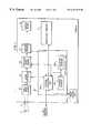
- FIG. 1is a block diagram of a digital camera in accordance with the present invention with the necessary electronics for operating the camera and having a microfluidic printer;
- FIG. 2is a side showing a user viewing the delivery chambers of the printer prior to printing an image
- FIG. 3is a partial schematic view showing a printer for pumping, mixing and printing pixels of ink onto a reflective receiver
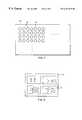
- FIG. 4is a top view of the colorant delivery chambers in the printer of FIG. 3;
- FIG. 5shows a receiver sheet having multiple different images printed on it.
- FIG. 3a schematic diagram is shown of a printer 8 in accordance with the present invention.
- Reservoirs 11 , 12 , 13 , and 14are respectively provided for holding colorless ink, cyan ink, magenta ink, and yellow ink. These reservoirs are actually provided by ink cartridges which are insertable into the printer 8 of the camera.
- a reservoir 16is shown for black ink.
- Microchannel capillaries 17respectively connected to each of the reservoirs conduct ink from the corresponding reservoir to an array of ink delivery chambers 18 .
- the ink delivery chambers 18deliver the ink directly to a receiver 19 a; however, other types of ink delivery arrangements can be used such as microfluidic channels, and so when the word chamber is described, it will be understood to include those arrangements.
- the colored inksare delivered to ink delivery chambers 18 by electrokinetic pumps 19 .
- the amount of each color inkis controlled by logic and control unit 32 according to a stored digital image. For clarity of illustration, only one electrokinetic pump 19 is shown for the colorless ink channel. Similar pumps are used for the other color channels, but these are omitted from the figure for clarity.
- a receiver 19 ais transported by a transport mechanism to come in contact with the microfluidic printer 8 . The receiver 19 a accepts the ink and thereby produce the print.
- FIG. 4depicts a top view of an arrangement of delivery chambers 18 shown in FIG. 3 .
- Each ink delivery chamber 18is capable of producing a mixture of inks of different colors having any color saturation, hue, and lightness within the color gamut provided by the set of inks used in the apparatus. This results in a continuous tone photographic quality image on the reflective receiver 19 a.
- a logic and control unit 32which receives a digital image.
- the digital imageincludes a number of digital pixels which represents a continuous tone colored image.
- the logic and control unit 32is connected to the electrokinetic pump 19 and controls its operation.
- the logic and control unit 32causes the pump to meter the correct amount of inks into each of the ink delivery chambers 18 to provide both the correct hue and tone scale for each colored pixel.
- Another function of the logic and control unit 32is to arrange the array of image pixels in the proper order so the image will be right reading to the viewer.
- the logic and control unit 32includes a matrix, or look-up table, which is determined experimentally, of all the colors which can be achieved by varying the mixture of inks. When a data for a particular pixel (8 bits per color plane) is inputted, the output from the look-up table will control signals to the electrokinetic pumps 19 to meter out the correct amount of each ink.
- a transport mechanism 15which is adapted to move the receiver 19 a into and out of engagement with the ink delivery chambers 18 under the control of the logic and control unit 32 . After the ink delivery chambers 18 have the appropriate amount of mixed ink, the logic and control unit 32 signals the transport mechanism 15 to move the receiver 19 a into engagement with the ink delivery chambers 18 for ink transfer.
- the colored inks used in this inventionare dispersions of colorants in common solvents. Examples of such inks are found is U.S. Pat. No. 5,611,847 by Gustina, Santilli, and Bugner. Inks are also be found in the following commonly assigned U.S. patent application Ser. No. 08/699,955 filed Aug. 20, 1996 entitled “Cyan and Magenta Pigment Set”; U.S. patent application Ser. No. 08/699,962 filed Aug. 20, 1996 entitled “Magenta Ink Jet Pigment Set”; U.S. patent application Ser. No. 08/699,963 filed Aug.
- the solventis water.
- Colorantssuch as the Ciba Geigy Unisperse Rubine 4BA-PA, Unisperse Yellow RT-PA, and Unisperse Blue GT-PA are also preferred embodiments of the invention.
- the colorless ink of this inventioncan take a number of different forms, which will suggest themselves to those skilled in the art. If the colored inks are water soluble, then the colorless ink can indeed be water.
- the reflective receiver 19 acan be common paper having sufficient fibers to provide a capillary force to draw the ink from the ink delivery chambers 18 into the paper. Synthetic papers can also be used.
- the receiver 19 acan have a coated layer of polymer which has a strong affinity, or mordanting effect for the inks.
- the colorless inkcan be water, which also acts as a solvent, and a layer of gelatin will provide an absorbing layer for these mixed inks.
- an exemplary reflective receiveris disclosed in commonly assigned U.S. Pat. No. 5,605,750 to Romano et al.
- FIG. 1a block diagram is shown of various systems within the camera 1 .
- a subject Sis positioned in front of the imaging lens 3 .
- the camera 1includes an area image sensor 20 arranged to coincide with the axis of the imaging lens 3 .
- the printer 8has been discussed.
- An image of the subjectis focused on the area image sensor 20 .
- Area image sensor 20can be a full frame charge coupled device (CCD) or, alternatively, can be an interline device with, for example, photodiode pixels which are adapted to deliver charge to interline CCDs.
- Conventional electronic circuitry(not shown) is associated with the image sensor 20 . After the image sensor 20 receives light representative of the image of the subject S, the circuitry sets up, acquires, and transfers electronic signals from the area image sensor 20 .
- Such electronicsare well known in the art and their description is omitted for clarity of discussion.
- Logic and control unit 32causes the area image sensor 20 to transfer electrical signals to signal processor 34 .
- the signal processor 34will be understood to include that circuitry necessary for converting the area image sensor signals to electrical signals and includes gain control and analog-to-digital circuitry as well known in the art.
- the logic and control unit 32can, of course, include a microprocessor as is well known to those skilled in the art.
- the signal processor 34delivers, under the control of logic and control unit 32 , signals into a storage location in a temporary image memory 35 which can be either a floppy disk or semiconductor memory under the control of logic and control unit 32 . These signals, when stored, represent a digital image of the subject.
- the logic and control unit 32causes the digital signals in memory to be applied to a display driver 37 which, in turn, applies signals to a display device 38 .
- the display driver 37will be understood to include a digital-to-analog converter and formatting control which is appropriate for the type of display device as well known in the art.
- the display device 38may be embodied as a liquid crystal display.
- the logical and control unit 32provides refresh signals to the display device 38 . It will be understood that the logic and control unit 32 can also deliver the digital image to an external device such as a personal computer.
- the logic and control unit 32is shown to include a central processing unit 32 a which may be provided by a microprocessor chip.
- Execution memory 32 bis also shown and is typically provided by random access memory (RAM). This memory is used for computation during image adjustment of the various parameters.
- the program memory 32 ctypically ROM
- a mode control unit 32 dincluding a keyboard, a manual switch or a combination of both, permits a user to select the appropriate program by directly inputting interrupt signals into the central processing unit 32 a.
- the usermay indicate the selection of a lower resolution image to be printed by manipulating mode control unit 32 d.
- This selectioncauses logic and control unit 32 to operate the electrokinetic pumps 19 in a manner which leaves some ink colorant delivery chambers 18 void of any colorant.
- Those ink colorant delivery chambers 18 which receive inkare simultaneously caused to receive proportionately more ink thus filling more of the image area to be printed with similar image data.
- the number of pixelsare actually reduced and the resolution also reduced without changing the image size. In such a situation, an image on a receiver 19 a can be printed faster than when the full number of pixels are printed.
- the number of ink colorant delivery chambers 18can be greater than the number of desired pixels in an image.
- the size of a printed imagecan be reduced from a full size image by not using some of the ink colorant delivery chambers 18 .
- the number of printed pixelsis less than the full size number of ink colorant delivery chambers 18
- multiple images of the same digital imagecan be printed.
- multiple different images 42can be printed on the same receiver 19 a (see FIG. 5 ).
- the usermay indicate that a monochromatic rendering of the image is preferred again by using the mode control unit 32 d.
- logic and control unit 32causes the operation of electrokinetic pumps 19 to selectively draw ink from a single reservoir in accordance with the selection of the user by operation of mode control unit 32 d.
- continuous tone imageswill include not only continuous tone images recorded from nature, but also computer generated images, graphic images, line art, text images and the like.
- colorless inkrefers to colorless or white fluids that do not absorb visible light when the colorless ink is transferred to a reflective receiver.
- the logic and control unit 32receives a digital image or digital image file consisting of electronic signals in which the color code values are characterized by bit depths of an essentially continuous tone image, for example, 8 bits per color per pixel. Based on the color code values at each pixel in the digital image, which define the lightness, hue, and color saturation at the pixel, logic and control unit 32 operates the electrokinetic pumps 19 to mix the appropriate amount of colored inks and colorless inks in the array of ink colorant delivery chambers 18 . Stated differently, the corresponding mixed inks in each chamber 18 are in an amount corresponding to a code value for a digital colored pixel.
- the mixture of inkswhich has the same hue, lightness, and color saturation as the corresponding pixel of the original image being printed, is held in the colorant delivery chamber by the surface tension of the ink.
- the reflective receiver 19 ais subsequently placed by the transport mechanism 15 under the control of the logic and control unit 32 in contact with the ink meniscus of the ink colorant delivery chamber 18 within the printer front plate 40 .
- the mixture of inks contained in the colorant delivery chamber 18is then drawn into the reflective receiver 19 a by the capillary force of the paper fibers, or by the absorbing or mordanting force of the polymeric layer coated on the reflective receiver 19 a.
- the receiver 19 ais peeled away from the ink colorant delivery chamber 18 in the printer front plate immediately after the time required to reach the full density of the print.
- the receiver 19 acannot be left in contact with the front plate for too long a time or the density of the print will be higher than desired.
- One important advantage of the present inventionis the reduction of the printing image defects that commonly occur when the cyan, magenta, and yellow inks are printed in separate operations. Misregistration of the apparatus often leads to visible misregistration of the color planes being printed. In this invention, all the color planes are printed simultaneously, thus eliminating such misregistration.
- Ink from the black ink reservoir 16can be included in the colored in mixtures to improve the density of dark areas of the print, or can be used alone to print text, or line art, if such is included in the image being printed.
- FIG. 2is a side view showing a user viewing the rear side of delivery chambers 18
- the microfluidic printer 8also performs the function of a display prior to printing.
- the construction of the printer 8is such that a user can view the reverse side of the delivery chambers 18 .
- the delivery chambers 18are fabricated in a glass member so that they can be readily observed by a user. In this way, the printer also displays an image to be printed. This is disclosed in the above referenced U.S. patent application Ser. No. 08/882,620 filed Jun. 25, 1997.
- a receiver 19 ais arranged to contact the chambers and to draw ink from such chambers by capillary action.
Landscapes
- Engineering & Computer Science (AREA)
- Multimedia (AREA)
- Signal Processing (AREA)
- Human Computer Interaction (AREA)
- Ink Jet (AREA)
Abstract
Description
Claims (9)
Priority Applications (1)
| Application Number | Priority Date | Filing Date | Title |
|---|---|---|---|
| US08/951,017US6191815B1 (en) | 1997-10-15 | 1997-10-15 | Camera with microfluidic printer |
Applications Claiming Priority (1)
| Application Number | Priority Date | Filing Date | Title |
|---|---|---|---|
| US08/951,017US6191815B1 (en) | 1997-10-15 | 1997-10-15 | Camera with microfluidic printer |
Publications (1)
| Publication Number | Publication Date |
|---|---|
| US6191815B1true US6191815B1 (en) | 2001-02-20 |
Family
ID=25491159
Family Applications (1)
| Application Number | Title | Priority Date | Filing Date |
|---|---|---|---|
| US08/951,017Expired - LifetimeUS6191815B1 (en) | 1997-10-15 | 1997-10-15 | Camera with microfluidic printer |
Country Status (1)
| Country | Link |
|---|---|
| US (1) | US6191815B1 (en) |
Cited By (8)
| Publication number | Priority date | Publication date | Assignee | Title |
|---|---|---|---|---|
| US20040184788A1 (en)* | 1997-11-05 | 2004-09-23 | Nikon Corporation | Information processing device, method of controlling information processing device, and recording medium |
| US20050146615A1 (en)* | 1999-06-30 | 2005-07-07 | Kia Silverbrook | Digital camera with interactive printer |
| US20050202804A1 (en)* | 1999-06-30 | 2005-09-15 | Silverbrook Research Pty Ltd | Method of using a mobile device to authenticate a printed token and output an image associated with the token |
| US20060025116A1 (en)* | 1999-06-30 | 2006-02-02 | Silverbrook Research Pty Ltd | Retrieving an image via a coded surface |
| US6999113B1 (en)* | 1998-10-22 | 2006-02-14 | Fuji Photo Film Co., Ltd. | Portable printer and camera |
| US7411608B1 (en) | 2004-08-20 | 2008-08-12 | Raymond Wayne Moskaluk | System and method for producing photographic prints |
| US20090296139A1 (en)* | 2002-09-20 | 2009-12-03 | Seiko Epson Corporation | Selection of image data for output |
| US20110069354A1 (en)* | 1999-06-30 | 2011-03-24 | Silverbrook Research Pty Ltd | Printing system utilizing cartridge pre-stored with identifiers with identifying printed pages |
Citations (5)
| Publication number | Priority date | Publication date | Assignee | Title |
|---|---|---|---|---|
| US4262301A (en)* | 1978-03-30 | 1981-04-14 | Polaroid Corporation | Electronic imaging camera |
| US5715234A (en)* | 1996-12-16 | 1998-02-03 | Eastman Kodak Company | Electronic camera and associated printer which uses a display image |
| US5751445A (en)* | 1991-11-11 | 1998-05-12 | Canon Kk | Image transmission system and terminal device |
| US5771810A (en)* | 1997-06-25 | 1998-06-30 | Eastman Kodak Company | Continuous tone microfluidic display and printing |
| US5894326A (en)* | 1996-08-26 | 1999-04-13 | Eastman Kodak Company | Electronic camera having a printer |
- 1997
- 1997-10-15USUS08/951,017patent/US6191815B1/ennot_activeExpired - Lifetime
Patent Citations (5)
| Publication number | Priority date | Publication date | Assignee | Title |
|---|---|---|---|---|
| US4262301A (en)* | 1978-03-30 | 1981-04-14 | Polaroid Corporation | Electronic imaging camera |
| US5751445A (en)* | 1991-11-11 | 1998-05-12 | Canon Kk | Image transmission system and terminal device |
| US5894326A (en)* | 1996-08-26 | 1999-04-13 | Eastman Kodak Company | Electronic camera having a printer |
| US5715234A (en)* | 1996-12-16 | 1998-02-03 | Eastman Kodak Company | Electronic camera and associated printer which uses a display image |
| US5771810A (en)* | 1997-06-25 | 1998-06-30 | Eastman Kodak Company | Continuous tone microfluidic display and printing |
Cited By (27)
| Publication number | Priority date | Publication date | Assignee | Title |
|---|---|---|---|---|
| US7929019B2 (en) | 1997-11-05 | 2011-04-19 | Nikon Corporation | Electronic handheld camera with print mode menu for setting printing modes to print to paper |
| US20100271493A1 (en)* | 1997-11-05 | 2010-10-28 | Nikon Corporation | Information processing device, method of controlling information processing device, and recording medium |
| US20040184788A1 (en)* | 1997-11-05 | 2004-09-23 | Nikon Corporation | Information processing device, method of controlling information processing device, and recording medium |
| US6999113B1 (en)* | 1998-10-22 | 2006-02-14 | Fuji Photo Film Co., Ltd. | Portable printer and camera |
| US20100046030A1 (en)* | 1999-06-30 | 2010-02-25 | Silverbrook Research Pty Ltd | Method of Performing an Action Using a Printed Medium |
| US7792298B2 (en) | 1999-06-30 | 2010-09-07 | Silverbrook Research Pty Ltd | Method of using a mobile device to authenticate a printed token and output an image associated with the token |
| US20080252735A1 (en)* | 1999-06-30 | 2008-10-16 | Silverbrook Research Pty Ltd | Camera having printer for printing interactive interfaces |
| US20080259165A1 (en)* | 1999-06-30 | 2008-10-23 | Silverbrook Research Pty Ltd | Camera having printer for printing interactive interfaces |
| US20080259166A1 (en)* | 1999-06-30 | 2008-10-23 | Silverbrook Research Pty Ltd | Camera having networked interactive printer |
| US7538793B2 (en)* | 1999-06-30 | 2009-05-26 | Silverbrook Research Pty Ltd | Digital camera with interactive printer |
| US20090231443A1 (en)* | 1999-06-30 | 2009-09-17 | Silverbrook Research Pty Ltd | Camera having networked printer |
| US8351907B2 (en) | 1999-06-30 | 2013-01-08 | Silverbrook Research Pty Ltd | Retrieving a document using a print medium having encoded print medium identifier |
| US20060025116A1 (en)* | 1999-06-30 | 2006-02-02 | Silverbrook Research Pty Ltd | Retrieving an image via a coded surface |
| US20100060744A1 (en)* | 1999-06-30 | 2010-03-11 | Silverbrook Research Pty Ltd | Camera For Capturing And Printing Images |
| US7728872B2 (en)* | 1999-06-30 | 2010-06-01 | Silverbrook Research Pty Ltd | Digital camera with interactive printer |
| US8274569B2 (en) | 1999-06-30 | 2012-09-25 | Silverbrook Research Pty Ltd | Printing system utilizing cartridge pre-stored with identifiers with identifying printed pages |
| US7817989B2 (en) | 1999-06-30 | 2010-10-19 | Silverbrook Research Pty Ltd | Method of performing an action using a printed medium |
| US20050202804A1 (en)* | 1999-06-30 | 2005-09-15 | Silverbrook Research Pty Ltd | Method of using a mobile device to authenticate a printed token and output an image associated with the token |
| US7831244B2 (en) | 1999-06-30 | 2010-11-09 | Silverbrook Research Pty Ltd | Retrieving an image via a coded surface |
| US7834906B2 (en) | 1999-06-30 | 2010-11-16 | Silverbrook Research Pty Ltd | Camera having printer for printing interactive interfaces |
| US20100328701A1 (en)* | 1999-06-30 | 2010-12-30 | Silverbrook Research Pty Ltd. | Performing an Action Using a Printed Medium |
| US20110069354A1 (en)* | 1999-06-30 | 2011-03-24 | Silverbrook Research Pty Ltd | Printing system utilizing cartridge pre-stored with identifiers with identifying printed pages |
| US7920166B2 (en) | 1999-06-30 | 2011-04-05 | Silverbrook Research Pty Ltd | Camera having coded data interactive printer |
| US20050146615A1 (en)* | 1999-06-30 | 2005-07-07 | Kia Silverbrook | Digital camera with interactive printer |
| US8009196B2 (en) | 1999-06-30 | 2011-08-30 | Silverbrook Research Pty Ltd | Camera having networked interactive printer |
| US20090296139A1 (en)* | 2002-09-20 | 2009-12-03 | Seiko Epson Corporation | Selection of image data for output |
| US7411608B1 (en) | 2004-08-20 | 2008-08-12 | Raymond Wayne Moskaluk | System and method for producing photographic prints |
Similar Documents
| Publication | Publication Date | Title |
|---|---|---|
| US5771810A (en) | Continuous tone microfluidic display and printing | |
| US6323912B1 (en) | Electronic camera with microfluidic printer that prints scented images | |
| DE69725043T2 (en) | Ink jet printing system, method and apparatus for ink jet printing | |
| US6037955A (en) | Microfluidic image display | |
| US6120129A (en) | Ink-jet print method and apparatus | |
| US6474799B1 (en) | Ink cartridge and a printing device using the ink cartridge | |
| US20070273917A1 (en) | Methods, Apparatus and Software for Printing Location Pattern and Printed Materials | |
| CN101234559A (en) | Printing position adjusting method, printing system and main frame device | |
| EP0627323B1 (en) | Method and apparatus for ink jet recording | |
| DE69737618T2 (en) | Apparatus and method for producing halftone recording and halftone recording of suitable ink containers and headboxes | |
| US6191815B1 (en) | Camera with microfluidic printer | |
| US6486901B1 (en) | Microfluidic printing with gel-forming inks | |
| US6042208A (en) | Image producing apparatus for microfluidic printing | |
| US6057864A (en) | Image producing apparatus for uniform microfluidic printing | |
| US6953239B2 (en) | Printer system and printing method | |
| US6072509A (en) | Microfluidic printing with ink volume control | |
| JPH09286123A (en) | Ink jet recording system and ink jet recording method | |
| US6128027A (en) | Continuous tone microfluidic printing | |
| US6055003A (en) | Continuous tone microfluidic printing | |
| US6435655B1 (en) | Color ink jet recording method/apparatus | |
| US5986678A (en) | Microfluidic printing on receiver | |
| US6139127A (en) | Ink-jet recording method for reducing white blur and recording apparatus for practicing the method | |
| US6078340A (en) | Using silver salts and reducing reagents in microfluidic printing | |
| US6091433A (en) | Contact microfluidic printing apparatus | |
| US6042209A (en) | Microfluidic printing with optical density control |
Legal Events
| Date | Code | Title | Description |
|---|---|---|---|
| AS | Assignment | Owner name:EASTMAN KODAK COMPANY, NEW YORK Free format text:ASSIGNMENT OF ASSIGNORS INTEREST;ASSIGNOR:MCINTYRE, DALE F.;REEL/FRAME:008777/0310 Effective date:19970819 | |
| FEPP | Fee payment procedure | Free format text:PAYOR NUMBER ASSIGNED (ORIGINAL EVENT CODE: ASPN); ENTITY STATUS OF PATENT OWNER: LARGE ENTITY | |
| STCF | Information on status: patent grant | Free format text:PATENTED CASE | |
| FPAY | Fee payment | Year of fee payment:4 | |
| FPAY | Fee payment | Year of fee payment:8 | |
| AS | Assignment | Owner name:CITICORP NORTH AMERICA, INC., AS AGENT, NEW YORK Free format text:SECURITY INTEREST;ASSIGNORS:EASTMAN KODAK COMPANY;PAKON, INC.;REEL/FRAME:028201/0420 Effective date:20120215 | |
| FPAY | Fee payment | Year of fee payment:12 | |
| AS | Assignment | Owner name:KODAK REALTY, INC., NEW YORK Free format text:PATENT RELEASE;ASSIGNORS:CITICORP NORTH AMERICA, INC.;WILMINGTON TRUST, NATIONAL ASSOCIATION;REEL/FRAME:029913/0001 Effective date:20130201 Owner name:KODAK (NEAR EAST), INC., NEW YORK Free format text:PATENT RELEASE;ASSIGNORS:CITICORP NORTH AMERICA, INC.;WILMINGTON TRUST, NATIONAL ASSOCIATION;REEL/FRAME:029913/0001 Effective date:20130201 Owner name:KODAK PHILIPPINES, LTD., NEW YORK Free format text:PATENT RELEASE;ASSIGNORS:CITICORP NORTH AMERICA, INC.;WILMINGTON TRUST, NATIONAL ASSOCIATION;REEL/FRAME:029913/0001 Effective date:20130201 Owner name:CREO MANUFACTURING AMERICA LLC, WYOMING Free format text:PATENT RELEASE;ASSIGNORS:CITICORP NORTH AMERICA, INC.;WILMINGTON TRUST, NATIONAL ASSOCIATION;REEL/FRAME:029913/0001 Effective date:20130201 Owner name:PAKON, INC., INDIANA Free format text:PATENT RELEASE;ASSIGNORS:CITICORP NORTH AMERICA, INC.;WILMINGTON TRUST, NATIONAL ASSOCIATION;REEL/FRAME:029913/0001 Effective date:20130201 Owner name:KODAK AVIATION LEASING LLC, NEW YORK Free format text:PATENT RELEASE;ASSIGNORS:CITICORP NORTH AMERICA, INC.;WILMINGTON TRUST, NATIONAL ASSOCIATION;REEL/FRAME:029913/0001 Effective date:20130201 Owner name:FPC INC., CALIFORNIA Free format text:PATENT RELEASE;ASSIGNORS:CITICORP NORTH AMERICA, INC.;WILMINGTON TRUST, NATIONAL ASSOCIATION;REEL/FRAME:029913/0001 Effective date:20130201 Owner name:KODAK IMAGING NETWORK, INC., CALIFORNIA Free format text:PATENT RELEASE;ASSIGNORS:CITICORP NORTH AMERICA, INC.;WILMINGTON TRUST, NATIONAL ASSOCIATION;REEL/FRAME:029913/0001 Effective date:20130201 Owner name:KODAK PORTUGUESA LIMITED, NEW YORK Free format text:PATENT RELEASE;ASSIGNORS:CITICORP NORTH AMERICA, INC.;WILMINGTON TRUST, NATIONAL ASSOCIATION;REEL/FRAME:029913/0001 Effective date:20130201 Owner name:EASTMAN KODAK COMPANY, NEW YORK Free format text:PATENT RELEASE;ASSIGNORS:CITICORP NORTH AMERICA, INC.;WILMINGTON TRUST, NATIONAL ASSOCIATION;REEL/FRAME:029913/0001 Effective date:20130201 Owner name:QUALEX INC., NORTH CAROLINA Free format text:PATENT RELEASE;ASSIGNORS:CITICORP NORTH AMERICA, INC.;WILMINGTON TRUST, NATIONAL ASSOCIATION;REEL/FRAME:029913/0001 Effective date:20130201 Owner name:LASER-PACIFIC MEDIA CORPORATION, NEW YORK Free format text:PATENT RELEASE;ASSIGNORS:CITICORP NORTH AMERICA, INC.;WILMINGTON TRUST, NATIONAL ASSOCIATION;REEL/FRAME:029913/0001 Effective date:20130201 Owner name:KODAK AMERICAS, LTD., NEW YORK Free format text:PATENT RELEASE;ASSIGNORS:CITICORP NORTH AMERICA, INC.;WILMINGTON TRUST, NATIONAL ASSOCIATION;REEL/FRAME:029913/0001 Effective date:20130201 Owner name:FAR EAST DEVELOPMENT LTD., NEW YORK Free format text:PATENT RELEASE;ASSIGNORS:CITICORP NORTH AMERICA, INC.;WILMINGTON TRUST, NATIONAL ASSOCIATION;REEL/FRAME:029913/0001 Effective date:20130201 Owner name:NPEC INC., NEW YORK Free format text:PATENT RELEASE;ASSIGNORS:CITICORP NORTH AMERICA, INC.;WILMINGTON TRUST, NATIONAL ASSOCIATION;REEL/FRAME:029913/0001 Effective date:20130201 Owner name:EASTMAN KODAK INTERNATIONAL CAPITAL COMPANY, INC., Free format text:PATENT RELEASE;ASSIGNORS:CITICORP NORTH AMERICA, INC.;WILMINGTON TRUST, NATIONAL ASSOCIATION;REEL/FRAME:029913/0001 Effective date:20130201 | |
| AS | Assignment | Owner name:INTELLECTUAL VENTURES FUND 83 LLC, NEVADA Free format text:ASSIGNMENT OF ASSIGNORS INTEREST;ASSIGNOR:EASTMAN KODAK COMPANY;REEL/FRAME:030269/0001 Effective date:20130201 | |
| AS | Assignment | Owner name:MONUMENT PEAK VENTURES, LLC, TEXAS Free format text:ASSIGNMENT OF ASSIGNORS INTEREST;ASSIGNOR:INTELLECTUAL VENTURES FUND 83 LLC;REEL/FRAME:041941/0079 Effective date:20170215 | |
| AS | Assignment | Owner name:MONUMENT PEAK VENTURES, LLC, TEXAS Free format text:RELEASE BY SECURED PARTY;ASSIGNOR:INTELLECTUAL VENTURES FUND 83 LLC;REEL/FRAME:064599/0304 Effective date:20230728 |