US6190357B1 - Expandable cannula for performing cardiopulmonary bypass and method for using same - Google Patents
Expandable cannula for performing cardiopulmonary bypass and method for using sameDownload PDFInfo
- Publication number
- US6190357B1 US6190357B1US09/063,588US6358898AUS6190357B1US 6190357 B1US6190357 B1US 6190357B1US 6358898 AUS6358898 AUS 6358898AUS 6190357 B1US6190357 B1US 6190357B1
- Authority
- US
- United States
- Prior art keywords
- cannula
- elongate body
- lumen
- tubular elongate
- diameter
- Prior art date
- Legal status (The legal status is an assumption and is not a legal conclusion. Google has not performed a legal analysis and makes no representation as to the accuracy of the status listed.)
- Expired - Fee Related
Links
- 230000002612cardiopulmonary effectEffects0.000titleclaimsdescription6
- 238000000034methodMethods0.000titleabstractdescription54
- 230000010412perfusionEffects0.000claimsabstractdescription70
- 239000012530fluidSubstances0.000claimsabstractdescription33
- 230000006870functionEffects0.000claimsabstractdescription24
- 238000001356surgical procedureMethods0.000claimsabstractdescription13
- 238000004891communicationMethods0.000claimsabstractdescription9
- 238000003780insertionMethods0.000claimsdescription47
- 230000037431insertionEffects0.000claimsdescription47
- 238000013022ventingMethods0.000claimsdescription13
- 210000004369bloodAnatomy0.000abstractdescription38
- 239000008280bloodSubstances0.000abstractdescription38
- 210000000709aortaAnatomy0.000description40
- 210000002216heartAnatomy0.000description33
- 210000002376aorta thoracicAnatomy0.000description24
- 210000001105femoral arteryAnatomy0.000description21
- 239000000463materialSubstances0.000description16
- 238000011144upstream manufacturingMethods0.000description13
- 238000003384imaging methodMethods0.000description12
- 210000001765aortic valveAnatomy0.000description11
- 238000013461designMethods0.000description11
- 210000003270subclavian arteryAnatomy0.000description11
- FAPWRFPIFSIZLT-UHFFFAOYSA-MSodium chlorideChemical compound[Na+].[Cl-]FAPWRFPIFSIZLT-UHFFFAOYSA-M0.000description10
- 230000017531blood circulationEffects0.000description10
- 210000001367arteryAnatomy0.000description9
- 239000011780sodium chlorideSubstances0.000description9
- 238000012544monitoring processMethods0.000description8
- 230000006378damageEffects0.000description7
- 208000014674injuryDiseases0.000description7
- 230000008733traumaEffects0.000description7
- 210000004351coronary vesselAnatomy0.000description6
- 210000003462veinAnatomy0.000description6
- 210000002620vena cava superiorAnatomy0.000description6
- 102400001284Vessel dilatorHuman genes0.000description5
- 108010090012atrial natriuretic factor prohormone (31-67)Proteins0.000description5
- 238000010276constructionMethods0.000description5
- 230000023597hemostasisEffects0.000description5
- 210000004115mitral valveAnatomy0.000description5
- 230000037361pathwayEffects0.000description5
- 229920003023plasticPolymers0.000description5
- 239000004033plasticSubstances0.000description5
- 239000005020polyethylene terephthalateSubstances0.000description5
- 229920002635polyurethanePolymers0.000description5
- 239000004814polyurethaneSubstances0.000description5
- 210000001631vena cava inferiorAnatomy0.000description5
- CURLTUGMZLYLDI-UHFFFAOYSA-NCarbon dioxideChemical compoundO=C=OCURLTUGMZLYLDI-UHFFFAOYSA-N0.000description4
- 210000002168brachiocephalic trunkAnatomy0.000description4
- 230000008602contractionEffects0.000description4
- 210000003191femoral veinAnatomy0.000description4
- 210000004731jugular veinAnatomy0.000description4
- 230000002093peripheral effectEffects0.000description4
- 229920000139polyethylene terephthalatePolymers0.000description4
- 230000008439repair processEffects0.000description4
- 210000005245right atriumAnatomy0.000description4
- 210000001519tissueAnatomy0.000description4
- 208000031481Pathologic ConstrictionDiseases0.000description3
- 210000000702aorta abdominalAnatomy0.000description3
- 238000013459approachMethods0.000description3
- 210000004204blood vesselAnatomy0.000description3
- 210000004556brainAnatomy0.000description3
- 230000032798delaminationEffects0.000description3
- 239000004744fabricSubstances0.000description3
- 210000002837heart atriumAnatomy0.000description3
- -1polyethylenePolymers0.000description3
- 238000010926purgeMethods0.000description3
- 230000002829reductive effectEffects0.000description3
- 230000036262stenosisEffects0.000description3
- 208000037804stenosisDiseases0.000description3
- 230000000153supplemental effectEffects0.000description3
- 210000005166vasculatureAnatomy0.000description3
- 206010058178Aortic occlusionDiseases0.000description2
- 208000004434CalcinosisDiseases0.000description2
- 208000005189EmbolismDiseases0.000description2
- 239000004698PolyethyleneSubstances0.000description2
- 206010067171RegurgitationDiseases0.000description2
- 238000009825accumulationMethods0.000description2
- QVGXLLKOCUKJST-UHFFFAOYSA-Natomic oxygenChemical compound[O]QVGXLLKOCUKJST-UHFFFAOYSA-N0.000description2
- 230000008901benefitEffects0.000description2
- 210000000601blood cellAnatomy0.000description2
- 229910002092carbon dioxideInorganic materials0.000description2
- 239000001569carbon dioxideSubstances0.000description2
- 238000007675cardiac surgeryMethods0.000description2
- 208000029078coronary artery diseaseDiseases0.000description2
- 210000003748coronary sinusAnatomy0.000description2
- 230000003073embolic effectEffects0.000description2
- 210000003743erythrocyteAnatomy0.000description2
- 239000007789gasSubstances0.000description2
- 210000003709heart valveAnatomy0.000description2
- 208000018578heart valve diseaseDiseases0.000description2
- 238000001802infusionMethods0.000description2
- 210000002414legAnatomy0.000description2
- 239000004620low density foamSubstances0.000description2
- 210000004379membraneAnatomy0.000description2
- 239000012528membraneSubstances0.000description2
- 229910052751metalInorganic materials0.000description2
- 239000002184metalSubstances0.000description2
- 208000010125myocardial infarctionDiseases0.000description2
- 210000004165myocardiumAnatomy0.000description2
- 229910052760oxygenInorganic materials0.000description2
- 239000001301oxygenSubstances0.000description2
- 230000000149penetrating effectEffects0.000description2
- 229920000573polyethylenePolymers0.000description2
- 239000004800polyvinyl chlorideSubstances0.000description2
- 238000002360preparation methodMethods0.000description2
- 238000011084recoveryMethods0.000description2
- 239000000243solutionSubstances0.000description2
- 230000002966stenotic effectEffects0.000description2
- 210000001321subclavian veinAnatomy0.000description2
- 206010053567CoagulopathiesDiseases0.000description1
- 206010010356Congenital anomalyDiseases0.000description1
- 229920004934Dacron®Polymers0.000description1
- FYYHWMGAXLPEAU-UHFFFAOYSA-NMagnesiumChemical compound[Mg]FYYHWMGAXLPEAU-UHFFFAOYSA-N0.000description1
- 241001272720Medialuna californiensisSpecies0.000description1
- 206010035148PlagueDiseases0.000description1
- 208000035965Postoperative ComplicationsDiseases0.000description1
- ZLMJMSJWJFRBEC-UHFFFAOYSA-NPotassiumChemical compound[K]ZLMJMSJWJFRBEC-UHFFFAOYSA-N0.000description1
- 241000607479Yersinia pestisSpecies0.000description1
- 230000003187abdominal effectEffects0.000description1
- 230000001154acute effectEffects0.000description1
- 230000008321arterial blood flowEffects0.000description1
- 230000004872arterial blood pressureEffects0.000description1
- 238000010009beatingMethods0.000description1
- 230000036772blood pressureEffects0.000description1
- 230000000747cardiac effectEffects0.000description1
- 229940100084cardioplegia solutionDrugs0.000description1
- 230000001101cardioplegic effectEffects0.000description1
- 239000008148cardioplegic solutionSubstances0.000description1
- 210000001715carotid arteryAnatomy0.000description1
- 230000004087circulationEffects0.000description1
- 230000035602clottingEffects0.000description1
- 229920006037cross link polymerPolymers0.000description1
- 230000007423decreaseEffects0.000description1
- 230000003247decreasing effectEffects0.000description1
- 230000007547defectEffects0.000description1
- 230000010339dilationEffects0.000description1
- 238000002224dissectionMethods0.000description1
- 230000009977dual effectEffects0.000description1
- 238000005516engineering processMethods0.000description1
- 239000005038ethylene vinyl acetateSubstances0.000description1
- 239000006260foamSubstances0.000description1
- 230000005251gamma rayEffects0.000description1
- 239000008246gaseous mixtureSubstances0.000description1
- 230000005484gravityEffects0.000description1
- 210000004013groinAnatomy0.000description1
- 208000019622heart diseaseDiseases0.000description1
- 230000002439hemostatic effectEffects0.000description1
- 230000001184hypocalcaemic effectEffects0.000description1
- 210000003090iliac arteryAnatomy0.000description1
- 208000015181infectious diseaseDiseases0.000description1
- 230000000977initiatory effectEffects0.000description1
- 201000010849intracranial embolismDiseases0.000description1
- 239000004816latexSubstances0.000description1
- 229920000126latexPolymers0.000description1
- 210000005240left ventricleAnatomy0.000description1
- 210000003141lower extremityAnatomy0.000description1
- 210000004072lungAnatomy0.000description1
- 229910052749magnesiumInorganic materials0.000description1
- 239000011777magnesiumSubstances0.000description1
- 238000012423maintenanceMethods0.000description1
- 238000013508migrationMethods0.000description1
- 230000005012migrationEffects0.000description1
- 238000002324minimally invasive surgeryMethods0.000description1
- 230000002107myocardial effectEffects0.000description1
- 230000003287optical effectEffects0.000description1
- 238000012354overpressurizationMethods0.000description1
- 230000036961partial effectEffects0.000description1
- 239000002245particleSubstances0.000description1
- 210000003516pericardiumAnatomy0.000description1
- 229920000728polyesterPolymers0.000description1
- 229920000642polymerPolymers0.000description1
- 239000002861polymer materialSubstances0.000description1
- 229920001296polysiloxanePolymers0.000description1
- 229920006264polyurethane filmPolymers0.000description1
- 229920000915polyvinyl chloridePolymers0.000description1
- 230000002980postoperative effectEffects0.000description1
- 239000011591potassiumSubstances0.000description1
- 229910052700potassiumInorganic materials0.000description1
- MFDFERRIHVXMIY-UHFFFAOYSA-NprocaineChemical compoundCCN(CC)CCOC(=O)C1=CC=C(N)C=C1MFDFERRIHVXMIY-UHFFFAOYSA-N0.000description1
- 229960004919procaineDrugs0.000description1
- 230000008569processEffects0.000description1
- 230000001681protective effectEffects0.000description1
- 210000001147pulmonary arteryAnatomy0.000description1
- 230000003014reinforcing effectEffects0.000description1
- 230000002441reversible effectEffects0.000description1
- 210000005241right ventricleAnatomy0.000description1
- 238000007789sealingMethods0.000description1
- 239000010703siliconSubstances0.000description1
- 229910052710siliconInorganic materials0.000description1
- 239000007787solidSubstances0.000description1
- 238000013183transoesophageal echocardiographyMethods0.000description1
- 230000032258transportEffects0.000description1
- 230000000472traumatic effectEffects0.000description1
- 210000000689upper legAnatomy0.000description1
- 230000002792vascularEffects0.000description1
- 230000035899viabilityEffects0.000description1
- 210000001835visceraAnatomy0.000description1
- 230000000007visual effectEffects0.000description1
Images


Classifications
- A—HUMAN NECESSITIES
- A61—MEDICAL OR VETERINARY SCIENCE; HYGIENE
- A61M—DEVICES FOR INTRODUCING MEDIA INTO, OR ONTO, THE BODY; DEVICES FOR TRANSDUCING BODY MEDIA OR FOR TAKING MEDIA FROM THE BODY; DEVICES FOR PRODUCING OR ENDING SLEEP OR STUPOR
- A61M25/00—Catheters; Hollow probes
- A61M25/0021—Catheters; Hollow probes characterised by the form of the tubing
- A61M25/0023—Catheters; Hollow probes characterised by the form of the tubing by the form of the lumen, e.g. cross-section, variable diameter
- A—HUMAN NECESSITIES
- A61—MEDICAL OR VETERINARY SCIENCE; HYGIENE
- A61B—DIAGNOSIS; SURGERY; IDENTIFICATION
- A61B17/00—Surgical instruments, devices or methods
- A61B17/34—Trocars; Puncturing needles
- A61B17/3417—Details of tips or shafts, e.g. grooves, expandable, bendable; Multiple coaxial sliding cannulas, e.g. for dilating
- A61B17/3421—Cannulas
- A61B17/3439—Cannulas with means for changing the inner diameter of the cannula, e.g. expandable
- A—HUMAN NECESSITIES
- A61—MEDICAL OR VETERINARY SCIENCE; HYGIENE
- A61B—DIAGNOSIS; SURGERY; IDENTIFICATION
- A61B17/00—Surgical instruments, devices or methods
- A61B17/00234—Surgical instruments, devices or methods for minimally invasive surgery
- A61B2017/00238—Type of minimally invasive operation
- A61B2017/00243—Type of minimally invasive operation cardiac
Definitions
- This inventionrelates to devices for the occlusion of blood vessels, more particularly to the occlusion and subsequent perfusion, cardioplegia or venting of blood vessels using a cannula endovascularly inserted within the lumen of the vessel.
- the systemis well suited for occlusion and perfusion of the aortic arch or major arteries during cardiopulmonary bypass procedures.
- Cardiac surgeryoften requires that the heart be stilled during the procedure.
- An arrested heartallows the surgeon sufficient time and a stable environment on which to operate, a particular necessity for lengthy and invasive procedures such as valve replacement.
- a number of devices and procedureshave been developed to enable a physician to stop the heart long enough for a surgical procedure to be performed, and then restart the heart at the termination of the procedure.
- CPBcardiopulmonary bypass
- the venous drainage processmay involve placement of a cannula (or cannulae) into the right side of the heart (typically the right atrium), or directly in the major veins (typically the superior vena cava (SVC) and/or inferior vena cava (IVC) or through peripheral vein access sites.
- a cannulaor cannulae
- SVCsuperior vena cava
- IVCinferior vena cava
- An arterial or aortic perfusion cannulais placed in the aorta or another large peripheral artery, such as the common femoral artery, to return oxygenated blood to the patient.
- Cardioplegic arrest and CPBare commonly employed during cardiac surgery for treating coronary artery disease and heart valve disease.
- coronary artery diseasea buildup of stenotic plaque in the coronary arteries causes the artery to narrow or become occluded.
- the interruption of the blood flow to the heartcauses myocardial infarction, commonly known as a heart attack.
- Heart valve diseaseincludes two major categories, namely valvular stenosis, which is an obstruction to forward blood flow through the heart valve, and regurgitation, which is the retrograde leakage of blood through the heart valve.
- valvular stenosisoccurs in the aortic valve while regurgitation is typically a congenital condition affecting the mitral valve.
- a cannulawill be inserted into the patient's aortic arch.
- the insertion of the arterial (aortic) perfusion cannulais usually performed in the following fashion.
- the pericardiumthe protective sac around the heart
- two concentric purse string suturesare placed into the anterior wall of the ascending aorta just proximal to upstream side of the brachiocephalic trunk.
- a “choker” tube or sleeveis positioned over the trailing ends of the suture threads to act as a tourniquet for tightening the purse string suture.
- a small incisionis then made through the wall of the aorta in the center of the purse-string sutures.
- the aortic perfusion cannulais then quickly inserted through that incision into the aorta, taking care to minimize the escape of blood from the puncture site.
- the purse string suturesare then tightened by means of their respective tourniquets to seal the aortic wall around the perfusion cannula in order to prevent the escape of blood from the aorta.
- Airis then purged by arterial pressure from the perfusion cannula which is in fluid communication with the pump-oxygenator.
- a cross-clampis placed on the aorta just downstream of the aortic root and upstream of the cannula to ensure that no blood flows back toward the aortic valve during CPB.
- cardioplegiais administered by delivering a cardioplegic solution, such as potassium, magnesium, procaine, or a hypocalcemic solution, to the myocardium by one or a combination of two general techniques, antegrade and retrograde perfusion.
- a cardioplegic solutionsuch as potassium, magnesium, procaine, or a hypocalcemic solution
- Antegrade perfusion of cardioplegiainvolves the infusion of fluid through the coronary arteries in the normal direction of blood flow.
- a cannulais typically inserted into the aorta upstream of the aortic clamp and the solution is injected into the aortic root and delivered under pressure in the normal direction of blood flow into the coronary ostia and from there to the myocardium.
- cardioplegiais typically administered via a transverse aortotomy whereby direct access to the coronary ostia is possible.
- the cardioplegiais delivered using a wand inserted intermittently into the ostia during the procedure. Retrograde perfusion is accomplished by inserting an occlusion into the coronary sinus and administering cardioplegia upstream of the occlusion and forcing the fluid against the normal flow of the blood into the coronary veins to the myocardial capillary beds.
- the surgeonwill perform the necessary coronary procedures and repairs.
- the arterial and venous cannulawill be removed from the surgical area and the entrance sutures tightened to seal the vessel punctures.
- the placement of the occluder in the ascending aortais a particularly delicate operation as the operator must take care so as to not block the left subclavian artery, the brachiocephalic artery, or the left carotid artery, but must instead occlude the aorta just upstream of these aortic branches. Even if the placement of the occluder is proper at the initiation of the coronary repair procedure, the position of the device should be monitored closely to avoid even slight movement as the procedure continues. Movement of the device may result in partial or total closure of the aortic branches, depriving the upper body and brain of the patient of blood during the procedure.
- an endovascularly inserted cannulaemust take into account the limited space available in the body passageways used for access to the heart and other regions of interest.
- the use of multiple cannulaeincreases the number of percutaneous or direct cut-down procedures required for the procedure and increases the risk or infection and other post-operative complications. Multiple insertions also increase the risk of damage to the internal vasculature and increase the complication and time expenditure for the procedure. It would be most desirable to provide a system which would combine a multitude of functions in one device so that the need for multiple or duplicative devices can be avoided.
- the deviceshould have a minimal small cross-sectional diameter to reduce the risk of patient trauma.
- scaling and calcium depositsare common on the interior of the femoral and iliac artery and the aorta and the use of large diameter cannula increases the risk of dislodging this stenotic plaque, calcium deposits, and other material that has accumulated on the wall of the vessel.
- the problemis particularly acute when the femoral artery is accessed as the cannula is advanced against the direction of normal blood flow and consequently against the direction of scaling and accumulation of material on the arterial wall. Viability of the femoral artery may also prove to be problematic when using endovascular insertion of a cannula into the aortic arch. Vessels with an insufficient diameter for the introduction of the cannula assembly, either naturally occurring or through vessel stenosis, can prevent the use of such a system unless some alternate means of arterial or venous access to the region of interest is found.
- endovascular insertion of a cannula around 80 cm in length into a patient's vascular systemis complicated and difficult and may be rendered impossible by the bends, branches, or diseased condition of the vessels of the patient.
- a cannula system that uses alternate access pathways to the heart and other regions of interestwould be desirable.
- past procedureshave used the femoral artery, the femoral vein, and the jugular vein for coronary access because these are the only vessels with sufficient diameter to accommodate a cannula of the appropriate diameter for cardiac repair and other procedures.
- both endovascular and transvascular insertion of the cannulawould be possible.
- the systemwould preferably allow multiple functions within a single device to limit obstruction of the surgical field and reduce patient trauma and procedure time.
- the deviceshould also preferably be of a size which would allow use in multiple venous and arterial access sites.
- a cannulacomprising a flexible, expandable tubular elongate body wherein the tubular elongate body is expandable from a first diameter to a second diameter.
- the cannulais introduced into a body passageway having a first diameter and is then expanded to a second diameter in order to provide better fluid flow into the body passageway.
- a perfusion lumenis provided within the expandable tubular elongate body with at least one arterial return aperture provided within the tubular elongate body in fluid communication with the perfusion lumen.
- the cannulamay also include an expandable member fixed at the distal end of the tubular elongate body.
- the expandable memberis configured to occlude the body passageway when expanded in order to provide a clear surgical field upstream of the occlusion or a sealed chamber in which to inject the cardioplegia fluid.
- the expandable membermay be configured from polyurethane, PVC, PET or other similar materials.
- the expandable memberis an inflatable while in another, the expandable member is a low density foam about which is disposed a fluid impermeable membrane fixing the expandable member to the distal end of the cannula.
- the device of the present inventionmay include an inflation lumen for an expandable member, a multi-purpose lumen for imaging, cardioplegia, venting, or guidewire and tool access to the vessel lumen, a pressure monitoring lumen for pressure monitoring of the vessel, or a dedicated cardioplegia lumen.
- a preferred embodiment of the present inventionis configured having an inner tubular elongate body, an outer expandable tubular elongate body expandable from a first to a second diameter, wherein the outer tubular elongate body substantially disposed about the inner tubular elongate body, the inner tubular elongate body and the outer tubular elongate body cooperating to form a perfusion lumen therebetween.
- the inner tubular elongate bodyis configured having one or more lumens therein to provide cardioplegia, venting, tool access, and other functions to the vessel lumen.
- the main perfusion lumenalso includes at least one arterial return aperture provided in the outer expandable tubular elongate body.
- a preferred embodimentincludes an expandable member disposed at the distal end of the cannula for occlusion of the vessel lumen.
- a preferred embodimentincludes means for expanding the outer expandable tubular elongate body from the first diameter to the second diameter.
- Such meansinclude disposing the expandable tubular elongate body within a sheath during insertion of the cannula in a first diameter and then removing the sheath to expand the cannula to a second diameter.
- Additional expansion meansinclude subjecting the perfusion lumen to a vacuum source during insertion of the device and removing the vacuum prior to providing perfusion flow to the vessel or fastening the expandable outer tubular elongate body on itself during insertion.
- the arterial return aperturesinclude a one-way valve to allow the maintenance of a vacuum on the perfusion lumen while allowing subsequent perfusion of the vessel lumen.
- Another preferred embodiment of the present inventionis configured having walls of varying thickness so that the outer tubular elongate body is more readily collapsible at the circumferential locations having a thinner wall thickness.
- a designprovides a cannula having a decreased diameter and an increased column strength which allows unaided endovascular insertion of the contracted cannula.
- a method of occluding a vessel passage and subsequently providing fluid flow to the passagecomprising making a percutaneous incision in the vessel to be accessed, inserting an expandable cannula into the body passageway, advancing the cannula to a region of interest in the body passageway, expanding the tubular elongate body of the expandable cannula to a second diameter greater than the first diameter, and providing fluid flow to the perfusion lumen of the expandable cannula which is in fluid communication with the vessel lumen.
- fluid flow to the vesselis terminated and the cannula is removed, allowing the percutaneous incision to be closed.
- the expandable cannulamay also be contracted to a first diameter prior to removal of the cannula to aid in the removal of the cannula.
- Access sites suitable for application of the device and methods of the present inventioninclude the right and left femoral arteries, the aortic arch, the right and left subclavian, abdominal aorta access, access via either atrium through the mitral and aortic valves, or access through a full or mini-sternotomy.
- the regions of interest for which the device and methods of the present invention are well suitedinclude the venous and arterial vessels of the heart, including the jugular veins, SVC, IVC, right atrium, and aortic arch, the mitral and aortic valves of the heart, and the peripheral vessels of the heart.
- an expandable memberis expanded to occlude the body passageway upstream of the arterial return flow provided to the body passageway. Upon completion of the surgical procedure, the expandable member is contracted sufficiently to allow removal of the expandable cannula from the body passageway.
- Additional steps of the present inventionare also disclosed, including providing cardioplegia fluid to the body passage through a cardioplegia lumen provided within the expandable cannula; inserting a surgical tool into a tool lumen provided in the expandable cannula, performing a surgical procedure on the patient with the surgical tool, and removing the surgical tool; imaging the interior of the vessel lumen; and venting the vessel lumen.
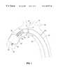
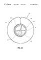
- FIG. 1is a cut-away of the aortic arch of a patient showing the device of the present invention in place in the aortic arch.
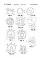
- FIG. 2is a cross-section of one embodiment of the present invention showing an alternative configuration of the internal lumen of the device.
- FIG. 3 ais a cross-section of one embodiment of the present invention showing an alternative configuration having a single lumen with the device shown expanded to a second diameter.
- FIG. 3 bis a cross-section of one embodiment of the present invention showing an alternative configuration having a single lumen with the device shown partly contracted between a first diameter and a second diameter.
- FIG. 3 cis a cross-section of one embodiment of the present invention showing an alternative configuration having a single lumen with the device shown contracted to a first diameter and contained within a sheath.
- FIG. 4 ais a cross-section of one embodiment of the present invention showing an alternative configuration having multiple lumens with the device shown contracted to a first diameter.
- FIG. 4 bis a cross-section of one embodiment of the present invention showing an alternative configuration having multiple lumens with the device shown expanding to a second diameter.
- FIG. 5is a cross-section of one embodiment of the present invention showing an alternative configuration having multiple lumens with the device shown expanded to a second diameter.
- FIG. 6is a cross-section of one embodiment of the present invention showing an alternative configuration having a centrally disposed inner tubular elongate body with multiple lumens therein.
- FIG. 7 ais a cross-section of one embodiment of the present invention showing an alternative configuration having multiple lumens with the wall of the outer tubular elongate body having thinned wall portions acting as hinge portions for contraction of the outer tubular elongate body.
- FIG. 7 bis the device of FIG. 7 a contracted to a first diameter.
- FIG. 8is a cross-section of one embodiment of the present invention showing an alternative configuration having multiple lumens centrally disposed within the outer tubular elongate body.
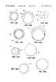
- FIG. 9 ais a configuration of the present invention wherein the outer tubular elongate body is a woven mesh material which contracts when stretched axially and expands when released.
- FIG. 9 bis an embodiment of the cannula FIG. 9 a with the expandable braided sheath in an axially stretched first diameter.
- FIG. 9 cis the proximal end of the cannula of FIG. 9 a showing a balloon occluder fully inflated and the expandable braided sheath in a relaxed second diameter
- FIG. 10is a configuration of the present invention using a sheath introducer fitted to the distal end of the expandable cannula.
- FIG. 11 ais a cross-section of one embodiment of the present invention showing a configuration having a single lumen with the wall of the outer tubular elongate body having thinned wall portions acting as hinge portions for contraction of the outer tubular elongate body.
- FIG. 11 bis a cross-section of the device of FIG. 1 la with the device shown partially expanded.
- FIG. 11 cis a cross-section of the device of FIG. 11 a with the device shown expanded to a second diameter.
- FIG. 12 ashows the vessel of a patient with a cannula introduction sheath in place in the body vessel.
- FIG. 12 bshows the vessel of a patient with a cannula introduction sheath in place in the body vessel with the expandable cannula deployed in the vessel.
- FIG. 12 cshows the vessel of a patient with a cannula introduction sheath in place in the body vessel with the expandable cannula partially withdrawn into the sheath.
- FIG. 12 dshows the vessel of a patient with a cannula introduction sheath partially removed from the body vessel.
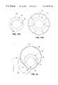
- FIG. 13 ais a cross-section of an expandable cannula showing an alternative configuration of the cannula shown contracted to a first diameter.
- FIG. 13 bis a cross-section of the device of FIG. 13 a with the outer tubular elongate body expanded to a second diameter.
- FIG. 14 ais a cross-section of an expandable cannula cannula with the device shown contracted to a first diameter.
- FIG. 14 bis a cross-section of an expandable cannula with the device shown expanded to a second diameter.
- FIG. 15 ais a cross-section of configuration of the present invention shown contracted to a first diameter.
- FIG. 15 bis a cross-section of a configuration of the present invention with the device shown expanded to a second diameter.
- FIG. 16 ais a cross-section of a configuration of the present invention with the device shown contracted to a first diameter.
- FIG. 16 bis a cross-section of a configuration of the present invention with the device shown expanded to a second diameter.
- FIG. 17 ais a cross-section of a configuration of the present invention with the device shown having an unexpanded first diameter.
- FIG. 17 bis a cross-section of a configuration of the present invention with the device shown expanded to a second diameter.
- FIG. 18is a cross-section of an alternative configuration of the present invention having a tongue and groove structure located on the outer tubular elongate body with the device shown expanded to a second diameter.
- FIG. 19 ais of a cannula of the present invention configured to be inserted into the femoral artery of the patient.
- FIG. 19 bis detail of the distal end of the cannula shown with the expandable member and expandable outer tubular elongate body fully expanded.
- FIG. 20is a cross section of the cannula showing the inner tubular elongate body and the lumens therein and the outer expandable tubular elongate body in a fully expanded configuration.
- FIG. 21is of the distal end of the cannula of FIG. 19 a showing the integrally formed lumens therein and the configuration of the distal tip of the cannula.
- FIG. 22is of the distal tip of the cannula of FIG. 21 showing the configuration of the tip.
- FIG. 23is a device used to remove air pockets from the cannula of the present invention shown with the cannula in place within the device.
- FIG. 24is the device of FIG. 23 shown detached from an introducer sheath installed in the body vessel of a patient.
- FIG. 25 ashows the device of the present invention being used to access the aortic arch via the left subclavian of the patient.
- FIG. 25 bshows the device of the present invention being used to access the aortic arch via the left subclavian of the patient and including a second cannula inserted into the right subclavian supplying additional perfusion flow to the aortic arch.
- upstream and downstreamrefer to areas closer to and farther from the heart in the arterial system, respectively. These directions are reversed when used to describe directions in the venous system of the heart.
- proximal and distalrefer to locations closer to and farther from the physician or person performing the procedure.
- FIG. 1shows one embodiment of the expandable cannula of the present invention endovascularly inserted into the aortic arch of a patient to perform CPB.
- the cannula 42comprises an expandable outer tubular elongate body 22 disposed about an inner tubular elongate body 44 .
- the internal tubular elongate bodyis provided with a tool lumen 38 and cardioplegia lumen 36 configured to provide cardioplegia to the right and left ostia of the coronary sinus.
- the tool lumen and the cardioplegia lumenmay be alternatively configured as one multi-purpose lumen or lumen 38 may be used a pressure monitoring lumen.
- the outer expandable tubular elongate bodyalso includes a number of arterial return apertures 30 for providing perfusion to the interior of the aorta 20 .
- a drainage cannulawill be introduced into the right ventricle or other venous drainage site and the de-oxygenated blood will be drained from the body to an external CPB machine (not shown).
- the CPB machinewill condition the blood, remove the carbon dioxide, and re-oxygenate the blood before returning it to the arterial system via the expandable cannula.
- the proximal end of the expandable cannulawill thus be attached to the CPB machine so that the perfusion lumen is provided with arterial blood from the machine.
- the perfusion lumenwill preferably be attached to the external source of arterial perfusion using a luer lock or other well known connection. Once the blood enters the proximal end of the perfusion lumen, it will travel through the lumen to the arterial return apertures 30 and from there into the arterial system.
- the apertures 30are preferably configured so that arterial perfusion is provided at the aortic branches first wherein the excess flow will travel down the ascending aorta and into the arterial system for the lower extremities of the body.
- inner tubular elongate body 44is also provided with an expandable member 24 which is expanded to occlude the aortic arch and insure a bloodless surgery field for a surgical procedure upstream of the expandable member 24 or a sealed chamber in which to administer cardioplegia.
- the expandable member 24is a balloon made from polyurethane or other such material.
- Polyurethaneis well suited for this application as it has some resilience and will be suited for various sized vessel lumens to fit a variety of patients and applications and allow some adjustment of the member during a surgical procedure. in some applications, it may be desirable to have an expandable member which has a maximum diameter beyond which the member will burst so as to prevent accidental dissection or damage to the aorta of the patient.
- the ballooncan be inflated with a saline fluid or other biologically acceptable fluid or gas introduced using an inflation lumen (not shown) provided within the inner tubular elongate body 44 or the outer expandable tubular elongate body 22 . In use, the balloon is preferably positioned so that it is disposed between the brachiocephalic trunk and the coronary ostia.
- FIG. 2shows one cross section of an expandable cannula embodiment.
- the cannulacomprises a inner tubular elongate body 44 which is integrally formed with the outer expandable tubular elongate body 22 .
- a number of lumenscan be integrally formed within the inner tubular elongate body 44 , including a tool lumen or pressure monitoring lumen 38 , a cardioplegia lumen 36 and an inflation lumen 46 .
- Lumen 38can also serve as a multi-function lumen for introduction of a guide wire (not shown) or other such devices, as well as venting of the vessel lumen.
- the primary consideration for the design of the cannulais to provide a means whereby the cannula can be inserted at a first diameter to a point of interest in the vessel. Once the cannula is in place, the device may then be expanded to a second diameter to provide low velocity perfusion flow to the vessel at the correct pressure. Typically, the flow rate is between 3 and 3 liters/min. at a pump pressure of about 200 mm Hg. Because the perfusion lumen 23 is contracted during insertion of the cannula, the additional available cross-sectional profile may be used for other lumens so that additional functions may be performed by the cannula 42 .
- FIG. 3( a-c ) show a single lumen expandable cannula as it is contracted from an expanded second diameter to its first diameter. Following the insertion of the cannula to a region of interest, the tubular elongate body is expanded to have a second diameter suited for providing perfusion flow to the arterial system.
- a single lumen formed within the outer tubular elongate bodymay not have sufficient column strength to allow insertion of the device into certain body vessels unaided. It may also be difficult to maintain the device in a furled or folded configuration during insertion of the member.
- an introducer sheath 58 as seen in FIGS. 12 ( a-d )may be used to augment the strength of the expandable outer elongate tubular elongate body and keep the expandable member furled in its first diameter.
- the sheath 58is configured having a tubular elongate body with a lumen therethrough for introduction of the contracted expandable cannula.
- the distal end of the sheathmay be shaped to allow easier insertion of the sheath and may include an atraumatic tip which will minimize damage from inadvertent contact with the vessel wall.
- the distal endis further configured to allow the deployment of the expandable cannula prior to providing perfusion flow to the body vessel.
- the sheathis introduced into the vessel to a point of interest and the expandable cannula is deployed from the distal end of the sheath.
- the sheath 58can be simultaneously withdrawn during deployment of the expandable cannula to eliminate movement of the cannula 42 relative to the vessel wall.
- the sheath 58may be made of any number of polymers, providing the polymer material has a durometer sufficiently high to remain semi-rigid with a thin-walled construction. Preferably it would also have a hemostatic seal at its distal end to prevent unnecessary loss of blood. Following perfusion of the vessel through the cannula, the cannula 42 is withdrawn into the sheath and the sheath 58 is removed from the body vessel.
- FIGS. 11 ( a-c )Another means of increasing the column strength of the device is seen in FIGS. 11 ( a-c ).
- the wall of the outer tubular elongate bodymay be made from a stiff, high durometer material having a number of flex points 54 located around the circumference of the body. These points have a considerably thinner wall thickness than the remainder of the body wall 55 and are consequently more readily collapsible if the body is subjected to a contracting force (i.e. an internal vacuum).
- a contracting forcei.e. an internal vacuum
- This structureoffers an advantage over other designs in that the column strength of the device can be made sufficient to allow insertion of the cannula without reinforcing structures. This eliminates the requirement to use a guidewire or stiffened support without sacrificing the required flexibility necessary to allow insertion of the cannula into the body passage.
- a guidewiremay also be used with this design as well as with the other embodiments disclosed herein to augment the column strength of the device and to aid in the insertion of the device into the vessel.
- FIG. 4 adiscloses including pressure lumens 48 and 36 , inflation lumen 46 , main perfusion lumen 23 , and tool lumen 38 .
- the cardioplegia lumenmay also double as a tool lumen, though not at the same time.
- the smallest lumensmay be used for balloon inflation and pressure monitoring. Pressure monitoring at catheter tip, distal to balloon, is most important, and a second lumen could be used to monitor the distal arterial flow pressure, as well.
- FIG. 5An alternate configuration of the cannula can be seen in FIG. 5 wherein the inner tubular elongate body includes a guidewire lumen 50 configured to allow the introduction of a flat metal guidewire to aid in the insertion of the cannula into the vessel. It must be noted that the configuration seen in FIG. 5 may be less desirable because red blood cells tend to collect and clot in small corners and nooks within a cannula.
- the connection between inner tubular elongate body 44 and outer tubular elongate body 22creates a narrow channel at that point. A narrow channel should be avoided by using a junction such as seen in FIG. 6 or FIG. 2 to prevent accumulation of blood cells in the channel and subsequent clotting.
- FIG. 7 ashows another preferred embodiment of the present invention.
- the wall of the outer tubular elongate body 22is configured in similar fashion to the previously discussed device shown in FIG. 10 and FIGS. 11 ( a-c ).
- This embodimentis further provided with a inner tubular elongate body 44 with internally formed tool/cardioplegia lumen 38 , pressure monitoring lumen 36 and inflation lumen 46 .
- additional lumensmay be provided to allow additional functions such as venting or guidewire passage.
- the relative lumen sizesmay also be varied to suit the desired application.
- the outer tubular elongate bodyis configured having a number of hinge points 54 with a thinned wall thickness so that the device tends to take the shape shown in FIG. 7 b when it is contracted to its first diameter.
- the devicemay be maintained in the first diameter either by using a vacuum on the perfusion lumen, disposing the device within an introducer sheath, fastening the device onto itself, or in some similar fashion.
- the devicewill be expanded to the second diameter once perfusion flow is desired by releasing the device to return to its natural state using the resilience of the cannula material.
- the outer tubular elongate body 22is provided with a tongue structure 90 which fits into a corresponding groove structure 94 . It is preferred that the groove structure 90 run the entire length of the cannula to eliminate potentially traumatic protuberances on the exterior of the cannula. In this configuration, the tongue 90 is inserted into the groove structure 94 prior to inserting the cannula into the vessel.
- the deviceincludes a guidewire lumen 92 having a half moon or other functionally specific shape. The guidewire is shaped so that on insertion into the guidewire lumen 92 , the guidewire exerts pressure on the groove structure to securely hold the tongue 90 in place within the groove structure 94 . When it is desired to expand the device to the second diameter, the guidewire is removed from the lumen 92 and the groove structure 94 expands and releases the tongue 90 . Perfusion may then be administered to the vessel using the now expanded perfusion lumen 23 .
- the expandable cannulacomprises a woven mesh outer tubular elongate body which compresses radially when exposed to axial expansion and expands radially when compressed axially.
- the mesh portion 49is preferably covered with a compliant fluid-impervious material which is provided with one or more perfusion openings at the distal end as in prior designs. As seen in FIG. 9 a , the mesh portion 49 may be introduced into the access site through the vessel wall 33 via an introducer sheath 47 .
- the sheathis advanced to the area of interest and the mesh portion 37 is then deployed from the distal end of the introducer sheath into the vessel lumen and allowed to return to an unstretched, axially expanded condition.
- the outer tubular elongate bodyis continuously fed through the introducer sheath 47 until the expandable cannula is in place in the vessel to be perfused.
- the cannula of FIG. 9 afurther includes a inner tubular elongate body 44 having one or more lumens therein and an expandable member 24 located near the distal end of the inner tubular elongate body 44 .
- FIGS. 9 ( b-c )An alternative embodiment of the expandable braided mesh cannula can be seen with reference to FIGS. 9 ( b-c ).
- the cannula 42is introduced into the target vessel via a percutaneous incision or a direct cut-down procedure as explained in detail below.
- the cannulais contracted by axially stretching the braided mesh sheath 37 . This can be accomplished by manually pulling the proximal end of the sheath 121 .
- Fitting 120is provided on the proximal end 121 for connection to a supply of arterial return.
- the inner tubular elongate body 44is configured having a number of lumen integrally formed within, including a pressure lumen 48 , an inflation lumen 46 , and a multi-function lumen 36 . These lumens are provided with fittings 132 , 128 , and 130 at the proximal ends, respectively.
- a guidewire 27may also be used for insertion of the cannula into the target vessel.
- FIG. 9 cshows the braided mesh sheath 37 in a fully expanded condition. This can be done by releasing the axial tension on the proximal end 121 of the cannula and allowing the sheath 37 to return to a relaxed second diameter. Perfusion flow may be provided in the expanded sheath 37 through the arterial return apertures 30 provided in the distal end of the sheath, or at other specific locations along its length. As in other embodiments, an expandable member 24 may be fixed at the distal end of the inner tubular elongate body 44 . Preferred materials for construction of the braided sheath include polyester monofilaments such as Dacron. The sheath 37 may be coated with an impermeable, flexible membrane such as silicone or polyurethane.
- the cannulahas an outer tubular elongate body having a double walled portion 66 and a single walled portion 67 .
- the single-walled portion and the double walled portioneach have a free end and are joined relative to each other so as to form a single unitary body having a substantially circular cross-section.
- the single walled portion 67is receivable in the recess 60 between the first and second walls of the double walled portion 66 . During contraction, the single walled portion is almost completely disposed within the recess 60 .
- the single wallis slidingly engaged in the recess and slides outward when the cannula is expanded to the second diameter as shown in FIG. 13 b .
- a stop 62may also be provided at the free end of the single walled portion 67 to prevent the single walled portion from being completely removed from the recess 60 during expansion of the cannula.
- the stop 62is prevented from passing beyond a narrowed portion 64 provided at the free end of the double walled portion 66 .
- creating a fluid seal between the single walled portion 67 and the recess 60may prove difficult. However, this is not a critical problem as a minor amount of leakage into the vessel will merely join the other arterial return flow that is perfused into the vessel.
- FIG. 14 ( a-b )shows an alternate configuration wherein the single walled portion 68 and the double walled portion 66 are separate structures.
- the single walled portion 68has an arcuate cross-section with the double walled portion 66 similarly shaped.
- the free ends of the single walled portion 68are inserted into a pair of recesses 70 between the first and second walls of the double walled portion 66 .
- the single walled portion 68is slidingly disposed within the recess so that the single walled portion 68 is almost fully disposed within the recess when the device is contracted to a first diameter.
- the single walled portion 68is only partially disposed within the recess 60 when the device is expanded to the second diameter.
- a stopmay cooperate with a narrowed portion of the recess 60 to prevent the single walled portion 68 from becoming disengaged from the double walled portion 66 .
- FIG. 15 aAnother embodiment of an expandable cannula is seen at FIG. 15 a .
- the wall of the tubular elongate bodyis configured having a thin walled portion 74 and a thick walled portion 76 which define an unbroken circular cross-section.
- the thin-walled portion 74is configured to be more flexible and compliant than the thick walled portion 76 .
- the thin-walled portion 74folds in on itself and the thick walled portion 76 is configured to dispose itself around the folded thin-walled portion 74 , forming a substantially circular cross-sectional configuration as shown in FIG. 15 a .
- the configuration shown in FIG. 15 aoffers a reduced diameter configuration with sufficient column strength to allow endovascular insertion of the device into the body vessel.
- FIG. 16 ( a-c )shows another configuration wherein the outer tubular elongate body is formed of a single strip 80 of flexible material that has been coiled into a circular configuration. Coiling and uncoiling of the strip 80 causes the device to expand and contract from the first diameter to a second diameter. As strip 80 uncoils, the amount of overlap between the inner and outer edges decreases. As seen in FIG. 16 c one of the edges may be scalloped, castellated or otherwise notched. As the second diameter is approached, these notches are revealed, allowing escape of blood while preventing further expansion of the cannula.
- FIG. 17Yet another embodiment of an expandable cannula is seen at FIG. 17 ( a-b ).
- the outer tubular elongate body 84 that transports the arterial return bloodis formed from and becomes distinct from the inner tubular elongate body 44 by causing delamination of the outer tubular elongate body 84 from the inner tubular elongate body 44 .
- the delamination of tubular body 82 into an inner tubular elongate body 44 an outer tubular elongate body 84occurs as fluid (i.e. arterial return blood) is forced between the layers at the proximal end of the cannula.
- the cannulais preferably composed of an irradiated, cross-linked polymer that, when expanded as in the outer tubular layer 84 , expands easily to a set diameter and becomes non-elastic beyond that diameter.
- the device of the present inventioncan be manufactured in a manner similar to traditional cannula systems.
- the devices described in the foregoing embodimentsoffer a number of advantages over prior devices. It is highly desirable to have a cannula which can perform multiple functions. However, such a cannula is limited in size as it must be readily insertable into the body vessel. Larger cannulae can increase the risk of trauma to the vessel walls and dislodge embolic debris into the blood stream.
- the teachings of the present inventiondisclose a multi-functional cannula having a cross-sectional silhouette which is smaller than many single function cannulae.
- Cannulae constructed using traditional techniqueshave diameters in the range of 9-11 French for a dual or triple function cannula designed to occlude the aorta of the patient and provide cardioplegia flow to the aortic root and coronary arteries and/or monitor aortic root pressure.
- Multi-lumen cannulaethat are designed to deliver arterial return blood as well as the above-mentioned functions, are typically around 21 French in diameter.
- the present inventioncan be configured to have a first diameter of 15 French (0.5 cm) when inserted which can be expanded to 24 (0.8 cm) French for delivery of perfusion flow.
- the ascending aortahas a diameter of approximately 3 cm.
- the present inventioncan be easily threaded into the aorta because the aorta has a diameter 6 times greater than the inserted cannula, however, a specific area of concern during endovascular insertion of the cannula is the femoral artery.
- a catheter having an outside diameter 21 to 24 Frenchwill occlude this artery.
- a key aspect of the present inventionis the capability to offer a cannula diameter that is less than 18 French upon insertion while offering multiple function capabilities.
- the present inventionis also not limited to arterial or venous access via an endovascular insertion into the femoral artery or the femoral vein.
- Femoral accesswas traditionally viewed as the most desirable access method because of the lumen diameter requirements for insertion of traditional devices.
- the present inventionmay be used to access vessels with smaller lumens, most particularly the left subclavian artery.
- the left subclavian arteryprovides almost direct access to the aortic arch while avoiding the curved path from the femoral access site to the region of interest.
- Subclavian accessis also more desirable because the scaling and other debris that is dislodged in either subclavian will not likely travel to the brain of the patient, where the most serious embolisms occur.
- the present inventioncan also be used to access both the venous and arterial system of the patient via other alternative sites besides the subclavian arteries and/or brachiocephalic trunk. Access via an abdominal aorta incision, a direct aortic arch stick via an endoscopic trocar, a minimally invasive para-sternotomy or mini-sternotomy or thoracotomy, a central access full sternotomy, or an approach through either atrium and through the mitral and aortic valves are other applications wherein the expandable cannula of the present invention provides an improved means of providing CPB functions to the venous and arterial system of the patient.
- the device of the present inventionis well suited for application to the venous system of the patient.
- a cannula of the present inventioncan be inserted into the left or right femoral vein and inserted into the vein of the patient to access the patient's venous system through the right side of the heart (typically the right atrium), or directly through the superior vena cava (SVC) and/or inferior vena cava IVC, or through a peripheral vein access sites.
- the devicemay also be inserted into the internal jugular vein of the patient and advanced to the right atrium, the SVC and/or IVC, or the pulmonary artery, to withdraw blood therefrom.
- the deviceis expanded to the second diameter and used to drain deoxygenated blood from the venous system.
- the cannulacan remain expanded until the completion of the procedure at which time it may either be removed while maintaining it in a second diameter or it may be contracted to first diameter and removed.
- a venous drainage cannula capable of expansion from first to a second diameteris similar to the construction of an arterial cannula as described herein except that the device is configured to remove blood from the venous system of the patient instead of providing fluid flow to the arterial system.
- an expandable cannula suited for application to the venous system of the patientis configured having an open distal end which functions as a drainage port through which blood is removed from the venous system to an external CPB machine.
- the venous drainage expandable cannulamay also include and expandable member located at the distal end of the cannula proximal to the drainage port wherein the expandable member is configured to maintain the cannula in the region of interest during the drainage of the blood from the venous system of the patient.
- the insertion of a venous drainage expandable cannulais also similar to the insertion of an arterial expandable cannula as herein described except that the access site chosen provides access to the venous system of the patient, e.g. the internal or inner jugular veins, the right and left subclavian veins, or the left and right femoral veins.
- the method of use of the previously described devicesare similar to the methods used for the endovascular insertion of traditional cannulae.
- an access sitemust first be prepared in the right or left femoral artery of the patient.
- a percutaneous access siteis prepared in the following manner.
- a solid piercing needledisposed within a thin walled metal sheath that allows the needle tip to protrude, is inserted through the patient's skin and into the femoral artery, angled so that tip is cephalic.
- the needleis removed, leaving the needle sheath lumen open for the guidewire.
- a short introducer guidewireis quickly (to reduce blood loss) inserted through the needle sheath.
- the needle sheathis removed over the guidewire and then a plastic, sheathed vessel dilator is threaded over the short guidewire, the vessel dilator having a tapered tip which is pushed into the femoral artery, creating a larger opening in the vessel.
- the short introduction guidewireis removed and replaced with a long specialized guidewire.
- the guidewireis then positioned over the aortic arch to guide the endovascularly inserted cannula.
- the vessel dilatoris removed over the guidewire, leaving the plastic introducer sheath penetrating the vessel wall with the guidewire positioned within the aortic arch.
- the sheathhas a hemostasis valve at the proximal end that seals against blood flow while allowing passage of instruments such as a guidewire, dilator, or the expandable cannula.
- the preferred access method to the femoral artery for a cannula of the size of the present inventionis to use a direct “cut-down” procedure.
- a percutaneous access sitewould tend to tear the surrounding tissue because of the small size of the initial puncture.
- the cut-downis made through the patient's leg flesh to the femoral artery.
- the femoral arteryis dissected away from surrounding tissue for a short distance to expose it for ease of access and a 1 ⁇ 8 inch wide cloth tape or ribbon may be placed around the backside of the artery.
- a small longitudinal incisionis made proximate an artery of sufficient depth to provide access to the artery for immediate placement of the dilator and sheath.
- Direct proximal occlusion by the surgeon's finger, an instrument, or the cloth strip around the vesselmay be utilized by the surgeon before insertion until the dilator is placed and the cloth tape is tightened around the dilator sheath.
- a plastic, sheathed vessel dilator similar to that used in the percutaneous approachis threaded over the short guidewire with its tapered tip pushed into the femoral artery, creating a larger opening in the vessel.
- a long, specially-shaped guidewireis inserted through the dilator and is positioned over the aortic arch to guide the expandable cannula.
- the vessel dilatoris removed over guidewire, leaving the plastic introducer sheath penetrating the vessel wall with the guidewire positioned within the vessel.
- the sheathhas a hemostasis valve (one of several types) at the proximal end that seals against blood flow while allowing passage of instruments such as the guidewire, dilator, or cannula.
- dilator sheathmust have sufficient resilience to allow the device of the present invention to be inserted and expanded in the area of the port. Sheaths having sufficient dilation qualities are well known in the art and are readily available for this application.
- the cannulaFollowing preparation of the access site, the cannula must be readied for entry into the femoral artery. An important consideration when inserting any cannula into the body is to ensure that the cannula is completely devoid of air. Beginning perfusion flow with air pockets contained in the expandable cannula will result in an “air emboli,” a potentially life threatening occurrence. Therefore, the cannula must first be completely purged of air by filling the expandable cannula with saline or other biocompatible fluid prior to insertion of the cannula to prevent gas bubbles in the blood. A number of well known techniques are available in the art for removing the air from a body, any of which would be suited for this application.
- FIG. 23a sheathed cannula 42 is shown inserted into a saline filled bubble-trap 102 .
- the proximal end of the perfusion lumen of the cannulais connected to a saline-filled syringe (not shown).
- the sheath 25 on the cannula 42initially extends distally to the cannula tip 21 , holding both the occlusion balloon 24 and the outer expandable tubular elongate body 22 in the smallest possible cross-sectional configuration.
- the bubble trap 102is a transparent, plastic, saline-filled cylindrical container with an overflow vent 108 , drain fitting 106 and portal tips 112 at both ends. It has a detachable tubular distal tip 104 (with a hollow-bore spherical valve to allow cannula passage) used to engage hemostasis valve 114 on introducer sheath 58 , and an internal extension 110 of that tip that acts as a sheath for the cannula tip 21 when the sheath 25 is partly retracted.
- the proximal end of the internal extension 110includes a large open port that accepts the sheathed cannula 42 .
- the fully sheathed cannula 42is inserted so that it is submerged to greater depth than the arterial return apertures 30 located just proximal to the occluding balloon 24 .
- the occluding balloon portion 24is visibly guided into the internal tip extension 110 previously mentioned.
- the sheath 25is retracted manually at the proximal end, exposing the occluding balloon 24 and distal arterial return apertures 30 on the cannula.
- the balloonremains in a small collapsed state as it is still contained by the internal tip extension 110 .
- the saline-filled syringe that is connected to the proximal end of the arterial lumenis now slowly emptied into the cannula. Since the sheath 25 still contains the expandable perfusion lumen in a collapsed state, the saline travels quickly through the small internal space remaining, purging all air from the lumen without expanding it. The distal end of the bubble-trap 102 is observed to demonstrate complete purging. Air escapes out the vent 108 .
- the bubble-trap/cannula/syringe assemblycan now be inserted into the hemostasis valve 114 on the introducer sheath 58 installed as described above.
- the hollow-bore spherical valve 104 on the tip of the bubble-trapis now opened, allowing blood, under patient's blood pressure, to momentarily back-flow into the bubble trap, purging any air in the tip proximity.
- the cannula 42is immediately inserted a short distance through the bubble-trap tip into the introducer sheath 58 , effectively sealing against significant blood loss when the bubble-trap is removed.
- the bubble trap 102is drained or aspirated with a syringe (not shown) via the drain fitting 106 and the syringe on the proximal end of cannula is removed, momentarily allowing blood to push some saline back out, while the bubble-trap 102 is removed so that no air enters the cannula 42 .
- the bubble-trapis disconnected from the hollow-bore spherical valve 104 and slid back off of the proximal end of the cannula 42 without pulling the cannula back with it.
- Spherical valve 104remains unobtrusively engaged to introducer sheath 58 , with cannula passing therethrough.
- the sheath 25 over the cannula 42can now be completely withdrawn back out over the proximal end of the cannula 42 and discarded, allowing the outer expandable tubular elongate body 22 on the cannula 42 to be inflated with arterial blood or expanded in some other manner herein described. This step may be done also after the final positioning step if a peel-away sheath design is used.
- the arterial return blood tubing(not shown), which is cross-clamped until appropriate time, is connected to the cannula 42 at the proximal end.
- the diameter of the cannula 42is at its smallest configuration for insertion into the introducer sheath 58 .
- the cannula 42may be maintained in its first diameter by using a sheath 25 as seen in FIG. 23 .
- the reduced cannula diametercan also be maintained by using an external vacuum. This is accomplished by connecting a vacuum source to the proximal end of the perfusion lumen. As described more specifically in the embodiments above, the device is configured so that this vacuum will cause the outer tubular elongate body to reduce in overall diameter.
- the cannula 42must be configured to allow a vacuum to be maintained in the perfusion lumen 23 . This can be accomplished by installing a one way valve in the perfusion aperture which will only allow fluid flow out of the lumen 23 and will close if the pressure in the lumen 23 drops below the pressure in the aorta. A vacuum may also be maintained if the outer tubular elongate body 22 is configured to be compliant enough so that a seal is formed by the tubular elongate body folding in on itself.
- Another method of contraction that is contemplated by the present inventionis to configure the cannula so that the natural state of the cannula is to remain in the first diameter.
- the materials of the cannulaare such that the device will be expanded to a second diameter when the perfusion flow is provided to the perfusion lumen of the cannula.
- the materialwill be sufficiently compliant that the relatively low pressure at which the perfusion flow is provided will be sufficient to expand the cannula to the second diameter.
- a preferred material for this embodimentwould be an irradiated polyethylene that is relatively non-elastic and retains a memory of its folded position.
- a superior feature of the present invention over the prior artis that the device may be inserted into the vasculature of the patient to a region of interest while in a first, unexpanded diameter and then expanded to a second, expanded diameter when it is desired to provide CPB functions at the region of interest. It is thus possible to provide a cannula which has a smaller diameter at insertion than any available prior device so as to minimize patient trauma during insertion of the device while maximizing the availability of access sites, yet can be expanded to have a functional diameter greater than available with prior devices so as to maximize the potential applications and possible functions which may be provided to the region of interest.
- a devicecan be constructed which may be inserted having a diameter in the range of 6-21 French on insertion.
- the specific configuration of the devicewill depend on the functions that are desired to be provided by the cannula.
- the expandable cannulamay be constructed to have a first diameter between 6 and 10 French.
- the cannulawill have a first diameter between 8 and 14 French.
- Including a fourth lumen for pressure monitoring or other functionswill increase the first diameter of the device to between 10 and 21 French.
- a preferred embodiment of the devicewill have a four lumen design with a first diameter of 13 to 15 French. Upon insertion, the device will be expandable to a second diameter of 22 to 26 French.
- the expanded second diameter of the devicewill generally vary with the functions that are to be provided with the cannula.
- a perfusion lumen having a 19 to 26 French lumenwill generally be required.
- the maximum diameter of the devicewill also depend on the desired point of entry into the vasculature of the patient and the individual characteristics of the patient.
- the subclavian arteries of a patientmay range between 12 to 30 French depending on the size and condition of the patient.
- the femoral arteriesvary between 24 and 36 French.
- a maximum outer diameter of between 21 and 30 Frenchis suited for many applications and access sites.
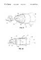
- FIG. 19shows a cannula 42 constructed in accordance with the present invention which is configured to be inserted into the femoral artery of the patient.
- the cannulais comprised of an expandable outer tubular elongate body 22 .
- the outer tubular elongate bodyis preferably constructed from irradiated polyethylene, PET or polyurethane film stock having a wall thickness of around 0.015 in.
- the cross section of the cannula 42 in its expanded statecan be seen with reference to FIG. 20 wherein the perfusion lumen 23 is shown fully expanded with an outer diameter of around 26 French and a wall thickness of about 0.015 in.
- the expandable member 24is configured to extend 75 to 80 cm into the aorta from the femoral artery and terminate in the ascending aorta.
- the distal end of the expandable tubular elongate body 22terminates in a plurality of arterial return apertures 30 as previously described.
- FIG. 19 bshows the distal end of the cannula 42 with the cannula fully expanded and the expandable member 24 inflated to occlude the vessel.
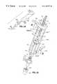
- Bloodenters the expandable tubular elongate body through a luer lock 120 or other connection means integrated into a co-axial “Y” fitting 122 provided at the proximal end of the cannula 42 .
- the bloodtravels to the distal end of the expandable outer tubular elongate body 22 through the perfusion lumen 23 and passes into the lumen of the aorta through the arterial return apertures 30 which may vary in number, spacing and placement from distal end.
- the cannulais also provided with a plurality of blood ports 126 distal to a non-expanding cannula portion 124 . Ports 126 are located inside the expandable portion 22 where the expandable portion proximally joins the distal end of portion 124 .
- the bloodflows out of portion 124 through ports 12 b and into lumen 23 inside tubular elongate body 22 .
- the cannula 42includes an inner tubular elongate body 44 having three internally disposed lumens, best seen in FIG. 20, including a saline inflation lumen 46 , a pressure lumen 48 , and a multi-function lumen 36 .
- the multi-function lumen 36can be used for cardioplegia, venting, insertion of a guidewire 27 , or other surgical tool or imaging device.
- the proximal end of the internally disposed inflation lumen 46is preferably attached to a standard balloon inflation fitting 128 for a syringe having saline solution therein.
- the multi-function lumen 36is preferably provided with a universal fitting 130 at the distal end which can accommodate either an external cardioplegia source (not shown), an inserted guidewire 27 or tool, or a vacuum venting source (not shown).
- the pressure lumen 48is configured at the proximal end with a standard pressure monitor luer port 132 with an opening and closing valve 134 .
- the inner tubular elongate body 44is preferably made from extruded pellothane polyurethane.
- an introduction sheathmay be used to advance the contracted cannula to the point of interest.
- the device of the present inventionmay be configured having a multi-function lumen 36 provided within the cannula for introduction of a guide wire 27 .
- the lumencan be configured to accept a number of different commercially available guide wires, including steerable guidewires, and guidewires specially shaped for passage through the aortic arch.
- the guidewiremay be removed for the remainder of the surgical procedure and the lumen 36 may be used to provide access to the aorta lumen for other devices and functions (e.g. insertion of a fiber-optic light camera, delivery of cardioplegia fluid or venting of the aorta lumen).
- radiographic markers 140are placed on the distal end 21 of the cannula to aid in the imaging of the device.
- Transoesophageal echocardiographymay also be used as an alternate means of imaging the device to insure correct placement within the aorta.
- Radiographic gradation markings 142may also be provided on the exterior of the outer tubular elongate body of the expandable cannula so that the operator may readily determine the extent to which the device has been inserted into the vessel.
- the expandable member 24when the device is properly inserted, the expandable member 24 is expanded to make secure contact with the interior of the aorta wall.
- the memberneed only be expanded to a point sufficient to substantially occlude the lumen of the aorta and prevent migration. Overexpansion of the balloon must be avoided as this may result in a rupturing or damaging of the aortic wall.
- a balloon diameter of around 3.5 cm and expansion pressure of about 250-350 mm Hghas been shown effective for this application.
- the expandable member 24may be an inflatable balloon made from such materials as polyethylene terephthalate (PET), polyvinyl chloride (PVC), ethylene vinyl acetate (EVA), silicon, latex, or some other such material.
- An inflation lumen 46is used to inflate the member and occlude the aorta.
- the expandable membermay also be comprised of a low density foam about which is disposed a substantially fluid impermeable member. The member is subjected to a vacuum through the inflation lumen 46 to maintain the member in a collapsed state. When the vacuum is released, the resilience of the foam causes the balloon to expand and occlude the aorta.
- the expandable memberis configured having an inner surface and an outer surface whereby on expansion of the member, the outer surface of the expandable member is expanded to contact an interior wall of the body passageway into which the expandable cannula is inserted. For aortic occlusion, the outer surface of the expandable member contacts the interior wall of the aorta so as to occlude the aorta.
- an internal lumen 36is configured to provide cardioplegia to the body vessel simultaneously with perfusion delivery.
- the lumen 36should be of sufficient diameter to provide cardioplegia flow at about 250 ml/min at around 200 mmHg pressure.
- a cross-sectional area in the range of 0.002 in 2 to 0.012 in 2has been found to be sufficient to meet these criterion.
- high pressure cardioplegia flowis undesirable as the cardioplegia solution may both “jet” against aortic root wall or valve tissue and may pressurize the coronary artery structure beyond normal aortic pressure, risking damage to the veins and aortic valve.
- the multi-function lumen 36may also be used to provide cardioplegia flow to the heart either intermittently or continuously.
- a pressure lumen 48is provided in the inner tubular elongate body 44 to monitor the pressure conditions upstream of the valve.
- the pressure lumenmay be integrally formed within the inner tubular elongate body 44 as seen in FIG. 20 or it may be contained in a separate structure maintained substantially parallel to the inner tubular elongate body 44 .
- the device of the present inventioncan also be used for imaging of the vessel interior during a surgical procedure.
- a multi-function lumen 36is provided which can provide access to a surgical instrument such as an imaging device.
- the imaging devicecan be used to provide optical visual information as to the condition of the vessel interior or the aortic valve.
- Other important imaging technologieswhich are suited for use with the device of the present invention include sonic, RF, X-ray, MRI, EPR, ESR, gamma ray, and microwave imaging devices.
- a cannulain another method of use, can be configured for insertion into the right or left subclavian of the patient. Because the cannula is only 13-15 French in its unexpanded state, insertion into the narrower subclavian arteries is possible. The procedure for preparation of the percutaneous incision or direct cut-down is similar with femoral access to the aorta. The cannula is also similarly prepared for insertion into the body so that air pockets are eliminated and the device is confined to the first diameter and inserted into a resilient introducer sheath having a hemostasis valve located at the proximal end of the introducer sheath 58 . Once the cannula is inserted into the subclavian artery as shown in FIG.
- the deviceis threaded into the aortic arch of the patient using the previously described methods. Once in place, the device is used in similar fashion as described above to provide arterial perfusion, cardioplegia, venting, and other functions within the aorta lumen.
- a second lumen 25 bmay be configured to provide flow to the patient's left side, for example, if the cannula is inserted into the left subclavian of the patient.
- a second cannulamay also be used for supplying arterial perfusion to the subclavian artery downstream of the access site.
- supplemental arterial supplymay be required because the lumen of the left subclavian may be significantly occluded once the cannula 42 is expanded so that perfusion is prevented from flowing through the left subclavian into the left side of the body.
- supplemental arterial flowcan be added via a single lumen arterial return cannula through the right subdlavian, as in FIG. 26 b , as the diameter of a single subclavian access site may not allow enough arterial blood flow to support the entire body.
Landscapes
- Health & Medical Sciences (AREA)
- Life Sciences & Earth Sciences (AREA)
- Public Health (AREA)
- General Health & Medical Sciences (AREA)
- Veterinary Medicine (AREA)
- Engineering & Computer Science (AREA)
- Biomedical Technology (AREA)
- Heart & Thoracic Surgery (AREA)
- Surgery (AREA)
- Animal Behavior & Ethology (AREA)
- Molecular Biology (AREA)
- Medical Informatics (AREA)
- Pathology (AREA)
- Nuclear Medicine, Radiotherapy & Molecular Imaging (AREA)
- Biophysics (AREA)
- Pulmonology (AREA)
- Anesthesiology (AREA)
- Hematology (AREA)
- External Artificial Organs (AREA)
Abstract
Description
Claims (6)
Priority Applications (1)
| Application Number | Priority Date | Filing Date | Title |
|---|---|---|---|
| US09/063,588US6190357B1 (en) | 1998-04-21 | 1998-04-21 | Expandable cannula for performing cardiopulmonary bypass and method for using same |
Applications Claiming Priority (1)
| Application Number | Priority Date | Filing Date | Title |
|---|---|---|---|
| US09/063,588US6190357B1 (en) | 1998-04-21 | 1998-04-21 | Expandable cannula for performing cardiopulmonary bypass and method for using same |
Publications (1)
| Publication Number | Publication Date |
|---|---|
| US6190357B1true US6190357B1 (en) | 2001-02-20 |
Family
ID=22050202
Family Applications (1)
| Application Number | Title | Priority Date | Filing Date |
|---|---|---|---|
| US09/063,588Expired - Fee RelatedUS6190357B1 (en) | 1998-04-21 | 1998-04-21 | Expandable cannula for performing cardiopulmonary bypass and method for using same |
Country Status (1)
| Country | Link |
|---|---|
| US (1) | US6190357B1 (en) |
Cited By (199)
| Publication number | Priority date | Publication date | Assignee | Title |
|---|---|---|---|---|
| US20020010418A1 (en)* | 2000-07-21 | 2002-01-24 | Syntheon, Llc | Methods and apparatus for sclerosing the wall of a varicose vein |
| US20020107531A1 (en)* | 2001-02-06 | 2002-08-08 | Schreck Stefan G. | Method and system for tissue repair using dual catheters |
| US6508777B1 (en)* | 1998-05-08 | 2003-01-21 | Cardeon Corporation | Circulatory support system and method of use for isolated segmental perfusion |
| US20030153946A1 (en)* | 2000-08-11 | 2003-08-14 | Edwards Lifesciences Ag | Device and method for treatment of atrioventricular regurgitation |
| US20030163081A1 (en)* | 2002-02-28 | 2003-08-28 | Constantz Brent R. | Localized fluid delivery devices having a porous applicator and methods for using the same |
| US20030187467A1 (en)* | 2002-03-26 | 2003-10-02 | Stefan Schreck | Sequential heart valve leaflet repair device and method of use |
| US20030204138A1 (en)* | 2002-04-25 | 2003-10-30 | Choi Steven B. | Dual balloon telescoping guiding catheter |
| US20030225421A1 (en)* | 2002-03-25 | 2003-12-04 | Nmt Medical, Inc. | Patent foramen ovale (PFO) closure clips |
| US20040019322A1 (en)* | 2002-07-23 | 2004-01-29 | Hoffmann Gerard Von | Intracranial aspiration catheter |
| US20040034320A1 (en)* | 2002-08-13 | 2004-02-19 | Burnett Daniel Rogers | Anti-reflux feeding tube |
| US20040044365A1 (en)* | 2002-09-03 | 2004-03-04 | Bachman Alan B. | Single catheter mitral valve repair device and method for use |
| US20040049213A1 (en)* | 2001-02-21 | 2004-03-11 | Terrence Buelna | Anastomosis occlusion device |
| WO2003008015A3 (en)* | 2001-07-19 | 2004-03-11 | Arteria Medical Science Inc | Catheter for removing emboli from saphenous vein grafts and native coronary arteries |
| US6706033B1 (en)* | 1999-08-02 | 2004-03-16 | Edwards Lifesciences Corporation | Modular access port for device delivery |
| US20040087968A1 (en)* | 2002-10-25 | 2004-05-06 | Nmt Medical, Inc. | Expandable sheath tubing |
| US20040093023A1 (en)* | 1999-10-21 | 2004-05-13 | Allen William J. | Minimally invasive mitral valve repair method and apparatus |
| US20040181238A1 (en)* | 2003-03-14 | 2004-09-16 | David Zarbatany | Mitral valve repair system and method for use |
| US20040193102A1 (en)* | 2003-03-28 | 2004-09-30 | Kurt Haggstrom | Catheter with occlusion resistant tip |
| US20050021047A1 (en)* | 2003-06-06 | 2005-01-27 | Voss Laveille Kao | Sizing and positioning adapter for medical instruments |
| US20050033222A1 (en)* | 2003-03-28 | 2005-02-10 | Kurt Haggstrom | Triple lumen catheter with occlusion resistant tip |
| US20050043585A1 (en)* | 2003-01-03 | 2005-02-24 | Arindam Datta | Reticulated elastomeric matrices, their manufacture and use in implantable devices |
| US20050043759A1 (en)* | 2003-07-14 | 2005-02-24 | Nmt Medical, Inc. | Tubular patent foramen ovale (PFO) closure device with catch system |
| US20050070842A1 (en)* | 2003-03-28 | 2005-03-31 | Mark Lotito | Catheter with occlusion resistant tip |
| US6875197B1 (en)* | 2000-11-14 | 2005-04-05 | Advanced Cardiovascular Systems, Inc. | Dimensionally stable and growth controlled inflatable member for a catheter |
| US20050080430A1 (en)* | 2003-08-19 | 2005-04-14 | Nmt Medical, Inc. | Expandable sheath tubing |
| US20050107817A1 (en)* | 2001-12-14 | 2005-05-19 | White Jennifer K. | Dynamic cannula |
| US20050107738A1 (en)* | 2000-07-21 | 2005-05-19 | Slater Charles R. | Occludable intravascular catheter for drug delivery and method of using the same |
| US20050131432A1 (en)* | 2003-12-12 | 2005-06-16 | Novare Surgical Systems, Inc. | Device and method for performing multiple anastomoses |
| US20050273119A1 (en)* | 2003-12-09 | 2005-12-08 | Nmt Medical, Inc. | Double spiral patent foramen ovale closure clamp |
| US20050273124A1 (en)* | 2004-05-06 | 2005-12-08 | Nmt Medical, Inc. | Delivery systems and methods for PFO closure device with two anchors |
| US20060041304A1 (en)* | 1999-12-22 | 2006-02-23 | Yue-Teh Jang | Endoluminal occlusion-irrigation catheter with aspiration capabilities and methods of use |
| EP1427460A4 (en)* | 2001-07-26 | 2006-05-03 | Gore Enterprise Holdings Inc | CATHETER WITH RADIAL EXPANDABLE MAIN BODY |
| US20060116714A1 (en)* | 2004-11-26 | 2006-06-01 | Ivan Sepetka | Coupling and release devices and methods for their assembly and use |
| US20060116629A1 (en)* | 2004-11-04 | 2006-06-01 | Tal Michael G | Catheter insertion apparatus |
| US20060122647A1 (en)* | 2004-09-24 | 2006-06-08 | Callaghan David J | Occluder device double securement system for delivery/recovery of such occluder device |
| US20060124134A1 (en)* | 2004-12-15 | 2006-06-15 | Wood Scott D | Tracheostomy system |
| US20060135916A1 (en)* | 2004-12-16 | 2006-06-22 | Smiths Medical Asd, Inc. | Catheter with direction orientation |
| US20060137345A1 (en)* | 2004-12-23 | 2006-06-29 | Doosan Infracore Co., Ltd. | Compressed air supplying apparatus for use in heavy construction equipments |
| US20060149218A1 (en)* | 2003-02-05 | 2006-07-06 | Slater Charles R | Methods and apparatus for treating the interior of a blood vessel |
| US20060178622A1 (en)* | 2002-10-29 | 2006-08-10 | Constantz Brent R | Devices and methods for treating aortic valve stenosis |
| US20060200002A1 (en)* | 2003-01-15 | 2006-09-07 | Guenst Gary W | Methods and tools for accessing an anatomic space |
| US20070010851A1 (en)* | 2003-07-14 | 2007-01-11 | Chanduszko Andrzej J | Tubular patent foramen ovale (PFO) closure device with catch system |
| US20070066943A1 (en)* | 2005-09-21 | 2007-03-22 | Abiomed, Inc. | Cannula systems and methods of use |
| US20070093689A1 (en)* | 1995-09-04 | 2007-04-26 | Active Implants Corporation | Method and apparatus for computerized surgery |
| US20070118176A1 (en)* | 2005-10-24 | 2007-05-24 | Opolski Steven W | Radiopaque bioabsorbable occluder |
| WO2007057127A1 (en)* | 2005-11-15 | 2007-05-24 | Andreas Horn | Expandable device for insertion into organ and/or body orifices |
| US20070135791A1 (en)* | 2004-08-19 | 2007-06-14 | Slater Charles R | Method for Infusing the Interior of a Blood Vessel |
| US20070197997A1 (en)* | 2005-10-24 | 2007-08-23 | Wilson-Cook Medical Inc. | Method of removing biliary stones with coaxial catheter device |
| US20070232941A1 (en)* | 2005-10-27 | 2007-10-04 | Stan Rabinovich | System, apparatus, and method for imaging and treating tissue |
| US20070265642A1 (en)* | 2002-01-14 | 2007-11-15 | Nmt Medical, Inc. | Patent foramen ovale (PFO) closure method and device |
| US20070299462A1 (en)* | 2006-06-23 | 2007-12-27 | Becker Bruce B | Nasolacrimal system irrigation and dilatation tool |
| US20080004571A1 (en)* | 2006-06-28 | 2008-01-03 | Abbott Laboratories | Expandable introducer sheath |
| US20080004569A1 (en)* | 2006-06-28 | 2008-01-03 | Abbott Laboratories | Expandable Introducer Sheath to Preserve Guidewire Access |
| US20080065156A1 (en)* | 2006-09-08 | 2008-03-13 | Hauser David L | Expandable clip for tissue repair |
| US20080082083A1 (en)* | 2006-09-28 | 2008-04-03 | Forde Sean T | Perforated expandable implant recovery sheath |
| US20080097471A1 (en)* | 2006-10-18 | 2008-04-24 | Adams Ronald D | Systems for performing gynecological procedures with simultaneous tissue cutting and removal |
| WO2008058157A2 (en) | 2006-11-07 | 2008-05-15 | Interlace Medical, Inc. | Systems for mechanically expanding, examining and treating a uterus |
| US20080135053A1 (en)* | 2006-11-07 | 2008-06-12 | William Harwick Gruber | Methods, systems and devices for performing gynecological procedures |
| US20080188873A1 (en)* | 2005-01-21 | 2008-08-07 | Giovanni Speziali | Thorascopic Heart Valve Repair Method and Apparatus |
| US20080200873A1 (en)* | 2007-02-16 | 2008-08-21 | Alejandro Espinosa | Methods and Apparatus for Infusing the Interior of a Blood Vessel |
| US20080243170A1 (en)* | 2007-03-30 | 2008-10-02 | Boston Scientific Scimed, Inc. | Embolic capturing devices and methods |
| US20080243066A1 (en)* | 2007-03-30 | 2008-10-02 | Boston Scientific Scimed, Inc. | Perfusion and embolic protection |
| US20080243072A1 (en)* | 2007-03-30 | 2008-10-02 | Boston Scientific Scimed, Inc. | Perfusion Device |
| US20080249553A1 (en)* | 2007-04-06 | 2008-10-09 | William Harwick Gruber | Method, system and device for tissue removal |
| US20080245371A1 (en)* | 2007-04-06 | 2008-10-09 | William Harwick Gruber | Systems, methods and devices for performing gynecological procedures |
| US20080281356A1 (en)* | 2007-05-08 | 2008-11-13 | Mark Chau | Suture-fastening clip |
| US20080281350A1 (en)* | 2006-12-13 | 2008-11-13 | Biomerix Corporation | Aneurysm Occlusion Devices |
| US20090105729A1 (en)* | 2007-10-18 | 2009-04-23 | John Zentgraf | Minimally invasive repair of a valve leaflet in a beating heart |
| US20090209907A1 (en)* | 2008-02-15 | 2009-08-20 | Paul John Grata | Single-Use Indicator For A Surgical Instrument And A Surgical Instrument Incorporating Same |
| US20090270897A1 (en)* | 2007-04-06 | 2009-10-29 | Interlace Medical, Inc. | Methods of high rate, low profile tissue removal |
| US20090270896A1 (en)* | 2007-04-06 | 2009-10-29 | Interlace Medical, Inc. | Tissue cutter with differential hardness |
| US20090301643A1 (en)* | 2008-06-02 | 2009-12-10 | Loma Vista Medical, Inc. | Inflatable medical devices |
| US20100099949A1 (en)* | 2007-01-30 | 2010-04-22 | Alexander Quillin Tilson | Biological navigation device |
| US20100114017A1 (en)* | 2002-07-23 | 2010-05-06 | Reverse Medical Corporation | Systems and methods for removing obstructive matter from body lumens and treating vascular defects |
| US20100130937A1 (en)* | 2005-06-30 | 2010-05-27 | Abbott Vascular Inc. | Introducer sheath and methods of making |
| US20100130939A1 (en)* | 2005-06-30 | 2010-05-27 | Abbott Vascular Inc. | Introducer sheath and methods of making |
| US20100130936A1 (en)* | 2005-06-30 | 2010-05-27 | Abbott Vascular Inc. | Introducer sheath and methods of making |
| US7763077B2 (en) | 2003-12-24 | 2010-07-27 | Biomerix Corporation | Repair of spinal annular defects and annulo-nucleoplasty regeneration |
| US20100198160A1 (en)* | 2006-06-28 | 2010-08-05 | Abbott Vascular Inc. | Expandable Introducer Sheaths and Methods for Manufacture and Use |
| US20100198159A1 (en)* | 2006-06-28 | 2010-08-05 | Abbott Vascular Inc. | Expandable introducer sheath to preserve guidewire access |
| US7803395B2 (en) | 2003-05-15 | 2010-09-28 | Biomerix Corporation | Reticulated elastomeric matrices, their manufacture and use in implantable devices |
| US7842053B2 (en) | 2004-05-06 | 2010-11-30 | Nmt Medical, Inc. | Double coil occluder |
| US20100331780A1 (en)* | 2009-06-26 | 2010-12-30 | Tyco Healthcare Group Lp | Catheterization System |
| US7914436B1 (en)* | 2006-06-12 | 2011-03-29 | Abiomed, Inc. | Method and apparatus for pumping blood |
| US20110184530A1 (en)* | 2004-05-17 | 2011-07-28 | Biomerix Corporation | High performance reticulated elastomeric matrix preparation, properties, reinforcement, and use in surgical devices, tissue augmentation and/or tissue repair |
| US20120083877A1 (en)* | 2008-10-10 | 2012-04-05 | Duy Nguyen | Expandable sheath for introducing an endovascular delivery device into a body |
| US20120296152A1 (en)* | 2009-05-20 | 2012-11-22 | Thoratec Corporation | Multi-lumen cannula |
| US8551135B2 (en) | 2006-03-31 | 2013-10-08 | W.L. Gore & Associates, Inc. | Screw catch mechanism for PFO occluder and method of use |
| US20130345796A1 (en)* | 2012-06-26 | 2013-12-26 | St. Jude Medical, Cardiology Division, Inc. | Apparatus and method for aortic protection and tavi planar alignment |
| US8747343B2 (en) | 2011-09-30 | 2014-06-10 | Covidien Lp | Hemodialysis catheter with improved side opening design |
| US8784448B2 (en) | 2002-06-05 | 2014-07-22 | W.L. Gore & Associates, Inc. | Patent foramen ovale (PFO) closure device with radial and circumferential support |
| US20140222139A1 (en)* | 2008-10-10 | 2014-08-07 | Edwards Lifesciences Corporation | Expandable introducer sheath |
| US8852253B2 (en) | 2012-01-27 | 2014-10-07 | Kyphon Sarl | Anchoring cannula |
| US8948848B2 (en) | 2011-01-07 | 2015-02-03 | Innovative Cardiovascular Solutions, Llc | Angiography catheter |
| US9017373B2 (en) | 2002-12-09 | 2015-04-28 | W.L. Gore & Associates, Inc. | Septal closure devices |
| US9044221B2 (en) | 2010-12-29 | 2015-06-02 | Neochord, Inc. | Exchangeable system for minimally invasive beating heart repair of heart valve leaflets |
| US9072867B2 (en) | 2011-09-30 | 2015-07-07 | Covidien Lp | Catheter with external flow channel |
| US9138562B2 (en) | 2007-04-18 | 2015-09-22 | W.L. Gore & Associates, Inc. | Flexible catheter system |
| US9155862B2 (en) | 2012-09-28 | 2015-10-13 | Covidien Lp | Symmetrical tip acute catheter |
| US9168359B2 (en) | 2005-06-30 | 2015-10-27 | Abbott Laboratories | Modular introducer and exchange sheath |
| US9168352B2 (en) | 2011-12-19 | 2015-10-27 | Cardiacassist, Inc. | Dual lumen cannula |
| US9192746B2 (en) | 2010-06-07 | 2015-11-24 | Cook Medical Technologies Llc | Reperfusion catheter system |
| US9248221B2 (en) | 2014-04-08 | 2016-02-02 | Incuvate, Llc | Aspiration monitoring system and method |
| US9352118B2 (en) | 2005-06-30 | 2016-05-31 | Abbott Laboratories | Modular introducer and exchange sheath |
| US9370422B2 (en) | 2011-07-28 | 2016-06-21 | St. Jude Medical, Inc. | Expandable radiopaque marker for transcatheter aortic valve implantation |
| US9433427B2 (en) | 2014-04-08 | 2016-09-06 | Incuvate, Llc | Systems and methods for management of thrombosis |
| US9439795B2 (en) | 2010-09-17 | 2016-09-13 | St. Jude Medical, Cardiology Division, Inc. | Retainers for transcatheter heart valve delivery systems |
| US20160296730A1 (en)* | 2015-04-10 | 2016-10-13 | Edwards Lifesciences Corporation | Expandable sheath |
| US9474517B2 (en) | 2008-03-07 | 2016-10-25 | W. L. Gore & Associates, Inc. | Heart occlusion devices |
| US20160331207A1 (en)* | 2015-05-13 | 2016-11-17 | Tamer Ibrahim | Access visualization systems |
| US9498249B2 (en) | 2012-11-21 | 2016-11-22 | P Tech, Llc | Expandable access systems and methods |
| US20170049991A1 (en)* | 2011-12-07 | 2017-02-23 | Traumatek Solutions, B.V. | Devices and methods for endovascular access and therapy |
| US9592119B2 (en) | 2010-07-13 | 2017-03-14 | C.R. Bard, Inc. | Inflatable medical devices |
| US9675740B2 (en) | 2012-05-14 | 2017-06-13 | Tc1 Llc | Impeller for catheter pump |
| US9675739B2 (en) | 2015-01-22 | 2017-06-13 | Tc1 Llc | Motor assembly with heat exchanger for catheter pump |
| US9675738B2 (en) | 2015-01-22 | 2017-06-13 | Tc1 Llc | Attachment mechanisms for motor of catheter pump |
| US9717833B2 (en) | 2004-09-17 | 2017-08-01 | The Penn State Research Foundation | Heart assist device with expandable impeller pump |
| US9770232B2 (en) | 2011-08-12 | 2017-09-26 | W. L. Gore & Associates, Inc. | Heart occlusion devices |
| US9770543B2 (en) | 2015-01-22 | 2017-09-26 | Tc1 Llc | Reduced rotational mass motor assembly for catheter pump |
| US9808230B2 (en) | 2014-06-06 | 2017-11-07 | W. L. Gore & Associates, Inc. | Sealing device and delivery system |
| US9827356B2 (en) | 2014-04-15 | 2017-11-28 | Tc1 Llc | Catheter pump with access ports |
| US9861346B2 (en) | 2003-07-14 | 2018-01-09 | W. L. Gore & Associates, Inc. | Patent foramen ovale (PFO) closure device with linearly elongating petals |
| US9872947B2 (en) | 2012-05-14 | 2018-01-23 | Tc1 Llc | Sheath system for catheter pump |
| US9883877B2 (en) | 2014-05-19 | 2018-02-06 | Walk Vascular, Llc | Systems and methods for removal of blood and thrombotic material |
| US9889275B2 (en) | 2006-06-28 | 2018-02-13 | Abbott Laboratories | Expandable introducer sheath to preserve guidewire access |
| US9918837B2 (en) | 2012-06-29 | 2018-03-20 | St. Jude Medical, Cardiology Division, Inc. | System to assist in the release of a collapsible stent from a delivery device |
| US9949728B2 (en) | 2007-04-05 | 2018-04-24 | W.L. Gore & Associates, Inc. | Septal closure device with centering mechanism |
| US9962475B2 (en) | 2011-01-06 | 2018-05-08 | Tc1 Llc | Percutaneous heart pump |
| US10010344B2 (en)* | 2015-07-13 | 2018-07-03 | Dennis L Steffen | Self-dilating catheter introducer with obturator and method of use |
| US10058676B2 (en) | 2009-09-30 | 2018-08-28 | Covidien Lp | Medical catheter having a design providing low recirculation and reversibility |
| US10071192B2 (en) | 2013-03-15 | 2018-09-11 | Tc1 Llp | Catheter pump assembly including a stator |
| US10086121B2 (en) | 2012-07-03 | 2018-10-02 | Tc1 Llc | Catheter pump |
| US10105475B2 (en) | 2014-04-15 | 2018-10-23 | Tc1 Llc | Catheter pump introducer systems and methods |
| US10118020B2 (en) | 2011-12-07 | 2018-11-06 | Traumatek Solutions B.V. | Devices and methods for endovascular access and therapy |
| US10117980B2 (en) | 2012-05-14 | 2018-11-06 | Tc1 Llc | Distal bearing support |
| US20180318078A1 (en)* | 2017-05-05 | 2018-11-08 | St. Jude Medical, Cardiology Division, Inc. | Introducer sheath having expandable portions |
| US10130470B2 (en) | 2010-08-17 | 2018-11-20 | St. Jude Medical, Llc | Sleeve for facilitating movement of a transfemoral catheter |
| US10188436B2 (en) | 2010-11-09 | 2019-01-29 | Loma Vista Medical, Inc. | Inflatable medical devices |
| US10215187B2 (en) | 2004-09-17 | 2019-02-26 | Tc1 Llc | Expandable impeller pump |
| US10226263B2 (en) | 2015-12-23 | 2019-03-12 | Incuvate, Llc | Aspiration monitoring system and method |
| US10327896B2 (en) | 2015-04-10 | 2019-06-25 | Edwards Lifesciences Corporation | Expandable sheath with elastomeric cross sectional portions |
| US10363349B2 (en) | 2014-04-15 | 2019-07-30 | Tc1 Llp | Heart pump providing adjustable outflow |
| US10398550B2 (en) | 2013-09-12 | 2019-09-03 | St. Jude Medical, Cardiology Division, Inc. | Atraumatic interface in an implant delivery device |
| US10449279B2 (en) | 2014-08-18 | 2019-10-22 | Tc1 Llc | Guide features for percutaneous catheter pump |
| US10525178B2 (en) | 2013-03-15 | 2020-01-07 | Tc1 Llc | Catheter pump assembly including a stator |
| US10561440B2 (en) | 2015-09-03 | 2020-02-18 | Vesatek, Llc | Systems and methods for manipulating medical devices |
| US10576193B2 (en) | 2012-07-03 | 2020-03-03 | Tc1 Llc | Motor assembly for catheter pump |
| US10583232B2 (en) | 2014-04-15 | 2020-03-10 | Tc1 Llc | Catheter pump with off-set motor position |
| US10588620B2 (en) | 2018-03-23 | 2020-03-17 | Neochord, Inc. | Device for suture attachment for minimally invasive heart valve repair |
| US10603195B1 (en) | 2015-05-20 | 2020-03-31 | Paul Sherburne | Radial expansion and contraction features of medical devices |
| US10632241B2 (en) | 2013-03-13 | 2020-04-28 | Tc1 Llc | Fluid handling system |
| US10667907B2 (en) | 2016-05-13 | 2020-06-02 | St. Jude Medical, Cardiology Division, Inc. | Systems and methods for device implantation |
| US10695178B2 (en) | 2011-06-01 | 2020-06-30 | Neochord, Inc. | Minimally invasive repair of heart valve leaflets |
| US10702292B2 (en) | 2015-08-28 | 2020-07-07 | Incuvate, Llc | Aspiration monitoring system and method |
| US10765517B2 (en) | 2015-10-01 | 2020-09-08 | Neochord, Inc. | Ringless web for repair of heart valves |
| US10792025B2 (en) | 2009-06-22 | 2020-10-06 | W. L. Gore & Associates, Inc. | Sealing device and delivery system |
| US10799685B2 (en) | 2017-03-09 | 2020-10-13 | Edwards Lifesciences Corporation | Expandable sheath with longitudinally extending reinforcing members |
| US10806437B2 (en) | 2009-06-22 | 2020-10-20 | W. L. Gore & Associates, Inc. | Sealing device and delivery system |
| US10828019B2 (en) | 2013-01-18 | 2020-11-10 | W.L. Gore & Associates, Inc. | Sealing device and delivery system |
| US10850064B2 (en) | 2015-09-03 | 2020-12-01 | St. Jude Medical, Cardiology Division, Inc. | Introducer sheath having expandable portions |
| US10864308B2 (en) | 2014-04-15 | 2020-12-15 | Tc1 Llc | Sensors for catheter pumps |
| US10912919B2 (en) | 2017-01-23 | 2021-02-09 | Edwards Lifesciences Corporation | Expandable sheath |
| US10918829B2 (en) | 2015-01-22 | 2021-02-16 | Boston Scientific Scimed, Inc. | Fully compliant large bore expandable sheath |
| US10966709B2 (en) | 2018-09-07 | 2021-04-06 | Neochord, Inc. | Device for suture attachment for minimally invasive heart valve repair |
| US10987488B2 (en) | 2015-06-23 | 2021-04-27 | Traumatek Solutions, B.V. | Vessel cannulation device and method of use |
| US11071844B2 (en) | 2018-03-07 | 2021-07-27 | Innovative Cardiovascular Solutions, Llc | Embolic protection device |
| US11077294B2 (en) | 2013-03-13 | 2021-08-03 | Tc1 Llc | Sheath assembly for catheter pump |
| US11122971B2 (en) | 2016-08-18 | 2021-09-21 | Neptune Medical Inc. | Device and method for enhanced visualization of the small intestine |
| US11129959B2 (en) | 2018-02-15 | 2021-09-28 | Boston Scientific Scimed, Inc. | Introducer with expandable capabilities |
| US11135398B2 (en) | 2018-07-19 | 2021-10-05 | Neptune Medical Inc. | Dynamically rigidizing composite medical structures |
| US11160970B2 (en) | 2016-07-21 | 2021-11-02 | Tc1 Llc | Fluid seals for catheter pump motor assembly |
| US11173030B2 (en) | 2018-05-09 | 2021-11-16 | Neochord, Inc. | Suture length adjustment for minimally invasive heart valve repair |
| US11219351B2 (en) | 2015-09-03 | 2022-01-11 | Neptune Medical Inc. | Device for endoscopic advancement through the small intestine |
| US11229786B2 (en) | 2012-05-14 | 2022-01-25 | Tc1 Llc | Impeller for catheter pump |
| US11253360B2 (en) | 2018-05-09 | 2022-02-22 | Neochord, Inc. | Low profile tissue anchor for minimally invasive heart valve repair |
| US11273062B2 (en) | 2018-04-09 | 2022-03-15 | Edwards Lifesciences Corporation | Expandable sheath |
| US11376126B2 (en) | 2019-04-16 | 2022-07-05 | Neochord, Inc. | Transverse helical cardiac anchor for minimally invasive heart valve repair |
| US11491322B2 (en) | 2016-07-21 | 2022-11-08 | Tc1 Llc | Gas-filled chamber for catheter pump motor assembly |
| US11497521B2 (en) | 2008-10-13 | 2022-11-15 | Walk Vascular, Llc | Assisted aspiration catheter system |
| US11510689B2 (en) | 2016-04-06 | 2022-11-29 | Walk Vascular, Llc | Systems and methods for thrombolysis and delivery of an agent |
| US11540847B2 (en) | 2015-10-09 | 2023-01-03 | Incuvate, Llc | Systems and methods for management of thrombosis |
| US11589989B2 (en) | 2017-03-31 | 2023-02-28 | Neochord, Inc. | Minimally invasive heart valve repair in a beating heart |
| US11653945B2 (en) | 2007-02-05 | 2023-05-23 | Walk Vascular, Llc | Thrombectomy apparatus and method |
| US11678905B2 (en) | 2018-07-19 | 2023-06-20 | Walk Vascular, Llc | Systems and methods for removal of blood and thrombotic material |
| US11744443B2 (en) | 2020-03-30 | 2023-09-05 | Neptune Medical Inc. | Layered walls for rigidizing devices |
| US11786695B2 (en) | 2018-07-25 | 2023-10-17 | Edwards Lifesciences Corporation | Methods of making an expandable sheath |
| US11793392B2 (en) | 2019-04-17 | 2023-10-24 | Neptune Medical Inc. | External working channels |
| US11850414B2 (en) | 2013-03-13 | 2023-12-26 | Tc1 Llc | Fluid handling system |
| US11903602B2 (en) | 2009-04-29 | 2024-02-20 | Hologic, Inc. | Uterine fibroid tissue removal device |
| US11937778B2 (en) | 2022-04-27 | 2024-03-26 | Neptune Medical Inc. | Apparatuses and methods for determining if an endoscope is contaminated |
| US12059128B2 (en) | 2018-05-31 | 2024-08-13 | Neptune Medical Inc. | Device and method for enhanced visualization of the small intestine |
| US12121677B2 (en) | 2021-01-29 | 2024-10-22 | Neptune Medical Inc. | Devices and methods to prevent inadvertent motion of dynamically rigidizing apparatuses |
| US12171445B2 (en) | 2021-02-15 | 2024-12-24 | Walk Vascular, Llc | Systems and methods for removal of blood and thrombotic material |
| US12194256B2 (en) | 2015-04-10 | 2025-01-14 | Edwards Lifesciences Corporation | Expandable sheath |
| US12208007B2 (en) | 2020-01-16 | 2025-01-28 | Neochord, Inc. | Helical cardiac anchors for minimally invasive heart valve repair |
| US12274458B2 (en) | 2021-02-15 | 2025-04-15 | Walk Vascular, Llc | Systems and methods for removal of blood and thrombotic material |
| US12295550B2 (en) | 2017-07-20 | 2025-05-13 | Neptune Medical Inc. | Dynamically rigidizing overtube |
| US12329473B2 (en) | 2019-04-17 | 2025-06-17 | Neptune Medical Inc. | Dynamically rigidizing composite medical structures |
| US12330292B2 (en) | 2023-09-28 | 2025-06-17 | Neptune Medical Inc. | Telescoping robot |
Citations (23)
| Publication number | Priority date | Publication date | Assignee | Title |
|---|---|---|---|---|
| US4141364A (en) | 1977-03-18 | 1979-02-27 | Jorge Schultze | Expandable endotracheal or urethral tube |
| US4479497A (en) | 1982-11-12 | 1984-10-30 | Thomas J. Fogarty | Double lumen dilatation catheter |
| US4589868A (en) | 1984-03-12 | 1986-05-20 | Dretler Stephen P | Expandable dilator-catheter |
| US4601713A (en) | 1985-06-11 | 1986-07-22 | Genus Catheter Technologies, Inc. | Variable diameter catheter |
| US4738666A (en) | 1985-06-11 | 1988-04-19 | Genus Catheter Technologies, Inc. | Variable diameter catheter |
| US4846791A (en) | 1988-09-02 | 1989-07-11 | Advanced Medical Technology & Development Corp. | Multi-lumen catheter |
| US4896669A (en) | 1988-08-31 | 1990-01-30 | Meadox Medicals, Inc. | Dilatation catheter |
| EP0385920A2 (en) | 1989-03-03 | 1990-09-05 | Thomas J. Fogarty | Variable diameter sheath apparatus for use in body passages |
| US4955895A (en) | 1986-12-23 | 1990-09-11 | Terumo Kabushiki Kaisha | Vasodilating catheter |
| US5176659A (en) | 1991-02-28 | 1993-01-05 | Mario Mancini | Expandable intravenous catheter and method of using |
| US5183464A (en) | 1991-05-17 | 1993-02-02 | Interventional Thermodynamics, Inc. | Radially expandable dilator |
| US5234425A (en) | 1989-03-03 | 1993-08-10 | Thomas J. Fogarty | Variable diameter sheath method and apparatus for use in body passages |
| US5425708A (en) | 1991-12-13 | 1995-06-20 | Nissho Corporation | Catheter with an aorta-occluding balloon |
| US5452733A (en) | 1993-02-22 | 1995-09-26 | Stanford Surgical Technologies, Inc. | Methods for performing thoracoscopic coronary artery bypass |
| US5573508A (en) | 1994-11-22 | 1996-11-12 | Advanced Cardiovascular Systems, Inc. | Catheter with an expandable perfusion lumen |
| US5573517A (en) | 1993-02-04 | 1996-11-12 | Peter M. Bonutti | Expandable cannulas |
| US5573509A (en) | 1994-11-22 | 1996-11-12 | Advanced Cardiovascular Systems, Inc. | Catheter with an expandable perfusion slit |
| US5584803A (en) | 1991-07-16 | 1996-12-17 | Heartport, Inc. | System for cardiac procedures |
| US5674240A (en) | 1993-02-04 | 1997-10-07 | Peter M. Bonutti | Expandable cannula |
| US5707354A (en) | 1995-04-17 | 1998-01-13 | Cardiovascular Imaging Systems, Inc. | Compliant catheter lumen and methods |
| US5755687A (en) | 1997-04-01 | 1998-05-26 | Heartport, Inc. | Methods and devices for occluding a patient's ascending aorta |
| US5810721A (en) | 1996-03-04 | 1998-09-22 | Heartport, Inc. | Soft tissue retractor and method for providing surgical access |
| US5827243A (en)* | 1996-11-29 | 1998-10-27 | Palestrant; Aubrey M. | Collapsible aspiration catheter |
- 1998
- 1998-04-21USUS09/063,588patent/US6190357B1/ennot_activeExpired - Fee Related
Patent Citations (24)
| Publication number | Priority date | Publication date | Assignee | Title |
|---|---|---|---|---|
| US4141364A (en) | 1977-03-18 | 1979-02-27 | Jorge Schultze | Expandable endotracheal or urethral tube |
| US4479497A (en) | 1982-11-12 | 1984-10-30 | Thomas J. Fogarty | Double lumen dilatation catheter |
| US4589868A (en) | 1984-03-12 | 1986-05-20 | Dretler Stephen P | Expandable dilator-catheter |
| US4601713A (en) | 1985-06-11 | 1986-07-22 | Genus Catheter Technologies, Inc. | Variable diameter catheter |
| US4738666A (en) | 1985-06-11 | 1988-04-19 | Genus Catheter Technologies, Inc. | Variable diameter catheter |
| US4955895A (en) | 1986-12-23 | 1990-09-11 | Terumo Kabushiki Kaisha | Vasodilating catheter |
| US4896669A (en) | 1988-08-31 | 1990-01-30 | Meadox Medicals, Inc. | Dilatation catheter |
| US4846791A (en) | 1988-09-02 | 1989-07-11 | Advanced Medical Technology & Development Corp. | Multi-lumen catheter |
| EP0385920A2 (en) | 1989-03-03 | 1990-09-05 | Thomas J. Fogarty | Variable diameter sheath apparatus for use in body passages |
| US5234425A (en) | 1989-03-03 | 1993-08-10 | Thomas J. Fogarty | Variable diameter sheath method and apparatus for use in body passages |
| US5176659A (en) | 1991-02-28 | 1993-01-05 | Mario Mancini | Expandable intravenous catheter and method of using |
| US5183464A (en) | 1991-05-17 | 1993-02-02 | Interventional Thermodynamics, Inc. | Radially expandable dilator |
| US5584803A (en) | 1991-07-16 | 1996-12-17 | Heartport, Inc. | System for cardiac procedures |
| US5425708A (en) | 1991-12-13 | 1995-06-20 | Nissho Corporation | Catheter with an aorta-occluding balloon |
| US5573517A (en) | 1993-02-04 | 1996-11-12 | Peter M. Bonutti | Expandable cannulas |
| US5601590A (en) | 1993-02-04 | 1997-02-11 | General Surgical Innovations, Inc. | Expandable cannulas |
| US5674240A (en) | 1993-02-04 | 1997-10-07 | Peter M. Bonutti | Expandable cannula |
| US5452733A (en) | 1993-02-22 | 1995-09-26 | Stanford Surgical Technologies, Inc. | Methods for performing thoracoscopic coronary artery bypass |
| US5573508A (en) | 1994-11-22 | 1996-11-12 | Advanced Cardiovascular Systems, Inc. | Catheter with an expandable perfusion lumen |
| US5573509A (en) | 1994-11-22 | 1996-11-12 | Advanced Cardiovascular Systems, Inc. | Catheter with an expandable perfusion slit |
| US5707354A (en) | 1995-04-17 | 1998-01-13 | Cardiovascular Imaging Systems, Inc. | Compliant catheter lumen and methods |
| US5810721A (en) | 1996-03-04 | 1998-09-22 | Heartport, Inc. | Soft tissue retractor and method for providing surgical access |
| US5827243A (en)* | 1996-11-29 | 1998-10-27 | Palestrant; Aubrey M. | Collapsible aspiration catheter |
| US5755687A (en) | 1997-04-01 | 1998-05-26 | Heartport, Inc. | Methods and devices for occluding a patient's ascending aorta |
Cited By (484)
| Publication number | Priority date | Publication date | Assignee | Title |
|---|---|---|---|---|
| US20080071374A1 (en)* | 1995-09-04 | 2008-03-20 | Active Implants Corporation | Method and apparatus for computerized surgery |
| US20070093689A1 (en)* | 1995-09-04 | 2007-04-26 | Active Implants Corporation | Method and apparatus for computerized surgery |
| US6508777B1 (en)* | 1998-05-08 | 2003-01-21 | Cardeon Corporation | Circulatory support system and method of use for isolated segmental perfusion |
| US20080147188A1 (en)* | 1999-03-07 | 2008-06-19 | Active Implants Corporation | Method and apparatus for computerized surgery |
| US20080108994A1 (en)* | 1999-03-07 | 2008-05-08 | Active Implants Corporation | Method and apparatus for computerized surgery |
| US9017313B2 (en) | 1999-03-07 | 2015-04-28 | Nuvasive, Inc. | Method and apparatus for computerized surgery |
| US20080058838A1 (en)* | 1999-03-07 | 2008-03-06 | Active Implants Corporation | Method and apparatus for computerized surgery |
| US20080065067A1 (en)* | 1999-03-07 | 2008-03-13 | Active Implants Corporation | Method and apparatus for computerized surgery |
| US9668875B2 (en) | 1999-03-07 | 2017-06-06 | Nuvasive, Inc. | Method and apparatus for computerized surgery |
| US9827109B2 (en) | 1999-03-07 | 2017-11-28 | Nuvasive, Inc. | Methods and apparatus for performing spine surgery |
| US20080114376A1 (en)* | 1999-03-07 | 2008-05-15 | Active Implants Corporation | Method and apparatus for computerized surgery |
| US6706033B1 (en)* | 1999-08-02 | 2004-03-16 | Edwards Lifesciences Corporation | Modular access port for device delivery |
| US7758595B2 (en) | 1999-10-21 | 2010-07-20 | Edwards Lifesciences Corporation | Minimally invasive mitral valve repair method and apparatus |
| US7112207B2 (en) | 1999-10-21 | 2006-09-26 | Edwards Lifesciences Corporation | Minimally invasive mitral valve repair method and apparatus |
| US20060064116A1 (en)* | 1999-10-21 | 2006-03-23 | Allen William J | Minimally invasive mitral valve repair method and apparatus |
| US20040093023A1 (en)* | 1999-10-21 | 2004-05-13 | Allen William J. | Minimally invasive mitral valve repair method and apparatus |
| US20060064115A1 (en)* | 1999-10-21 | 2006-03-23 | Allen William J | Minimally invasive mitral valve repair method and apparatus |
| US7744609B2 (en) | 1999-10-21 | 2010-06-29 | Edwards Lifesciences Corporation | Minimally invasive mitral valve repair method and apparatus |
| US8361086B2 (en) | 1999-10-21 | 2013-01-29 | Edwards Lifesciences Corporation | Minimally invasive mitral valve repair method and apparatus |
| US20100234813A1 (en)* | 1999-10-21 | 2010-09-16 | Allen William J | Minimally invasive mitral valve repair method and apparatus |
| US20100222736A1 (en)* | 1999-12-22 | 2010-09-02 | Boston Scientific Scimed, Inc. | Endoluminal occlusion-irrigation catheter with aspiration capabilities and methods of use |
| US8152782B2 (en) | 1999-12-22 | 2012-04-10 | Boston Scientific Scimed, Inc. | Endoluminal occlusion-irrigation catheter with aspiration capabilities and methods of use |
| US20060041304A1 (en)* | 1999-12-22 | 2006-02-23 | Yue-Teh Jang | Endoluminal occlusion-irrigation catheter with aspiration capabilities and methods of use |
| US7731683B2 (en) | 1999-12-22 | 2010-06-08 | Boston Scientific Scimed, Inc. | Endoluminal occlusion-irrigation catheter with aspiration capabilities and methods of use |
| US9999419B2 (en) | 2000-05-01 | 2018-06-19 | Edwards Lifesciences Corporation | Single catheter heart repair device and method for use |
| US9314242B2 (en) | 2000-05-01 | 2016-04-19 | Edwards Lifesciences Corporation | Single catheter heart repair device and method for use |
| US20060189930A1 (en)* | 2000-07-21 | 2006-08-24 | Lary Banning G | Methods and Apparatus for Sclerosing the Wall of a Varicose Vein |
| US20050107738A1 (en)* | 2000-07-21 | 2005-05-19 | Slater Charles R. | Occludable intravascular catheter for drug delivery and method of using the same |
| US7077836B2 (en)* | 2000-07-21 | 2006-07-18 | Vein Rx, Inc. | Methods and apparatus for sclerosing the wall of a varicose vein |
| US20060189929A1 (en)* | 2000-07-21 | 2006-08-24 | Lary Banning G | Methods and Apparatus for Sclerosing the Wall of a Varicose Vein |
| US7985200B2 (en) | 2000-07-21 | 2011-07-26 | Lary Research & Development, Llc | Apparatus for delivering an intravascular drug |
| US20020010418A1 (en)* | 2000-07-21 | 2002-01-24 | Syntheon, Llc | Methods and apparatus for sclerosing the wall of a varicose vein |
| US7011669B2 (en) | 2000-08-11 | 2006-03-14 | Edwards Lifesciences Corporation | Device and method for treatment of atrioventricular regurgitation |
| US20030153946A1 (en)* | 2000-08-11 | 2003-08-14 | Edwards Lifesciences Ag | Device and method for treatment of atrioventricular regurgitation |
| US8062313B2 (en) | 2000-08-11 | 2011-11-22 | Edwards Lifesciences Corporation | Device and a method for treatment of atrioventricular regurgitation |
| US20060064118A1 (en)* | 2000-08-11 | 2006-03-23 | Kimblad Per O | Device and a method for treatment of atrioventricular regurgitation |
| US6875197B1 (en)* | 2000-11-14 | 2005-04-05 | Advanced Cardiovascular Systems, Inc. | Dimensionally stable and growth controlled inflatable member for a catheter |
| US20050267493A1 (en)* | 2001-02-06 | 2005-12-01 | Schreck Stefan G | Method and system for tissue repair using dual catheters |
| US20020107531A1 (en)* | 2001-02-06 | 2002-08-08 | Schreck Stefan G. | Method and system for tissue repair using dual catheters |
| US6953464B2 (en) | 2001-02-21 | 2005-10-11 | Novare Surgical Systems, Inc. | Anastomosis occlusion device |
| US20040049213A1 (en)* | 2001-02-21 | 2004-03-11 | Terrence Buelna | Anastomosis occlusion device |
| US7537599B2 (en) | 2001-02-21 | 2009-05-26 | Novare Surgical Systems, Inc. | Anastomosis occlusion device |
| WO2003008015A3 (en)* | 2001-07-19 | 2004-03-11 | Arteria Medical Science Inc | Catheter for removing emboli from saphenous vein grafts and native coronary arteries |
| EP1427460A4 (en)* | 2001-07-26 | 2006-05-03 | Gore Enterprise Holdings Inc | CATHETER WITH RADIAL EXPANDABLE MAIN BODY |
| US20050107817A1 (en)* | 2001-12-14 | 2005-05-19 | White Jennifer K. | Dynamic cannula |
| US7799046B2 (en)* | 2001-12-14 | 2010-09-21 | The General Hospital Corporation | Dynamic cannula |
| US20070265642A1 (en)* | 2002-01-14 | 2007-11-15 | Nmt Medical, Inc. | Patent foramen ovale (PFO) closure method and device |
| US20030163081A1 (en)* | 2002-02-28 | 2003-08-28 | Constantz Brent R. | Localized fluid delivery devices having a porous applicator and methods for using the same |
| US7815596B2 (en) | 2002-02-28 | 2010-10-19 | Cordis Corporation | Localized fluid delivery having a porous applicator and methods for using the same |
| US9241695B2 (en) | 2002-03-25 | 2016-01-26 | W.L. Gore & Associates, Inc. | Patent foramen ovale (PFO) closure clips |
| US20030225421A1 (en)* | 2002-03-25 | 2003-12-04 | Nmt Medical, Inc. | Patent foramen ovale (PFO) closure clips |
| US20030187467A1 (en)* | 2002-03-26 | 2003-10-02 | Stefan Schreck | Sequential heart valve leaflet repair device and method of use |
| US20110093063A1 (en)* | 2002-03-26 | 2011-04-21 | Edwards Lifesciences Corporation | Sequential Heart Valve Leaflet Repair Device |
| US7094244B2 (en) | 2002-03-26 | 2006-08-22 | Edwards Lifesciences Corporation | Sequential heart valve leaflet repair device and method of use |
| US20030204138A1 (en)* | 2002-04-25 | 2003-10-30 | Choi Steven B. | Dual balloon telescoping guiding catheter |
| US20090182271A1 (en)* | 2002-04-25 | 2009-07-16 | Choi Steven B | Dual Balloon Telescoping Guiding Catheter |
| US20050119567A1 (en)* | 2002-04-25 | 2005-06-02 | Cardiac Pacemakers, Inc. | Methods using a dual balloon telescoping guiding catheter |
| US7503904B2 (en) | 2002-04-25 | 2009-03-17 | Cardiac Pacemakers, Inc. | Dual balloon telescoping guiding catheter |
| US8784448B2 (en) | 2002-06-05 | 2014-07-22 | W.L. Gore & Associates, Inc. | Patent foramen ovale (PFO) closure device with radial and circumferential support |
| US8231600B2 (en) | 2002-07-23 | 2012-07-31 | Onset Medical Corporation | Intracranial aspiration catheter |
| US7309334B2 (en) | 2002-07-23 | 2007-12-18 | Von Hoffmann Gerard | Intracranial aspiration catheter |
| US8425549B2 (en) | 2002-07-23 | 2013-04-23 | Reverse Medical Corporation | Systems and methods for removing obstructive matter from body lumens and treating vascular defects |
| US20100114017A1 (en)* | 2002-07-23 | 2010-05-06 | Reverse Medical Corporation | Systems and methods for removing obstructive matter from body lumens and treating vascular defects |
| US20040019322A1 (en)* | 2002-07-23 | 2004-01-29 | Hoffmann Gerard Von | Intracranial aspiration catheter |
| US8939931B2 (en) | 2002-07-23 | 2015-01-27 | Onset Medical Corporation | Intravascular access catheter |
| US20040034320A1 (en)* | 2002-08-13 | 2004-02-19 | Burnett Daniel Rogers | Anti-reflux feeding tube |
| US7887552B2 (en) | 2002-09-03 | 2011-02-15 | Edwards Lifesciences Corporation | Single catheter mitral valve repair device and method for use |
| US20060287657A1 (en)* | 2002-09-03 | 2006-12-21 | Bachman Alan B | Single catheter mitral valve repair device and method for use |
| US20040044365A1 (en)* | 2002-09-03 | 2004-03-04 | Bachman Alan B. | Single catheter mitral valve repair device and method for use |
| US7083628B2 (en) | 2002-09-03 | 2006-08-01 | Edwards Lifesciences Corporation | Single catheter mitral valve repair device and method for use |
| US20040087968A1 (en)* | 2002-10-25 | 2004-05-06 | Nmt Medical, Inc. | Expandable sheath tubing |
| US7766820B2 (en) | 2002-10-25 | 2010-08-03 | Nmt Medical, Inc. | Expandable sheath tubing |
| US20060178622A1 (en)* | 2002-10-29 | 2006-08-10 | Constantz Brent R | Devices and methods for treating aortic valve stenosis |
| US8728026B2 (en) | 2002-10-29 | 2014-05-20 | Cordis Corporation | Devices and methods for treating aortic valve stenosis |
| US9017373B2 (en) | 2002-12-09 | 2015-04-28 | W.L. Gore & Associates, Inc. | Septal closure devices |
| US20050043585A1 (en)* | 2003-01-03 | 2005-02-24 | Arindam Datta | Reticulated elastomeric matrices, their manufacture and use in implantable devices |
| US9220490B2 (en)* | 2003-01-15 | 2015-12-29 | Medtronic, Inc. | Methods and tools for accessing an anatomic space |
| US20060200002A1 (en)* | 2003-01-15 | 2006-09-07 | Guenst Gary W | Methods and tools for accessing an anatomic space |
| US20060149218A1 (en)* | 2003-02-05 | 2006-07-06 | Slater Charles R | Methods and apparatus for treating the interior of a blood vessel |
| US7381210B2 (en) | 2003-03-14 | 2008-06-03 | Edwards Lifesciences Corporation | Mitral valve repair system and method for use |
| US20040181238A1 (en)* | 2003-03-14 | 2004-09-16 | David Zarbatany | Mitral valve repair system and method for use |
| US8777991B2 (en) | 2003-03-14 | 2014-07-15 | David Zarbatany | Mitral valve repair system and method for use |
| US8226666B2 (en) | 2003-03-14 | 2012-07-24 | Edwards Lifesciences Corporation | Mitral valve repair system and method for use |
| US20080228201A1 (en)* | 2003-03-14 | 2008-09-18 | Edwards Lifesciences Corporation | Mitral valve repair system and method for use |
| US20050070842A1 (en)* | 2003-03-28 | 2005-03-31 | Mark Lotito | Catheter with occlusion resistant tip |
| US20040193102A1 (en)* | 2003-03-28 | 2004-09-30 | Kurt Haggstrom | Catheter with occlusion resistant tip |
| US20050033222A1 (en)* | 2003-03-28 | 2005-02-10 | Kurt Haggstrom | Triple lumen catheter with occlusion resistant tip |
| US7776005B2 (en) | 2003-03-28 | 2010-08-17 | Covidien Ag | Triple lumen catheter with occlusion resistant tip |
| US7090654B2 (en) | 2003-03-28 | 2006-08-15 | Sherwood Services Ag | Catheter with occlusion resistant tip |
| US7141035B2 (en) | 2003-03-28 | 2006-11-28 | Sherwood Services Ag | Catheter with occlusion resistant tip |
| US7803395B2 (en) | 2003-05-15 | 2010-09-28 | Biomerix Corporation | Reticulated elastomeric matrices, their manufacture and use in implantable devices |
| US8715303B2 (en)* | 2003-06-06 | 2014-05-06 | Abbott Laboratories | Sizing and positioning adapter for medical instruments |
| US20050021047A1 (en)* | 2003-06-06 | 2005-01-27 | Voss Laveille Kao | Sizing and positioning adapter for medical instruments |
| US20140243854A1 (en)* | 2003-06-06 | 2014-08-28 | Abbott Laboratories | Sizing and positioning adapter for medical instruments |
| US10327760B2 (en) | 2003-06-06 | 2019-06-25 | Abbott Laboratories | Sizing and positioning adapter for medical instruments |
| US9592045B2 (en)* | 2003-06-06 | 2017-03-14 | Abbott Laboratories | Sizing and positioning adapter for medical instruments |
| AU2004245108B2 (en)* | 2003-06-06 | 2010-03-11 | Abbott Laboratories | Sizing and positioning adapter for medical instruments |
| US9861346B2 (en) | 2003-07-14 | 2018-01-09 | W. L. Gore & Associates, Inc. | Patent foramen ovale (PFO) closure device with linearly elongating petals |
| US20070010851A1 (en)* | 2003-07-14 | 2007-01-11 | Chanduszko Andrzej J | Tubular patent foramen ovale (PFO) closure device with catch system |
| US9149263B2 (en) | 2003-07-14 | 2015-10-06 | W. L. Gore & Associates, Inc. | Tubular patent foramen ovale (PFO) closure device with catch system |
| US20050043759A1 (en)* | 2003-07-14 | 2005-02-24 | Nmt Medical, Inc. | Tubular patent foramen ovale (PFO) closure device with catch system |
| US20100145382A1 (en)* | 2003-07-14 | 2010-06-10 | Nmt Medical, Inc. | Tubular patent foramen ovale (pfo) closure device with catch system |
| US11375988B2 (en) | 2003-07-14 | 2022-07-05 | W. L. Gore & Associates, Inc. | Patent foramen ovale (PFO) closure device with linearly elongating petals |
| US7678123B2 (en) | 2003-07-14 | 2010-03-16 | Nmt Medical, Inc. | Tubular patent foramen ovale (PFO) closure device with catch system |
| US8480706B2 (en) | 2003-07-14 | 2013-07-09 | W.L. Gore & Associates, Inc. | Tubular patent foramen ovale (PFO) closure device with catch system |
| US9326759B2 (en) | 2003-07-14 | 2016-05-03 | W.L. Gore & Associates, Inc. | Tubular patent foramen ovale (PFO) closure device with catch system |
| US7963952B2 (en) | 2003-08-19 | 2011-06-21 | Wright Jr John A | Expandable sheath tubing |
| US20050080430A1 (en)* | 2003-08-19 | 2005-04-14 | Nmt Medical, Inc. | Expandable sheath tubing |
| US8753362B2 (en) | 2003-12-09 | 2014-06-17 | W.L. Gore & Associates, Inc. | Double spiral patent foramen ovale closure clamp |
| US20050273119A1 (en)* | 2003-12-09 | 2005-12-08 | Nmt Medical, Inc. | Double spiral patent foramen ovale closure clamp |
| US20050131432A1 (en)* | 2003-12-12 | 2005-06-16 | Novare Surgical Systems, Inc. | Device and method for performing multiple anastomoses |
| US8080023B2 (en) | 2003-12-12 | 2011-12-20 | Vitalitec International, Inc. | Device and method for performing multiple anastomoses |
| US9259224B2 (en) | 2003-12-12 | 2016-02-16 | Vitalitec International, Inc. | Device and method for performing multiple anastomoses |
| US7763077B2 (en) | 2003-12-24 | 2010-07-27 | Biomerix Corporation | Repair of spinal annular defects and annulo-nucleoplasty regeneration |
| US8308760B2 (en) | 2004-05-06 | 2012-11-13 | W.L. Gore & Associates, Inc. | Delivery systems and methods for PFO closure device with two anchors |
| US20050273124A1 (en)* | 2004-05-06 | 2005-12-08 | Nmt Medical, Inc. | Delivery systems and methods for PFO closure device with two anchors |
| US7842053B2 (en) | 2004-05-06 | 2010-11-30 | Nmt Medical, Inc. | Double coil occluder |
| US8568447B2 (en) | 2004-05-06 | 2013-10-29 | W.L. Gore & Associates, Inc. | Delivery systems and methods for PFO closure device with two anchors |
| US20110184530A1 (en)* | 2004-05-17 | 2011-07-28 | Biomerix Corporation | High performance reticulated elastomeric matrix preparation, properties, reinforcement, and use in surgical devices, tissue augmentation and/or tissue repair |
| US20070135791A1 (en)* | 2004-08-19 | 2007-06-14 | Slater Charles R | Method for Infusing the Interior of a Blood Vessel |
| US11428236B2 (en) | 2004-09-17 | 2022-08-30 | Tc1 Llc | Expandable impeller pump |
| US10215187B2 (en) | 2004-09-17 | 2019-02-26 | Tc1 Llc | Expandable impeller pump |
| US11434921B2 (en) | 2004-09-17 | 2022-09-06 | Tc1 Llc | Expandable impeller pump |
| US9717833B2 (en) | 2004-09-17 | 2017-08-01 | The Penn State Research Foundation | Heart assist device with expandable impeller pump |
| US20060122647A1 (en)* | 2004-09-24 | 2006-06-08 | Callaghan David J | Occluder device double securement system for delivery/recovery of such occluder device |
| US8764848B2 (en) | 2004-09-24 | 2014-07-01 | W.L. Gore & Associates, Inc. | Occluder device double securement system for delivery/recovery of such occluder device |
| US10668248B2 (en) | 2004-11-04 | 2020-06-02 | Covidien Ag | Catheter insertion apparatus |
| US11504499B2 (en) | 2004-11-04 | 2022-11-22 | Covidien Ag | Catheter insertion apparatus |
| US9913962B2 (en) | 2004-11-04 | 2018-03-13 | Covidien Ag | Catheter insertion apparatus |
| US20060116629A1 (en)* | 2004-11-04 | 2006-06-01 | Tal Michael G | Catheter insertion apparatus |
| US20060116714A1 (en)* | 2004-11-26 | 2006-06-01 | Ivan Sepetka | Coupling and release devices and methods for their assembly and use |
| US20060124134A1 (en)* | 2004-12-15 | 2006-06-15 | Wood Scott D | Tracheostomy system |
| US7341061B2 (en)* | 2004-12-15 | 2008-03-11 | Scott Douglas Wood | Tracheostomy system |
| US20060135915A1 (en)* | 2004-12-16 | 2006-06-22 | Smiths Medical Asd, Inc. | Catheter with direction orientation |
| US8348908B2 (en) | 2004-12-16 | 2013-01-08 | Smiths Medical Asd, Inc. | Catheter with direction orientation |
| US20060135916A1 (en)* | 2004-12-16 | 2006-06-22 | Smiths Medical Asd, Inc. | Catheter with direction orientation |
| US8597260B2 (en) | 2004-12-16 | 2013-12-03 | Smiths Medical Asd, Inc. | Catheter with direction orientation |
| US20060137345A1 (en)* | 2004-12-23 | 2006-06-29 | Doosan Infracore Co., Ltd. | Compressed air supplying apparatus for use in heavy construction equipments |
| US9364213B2 (en) | 2005-01-21 | 2016-06-14 | Mayo Foundation For Medical Education And Research | Thorascopic heart valve repair method |
| US20100174297A1 (en)* | 2005-01-21 | 2010-07-08 | Giovanni Speziali | Thorascopic Heart Valve Repair Method and Apparatus |
| US8968338B2 (en) | 2005-01-21 | 2015-03-03 | Mayo Foundation For Medical Education And Research | Thorascopic heart valve repair method and apparatus |
| US8465500B2 (en) | 2005-01-21 | 2013-06-18 | Mayo Foundation For Medical Education And Research | Thorascopic heart valve repair method and apparatus |
| US9700300B2 (en) | 2005-01-21 | 2017-07-11 | Mayo Foundation For Medical Education And Research | Thorascopic heart valve repair apparatus |
| US11534156B2 (en) | 2005-01-21 | 2022-12-27 | Mayo Foundation For Medical Education And Research | Thorascopic heart valve repair method and apparatus |
| US20080188873A1 (en)* | 2005-01-21 | 2008-08-07 | Giovanni Speziali | Thorascopic Heart Valve Repair Method and Apparatus |
| US10582924B2 (en) | 2005-01-21 | 2020-03-10 | Mayo Foundation For Medical Education And Research | Thorascopic heart valve repair method |
| US9168359B2 (en) | 2005-06-30 | 2015-10-27 | Abbott Laboratories | Modular introducer and exchange sheath |
| US20100130936A1 (en)* | 2005-06-30 | 2010-05-27 | Abbott Vascular Inc. | Introducer sheath and methods of making |
| US8440122B2 (en) | 2005-06-30 | 2013-05-14 | Abbott Vascular Inc. | Introducer sheath and methods of making |
| US8894615B2 (en) | 2005-06-30 | 2014-11-25 | Abbott Vascular, Inc. | Introducer sheath and methods of making |
| US9352118B2 (en) | 2005-06-30 | 2016-05-31 | Abbott Laboratories | Modular introducer and exchange sheath |
| US20100130937A1 (en)* | 2005-06-30 | 2010-05-27 | Abbott Vascular Inc. | Introducer sheath and methods of making |
| US9168060B2 (en) | 2005-06-30 | 2015-10-27 | Abbott Vascular Inc. | Introducer sheath |
| US20100130939A1 (en)* | 2005-06-30 | 2010-05-27 | Abbott Vascular Inc. | Introducer sheath and methods of making |
| US8359723B2 (en) | 2005-06-30 | 2013-01-29 | Abbott Vascular Inc. | Introducer sheath and methods of making |
| US9283314B2 (en) | 2005-09-21 | 2016-03-15 | Abiomed, Inc. | Cannula systems |
| US20070066943A1 (en)* | 2005-09-21 | 2007-03-22 | Abiomed, Inc. | Cannula systems and methods of use |
| US20070197997A1 (en)* | 2005-10-24 | 2007-08-23 | Wilson-Cook Medical Inc. | Method of removing biliary stones with coaxial catheter device |
| US8029494B2 (en)* | 2005-10-24 | 2011-10-04 | Cook Medical Technologies Llc | Method of removing biliary stones with coaxial catheter device |
| US20070118176A1 (en)* | 2005-10-24 | 2007-05-24 | Opolski Steven W | Radiopaque bioabsorbable occluder |
| US20070232941A1 (en)* | 2005-10-27 | 2007-10-04 | Stan Rabinovich | System, apparatus, and method for imaging and treating tissue |
| WO2007057127A1 (en)* | 2005-11-15 | 2007-05-24 | Andreas Horn | Expandable device for insertion into organ and/or body orifices |
| US10864309B2 (en) | 2006-03-23 | 2020-12-15 | The Penn State Research Foundation | Heart assist device with expandable impeller pump |
| US11708833B2 (en) | 2006-03-23 | 2023-07-25 | The Penn State Research Foundation | Heart assist device with expandable impeller pump |
| US10149932B2 (en) | 2006-03-23 | 2018-12-11 | The Penn State Research Foundation | Heart assist device with expandable impeller pump |
| US12404858B2 (en) | 2006-03-23 | 2025-09-02 | The Penn State Research Foundation | Catheter blood pump heart assist device |
| US8551135B2 (en) | 2006-03-31 | 2013-10-08 | W.L. Gore & Associates, Inc. | Screw catch mechanism for PFO occluder and method of use |
| US8216122B2 (en) | 2006-06-12 | 2012-07-10 | Abiomed, Inc. | Method and apparatus for pumping blood |
| US7914436B1 (en)* | 2006-06-12 | 2011-03-29 | Abiomed, Inc. | Method and apparatus for pumping blood |
| US20070299462A1 (en)* | 2006-06-23 | 2007-12-27 | Becker Bruce B | Nasolacrimal system irrigation and dilatation tool |
| US20080004569A1 (en)* | 2006-06-28 | 2008-01-03 | Abbott Laboratories | Expandable Introducer Sheath to Preserve Guidewire Access |
| US8801744B2 (en)* | 2006-06-28 | 2014-08-12 | Abbott Laboratories | Expandable introducer sheath to preserve guidewire access |
| US9889275B2 (en) | 2006-06-28 | 2018-02-13 | Abbott Laboratories | Expandable introducer sheath to preserve guidewire access |
| US11690979B2 (en) | 2006-06-28 | 2023-07-04 | Abbott Laboratories | Expandable introducer sheath to preserve guidewire access |
| US20080004571A1 (en)* | 2006-06-28 | 2008-01-03 | Abbott Laboratories | Expandable introducer sheath |
| US9597063B2 (en) | 2006-06-28 | 2017-03-21 | Abbott Laboratories | Expandable introducer sheath to preserve guidewire access |
| US20100198159A1 (en)* | 2006-06-28 | 2010-08-05 | Abbott Vascular Inc. | Expandable introducer sheath to preserve guidewire access |
| US20100198160A1 (en)* | 2006-06-28 | 2010-08-05 | Abbott Vascular Inc. | Expandable Introducer Sheaths and Methods for Manufacture and Use |
| US9301749B2 (en) | 2006-09-08 | 2016-04-05 | Edwards Lifesciences Corporation | Expandable clip for tissue repair |
| US20080065156A1 (en)* | 2006-09-08 | 2008-03-13 | Hauser David L | Expandable clip for tissue repair |
| US20080082083A1 (en)* | 2006-09-28 | 2008-04-03 | Forde Sean T | Perforated expandable implant recovery sheath |
| US20080097471A1 (en)* | 2006-10-18 | 2008-04-24 | Adams Ronald D | Systems for performing gynecological procedures with simultaneous tissue cutting and removal |
| US8647349B2 (en) | 2006-10-18 | 2014-02-11 | Hologic, Inc. | Systems for performing gynecological procedures with mechanical distension |
| US8834487B2 (en) | 2006-10-18 | 2014-09-16 | Hologic, Inc. | Systems and methods for preventing intravasation during intrauterine procedures |
| US8840626B2 (en) | 2006-10-18 | 2014-09-23 | Hologic, Inc. | Systems for performing gynecological procedures with simultaneous tissue cutting and removal |
| US8840625B2 (en) | 2006-10-18 | 2014-09-23 | Hologic, Inc. | Systems for performing gynecological procedures with closed visualization lumen |
| US7763033B2 (en) | 2006-10-18 | 2010-07-27 | Interlace Medical, Inc. | System and methods for preventing intravasation during intrauterine procedures |
| US8025656B2 (en) | 2006-11-07 | 2011-09-27 | Hologic, Inc. | Methods, systems and devices for performing gynecological procedures |
| WO2008058157A2 (en) | 2006-11-07 | 2008-05-15 | Interlace Medical, Inc. | Systems for mechanically expanding, examining and treating a uterus |
| US20080146873A1 (en)* | 2006-11-07 | 2008-06-19 | Adams Ronald D | Methods for performing a medical procedure |
| US9392935B2 (en) | 2006-11-07 | 2016-07-19 | Hologic, Inc. | Methods for performing a medical procedure |
| US20080135053A1 (en)* | 2006-11-07 | 2008-06-12 | William Harwick Gruber | Methods, systems and devices for performing gynecological procedures |
| WO2008058157A3 (en)* | 2006-11-07 | 2008-08-28 | Interlace Medical Inc | Systems for mechanically expanding, examining and treating a uterus |
| US20080281350A1 (en)* | 2006-12-13 | 2008-11-13 | Biomerix Corporation | Aneurysm Occlusion Devices |
| US20100099949A1 (en)* | 2007-01-30 | 2010-04-22 | Alexander Quillin Tilson | Biological navigation device |
| US10188273B2 (en) | 2007-01-30 | 2019-01-29 | Loma Vista Medical, Inc. | Biological navigation device |
| US12369940B2 (en) | 2007-02-05 | 2025-07-29 | Walk Vascular, Llc | Thrombectomy apparatus and method |
| US11653945B2 (en) | 2007-02-05 | 2023-05-23 | Walk Vascular, Llc | Thrombectomy apparatus and method |
| US20080200873A1 (en)* | 2007-02-16 | 2008-08-21 | Alejandro Espinosa | Methods and Apparatus for Infusing the Interior of a Blood Vessel |
| US20080243170A1 (en)* | 2007-03-30 | 2008-10-02 | Boston Scientific Scimed, Inc. | Embolic capturing devices and methods |
| US20080243066A1 (en)* | 2007-03-30 | 2008-10-02 | Boston Scientific Scimed, Inc. | Perfusion and embolic protection |
| US7686783B2 (en) | 2007-03-30 | 2010-03-30 | Boston Scientific Scimed, Inc. | Perfusion and embolic protection |
| US20080243072A1 (en)* | 2007-03-30 | 2008-10-02 | Boston Scientific Scimed, Inc. | Perfusion Device |
| US7780630B2 (en) | 2007-03-30 | 2010-08-24 | Boston Scientific Scimed, Inc. | Perfusion device |
| US12059140B2 (en) | 2007-04-05 | 2024-08-13 | W. L. Gore & Associates, Inc. | Septal closure device with centering mechanism |
| US10485525B2 (en) | 2007-04-05 | 2019-11-26 | W.L. Gore & Associates, Inc. | Septal closure device with centering mechanism |
| US9949728B2 (en) | 2007-04-05 | 2018-04-24 | W.L. Gore & Associates, Inc. | Septal closure device with centering mechanism |
| US8528563B2 (en) | 2007-04-06 | 2013-09-10 | Hologic, Inc. | Systems, methods and devices for performing gynecological procedures |
| US20090270812A1 (en)* | 2007-04-06 | 2009-10-29 | Interlace Medical , Inc. | Access device with enhanced working channel |
| US11045217B2 (en) | 2007-04-06 | 2021-06-29 | Hologic, Inc. | Uterine fibroid tissue removal device |
| US9259233B2 (en) | 2007-04-06 | 2016-02-16 | Hologic, Inc. | Method and device for distending a gynecological cavity |
| US9539019B2 (en) | 2007-04-06 | 2017-01-10 | Hologic, Inc. | Uterine fibroid tissue removal device |
| US20080245371A1 (en)* | 2007-04-06 | 2008-10-09 | William Harwick Gruber | Systems, methods and devices for performing gynecological procedures |
| US20090270896A1 (en)* | 2007-04-06 | 2009-10-29 | Interlace Medical, Inc. | Tissue cutter with differential hardness |
| US20090270898A1 (en)* | 2007-04-06 | 2009-10-29 | Interlace Medical, Inc. | Tissue removal device with high reciprocation rate |
| US9301770B2 (en) | 2007-04-06 | 2016-04-05 | Hologic, Inc. | Systems, methods and devices for performing gynecological procedures |
| US10130389B2 (en) | 2007-04-06 | 2018-11-20 | Hologic, Inc. | Uterine fibroid tissue removal device |
| US9095366B2 (en) | 2007-04-06 | 2015-08-04 | Hologic, Inc. | Tissue cutter with differential hardness |
| US20080249553A1 (en)* | 2007-04-06 | 2008-10-09 | William Harwick Gruber | Method, system and device for tissue removal |
| US9339288B2 (en) | 2007-04-06 | 2016-05-17 | Hologic, Inc. | Uterine fibroid tissue removal device |
| US20090270897A1 (en)* | 2007-04-06 | 2009-10-29 | Interlace Medical, Inc. | Methods of high rate, low profile tissue removal |
| US20090270895A1 (en)* | 2007-04-06 | 2009-10-29 | Interlace Medical, Inc. | Low advance ratio, high reciprocation rate tissue removal device |
| US8951274B2 (en) | 2007-04-06 | 2015-02-10 | Hologic, Inc. | Methods of high rate, low profile tissue removal |
| US8574253B2 (en) | 2007-04-06 | 2013-11-05 | Hologic, Inc. | Method, system and device for tissue removal |
| US9138562B2 (en) | 2007-04-18 | 2015-09-22 | W.L. Gore & Associates, Inc. | Flexible catheter system |
| US20080281356A1 (en)* | 2007-05-08 | 2008-11-13 | Mark Chau | Suture-fastening clip |
| US8753373B2 (en) | 2007-05-08 | 2014-06-17 | Edwards Lifesciences Corporation | Suture-fastening clip |
| US9192374B2 (en) | 2007-10-18 | 2015-11-24 | Neochord, Inc. | Minimally invasive repair of a valve leaflet in a beating heart |
| US8758393B2 (en) | 2007-10-18 | 2014-06-24 | Neochord, Inc. | Minimally invasive repair of a valve leaflet in a beating heart |
| US10507018B2 (en) | 2007-10-18 | 2019-12-17 | Neochord, Inc. | Minimally invasive repair of a valve leaflet in a beating heart |
| US20090105729A1 (en)* | 2007-10-18 | 2009-04-23 | John Zentgraf | Minimally invasive repair of a valve leaflet in a beating heart |
| US12426874B2 (en) | 2007-10-18 | 2025-09-30 | Neochord, Inc. | Minimally invasive repair of a valve leaflet in a beating heart |
| US11419602B2 (en) | 2007-10-18 | 2022-08-23 | Neochord, Inc. | Minimally invasive repair of a valve leaflet in a beating heart |
| US20090209907A1 (en)* | 2008-02-15 | 2009-08-20 | Paul John Grata | Single-Use Indicator For A Surgical Instrument And A Surgical Instrument Incorporating Same |
| US8157747B2 (en) | 2008-02-15 | 2012-04-17 | Lary Research & Development, Llc | Single-use indicator for a surgical instrument and a surgical instrument incorporating same |
| US10278705B2 (en) | 2008-03-07 | 2019-05-07 | W. L. Gore & Associates, Inc. | Heart occlusion devices |
| US9474517B2 (en) | 2008-03-07 | 2016-10-25 | W. L. Gore & Associates, Inc. | Heart occlusion devices |
| US9186488B2 (en) | 2008-06-02 | 2015-11-17 | Loma Vista Medical, Inc. | Method of making inflatable medical devices |
| US9504811B2 (en) | 2008-06-02 | 2016-11-29 | Loma Vista Medical, Inc. | Inflatable medical devices |
| US20100241178A1 (en)* | 2008-06-02 | 2010-09-23 | Loma Vista Medical, Inc. | Inflatable medical devices |
| US20090301643A1 (en)* | 2008-06-02 | 2009-12-10 | Loma Vista Medical, Inc. | Inflatable medical devices |
| US8708955B2 (en) | 2008-06-02 | 2014-04-29 | Loma Vista Medical, Inc. | Inflatable medical devices |
| US9987134B2 (en) | 2008-10-10 | 2018-06-05 | Edwards Lifesciences Corporation | Expandable sheath for introducing an endovascular delivery device into a body |
| US9301841B2 (en) | 2008-10-10 | 2016-04-05 | Edwards Lifesciences Corporation | Expandable sheath for introducing an endovascular delivery device into a body |
| US10524907B2 (en) | 2008-10-10 | 2020-01-07 | Edwards Lifesciences Corporation | Expandable sheath for introducing an endovascular delivery device into a body |
| US11957576B2 (en)* | 2008-10-10 | 2024-04-16 | Edwards Lifesciences Corporation | Expandable sheath for introducing an endovascular delivery device into a body |
| US8790387B2 (en)* | 2008-10-10 | 2014-07-29 | Edwards Lifesciences Corporation | Expandable sheath for introducing an endovascular delivery device into a body |
| US10792150B2 (en) | 2008-10-10 | 2020-10-06 | Edwards Lifesciences Corporation | Expandable sheath for introducing an endovascular delivery device into a body |
| US20120083877A1 (en)* | 2008-10-10 | 2012-04-05 | Duy Nguyen | Expandable sheath for introducing an endovascular delivery device into a body |
| US20210015612A1 (en)* | 2008-10-10 | 2021-01-21 | Edwards Lifesciences Corporation | Expandable sheath for introducing an endovascular delivery device into a body |
| US11045317B2 (en) | 2008-10-10 | 2021-06-29 | Edwards Lifesciences Corporation | Expandable sheath for introducing an endovascular delivery device into a body |
| US10517720B2 (en) | 2008-10-10 | 2019-12-31 | Edwards Lifesciences Corporation | Expandable sheath for introducing an endovascular delivery device into a body |
| US20140222139A1 (en)* | 2008-10-10 | 2014-08-07 | Edwards Lifesciences Corporation | Expandable introducer sheath |
| US10524905B2 (en) | 2008-10-10 | 2020-01-07 | Edwards Lifesciences Corporation | Expandable sheath for introducing an endovascular delivery device into a body |
| US10524906B2 (en) | 2008-10-10 | 2020-01-07 | Edwards Lifesciences Corporation | Expandable sheath for introducing an endovascular delivery device into a body |
| US9301840B2 (en)* | 2008-10-10 | 2016-04-05 | Edwards Lifesciences Corporation | Expandable introducer sheath |
| US11497521B2 (en) | 2008-10-13 | 2022-11-15 | Walk Vascular, Llc | Assisted aspiration catheter system |
| US12329406B2 (en) | 2008-10-13 | 2025-06-17 | Walk Vascular, Llc | Assisted aspiration catheter system |
| US11903602B2 (en) | 2009-04-29 | 2024-02-20 | Hologic, Inc. | Uterine fibroid tissue removal device |
| US8939882B2 (en)* | 2009-05-20 | 2015-01-27 | Thoratec Corporation | Multi-lumen cannula |
| US20120296152A1 (en)* | 2009-05-20 | 2012-11-22 | Thoratec Corporation | Multi-lumen cannula |
| US12082795B2 (en) | 2009-06-22 | 2024-09-10 | W. L. Gore & Associates, Inc. | Sealing device and delivery system |
| US11589853B2 (en) | 2009-06-22 | 2023-02-28 | W. L. Gore & Associates, Inc. | Sealing device and delivery system |
| US11564672B2 (en) | 2009-06-22 | 2023-01-31 | W. L. Gore & Associates, Inc. | Sealing device and delivery system |
| US10792025B2 (en) | 2009-06-22 | 2020-10-06 | W. L. Gore & Associates, Inc. | Sealing device and delivery system |
| US12201286B2 (en) | 2009-06-22 | 2025-01-21 | W. L. Gore & Associates, Inc. | Sealing device and delivery system |
| US10806437B2 (en) | 2009-06-22 | 2020-10-20 | W. L. Gore & Associates, Inc. | Sealing device and delivery system |
| US12383248B2 (en) | 2009-06-22 | 2025-08-12 | W. L. Gore & Associates, Inc. | Sealing device and delivery system |
| US11596391B2 (en) | 2009-06-22 | 2023-03-07 | W. L. Gore & Associates, Inc. | Sealing device and delivery system |
| US8187231B2 (en) | 2009-06-26 | 2012-05-29 | Tyco Healthcare Group Lp | Catheterization system |
| US20100331780A1 (en)* | 2009-06-26 | 2010-12-30 | Tyco Healthcare Group Lp | Catheterization System |
| US8496622B2 (en) | 2009-06-26 | 2013-07-30 | Covidien LLP | Catheterization system |
| US9468461B2 (en) | 2009-06-26 | 2016-10-18 | Covidien Lp | Catheterization system |
| US10058676B2 (en) | 2009-09-30 | 2018-08-28 | Covidien Lp | Medical catheter having a design providing low recirculation and reversibility |
| US9192746B2 (en) | 2010-06-07 | 2015-11-24 | Cook Medical Technologies Llc | Reperfusion catheter system |
| US9592119B2 (en) | 2010-07-13 | 2017-03-14 | C.R. Bard, Inc. | Inflatable medical devices |
| US10130470B2 (en) | 2010-08-17 | 2018-11-20 | St. Jude Medical, Llc | Sleeve for facilitating movement of a transfemoral catheter |
| US10799351B2 (en) | 2010-09-17 | 2020-10-13 | St. Jude Medical, Cardiology Division, Inc. | Retainers for transcatheter heart valve delivery systems |
| US9439795B2 (en) | 2010-09-17 | 2016-09-13 | St. Jude Medical, Cardiology Division, Inc. | Retainers for transcatheter heart valve delivery systems |
| US10188436B2 (en) | 2010-11-09 | 2019-01-29 | Loma Vista Medical, Inc. | Inflatable medical devices |
| US10080659B1 (en) | 2010-12-29 | 2018-09-25 | Neochord, Inc. | Devices and methods for minimally invasive repair of heart valves |
| US9044221B2 (en) | 2010-12-29 | 2015-06-02 | Neochord, Inc. | Exchangeable system for minimally invasive beating heart repair of heart valve leaflets |
| US10130474B2 (en) | 2010-12-29 | 2018-11-20 | Neochord, Inc. | Exchangeable system for minimally invasive beating heart repair of heart valve leaflets |
| US9962475B2 (en) | 2011-01-06 | 2018-05-08 | Tc1 Llc | Percutaneous heart pump |
| US10960116B2 (en) | 2011-01-06 | 2021-03-30 | Tci Llc | Percutaneous heart pump |
| US8948848B2 (en) | 2011-01-07 | 2015-02-03 | Innovative Cardiovascular Solutions, Llc | Angiography catheter |
| US10695178B2 (en) | 2011-06-01 | 2020-06-30 | Neochord, Inc. | Minimally invasive repair of heart valve leaflets |
| US11974920B2 (en) | 2011-06-01 | 2024-05-07 | Neochord, Inc. | Minimally invasive repair of heart valve leaflets |
| US9370422B2 (en) | 2011-07-28 | 2016-06-21 | St. Jude Medical, Inc. | Expandable radiopaque marker for transcatheter aortic valve implantation |
| US10028830B2 (en) | 2011-07-28 | 2018-07-24 | St. Jude Medical, Llc | Expandable radiopaque marker for transcatheter aortic valve implantation |
| US9770232B2 (en) | 2011-08-12 | 2017-09-26 | W. L. Gore & Associates, Inc. | Heart occlusion devices |
| US8747343B2 (en) | 2011-09-30 | 2014-06-10 | Covidien Lp | Hemodialysis catheter with improved side opening design |
| US9072867B2 (en) | 2011-09-30 | 2015-07-07 | Covidien Lp | Catheter with external flow channel |
| US20170049991A1 (en)* | 2011-12-07 | 2017-02-23 | Traumatek Solutions, B.V. | Devices and methods for endovascular access and therapy |
| US10118020B2 (en) | 2011-12-07 | 2018-11-06 | Traumatek Solutions B.V. | Devices and methods for endovascular access and therapy |
| US11154690B2 (en) | 2011-12-07 | 2021-10-26 | Traumatek Solutions, B.V. | Devices and methods for endovascular access and therapy |
| US10124144B2 (en)* | 2011-12-07 | 2018-11-13 | Traumatek Solutions, B.V. | Devices and methods for endovascular access and therapy |
| US10279101B2 (en) | 2011-12-19 | 2019-05-07 | Cardiacassist, Inc. | Dual lumen cannula |
| US9168352B2 (en) | 2011-12-19 | 2015-10-27 | Cardiacassist, Inc. | Dual lumen cannula |
| US9782534B2 (en) | 2011-12-19 | 2017-10-10 | Cardiacassist, Inc. | Dual lumen cannula |
| US11918725B2 (en) | 2011-12-19 | 2024-03-05 | Cardiacassist, Inc. | Dual lumen cannula |
| US11344659B2 (en) | 2011-12-19 | 2022-05-31 | Cardiacassist, Inc. | Dual lumen cannula |
| US11179510B2 (en) | 2011-12-19 | 2021-11-23 | Cardiac Pacemakers, Inc. | Method of assisting a heart using a dual lumen cannula |
| US9345513B2 (en) | 2012-01-27 | 2016-05-24 | Kyphon SÀRL | Anchored cannula |
| US8852253B2 (en) | 2012-01-27 | 2014-10-07 | Kyphon Sarl | Anchoring cannula |
| US11229786B2 (en) | 2012-05-14 | 2022-01-25 | Tc1 Llc | Impeller for catheter pump |
| US10117980B2 (en) | 2012-05-14 | 2018-11-06 | Tc1 Llc | Distal bearing support |
| US9872947B2 (en) | 2012-05-14 | 2018-01-23 | Tc1 Llc | Sheath system for catheter pump |
| US10039872B2 (en) | 2012-05-14 | 2018-08-07 | Tc1 Llc | Impeller for catheter pump |
| US11964144B2 (en) | 2012-05-14 | 2024-04-23 | Tc1 Llc | Sheath system for catheter pump |
| US10765789B2 (en) | 2012-05-14 | 2020-09-08 | Tc1 Llc | Impeller for catheter pump |
| US9675740B2 (en) | 2012-05-14 | 2017-06-13 | Tc1 Llc | Impeller for catheter pump |
| US11045638B2 (en) | 2012-05-14 | 2021-06-29 | Tc1 Llc | Sheath system for catheter pump |
| US11357967B2 (en) | 2012-05-14 | 2022-06-14 | Tc1 Llc | Impeller for catheter pump |
| US11311712B2 (en) | 2012-05-14 | 2022-04-26 | Tc1 Llc | Impeller for catheter pump |
| US11260213B2 (en) | 2012-05-14 | 2022-03-01 | Tc1 Llc | Impeller for catheter pump |
| US10441418B2 (en) | 2012-06-26 | 2019-10-15 | St. Jude Medical, Cardiology Division, Inc. | Apparatus and method for aortic protection and tavi planar alignment |
| US20130345796A1 (en)* | 2012-06-26 | 2013-12-26 | St. Jude Medical, Cardiology Division, Inc. | Apparatus and method for aortic protection and tavi planar alignment |
| US9480561B2 (en)* | 2012-06-26 | 2016-11-01 | St. Jude Medical, Cardiology Division, Inc. | Apparatus and method for aortic protection and TAVI planar alignment |
| US11026789B2 (en) | 2012-06-29 | 2021-06-08 | St. Jude Medical, Cardiology Division, Inc. | System to assist in the release of a collapsible stent from a delivery device |
| US11612483B2 (en) | 2012-06-29 | 2023-03-28 | St. Jude Medical, Cardiology Division, Ine. | System to assist in the release of a collapsible stent from a delivery device |
| US12295843B2 (en) | 2012-06-29 | 2025-05-13 | St. Jude Medical, Cardiology Division, Inc. | System to assist in the release of a collapsible stent from a delivery device |
| US9918837B2 (en) | 2012-06-29 | 2018-03-20 | St. Jude Medical, Cardiology Division, Inc. | System to assist in the release of a collapsible stent from a delivery device |
| US11058865B2 (en) | 2012-07-03 | 2021-07-13 | Tc1 Llc | Catheter pump |
| US12337165B2 (en) | 2012-07-03 | 2025-06-24 | Tc1 Llc | Catheter pump |
| US10576193B2 (en) | 2012-07-03 | 2020-03-03 | Tc1 Llc | Motor assembly for catheter pump |
| US10086121B2 (en) | 2012-07-03 | 2018-10-02 | Tc1 Llc | Catheter pump |
| US11654276B2 (en) | 2012-07-03 | 2023-05-23 | Tc1 Llc | Catheter pump |
| US11660441B2 (en) | 2012-07-03 | 2023-05-30 | Tc1 Llc | Catheter pump |
| US9526861B2 (en) | 2012-09-28 | 2016-12-27 | Covidien Lp | Symmetrical tip acute catheter |
| US11554247B2 (en) | 2012-09-28 | 2023-01-17 | Covidien Lp | Symmetrical tip acute catheter |
| US9155862B2 (en) | 2012-09-28 | 2015-10-13 | Covidien Lp | Symmetrical tip acute catheter |
| US11413426B2 (en) | 2012-09-28 | 2022-08-16 | Covidien Lp | Symmetrical tip acute catheter |
| US9498249B2 (en) | 2012-11-21 | 2016-11-22 | P Tech, Llc | Expandable access systems and methods |
| US10709474B2 (en) | 2012-11-21 | 2020-07-14 | P Tech, Llc | Expandable access systems and methods |
| US12290282B2 (en) | 2012-11-21 | 2025-05-06 | P Tech, Llc | Expandable access systems and methods |
| US11832846B2 (en) | 2012-11-21 | 2023-12-05 | P Tech, Llc | Expandable access systems and methods |
| US11771408B2 (en) | 2013-01-18 | 2023-10-03 | W. L. Gore & Associates, Inc. | Sealing device and delivery system |
| US10828019B2 (en) | 2013-01-18 | 2020-11-10 | W.L. Gore & Associates, Inc. | Sealing device and delivery system |
| US12262882B2 (en) | 2013-01-18 | 2025-04-01 | W. L. Gore & Associates, Inc. | Sealing device and delivery system |
| US11850414B2 (en) | 2013-03-13 | 2023-12-26 | Tc1 Llc | Fluid handling system |
| US11964119B2 (en) | 2013-03-13 | 2024-04-23 | Tc1 Llc | Sheath assembly for catheter pump |
| US10632241B2 (en) | 2013-03-13 | 2020-04-28 | Tc1 Llc | Fluid handling system |
| US11547845B2 (en) | 2013-03-13 | 2023-01-10 | Tc1 Llc | Fluid handling system |
| US11077294B2 (en) | 2013-03-13 | 2021-08-03 | Tc1 Llc | Sheath assembly for catheter pump |
| US10786610B2 (en) | 2013-03-15 | 2020-09-29 | Tc1 Llc | Catheter pump assembly including a stator |
| US10071192B2 (en) | 2013-03-15 | 2018-09-11 | Tc1 Llp | Catheter pump assembly including a stator |
| US10525178B2 (en) | 2013-03-15 | 2020-01-07 | Tc1 Llc | Catheter pump assembly including a stator |
| US10398550B2 (en) | 2013-09-12 | 2019-09-03 | St. Jude Medical, Cardiology Division, Inc. | Atraumatic interface in an implant delivery device |
| US10192230B2 (en) | 2014-04-08 | 2019-01-29 | Incuvate, Llc | Systems and methods for management of thrombosis |
| US10922704B2 (en) | 2014-04-08 | 2021-02-16 | Incuvate, Llc | Systems and methods for management of thrombosis |
| US11678896B2 (en) | 2014-04-08 | 2023-06-20 | Incuvate, Llc | Aspiration monitoring system and method |
| US10603415B2 (en) | 2014-04-08 | 2020-03-31 | Incuvate, Llc | Aspiration monitoring system and method |
| US9248221B2 (en) | 2014-04-08 | 2016-02-02 | Incuvate, Llc | Aspiration monitoring system and method |
| US12002065B2 (en) | 2014-04-08 | 2024-06-04 | Incuvate, Llc | Systems and methods for management of thrombosis |
| US9913936B2 (en) | 2014-04-08 | 2018-03-13 | Incuvate, Llc | Systems and methods for management of thrombosis |
| US9433427B2 (en) | 2014-04-08 | 2016-09-06 | Incuvate, Llc | Systems and methods for management of thrombosis |
| US9895473B2 (en) | 2014-04-08 | 2018-02-20 | Incuvate, Llc | Aspiration monitoring system and method |
| US11173297B2 (en) | 2014-04-15 | 2021-11-16 | Tc1 Llc | Catheter pump with off-set motor position |
| US10105475B2 (en) | 2014-04-15 | 2018-10-23 | Tc1 Llc | Catheter pump introducer systems and methods |
| US10363349B2 (en) | 2014-04-15 | 2019-07-30 | Tc1 Llp | Heart pump providing adjustable outflow |
| US10583232B2 (en) | 2014-04-15 | 2020-03-10 | Tc1 Llc | Catheter pump with off-set motor position |
| US10709829B2 (en) | 2014-04-15 | 2020-07-14 | Tc1 Llc | Catheter pump introducer systems and methods |
| US11478628B2 (en) | 2014-04-15 | 2022-10-25 | Tc1 Llc | Heart pump providing adjustable outflow |
| US9827356B2 (en) | 2014-04-15 | 2017-11-28 | Tc1 Llc | Catheter pump with access ports |
| US11786720B2 (en) | 2014-04-15 | 2023-10-17 | Tc1 Llc | Catheter pump with off-set motor position |
| US10864308B2 (en) | 2014-04-15 | 2020-12-15 | Tc1 Llc | Sensors for catheter pumps |
| US11331470B2 (en) | 2014-04-15 | 2022-05-17 | Tc1 Llc | Catheter pump with access ports |
| US10576192B2 (en) | 2014-04-15 | 2020-03-03 | Tc1 Llc | Catheter pump with access ports |
| US12059559B2 (en) | 2014-04-15 | 2024-08-13 | Tc1 Llc | Sensors for catheter pumps |
| US12156665B2 (en) | 2014-05-19 | 2024-12-03 | Walk Vascular, Llc | Systems and methods for removal of blood and thrombotic material |
| US10716583B2 (en) | 2014-05-19 | 2020-07-21 | Walk Vascular, Llc | Systems and methods for removal of blood and thrombotic material |
| US12150659B2 (en) | 2014-05-19 | 2024-11-26 | Walk Vascular, Llc | Systems and methods for removal of blood and thrombotic material |
| US11490909B2 (en) | 2014-05-19 | 2022-11-08 | Walk Vascular, Llc | Systems and methods for removal of blood and thrombotic material |
| US9883877B2 (en) | 2014-05-19 | 2018-02-06 | Walk Vascular, Llc | Systems and methods for removal of blood and thrombotic material |
| US9808230B2 (en) | 2014-06-06 | 2017-11-07 | W. L. Gore & Associates, Inc. | Sealing device and delivery system |
| US11298116B2 (en) | 2014-06-06 | 2022-04-12 | W. L. Gore & Associates, Inc. | Sealing device and delivery system |
| US10368853B2 (en) | 2014-06-06 | 2019-08-06 | W. L. Gore & Associates, Inc. | Sealing device and delivery system |
| US10449279B2 (en) | 2014-08-18 | 2019-10-22 | Tc1 Llc | Guide features for percutaneous catheter pump |
| US11998729B2 (en) | 2015-01-22 | 2024-06-04 | Tc1 Llc | Motor assembly with heat exchanger for catheter pump |
| US9675739B2 (en) | 2015-01-22 | 2017-06-13 | Tc1 Llc | Motor assembly with heat exchanger for catheter pump |
| US10737005B2 (en) | 2015-01-22 | 2020-08-11 | Tc1 Llc | Motor assembly with heat exchanger for catheter pump |
| US12053598B2 (en) | 2015-01-22 | 2024-08-06 | Tc1 Llc | Reduced rotational mass motor assembly for catheter pump |
| US11633586B2 (en) | 2015-01-22 | 2023-04-25 | Tc1 Llc | Motor assembly with heat exchanger for catheter pump |
| US10709830B2 (en) | 2015-01-22 | 2020-07-14 | Tc1 Llc | Reduced rotational mass motor assembly for catheter pump |
| US11759612B2 (en) | 2015-01-22 | 2023-09-19 | Tc1 Llc | Reduced rotational mass motor assembly for catheter pump |
| US11497896B2 (en) | 2015-01-22 | 2022-11-15 | Tc1 Llc | Reduced rotational mass motor assembly for catheter pump |
| US9987404B2 (en) | 2015-01-22 | 2018-06-05 | Tc1 Llc | Motor assembly with heat exchanger for catheter pump |
| US9770543B2 (en) | 2015-01-22 | 2017-09-26 | Tc1 Llc | Reduced rotational mass motor assembly for catheter pump |
| US10918829B2 (en) | 2015-01-22 | 2021-02-16 | Boston Scientific Scimed, Inc. | Fully compliant large bore expandable sheath |
| US9675738B2 (en) | 2015-01-22 | 2017-06-13 | Tc1 Llc | Attachment mechanisms for motor of catheter pump |
| US12303651B2 (en) | 2015-01-22 | 2025-05-20 | Boston Scientific Scimed, Inc. | Fully compliant large bore expandable sheath |
| US11911579B2 (en) | 2015-01-22 | 2024-02-27 | Tc1 Llc | Reduced rotational mass motor assembly for catheter pump |
| US10327896B2 (en) | 2015-04-10 | 2019-06-25 | Edwards Lifesciences Corporation | Expandable sheath with elastomeric cross sectional portions |
| US10792471B2 (en)* | 2015-04-10 | 2020-10-06 | Edwards Lifesciences Corporation | Expandable sheath |
| US11420026B2 (en) | 2015-04-10 | 2022-08-23 | Edwards Lifesciences Corporation | Expandable sheath |
| US20160296730A1 (en)* | 2015-04-10 | 2016-10-13 | Edwards Lifesciences Corporation | Expandable sheath |
| US11406796B2 (en) | 2015-04-10 | 2022-08-09 | Edwards Lifesciences Corporation | Expandable sheath |
| US10537431B2 (en) | 2015-04-10 | 2020-01-21 | Edwards Lifesciences Corporation | Expandable sheath with elastomeric cross sectional portions |
| US10391280B2 (en) | 2015-04-10 | 2019-08-27 | Edwards Lifesciences Corporation | Expandable sheath |
| US10391279B2 (en) | 2015-04-10 | 2019-08-27 | Edwards Lifesciences Corporation | Expandable sheath |
| US10391281B2 (en) | 2015-04-10 | 2019-08-27 | Edwards Lifesciences Corporation | Expandable sheath |
| US10716919B2 (en) | 2015-04-10 | 2020-07-21 | Edwards Lifesciences Corporation | Expandable sheath |
| US10500377B2 (en) | 2015-04-10 | 2019-12-10 | Edwards Lifesciences Corporation | Expandable sheath |
| US12194256B2 (en) | 2015-04-10 | 2025-01-14 | Edwards Lifesciences Corporation | Expandable sheath |
| US12023010B2 (en) | 2015-05-13 | 2024-07-02 | Atricure, Inc. | Access visualization systems |
| US20160331207A1 (en)* | 2015-05-13 | 2016-11-17 | Tamer Ibrahim | Access visualization systems |
| US10603195B1 (en) | 2015-05-20 | 2020-03-31 | Paul Sherburne | Radial expansion and contraction features of medical devices |
| US12213900B2 (en) | 2015-05-20 | 2025-02-04 | Elemental Portfolio, Llc | Radial expansion and contraction features of medical devices |
| US11998465B2 (en) | 2015-05-20 | 2024-06-04 | Elemental Portfolio, Llc | Radial expansion and contraction features of medical devices |
| US10987488B2 (en) | 2015-06-23 | 2021-04-27 | Traumatek Solutions, B.V. | Vessel cannulation device and method of use |
| US10010344B2 (en)* | 2015-07-13 | 2018-07-03 | Dennis L Steffen | Self-dilating catheter introducer with obturator and method of use |
| US10702292B2 (en) | 2015-08-28 | 2020-07-07 | Incuvate, Llc | Aspiration monitoring system and method |
| US11744600B2 (en) | 2015-08-28 | 2023-09-05 | Incuvate, Llc | Aspiration monitoring system and method |
| US11219351B2 (en) | 2015-09-03 | 2022-01-11 | Neptune Medical Inc. | Device for endoscopic advancement through the small intestine |
| US10561440B2 (en) | 2015-09-03 | 2020-02-18 | Vesatek, Llc | Systems and methods for manipulating medical devices |
| US12082776B2 (en) | 2015-09-03 | 2024-09-10 | Neptune Medical Inc. | Methods for advancing a device through a gastrointestinal tract |
| US11672561B2 (en) | 2015-09-03 | 2023-06-13 | Walk Vascular, Llc | Systems and methods for manipulating medical devices |
| US10850064B2 (en) | 2015-09-03 | 2020-12-01 | St. Jude Medical, Cardiology Division, Inc. | Introducer sheath having expandable portions |
| US11484409B2 (en) | 2015-10-01 | 2022-11-01 | Neochord, Inc. | Ringless web for repair of heart valves |
| US10765517B2 (en) | 2015-10-01 | 2020-09-08 | Neochord, Inc. | Ringless web for repair of heart valves |
| US11540847B2 (en) | 2015-10-09 | 2023-01-03 | Incuvate, Llc | Systems and methods for management of thrombosis |
| US11771445B2 (en) | 2015-12-23 | 2023-10-03 | Incuvate, Llc | Aspiration monitoring system and method |
| US10226263B2 (en) | 2015-12-23 | 2019-03-12 | Incuvate, Llc | Aspiration monitoring system and method |
| US11051832B2 (en) | 2015-12-23 | 2021-07-06 | Incuvate, Llc | Aspiration monitoring system and method |
| US11510689B2 (en) | 2016-04-06 | 2022-11-29 | Walk Vascular, Llc | Systems and methods for thrombolysis and delivery of an agent |
| US10667907B2 (en) | 2016-05-13 | 2020-06-02 | St. Jude Medical, Cardiology Division, Inc. | Systems and methods for device implantation |
| US12350483B2 (en) | 2016-07-21 | 2025-07-08 | Tc1 Llc | Fluid seals for catheter pump motor assembly |
| US11925795B2 (en) | 2016-07-21 | 2024-03-12 | Tc1 Llc | Fluid seals for catheter pump motor assembly |
| US12011582B2 (en) | 2016-07-21 | 2024-06-18 | Tc1 Llc | Fluid seals for catheter pump motor assembly |
| US11918800B2 (en) | 2016-07-21 | 2024-03-05 | Tc1 Llc | Gas-filled chamber for catheter pump motor assembly |
| US11491322B2 (en) | 2016-07-21 | 2022-11-08 | Tc1 Llc | Gas-filled chamber for catheter pump motor assembly |
| US11160970B2 (en) | 2016-07-21 | 2021-11-02 | Tc1 Llc | Fluid seals for catheter pump motor assembly |
| US12168120B2 (en) | 2016-07-21 | 2024-12-17 | Tc1 Llc | Gas-filled chamber for catheter pump motor assembly |
| US11944277B2 (en) | 2016-08-18 | 2024-04-02 | Neptune Medical Inc. | Device and method for enhanced visualization of the small intestine |
| US12336695B2 (en) | 2016-08-18 | 2025-06-24 | Neptune Medical Inc. | Device and method for enhanced visualization of the small intestine |
| US11122971B2 (en) | 2016-08-18 | 2021-09-21 | Neptune Medical Inc. | Device and method for enhanced visualization of the small intestine |
| US10912919B2 (en) | 2017-01-23 | 2021-02-09 | Edwards Lifesciences Corporation | Expandable sheath |
| US12090282B2 (en) | 2017-01-23 | 2024-09-17 | Edwards Lifesciences Corporation | Expandable sheath |
| US12053597B2 (en) | 2017-03-09 | 2024-08-06 | Edwards Lifesciences Corporation | Expandable sheath with longitudinally extending reinforcing members |
| US10799685B2 (en) | 2017-03-09 | 2020-10-13 | Edwards Lifesciences Corporation | Expandable sheath with longitudinally extending reinforcing members |
| US11707605B2 (en) | 2017-03-09 | 2023-07-25 | Edwards Lifesciences Corporation | Expandable sheath with longitudinally extending reinforcing members |
| US12208009B2 (en) | 2017-03-31 | 2025-01-28 | Neochord, Inc. | Minimally invasive heart valve repair in a beating heart |
| US11589989B2 (en) | 2017-03-31 | 2023-02-28 | Neochord, Inc. | Minimally invasive heart valve repair in a beating heart |
| US10932905B2 (en)* | 2017-05-05 | 2021-03-02 | St. Jude Medical, Cardiology Division, Inc. | Introducer sheath having expandable portions |
| US20180318078A1 (en)* | 2017-05-05 | 2018-11-08 | St. Jude Medical, Cardiology Division, Inc. | Introducer sheath having expandable portions |
| US12295550B2 (en) | 2017-07-20 | 2025-05-13 | Neptune Medical Inc. | Dynamically rigidizing overtube |
| US11129959B2 (en) | 2018-02-15 | 2021-09-28 | Boston Scientific Scimed, Inc. | Introducer with expandable capabilities |
| US11071844B2 (en) | 2018-03-07 | 2021-07-27 | Innovative Cardiovascular Solutions, Llc | Embolic protection device |
| US11717390B2 (en) | 2018-03-07 | 2023-08-08 | Innovative Cardiovascular Solutions, Llc | Embolic protection device |
| US11612389B2 (en) | 2018-03-23 | 2023-03-28 | Neochord, Inc. | Device for suture attachment for minimally invasive heart valve repair |
| US12310577B2 (en) | 2018-03-23 | 2025-05-27 | Neochord, Inc. | Device for suture attachment for minimally invasive heart valve repair |
| US10588620B2 (en) | 2018-03-23 | 2020-03-17 | Neochord, Inc. | Device for suture attachment for minimally invasive heart valve repair |
| US12127960B2 (en) | 2018-04-09 | 2024-10-29 | Edwards Lifesciences Corporation | Expandable sheath |
| US11273062B2 (en) | 2018-04-09 | 2022-03-15 | Edwards Lifesciences Corporation | Expandable sheath |
| US11173030B2 (en) | 2018-05-09 | 2021-11-16 | Neochord, Inc. | Suture length adjustment for minimally invasive heart valve repair |
| US11253360B2 (en) | 2018-05-09 | 2022-02-22 | Neochord, Inc. | Low profile tissue anchor for minimally invasive heart valve repair |
| US11957584B2 (en) | 2018-05-09 | 2024-04-16 | Neochord, Inc. | Suture length adjustment for minimally invasive heart valve repair |
| US12059128B2 (en) | 2018-05-31 | 2024-08-13 | Neptune Medical Inc. | Device and method for enhanced visualization of the small intestine |
| US11678905B2 (en) | 2018-07-19 | 2023-06-20 | Walk Vascular, Llc | Systems and methods for removal of blood and thrombotic material |
| US12311122B2 (en) | 2018-07-19 | 2025-05-27 | Neptune Medical Inc. | Rigidizing overtube with hemostasis valve |
| US11478608B2 (en) | 2018-07-19 | 2022-10-25 | Neptune Medical Inc. | Dynamically rigidizing composite medical structures |
| US11554248B1 (en) | 2018-07-19 | 2023-01-17 | Neptune Medical Inc. | Rigidizing devices |
| US11135398B2 (en) | 2018-07-19 | 2021-10-05 | Neptune Medical Inc. | Dynamically rigidizing composite medical structures |
| US11724065B2 (en) | 2018-07-19 | 2023-08-15 | Neptune Medical Inc. | Nested rigidizing devices |
| US12285571B2 (en) | 2018-07-19 | 2025-04-29 | Neptune Medical Inc. | Methods of performing vascular procedures using a rigidizing device |
| US11786695B2 (en) | 2018-07-25 | 2023-10-17 | Edwards Lifesciences Corporation | Methods of making an expandable sheath |
| US12137897B2 (en) | 2018-09-07 | 2024-11-12 | Neochord, Inc. | Device for suture attachment for minimally invasive heart valve repair |
| US10966709B2 (en) | 2018-09-07 | 2021-04-06 | Neochord, Inc. | Device for suture attachment for minimally invasive heart valve repair |
| US11376126B2 (en) | 2019-04-16 | 2022-07-05 | Neochord, Inc. | Transverse helical cardiac anchor for minimally invasive heart valve repair |
| US11918468B2 (en) | 2019-04-16 | 2024-03-05 | Neochord, Inc. | Transverse helical cardiac anchor for minimally invasive heart valve repair |
| US11793392B2 (en) | 2019-04-17 | 2023-10-24 | Neptune Medical Inc. | External working channels |
| US12193637B2 (en) | 2019-04-17 | 2025-01-14 | Neptune Medical Inc. | External working channels |
| US12329473B2 (en) | 2019-04-17 | 2025-06-17 | Neptune Medical Inc. | Dynamically rigidizing composite medical structures |
| US12208007B2 (en) | 2020-01-16 | 2025-01-28 | Neochord, Inc. | Helical cardiac anchors for minimally invasive heart valve repair |
| US11744443B2 (en) | 2020-03-30 | 2023-09-05 | Neptune Medical Inc. | Layered walls for rigidizing devices |
| US12121677B2 (en) | 2021-01-29 | 2024-10-22 | Neptune Medical Inc. | Devices and methods to prevent inadvertent motion of dynamically rigidizing apparatuses |
| US12171444B2 (en) | 2021-02-15 | 2024-12-24 | Walk Vascular, Llc | Systems and methods for removal of blood and thrombotic material |
| US12274458B2 (en) | 2021-02-15 | 2025-04-15 | Walk Vascular, Llc | Systems and methods for removal of blood and thrombotic material |
| US12171445B2 (en) | 2021-02-15 | 2024-12-24 | Walk Vascular, Llc | Systems and methods for removal of blood and thrombotic material |
| US12324565B2 (en) | 2022-04-27 | 2025-06-10 | Neptune Medical Inc. | Methods of attaching a rigidizing sheath to an endoscope |
| US12102289B2 (en) | 2022-04-27 | 2024-10-01 | Neptune Medical Inc. | Methods of attaching a rigidizing sheath to an endoscope |
| US11937778B2 (en) | 2022-04-27 | 2024-03-26 | Neptune Medical Inc. | Apparatuses and methods for determining if an endoscope is contaminated |
| US12330292B2 (en) | 2023-09-28 | 2025-06-17 | Neptune Medical Inc. | Telescoping robot |
Similar Documents
| Publication | Publication Date | Title |
|---|---|---|
| US6190357B1 (en) | Expandable cannula for performing cardiopulmonary bypass and method for using same | |
| US6090096A (en) | Antegrade cardioplegia catheter and method | |
| US6176851B1 (en) | Cardioplegia occluder | |
| US6679871B2 (en) | Inflatable cannula and method of using same | |
| JP3992734B2 (en) | Intravascular system to stop the heart | |
| US6086557A (en) | Bifurcated venous cannula | |
| US6217548B1 (en) | Cardioplegia balloon cannula | |
| AU737754B2 (en) | Externally valved catheter for controlled antegrade and retrograde fluid flow | |
| EP1024753B1 (en) | Perfusion-occlusion catheter | |
| US6579259B2 (en) | Endovacular cardiac venting catheter and method | |
| US7695452B2 (en) | Method and apparatus for venous drainage and retrograde coronary perfusion | |
| US20020128598A1 (en) | Blood vessel occlusion device | |
| US20050085841A1 (en) | Expandable sheath for delivering instruments and agents into a body lumen and methods for use | |
| WO1997048436A9 (en) | Externally valved catheter for controlled antegrade and retrograde fluid flow | |
| AU2334599A (en) | Methods and devices for occluding the ascending aorta and maintaining circulation of oxygenated blood in the patient when the patient's heart is arrested | |
| US20230068326A1 (en) | Introducer having controllable occlusion with perfusion capabilities | |
| US20230338028A1 (en) | Flexible shunt implants | |
| US20240156460A1 (en) | Implant and contrast delivery with stagnation device | |
| US20050203564A1 (en) | Blood vessel occlusion device | |
| US9717830B2 (en) | Inflow cannula and blood flow assist system | |
| WO2020231715A1 (en) | Partial vessel occlusion device | |
| AU1952100A (en) | Endovascular cardiac venting catheter and method |
Legal Events
| Date | Code | Title | Description |
|---|---|---|---|
| AS | Assignment | Owner name:CARDIOTHORACIC SYSTEMS, INC., CALIFORNIA Free format text:ASSIGNMENT OF ASSIGNORS INTEREST;ASSIGNORS:FERRARI, RICHARD M.;MOREJOHN, DWIGHT P.;SEPETKA, IVAN;AND OTHERS;REEL/FRAME:009467/0624;SIGNING DATES FROM 19980707 TO 19980714 | |
| AS | Assignment | Owner name:CARDIOTHORACIC SYSTEMS, INC., CALIFORNIA Free format text:ASSIGNMENT OF ASSIGNORS INTEREST;ASSIGNORS:FERRARI, RICHARD M.;MOREJOHN, DWIGHT P.;SEPETKA, IVAN;AND OTHERS;REEL/FRAME:009527/0769;SIGNING DATES FROM 19980707 TO 19980714 | |
| REMI | Maintenance fee reminder mailed | ||
| LAPS | Lapse for failure to pay maintenance fees | ||
| STCH | Information on status: patent discontinuation | Free format text:PATENT EXPIRED DUE TO NONPAYMENT OF MAINTENANCE FEES UNDER 37 CFR 1.362 | |
| FP | Lapsed due to failure to pay maintenance fee | Effective date:20050220 | |
| AS | Assignment | Owner name:CARDIOTHORACIC SYSTEMS, LLC, CALIFORNIA Free format text:CHANGE OF NAME;ASSIGNOR:CARDIOTHORACIC SYSTEMS, INC.;REEL/FRAME:021835/0274 Effective date:20080103 Owner name:CARDIOTHORACIC SYSTEMS, LLC,CALIFORNIA Free format text:CHANGE OF NAME;ASSIGNOR:CARDIOTHORACIC SYSTEMS, INC.;REEL/FRAME:021835/0274 Effective date:20080103 | |
| AS | Assignment | Owner name:MAQUET CARDIOVASCULAR, LLC, CALIFORNIA Free format text:ASSIGNMENT OF ASSIGNORS INTEREST;ASSIGNOR:CARDIOTHORACIC SYSTEMS, LLC;REEL/FRAME:021976/0249 Effective date:20081202 Owner name:MAQUET CARDIOVASCULAR, LLC,CALIFORNIA Free format text:ASSIGNMENT OF ASSIGNORS INTEREST;ASSIGNOR:CARDIOTHORACIC SYSTEMS, LLC;REEL/FRAME:021976/0249 Effective date:20081202 |