US6189777B1 - Bulk-storage bin for peanuts - Google Patents
Bulk-storage bin for peanutsDownload PDFInfo
- Publication number
- US6189777B1 US6189777B1US09/378,095US37809599AUS6189777B1US 6189777 B1US6189777 B1US 6189777B1US 37809599 AUS37809599 AUS 37809599AUS 6189777 B1US6189777 B1US 6189777B1
- Authority
- US
- United States
- Prior art keywords
- carton
- panel
- bin
- container
- cover
- Prior art date
- Legal status (The legal status is an assumption and is not a legal conclusion. Google has not performed a legal analysis and makes no representation as to the accuracy of the status listed.)
- Expired - Fee Related
Links
- 241001553178Arachis glabrataSpecies0.000titledescription23
- 235000020232peanutNutrition0.000titledescription23
- 239000000463materialSubstances0.000claimsabstractdescription45
- 239000011232storage materialSubstances0.000claimsabstractdescription20
- 238000005192partitionMethods0.000claimsdescription2
- 235000017060Arachis glabrataNutrition0.000description12
- 235000010777Arachis hypogaeaNutrition0.000description12
- 235000018262Arachis monticolaNutrition0.000description12
- 239000011087paperboardSubstances0.000description3
- 230000002787reinforcementEffects0.000description2
- 239000000853adhesiveSubstances0.000description1
- 230000001070adhesive effectEffects0.000description1
- 230000015572biosynthetic processEffects0.000description1
- 238000012986modificationMethods0.000description1
- 230000004048modificationEffects0.000description1
Images


Classifications
- B—PERFORMING OPERATIONS; TRANSPORTING
- B65—CONVEYING; PACKING; STORING; HANDLING THIN OR FILAMENTARY MATERIAL
- B65D—CONTAINERS FOR STORAGE OR TRANSPORT OF ARTICLES OR MATERIALS, e.g. BAGS, BARRELS, BOTTLES, BOXES, CANS, CARTONS, CRATES, DRUMS, JARS, TANKS, HOPPERS, FORWARDING CONTAINERS; ACCESSORIES, CLOSURES, OR FITTINGS THEREFOR; PACKAGING ELEMENTS; PACKAGES
- B65D77/00—Packages formed by enclosing articles or materials in preformed containers, e.g. boxes, cartons, sacks or bags
- B65D77/04—Articles or materials enclosed in two or more containers disposed one within another
- B65D77/0413—Articles or materials enclosed in two or more containers disposed one within another the inner and outer containers being rigid or semi-rigid and the outer container being of polygonal cross-section formed by folding or erecting one or more blanks, e.g. carton
- B65D77/042—Articles or materials enclosed in two or more containers disposed one within another the inner and outer containers being rigid or semi-rigid and the outer container being of polygonal cross-section formed by folding or erecting one or more blanks, e.g. carton the inner container being of polygonal cross-section formed by folding or erecting one or more blanks, e.g. carton
Definitions
- the present inventionrelates to a collapsible storage bin, and particularly to collapsible bins made of paperboard. More particularly, the present invention relates to a storage bin made of corrugated material and configured to contain peanuts.
- a storage bin in accordance with the present inventionis configured to provide a sturdy, reusable bin having covered fluting.
- a containerincludes a bin and two cartons placed in a carton-receiving region formed in the bin.
- Side walls of the binare made of corrugated material and include top edge openings exposing flutes contained in the corrugated material.
- Each cartonincludes carton panels arranged to lie adjacent to the bin side walls and top flaps appended to the carton panels and arranged to cover the top edge openings in the bin side walls.
- the top flaps on the cartonsblock flow of storage material such as peanuts, peanut parts, and peanut shells into the flutes during discharge of such storage material into the interior regions formed in the first and second cartons.
- the binincludes four bin side walls arranged in series to define the carton-receiving region.
- First and second cartonsare arranged in side-by-side relation to fill the entire carton-receiving region formed in the bin.
- Three top flaps included in the first cartonare folded over the top edge of the first, second, and fourth bin side walls to cover exposed flutes in the top edge openings of that first set of bin side walls and three top flaps included in the second carton are folded over the top edge of the second, third, and fourth bin side walls to cover exposed flutes in the top edge openings of that second set of bin side walls.
- the containeralso includes a middle divider arranged to partition the carton-receiving region and form the boundary between the interior region of the first carton and the interior region of the second carton.
- a first divider wall included in the first carton and a second divider wall included in the second cartonlie in side-by-side relation to one another to define the middle divider.
- Each of the first and second divider wallsis made of corrugated material and includes top edge openings exposing flutes contained in that corrugated material.
- a first divider top flapis appended to the first divider wall and folded over the top edge of the adjacent second divider wall and coupled to that second divider wall to cover the top edge openings in the second divider wall and block flow of storage material into the second divider wall flutes.
- a second divider top flapis appended to the second divider wall and folded over the top edge of the adjacent first divider wall and coupled to that first divider wall to cover the top edge openings in the first divider wall and block flow of storage material into the first divider wall flutes.
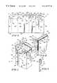
- FIG. 1is a front perspective view of an assembled bulk-storage bin for peanuts in accordance with the present invention showing large top flaps of two inner cartons being folded and glued back to an outer shell of the bin and to divider walls in the cartons in order to cover exposed flutes and provide bulge resistance;
- FIG. 2is a transverse sectional view of the bin of FIG. 1 taken along line 2 — 2 of FIG. 1, with portions broken away, and showing double-thickness side walls and a double-thickness middle divider, and showing bottom triangle flaps of the bin;
- FIG. 3is a vertical sectional view of the bin of FIG. 1 taken along line 3 — 3 of FIG. 1, with portions broken away, showing the double-thickness side walls and middle divider and also showing the top flaps of each inner carton being folded over the outer shell of the bin and over the divider walls in the cartons;
- FIG. 4is a plan view of a first blank of corrugated material used to form the outer shell of the peanut bin of FIG. 1 showing four panels and a shaded inner flap representing an area which is glued prior to assembly;
- FIG. 5is a perspective assembly view showing folding and formation of the blank shown in FIG. 4 to produce the outer shell of the peanut bin;
- FIG. 6is a plan view of a second blank of corrugated material used to form each of the two inner cartons included in the peanut bin of FIG. 1 showing four panels each appended to a fold-over top flap;
- FIG. 7is a perspective assembly view of the second blank of FIG. 6 as it is being folded and formed to produce one of the inner cartons;
- FIG. 8is an enlarged view of a portion of the inner carton shown in FIG. 7, with portions broken away, showing a thin liner (covered with adhesive) that is arranged in order to be folded over a fluted edge of the corrugated material to close openings in the flutes of the corrugated material;
- FIG. 9is a sectional view taken along line 9 — 9 of FIG. 8 showing the liner after the liner has been folded down over the edge in order to cover the exposed fluting;
- FIG. 10is a perspective assembly view of two inner cartons formed from two of the second blanks shown in FIG. 6 and the outer shell formed from the first blank shown in FIG. 4 showing the inner cartons being installed within the outer shell in order to provide a bulk-storage peanut bin.
- Container 10is formed to include two receptacles 11 and 12 sized to receive and store bulk quantities of peanuts or other goods as shown in FIG. 1 .
- Container 10includes a bin 13 formed to include a carton-receiving region 23 and first and second cartons 14 , 15 configured to fit into the carton-receiving region 23 and provide the first and second receptacles 11 , 12 as shown in FIG. 10 .
- the cartons 14 , 15lie in side-by-side relation in bin 13 and outer walls of cartons 14 , 15 are positioned to lie adjacent to inner walls of bin 13 .
- Bin 13is made of a corrugated material and includes a top edge 16 shown in FIG. 10 formed to include top edge openings exposing flutes contained in the corrugated material used to make bin 13 .
- Each of cartons 14 , 15includes top flaps which are arranged as shown in FIGS. 1 and 10 to cover the top edge openings in top edge 16 of bin 13 when the cartons 14 , 15 are mounted in the carton-receiving space 23 of bin 13 as shown in FIG. 1 to block flow of peanuts or peanut parts or shells into the flutes during loading of such items into the peanut receptacles 11 , 12 formed in first and second containers 14 , 15 .
- Each carton 14 , 15is also made of a corrugated material.
- Other top flaps included in the cartons 14 , 15cooperate to cover top edge openings formed in top edge 17 of first carton 14 and top edge 18 of second carton 15 to block flow of peanuts or peanut parts or shells into flutes contained in the corrugated material used to make cartons 14 , 15 and exposed by top edge openings formed in top edges 17 , 18 .
- the top flaps included in first and second cartons 14 , 15cooperate to keep foodstuffs out of the flutes in the corrugated material used to form bin 13 and first and second cartons 14 , 15 .
- Bin 13is made from a first blank 25 of corrugated material, as shown in FIG. 4, and each inner carton 14 , 15 is made from a second blank 19 of corrugated material, as shown in FIG. 6 . Because bin 13 and inner cartons 14 , 15 are used in combination to form storage container 10 , storage container 10 includes four double-thickness side walls 20 , 22 , 24 , 26 , as shown in FIGS. 2 and 3. A double-thickness middle divider 28 is also formed by positioning first carton 14 in side-by-side relation to second carton 15 in the carton-receiving space 23 formed in bin 13 so that a first divider wall included in first carton 14 cooperates with a second divider wall included in second carton 15 to form middle divider 28 .
- bin blank 25is formed to include first, second, third, and fourth bin panels 32 , 34 , 36 , 38 .
- Bin panels 32 , 34 , 36 , 38are arranged in series when folded relative to one another as shown in FIG. 5 to form a bin wall 21 to define a carton-receiving space 23 therebetween.
- First bin panel 32is appended to second bin panel 34 by a double fold line 40
- second bin panel 34is appended to third bin panel 36 by a single fold line 42
- third bin panel 36is appended to fourth bin panel 38 by a double fold line 44 .
- Bin blank 16is also formed to include panels which cooperate to form a floor under bin wall 21 .
- a first outside bottom panel 46is attached to first bin panel 32 by a fold line 48 .
- a left bottom panel 50is attached to second bin panel 34 by a fold line 52 and is also attached to outside bottom panel 46 by a fold line 54 , as shown in FIG. 4.
- a second outside bottom panel 56is attached to third bin panel 36 along a fold line 58 and is also coupled to left bottom panel 50 along a fold line 60 .
- a right bottom panel 62is attached to fourth bin panel 38 along a fold line 64 and is attached to second outside bottom panel 56 along a fold line 65 .
- Inner flaps 66 , 67are provided so that inner flap 66 is attached to first wall panel 32 and inner flap 67 is attached to outside bottom panel 46 .
- Inner flap 66is attached by a fold line 68 and inner flap 67 is attached by a fold line 70 .
- Inner flaps 66 , 67are shown, by the speckled or shaded area, to be glued prior to assembly.
- bin blank 25is folded along vertical fold lines 40 , 42 , 44 so that inner flap 66 may be glued to an inside surface (not shown) of fourth bin panel 38 as indicated by arrow 72 .
- Left and right bottom panels 50 , 62are folded inward along fold lines 52 , 64 , respectively, as shown by arrows 74 .
- side tabs 76 of the first and second outside bottom panels 46 , 56are urged to fold along fold lines 78 .
- This inward foldingis represented by arrows 80 , as shown in FIG. 5 .
- Inner flap 67is glued to an inside surface (not shown) of right bottom panel 62 as indicated by arrow 82 .
- carton blank 19is formed to include a first end carton panel 110 , a first side carton panel 112 , a second end carton panel 114 , a second side carton panel 116 , and a side flap 118 .
- Second side carton panel 116 and side flap 118cooperate to define a divider wall once a carton is formed from carton blank 19 , and that carton is placed in the carton-receiving space 23 in bin 13 .
- Side flap 118is attached to first end panel 110 along a fold line 120 .
- First end carton panel 110is attached to first side carton panel 112 along a fold line 122
- first side carton panel 112is similarly attached to second end carton panel 114 along a fold line 124
- second end carton panel 114is attached to second side carton panel 116 along a fold line 126 .
- Carton blank 19also includes four top flaps 101 , 102 , 103 , 104 appended to carton panels 110 , 112 , 114 , 116 as shown, for example, in FIGS. 6 and 7.
- a first top flap 102is appended to first side carton panel 112 .
- First top flap 102includes a mount panel 132 and an edge cover 133 positioned to interconnect mount panel 132 to first side carton panel 112 .
- First top flap 102is also formed to include a first fold line 113 intermediate first side carton panel 112 and edge cover 133 to facilitate pivotable movement of edge cover 133 about a first fold axis defined by first fold line 113 .
- First top flap 102further includes a second fold line 131 intermediate edge cover 133 and mount panel 132 to facilitate pivotable movement of mount panel 132 relative to edge cover 133 about a second pivot axis defined by second fold line 131 .
- Carton blank 19also includes a second top flap 101 appended to first end carton panel 110 at fold line 111 , a third top flap 103 appended to second end carton panel 114 at fold line 115 , and a fourth top flap 104 appended to the second side carton panel 116 included in divider wall 116 , 118 at fold line 117 as shown in FIGS. 6 and 7.
- Second top flap 101includes edge cover 129 appended to first end carton panel 110 at fold line 111 and to a mount panel 128 at fold line 127 .
- Third top flap 103includes edge cover 137 appended to second end carton panel 114 at fold line 115 and to a mount panel 136 at fold line 135 .
- Fourth top flap 104includes edge cover 141 appended to second side carton panel 116 at fold line 117 and to a mount panel 140 at fold line 139 .
- carton blank 19is folded along vertical fold lines 120 , 122 , 124 , 126 so that an outside edge 146 of side flap 118 is positioned to align with and engage an outside edge 148 of second side carton panel 116 .
- side flap 118 and second side carton panel 116are folded toward each other along respective fold lines 120 , 126 .
- top flap 103includes a distal edge 152 formed to include a distal edge opening exposing flutes 156 contained in the corrugated material used to make top flap 103 .
- Liner 144includes an inner portion 145 , an outer portion 147 , and an edge portion 149 interconnecting the inner and outer portions 145 , 147 and covering the distal edge openings and the flutes 156 therein.
- peanut container 10is assembled by placing two inner cartons 14 , 15 within the container-receiving region 23 of bin 13 , as shown by arrows 155 .
- Inner cartons 14 , 15are placed within bin 13 so that first side panel 112 of inner cartons 14 is positioned to lie adjacent to and in engagement with bin panel 32 and first side carton panel 112 of inner carton 15 is positioned to lie adjacent to and in engagement with bin panel 36 .
- Both inner cartons 14 , 15are placed within carton-receiving region 23 of bin 13 and moved in direction 155 until a bottom edge 157 of each inner carton 14 , 15 engages left and right bottom panels 50 , 62 of bin 13 .
- Each second side carton panel 116 and side flap 118 of inner cartons 14 , 15are positioned to lie adjacent to and in engagement with each other in order to form middle divider 28 , as shown in FIGS. 2 and 3.
- Inner cartons 14 , 15are glued to each other and to an inside surface of each wall panel 32 , 34 , 36 , 38 of bin 13 .
- top flaps 101 , 102 , and 103are folded over the top edge 16 of bin 13 in order to provide extra bulge resistance and to cover exposed fluting of bin 13 .
- top flap 102is folded in direction 158 and mount panel 132 is coupled (e.g., glued or stapled) to bin wall 32 so that edge portion 133 covers the exposed flutes in top edge 16 of bin wall 32 .
- Top flap 101is folded in direction 160 and mount panel 128 is coupled to bin wall 38 so that edge portion 129 covers a first portion of the exposed flutes in top edge 16 of bin wall 38 .
- Top flap 103is folded in direction 162 and mount panel 136 is coupled to bin wall 34 so that edge portion 137 covers a first portion of the exposed flutes in top edge 16 of bin wall 34 .
- top flap 102is folded in direction 258 and mount panel 132 is coupled to bin wall 36 so that edge portion 133 covers the exposed flutes in top edge 16 of bin wall 36 .
- Top flap 103is folded in direction 160 and mount panel 136 is coupled to bin wall 38 so that edge portion 137 covers a remaining second portion of exposed flutes in top edge 16 of bin wall 38 .
- Top flap 101is folded in direction 162 and mount panel 128 is coupled to bin wall 34 so that edge portion 129 covers a remaining second portion of exposed flutes in top edge 16 of bin wall 34 .
- top flap 104 of first carton 14is folded in direction 258 and mount panel 140 is coupled to a second divider wall 116 , 118 in second carton 15 so that edge portion 141 covers exposed flutes in top edge 18 of second divider wall 116 , 118 .
- Top flap 104 of second carton 15is folded in direction 158 and mount panel 140 is coupled to a first divider wall 116 , 118 in first carton so that edge portion 141 covers exposed flutes in top edge 17 of first divider wall 116 , 118 .
- fully assembled peanut storage container 10is formed to include double-thickness side walls 20 , 22 , 24 , 26 having top flaps 101 , 102 , 103 , 104 folded over to act as reinforcement for side walls 20 , 22 , 24 , 26 .
- a first side wall 20is formed by bin panel 32 of bin 13 and first side carton panel 112 of inner carton 14 .
- a second side wall 22is formed by bin panel 36 of bin 13 and first side carton panel 112 of inner carton 15 .
- a third side wall 24as shown in FIG.
- Middle divider 28is formed to have a double-thickness with added reinforcement from top flaps 104 . Double-thickness side walls 20 , 22 , 24 , 26 are provided to increase the stacking strength of storage container 10 so that storage container 10 may be stacked on top of each other during shipping.
- Top flaps 101 , 102 , 103 , 104also cooperate to increase the bulge resistance of container 10 while acting to cover the exposed fluting of bin panels 32 , 34 , 36 , 38 of bin 13 .
- Thin liners 144are provided to cover fluting 156 of exposed distal edges 152 of top flaps 101 , 102 , 103 , 104 .
Landscapes
- Engineering & Computer Science (AREA)
- Mechanical Engineering (AREA)
- Cartons (AREA)
Abstract
Description
Claims (35)
Priority Applications (1)
| Application Number | Priority Date | Filing Date | Title |
|---|---|---|---|
| US09/378,095US6189777B1 (en) | 1998-08-20 | 1999-08-20 | Bulk-storage bin for peanuts |
Applications Claiming Priority (2)
| Application Number | Priority Date | Filing Date | Title |
|---|---|---|---|
| US9730898P | 1998-08-20 | 1998-08-20 | |
| US09/378,095US6189777B1 (en) | 1998-08-20 | 1999-08-20 | Bulk-storage bin for peanuts |
Publications (1)
| Publication Number | Publication Date |
|---|---|
| US6189777B1true US6189777B1 (en) | 2001-02-20 |
Family
ID=26793104
Family Applications (1)
| Application Number | Title | Priority Date | Filing Date |
|---|---|---|---|
| US09/378,095Expired - Fee RelatedUS6189777B1 (en) | 1998-08-20 | 1999-08-20 | Bulk-storage bin for peanuts |
Country Status (1)
| Country | Link |
|---|---|
| US (1) | US6189777B1 (en) |
Cited By (18)
| Publication number | Priority date | Publication date | Assignee | Title |
|---|---|---|---|---|
| US20030144121A1 (en)* | 2001-12-14 | 2003-07-31 | Walsh Joseph C. | Packages, blanks for making packages and associated methods and apparatus |
| US20060283927A1 (en)* | 2002-12-13 | 2006-12-21 | Walsh Joseph C | Packages, blank for making packages and associated methods |
| US20060283928A1 (en)* | 2002-12-13 | 2006-12-21 | Walsh Joseph C | Packages, blanks for making packages and associated methods |
| US20070051085A1 (en)* | 2005-08-23 | 2007-03-08 | Woodland Power Products | Systems and methods for collecting soil and lawn debris |
| US20070278282A1 (en)* | 2006-06-01 | 2007-12-06 | Innovative Packaging Designs L.P. | Improved display ready container |
| US20090151195A1 (en)* | 2007-12-17 | 2009-06-18 | Nike, Inc. | Method For Inflating A Fluid-Filled Chamber |
| US20090302097A1 (en)* | 2008-06-05 | 2009-12-10 | Vincent Richard A | Drawer Box Stabilizing System |
| US20100000672A1 (en)* | 2007-02-23 | 2010-01-07 | Fogle James C | Reinforced carton and methods of making carton blanks |
| US7717322B2 (en) | 2005-06-08 | 2010-05-18 | Graphic Packaging International, Inc. | Packages, blanks for making packages and associated methods |
| US20110127318A1 (en)* | 2009-11-30 | 2011-06-02 | International Paper Company | Interleaved spine container |
| US8196805B2 (en) | 2006-05-18 | 2012-06-12 | Graphic Packaging International, Inc. | Cartons with liquid-tight receptacles |
| US8727204B2 (en) | 2009-11-16 | 2014-05-20 | Graphic Packaging International, Inc. | Expandable carton |
| US10124947B2 (en) | 2014-06-23 | 2018-11-13 | Graphic Packaging International, Llc | Carton with dispensing features |
| US20190248538A1 (en)* | 2018-02-13 | 2019-08-15 | Assograph Italia S.R.L. | Partition and cover structure that can be accommodated in a shoebox, shoebox including said structure and foldable element for obtaining said structure |
| US10737824B2 (en) | 2016-11-14 | 2020-08-11 | Graphic Packaging International, Llc | Reconfigurable carton and package |
| US20240043164A1 (en)* | 2022-08-05 | 2024-02-08 | Wistron Neweb Corporation | Buffer structure, packaging set, and buffer structure forming method |
| US20240425258A1 (en)* | 2021-10-08 | 2024-12-26 | Vkr Holding A/S | Packed roof window product, a method for packing a packed roof window product, and a method of unpacking a packed roof window product |
| US12428193B2 (en) | 2021-10-08 | 2025-09-30 | Vkr Holding A/S | Packed roof window products |
Citations (10)
| Publication number | Priority date | Publication date | Assignee | Title |
|---|---|---|---|---|
| US3063615A (en)* | 1960-07-26 | 1962-11-13 | Corrobilt Container Co | Corrugated container and method of producing same |
| US3701466A (en)* | 1971-04-12 | 1972-10-31 | Continental Can Co | Shipping container with emptying chute |
| US3744702A (en) | 1972-01-26 | 1973-07-10 | Inland Container Corp | Multi-ply container |
| US4037775A (en)* | 1976-02-18 | 1977-07-26 | Olinkraft, Inc. | Bulk reinforced laminated container |
| US4091983A (en) | 1976-07-01 | 1978-05-30 | Olinkraft, Inc. | Bulk container with partial bellows bottom |
| US4154387A (en) | 1976-06-10 | 1979-05-15 | Olinkraft, Inc. | Two-cell bulk container with partial bellows bottom |
| US4174803A (en)* | 1977-07-12 | 1979-11-20 | Inland Container Corporation | Multicell corrugated bulk container |
| US4189086A (en) | 1976-06-10 | 1980-02-19 | Olinkraft, Inc. | Assembled and folded blank for bulk container with partial bellows bottom |
| US4351471A (en)* | 1981-01-27 | 1982-09-28 | Weyerhaeuser Company | Dual cell laminated container |
| US4371109A (en)* | 1981-05-22 | 1983-02-01 | Container Corporation Of America | Two-cell bulk container tubes |
- 1999
- 1999-08-20USUS09/378,095patent/US6189777B1/ennot_activeExpired - Fee Related
Patent Citations (10)
| Publication number | Priority date | Publication date | Assignee | Title |
|---|---|---|---|---|
| US3063615A (en)* | 1960-07-26 | 1962-11-13 | Corrobilt Container Co | Corrugated container and method of producing same |
| US3701466A (en)* | 1971-04-12 | 1972-10-31 | Continental Can Co | Shipping container with emptying chute |
| US3744702A (en) | 1972-01-26 | 1973-07-10 | Inland Container Corp | Multi-ply container |
| US4037775A (en)* | 1976-02-18 | 1977-07-26 | Olinkraft, Inc. | Bulk reinforced laminated container |
| US4154387A (en) | 1976-06-10 | 1979-05-15 | Olinkraft, Inc. | Two-cell bulk container with partial bellows bottom |
| US4189086A (en) | 1976-06-10 | 1980-02-19 | Olinkraft, Inc. | Assembled and folded blank for bulk container with partial bellows bottom |
| US4091983A (en) | 1976-07-01 | 1978-05-30 | Olinkraft, Inc. | Bulk container with partial bellows bottom |
| US4174803A (en)* | 1977-07-12 | 1979-11-20 | Inland Container Corporation | Multicell corrugated bulk container |
| US4351471A (en)* | 1981-01-27 | 1982-09-28 | Weyerhaeuser Company | Dual cell laminated container |
| US4371109A (en)* | 1981-05-22 | 1983-02-01 | Container Corporation Of America | Two-cell bulk container tubes |
Cited By (28)
| Publication number | Priority date | Publication date | Assignee | Title |
|---|---|---|---|---|
| US8025618B2 (en) | 2001-12-14 | 2011-09-27 | Graphic Packaging International, Inc. | Packages, blanks for making packages and associated methods and apparatus |
| US20030144121A1 (en)* | 2001-12-14 | 2003-07-31 | Walsh Joseph C. | Packages, blanks for making packages and associated methods and apparatus |
| US20060283927A1 (en)* | 2002-12-13 | 2006-12-21 | Walsh Joseph C | Packages, blank for making packages and associated methods |
| US20060283928A1 (en)* | 2002-12-13 | 2006-12-21 | Walsh Joseph C | Packages, blanks for making packages and associated methods |
| US7658318B2 (en) | 2002-12-13 | 2010-02-09 | Graphic Packaging International, Inc. | Packages, blanks for making packages and associated methods |
| US7717322B2 (en) | 2005-06-08 | 2010-05-18 | Graphic Packaging International, Inc. | Packages, blanks for making packages and associated methods |
| US20070051085A1 (en)* | 2005-08-23 | 2007-03-08 | Woodland Power Products | Systems and methods for collecting soil and lawn debris |
| US8196805B2 (en) | 2006-05-18 | 2012-06-12 | Graphic Packaging International, Inc. | Cartons with liquid-tight receptacles |
| US20070278282A1 (en)* | 2006-06-01 | 2007-12-06 | Innovative Packaging Designs L.P. | Improved display ready container |
| US8746543B2 (en)* | 2006-06-01 | 2014-06-10 | Innovative Packaging Designs L.P. | Display ready container |
| US8226794B2 (en) | 2007-02-23 | 2012-07-24 | Graphic Packaging International, Inc. | Reinforced carton and methods of making carton blanks |
| US20100000672A1 (en)* | 2007-02-23 | 2010-01-07 | Fogle James C | Reinforced carton and methods of making carton blanks |
| US20090151195A1 (en)* | 2007-12-17 | 2009-06-18 | Nike, Inc. | Method For Inflating A Fluid-Filled Chamber |
| US20090302097A1 (en)* | 2008-06-05 | 2009-12-10 | Vincent Richard A | Drawer Box Stabilizing System |
| US8820620B2 (en)* | 2008-06-05 | 2014-09-02 | Richard A. Vincent | Drawer box stabilizing system |
| US8727204B2 (en) | 2009-11-16 | 2014-05-20 | Graphic Packaging International, Inc. | Expandable carton |
| US9113648B2 (en) | 2009-11-16 | 2015-08-25 | Graphic Packaging International, Inc. | Expandable carton |
| US20110127318A1 (en)* | 2009-11-30 | 2011-06-02 | International Paper Company | Interleaved spine container |
| US8191762B2 (en)* | 2009-11-30 | 2012-06-05 | International Paper Company | Interleaved spine container |
| US10124947B2 (en) | 2014-06-23 | 2018-11-13 | Graphic Packaging International, Llc | Carton with dispensing features |
| US10562687B2 (en) | 2014-06-23 | 2020-02-18 | Graphic Packaging International, Llc | Carton with dispensing features |
| US10737824B2 (en) | 2016-11-14 | 2020-08-11 | Graphic Packaging International, Llc | Reconfigurable carton and package |
| US20190248538A1 (en)* | 2018-02-13 | 2019-08-15 | Assograph Italia S.R.L. | Partition and cover structure that can be accommodated in a shoebox, shoebox including said structure and foldable element for obtaining said structure |
| US10703529B2 (en)* | 2018-02-13 | 2020-07-07 | Assograph Italia S.R.L. | Partition and cover structure that can be accommodated in a shoebox, shoebox including said structure and foldable element for obtaining said structure |
| US20240425258A1 (en)* | 2021-10-08 | 2024-12-26 | Vkr Holding A/S | Packed roof window product, a method for packing a packed roof window product, and a method of unpacking a packed roof window product |
| US12428193B2 (en) | 2021-10-08 | 2025-09-30 | Vkr Holding A/S | Packed roof window products |
| US20240043164A1 (en)* | 2022-08-05 | 2024-02-08 | Wistron Neweb Corporation | Buffer structure, packaging set, and buffer structure forming method |
| US12312133B2 (en)* | 2022-08-05 | 2025-05-27 | Wistron Neweb Corporation | Buffer structure, packaging set, and buffer structure forming method |
Similar Documents
| Publication | Publication Date | Title |
|---|---|---|
| US6189777B1 (en) | Bulk-storage bin for peanuts | |
| US5361976A (en) | Stackable package | |
| US6296178B1 (en) | Container with triangular corner posts | |
| US4380314A (en) | Box type carton with hinged lid and one piece reinforced insert | |
| US4089417A (en) | Flap lock bulk bin | |
| US4531669A (en) | Interlock between telescoping cover and tray | |
| US4549690A (en) | Collapsible bottom structure for eight-sided container | |
| US5524815A (en) | Plural-compartment display carton with locking bottom and center support | |
| US7837089B2 (en) | Bulk material box | |
| US4736885A (en) | Polygonal bulk container | |
| US2982465A (en) | 6 cornered glued box with cover lock | |
| US4383636A (en) | Container | |
| US6464131B1 (en) | Packing box design | |
| US7467743B1 (en) | Container having self-locking structure to provide added stability | |
| US20100101977A1 (en) | Stackable Packaging For Lipped Containers | |
| US4046307A (en) | Two cell bulk container | |
| HU211209B (en) | Carton for packing cylindrical boxes | |
| US4477015A (en) | Two-piece, self-locking container | |
| US20060060643A1 (en) | Display containers with removable panel | |
| US6029885A (en) | Rapid assembly box | |
| US4369914A (en) | Box type carton with hinged lid | |
| US4214695A (en) | One-piece reinforced container | |
| US4174803A (en) | Multicell corrugated bulk container | |
| US4129247A (en) | Die-cut carton with built-in fillers | |
| US5447269A (en) | Multiple unit box and blank therefor |
Legal Events
| Date | Code | Title | Description |
|---|---|---|---|
| AS | Assignment | Owner name:INLAND PAPERBOARD AND PACKAGING, INC., INDIANA Free format text:ASSIGNMENT OF ASSIGNORS INTEREST;ASSIGNORS:HUTCHINSON, STEVE L.;FRANKLIN, TROY M.;REEL/FRAME:010631/0134;SIGNING DATES FROM 19991105 TO 20000119 | |
| FEPP | Fee payment procedure | Free format text:PAYOR NUMBER ASSIGNED (ORIGINAL EVENT CODE: ASPN); ENTITY STATUS OF PATENT OWNER: LARGE ENTITY | |
| FPAY | Fee payment | Year of fee payment:4 | |
| FEPP | Fee payment procedure | Free format text:PAYER NUMBER DE-ASSIGNED (ORIGINAL EVENT CODE: RMPN); ENTITY STATUS OF PATENT OWNER: LARGE ENTITY Free format text:PAYOR NUMBER ASSIGNED (ORIGINAL EVENT CODE: ASPN); ENTITY STATUS OF PATENT OWNER: LARGE ENTITY | |
| AS | Assignment | Owner name:TEMPLE-INLAND FOREST PRODUCTS CORPORATION, TEXAS Free format text:MERGER;ASSIGNOR:INLAND PAPERBOARD AND PACKAGING, INC.;REEL/FRAME:020963/0067 Effective date:20041215 Owner name:TIN INC., TEXAS Free format text:CHANGE OF NAME;ASSIGNOR:TEMPLE-INLAND FOREST PRODUCTS CORPORATION;REEL/FRAME:020963/0076 Effective date:20041231 | |
| REMI | Maintenance fee reminder mailed | ||
| LAPS | Lapse for failure to pay maintenance fees | ||
| STCH | Information on status: patent discontinuation | Free format text:PATENT EXPIRED DUE TO NONPAYMENT OF MAINTENANCE FEES UNDER 37 CFR 1.362 | |
| FP | Lapsed due to failure to pay maintenance fee | Effective date:20090220 |