US6189252B1 - Picture frame corner connecting element - Google Patents
Picture frame corner connecting elementDownload PDFInfo
- Publication number
- US6189252B1 US6189252B1US09/368,597US36859799AUS6189252B1US 6189252 B1US6189252 B1US 6189252B1US 36859799 AUS36859799 AUS 36859799AUS 6189252 B1US6189252 B1US 6189252B1
- Authority
- US
- United States
- Prior art keywords
- frame
- frame elements
- adjacent
- mitred
- plate
- Prior art date
- Legal status (The legal status is an assumption and is not a legal conclusion. Google has not performed a legal analysis and makes no representation as to the accuracy of the status listed.)
- Expired - Lifetime
Links
- 238000000465mouldingMethods0.000abstractdescription3
- HCHKCACWOHOZIP-UHFFFAOYSA-NZincChemical compound[Zn]HCHKCACWOHOZIP-UHFFFAOYSA-N0.000description2
- 230000000295complement effectEffects0.000description2
- 239000000463materialSubstances0.000description2
- 239000002023woodSubstances0.000description2
- 239000011701zincSubstances0.000description2
- 229910052725zincInorganic materials0.000description2
- 239000000853adhesiveSubstances0.000description1
- 230000001070adhesive effectEffects0.000description1
- 238000000034methodMethods0.000description1
Images
Classifications
- A—HUMAN NECESSITIES
- A47—FURNITURE; DOMESTIC ARTICLES OR APPLIANCES; COFFEE MILLS; SPICE MILLS; SUCTION CLEANERS IN GENERAL
- A47G—HOUSEHOLD OR TABLE EQUIPMENT
- A47G1/00—Mirrors; Picture frames or the like, e.g. provided with heating, lighting or ventilating means
- A47G1/06—Picture frames
- A47G1/10—Corner clips or corner-connecting appliances for frames
- F—MECHANICAL ENGINEERING; LIGHTING; HEATING; WEAPONS; BLASTING
- F16—ENGINEERING ELEMENTS AND UNITS; GENERAL MEASURES FOR PRODUCING AND MAINTAINING EFFECTIVE FUNCTIONING OF MACHINES OR INSTALLATIONS; THERMAL INSULATION IN GENERAL
- F16B—DEVICES FOR FASTENING OR SECURING CONSTRUCTIONAL ELEMENTS OR MACHINE PARTS TOGETHER, e.g. NAILS, BOLTS, CIRCLIPS, CLAMPS, CLIPS OR WEDGES; JOINTS OR JOINTING
- F16B2200/00—Constructional details of connections not covered for in other groups of this subclass
- F16B2200/65—Miter joints
Definitions
- This inventionrelates to picture frames and, more particularly, to Hicks type frames.
- a picture framecommonly known as a Hicks frame or moulding, is a popular frame, particularly for use with primitive art.
- a Hicks frameindividual frame elements are connected at a corner, for example, by means of a lap or tenon joint.
- a corner blockcan be adhered to the frame in each corner thereby hiding the joint, or a corner block can be machined to become the junction for the separate legs resulting in an attractive frame with decorative corners.
- the present inventionprovides a picture frame in the Hicks style which can be easily assembled by a framer and which requires no tenon or lap joints.
- a picture framecomprises four framed elements joined together at mitred edges.
- a connector grooveextends across each of the mitred junctions and is accessible from the front of the frame.
- Corner pieceswhich simulate the corner pieces used in a Hicks frame are provided at each corner of the frame. Each corner pieces overlies the junction between two adjacent frame elements.
- each corner pieceincludes a connector which engages the connecting grooves between adjacent frame elements to secure the frame when the corner piece is secured to the frame.
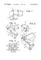
- FIG. 1is a perspective view of a prior art Hicks frame
- FIG. 2is an exploded perspective view of the corner of a frame showing how the parts are assembled
- FIG. 3is a perspective view of the corner of a frame after it has been assembled in accordance with invention
- FIG. 4is a sectional view along the line 4 — 4 of FIG. 3;
- FIG. 5is a sectional line along the line 5 — 5 of FIG. 3;
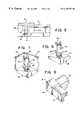
- FIG. 6is a perspective view of a corner piece in accordance with the preferred embodiment of the invention.
- FIG. 7is a perspective view of an alternative embodiment in accordance with the invention.
- FIG. 8is a perspective view showing the embodiment of FIG. 7 attached to a frame.
- FIG. 1shows a conventional Hicks type picture frame or moulding. It comprises frame elements 7 having a decorative corner piece 8 in each corner.
- the corner piecemay be purely decorative or, as mentioned above and as shown in FIG. 1, it may comprise a structural element which receives the properly machined ends of the adjacent frame elements. In either event, when viewed from the front, a decorative square block appears in each corner of the frame.
- U.S. Pat. No. 4,742,856 entitled Groove Forming Apparatus And Methoddiscloses a picture frame in which the frame elements are mitred and held in place by means of a connector inserted into grooves cut into the mitred edges of the frame elements.
- the apparatus for cutting the groovesis also shown in U.S. Pat. No. 4,742,856 which is hereby incorporated by reference into this specification.
- the connector and cutting apparatus illustrated in the '856 patentare in commercial use and are known as the Thumbnail system.
- the mitred edges of the frame elementare aligned and a shaped router bit cuts a T-shaped groove partially through the two aligned frame elements.
- the t-shaped groovesare aligned at the back of the frame and the connector (which is H-shaped in cross-section) inserted into the grooves from the back, with only the mitred junction between the frame elements showing in the front.
- the Thumbnail machine as shown in the '856 patentis used to cut a T-shaped groove through the entire frame element.
- two frame elements 10 and 12are shown having abutting mitred edges 10 A and 12 A, respectively.
- a T-shaped groove 14is cut into the mitred face 10 A of frame element 10 and a similar T-shaped groove 16 is cut into the mitred face 12 A of frame element 12 .
- the two T-shaped grooves 14 and 16together form an H-shaped groove as shown.
- the grooves 14 and 16extend through the front or forward facing surface of the frame elements 10 and 12 . In the preferred embodiment, grooves 14 and 16 extend entirely through the frame elements but it is not necessary that the grooves be accessible from the back of the frame.
- a corner piece 18includes a square plate 19 and an integral connector 20 .
- connector 20includes a central web 32 which joins two cross pieces 34 so that the connector is H-shaped in horizontal cross-section.
- Connector 20is the same as the connector illustrated in the '856 patent; however, in the invention, the connector 20 is formed as a unitary member with the plate 19 .
- the plate 19 and connectormay be die cast from zinc.
- the corner piece 18 with the integral connector 20is inserted into the slots 14 and 16 (FIG. 2) clamping the frame elements together.
- the dimensions of the square plate 19correspond to the width of the frame elements.
- the square platecovers the junction of the frame elements and simulates the appearance of a Hicks type frame with a corner piece in each corner overlying the joint between adjacent frame elements.
- the frame elements 10 and 12are shown with a slight bevel such that when the frame is assembled the inner edge of the frame is slightly lower than the outer edge.
- the under surface of the corner piece 18has a complementary shape, i.e., it is beveled in the opposite way so that when the corner piece is inserted, its undersurface, which contacts the outer surfaces of the frame elements 10 and 12 , is flush with the contiguous surfaces. If this were not the case, a gap between the undersurface of the corner piece and the frame elements might be visible. In many situations, the frame elements will be flat (i.e. not beveled), in which case the corner piece also would be flat. If the outer surfaces of the frame elements were more complex, for example including curved surfaces, the corner piece would be formed with a complementary surface to provide a flush fit.
- the frame elements 10 and 12are made from wood and the corner piece 18 is die cast from zinc.
- the connector 20can be separately formed and attached to plate 19 by a suitable adhesive.
- the corner piecein that instance, can be made of wood or any other desirable material which complements the frame elements 10 and 12 .
- the grooves 14 and 16extend through the entire width of the frame elements 10 and 12 , respectively. This provides for the possibility of inserting additional connectors from the back of the frame to assist in securing the frame elements together. Furthermore, although the Thumbnail system is preferred, other connector systems with differently shaped grooves and connectors can also be used.
- FIGS. 7 and 8show an alternative embodiment of the invention in which side flanges 40 are provided on the two outer sides of the corner piece which is otherwise the same as the corner piece illustrated in FIGS. 2-6.
- the side flangesare intended to serve a decorative function.
Landscapes
- Mirrors, Picture Frames, Photograph Stands, And Related Fastening Devices (AREA)
Abstract
Description
Claims (4)
Priority Applications (1)
| Application Number | Priority Date | Filing Date | Title |
|---|---|---|---|
| US09/368,597US6189252B1 (en) | 1999-08-04 | 1999-08-04 | Picture frame corner connecting element |
Applications Claiming Priority (1)
| Application Number | Priority Date | Filing Date | Title |
|---|---|---|---|
| US09/368,597US6189252B1 (en) | 1999-08-04 | 1999-08-04 | Picture frame corner connecting element |
Publications (1)
| Publication Number | Publication Date |
|---|---|
| US6189252B1true US6189252B1 (en) | 2001-02-20 |
Family
ID=23451902
Family Applications (1)
| Application Number | Title | Priority Date | Filing Date |
|---|---|---|---|
| US09/368,597Expired - LifetimeUS6189252B1 (en) | 1999-08-04 | 1999-08-04 | Picture frame corner connecting element |
Country Status (1)
| Country | Link |
|---|---|
| US (1) | US6189252B1 (en) |
Cited By (11)
| Publication number | Priority date | Publication date | Assignee | Title |
|---|---|---|---|---|
| US20030168264A1 (en)* | 2000-10-27 | 2003-09-11 | Gerold Goertzen | Obstacle traversing wheelchair |
| US20060196094A1 (en)* | 2005-02-01 | 2006-09-07 | Robin Sturmthal | Decorative computer monitor frame |
| US20190116995A1 (en)* | 2017-10-24 | 2019-04-25 | Matthew Udermann | Quick Assembly Photo Frame |
| US10813478B2 (en)* | 2016-12-20 | 2020-10-27 | Tracer Imaging Llc | System for retaining an image within a frame |
| US10981415B2 (en) | 2015-07-21 | 2021-04-20 | Tracer Imaging Llc | System for mounting a covering upon a frame |
| RU206012U1 (en)* | 2021-05-24 | 2021-08-16 | Владимир Васильевич Галайко | Collapsible stretcher for canvas |
| US20220078979A1 (en)* | 2020-09-15 | 2022-03-17 | Patrick Scott Brady | Trellis assembly |
| US11419436B2 (en) | 2019-06-19 | 2022-08-23 | Tracer Imaging Llc | Method for retaining a substrate within a frame |
| US11523693B2 (en) | 2020-07-31 | 2022-12-13 | Tracer Imaging Llc | Snap-fit framing system |
| US20220395114A1 (en)* | 2018-02-06 | 2022-12-15 | Mcs Industries, Inc. | Method of assembling a frame |
| US12329297B2 (en) | 2020-07-31 | 2025-06-17 | Tracer Imaging Llc | Framing system and wall pad therefor |
Citations (5)
| Publication number | Priority date | Publication date | Assignee | Title |
|---|---|---|---|---|
| US132114A (en)* | 1872-10-08 | Improvement in frames | ||
| US909080A (en)* | 1907-05-07 | 1909-01-05 | William Goodrow | Frame corner and fastener. |
| US4477990A (en)* | 1982-06-08 | 1984-10-23 | William Sornborger | Picture frame |
| US4913579A (en)* | 1988-10-11 | 1990-04-03 | Campana Technology, Inc. | Decorative panel |
| US4922638A (en)* | 1988-03-11 | 1990-05-08 | Joel Litvak | Decorative modular picture frame |
- 1999
- 1999-08-04USUS09/368,597patent/US6189252B1/ennot_activeExpired - Lifetime
Patent Citations (5)
| Publication number | Priority date | Publication date | Assignee | Title |
|---|---|---|---|---|
| US132114A (en)* | 1872-10-08 | Improvement in frames | ||
| US909080A (en)* | 1907-05-07 | 1909-01-05 | William Goodrow | Frame corner and fastener. |
| US4477990A (en)* | 1982-06-08 | 1984-10-23 | William Sornborger | Picture frame |
| US4922638A (en)* | 1988-03-11 | 1990-05-08 | Joel Litvak | Decorative modular picture frame |
| US4913579A (en)* | 1988-10-11 | 1990-04-03 | Campana Technology, Inc. | Decorative panel |
Cited By (19)
| Publication number | Priority date | Publication date | Assignee | Title |
|---|---|---|---|---|
| US20030168264A1 (en)* | 2000-10-27 | 2003-09-11 | Gerold Goertzen | Obstacle traversing wheelchair |
| US20060196094A1 (en)* | 2005-02-01 | 2006-09-07 | Robin Sturmthal | Decorative computer monitor frame |
| US20070258203A1 (en)* | 2005-02-01 | 2007-11-08 | Robin Sturmthal | Decorative Add-On Frame For An Electronic Monitor |
| US11548315B2 (en) | 2015-07-21 | 2023-01-10 | Tracer Imaging Llc | System for mounting a covering upon a frame |
| US10981415B2 (en) | 2015-07-21 | 2021-04-20 | Tracer Imaging Llc | System for mounting a covering upon a frame |
| US11684185B2 (en) | 2016-12-20 | 2023-06-27 | Tracer Imaging Llc | System for retaining an image within a frame |
| US10813478B2 (en)* | 2016-12-20 | 2020-10-27 | Tracer Imaging Llc | System for retaining an image within a frame |
| US10470595B2 (en)* | 2017-10-24 | 2019-11-12 | Matthew Udermann | Quick assembly photo frame |
| US20190116995A1 (en)* | 2017-10-24 | 2019-04-25 | Matthew Udermann | Quick Assembly Photo Frame |
| US20220395114A1 (en)* | 2018-02-06 | 2022-12-15 | Mcs Industries, Inc. | Method of assembling a frame |
| US12075930B2 (en)* | 2018-02-06 | 2024-09-03 | Mcs Industries, Inc. | Method of assembling a frame |
| US11419436B2 (en) | 2019-06-19 | 2022-08-23 | Tracer Imaging Llc | Method for retaining a substrate within a frame |
| US11553808B2 (en) | 2019-06-19 | 2023-01-17 | Tracer Imaging Llc | System for retaining a substrate within a frame |
| US12364348B2 (en) | 2019-06-19 | 2025-07-22 | Tracer Imaging Llc | System for retaining a substrate within a frame |
| US11523693B2 (en) | 2020-07-31 | 2022-12-13 | Tracer Imaging Llc | Snap-fit framing system |
| US11857091B2 (en) | 2020-07-31 | 2024-01-02 | Tracer Imaging Llc | Snap-fit framing system |
| US12329297B2 (en) | 2020-07-31 | 2025-06-17 | Tracer Imaging Llc | Framing system and wall pad therefor |
| US20220078979A1 (en)* | 2020-09-15 | 2022-03-17 | Patrick Scott Brady | Trellis assembly |
| RU206012U1 (en)* | 2021-05-24 | 2021-08-16 | Владимир Васильевич Галайко | Collapsible stretcher for canvas |
Similar Documents
| Publication | Publication Date | Title |
|---|---|---|
| USD463623S1 (en) | Attachment for a hair cutting machine | |
| US6189252B1 (en) | Picture frame corner connecting element | |
| US4279455A (en) | Drawer assembly | |
| US4839974A (en) | Closed decoration frame | |
| CA2293141C (en) | Method for making corners for laminate and veneer countertops | |
| USD399354S (en) | Chair | |
| USD417826S (en) | Snow tool blade | |
| US20020092632A1 (en) | Corner for screen | |
| USD426265S (en) | Poetry magnet board | |
| CA2694195C (en) | A frame for mounting to a premounted mirror | |
| GB2127741A (en) | Picture frames | |
| GB2079598A (en) | Picture frame | |
| USD367715S (en) | Building element | |
| USD409425S (en) | Corner shelf | |
| USD382045S (en) | Plumbing handle | |
| US4740397A (en) | Composite structural frame component | |
| US20050102879A1 (en) | Decorative corner piece for connecting mitered frame sections together | |
| USD284909S (en) | Picture frame | |
| KR200274850Y1 (en) | Prefabricated picture frame | |
| USD369028S (en) | Chair | |
| JPH0742366Y2 (en) | Picture frame | |
| JPH077515Y2 (en) | Structure of joints between decorative boards | |
| USD408264S (en) | Pin for joining components of a window muntin bar assembly | |
| USD294999S (en) | Connector for a picture frame | |
| JPS6018504Y2 (en) | Decorative veneer |
Legal Events
| Date | Code | Title | Description |
|---|---|---|---|
| AS | Assignment | Owner name:NIELSEN & BAINBRIDGE L.L.C., NEW JERSEY Free format text:ASSIGNMENT OF ASSIGNORS INTEREST;ASSIGNORS:DOWZALL, MARTIN;HOUSSIAN, VAZGEN;REEL/FRAME:010159/0801 Effective date:19990727 | |
| STCF | Information on status: patent grant | Free format text:PATENTED CASE | |
| FPAY | Fee payment | Year of fee payment:4 | |
| AS | Assignment | Owner name:NATIONAL CITY BANK, OHIO Free format text:SECURITY AGREEMENT;ASSIGNOR:NIELSON & BAINBRIDGE, LLC;REEL/FRAME:017982/0084 Effective date:20060525 | |
| FPAY | Fee payment | Year of fee payment:8 | |
| AS | Assignment | Owner name:PNC BANK, NATIONAL ASSOCIATION, PENNSYLVANIA Free format text:SECURITY AGREEMENT;ASSIGNOR:NIELSEN & BAINBRIDGE, LLC;REEL/FRAME:026113/0753 Effective date:20110412 | |
| FPAY | Fee payment | Year of fee payment:12 | |
| AS | Assignment | Owner name:GENERAL ELECTRIC CAPITAL CORPORATION, AS AGENT, IL Free format text:SECURITY AGREEMENT;ASSIGNOR:NIELSEN & BAINBRIDGE, LLC;REEL/FRAME:031890/0576 Effective date:20131230 | |
| AS | Assignment | Owner name:NIELSEN & BAINBRIDGE, LLC, NEW JERSEY Free format text:RELEASE BY SECURED PARTY;ASSIGNOR:PNC BANK, NATIONAL ASSOCIATION;REEL/FRAME:031894/0275 Effective date:20131230 | |
| AS | Assignment | Owner name:GENERAL ELECTRIC CAPITAL CORPORATION, AS FIRST LIE Free format text:SECURITY INTEREST;ASSIGNOR:NIELSEN & BAINBRIDGE, LLC;REEL/FRAME:033558/0513 Effective date:20140815 | |
| AS | Assignment | Owner name:NIELSEN & BAINBRIDGE, LLC, TEXAS Free format text:RELEASE OF SECURITY INTEREST;ASSIGNOR:GENERAL ELECTRIC CAPITAL CORPORATION, AS AGENT;REEL/FRAME:033570/0393 Effective date:20140815 Owner name:GENERAL ELECTRIC CAPITAL CORPORATION, AS SECOND LI Free format text:SECURITY INTEREST;ASSIGNOR:NIELSEN & BAINBRIDGE, LLC;REEL/FRAME:033570/0222 Effective date:20140815 | |
| AS | Assignment | Owner name:ANTARES CAPITAL LP, ILLINOIS Free format text:SECURITY AGREEMENT;ASSIGNOR:GENERAL ELECTRIC CAPITAL CORPORATION;REEL/FRAME:036665/0268 Effective date:20150821 Owner name:ANTARES CAPITAL LP, ILLINOIS Free format text:SECURITY AGREEMENT;ASSIGNOR:GENERAL ELECTRIC CAPITAL CORPORATION;REEL/FRAME:036665/0127 Effective date:20150821 Owner name:ANTARES CAPITAL LP, ILLINOIS Free format text:ASSIGNMENT OF INTELLECTUAL PROPERTY SECURITY AGREEMENT;ASSIGNOR:GENERAL ELECTRIC CAPITAL CORPORATION;REEL/FRAME:036665/0127 Effective date:20150821 Owner name:ANTARES CAPITAL LP, ILLINOIS Free format text:ASSIGNMENT OF INTELLECTUAL PROPERTY SECURITY AGREEMENT;ASSIGNOR:GENERAL ELECTRIC CAPITAL CORPORATION;REEL/FRAME:036665/0268 Effective date:20150821 | |
| AS | Assignment | Owner name:WELLS FARGO BANK, NATIONAL ASSOCIATION, GEORGIA Free format text:SECURITY INTEREST;ASSIGNORS:DESIGN SOLUTIONS INTERNATIONAL, INC.;JIMCO LAMP & MANUFACTURING COMPANY;NIELSEN & BAINBRIDGE, LLC;REEL/FRAME:042152/0356 Effective date:20170426 | |
| AS | Assignment | Owner name:DEUTSCHE BANK AG NEW YORK BRANCH, AS FIRST LIEN CO Free format text:SECURITY INTEREST;ASSIGNOR:NIELSEN & BAINBRIDGE, LLC;REEL/FRAME:042165/0545 Effective date:20170426 Owner name:NIELSEN & BAINBRIDGE, LLC, TEXAS Free format text:RELEASE BY SECURED PARTY;ASSIGNOR:ANTARES CAPITAL LP, AS FIRST LIEN AGENT AND AS SUCCESSOR IN INTEREST TO GENERAL ELECTRIC CAPITAL CORPORATION;REEL/FRAME:042165/0583 Effective date:20170426 Owner name:NIELSEN & BAINBRIDGE, LLC, TEXAS Free format text:RELEASE BY SECURED PARTY;ASSIGNOR:ANTARES CAPITAL LP, AS SECOND LIEN AGENT AND AS SUCCESSOR IN INTEREST TO GENERAL ELECTRIC CAPITAL CORPORATION;REEL/FRAME:042165/0623 Effective date:20170426 | |
| AS | Assignment | Owner name:CORTLAND CAPITAL MARKET SERVICES LLC, ILLINOIS Free format text:SECURITY INTEREST;ASSIGNORS:DESIGN SOLUTIONS INTERNATIONAL, INC.;JIMCO LAMP & MANUFACTURING COMPANY;NIELSEN & BAINBRIDGE, LLC;REEL/FRAME:042212/0986 Effective date:20170426 Owner name:NIELSEN & BAINBRIDGE, LLC, NEW JERSEY Free format text:CORRECTIVE ASSIGNMENT TO CORRECT THE ASSIGNEE NAME PREVIOUSLY RECORDED ON REEL 010159 FRAME 0801. ASSIGNOR(S) HEREBY CONFIRMS THE ASSIGNMENT;ASSIGNORS:DOWZALL, MARTIN;HOUSSIAN, VAZGEN;REEL/FRAME:042387/0917 Effective date:19990727 | |
| AS | Assignment | Owner name:NIELSEN & BAINBRIDGE, LLC, TEXAS Free format text:RELEASE OF SECURITY INTEREST RECORDED AT REEL/FRAME 031890/0576;ASSIGNOR:GENERAL ELECTRIC CAPITAL CORPORATION, AS AGENT;REEL/FRAME:054926/0766 Effective date:20140815 |