US6188392B1 - Electronic pen device - Google Patents
Electronic pen deviceDownload PDFInfo
- Publication number
- US6188392B1 US6188392B1US08/884,922US88492297AUS6188392B1US 6188392 B1US6188392 B1US 6188392B1US 88492297 AUS88492297 AUS 88492297AUS 6188392 B1US6188392 B1US 6188392B1
- Authority
- US
- United States
- Prior art keywords
- coupled
- acceleration sensor
- tip
- controller
- housing
- Prior art date
- Legal status (The legal status is an assumption and is not a legal conclusion. Google has not performed a legal analysis and makes no representation as to the accuracy of the status listed.)
- Expired - Lifetime
Links
Images


Classifications
- G—PHYSICS
- G06—COMPUTING OR CALCULATING; COUNTING
- G06F—ELECTRIC DIGITAL DATA PROCESSING
- G06F3/00—Input arrangements for transferring data to be processed into a form capable of being handled by the computer; Output arrangements for transferring data from processing unit to output unit, e.g. interface arrangements
- G06F3/01—Input arrangements or combined input and output arrangements for interaction between user and computer
- G06F3/03—Arrangements for converting the position or the displacement of a member into a coded form
- G06F3/033—Pointing devices displaced or positioned by the user, e.g. mice, trackballs, pens or joysticks; Accessories therefor
- G06F3/0354—Pointing devices displaced or positioned by the user, e.g. mice, trackballs, pens or joysticks; Accessories therefor with detection of 2D relative movements between the device, or an operating part thereof, and a plane or surface, e.g. 2D mice, trackballs, pens or pucks
- G06F3/03545—Pens or stylus
- G—PHYSICS
- G06—COMPUTING OR CALCULATING; COUNTING
- G06F—ELECTRIC DIGITAL DATA PROCESSING
- G06F3/00—Input arrangements for transferring data to be processed into a form capable of being handled by the computer; Output arrangements for transferring data from processing unit to output unit, e.g. interface arrangements
- G06F3/01—Input arrangements or combined input and output arrangements for interaction between user and computer
- G06F3/03—Arrangements for converting the position or the displacement of a member into a coded form
- G06F3/033—Pointing devices displaced or positioned by the user, e.g. mice, trackballs, pens or joysticks; Accessories therefor
- G06F3/038—Control and interface arrangements therefor, e.g. drivers or device-embedded control circuitry
- G06F3/0383—Signal control means within the pointing device
- G—PHYSICS
- G06—COMPUTING OR CALCULATING; COUNTING
- G06V—IMAGE OR VIDEO RECOGNITION OR UNDERSTANDING
- G06V10/00—Arrangements for image or video recognition or understanding
- G06V10/10—Image acquisition
- G06V10/12—Details of acquisition arrangements; Constructional details thereof
Definitions
- the present inventionrelates to devices or systems for entering information into a data processing machine. More specifically, the present invention relates to devices and systems that capture and store information related to hand written or hand drawn text, characters, symbols or graphics.
- a computer systemtypically includes an alphanumeric keyboard that enables users to enter commands and data in a text format to be processed by a data processing machine such as a computer.
- Keyboardsare the most commonly used input devices for computers. However, keyboards require users to develop skills in typing, they are not well suited for entering graphics data, and they are usually tethered to the computer by means of a cable. Additionally, keyboards require users to learn many particular keystroke sequences to invoke corresponding computer commands, requiring more time to implement and more effort to learn.
- mouse pointing devicethat is efficient for invoking particular computer commands. This device is typically connected to the computer by way of an electrical cable and must be used in close proximity to the computer. The mouse pointing device functions satisfactorily for the purpose of initiating particular computer functions, but users regard the device as awkward and imprecise for entering text and graphics data.
- Digitizer tabletsthat involve the use of a flat touch pad which can be touched by a stylus.
- the padsenses the location of the touching object usually by resistance or capacitance disturbances in a field associated with the pad.
- Digitizer tabletsperform well for entering graphics, report absolute position well, but are impractical for entering textual data.
- Certain tabletshave been proposed by which both graphics and textual data could be entered in a computer using a stylus. These devices are typically tethered to the user's computer by an electrical cable, and provide no memory storage to permit autonomous usage. Further, these devices are inconvenient for the user due to their physical dimensions. Most users, would find it desirable to have a computer input device that: is autonomous, i.e. untethered by cable connection to a computer; permits easy and precisely controllable input of both text and graphics data; fits in the hand like a pen or pencil for ease of use; affords memory capacity to store accumulated input of data of most users over the course of a day; and can be carried unobtrusively in a user's pocket.
- an additional dimensionsuch as a third dimension and rotation about each axis in connection with the three dimensions, involved in the motion of the pen input device, must be measured to provide accurate information about two-dimensional tracing on a writing surface in connection with text or graphics input to the computer.
- This additional informationmay, for example, provide information about the Z coordinate or the rotation of a predetermined point of the pen input device in the course of its motion.
- some conventional input deviceshave focused on detecting the motion of the pen in two dimensions.
- the elements measuring the motion of the pen in two dimensionsare placed intermediately pen input device relative to an axis passing through a tip of the pen and free end of the pen located away from the tip. Also, these elements may be placed at the free end of the pen input device.
- the measurement in two directions (X and Y) recorded by these elementsis not accurate as the farther these elements are from the tip of the pen, the more a measurement in the third dimension (Z axis) and measurement of the rotation about each axis is necessary to accurately reflect the motion.
- the rotation of the input device about the tip of the pen and around the axes of the penparticularly poses significant problems in its measurement and “interpretation” thereof with respect to the text or graphics information input to the computer.
- an input devicesuch as a marking device that can use existing paper/tablet as writing surface so that the user of the pen may also see the mark the marking device leaves on the writing surface as the marking device is utilized for text or graphics. It is also desirable to provide a marking device that captures and stores detailed information about the dynamic motion of the marking device as it is used in writing, drawing, and illustration.
- the present inventionprovides a marking device.
- the marking deviceincludes an elongated housing that has a tip configured to contact a surface.
- the MDalso includes a pressure sensor disposed within the housing.
- the pressure sensoris coupled to the tip and is configured to detect when the tip contacts the surface.
- the MDfurther includes first and second acceleration sensors disposed within the housing and adjacent the tip of the MD.
- the first and second acceleration sensorsare configured to sense acceleration of the tip in first and second directions. Responsive to the sensing of acceleration, first and second acceleration sensors generate a signal indicative of acceleration in first and second directions.
- the MDalso includes a conversion device configured to receive first and second signals and convert first and second signals into at least one computer readable signal.
- FIG. 1illustrates an embodiment of a marking device (MD) according to the present invention
- FIG. 2illustrates, in block diagram form, main components included in an embodiment of the MD of the present invention.
- FIG. 3illustrates in a more detailed form main components that may be included in an embodiment of the present invention
- FIG. 4illustrates a portion of an embodiment of the MD according to the present invention close to a tip of the MD
- FIG. 5illustrates a perspective view of a MD according to the present
- FIG. 6illustrates a cross sectional view through lines 6 — 6 shown in FIG. 5;
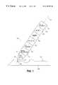
- FIG. 7illustrates an assembly that includes an embodiment of the MD according to the present invention and an embodiment of a docking station according to the present invention.
- FIG. 1illustrates an embodiment of a marking device (MD) 100 (also referred as “pen 100 ”) according to the present invention.
- MD 100includes an elongated housing 102 (hereinafter referred as “housing 102 ”) with a hollow interior that accommodates a plurality of components of MD 100 .
- housing 102may be made of, or have an outer surface made of, a conductive material such as conductive plastic or metal to shield inner components included in housing 102 from electromagnetic noise.
- the components of MD 100may be supported by a support structure (not shown) located inside housing 102 .
- Housing 102has a tip 104 at an end thereof.
- Tip 104is configured to contact a marking surface 106 , which may be a piece of paper, a tablet, or a screen such as the screen of a computer.
- Tip 104may be of a ball-point type in communication with a ball-point ink cartridge (not shown) that may optionally be placed inside housing 102 . It should be understood that it is not necessary that tip 104 communicates with a ball-point ink cartridge or that it includes leads for actually marking surface 106 . In certain applications where it is important to preserve secrecy, it may be desirable that tip 104 does not produce an actual mark on marking surface 106 .
- Tip 104may be attached to a tip holder (not shown) at one end thereof.
- the tip holdermay have at the other end thereof a structure for attaching an ink cartridge or other type of cartridges to communicate with tip 104 .
- Coupled to tip 104is a pressure sensor 108 .
- the pressure sensortypically senses contact or pressure applied by tip 104 when this tip contacts or is pressed against surface 106 .
- pressure sensor 108may be a microswitch, but the present invention is not limited to a microswitch implementing the pressure sensor.
- Pressure sensor 108may also be implemented as a piezo electric pressure transducer known in the art.
- the piezo-electric pressure transducermay have a tubular shape or any other shape disposed in a direction parallel to axis 111 that passes along housing 102 .
- the piezo-electric sensormay have at least one pair of electrodes coupled to a piezo-electric element which may be compressed as a result of the pressure exerted to the tip 104 .
- the piezo-electric transducermay then convey the resulting compression exerted thereto into an electrical signal.
- MD 100further includes first and second acceleration sensors 112 and 113 disposed in housing 102 adjacent tip 104 .
- Acceleration sensors 112 and 113are configured to sense and provide a measure related to acceleration of tip 104 in first and second directions which may be, but are not limited to, X and Y directions in a three-dimensional carthesian system of coordinates.
- the acceleration of tip 104 in first and second directions, the information from the pressure sensor and temporal information related to the sampling of the acceleration sensorsmay be later processed by a processing device to determine speed, position, angular information about the composite acceleration, etc.
- processingmay be based on well established mathematical formulae, well known in the art, from which one may determine, based on acceleration, speed, position, etc.
- first and second acceleration sensorsIn response to the determination of acceleration in first and second directions, first and second acceleration sensors generate first and second signals which may be, but are not limited to, electrical signals.
- the acceleration sensorscapture information about the dynamic motion of MD 100 , i.e., the acceleration in X and Y directions.
- First and second acceleration sensorsmay include solid state devices such as conventional acceleration sensors used in automobile airbags that are made very small so that they may be easily integrated and placed adjacent tip 104 of MD 100 .
- the placement of two acceleration sensors adjacent the tip of the penreduces the need for a third element that detects vertical motion or acceleration in a vertical (Z) direction caused by motion vertical motion of the pen.
- the placement of two acceleration sensors adjacent the tip of the penalso reduces the need for utilizing fourth, fifth, and sixth elements which detect motion or acceleration due to rotation about the X, Y and Z directions.
- the placement of the acceleration sensors adjacent the tip of the penlargely simplifies recognition of characters by simply detecting acceleration adjacent to the tip in two dimensions.
- the MD 100further includes a signal converter 116 that receives a signal from a signal conditioning device 114 and converts this signal into a computer readable signal such as a digital signal.
- signal converter 116is an analog-to-digital converter.
- the digital signalmay further be driven to a compression device (not shown) where the digital signal is compressed.
- the digital signalis further driven to a controller 118 that may drive the digital signal to either an I/O interface ( 115 ) or to memory 120 that stores in digital form information related to the acceleration of the tip and to the pressure at the tip of MD 100 .
- FIG. 2illustrates in block diagram form main internal components included in one embodiment of MD 100 .
- FIG. 2also illustrates a docking station 124 configured to dock MD 100 .
- MD 100includes pressure sensor 108 configured to detect when tip 104 (not shown in this figure) contacts or applies pressure to writing surface 106 of FIG. 1 .
- Accelerometers 113 and 112are disposed adjacent to tip 104 .
- Acceleration sensors 112 and 113are configured to sense acceleration of tip 104 in first and second directions.
- acceleration sensors 112 and 113are positioned orthogonal to each other in the X and Y directions respectively, in a three dimensional carthesian system of coordinates.
- first and second acceleration sensors 112 and 113In response to sensing of acceleration of tip 104 of MD 100 in the X and Y directions, first and second acceleration sensors 112 and 113 generate first and second signals to signal conditioning device 114 .
- Pressure sensor 108is also coupled to signal conditioning device 114 .
- Signal conditioning device 114is coupled to conversion device 116 which in the embodiment of the present invention described herein is an analog-to-digital (A/D) converter.
- Signal conditioning device 114processes (amplification, filtering temperature compensation) first and second signals received from acceleration sensors 112 and 113 and a third signal received from pressure sensor 108 and in response generates a signal to A/D converter 116 .
- the signal generated by signal conditioning device 114is typically an analog signal.
- the A/D deviceconverts the analog signal, received from signal conditioning device 114 , into a digital signal and drives this signal to controller 118 .
- conversion device 116is not limited to an A/D converter but may be a device that converts signals from the acceleration sensors 112 and 113 and pressure sensor 108 into a computer readable signal.
- MD 100does not have to include conversion device 116 .
- conversionmay be performed by a device outside MD 100 , such as a conversion device positioned in docking station 124 .
- a signal generated by signal conditioning devicemay be driven to a controller which further drives this signal via an I/O interface to the conversion device outside MD 100 .
- the conversion devicemay send digital data back to MD 100 for storage in memory 120 . It should be appreciated by persons skilled in the art that other modifications may be made with respect to the circuits included in MD 100 .
- Controller 118manages conversion of data, including sampling of the data, by conversion device 116 . Controller 118 also manages the flow of information to and from memory 120 and the transfer of information to data processing device 130 via I/O interface 115 . Information received from conversion device 116 is driven by controller 118 to either memory 120 for storage therein or to input/output (I/O) interface 115 . Note that the connection between controller 118 and memory 120 is bi-directional to afford both writing to and reading from memory 120 . Also the connection between controller 118 and I/O interface 115 is bi-directional to permit sending of information to I/O interface 115 and receiving information from I/O interface 115 .
- the I/O interface 115provides a serial interface for communication with a docking station 124 via line 128 .
- the docking station 124provides a serial interface for communication via line 129 with, a data processing device 130 such as a PC or a work station.
- the I/O interface 115may instead send a signal via line 131 to wireless communications interface 119 .
- the wireless communications interface 119may send a computer readable signal (digital signal in one embodiment according to the present invention) to the data processing device 130 through a wireless medium 133 such as air.
- the wireless communication interface 119may send information by way of Radio Frequency (RF) signals, Infrared (IR) signals, or other types of wireless ways of communication.
- RFRadio Frequency
- IRInfrared
- the data signals sent by wireless interface 119 to data processing device 130include information about the acceleration of tip 104 of MD 100 in directions X and Y and information from pressure sensor 108 .
- the digital signalsmay include other type of information related to other devices that may be added to MD 100 by one skilled in the art.
- the wireless communications interface 119may be utilized when it is desirable that MD 100 is portable, not connected to computer 130 by way of docking station 124 .
- Docking station 124may have the capability to interface with more than one MD device.
- the physical interface between docking station 124 and the MD device/smay be provided by any conventional connector or plug.
- MD 100may communicate with data processing device 130 in different ways: by way of docking station 124 , when MD 100 is coupled thereto; by way of wireless communication interface 119 , when MD 100 is not coupled to docking hand station 124 ; and by way of a conductor wired to MD 100 and to data processing device 130 .
- docking station 124includes a battery charger 126 that may be coupled to a battery 122 of MD 100 . Battery 122 provides power to the electrical structures included in MD 100 .
- FIG. 3illustrates in more detailed form certain electronic devices included in MD 100 .
- Acceleration sensors 112 and 113are coupled to signal conditioning device 114 (shown in dotted line).
- Acceleration sensors 112 and 113may be piezo resistive or piezo-capacitive devices well-known in the art.
- acceleration sensors 112 and 113may be implemented as an integrated circuit such as IC 3031.
- Signal conditioning device 114includes first and second amplifiers 135 and 134 coupled to first and second filters 136 and 138 .
- Amplifier 134is coupled at an output thereof to filter 136 and amplifier 135 is coupled at an output thereof to filter 138 .
- These filtersare further coupled to A/D device 116 .
- amplifiers 134 and 135also perform high pass filtering while filters 136 and 138 perform low pass filtering.
- A/D device 116samples and converts the analog signals driven to it by filters 136 and 138 into a digital signal.
- the digital signal generated by A/D 116is driven to controller device 118 which, in one embodiment according to the present invention, may be a microcontroller or a microprocessor.
- controller device 118which, in one embodiment according to the present invention, may be a microcontroller or a microprocessor.
- the A/D device 116is also coupled to pressure sensor 108 that may be implemented as a micro switch or as a piezoelectric sensor known in the art.
- a signal indicative of contact or pressure generated by pressure sensor 108is driven to A/D device 116 and to controller device 118 .
- the signal from pressure sensor 108sent to A/D 116 , is further processed by A/D 116 and converted into a digital signal.
- Controller device 118drives the information conveyed by the digital signal from A/D 116 to I/O interface 115 , or optionally to a wireless communications interface 119 , and/or to memory 120 which may be implemented as a SRAM.
- the signal from pressure sensor 108is also driven to controller 118 to enable controller 118 when contact or pressure is detected.
- FIG. 4illustrates a portion of MD 100 positioned close to tip 104 thereof.
- MD 100is shown in a position contacting surface 106 and making an angle alpha 199 with an axis 111 .
- Axis 111extends along the MD 100 from end 148 of tip 104 to another end (not shown) of MD 100 remote from tip 104 .
- Acceleration sensors 112 and 113are disposed adjacent to tip 104 as close as possible to the end 148 of tip 104 .
- acceleration sensors 112 and 113are fixedly mounted to housing 102 or to the supporting structure (not shown) in housing 102 by way of rigid supporting members 160 and 162 .
- Acceleration sensors 112 and 113are fixedly mounted such that normals 152 and 150 to the surfaces of the acceleration sensors are substantially perpendicular to each other and substantially perpendicular to parallel to the plane of surface normal 144 when the pen is manipulated during writing and held at a common inclination angle between normal 144 and axis 111 .
- the common inclination angleis an average of the limits of a common angle range (such as 35°-50°) within which most users hold a pen. Acceleration sensors 112 and 113 are thus substantially vertically disposed in the housing 102 when the angle 199 is substantially equal to the above-mentioned average.
- acceleration sensors 112 and 113may be connected by a connecting device to the inner walls of housing 102 , or to the support structure of housing 102 . According to this configuration acceleration sensors 112 and 113 are free to align themselves vertically, parallel to normal 144 , when the angle 199 is changed by the user of the pen. Note that acceleration sensors 112 and 113 may project outside housing 102 especially when one places them very close to the end 148 of tip 104 . However, it is desired that the placement of acceleration sensors 112 and 113 closer to tip 104 and partially outside the housing does not obstruct view of the end 148 of tip 104 . Tip 104 may have a rolling ball communicating with an ink cartridge. Alternatively, tip 104 may be made of plastic for use in connection with a screen.
- FIG. 5illustrates a perspective view of one embodiment of a marking device 100 of the present invention.
- Marking device 100includes a grasping portion 170 most likely to be held by the hand of a right hand user.
- Portion Ais positioned between tip 104 and free end 172 of marking device 100 . It should be understood that the embodiment of the MD 100 described in connection with FIGS. 5 and 6 may be easily adapted for left hand users by persons with ordinary skills in the art.
- FIG. 6illustrates a cross sectional view through portion 170 of the MD 100 looking from line 6 — 6 to the back of MD 100 .
- Cross section 166includes several surfaces arranged, in relation to each other, such that the user may only hold MD 100 in one position preventing substantial rotation of the MD 100 around its axis 111 that passes through the tip and end 170 of the MD 100 .
- Cross section 166shows a first concave surface 164 configured to contact the thumb of the right hand of the user.
- Cross section 166further shows a rounded convex surface 160 for contact with the middle finger of a right handed person.
- Cross section 166also shows a second convex surface 162 for contact with the index finger of a right handed user.
- This form of the cross section 166thus, by virtue of its shape, prevents a user from holding the pen in any other substantially different position thereby preventing changing the orientation of acceleration sensors 112 and 113 .
- the roles of surfaces 164 and 112would be reversed for a person holding the MD 100 in their left hand, however, the MD 100 would function in the same manner as when used in the right hand.
- One example of an electronic pen device that has a cross section similar to cross section 166is the Pilot Explorer made by Pilot Pens of Japan.
- FIG. 7illustrates an assembly 180 including an embodiment of a marking device 100 according to the present invention and docking station 124 into which MD 100 is plugged in.
- Docking station 124includes a recess 182 that has a shape substantially similar to the shape of the outer surface of convex region 184 to which tip 104 abuts.
- Docking station 124further includes a connector 170 that is coupled to a connector 186 of marking device 100 .
- Connectors 170 and 186are coupled to permit information in the form of electrical signals to be exchanged between MD 100 and docking station 124 .
- Docking station 124further includes a first interface 171 coupled to connector 170 of docking station 124 .
- the first interface 171includes circuitry designed to permit reading of the information stored in the memory 120 or for writing information to the memory 120 when the marking device is docked into docking station 124 .
- Docking station 124may also include a second interface circuit 173 coupled to the first interface circuit.
- the second interface circuitincludes circuitry configured to exchange data between a data processing device 130 and the first interface circuit 171 .
- the docking station 124may only have one interface connected between connectors 170 and connector 175 .
Landscapes
- Engineering & Computer Science (AREA)
- Theoretical Computer Science (AREA)
- General Engineering & Computer Science (AREA)
- Physics & Mathematics (AREA)
- General Physics & Mathematics (AREA)
- Human Computer Interaction (AREA)
- Multimedia (AREA)
- Position Input By Displaying (AREA)
Abstract
Description
(1) Field of the Invention
The present invention relates to devices or systems for entering information into a data processing machine. More specifically, the present invention relates to devices and systems that capture and store information related to hand written or hand drawn text, characters, symbols or graphics.
(2) Description of Related Art
A computer system typically includes an alphanumeric keyboard that enables users to enter commands and data in a text format to be processed by a data processing machine such as a computer. Keyboards are the most commonly used input devices for computers. However, keyboards require users to develop skills in typing, they are not well suited for entering graphics data, and they are usually tethered to the computer by means of a cable. Additionally, keyboards require users to learn many particular keystroke sequences to invoke corresponding computer commands, requiring more time to implement and more effort to learn.
A variety of additional input devices have been proposed and implemented for use in connection with computers, to work as adjuncts to the common keyboard, or as an alternative for applications for which the keyboard is not well suited. One input device commonly used is the mouse pointing device that is efficient for invoking particular computer commands. This device is typically connected to the computer by way of an electrical cable and must be used in close proximity to the computer. The mouse pointing device functions satisfactorily for the purpose of initiating particular computer functions, but users regard the device as awkward and imprecise for entering text and graphics data.
Other input devices include digitizer tablets that involve the use of a flat touch pad which can be touched by a stylus. The pad senses the location of the touching object usually by resistance or capacitance disturbances in a field associated with the pad. Digitizer tablets perform well for entering graphics, report absolute position well, but are impractical for entering textual data.
Certain tablets have been proposed by which both graphics and textual data could be entered in a computer using a stylus. These devices are typically tethered to the user's computer by an electrical cable, and provide no memory storage to permit autonomous usage. Further, these devices are inconvenient for the user due to their physical dimensions. Most users, would find it desirable to have a computer input device that: is autonomous, i.e. untethered by cable connection to a computer; permits easy and precisely controllable input of both text and graphics data; fits in the hand like a pen or pencil for ease of use; affords memory capacity to store accumulated input of data of most users over the course of a day; and can be carried unobtrusively in a user's pocket.
Furthermore, recently there has been an increased interest in input devices or systems that may be used for manually entering data in the computer and also for handwriting recognition and signature verification. These devices utilize a pen or stylus for tracing a path on a resistive grid or capacitive grid on a graphics tablet or computer screen. The computer digitizes the information conveyed by the pen when the pen crosses a certain predetermined point on the grid. Data processing is then utilized for processing a two-dimensional pattern produced on the grid to determine the motion of the pen. Data processing further processes the information as an image information.
However, these devices do not produce an accurate recording of the text or graphics that have been input via the tablet or the screen. Considerable information indicative of the motion of the pen is lost in the processing of data. One reason is that data describing the motion of the pen is undersampled. The sampling of the pen tip position is performed first spatially as the tip of the pen crosses the resistive or capacitative elements which make up the grid. The pen tip position is also sampled temporarily by the electronics which scan the grid. For such grid devices, a finer resolution may be required to provide sufficient data for handwriting recognition. However, when finer resolution is provided, grid cost dramatically increases. Another disadvantage of these devices is that processing is performed essentially as a two-dimensional or spatial pattern recognition and the amount of processing for handwriting recognition increases nearly as the square of the number of samples. Moreover, when a pen input device is utilized for handwriting or graphics, an additional dimension, such as a third dimension and rotation about each axis in connection with the three dimensions, involved in the motion of the pen input device, must be measured to provide accurate information about two-dimensional tracing on a writing surface in connection with text or graphics input to the computer. This additional information may, for example, provide information about the Z coordinate or the rotation of a predetermined point of the pen input device in the course of its motion.
To eliminate the difficulty posed by rotation, some conventional input devices have focused on detecting the motion of the pen in two dimensions. In these devices, the elements measuring the motion of the pen in two dimensions are placed intermediately pen input device relative to an axis passing through a tip of the pen and free end of the pen located away from the tip. Also, these elements may be placed at the free end of the pen input device. However, the measurement in two directions (X and Y) recorded by these elements is not accurate as the farther these elements are from the tip of the pen, the more a measurement in the third dimension (Z axis) and measurement of the rotation about each axis is necessary to accurately reflect the motion.
It is desirable to provide an input device that provides an accurate detection of the two dimensional motion of the tip of the pen on the writing surface thereby providing accurate information about the text or graphics input to a computer. The rotation of the input device about the tip of the pen and around the axes of the pen particularly poses significant problems in its measurement and “interpretation” thereof with respect to the text or graphics information input to the computer. Furthermore, it is desirable to provide an input device that eliminates the difficulty connected to accurate measurement of rotation explained above. Moreover, it is desirable to provide an input device at a lower cost than the cost of a grid with fine resolution. Also, it is desirable to provide an input device such as a marking device that can use existing paper/tablet as writing surface so that the user of the pen may also see the mark the marking device leaves on the writing surface as the marking device is utilized for text or graphics. It is also desirable to provide a marking device that captures and stores detailed information about the dynamic motion of the marking device as it is used in writing, drawing, and illustration.
The present invention provides a marking device. The marking device (MD) includes an elongated housing that has a tip configured to contact a surface. The MD also includes a pressure sensor disposed within the housing. The pressure sensor is coupled to the tip and is configured to detect when the tip contacts the surface. The MD further includes first and second acceleration sensors disposed within the housing and adjacent the tip of the MD. The first and second acceleration sensors are configured to sense acceleration of the tip in first and second directions. Responsive to the sensing of acceleration, first and second acceleration sensors generate a signal indicative of acceleration in first and second directions. The MD also includes a conversion device configured to receive first and second signals and convert first and second signals into at least one computer readable signal.
The features, aspects, and advantages of the present invention will become more fully apparent from the following Detailed Description, appended claims, and accompanying drawings in which:
FIG. 1 illustrates an embodiment of a marking device (MD) according to the present invention;
FIG. 2 illustrates, in block diagram form, main components included in an embodiment of the MD of the present invention; and
FIG. 3 illustrates in a more detailed form main components that may be included in an embodiment of the present invention;
FIG. 4 illustrates a portion of an embodiment of the MD according to the present invention close to a tip of the MD;
FIG. 5 illustrates a perspective view of a MD according to the present;
FIG. 6 illustrates a cross sectional view throughlines 6—6 shown in FIG. 5; and
FIG. 7 illustrates an assembly that includes an embodiment of the MD according to the present invention and an embodiment of a docking station according to the present invention.
In the following description, numerous specific details are set forth to provide a thorough understanding of the present invention. However, one of ordinary skill in the art will recognize that the invention may be practiced without these specific details. In some instances, well-known circuits, structures, and techniques have not been shown in detail to avoid obscuring the present invention.
FIG. 1 illustrates an embodiment of a marking device (MD)100 (also referred as “pen 100”) according to the present invention.MD 100 includes an elongated housing102 (hereinafter referred as “housing 102”) with a hollow interior that accommodates a plurality of components ofMD 100. Also,housing 102 may be made of, or have an outer surface made of, a conductive material such as conductive plastic or metal to shield inner components included inhousing 102 from electromagnetic noise. The components ofMD 100 may be supported by a support structure (not shown) located insidehousing 102.
In response to the determination of acceleration in first and second directions, first and second acceleration sensors generate first and second signals which may be, but are not limited to, electrical signals. The acceleration sensors capture information about the dynamic motion ofMD 100, i.e., the acceleration in X and Y directions. First and second acceleration sensors may include solid state devices such as conventional acceleration sensors used in automobile airbags that are made very small so that they may be easily integrated and placedadjacent tip 104 ofMD 100.
The closer theacceleration sensors tip 104 in the X and Y direction, it is possible to detect the position of the pen at substantially any point in time. Unlike conventional electronic pen devices, the placement of two acceleration sensors adjacent the tip of the pen reduces the need for a third element that detects vertical motion or acceleration in a vertical (Z) direction caused by motion vertical motion of the pen. The placement of two acceleration sensors adjacent the tip of the pen also reduces the need for utilizing fourth, fifth, and sixth elements which detect motion or acceleration due to rotation about the X, Y and Z directions. The placement of the acceleration sensors adjacent the tip of the pen largely simplifies recognition of characters by simply detecting acceleration adjacent to the tip in two dimensions.
TheMD 100 further includes asignal converter 116 that receives a signal from asignal conditioning device 114 and converts this signal into a computer readable signal such as a digital signal. In one embodiment according to the present invention,signal converter 116 is an analog-to-digital converter. The digital signal may further be driven to a compression device (not shown) where the digital signal is compressed. The digital signal is further driven to acontroller 118 that may drive the digital signal to either an I/O interface (115) or tomemory 120 that stores in digital form information related to the acceleration of the tip and to the pressure at the tip ofMD 100.
FIG. 2 illustrates in block diagram form main internal components included in one embodiment ofMD 100. FIG. 2 also illustrates adocking station 124 configured to dockMD 100.MD 100 includespressure sensor 108 configured to detect when tip104 (not shown in this figure) contacts or applies pressure to writingsurface 106 of FIG.1.Accelerometers Acceleration sensors tip 104 in first and second directions. In one embodiment of the presentinvention acceleration sensors tip 104 ofMD 100 in the X and Y directions, first andsecond acceleration sensors conditioning device 114.
Moreover,MD 100 does not have to includeconversion device 116. In this case, conversion may be performed by a device outsideMD 100, such as a conversion device positioned indocking station 124. A signal generated by signal conditioning device may be driven to a controller which further drives this signal via an I/O interface to the conversion device outsideMD 100. The conversion device may send digital data back toMD 100 for storage inmemory 120. It should be appreciated by persons skilled in the art that other modifications may be made with respect to the circuits included inMD 100.
The I/O interface 115 provides a serial interface for communication with adocking station 124 vialine 128. Thedocking station 124 provides a serial interface for communication vialine 129 with, adata processing device 130 such as a PC or a work station. WhenMD 100 is not docked, the I/O interface 115 may instead send a signal vialine 131 towireless communications interface 119. Thewireless communications interface 119 may send a computer readable signal (digital signal in one embodiment according to the present invention) to thedata processing device 130 through awireless medium 133 such as air. Thewireless communication interface 119 may send information by way of Radio Frequency (RF) signals, Infrared (IR) signals, or other types of wireless ways of communication. The data signals sent bywireless interface 119 todata processing device 130 include information about the acceleration oftip 104 ofMD 100 in directions X and Y and information frompressure sensor 108. The digital signals may include other type of information related to other devices that may be added toMD 100 by one skilled in the art.
Thewireless communications interface 119 may be utilized when it is desirable thatMD 100 is portable, not connected tocomputer 130 by way ofdocking station 124.Docking station 124 may have the capability to interface with more than one MD device. The physical interface betweendocking station 124 and the MD device/s may be provided by any conventional connector or plug. Accordingly,MD 100 may communicate withdata processing device 130 in different ways: by way ofdocking station 124, whenMD 100 is coupled thereto; by way ofwireless communication interface 119, whenMD 100 is not coupled to dockinghand station 124; and by way of a conductor wired toMD 100 and todata processing device 130. In one embodiment of the present invention,docking station 124 includes abattery charger 126 that may be coupled to abattery 122 ofMD 100.Battery 122 provides power to the electrical structures included inMD 100.
FIG. 3 illustrates in more detailed form certain electronic devices included inMD 100.Acceleration sensors Acceleration sensors acceleration sensors Signal conditioning device 114 includes first andsecond amplifiers second filters Amplifier 134 is coupled at an output thereof to filter136 andamplifier 135 is coupled at an output thereof to filter138. These filters are further coupled to A/D device 116. In one embodiment of the present invention,amplifiers filters D device 116 samples and converts the analog signals driven to it byfilters D 116 is driven tocontroller device 118 which, in one embodiment according to the present invention, may be a microcontroller or a microprocessor. The A/D device 116 is also coupled topressure sensor 108 that may be implemented as a micro switch or as a piezoelectric sensor known in the art. A signal indicative of contact or pressure generated bypressure sensor 108 is driven to A/D device 116 and tocontroller device 118. The signal frompressure sensor 108, sent to A/D 116, is further processed by A/D 116 and converted into a digital signal.Controller device 118 drives the information conveyed by the digital signal from A/D 116 to I/O interface 115, or optionally to awireless communications interface 119, and/or tomemory 120 which may be implemented as a SRAM. The signal frompressure sensor 108 is also driven tocontroller 118 to enablecontroller 118 when contact or pressure is detected.
FIG. 4 illustrates a portion ofMD 100 positioned close to tip104 thereof.MD 100 is shown in aposition contacting surface 106 and making anangle alpha 199 with anaxis 111.Axis 111 extends along theMD 100 fromend 148 oftip 104 to another end (not shown) ofMD 100 remote fromtip 104.Acceleration sensors end 148 oftip 104. In one embodiment according to the presentinvention acceleration sensors housing 102 or to the supporting structure (not shown) inhousing 102 by way of rigid supportingmembers Acceleration sensors normals axis 111. The common inclination angle is an average of the limits of a common angle range (such as 35°-50°) within which most users hold a pen.Acceleration sensors housing 102 when theangle 199 is substantially equal to the above-mentioned average.
In another embodiment according to the presentinvention acceleration sensors housing 102, or to the support structure ofhousing 102. According to thisconfiguration acceleration sensors angle 199 is changed by the user of the pen. Note thatacceleration sensors housing 102 especially when one places them very close to theend 148 oftip 104. However, it is desired that the placement ofacceleration sensors end 148 oftip 104.Tip 104 may have a rolling ball communicating with an ink cartridge. Alternatively,tip 104 may be made of plastic for use in connection with a screen.
FIG. 5 illustrates a perspective view of one embodiment of amarking device 100 of the present invention. Markingdevice 100 includes a graspingportion 170 most likely to be held by the hand of a right hand user. Portion A is positioned betweentip 104 andfree end 172 of markingdevice 100. It should be understood that the embodiment of theMD 100 described in connection with FIGS. 5 and 6 may be easily adapted for left hand users by persons with ordinary skills in the art.
FIG. 6 illustrates a cross sectional view throughportion 170 of theMD 100 looking fromline 6—6 to the back ofMD 100.Cross section 166 includes several surfaces arranged, in relation to each other, such that the user may only holdMD 100 in one position preventing substantial rotation of theMD 100 around itsaxis 111 that passes through the tip and end170 of theMD 100.Cross section 166 shows a firstconcave surface 164 configured to contact the thumb of the right hand of the user.Cross section 166 further shows a roundedconvex surface 160 for contact with the middle finger of a right handed person.Cross section 166 also shows a secondconvex surface 162 for contact with the index finger of a right handed user. This form of thecross section 166 thus, by virtue of its shape, prevents a user from holding the pen in any other substantially different position thereby preventing changing the orientation ofacceleration sensors surfaces MD 100 in their left hand, however, theMD 100 would function in the same manner as when used in the right hand. One example of an electronic pen device that has a cross section similar tocross section 166 is the Pilot Explorer made by Pilot Pens of Japan.
FIG. 7 illustrates anassembly 180 including an embodiment of amarking device 100 according to the present invention anddocking station 124 into whichMD 100 is plugged in.Docking station 124 includes arecess 182 that has a shape substantially similar to the shape of the outer surface ofconvex region 184 to whichtip 104 abuts.Docking station 124 further includes aconnector 170 that is coupled to aconnector 186 of markingdevice 100.Connectors MD 100 anddocking station 124.Docking station 124 further includes afirst interface 171 coupled toconnector 170 ofdocking station 124. Thefirst interface 171 includes circuitry designed to permit reading of the information stored in thememory 120 or for writing information to thememory 120 when the marking device is docked intodocking station 124.Docking station 124 may also include asecond interface circuit 173 coupled to the first interface circuit. The second interface circuit includes circuitry configured to exchange data between adata processing device 130 and thefirst interface circuit 171. Optionally, thedocking station 124 may only have one interface connected betweenconnectors 170 andconnector 175.
In the foregoing specification, the invention has been described with reference to specific embodiments thereof. It will however be evident that various modifications and changes can be made thereto without departing from the broader spirit and scope of the invention as set forth in the appended claims. The specification and drawings are, accordingly, to be regarded in an illustrative rather than a restrictive sense. Therefore, the scope of the invention should be limited only by the appended claims.
Claims (16)
1. A computer system comprising:
a processor;
an Input/Output (I/O) interface coupled to the processor;
a docking device coupled to the I/O interface; and
a marking device disposed adjacent to the docking device, the marking device including,
a housing having a tip and a longitudinal axis;
a controller coupled to the housing;
a pressure sensor having an enable signal, wherein the enable signal is a result of a process that includes determining whether the tip is in contact with a surface, the surface having a normal axis, wherein an inclination between the normal axis and the longitudinal axis is defined by an angle alpha, the pressure sensor coupled to the controller;
a first acceleration sensor coupled to the controller and disposed adjacent to the tip at a position that is perpendicular to the surface when angle alpha is defined by a predetermined angle value within the range of thirty five degrees to fifty degrees;
a second acceleration sensor coupled to the controller and disposed adjacent to the tip at a position that is orthogonal to the first acceleration sensor and perpendicular to the surface when the angle alpha is the predetermined angle value;
a first support member coupled between the first acceleration sensor and the housing; and
a second support member coupled between the second acceleration sensor and the housing,
wherein each acceleration sensor is free to move with respect to its respective support member so as maintain the position that is perpendicular to the surface as angle alpha is changed by a user of the pen device.
2. The computer system of claim1, the first acceleration sensor coupled to the controller through the analog-to-digital converter and the second acceleration sensor coupled to the controller through the analog-to-digital converter.
3. The computer system of claim2, the controller having an output that includes a computer readable signal.
4. The computer system of claim1, wherein the pressure sensor is at least one of a microswitch and an electric pressure transducer.
5. An electronic pen device, comprising:
a housing having a tip and a longitudinal axis;
a controller coupled to the housing;
means for sensing whether the tip is in contact with a surface, the surface having a normal axis, wherein an inclination between the normal axis and the longitudinal axis is defined by an angle alpha, the means for sensing coupled to the controller;
a first acceleration sensor coupled to the controller and disposed adjacent to the tip at a position that is perpendicular to the surface when angle alpha is defined by a predetermined angle value within the range of thirty five degrees to fifty degrees;
a second acceleration sensor coupled to the controller and disposed adjacent to the tip at a position that is orthogonal to the first acceleration sensor and perpendicular to the surface when the angle alpha is the predetermined angle value;
a first support member coupled between the first acceleration sensor and the housing; and
a second support member coupled between the second acceleration sensor and the housing,
wherein each acceleration sensor is free to move with respect to its respective support member so as maintain the position that is perpendicular to the surface as angle alpha is changed by a user of the pen device.
6. The electronic pen device of claim5, wherein the means for sensing is a pressure sensor.
7. The electronic pen device of claim6, wherein the pressure sensor is at least one of a microswitch and an electric pressure transducer.
8. The electronic pen device of claim6, the pressure sensor coupled directly to the controller, the device further comprising:
a signal conditioner coupled to the first acceleration sensor and the second acceleration sensor;
an analog-to-digital converter coupled to the pressure sensor and coupled between the controller and the signal conditioner,
a memory coupled to the controller;
an input/output interface coupled to the controller; and
a battery coupled to the pressure sensor, the first acceleration sensor, and the second acceleration sensor.
9. The electronic pen device of claim8, the signal conditioner including a high pass filter and a low pass filter, wherein the controller is one of a microcontroller and a microprocessor, and wherein the input/output interface is a wireless communication interface.
10. The electronic pen device of claim5, the device further comprising:
a first support member coupled between the first acceleration sensor and the housing; and
a second support member coupled between the second acceleration sensor and the housing,
wherein the first support member is a rigid support member and the second support member is a rigid support member.
11. The electronic pen device of claim5, the controller having an output that includes a computer readable signal, the housing having an external surface, wherein at least one of the first acceleration sensor and the second acceleration sensor physically extends beyond the external surface of the housing.
12. An electronic pen device, comprising:
a housing having a tip;
a conversion device coupled to the housing;
a controller coupled to the conversion device;
a pressure sensor coupled directly between the tip and the controller to enable the controller when at least one of contact and pressure is detected and coupled between the tip and the conversion device;
a means for sensing the direction and distance of movement of the tip over a surface, the means for sensing the direction and distance of movement coupled to the conversion device;
a first support member coupled between the means for sensing and the housing; and
a second support member coupled between the means for sensing and the housing,
wherein each acceleration sensor is free to move with respect to its respective support member so as maintain the position that is perpendicular to the surface as angle alpha is changed by a user of the pen device.
13. The electronic pen device of claim10, wherein the conversion device is an analog-to-digital converter.
14. The electronic pen device of claim13, wherein the means for sensing the direction and distance of movement is a first acceleration sensor disposed on a structure that is separate from a second acceleration sensor.
15. The electronic pen device of claim14, the housing further having a longitudinal axis, the surface having a normal axis, wherein an inclination between the normal axis and the longitudinal axis is defined by an angle alpha,
wherein the first acceleration sensor is disposed adjacent to the tip at a position that is perpendicular to the surface when angle alpha is defined by a predetermined angle value within the range of thirty five degrees to fifty degrees, and
wherein the second acceleration sensor is disposed adjacent to the tip at a position that is orthogonal to the first acceleration sensor and perpendicular to the surface when the angle alpha is the predetermined angle value.
16. The electronic pen device of claim13, the pressure sensor having an enable signal, wherein the enable signal is an analog signal that is a result of a process that includes contacting the tip with the surface.
Priority Applications (1)
| Application Number | Priority Date | Filing Date | Title |
|---|---|---|---|
| US08/884,922US6188392B1 (en) | 1997-06-30 | 1997-06-30 | Electronic pen device |
Applications Claiming Priority (1)
| Application Number | Priority Date | Filing Date | Title |
|---|---|---|---|
| US08/884,922US6188392B1 (en) | 1997-06-30 | 1997-06-30 | Electronic pen device |
Publications (1)
| Publication Number | Publication Date |
|---|---|
| US6188392B1true US6188392B1 (en) | 2001-02-13 |
Family
ID=25385725
Family Applications (1)
| Application Number | Title | Priority Date | Filing Date |
|---|---|---|---|
| US08/884,922Expired - LifetimeUS6188392B1 (en) | 1997-06-30 | 1997-06-30 | Electronic pen device |
Country Status (1)
| Country | Link |
|---|---|
| US (1) | US6188392B1 (en) |
Cited By (128)
| Publication number | Priority date | Publication date | Assignee | Title |
|---|---|---|---|---|
| US20010033293A1 (en)* | 2000-02-16 | 2001-10-25 | Magnus Hollstrom | Electronic pen help feedback and information retrieval |
| USD450767S1 (en) | 1999-12-29 | 2001-11-20 | Brother Industries, Ltd. | Cartridge pen for electronic display board |
| US20020090149A1 (en)* | 2000-11-10 | 2002-07-11 | Petter Ericson | Recording and communication of handwritten information |
| US6476795B1 (en)* | 2000-01-20 | 2002-11-05 | Hewlett-Packard Company | Mouse recharging module |
| WO2002088853A1 (en)* | 2001-04-26 | 2002-11-07 | Caveo Technology, Llc | Motion-based input system for handheld devices |
| US20020180700A1 (en)* | 2001-05-31 | 2002-12-05 | Clapper Edward O. | Providing a user-input device |
| US20020181744A1 (en)* | 2001-03-28 | 2002-12-05 | Microsoft Corporation | Electronic module for sensing pen motion |
| US6529189B1 (en)* | 2000-02-08 | 2003-03-04 | International Business Machines Corporation | Touch screen stylus with IR-coupled selection buttons |
| US6567076B2 (en)* | 2001-01-10 | 2003-05-20 | Chenming Mold Ind. Corp. | Hand-writing input and recording device |
| US6573887B1 (en)* | 1996-04-22 | 2003-06-03 | O'donnell, Jr. Francis E. | Combined writing instrument and digital documentor |
| US20030122803A1 (en)* | 2002-01-03 | 2003-07-03 | Compal Electronics, Inc. | Multi-function touch pen for computerized apparatus |
| US6592039B1 (en)* | 2000-08-23 | 2003-07-15 | International Business Machines Corporation | Digital pen using interferometry for relative and absolute pen position |
| WO2003069547A1 (en)* | 2002-02-12 | 2003-08-21 | Anoto Ab | Electronic pen, and control device and method thereof |
| US6625314B1 (en)* | 1998-09-25 | 2003-09-23 | Sanyo Electric Co., Ltd | Electronic pen device and character recognition method employing the same |
| US20030214490A1 (en)* | 2002-05-20 | 2003-11-20 | Gateway, Inc. | Stylus providing variable line width as a function of pressure |
| US20030213314A1 (en)* | 2000-05-19 | 2003-11-20 | Stefaan De Schrijver | Biometric energy identification system |
| US6657618B2 (en)* | 2001-01-23 | 2003-12-02 | Eloise Gatewood-Moore | Optical memory unit for capturing complete analog motion |
| US20040015704A1 (en)* | 2000-05-18 | 2004-01-22 | Stefaan De Schrijver | Smartchip biometric device |
| US20040010910A1 (en)* | 2002-06-19 | 2004-01-22 | Brian Farrell | Chip package sealing method |
| US6686910B2 (en)* | 1996-04-22 | 2004-02-03 | O'donnell, Jr. Francis E. | Combined writing instrument and digital documentor apparatus and method of use |
| US20040061888A1 (en)* | 2002-09-30 | 2004-04-01 | Braun John F. | Method and system for creating and sending a facsimile using a digital pen |
| US20040064787A1 (en)* | 2002-09-30 | 2004-04-01 | Braun John F. | Method and system for identifying a paper form using a digital pen |
| US20040064783A1 (en)* | 2002-09-30 | 2004-04-01 | Braun John F. | Method and system for remote form completion |
| US6747599B2 (en) | 2001-10-11 | 2004-06-08 | Mcewan Technologies, Llc | Radiolocation system having writing pen application |
| US20040113896A1 (en)* | 1999-01-04 | 2004-06-17 | Monroe Adam A. | Ballpoint pen type input device for computer |
| US20040156536A1 (en)* | 2003-02-11 | 2004-08-12 | Zank Anthony E. | Wireless signature management system |
| US20040164972A1 (en)* | 2003-02-24 | 2004-08-26 | Carl Stewart R. | Implement for optically inferring information from a planar jotting surface |
| US20040179000A1 (en)* | 2001-06-26 | 2004-09-16 | Bjorn Fermgard | Electronic pen, mounting part therefor and method of making the pen |
| US6813396B1 (en) | 2000-02-16 | 2004-11-02 | Telefonatiebolaget L.M. Ericsson (Publ) | Method for sharing information between electronic reading devices |
| US6831632B2 (en) | 2001-04-09 | 2004-12-14 | I. C. + Technologies Ltd. | Apparatus and methods for hand motion tracking and handwriting recognition |
| US6832116B1 (en) | 2000-02-16 | 2004-12-14 | Telefonaktiebolaget L M Ericsson (Publ) | Method and system for controlling an electronic utility device using an electronic reading device |
| US6839623B1 (en) | 2000-02-16 | 2005-01-04 | Telefonaktiebolaget Lm Ericsson (Publ) | Positioning applications for an electronic reading device |
| US6885878B1 (en) | 2000-02-16 | 2005-04-26 | Telefonaktiebolaget L M Ericsson (Publ) | Method and system for using an electronic reading device as a general application input and navigation interface |
| US20050122319A1 (en)* | 2003-12-08 | 2005-06-09 | Fujitsu Component Limited | Input pen and input device |
| US20050133700A1 (en)* | 2003-12-22 | 2005-06-23 | Buermann Dale H. | Method and apparatus for determining absolute position of a tip of an elongate object on a plane surface with invariant features |
| US20050141060A1 (en)* | 2000-02-16 | 2005-06-30 | Telefonaktiebolaget L M Ericsson (Publ) | Printer pen |
| US20050168437A1 (en)* | 2004-01-30 | 2005-08-04 | Carl Stewart R. | Processing pose data derived from the pose of an elongate object |
| US20050193292A1 (en)* | 2004-01-06 | 2005-09-01 | Microsoft Corporation | Enhanced approach of m-array decoding and error correction |
| US6952497B1 (en) | 2000-02-16 | 2005-10-04 | Telefonaktiebolaget L M Ericsson (Publ) | Method and system for electronically recording transactions and performing security function |
| US6956564B1 (en)* | 1997-10-28 | 2005-10-18 | British Telecommunications Public Limited Company | Portable computers |
| US20060005023A1 (en)* | 2004-06-22 | 2006-01-05 | Hewlett-Packard Development Company, L.P. | Input device feature |
| US20060182309A1 (en)* | 2002-10-31 | 2006-08-17 | Microsoft Corporation | Passive embedded interaction coding |
| US20060182343A1 (en)* | 2005-02-17 | 2006-08-17 | Microsoft | Digital pen calibration by local linearization |
| WO2006090405A1 (en)* | 2005-02-23 | 2006-08-31 | Hewlett-Packard Development Company, L.P. | A method and a system for correcting recognition errors in handwriting recognition |
| US20060215913A1 (en)* | 2005-03-24 | 2006-09-28 | Microsoft Corporation | Maze pattern analysis with image matching |
| US20060242562A1 (en)* | 2005-04-22 | 2006-10-26 | Microsoft Corporation | Embedded method for embedded interaction code array |
| US20060274948A1 (en)* | 2005-06-02 | 2006-12-07 | Microsoft Corporation | Stroke localization and binding to electronic document |
| US20070009184A1 (en)* | 2005-07-05 | 2007-01-11 | Bhogal Kulvir S | Associating attributes to captured input within a digital pen |
| US20070030257A1 (en)* | 2005-08-04 | 2007-02-08 | Bhogal Kulvir S | Locking digital pen |
| US7176906B2 (en)* | 2001-05-04 | 2007-02-13 | Microsoft Corporation | Method of generating digital ink thickness information |
| US20070041654A1 (en)* | 2005-08-17 | 2007-02-22 | Microsoft Corporation | Embedded interaction code enabled surface type identification |
| US7193618B2 (en)* | 2000-12-01 | 2007-03-20 | Hewlett-Packard Development Company, L.P. | Electronic ink ball point pen with memory |
| US20070156679A1 (en)* | 2005-12-20 | 2007-07-05 | Kretz Martin H | Electronic equipment with shuffle operation |
| US20070188477A1 (en)* | 2006-02-13 | 2007-08-16 | Rehm Peter H | Sketch pad and optical stylus for a personal computer |
| US20070268278A1 (en)* | 2006-05-22 | 2007-11-22 | Paratore Robert M | Durable digital writing and sketching instrument |
| US20070291017A1 (en)* | 2006-06-19 | 2007-12-20 | Syeda-Mahmood Tanveer F | Camera-equipped writing tablet apparatus for digitizing form entries |
| US20080020733A1 (en)* | 2006-07-21 | 2008-01-24 | Tomas Karl-Axel Wassingbo | Mobile electronic device with motion detection authentication |
| US20080025612A1 (en)* | 2004-01-16 | 2008-01-31 | Microsoft Corporation | Strokes Localization by m-Array Decoding and Fast Image Matching |
| US20080030456A1 (en)* | 2006-07-19 | 2008-02-07 | Sony Ericsson Mobile Communications Ab | Apparatus and Methods for Providing Motion Responsive Output Modifications in an Electronic Device |
| US20080055279A1 (en)* | 2006-08-31 | 2008-03-06 | Semiconductor Energy Laboratory Co., Ltd. | Electronic pen and electronic pen system |
| US7342575B1 (en) | 2004-04-06 | 2008-03-11 | Hewlett-Packard Development Company, L.P. | Electronic writing systems and methods |
| US20080134101A1 (en)* | 1999-05-25 | 2008-06-05 | Silverbrook Research Pty Ltd | Sensing device with mode changes via nib switch |
| US20080280642A1 (en)* | 2007-05-11 | 2008-11-13 | Sony Ericsson Mobile Communications Ab | Intelligent control of user interface according to movement |
| US20090013928A1 (en)* | 2007-04-04 | 2009-01-15 | Certusview Technologies, Llc | Marking system and method |
| US20090027241A1 (en)* | 2005-05-31 | 2009-01-29 | Microsoft Corporation | Fast error-correcting of embedded interaction codes |
| US20090032313A1 (en)* | 1999-05-25 | 2009-02-05 | Silverbook Research Pty Ltd | Optical imaging pen with displacement detection circuitry |
| US20090067743A1 (en)* | 2005-05-25 | 2009-03-12 | Microsoft Corporation | Preprocessing for information pattern analysis |
| US20090115744A1 (en)* | 2007-11-06 | 2009-05-07 | Innovative Material Solutions, Inc. | Electronic freeboard writing system |
| US20090139780A1 (en)* | 2003-11-14 | 2009-06-04 | Yuji Katsurahira | Position detecting apparatus and position pointer |
| US20090201178A1 (en)* | 2007-03-13 | 2009-08-13 | Nielsen Steven E | Methods for evaluating operation of marking apparatus |
| US20090204238A1 (en)* | 2007-03-13 | 2009-08-13 | Nielsen Steven E | Electronically controlled marking apparatus and methods |
| US20090202111A1 (en)* | 2008-02-12 | 2009-08-13 | Steven Nielsen | Electronic manifest of underground facility locate marks |
| US7599560B2 (en) | 2005-04-22 | 2009-10-06 | Microsoft Corporation | Embedded interaction code recognition |
| US20090252311A1 (en)* | 2008-04-07 | 2009-10-08 | Martijn Kuiken | Electronic device with motion controlled functions |
| US7607076B2 (en) | 2005-02-18 | 2009-10-20 | Microsoft Corporation | Embedded interaction code document |
| US7619607B2 (en) | 2005-06-30 | 2009-11-17 | Microsoft Corporation | Embedding a pattern design onto a liquid crystal display |
| US7622182B2 (en) | 2005-08-17 | 2009-11-24 | Microsoft Corporation | Embedded interaction code enabled display |
| US7639885B2 (en) | 2002-10-31 | 2009-12-29 | Microsoft Corporation | Decoding and error correction in 2-D arrays |
| US20100001998A1 (en)* | 2004-01-30 | 2010-01-07 | Electronic Scripting Products, Inc. | Apparatus and method for determining an absolute pose of a manipulated object in a real three-dimensional environment with invariant features |
| US20100013860A1 (en)* | 2006-03-08 | 2010-01-21 | Electronic Scripting Products, Inc. | Computer interface employing a manipulated object with absolute pose detection component and a display |
| US20100084532A1 (en)* | 2008-10-02 | 2010-04-08 | Certusview Technologies, Llc | Marking device docking stations having mechanical docking and methods of using same |
| US20100084203A1 (en)* | 2008-10-03 | 2010-04-08 | Inventec Appliances Corp. | Electric pen |
| US20100088031A1 (en)* | 2008-10-02 | 2010-04-08 | Certusview Technologies, Llc | Methods and apparatus for generating an electronic record of environmental landmarks based on marking device actuations |
| US20100085376A1 (en)* | 2008-10-02 | 2010-04-08 | Certusview Technologies, Llc | Methods and apparatus for displaying an electronic rendering of a marking operation based on an electronic record of marking information |
| USD617326S1 (en) | 2008-12-30 | 2010-06-08 | Sanford, L.P. | Stylus |
| US20100188215A1 (en)* | 2008-10-02 | 2010-07-29 | Certusview Technologies, Llc | Methods and apparatus for generating alerts on a marking device, based on comparing electronic marking information to facilities map information and/or other image information |
| US20100188407A1 (en)* | 2008-10-02 | 2010-07-29 | Certusview Technologies, Llc | Methods and apparatus for displaying and processing facilities map information and/or other image information on a marking device |
| US20100189887A1 (en)* | 2008-10-02 | 2010-07-29 | Certusview Technologies, Llc | Marking apparatus having enhanced features for underground facility marking operations, and associated methods and systems |
| US20100198663A1 (en)* | 2008-10-02 | 2010-08-05 | Certusview Technologies, Llc | Methods and apparatus for overlaying electronic marking information on facilities map information and/or other image information displayed on a marking device |
| US20100195452A1 (en)* | 2005-07-06 | 2010-08-05 | Sony Corporation | Contents data reproduction apparatus and contents data reproduction method |
| US20100232116A1 (en)* | 2006-12-05 | 2010-09-16 | Adapx, Inc. | Carrier for a digital pen |
| US7826074B1 (en) | 2005-02-25 | 2010-11-02 | Microsoft Corporation | Fast embedded interaction code printing with custom postscript commands |
| US20110043492A1 (en)* | 2009-08-20 | 2011-02-24 | Acer Incorporated | Input device and display system having the same |
| US20110045175A1 (en)* | 2009-08-20 | 2011-02-24 | Certusview Technologies, Llc | Methods and marking devices with mechanisms for indicating and/or detecting marking material color |
| US20110060549A1 (en)* | 2009-08-20 | 2011-03-10 | Certusview Technologies, Llc | Methods and apparatus for assessing marking operations based on acceleration information |
| US20110117272A1 (en)* | 2009-08-20 | 2011-05-19 | Certusview Technologies, Llc | Marking device with transmitter for triangulating location during locate operations |
| US20110162894A1 (en)* | 2010-01-06 | 2011-07-07 | Apple Inc. | Stylus for touch sensing devices |
| US20110164000A1 (en)* | 2010-01-06 | 2011-07-07 | Apple Inc. | Communicating stylus |
| US20110191058A1 (en)* | 2009-08-11 | 2011-08-04 | Certusview Technologies, Llc | Locating equipment communicatively coupled to or equipped with a mobile/portable device |
| US8156153B2 (en) | 2005-04-22 | 2012-04-10 | Microsoft Corporation | Global metadata embedding and decoding |
| US20130106717A1 (en)* | 2011-10-28 | 2013-05-02 | Atmel Corporation | Multi-Electrode Active Stylus Tip |
| US8450972B2 (en) | 2008-12-30 | 2013-05-28 | Sanford L.P. | Rechargeable eraser and charging tray |
| US8473209B2 (en) | 2007-03-13 | 2013-06-25 | Certusview Technologies, Llc | Marking apparatus and marking methods using marking dispenser with machine-readable ID mechanism |
| US8629836B2 (en) | 2004-04-30 | 2014-01-14 | Hillcrest Laboratories, Inc. | 3D pointing devices with orientation compensation and improved usability |
| US8648837B1 (en)* | 2010-07-09 | 2014-02-11 | The United States Of America As Represented By The Secretary Of The Navy | Active capacitive control stylus |
| US20140092067A1 (en)* | 2011-06-23 | 2014-04-03 | Zte Corporation | Information processing method and device for electronic device with touch screen |
| US8805640B2 (en) | 2010-01-29 | 2014-08-12 | Certusview Technologies, Llc | Locating equipment docking station communicatively coupled to or equipped with a mobile/portable device |
| US20150138166A1 (en)* | 2013-11-18 | 2015-05-21 | Pnf Co., Ltd. | Position information input system |
| US20150212602A1 (en)* | 2014-01-27 | 2015-07-30 | Apple Inc. | Texture Capture Stylus and Method |
| US20150310255A1 (en)* | 2012-12-19 | 2015-10-29 | Softwin Srl | System, electronic pen and method for the acquisition of the dynamic handwritten signature using mobile devices with capacitive touchscreen |
| US9229540B2 (en) | 2004-01-30 | 2016-01-05 | Electronic Scripting Products, Inc. | Deriving input from six degrees of freedom interfaces |
| US9261978B2 (en) | 2004-04-30 | 2016-02-16 | Hillcrest Laboratories, Inc. | 3D pointing devices and methods |
| US20160179280A1 (en)* | 2009-10-19 | 2016-06-23 | Wacom Co., Ltd. | Position detector and position indicator |
| US9639178B2 (en) | 2010-11-19 | 2017-05-02 | Apple Inc. | Optical stylus |
| US9639179B2 (en) | 2012-09-14 | 2017-05-02 | Apple Inc. | Force-sensitive input device |
| US9690394B2 (en) | 2012-09-14 | 2017-06-27 | Apple Inc. | Input device having extendable nib |
| JP2017120501A (en)* | 2015-12-28 | 2017-07-06 | 富士ゼロックス株式会社 | Electronics |
| US20180088689A1 (en)* | 2015-07-15 | 2018-03-29 | Hewlett-Packard Development Company, L.P. | Pressure sensitive stylus |
| US20180188830A1 (en)* | 2015-06-19 | 2018-07-05 | Lg Electronics Inc. | Electronic device |
| US10146337B2 (en) | 2016-09-15 | 2018-12-04 | Samsung Electronics Co., Ltd. | Digital handwriting device and method of using the same |
| US10159897B2 (en) | 2004-11-23 | 2018-12-25 | Idhl Holdings, Inc. | Semantic gaming and application transformation |
| WO2019132248A1 (en)* | 2017-12-28 | 2019-07-04 | 주식회사 네오랩컨버전스 | Electronic device, method for driving electronic device, and method for controlling data recording application |
| US10352740B2 (en) | 2017-02-22 | 2019-07-16 | Microsoft Technology Licensing, Llc | Sensing tip retention |
| US10671186B2 (en) | 2016-06-15 | 2020-06-02 | Microsoft Technology Licensing, Llc | Autonomous haptic stylus |
| US10739870B2 (en) | 2016-09-21 | 2020-08-11 | Apple Inc. | Stylus for coordinate measuring |
| JP2021033563A (en)* | 2019-08-22 | 2021-03-01 | 三菱鉛筆株式会社 | Writing instrument |
| US11132074B2 (en)* | 2015-05-21 | 2021-09-28 | Wacom Co., Ltd. | Active stylus |
| US11577159B2 (en) | 2016-05-26 | 2023-02-14 | Electronic Scripting Products Inc. | Realistic virtual/augmented/mixed reality viewing and interactions |
Citations (50)
| Publication number | Priority date | Publication date | Assignee | Title |
|---|---|---|---|---|
| US3906444A (en) | 1973-10-11 | 1975-09-16 | Stanford Research Inst | Special pen and system for handwriting recognition |
| US3915015A (en) | 1974-03-18 | 1975-10-28 | Stanford Research Inst | Strain gauge transducer system |
| USRE29765E (en) | 1974-03-18 | 1978-09-19 | Sri International | Strain gauge transducer system |
| US4142175A (en)* | 1978-06-12 | 1979-02-27 | International Business Machines Corporation | Pressure sensing device and transducer arrangement |
| US4241409A (en)* | 1977-12-30 | 1980-12-23 | Nolf Jean Marie | Hand held pen-size calculator |
| US4345239A (en) | 1980-06-20 | 1982-08-17 | International Business Machines Corporation | Apparatus for determining pen acceleration |
| US4468694A (en) | 1980-12-30 | 1984-08-28 | International Business Machines Corporation | Apparatus and method for remote displaying and sensing of information using shadow parallax |
| US4513437A (en) | 1982-06-30 | 1985-04-23 | International Business Machines Corporation | Data input pen for Signature Verification |
| US4545018A (en) | 1982-09-01 | 1985-10-01 | Westinghouse Electric Corp. | Calibration of automated laser machining apparatus |
| US4561105A (en) | 1983-01-19 | 1985-12-24 | Communication Intelligence Corporation | Complex pattern recognition method and system |
| US4731857A (en) | 1984-06-29 | 1988-03-15 | International Business Machines Corporation | Recognition system for run-on handwritten characters |
| US4751741A (en) | 1984-07-19 | 1988-06-14 | Casio Computer Co., Ltd. | Pen-type character recognition apparatus |
| US4787051A (en) | 1986-05-16 | 1988-11-22 | Tektronix, Inc. | Inertial mouse system |
| US4806707A (en) | 1988-02-12 | 1989-02-21 | Calcomp Inc. | 3-Dimensional digitizer pen |
| US4856077A (en) | 1986-04-28 | 1989-08-08 | Eric Rothfjell | Method of signature verification and device for carrying out the method |
| US4883926A (en)* | 1988-04-21 | 1989-11-28 | Hewlett-Packard Company | Stylus switch |
| US4988981A (en) | 1987-03-17 | 1991-01-29 | Vpl Research, Inc. | Computer data entry and manipulation apparatus and method |
| US5022086A (en) | 1988-12-20 | 1991-06-04 | Sri International, Inc. | Handwriting apparatus for information collection based on force and position |
| US5025314A (en) | 1990-07-30 | 1991-06-18 | Xerox Corporation | Apparatus allowing remote interactive use of a plurality of writing surfaces |
| US5027115A (en) | 1989-09-04 | 1991-06-25 | Matsushita Electric Industrial Co., Ltd. | Pen-type computer input device |
| US5159321A (en)* | 1989-08-18 | 1992-10-27 | Matsushita Electric Industrial Co., Ltd. | Pen-type computer input device |
| US5164585A (en) | 1991-09-24 | 1992-11-17 | Daniel Y. T. Chen | Stylus/digitizer combination with elongate reflectors and linear CCD |
| US5181181A (en) | 1990-09-27 | 1993-01-19 | Triton Technologies, Inc. | Computer apparatus input device for three-dimensional information |
| WO1993008542A1 (en) | 1991-10-23 | 1993-04-29 | Yuen Henry C | Bar code matrix television calendar |
| US5215397A (en) | 1991-04-01 | 1993-06-01 | Yashima Electric Co., Ltd. | Writing device for storing handwriting |
| US5226091A (en) | 1985-11-05 | 1993-07-06 | Howell David N L | Method and apparatus for capturing information in drawing or writing |
| US5227622A (en) | 1992-02-06 | 1993-07-13 | Digital Stream Corp. | Wireless input system for computer using pen position detection |
| US5239292A (en) | 1988-10-04 | 1993-08-24 | Crosfield Electronics Ltd. | Computer graphics system electronically simulating painting on canvas |
| US5247137A (en)* | 1991-10-25 | 1993-09-21 | Mark Epperson | Autonomous computer input device and marking instrument |
| US5294792A (en)* | 1991-12-31 | 1994-03-15 | Texas Instruments Incorporated | Writing tip position sensing and processing apparatus |
| US5296871A (en) | 1992-07-27 | 1994-03-22 | Paley W Bradford | Three-dimensional mouse with tactile feedback |
| WO1994018663A1 (en) | 1993-02-01 | 1994-08-18 | Wolfe, Edward, A. | Image communication apparatus |
| US5369227A (en)* | 1992-07-22 | 1994-11-29 | Summagraphics Corporation | Stylus switch status determination in a digitizer tablet having a cordless stylus |
| US5371516A (en) | 1989-08-18 | 1994-12-06 | Matsushita Electric Industrial Co., Ltd. | Pen-type computer input device |
| US5396265A (en) | 1990-09-17 | 1995-03-07 | Massachusetts Institute Of Technology | Three-dimensional tactile computer input device |
| US5408382A (en) | 1992-01-10 | 1995-04-18 | Norand Corporation | Terminal and docking mechanism with open channel members and guide rollers |
| US5434371A (en)* | 1994-02-01 | 1995-07-18 | A.T. Cross Company | Hand-held electronic writing tool |
| US5436792A (en) | 1993-09-10 | 1995-07-25 | Compaq Computer Corporation | Pivotable docking station for use with notepad computer systems |
| US5440326A (en) | 1990-03-21 | 1995-08-08 | Gyration, Inc. | Gyroscopic pointer |
| US5444192A (en) | 1993-07-01 | 1995-08-22 | Integral Information Systems | Interactive data entry apparatus |
| USD362663S (en) | 1994-08-19 | 1995-09-26 | Alps Electric (Usa) Inc. | Docking station for a pen computer |
| US5477012A (en) | 1992-04-03 | 1995-12-19 | Sekendur; Oral F. | Optical position determination |
| US5512892A (en) | 1994-02-25 | 1996-04-30 | International Business Machines Corporation | Hand held control device |
| US5517579A (en) | 1994-02-04 | 1996-05-14 | Baron R & D Ltd. | Handwritting input apparatus for handwritting recognition using more than one sensing technique |
| US5526018A (en) | 1992-10-02 | 1996-06-11 | Foundation Microsystems, Inc. | Stretching scales for computer documents or drawings |
| US5548092A (en)* | 1992-07-08 | 1996-08-20 | Shriver; Stephen A. | Apparatus and method of imaging written information |
| US5570109A (en) | 1992-05-27 | 1996-10-29 | Apple Computer, Inc. | Schedule and to-do list for a pen-based computer system |
| US5587560A (en) | 1995-04-10 | 1996-12-24 | At&T Global Information Solutions Company | Portable handwritten data capture device and method of using |
| US5587558A (en) | 1992-01-24 | 1996-12-24 | Seiko Instruments Inc. | Coordinate detecting apparatus having acceleration detectors |
| JPH09190271A (en) | 1996-01-08 | 1997-07-22 | Ricoh Co Ltd | Pen-type input device |
- 1997
- 1997-06-30USUS08/884,922patent/US6188392B1/ennot_activeExpired - Lifetime
Patent Citations (52)
| Publication number | Priority date | Publication date | Assignee | Title |
|---|---|---|---|---|
| US3906444A (en) | 1973-10-11 | 1975-09-16 | Stanford Research Inst | Special pen and system for handwriting recognition |
| US3915015A (en) | 1974-03-18 | 1975-10-28 | Stanford Research Inst | Strain gauge transducer system |
| USRE29765E (en) | 1974-03-18 | 1978-09-19 | Sri International | Strain gauge transducer system |
| US4241409A (en)* | 1977-12-30 | 1980-12-23 | Nolf Jean Marie | Hand held pen-size calculator |
| US4142175A (en)* | 1978-06-12 | 1979-02-27 | International Business Machines Corporation | Pressure sensing device and transducer arrangement |
| US4345239A (en) | 1980-06-20 | 1982-08-17 | International Business Machines Corporation | Apparatus for determining pen acceleration |
| US4468694A (en) | 1980-12-30 | 1984-08-28 | International Business Machines Corporation | Apparatus and method for remote displaying and sensing of information using shadow parallax |
| US4513437A (en) | 1982-06-30 | 1985-04-23 | International Business Machines Corporation | Data input pen for Signature Verification |
| US4545018A (en) | 1982-09-01 | 1985-10-01 | Westinghouse Electric Corp. | Calibration of automated laser machining apparatus |
| US4561105A (en) | 1983-01-19 | 1985-12-24 | Communication Intelligence Corporation | Complex pattern recognition method and system |
| US4731857A (en) | 1984-06-29 | 1988-03-15 | International Business Machines Corporation | Recognition system for run-on handwritten characters |
| US4751741A (en) | 1984-07-19 | 1988-06-14 | Casio Computer Co., Ltd. | Pen-type character recognition apparatus |
| US5226091A (en) | 1985-11-05 | 1993-07-06 | Howell David N L | Method and apparatus for capturing information in drawing or writing |
| US4856077A (en) | 1986-04-28 | 1989-08-08 | Eric Rothfjell | Method of signature verification and device for carrying out the method |
| US4787051A (en) | 1986-05-16 | 1988-11-22 | Tektronix, Inc. | Inertial mouse system |
| US4988981A (en) | 1987-03-17 | 1991-01-29 | Vpl Research, Inc. | Computer data entry and manipulation apparatus and method |
| US4988981B1 (en) | 1987-03-17 | 1999-05-18 | Vpl Newco Inc | Computer data entry and manipulation apparatus and method |
| US4806707A (en) | 1988-02-12 | 1989-02-21 | Calcomp Inc. | 3-Dimensional digitizer pen |
| US4883926A (en)* | 1988-04-21 | 1989-11-28 | Hewlett-Packard Company | Stylus switch |
| US5239292A (en) | 1988-10-04 | 1993-08-24 | Crosfield Electronics Ltd. | Computer graphics system electronically simulating painting on canvas |
| US5022086A (en) | 1988-12-20 | 1991-06-04 | Sri International, Inc. | Handwriting apparatus for information collection based on force and position |
| US5159321A (en)* | 1989-08-18 | 1992-10-27 | Matsushita Electric Industrial Co., Ltd. | Pen-type computer input device |
| US5371516A (en) | 1989-08-18 | 1994-12-06 | Matsushita Electric Industrial Co., Ltd. | Pen-type computer input device |
| US5027115A (en) | 1989-09-04 | 1991-06-25 | Matsushita Electric Industrial Co., Ltd. | Pen-type computer input device |
| US5440326A (en) | 1990-03-21 | 1995-08-08 | Gyration, Inc. | Gyroscopic pointer |
| US5025314A (en) | 1990-07-30 | 1991-06-18 | Xerox Corporation | Apparatus allowing remote interactive use of a plurality of writing surfaces |
| US5396265A (en) | 1990-09-17 | 1995-03-07 | Massachusetts Institute Of Technology | Three-dimensional tactile computer input device |
| US5181181A (en) | 1990-09-27 | 1993-01-19 | Triton Technologies, Inc. | Computer apparatus input device for three-dimensional information |
| US5215397A (en) | 1991-04-01 | 1993-06-01 | Yashima Electric Co., Ltd. | Writing device for storing handwriting |
| US5164585A (en) | 1991-09-24 | 1992-11-17 | Daniel Y. T. Chen | Stylus/digitizer combination with elongate reflectors and linear CCD |
| WO1993008542A1 (en) | 1991-10-23 | 1993-04-29 | Yuen Henry C | Bar code matrix television calendar |
| US5247137A (en)* | 1991-10-25 | 1993-09-21 | Mark Epperson | Autonomous computer input device and marking instrument |
| US5294792A (en)* | 1991-12-31 | 1994-03-15 | Texas Instruments Incorporated | Writing tip position sensing and processing apparatus |
| US5408382A (en) | 1992-01-10 | 1995-04-18 | Norand Corporation | Terminal and docking mechanism with open channel members and guide rollers |
| US5587558A (en) | 1992-01-24 | 1996-12-24 | Seiko Instruments Inc. | Coordinate detecting apparatus having acceleration detectors |
| US5227622A (en) | 1992-02-06 | 1993-07-13 | Digital Stream Corp. | Wireless input system for computer using pen position detection |
| US5477012A (en) | 1992-04-03 | 1995-12-19 | Sekendur; Oral F. | Optical position determination |
| US5570109A (en) | 1992-05-27 | 1996-10-29 | Apple Computer, Inc. | Schedule and to-do list for a pen-based computer system |
| US5548092A (en)* | 1992-07-08 | 1996-08-20 | Shriver; Stephen A. | Apparatus and method of imaging written information |
| US5369227A (en)* | 1992-07-22 | 1994-11-29 | Summagraphics Corporation | Stylus switch status determination in a digitizer tablet having a cordless stylus |
| US5296871A (en) | 1992-07-27 | 1994-03-22 | Paley W Bradford | Three-dimensional mouse with tactile feedback |
| US5506605A (en) | 1992-07-27 | 1996-04-09 | Paley; W. Bradford | Three-dimensional mouse with tactile feedback |
| US5526018A (en) | 1992-10-02 | 1996-06-11 | Foundation Microsystems, Inc. | Stretching scales for computer documents or drawings |
| WO1994018663A1 (en) | 1993-02-01 | 1994-08-18 | Wolfe, Edward, A. | Image communication apparatus |
| US5444192A (en) | 1993-07-01 | 1995-08-22 | Integral Information Systems | Interactive data entry apparatus |
| US5436792A (en) | 1993-09-10 | 1995-07-25 | Compaq Computer Corporation | Pivotable docking station for use with notepad computer systems |
| US5434371A (en)* | 1994-02-01 | 1995-07-18 | A.T. Cross Company | Hand-held electronic writing tool |
| US5517579A (en) | 1994-02-04 | 1996-05-14 | Baron R & D Ltd. | Handwritting input apparatus for handwritting recognition using more than one sensing technique |
| US5512892A (en) | 1994-02-25 | 1996-04-30 | International Business Machines Corporation | Hand held control device |
| USD362663S (en) | 1994-08-19 | 1995-09-26 | Alps Electric (Usa) Inc. | Docking station for a pen computer |
| US5587560A (en) | 1995-04-10 | 1996-12-24 | At&T Global Information Solutions Company | Portable handwritten data capture device and method of using |
| JPH09190271A (en) | 1996-01-08 | 1997-07-22 | Ricoh Co Ltd | Pen-type input device |
Non-Patent Citations (6)
| Title |
|---|
| "Aeropoint User's Guide," Creative Labs, pp. 1-1 and 1-3, Oct. 1994. |
| "Atypical mice and related devices," Computer, IEEE Computer Society, vol. 28, No. 6, pp. 92 & 94, Jun. 1995. |
| "The Data Pen User's Guide," Primax Electronics, p. 1, 1994. |
| Clarke, Michele, "Digital Pen Recalls What It Has Written," Source unknown, pages unknown. |
| Digital pen recalls what it has written by Michele Clarke. |
| Torok, G.P., "Electronic Blackboard Have Chalk Will Travel," International Conference on Communications, pp. 19.1-22 thrugh 19.1-25, Jun. 12-15, 1997. |
Cited By (254)
| Publication number | Priority date | Publication date | Assignee | Title |
|---|---|---|---|---|
| US6686910B2 (en)* | 1996-04-22 | 2004-02-03 | O'donnell, Jr. Francis E. | Combined writing instrument and digital documentor apparatus and method of use |
| US6573887B1 (en)* | 1996-04-22 | 2003-06-03 | O'donnell, Jr. Francis E. | Combined writing instrument and digital documentor |
| USRE45559E1 (en)* | 1997-10-28 | 2015-06-09 | Apple Inc. | Portable computers |
| US6956564B1 (en)* | 1997-10-28 | 2005-10-18 | British Telecommunications Public Limited Company | Portable computers |
| USRE42738E1 (en) | 1997-10-28 | 2011-09-27 | Apple Inc. | Portable computers |
| USRE44103E1 (en) | 1997-10-28 | 2013-03-26 | Apple Inc. | Portable computers |
| USRE44855E1 (en) | 1997-10-28 | 2014-04-22 | Apple Inc. | Multi-functional cellular telephone |
| USRE46548E1 (en)* | 1997-10-28 | 2017-09-12 | Apple Inc. | Portable computers |
| US6625314B1 (en)* | 1998-09-25 | 2003-09-23 | Sanyo Electric Co., Ltd | Electronic pen device and character recognition method employing the same |
| US20040113896A1 (en)* | 1999-01-04 | 2004-06-17 | Monroe Adam A. | Ballpoint pen type input device for computer |
| US8322607B2 (en) | 1999-05-25 | 2012-12-04 | Silverbrook Research Pty Ltd | Method of interacting with substrate in cursor and hyperlinking modes |
| US20080134101A1 (en)* | 1999-05-25 | 2008-06-05 | Silverbrook Research Pty Ltd | Sensing device with mode changes via nib switch |
| US20110226851A1 (en)* | 1999-05-25 | 2011-09-22 | Silverbrook Research Pty Ltd | Method of interacting with substrate in cursor and hyperlinking modes |
| US7971784B2 (en)* | 1999-05-25 | 2011-07-05 | Silverbrook Research Pty Ltd | Sensing device with mode changes via nib switch |
| US20090032313A1 (en)* | 1999-05-25 | 2009-02-05 | Silverbook Research Pty Ltd | Optical imaging pen with displacement detection circuitry |
| USD450767S1 (en) | 1999-12-29 | 2001-11-20 | Brother Industries, Ltd. | Cartridge pen for electronic display board |
| US6476795B1 (en)* | 2000-01-20 | 2002-11-05 | Hewlett-Packard Company | Mouse recharging module |
| US6529189B1 (en)* | 2000-02-08 | 2003-03-04 | International Business Machines Corporation | Touch screen stylus with IR-coupled selection buttons |
| US6832116B1 (en) | 2000-02-16 | 2004-12-14 | Telefonaktiebolaget L M Ericsson (Publ) | Method and system for controlling an electronic utility device using an electronic reading device |
| US20010033293A1 (en)* | 2000-02-16 | 2001-10-25 | Magnus Hollstrom | Electronic pen help feedback and information retrieval |
| US6952497B1 (en) | 2000-02-16 | 2005-10-04 | Telefonaktiebolaget L M Ericsson (Publ) | Method and system for electronically recording transactions and performing security function |
| US7196825B2 (en) | 2000-02-16 | 2007-03-27 | Telefonaktiebolaget Lm Ericsson (Publ) | Printer pen |
| US20050141060A1 (en)* | 2000-02-16 | 2005-06-30 | Telefonaktiebolaget L M Ericsson (Publ) | Printer pen |
| US6885878B1 (en) | 2000-02-16 | 2005-04-26 | Telefonaktiebolaget L M Ericsson (Publ) | Method and system for using an electronic reading device as a general application input and navigation interface |
| US6813396B1 (en) | 2000-02-16 | 2004-11-02 | Telefonatiebolaget L.M. Ericsson (Publ) | Method for sharing information between electronic reading devices |
| US6839623B1 (en) | 2000-02-16 | 2005-01-04 | Telefonaktiebolaget Lm Ericsson (Publ) | Positioning applications for an electronic reading device |
| US20040015704A1 (en)* | 2000-05-18 | 2004-01-22 | Stefaan De Schrijver | Smartchip biometric device |
| US20030213314A1 (en)* | 2000-05-19 | 2003-11-20 | Stefaan De Schrijver | Biometric energy identification system |
| US6592039B1 (en)* | 2000-08-23 | 2003-07-15 | International Business Machines Corporation | Digital pen using interferometry for relative and absolute pen position |
| US7167164B2 (en)* | 2000-11-10 | 2007-01-23 | Anoto Ab | Recording and communication of handwritten information |
| US20020090149A1 (en)* | 2000-11-10 | 2002-07-11 | Petter Ericson | Recording and communication of handwritten information |
| US7193618B2 (en)* | 2000-12-01 | 2007-03-20 | Hewlett-Packard Development Company, L.P. | Electronic ink ball point pen with memory |
| US6567076B2 (en)* | 2001-01-10 | 2003-05-20 | Chenming Mold Ind. Corp. | Hand-writing input and recording device |
| US6657618B2 (en)* | 2001-01-23 | 2003-12-02 | Eloise Gatewood-Moore | Optical memory unit for capturing complete analog motion |
| US6906703B2 (en) | 2001-03-28 | 2005-06-14 | Microsoft Corporation | Electronic module for sensing pen motion |
| US20020181744A1 (en)* | 2001-03-28 | 2002-12-05 | Microsoft Corporation | Electronic module for sensing pen motion |
| US6831632B2 (en) | 2001-04-09 | 2004-12-14 | I. C. + Technologies Ltd. | Apparatus and methods for hand motion tracking and handwriting recognition |
| US7394460B2 (en) | 2001-04-09 | 2008-07-01 | I.C. + Technologies Ltd. | Apparatus and method for hand motion tracking and handwriting recognition |
| US20050083317A1 (en)* | 2001-04-09 | 2005-04-21 | I.C. + Technologies Ltd. | Apparatus and method for hand motion tracking and handwriting recognition |
| US20080260250A1 (en)* | 2001-04-09 | 2008-10-23 | I.C. + Technologies Ltd. | Apparatus and methods for hand motion detection and handwriting recognition generally |
| US7911457B2 (en) | 2001-04-09 | 2011-03-22 | I.C. + Technologies Ltd. | Apparatus and methods for hand motion detection and hand motion tracking generally |
| US8686976B2 (en) | 2001-04-09 | 2014-04-01 | I.C. + Technologies Ltd. | Apparatus and method for hand motion detection and hand motion tracking generally |
| WO2002088853A1 (en)* | 2001-04-26 | 2002-11-07 | Caveo Technology, Llc | Motion-based input system for handheld devices |
| US7176906B2 (en)* | 2001-05-04 | 2007-02-13 | Microsoft Corporation | Method of generating digital ink thickness information |
| US20020180700A1 (en)* | 2001-05-31 | 2002-12-05 | Clapper Edward O. | Providing a user-input device |
| US6862020B2 (en)* | 2001-05-31 | 2005-03-01 | Intel Corporation | Providing a user-input device |
| US20040179000A1 (en)* | 2001-06-26 | 2004-09-16 | Bjorn Fermgard | Electronic pen, mounting part therefor and method of making the pen |
| US7180509B2 (en)* | 2001-06-26 | 2007-02-20 | Anoto Ab | Electronic pen, mounting part therefor and method of making the pen |
| US6747599B2 (en) | 2001-10-11 | 2004-06-08 | Mcewan Technologies, Llc | Radiolocation system having writing pen application |
| US20030122803A1 (en)* | 2002-01-03 | 2003-07-03 | Compal Electronics, Inc. | Multi-function touch pen for computerized apparatus |
| US6806868B2 (en)* | 2002-01-03 | 2004-10-19 | Compal Electronics, Inc. | Multi-function touch pen for computerized apparatus |
| US20050030297A1 (en)* | 2002-02-12 | 2005-02-10 | Stefan Burstrom | Electronic pen, and control device and method thereof |
| CN100388172C (en)* | 2002-02-12 | 2008-05-14 | 阿诺托股份公司 | Electronic pen and control part and control method thereof |
| US7382361B2 (en) | 2002-02-12 | 2008-06-03 | Anoto Ab | Electronic pen, and control device and method thereof |
| US8154536B2 (en) | 2002-02-12 | 2012-04-10 | Anoto Ab | Electronic pen, and control device and method thereof |
| WO2003069547A1 (en)* | 2002-02-12 | 2003-08-21 | Anoto Ab | Electronic pen, and control device and method thereof |
| US20080192028A1 (en)* | 2002-02-12 | 2008-08-14 | Stefan Burstrom | Electronic pen, and control device and method thereof |
| US20030214490A1 (en)* | 2002-05-20 | 2003-11-20 | Gateway, Inc. | Stylus providing variable line width as a function of pressure |
| US20040010910A1 (en)* | 2002-06-19 | 2004-01-22 | Brian Farrell | Chip package sealing method |
| US7417773B2 (en) | 2002-09-30 | 2008-08-26 | Pitney Bowes Inc. | Method and system for creating and sending a facsimile using a digital pen |
| US7167586B2 (en)* | 2002-09-30 | 2007-01-23 | Pitney Bowes Inc. | Method and system for remote form completion |
| US20040064783A1 (en)* | 2002-09-30 | 2004-04-01 | Braun John F. | Method and system for remote form completion |
| US7343042B2 (en) | 2002-09-30 | 2008-03-11 | Pitney Bowes Inc. | Method and system for identifying a paper form using a digital pen |
| US20040061888A1 (en)* | 2002-09-30 | 2004-04-01 | Braun John F. | Method and system for creating and sending a facsimile using a digital pen |
| US20040064787A1 (en)* | 2002-09-30 | 2004-04-01 | Braun John F. | Method and system for identifying a paper form using a digital pen |
| US20060182309A1 (en)* | 2002-10-31 | 2006-08-17 | Microsoft Corporation | Passive embedded interaction coding |
| US7684618B2 (en) | 2002-10-31 | 2010-03-23 | Microsoft Corporation | Passive embedded interaction coding |
| US7639885B2 (en) | 2002-10-31 | 2009-12-29 | Microsoft Corporation | Decoding and error correction in 2-D arrays |
| US20040156536A1 (en)* | 2003-02-11 | 2004-08-12 | Zank Anthony E. | Wireless signature management system |
| US7123143B2 (en) | 2003-02-11 | 2006-10-17 | Topaz Systems, Inc. | Wireless signature management system |
| US20040164972A1 (en)* | 2003-02-24 | 2004-08-26 | Carl Stewart R. | Implement for optically inferring information from a planar jotting surface |
| US7203384B2 (en) | 2003-02-24 | 2007-04-10 | Electronic Scripting Products, Inc. | Implement for optically inferring information from a planar jotting surface |
| US20090139780A1 (en)* | 2003-11-14 | 2009-06-04 | Yuji Katsurahira | Position detecting apparatus and position pointer |
| US8253702B2 (en)* | 2003-11-14 | 2012-08-28 | Wacom Co., Ltd. | Position detecting apparatus and position pointer |
| US7528825B2 (en)* | 2003-12-08 | 2009-05-05 | Fujitsu Component Limited | Input pen and input device |
| US20050122319A1 (en)* | 2003-12-08 | 2005-06-09 | Fujitsu Component Limited | Input pen and input device |
| US20050133700A1 (en)* | 2003-12-22 | 2005-06-23 | Buermann Dale H. | Method and apparatus for determining absolute position of a tip of an elongate object on a plane surface with invariant features |
| US7088440B2 (en) | 2003-12-22 | 2006-08-08 | Electronic Scripting Products, Inc. | Method and apparatus for determining absolute position of a tip of an elongate object on a plane surface with invariant features |
| US7583842B2 (en) | 2004-01-06 | 2009-09-01 | Microsoft Corporation | Enhanced approach of m-array decoding and error correction |
| US20050193292A1 (en)* | 2004-01-06 | 2005-09-01 | Microsoft Corporation | Enhanced approach of m-array decoding and error correction |
| US7570813B2 (en) | 2004-01-16 | 2009-08-04 | Microsoft Corporation | Strokes localization by m-array decoding and fast image matching |
| US20080025612A1 (en)* | 2004-01-16 | 2008-01-31 | Microsoft Corporation | Strokes Localization by m-Array Decoding and Fast Image Matching |
| US20100001998A1 (en)* | 2004-01-30 | 2010-01-07 | Electronic Scripting Products, Inc. | Apparatus and method for determining an absolute pose of a manipulated object in a real three-dimensional environment with invariant features |
| US10191559B2 (en) | 2004-01-30 | 2019-01-29 | Electronic Scripting Products, Inc. | Computer interface for manipulated objects with an absolute pose detection component |
| US9235934B2 (en) | 2004-01-30 | 2016-01-12 | Electronic Scripting Products, Inc. | Computer interface employing a wearable article with an absolute pose detection component |
| US20050168437A1 (en)* | 2004-01-30 | 2005-08-04 | Carl Stewart R. | Processing pose data derived from the pose of an elongate object |
| US9939911B2 (en) | 2004-01-30 | 2018-04-10 | Electronic Scripting Products, Inc. | Computer interface for remotely controlled objects and wearable articles with absolute pose detection component |
| US7826641B2 (en) | 2004-01-30 | 2010-11-02 | Electronic Scripting Products, Inc. | Apparatus and method for determining an absolute pose of a manipulated object in a real three-dimensional environment with invariant features |
| US8542219B2 (en) | 2004-01-30 | 2013-09-24 | Electronic Scripting Products, Inc. | Processing pose data derived from the pose of an elongate object |
| US9229540B2 (en) | 2004-01-30 | 2016-01-05 | Electronic Scripting Products, Inc. | Deriving input from six degrees of freedom interfaces |
| US7342575B1 (en) | 2004-04-06 | 2008-03-11 | Hewlett-Packard Development Company, L.P. | Electronic writing systems and methods |
| US9946356B2 (en) | 2004-04-30 | 2018-04-17 | Interdigital Patent Holdings, Inc. | 3D pointing devices with orientation compensation and improved usability |
| US8937594B2 (en) | 2004-04-30 | 2015-01-20 | Hillcrest Laboratories, Inc. | 3D pointing devices with orientation compensation and improved usability |
| US10514776B2 (en) | 2004-04-30 | 2019-12-24 | Idhl Holdings, Inc. | 3D pointing devices and methods |
| US8629836B2 (en) | 2004-04-30 | 2014-01-14 | Hillcrest Laboratories, Inc. | 3D pointing devices with orientation compensation and improved usability |
| US10782792B2 (en) | 2004-04-30 | 2020-09-22 | Idhl Holdings, Inc. | 3D pointing devices with orientation compensation and improved usability |
| US11157091B2 (en) | 2004-04-30 | 2021-10-26 | Idhl Holdings, Inc. | 3D pointing devices and methods |
| US9261978B2 (en) | 2004-04-30 | 2016-02-16 | Hillcrest Laboratories, Inc. | 3D pointing devices and methods |
| US9298282B2 (en) | 2004-04-30 | 2016-03-29 | Hillcrest Laboratories, Inc. | 3D pointing devices with orientation compensation and improved usability |
| US9575570B2 (en) | 2004-04-30 | 2017-02-21 | Hillcrest Laboratories, Inc. | 3D pointing devices and methods |
| WO2006002210A3 (en)* | 2004-06-22 | 2007-04-12 | Hewlett Packard Development Co | Input device feature |
| US7426643B2 (en)* | 2004-06-22 | 2008-09-16 | Hewlett-Packard Development Company, L.P. | Input device feature |
| US20060005023A1 (en)* | 2004-06-22 | 2006-01-05 | Hewlett-Packard Development Company, L.P. | Input device feature |
| US10159897B2 (en) | 2004-11-23 | 2018-12-25 | Idhl Holdings, Inc. | Semantic gaming and application transformation |
| US11154776B2 (en) | 2004-11-23 | 2021-10-26 | Idhl Holdings, Inc. | Semantic gaming and application transformation |
| US20060182343A1 (en)* | 2005-02-17 | 2006-08-17 | Microsoft | Digital pen calibration by local linearization |
| US7536051B2 (en)* | 2005-02-17 | 2009-05-19 | Microsoft Corporation | Digital pen calibration by local linearization |
| US7607076B2 (en) | 2005-02-18 | 2009-10-20 | Microsoft Corporation | Embedded interaction code document |
| WO2006090405A1 (en)* | 2005-02-23 | 2006-08-31 | Hewlett-Packard Development Company, L.P. | A method and a system for correcting recognition errors in handwriting recognition |
| US7826074B1 (en) | 2005-02-25 | 2010-11-02 | Microsoft Corporation | Fast embedded interaction code printing with custom postscript commands |
| US20060215913A1 (en)* | 2005-03-24 | 2006-09-28 | Microsoft Corporation | Maze pattern analysis with image matching |
| US20060242562A1 (en)* | 2005-04-22 | 2006-10-26 | Microsoft Corporation | Embedded method for embedded interaction code array |
| US7599560B2 (en) | 2005-04-22 | 2009-10-06 | Microsoft Corporation | Embedded interaction code recognition |
| US8156153B2 (en) | 2005-04-22 | 2012-04-10 | Microsoft Corporation | Global metadata embedding and decoding |
| US20090067743A1 (en)* | 2005-05-25 | 2009-03-12 | Microsoft Corporation | Preprocessing for information pattern analysis |
| US7920753B2 (en) | 2005-05-25 | 2011-04-05 | Microsoft Corporation | Preprocessing for information pattern analysis |
| US20090027241A1 (en)* | 2005-05-31 | 2009-01-29 | Microsoft Corporation | Fast error-correcting of embedded interaction codes |
| US7729539B2 (en) | 2005-05-31 | 2010-06-01 | Microsoft Corporation | Fast error-correcting of embedded interaction codes |
| US7580576B2 (en) | 2005-06-02 | 2009-08-25 | Microsoft Corporation | Stroke localization and binding to electronic document |
| US20060274948A1 (en)* | 2005-06-02 | 2006-12-07 | Microsoft Corporation | Stroke localization and binding to electronic document |
| US7619607B2 (en) | 2005-06-30 | 2009-11-17 | Microsoft Corporation | Embedding a pattern design onto a liquid crystal display |
| US20080219600A1 (en)* | 2005-07-05 | 2008-09-11 | Kulvir Singh Bhogal | Associating Attributes to Captured Input Within a Digital Pen |
| US20070009184A1 (en)* | 2005-07-05 | 2007-01-11 | Bhogal Kulvir S | Associating attributes to captured input within a digital pen |
| US20100195452A1 (en)* | 2005-07-06 | 2010-08-05 | Sony Corporation | Contents data reproduction apparatus and contents data reproduction method |
| US20070030257A1 (en)* | 2005-08-04 | 2007-02-08 | Bhogal Kulvir S | Locking digital pen |
| US7817816B2 (en) | 2005-08-17 | 2010-10-19 | Microsoft Corporation | Embedded interaction code enabled surface type identification |
| US20070041654A1 (en)* | 2005-08-17 | 2007-02-22 | Microsoft Corporation | Embedded interaction code enabled surface type identification |
| US7622182B2 (en) | 2005-08-17 | 2009-11-24 | Microsoft Corporation | Embedded interaction code enabled display |
| US20090239573A1 (en)* | 2005-12-20 | 2009-09-24 | Sony Ericsson Mobile Communications Ab | Electronic equipment with shuffle operation |
| US20070156679A1 (en)* | 2005-12-20 | 2007-07-05 | Kretz Martin H | Electronic equipment with shuffle operation |
| US7882435B2 (en) | 2005-12-20 | 2011-02-01 | Sony Ericsson Mobile Communications Ab | Electronic equipment with shuffle operation |
| US20070188477A1 (en)* | 2006-02-13 | 2007-08-16 | Rehm Peter H | Sketch pad and optical stylus for a personal computer |
| US20100013860A1 (en)* | 2006-03-08 | 2010-01-21 | Electronic Scripting Products, Inc. | Computer interface employing a manipulated object with absolute pose detection component and a display |
| US8553935B2 (en) | 2006-03-08 | 2013-10-08 | Electronic Scripting Products, Inc. | Computer interface employing a manipulated object with absolute pose detection component and a display |
| US20110227915A1 (en)* | 2006-03-08 | 2011-09-22 | Mandella Michael J | Computer interface employing a manipulated object with absolute pose detection component and a display |
| US7961909B2 (en) | 2006-03-08 | 2011-06-14 | Electronic Scripting Products, Inc. | Computer interface employing a manipulated object with absolute pose detection component and a display |
| US7884811B2 (en) | 2006-05-22 | 2011-02-08 | Adapx Inc. | Durable digital writing and sketching instrument |
| US20070268278A1 (en)* | 2006-05-22 | 2007-11-22 | Paratore Robert M | Durable digital writing and sketching instrument |
| US20070291017A1 (en)* | 2006-06-19 | 2007-12-20 | Syeda-Mahmood Tanveer F | Camera-equipped writing tablet apparatus for digitizing form entries |
| US7633493B2 (en) | 2006-06-19 | 2009-12-15 | International Business Machines Corporation | Camera-equipped writing tablet apparatus for digitizing form entries |
| US20080030456A1 (en)* | 2006-07-19 | 2008-02-07 | Sony Ericsson Mobile Communications Ab | Apparatus and Methods for Providing Motion Responsive Output Modifications in an Electronic Device |
| US20080020733A1 (en)* | 2006-07-21 | 2008-01-24 | Tomas Karl-Axel Wassingbo | Mobile electronic device with motion detection authentication |
| US10168801B2 (en)* | 2006-08-31 | 2019-01-01 | Semiconductor Energy Laboratory Co., Ltd. | Electronic pen and electronic pen system |
| US20080055279A1 (en)* | 2006-08-31 | 2008-03-06 | Semiconductor Energy Laboratory Co., Ltd. | Electronic pen and electronic pen system |
| US20100232116A1 (en)* | 2006-12-05 | 2010-09-16 | Adapx, Inc. | Carrier for a digital pen |
| US8384696B2 (en) | 2006-12-05 | 2013-02-26 | Adapx, Inc. | Carrier for a digital pen |
| US8903643B2 (en) | 2007-03-13 | 2014-12-02 | Certusview Technologies, Llc | Hand-held marking apparatus with location tracking system and methods for logging geographic location of same |
| US8700325B2 (en) | 2007-03-13 | 2014-04-15 | Certusview Technologies, Llc | Marking apparatus and methods for creating an electronic record of marking operations |
| US8775077B2 (en) | 2007-03-13 | 2014-07-08 | Certusview Technologies, Llc | Systems and methods for using location data to electronically display dispensing of markers by a marking system or marking tool |
| US20090201178A1 (en)* | 2007-03-13 | 2009-08-13 | Nielsen Steven E | Methods for evaluating operation of marking apparatus |
| US20090204238A1 (en)* | 2007-03-13 | 2009-08-13 | Nielsen Steven E | Electronically controlled marking apparatus and methods |
| US8478523B2 (en) | 2007-03-13 | 2013-07-02 | Certusview Technologies, Llc | Marking apparatus and methods for creating an electronic record of marking apparatus operations |
| US20090208642A1 (en)* | 2007-03-13 | 2009-08-20 | Nielsen Steven E | Marking apparatus and methods for creating an electronic record of marking operations |
| US8407001B2 (en) | 2007-03-13 | 2013-03-26 | Certusview Technologies, Llc | Systems and methods for using location data to electronically display dispensing of markers by a marking system or marking tool |
| US20090210098A1 (en)* | 2007-03-13 | 2009-08-20 | Nielsen Steven E | Marking apparatus and methods for creating an electronic record of marking apparatus operations |
| US20100094553A1 (en)* | 2007-03-13 | 2010-04-15 | Certusview Technologies, Llc | Systems and methods for using location data and/or time data to electronically display dispensing of markers by a marking system or marking tool |
| US9086277B2 (en) | 2007-03-13 | 2015-07-21 | Certusview Technologies, Llc | Electronically controlled marking apparatus and methods |
| US8473209B2 (en) | 2007-03-13 | 2013-06-25 | Certusview Technologies, Llc | Marking apparatus and marking methods using marking dispenser with machine-readable ID mechanism |
| US8401791B2 (en) | 2007-03-13 | 2013-03-19 | Certusview Technologies, Llc | Methods for evaluating operation of marking apparatus |
| US20100090858A1 (en)* | 2007-04-04 | 2010-04-15 | Certusview Technologies, Llc | Systems and methods for using marking information to electronically display dispensing of markers by a marking system or marking tool |
| US8386178B2 (en) | 2007-04-04 | 2013-02-26 | Certusview Technologies, Llc | Marking system and method |
| US8374789B2 (en) | 2007-04-04 | 2013-02-12 | Certusview Technologies, Llc | Systems and methods for using marking information to electronically display dispensing of markers by a marking system or marking tool |
| US20090013928A1 (en)* | 2007-04-04 | 2009-01-15 | Certusview Technologies, Llc | Marking system and method |
| US20080280642A1 (en)* | 2007-05-11 | 2008-11-13 | Sony Ericsson Mobile Communications Ab | Intelligent control of user interface according to movement |
| US20090115744A1 (en)* | 2007-11-06 | 2009-05-07 | Innovative Material Solutions, Inc. | Electronic freeboard writing system |
| US8416995B2 (en) | 2008-02-12 | 2013-04-09 | Certusview Technologies, Llc | Electronic manifest of underground facility locate marks |
| US20090202111A1 (en)* | 2008-02-12 | 2009-08-13 | Steven Nielsen | Electronic manifest of underground facility locate marks |
| US20090252311A1 (en)* | 2008-04-07 | 2009-10-08 | Martijn Kuiken | Electronic device with motion controlled functions |
| US8170186B2 (en) | 2008-04-07 | 2012-05-01 | Sony Mobile Communications Ab | Electronic device with motion controlled functions |
| US8478525B2 (en) | 2008-10-02 | 2013-07-02 | Certusview Technologies, Llc | Methods, apparatus, and systems for analyzing use of a marking device by a technician to perform an underground facility marking operation |
| US8361543B2 (en) | 2008-10-02 | 2013-01-29 | Certusview Technologies, Llc | Methods and apparatus for displaying an electronic rendering of a marking operation based on an electronic record of marking information |
| US9542863B2 (en) | 2008-10-02 | 2017-01-10 | Certusview Technologies, Llc | Methods and apparatus for generating output data streams relating to underground utility marking operations |
| US8457893B2 (en) | 2008-10-02 | 2013-06-04 | Certusview Technologies, Llc | Methods and apparatus for generating an electronic record of a marking operation including service-related information and/or ticket information |
| US8478524B2 (en) | 2008-10-02 | 2013-07-02 | Certusview Technologies, Llc | Methods and apparatus for dispensing marking material in connection with underground facility marking operations based on environmental information and/or operational information |
| US8510141B2 (en) | 2008-10-02 | 2013-08-13 | Certusview Technologies, Llc | Methods and apparatus for generating alerts on a marking device, based on comparing electronic marking information to facilities map information and/or other image information |
| US20100088031A1 (en)* | 2008-10-02 | 2010-04-08 | Certusview Technologies, Llc | Methods and apparatus for generating an electronic record of environmental landmarks based on marking device actuations |
| US20100198663A1 (en)* | 2008-10-02 | 2010-08-05 | Certusview Technologies, Llc | Methods and apparatus for overlaying electronic marking information on facilities map information and/or other image information displayed on a marking device |
| US20100189887A1 (en)* | 2008-10-02 | 2010-07-29 | Certusview Technologies, Llc | Marking apparatus having enhanced features for underground facility marking operations, and associated methods and systems |
| US8583264B2 (en)* | 2008-10-02 | 2013-11-12 | Certusview Technologies, Llc | Marking device docking stations and methods of using same |
| US8589202B2 (en) | 2008-10-02 | 2013-11-19 | Certusview Technologies, Llc | Methods and apparatus for displaying and processing facilities map information and/or other image information on a marking device |
| US8600526B2 (en)* | 2008-10-02 | 2013-12-03 | Certusview Technologies, Llc | Marking device docking stations having mechanical docking and methods of using same |
| US8612148B2 (en) | 2008-10-02 | 2013-12-17 | Certusview Technologies, Llc | Marking apparatus configured to detect out-of-tolerance conditions in connection with underground facility marking operations, and associated methods and systems |
| US20100085701A1 (en)* | 2008-10-02 | 2010-04-08 | Certusview Technologies, Llc | Marking device docking stations having security features and methods of using same |
| US20100085376A1 (en)* | 2008-10-02 | 2010-04-08 | Certusview Technologies, Llc | Methods and apparatus for displaying an electronic rendering of a marking operation based on an electronic record of marking information |
| US20100188407A1 (en)* | 2008-10-02 | 2010-07-29 | Certusview Technologies, Llc | Methods and apparatus for displaying and processing facilities map information and/or other image information on a marking device |
| US8644965B2 (en)* | 2008-10-02 | 2014-02-04 | Certusview Technologies, Llc | Marking device docking stations having security features and methods of using same |
| US9177403B2 (en) | 2008-10-02 | 2015-11-03 | Certusview Technologies, Llc | Methods and apparatus for overlaying electronic marking information on facilities map information and/or other image information displayed on a marking device |
| US20100188215A1 (en)* | 2008-10-02 | 2010-07-29 | Certusview Technologies, Llc | Methods and apparatus for generating alerts on a marking device, based on comparing electronic marking information to facilities map information and/or other image information |
| US20100085694A1 (en)* | 2008-10-02 | 2010-04-08 | Certusview Technologies, Llc | Marking device docking stations and methods of using same |
| US20100084532A1 (en)* | 2008-10-02 | 2010-04-08 | Certusview Technologies, Llc | Marking device docking stations having mechanical docking and methods of using same |
| US20100245086A1 (en)* | 2008-10-02 | 2010-09-30 | Certusview Technologies, Llc | Marking apparatus configured to detect out-of-tolerance conditions in connection with underground facility marking operations, and associated methods and systems |
| US8731830B2 (en) | 2008-10-02 | 2014-05-20 | Certusview Technologies, Llc | Marking apparatus for receiving environmental information regarding underground facility marking operations, and associated methods and systems |
| US8442766B2 (en) | 2008-10-02 | 2013-05-14 | Certusview Technologies, Llc | Marking apparatus having enhanced features for underground facility marking operations, and associated methods and systems |
| US8770140B2 (en) | 2008-10-02 | 2014-07-08 | Certusview Technologies, Llc | Marking apparatus having environmental sensors and operations sensors for underground facility marking operations, and associated methods and systems |
| US8467969B2 (en) | 2008-10-02 | 2013-06-18 | Certusview Technologies, Llc | Marking apparatus having operational sensors for underground facility marking operations, and associated methods and systems |
| US20100262470A1 (en)* | 2008-10-02 | 2010-10-14 | Certusview Technologies, Llc | Methods, apparatus, and systems for analyzing use of a marking device by a technician to perform an underground facility marking operation |
| US20100263591A1 (en)* | 2008-10-02 | 2010-10-21 | Certusview Technologies, Llc | Marking apparatus having environmental sensors and operations sensors for underground facility marking operations, and associated methods and systems |
| US20100247754A1 (en)* | 2008-10-02 | 2010-09-30 | Certusview Technologies, Llc | Methods and apparatus for dispensing marking material in connection with underground facility marking operations based on environmental information and/or operational information |
| US8965700B2 (en) | 2008-10-02 | 2015-02-24 | Certusview Technologies, Llc | Methods and apparatus for generating an electronic record of environmental landmarks based on marking device actuations |
| US20100084203A1 (en)* | 2008-10-03 | 2010-04-08 | Inventec Appliances Corp. | Electric pen |
| US8450972B2 (en) | 2008-12-30 | 2013-05-28 | Sanford L.P. | Rechargeable eraser and charging tray |
| USD617326S1 (en) | 2008-12-30 | 2010-06-08 | Sanford, L.P. | Stylus |
| US8311765B2 (en) | 2009-08-11 | 2012-11-13 | Certusview Technologies, Llc | Locating equipment communicatively coupled to or equipped with a mobile/portable device |
| US20110191058A1 (en)* | 2009-08-11 | 2011-08-04 | Certusview Technologies, Llc | Locating equipment communicatively coupled to or equipped with a mobile/portable device |
| US20110060549A1 (en)* | 2009-08-20 | 2011-03-10 | Certusview Technologies, Llc | Methods and apparatus for assessing marking operations based on acceleration information |
| US20110043492A1 (en)* | 2009-08-20 | 2011-02-24 | Acer Incorporated | Input device and display system having the same |
| US20110117272A1 (en)* | 2009-08-20 | 2011-05-19 | Certusview Technologies, Llc | Marking device with transmitter for triangulating location during locate operations |
| US8620616B2 (en) | 2009-08-20 | 2013-12-31 | Certusview Technologies, Llc | Methods and apparatus for assessing marking operations based on acceleration information |
| US8620572B2 (en) | 2009-08-20 | 2013-12-31 | Certusview Technologies, Llc | Marking device with transmitter for triangulating location during locate operations |
| US8519984B2 (en)* | 2009-08-20 | 2013-08-27 | Acer Incorporated | Input device and display system having the same |
| US9097522B2 (en) | 2009-08-20 | 2015-08-04 | Certusview Technologies, Llc | Methods and marking devices with mechanisms for indicating and/or detecting marking material color |
| US20110045175A1 (en)* | 2009-08-20 | 2011-02-24 | Certusview Technologies, Llc | Methods and marking devices with mechanisms for indicating and/or detecting marking material color |
| US20160179280A1 (en)* | 2009-10-19 | 2016-06-23 | Wacom Co., Ltd. | Position detector and position indicator |
| US9459726B2 (en) | 2009-10-19 | 2016-10-04 | Wacom Co., Ltd. | Position detector and position indicator |
| US9600117B2 (en)* | 2009-10-19 | 2017-03-21 | Wacom Co., Ltd. | Position detector and position indicator |
| US10185411B2 (en) | 2009-10-19 | 2019-01-22 | Wacom Co., Ltd. | Position detector and position indicator |
| US20160179279A1 (en)* | 2009-10-19 | 2016-06-23 | Wacom Co., Ltd. | Position detector and position indicator |
| US10185412B2 (en) | 2009-10-19 | 2019-01-22 | Wacom Co., Ltd. | Positioning indicator and position indication method |
| US8922530B2 (en) | 2010-01-06 | 2014-12-30 | Apple Inc. | Communicating stylus |
| US20110164000A1 (en)* | 2010-01-06 | 2011-07-07 | Apple Inc. | Communicating stylus |
| US20110162894A1 (en)* | 2010-01-06 | 2011-07-07 | Apple Inc. | Stylus for touch sensing devices |
| US8805640B2 (en) | 2010-01-29 | 2014-08-12 | Certusview Technologies, Llc | Locating equipment docking station communicatively coupled to or equipped with a mobile/portable device |
| US9696758B2 (en) | 2010-01-29 | 2017-07-04 | Certusview Technologies, Llp | Locating equipment docking station communicatively coupled to or equipped with a mobile/portable device |
| US8648837B1 (en)* | 2010-07-09 | 2014-02-11 | The United States Of America As Represented By The Secretary Of The Navy | Active capacitive control stylus |
| US9639178B2 (en) | 2010-11-19 | 2017-05-02 | Apple Inc. | Optical stylus |
| US9164638B2 (en)* | 2011-06-23 | 2015-10-20 | Zte Corporation | Information processing method and device for electronic device with touch screen |
| US20140092067A1 (en)* | 2011-06-23 | 2014-04-03 | Zte Corporation | Information processing method and device for electronic device with touch screen |
| US10488952B2 (en) | 2011-10-28 | 2019-11-26 | Wacom Co., Ltd. | Multi-electrode active stylus tip |
| US12111984B2 (en) | 2011-10-28 | 2024-10-08 | Wacom Co., Ltd. | Multi-electrode active stylus tip |
| US10082889B2 (en)* | 2011-10-28 | 2018-09-25 | Atmel Corporation | Multi-electrode active stylus tip |
| US11402930B2 (en) | 2011-10-28 | 2022-08-02 | Wacom Co., Ltd. | Multi-electrode active stylus tip |
| US20130106717A1 (en)* | 2011-10-28 | 2013-05-02 | Atmel Corporation | Multi-Electrode Active Stylus Tip |
| US10976840B2 (en) | 2011-10-28 | 2021-04-13 | Wacom Co., Ltd. | Multi-electrode active stylus tip |
| US9690394B2 (en) | 2012-09-14 | 2017-06-27 | Apple Inc. | Input device having extendable nib |
| US9639179B2 (en) | 2012-09-14 | 2017-05-02 | Apple Inc. | Force-sensitive input device |
| US20150310255A1 (en)* | 2012-12-19 | 2015-10-29 | Softwin Srl | System, electronic pen and method for the acquisition of the dynamic handwritten signature using mobile devices with capacitive touchscreen |
| US20150138166A1 (en)* | 2013-11-18 | 2015-05-21 | Pnf Co., Ltd. | Position information input system |
| US9274623B2 (en)* | 2013-11-18 | 2016-03-01 | Pnf Co., Ltd | Position information input system |
| US9817489B2 (en)* | 2014-01-27 | 2017-11-14 | Apple Inc. | Texture capture stylus and method |
| US20150212602A1 (en)* | 2014-01-27 | 2015-07-30 | Apple Inc. | Texture Capture Stylus and Method |
| US11132074B2 (en)* | 2015-05-21 | 2021-09-28 | Wacom Co., Ltd. | Active stylus |
| US12124642B2 (en) | 2015-05-21 | 2024-10-22 | Wacom Co., Ltd. | Active stylus |
| US20180188830A1 (en)* | 2015-06-19 | 2018-07-05 | Lg Electronics Inc. | Electronic device |
| US20180088689A1 (en)* | 2015-07-15 | 2018-03-29 | Hewlett-Packard Development Company, L.P. | Pressure sensitive stylus |
| US11112888B2 (en)* | 2015-07-15 | 2021-09-07 | Hewlett-Packard Development Company, L.P. | Pressure sensitive stylus |
| JP2017120501A (en)* | 2015-12-28 | 2017-07-06 | 富士ゼロックス株式会社 | Electronics |
| US11577159B2 (en) | 2016-05-26 | 2023-02-14 | Electronic Scripting Products Inc. | Realistic virtual/augmented/mixed reality viewing and interactions |
| US10671186B2 (en) | 2016-06-15 | 2020-06-02 | Microsoft Technology Licensing, Llc | Autonomous haptic stylus |
| US10146337B2 (en) | 2016-09-15 | 2018-12-04 | Samsung Electronics Co., Ltd. | Digital handwriting device and method of using the same |
| US10739870B2 (en) | 2016-09-21 | 2020-08-11 | Apple Inc. | Stylus for coordinate measuring |
| US10352740B2 (en) | 2017-02-22 | 2019-07-16 | Microsoft Technology Licensing, Llc | Sensing tip retention |
| WO2019132248A1 (en)* | 2017-12-28 | 2019-07-04 | 주식회사 네오랩컨버전스 | Electronic device, method for driving electronic device, and method for controlling data recording application |
| US11853544B2 (en) | 2017-12-28 | 2023-12-26 | Neolab Convergence Inc. | Electronic device, method for driving electronic device, and method for controlling data recording application |
| JP2021033563A (en)* | 2019-08-22 | 2021-03-01 | 三菱鉛筆株式会社 | Writing instrument |
Similar Documents
| Publication | Publication Date | Title |
|---|---|---|
| US6188392B1 (en) | Electronic pen device | |
| US5247137A (en) | Autonomous computer input device and marking instrument | |
| JP3475048B2 (en) | Handwriting input device | |
| US6633282B1 (en) | Ballpoint pen type input device for computer | |
| US5072076A (en) | Tablet digitizer with untethered stylus | |
| US7733326B1 (en) | Combination mouse, pen-input and pen-computer device | |
| EP0960369B1 (en) | An input device for a computer | |
| CN100377043C (en) | Three-dimensional hand-written identification process and system thereof | |
| US8922530B2 (en) | Communicating stylus | |
| KR100905819B1 (en) | Tethered stylyus for use with a capacitance-sensitive touchpad | |
| US20100084203A1 (en) | Electric pen | |
| CN201331744Y (en) | Electronic pen capable of recognizing handwriting | |
| US8780040B2 (en) | Handwriting input device | |
| JP2005527919A (en) | Stylus input device using permanent magnet | |
| CN101872259A (en) | Natural interaction pen capable of automatically inputting written contents and handwriting detection method | |
| KR20160021808A (en) | Electronic pen | |
| CN102279659A (en) | Handwriting input device | |
| KR100360477B1 (en) | Wireless electronic pen | |
| KR20060104315A (en) | USB Brush-Pen Drive and Line Pen Generator | |
| GB2270740A (en) | Computer input pen. | |
| JPH0876914A (en) | Pen tip behavior detection method and pen input device | |
| JP3708170B2 (en) | Pen-type input device | |
| JPH0816301A (en) | Handwriting information input method and device | |
| KR20050116041A (en) | Digital pen composed with accelerometer | |
| KR20140069460A (en) | Frindle related communication terminal |
Legal Events
| Date | Code | Title | Description |
|---|---|---|---|
| AS | Assignment | Owner name:INTEL CORPORATION, CALIFORNIA Free format text:ASSIGNMENT OF ASSIGNORS INTEREST;ASSIGNORS:O'CONNOR, MICHAEL;VANNIER, DAVID S.;REEL/FRAME:008891/0632 Effective date:19970905 | |
| STCF | Information on status: patent grant | Free format text:PATENTED CASE | |
| CC | Certificate of correction | ||
| FEPP | Fee payment procedure | Free format text:PAYOR NUMBER ASSIGNED (ORIGINAL EVENT CODE: ASPN); ENTITY STATUS OF PATENT OWNER: LARGE ENTITY | |
| FPAY | Fee payment | Year of fee payment:4 | |
| FPAY | Fee payment | Year of fee payment:8 | |
| REMI | Maintenance fee reminder mailed | ||
| FPAY | Fee payment | Year of fee payment:12 | |
| SULP | Surcharge for late payment | Year of fee payment:11 |