US6187267B1 - Chemiluminescence detection device - Google Patents
Chemiluminescence detection deviceDownload PDFInfo
- Publication number
- US6187267B1 US6187267B1US09/146,081US14608198AUS6187267B1US 6187267 B1US6187267 B1US 6187267B1US 14608198 AUS14608198 AUS 14608198AUS 6187267 B1US6187267 B1US 6187267B1
- Authority
- US
- United States
- Prior art keywords
- light
- sample
- microplate
- analyzer
- optical
- Prior art date
- Legal status (The legal status is an assumption and is not a legal conclusion. Google has not performed a legal analysis and makes no representation as to the accuracy of the status listed.)
- Expired - Lifetime
Links
Images


Classifications
- G—PHYSICS
- G01—MEASURING; TESTING
- G01N—INVESTIGATING OR ANALYSING MATERIALS BY DETERMINING THEIR CHEMICAL OR PHYSICAL PROPERTIES
- G01N21/00—Investigating or analysing materials by the use of optical means, i.e. using sub-millimetre waves, infrared, visible or ultraviolet light
- G01N21/75—Systems in which material is subjected to a chemical reaction, the progress or the result of the reaction being investigated
- G01N21/76—Chemiluminescence; Bioluminescence
- B—PERFORMING OPERATIONS; TRANSPORTING
- B01—PHYSICAL OR CHEMICAL PROCESSES OR APPARATUS IN GENERAL
- B01L—CHEMICAL OR PHYSICAL LABORATORY APPARATUS FOR GENERAL USE
- B01L9/00—Supporting devices; Holding devices
- B01L9/52—Supports specially adapted for flat sample carriers, e.g. for plates, slides, chips
- B01L9/523—Supports specially adapted for flat sample carriers, e.g. for plates, slides, chips for multisample carriers, e.g. used for microtitration plates
- B—PERFORMING OPERATIONS; TRANSPORTING
- B82—NANOTECHNOLOGY
- B82Y—SPECIFIC USES OR APPLICATIONS OF NANOSTRUCTURES; MEASUREMENT OR ANALYSIS OF NANOSTRUCTURES; MANUFACTURE OR TREATMENT OF NANOSTRUCTURES
- B82Y15/00—Nanotechnology for interacting, sensing or actuating, e.g. quantum dots as markers in protein assays or molecular motors
- B—PERFORMING OPERATIONS; TRANSPORTING
- B01—PHYSICAL OR CHEMICAL PROCESSES OR APPARATUS IN GENERAL
- B01J—CHEMICAL OR PHYSICAL PROCESSES, e.g. CATALYSIS OR COLLOID CHEMISTRY; THEIR RELEVANT APPARATUS
- B01J2219/00—Chemical, physical or physico-chemical processes in general; Their relevant apparatus
- B01J2219/00274—Sequential or parallel reactions; Apparatus and devices for combinatorial chemistry or for making arrays; Chemical library technology
- B01J2219/00277—Apparatus
- B01J2219/00279—Features relating to reactor vessels
- B01J2219/00306—Reactor vessels in a multiple arrangement
- B01J2219/00313—Reactor vessels in a multiple arrangement the reactor vessels being formed by arrays of wells in blocks
- B01J2219/00315—Microtiter plates
- B01J2219/00317—Microwell devices, i.e. having large numbers of wells
- B—PERFORMING OPERATIONS; TRANSPORTING
- B01—PHYSICAL OR CHEMICAL PROCESSES OR APPARATUS IN GENERAL
- B01J—CHEMICAL OR PHYSICAL PROCESSES, e.g. CATALYSIS OR COLLOID CHEMISTRY; THEIR RELEVANT APPARATUS
- B01J2219/00—Chemical, physical or physico-chemical processes in general; Their relevant apparatus
- B01J2219/00274—Sequential or parallel reactions; Apparatus and devices for combinatorial chemistry or for making arrays; Chemical library technology
- B01J2219/00583—Features relative to the processes being carried out
- B01J2219/00603—Making arrays on substantially continuous surfaces
- B01J2219/00605—Making arrays on substantially continuous surfaces the compounds being directly bound or immobilised to solid supports
- B01J2219/0061—The surface being organic
- B—PERFORMING OPERATIONS; TRANSPORTING
- B01—PHYSICAL OR CHEMICAL PROCESSES OR APPARATUS IN GENERAL
- B01J—CHEMICAL OR PHYSICAL PROCESSES, e.g. CATALYSIS OR COLLOID CHEMISTRY; THEIR RELEVANT APPARATUS
- B01J2219/00—Chemical, physical or physico-chemical processes in general; Their relevant apparatus
- B01J2219/00274—Sequential or parallel reactions; Apparatus and devices for combinatorial chemistry or for making arrays; Chemical library technology
- B01J2219/00583—Features relative to the processes being carried out
- B01J2219/00603—Making arrays on substantially continuous surfaces
- B01J2219/00605—Making arrays on substantially continuous surfaces the compounds being directly bound or immobilised to solid supports
- B01J2219/00612—Making arrays on substantially continuous surfaces the compounds being directly bound or immobilised to solid supports the surface being inorganic
- B—PERFORMING OPERATIONS; TRANSPORTING
- B01—PHYSICAL OR CHEMICAL PROCESSES OR APPARATUS IN GENERAL
- B01J—CHEMICAL OR PHYSICAL PROCESSES, e.g. CATALYSIS OR COLLOID CHEMISTRY; THEIR RELEVANT APPARATUS
- B01J2219/00—Chemical, physical or physico-chemical processes in general; Their relevant apparatus
- B01J2219/00274—Sequential or parallel reactions; Apparatus and devices for combinatorial chemistry or for making arrays; Chemical library technology
- B01J2219/00583—Features relative to the processes being carried out
- B01J2219/00603—Making arrays on substantially continuous surfaces
- B01J2219/00659—Two-dimensional arrays
- B—PERFORMING OPERATIONS; TRANSPORTING
- B01—PHYSICAL OR CHEMICAL PROCESSES OR APPARATUS IN GENERAL
- B01J—CHEMICAL OR PHYSICAL PROCESSES, e.g. CATALYSIS OR COLLOID CHEMISTRY; THEIR RELEVANT APPARATUS
- B01J2219/00—Chemical, physical or physico-chemical processes in general; Their relevant apparatus
- B01J2219/00274—Sequential or parallel reactions; Apparatus and devices for combinatorial chemistry or for making arrays; Chemical library technology
- B01J2219/0068—Means for controlling the apparatus of the process
- B01J2219/00686—Automatic
- B01J2219/00691—Automatic using robots
- B—PERFORMING OPERATIONS; TRANSPORTING
- B01—PHYSICAL OR CHEMICAL PROCESSES OR APPARATUS IN GENERAL
- B01J—CHEMICAL OR PHYSICAL PROCESSES, e.g. CATALYSIS OR COLLOID CHEMISTRY; THEIR RELEVANT APPARATUS
- B01J2219/00—Chemical, physical or physico-chemical processes in general; Their relevant apparatus
- B01J2219/00274—Sequential or parallel reactions; Apparatus and devices for combinatorial chemistry or for making arrays; Chemical library technology
- B01J2219/0068—Means for controlling the apparatus of the process
- B01J2219/00702—Processes involving means for analysing and characterising the products
- B01J2219/00707—Processes involving means for analysing and characterising the products separated from the reactor apparatus
- B—PERFORMING OPERATIONS; TRANSPORTING
- B01—PHYSICAL OR CHEMICAL PROCESSES OR APPARATUS IN GENERAL
- B01L—CHEMICAL OR PHYSICAL LABORATORY APPARATUS FOR GENERAL USE
- B01L2300/00—Additional constructional details
- B01L2300/08—Geometry, shape and general structure
- B01L2300/0809—Geometry, shape and general structure rectangular shaped
- B01L2300/0829—Multi-well plates; Microtitration plates
- C—CHEMISTRY; METALLURGY
- C40—COMBINATORIAL TECHNOLOGY
- C40B—COMBINATORIAL CHEMISTRY; LIBRARIES, e.g. CHEMICAL LIBRARIES
- C40B60/00—Apparatus specially adapted for use in combinatorial chemistry or with libraries
- C40B60/14—Apparatus specially adapted for use in combinatorial chemistry or with libraries for creating libraries
- Y—GENERAL TAGGING OF NEW TECHNOLOGICAL DEVELOPMENTS; GENERAL TAGGING OF CROSS-SECTIONAL TECHNOLOGIES SPANNING OVER SEVERAL SECTIONS OF THE IPC; TECHNICAL SUBJECTS COVERED BY FORMER USPC CROSS-REFERENCE ART COLLECTIONS [XRACs] AND DIGESTS
- Y10—TECHNICAL SUBJECTS COVERED BY FORMER USPC
- Y10S—TECHNICAL SUBJECTS COVERED BY FORMER USPC CROSS-REFERENCE ART COLLECTIONS [XRACs] AND DIGESTS
- Y10S436/00—Chemistry: analytical and immunological testing
- Y10S436/807—Apparatus included in process claim, e.g. physical support structures
- Y10S436/809—Multifield plates or multicontainer arrays
- Y—GENERAL TAGGING OF NEW TECHNOLOGICAL DEVELOPMENTS; GENERAL TAGGING OF CROSS-SECTIONAL TECHNOLOGIES SPANNING OVER SEVERAL SECTIONS OF THE IPC; TECHNICAL SUBJECTS COVERED BY FORMER USPC CROSS-REFERENCE ART COLLECTIONS [XRACs] AND DIGESTS
- Y10—TECHNICAL SUBJECTS COVERED BY FORMER USPC
- Y10T—TECHNICAL SUBJECTS COVERED BY FORMER US CLASSIFICATION
- Y10T436/00—Chemistry: analytical and immunological testing
- Y10T436/11—Automated chemical analysis
- Y10T436/113332—Automated chemical analysis with conveyance of sample along a test line in a container or rack
- Y10T436/114165—Automated chemical analysis with conveyance of sample along a test line in a container or rack with step of insertion or removal from test line
- Y—GENERAL TAGGING OF NEW TECHNOLOGICAL DEVELOPMENTS; GENERAL TAGGING OF CROSS-SECTIONAL TECHNOLOGIES SPANNING OVER SEVERAL SECTIONS OF THE IPC; TECHNICAL SUBJECTS COVERED BY FORMER USPC CROSS-REFERENCE ART COLLECTIONS [XRACs] AND DIGESTS
- Y10—TECHNICAL SUBJECTS COVERED BY FORMER USPC
- Y10T—TECHNICAL SUBJECTS COVERED BY FORMER US CLASSIFICATION
- Y10T436/00—Chemistry: analytical and immunological testing
- Y10T436/11—Automated chemical analysis
- Y10T436/115831—Condition or time responsive
- Y—GENERAL TAGGING OF NEW TECHNOLOGICAL DEVELOPMENTS; GENERAL TAGGING OF CROSS-SECTIONAL TECHNOLOGIES SPANNING OVER SEVERAL SECTIONS OF THE IPC; TECHNICAL SUBJECTS COVERED BY FORMER USPC CROSS-REFERENCE ART COLLECTIONS [XRACs] AND DIGESTS
- Y10—TECHNICAL SUBJECTS COVERED BY FORMER USPC
- Y10T—TECHNICAL SUBJECTS COVERED BY FORMER US CLASSIFICATION
- Y10T436/00—Chemistry: analytical and immunological testing
- Y10T436/25—Chemistry: analytical and immunological testing including sample preparation
Definitions
- the inventionrelates to a device for detecting light from a sample. More particularly, the invention relates to a device for detecting chemiluminescence light from by a sample in a high-throughput screening procedure.
- High-throughput screening instrumentsare critical tools in the pharmaceutical research industry and in the process of discovering and developing new drugs.
- High-throughput analyzersare used to assess the efficacy of candidate drug compounds. Dramatic increases in the number of these compounds and in the number of targets against which they may be directed have created a bottleneck in the development of new drugs and a need for analyzers that can operate with a high degree of analytical 5 flexibility and speed. Analytical flexibility and speed are necessary because high-throughput applications may involve repeating the same operations hundreds of thousands of times, greatly magnifying even the smallest shortcomings.
- microplatesare generally rectangular containers that include a plurality of sample wells for holding a plurality of samples.
- Microplatesenhance speed by reducing transit time between samples and reduce cost by employing small amounts of reagents.
- microplatesalso have a number of shortcomings. For example, microplates do not conform to any exact standard, so that their size, shape, and construction materials may vary, depending on vendor or batch.
- microplatesmay vary from opaque to transparent, so that analytical approaches developed for some microplates will not work for other microplates.
- preferred microplatesmay differ, depending on application.
- microplatesmay allot only a small volume for each sample, reducing signal and making it easier to spill sample during transit.
- the improved luminescence assaysinclude chemiluminescence and various photoluminescence assays. These assays must be conducted on sensitive analyzers, If especially if performed using the small samples held in microplates. Increased sensitivity is particularly important for chemiluminescence assays, in which the amount of light generated by a sample may be quite small. These assays also differ in many respects, so that each may favor a different optical configuration. Consequently, in the high-throughput screening field, photoluminescence and chemiluminescence assays often are performed separately, using dedicated instruments.
- the present inventionprovides a device for detecting chemiluminescence from a sample.
- the devicemay include a stage for supporting a sample and one or more of the following elements: (1) an optics head, (2) an optical relay structure for transmitting chemiluminescence from the sample to a detector, (3) a drive mechanism, (4) a sensor for detecting proximity of the optical relay structure to the sample, (5) a mask structure for selecting an effective diameter of the optical relay structure, and (6) a baffle for blocking extraneous light from entering the optical relay structure.
- FIG. 1is a flow chart showing elements of the drug discovery process.
- FIG. 2is a top view of overlapping microplates showing variations in well density.
- FIG. 3is a schematic view of analyzer components employed in an embodiment of the invention.
- FIG. 4is a schematic partial perspective view of analyzer components employed in an embodiment of the invention.
- FIG. 5is a schematic view of optical components of a luminescence optical system employed in an embodiment of the invention.
- FIG. 6is a schematic view of optical components of a chemiluminescence optical system employed in an embodiment of the invention.
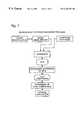
- FIG. 7is a cross-sectional perspective view of a top optics head employed in an embodiment of the invention.
- FIG. 8is a cross-sectional perspective view of an alternative top optics head employed in an embodiment of the invention.
- FIG. 9is a partially schematic cross-sectional view of a chemiluminescence head employed in an embodiment of the invention.
- FIG. 10is a cross-sectional perspective view of a portion of the chemiluminescence head shown in FIG. 8 .
- FIG. 11is a partial perspective view of top and bottom optics heads employed in an embodiment of the invention.
- FIG. 12is a partially schematic side elevation view of the optics assembly shown in FIG. 11, showing an offset between the top and bottom optics head and side illumination.
- FIGS. 13-16are schematic views of sensed volumes in microplate wells.
- FIG. 17is a schematic top view of a microplate.
- FIG. 18is a graph showing the relationships between critical Z-height and microplate well height.
- FIG. 19is a partial perspective, partial schematic view of a light source module employed in an embodiment of the invention.
- FIG. 20is a partial perspective view of an alternative light source module.
- FIG. 21is a partial perspective, partial schematic view of a detector module employed in an embodiment of the invention.
- FIG. 22is a partial perspective view of an alternative light source module.
- FIG. 23is a partial perspective view of a fiber optic shuttle assembly employed in an embodiment of the invention.
- FIG. 24is a perspective view of a floating head assembly employed in the fiber optic shuttle assembly shown in FIG. 23 .
- FIG. 25is a cross-sectional view of the floating head assembly, taken generally along the line 25 — 25 in FIG. 24 .
- FIG. 26is a perspective view of an alternative floating head assembly.
- FIG. 27is a cross-sectional view of the alternative floating head assembly, taken generally along the line 27 — 27 in FIG. 26 .
- FIG. 28is a partially exploded perspective view of an optical filter wheel assembly employed in an embodiment of the invention.
- FIG. 29is a partially exploded perspective view of a portion of an optical filter wheel assembly like that shown in FIG. 28, showing a mechanism by which short filter cartridges may be removed.
- FIG. 30is a partially exploded perspective view of the portion of the optical filter wheel assembly shown in FIG. 29, showing a mechanism by which tall filter cartridges may be removed.
- FIG. 31is a perspective view showing a mechanism by which optical filters may be placed in a tall filter cartridge.
- FIG. 32is a perspective view showing a mechanism by which a friction member may be pressed into place using a funnel and slug.
- FIG. 33is a top view of a short filter cartridge employed in an embodiment of the invention.
- FIG. 34is a cross-sectional view of the short filter cartridge, taken generally along the line 34 — 34 in FIG. 33 .
- FIG. 35is a top view of a tall filter cartridge employed in an embodiment of the invention.
- FIG. 36is a cross-sectional view of the tall filter cartridge, taken generally along the line 36 — 36 in FIG. 35 .
- FIG. 37is a top view of a funnel structure employed in conjunction with an embodiment of the invention.
- FIG. 38is a cross-sectional view of the funnel structure, taken generally along the line 38 — 38 in FIG. 37 .
- FIG. 39is a perspective view of a pivotable filter cartridge employed in an embodiment of the invention.
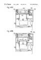
- FIG. 40is a perspective view of the top of a transporter assembly employed in an embodiment of the invention.
- FIG. 41is a perspective view of the bottom of the transporter assembly shown in FIG. 40 .
- FIG. 42is a partial cross-sectional view of the transporter assembly shown in FIGS. 40 and 41, taken generally along the line 42 — 42 in FIG. 41 .
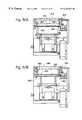
- FIG. 43is a perspective view of a base platform and associated drive mechanisms for moving a transporter along X and Y axes relative to the base platform.
- FIG. 44is a partially exploded perspective view of a housing for an analyzer constructed in accordance with the invention.
- FIG. 45is a front view of the control unit shown in FIG. 44 .
- FIG. 46is a top view of one of the control interface docking locations shown in FIG. 44 .
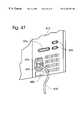
- FIG. 47is a front view of the input/output panel shown in FIG. 44 .
- FIG. 48is a perspective view of a sample feeder constructed in accordance with the invention, with bins removed so that internal mechanisms of the sample feeder can be viewed.
- FIGS. 49A and 49Bare cross-sectional views through a first (input) station of the sample feeder shown in FIG. 48, taken generally along the line 49 AB-— 49 AB in FIG. 48 and showing latch and lifter cooperation to remove a microplate from the bottom of a stack.
- FIGS. 50A and 50Bare cross-sectional views through a third (output) station of the sample feeder shown in FIG. 48, taken generally along the line 50 AB— 50 AB in FIG. 48 and showing latch and lifter cooperation to add a microplate to the bottom of a stack.
- FIG. 51is a side elevation view of a lifter from the sample feeder shown in FIG. 48 .
- the inventionprovides an analyzer capable of supporting a wide range of assay formats that can be carefully selected and fine-tuned for screening desired targets with flexibility, durability, and convenience.
- Flexibilitymeans that the analyzer can be used with a variety of samples and sample assays.
- Durabilitymeans that the analyzer can be used repeatedly, at high throughput, in laboratory and industrial settings.
- Conveniencemeans that the analyzer can be used with only minimal user intervention, while also allowing assays to be run in smaller containers with reduced volumes.
- the analyzerachieves these and other objectives, in part, by employing an optical system that minimizes sample interfacial boundary interference, thereby permitting reduction in assay volume in existing formats such as 96 or 384 well plates, and utilization of denser formats such as 768, 1536, 3456, or 9600 well plates.
- the analyzeralso achieves these objective, in part, by providing the ability automatically to switch between different modes, including absorbance, photoluminescence, photoluminescence polarization, time-resolved photoluminescence, photoluminescence lifetime, and chemiluminescence modalities, among others.
- the apparatus of the present inventiongenerally includes a stage for supporting a composition in an examination site, an automated registration device for bringing successive compositions and the examination site into register for analysis of the compositions, a light source for delivering light into the compositions, a detector for receiving light transmitted from the compositions, and an optical relay structure for transmitting light substantially exclusively from a sensed volume that may comprise only a portion of the composition.
- FIGS. 3-6show a preferred embodiment of the optical system of an analyzer 50 constructed in accordance with the present invention.
- the optical systemgenerally includes at least one light source for delivering light to a composition, at least one detector for receiving light transmitted from the composition, and an optical relay structure for relaying light between the light source, composition, and detector.
- the optical systemmay limit detection to a sensed volume that may comprise only a portion of the composition.
- Components of the optical systemare chosen to optimize sensitivity and dynamic range for each assay mode supported by the analyzer. Toward this end, optical components with low intrinsic luminescence are chosen. In addition, some components are shared by different modes, whereas other components are unique to a particular mode. For example, photoluminescence intensity and steady-state photoluminescence polarization modes share a light source; time-resolved luminescence modes use their own light source; and chemiluminescence modes do not use a light source. Similarly, photoluminescence and chemiluminescence modes use different detectors.
- Luminescenceis the emission of light from excited electronic states of atoms or molecules.
- Luminescencegenerally refers to all kinds of light emission, except incandescence, and may include photoluminescence, chemiluminescence, and electrochemiluminescence, among others.
- photoluminescenceincluding fluorescence and phosphorescence
- the excited electronic stateis created by the absorption of electromagnetic radiation.
- chemiluminescencewhich includes bioluminescence
- electrochemiluminescencethe excited electronic state is created by an electrochemical process.
- the optical system presented hereis a preferred is embodiment.
- the present inventionalso includes other arrangements and components capable of detecting light from a sensed volume in high-throughput applications.
- FIGS. 3-5show the photoluminescence optical system of analyzer 50 .
- the photoluminescence optical systemmust include one or more light sources.
- a continuous source 100provides light for photoluminescence intensity and steady-state photoluminescence polarization assays.
- a preferred continuous sourceis a high-intensity, high-color temperature xenon arc lamp. The preferred source provides more light per unit time than flash sources, increasing sensitivity and reducing read times.
- a time-modulated source 102provides light for time-resolved photoluminescence assays, such as photoluminescence lifetime and time-resolved photoluminescence polarization assays.
- a preferred time-modulated sourceis a xenon flash lamp.
- the preferred sourceproduces a “flash” of light for a brief interval before signal detection and is especially well suited for time-domain measurements.
- Other time-modulated sourcesinclude pulsed lasers, as well as continuous lamps whose intensity can be modulated extrinsically using a Pockels cell, Kerr cell, or other mechanism. The latter sources are especially well suited for frequency- domain measurements.
- Analyzer 50includes light source slots 103 a-d for four light sources, although other numbers of light source slots and light sources also could be provided. The direction of light transmission through the photoluminescence optical system is indicated by arrows.
- light sourcesinclude any sources of electromagnetic radiation of any wavelength capable of inducing photoluminescence or absorption in a composition.
- lightincludes but is not limited to ultraviolet, visible, and infrared radiation.
- Suitable light sourcesinclude lamps, electroluminescence devices, lasers, light-emitting diodes (LEDs), and particle accelerators.
- light produced by such light sourcesmay be 1) mono- or multichromatic, 2) polarized or unpolarized, 3) coherent or incoherent, and/or 4) continuous or time-modulated.
- continuous source 100 and time-modulated source 102produce multichromatic, unpolarized, and incoherent light.
- Continuous source 100produces substantially continuous illumination
- time-modulated source 102produces time-modulated illumination.
- Light from these light sourcesmay be delivered to the sample without modification, or it may be filtered to alter its intensity, spectrum polarization, or other properties.
- Light produced by the light sourcesfollows an excitation optical path to an examination site. Such light may pass through one or more “spectral filters,” which generally comprise any mechanism for altering the spectrum of light that is delivered to the sample. Spectrum refers to the wavelength composition of light. A spectral filter may be used to convert white or multichromatic light, which includes light of many colors, into red, blue, green, or other substantially monochromatic light, which includes light of one or only a few colors.
- spectrumis altered by an excitation interference filter 104 , which selectively transmits light of preselected wavelengths and selectively absorbs light of other wavelengths.
- excitation interference filters 104may be housed in an excitation filter wheel 106 , which allows the spectrum of excitation light to be changed by rotating a preselected filter into the optical path.
- Spectral filtersalso may separate light spatially by wavelength. Examples include gratings, monochromators, and prisms.
- excitation filter wheel 106may be mounted in the optical path of some light source slots 103 a,b but not other light source slots 103 c,d.
- the optics headsinclude various optics for delivering light into the sensed volume and for receiving light transmitted from the sensed volume.
- Lightis transmitted through a fiber optic cable much like water is transmitted through a garden hose.
- Fiber optic cablescan be used easily to turn light around comers and to route light around opaque components of the analyzer. Moreover, fiber optic cables give the light a more uniform intensity profile.
- a preferred fiber optic cableis a fused silicon bundle, which has low autofluorescence. Despite these advantages, light also can be delivered to the optics heads using other mechanisms, such as mirrors.
- Excitation polarization filtersmay be included with the top and/or bottom optics head.
- Excitation polarization filters 114may include an s-polarizer S that passes only s-polarized light, a p-polarizer P that passes only p-polarized light, and a blank O that passes substantially all light.
- Excitation polarizers 114also may include a standard or ferro-electric liquid crystal display (LCD) polarization switching system. Such a system is faster and more economical than a mechanical switcher. Excitation polarizers 114 also may include a continuous mode LCD polarization rotator with synchronous detection to increase the signal-to-noise ratio in polarization assays.
- LCDliquid crystal display
- the confocal optics elementgenerally comprises any mechanism for focusing light into a “sensed volume.”
- the confocal optics elementincludes a set of lenses 117 a-c and an excitation aperture 116 placed in an image plane conjugate to the sensed volume, as shown in FIG. 5 .
- Lenses 117 a,bproject an image of this aperture onto the sample, so that only a preselected or sensed volume of the sample is illuminated.
- Light traveling through the optics headsis reflected and transmitted through a beamsplitter 118 , which delivers reflected light to a composition 120 and transmitted light to a light monitor 122 .
- Reflected and transmitted lightboth pass through lens 117 b , which is operatively positioned between beamsplitter 118 and composition 120 .
- the beamsplitteris changeable, so that it may be optimized for different assay modes or compositions.
- the light monitoris used to correct for fluctuations in the intensity of light provided by the light sources; such corrections are performed by reporting detected intensities as a ratio over corresponding times of the luminescence intensity measured by the detector to the excitation light intensity measured by the light monitor.
- the light monitoralso can be programmed to alert the user if the light source fails.
- a preferred light monitoris a silicon photodiode with a quartz window for low autofluorescence.
- the composition(or sample) is held in a sample container supported by a stage 123 .
- the compositioncan include compounds, mixtures, surfaces, solutions, emulsions, suspensions, cell cultures, fermentation cultures, cells, tissues, secretions, and/or derivatives and/or extracts thereof. Analysis of the compositions may involve measuring the presence, concentration, or physical properties of a photoluminescent analyte in such a composition.
- the sample containercan include microplates, gene chips, or any array of samples in a known format.
- the preferred sample containeris a microplate 124 , which includes a plurality of microplate wells 126 for holding compositions.
- Compositionmay refer to the contents of a single microplate well, or several microplate wells, depending on the assay.
- the position of the sensed volume within the composition created by the confocal optics elementcan be moved precisely to optimize the signal-to-noise and signal-to-background ratios.
- position in the X,Y-plane perpendicular to the optical pathis controlled by moving the stage supporting the composition, whereas position along the Z-axis parallel to the optical path is controlled by moving the optics heads using a Z-axis adjustment mechanism 130 , as shown in FIGS. 3 and 4.
- any mechanism for bringing the sensed volume into register or alignment with the appropriate portion of the compositionalso may be employed.
- top and bottom opticspermits assays to combine: (1) top illumination and top detection, or (2) top illumination and bottom detection, or (3) bottom illumination and top detection, or (4) bottom illumination and bottom detection.
- Same-side illumination and detection (1) and (4)is referred to as “epi” and is preferred for photoluminescence assays.
- Opposite-side illumination and detection (2) and (3)is referred to as “trans” and is preferred for absorbance assays.
- epi modesare supported, so the excitation and emission light travel the same path in the optics head.
- trans modesalso could be supported and would be essential for absorbance assays.
- top opticscan be used with any sample container having an A open top
- bottom opticscan be used only with sample containers having optically transparent bottoms, such as glass or thin plastic bottoms.
- Lightis transmitted by the composition in multiple directions. A portion of the transmitted light will follow an emission pathway to a detector. Transmitted light passes through lens 117 c and may pass through an emission aperture 131 and/or an emission polarizer 132 .
- the emission apertureis placed in an image plane conjugate to the sensed volume and transmits light substantially exclusively from this sensed volume.
- the emission apertures in the top and bottom optical systemsare the same size as the associated excitation apertures, although other sizes also may be used.
- the emission polarizersare included only with top optics head 112 a. The emission aperture and emission polarizer are substantially similar to their excitation counterparts.
- Excitation polarizers 114 and emission polarizers 132may be used together in nonpolarization assays to reject certain background signals.
- Luminescence from the sample container and from luminescent molecules adhered to the sample containeris expected to be polarized, because the rotational mobility of these molecules should be hindered.
- Such polarized background signalscan be eliminated by “crossing” the excitation and emission polarizers, that is, setting the angle between their transmission axes at 90°.
- beamsplitter 118should be optimized for reflection of one polarization and transmission of the other polarization. This method will work best where the luminescent molecules of interest emit relatively unpolarized light, as will be true for small luminescent molecules in solution.
- Transmitted lightnext passes through an emission fiber optic cable 134 a,b to an emission optical shuttle (or switch) 136 .
- This shuttlepositions the appropriate emission fiber optic cable in front of the appropriate detector.
- these componentsare substantially similar to their excitation counterparts, although other mechanisms also could be employed.
- Light exiting the fiber optic cablenext may pass through one or more emission “intensity filters,” which generally comprise any mechanism for reducing the intensity of light. Intensity refers to the amount of light per unit area per unit time.
- intensityis altered by emission neutral density filters 138 , which absorb light substantially independent of its wavelength, dissipating the absorbed energy as heat.
- Emission neutral density filters 138may include a high-density filter H that absorbs most incident light, a medium-density filter M that absorbs somewhat less incident light, and a blank O that absorbs substantially no incident light. These filters are changed by hand, although other methods also could be employed, such as a filter wheel.
- Intensity filtersalso may divert a portion of the light away from the sample without absorption. Examples include beam splitters, which transmit some light along one path and reflect other light along another path, and Pockels cells, which deflect light along different paths through diffraction.
- Emission interference filter 140may be housed in an emission filter wheel 142 .
- these componentsare substantially similar to their excitation counterparts, although other mechanisms also could be employed.
- Emission interference filtersblock stray excitation light, which may enter the emission path through various mechanisms, including reflection and scattering. If unblocked, such stray excitation light could be detected and misidentified as photoluminescence, decreasing the signal-to-background ratio.
- Emission interference filterscan separate photoluminescence from excitation light because photoluminescence has longer wavelengths than the associated excitation light.
- filters used here in only one optical pathsuch as intensity filters
- filters used here in only top or bottom opticssuch as polarization filters
- filters used here in only top or bottom opticssuch as polarization filters
- the optimal positions and combinations of filters for a particular experimentwill depend on the assay mode and the composition, among other factors.
- Analyzer 50includes detector slots 145 a-d for four detectors, although other numbers of detector slots and detectors also could be provided.
- detectorscomprise any mechanism capable of converting energy from detected light into signals that may be processed by the analyzer. Suitable detectors include photomultiplier tubes, photodiodes, avalanche photodiodes, charge-coupled devices (CCDs), and intensified CCDs, among others. Depending on the detector and assay mode, such detectors may be used in (1) photon-counting or continuous modes, and (2) imaging or integrating modes.
- FIGS. 3, 4 , and 6show the chemiluminescence optical system of analyzer 50 . Because chemiluminescence follows a chemical event rather than the absorption of light, the chemiluminescence optical system does not require a light source or other excitation optical components. Instead, the chemiluminescence optical system requires only selected emission optical components. In analyzer 50 , a separate lensless chemiluminescence optical system is employed, which is optimized for maximum sensitivity in the detection of chemiluminescence.
- chemiluminescence optical systemperforms the same functions and are subject to the same caveats and alternatives as their counterparts in the photoluminescence optical system.
- the chemiluminescence optical systemalso can be used for other assay modes that do not require illumination, such as electrochemiluminescence.
- the chemiluminescence optical pathbegins with a chemiluminescent composition 120 held in a sample container 126 .
- the composition and sample containerare analogous to those used in photoluminescence assays; however, analysis of the composition involves measuring the intensity of light generated by a chemiluminescence reaction within the composition rather than by light-induced photoluminescence.
- a familiar example of chemiluminescenceis the glow of the firefly.
- Chemiluminescence lighttypically is transmitted from the composition in all directions, although most will be absorbed or reflected by the walls of the sample container. A portion of the light transmitted through the top of the well is collected using a chemiluminescence head 150 , as shown in FIG. 3, and will follow a chemiluminescence optical pathway to a detector. The direction of light transmission through the chemiluminescence optical system is indicated by arrows.
- the chemiluminescence headincludes a nonconfocal mechanism for transmitting light from a sensed volume within the composition. Detecting from a sensed volume reduces contributions to the chemiluminescence signal resulting from “cross talk,” which is pickup from neighboring wells.
- the nonconfocal mechanismincludes a chemiluminescence baffle 152 , which includes rugosities 153 that absorb or reflect light from other wells.
- the nonconfocal mechanismalso includes a chemiluminescence aperture 154 that further confines detection to a sensed volume.
- Fiber optic cable 156may include a transparent, open-ended lumen that may be filled with fluid. This lumen would allow the fiber optic to be used both to transmit luminescence from a microplate well and to dispense fluids into the microplate well. The effect of such a lumen on the optical properties of the fiber optic could be minimized by employing transparent fluids having optical indices matched to the optical index of the fiber optic.
- chemiluminescence intensity filterswhich generally comprise any mechanism for reducing the intensity of light.
- intensityis altered by chemiluminescence neutral density filters 158 .
- Lightalso may Mi pass through other filters, if desired.
- chemiluminescence detector 160there is one chemiluminescence detector 160 .
- This detectormay be selected to optimize detection of blue/green light, which is the type most often produced in chemiluminescence.
- a preferred detectoris a photomultiplier tube, selected for high quantum efficiency and low dark count at chemiluminescence wavelengths (400-500 nanometers).
- FIG. 7shows a cross-sectional view of top optics head 112 a , which is used together with fiber optic cables 110 a , 134 a and apertures 116 , 131 , as shown in FIG. 5, to create the sensed volume.
- Top optics head 112 ais substantially similar to bottom optics head 112 b, as shown in FIGS. 11 and 12, except that top optics head 112 a includes chemiluminescence head 150 and excitation and emission polarizers 114 , 132 (not shown), and that bottom optics head 112 b includes a window and drip lip (described below).
- Excitation lightarrives at top optics head 112 a through excitation fiber optic cable 110 a.
- Fiber optic cablesare cylindrical waveguides that transmit light through a process known as total internal reflection.
- Fiber optic cablesare characterized by a numerical aperture, which describes the maximum angle through which the fiber optic cable can collect light for total internal reflection. The higher the numerical aperture, the greater the angle over which the fiber optic cable can collect and transmit light.
- the medium adjacent the fiber optic cableis air, so n ⁇ 1.
- exiting excitation lightforms a first cone 170 of excitation light, with its apex positioned just inside the tip 172 of fiber optic cable 110 a .
- First cone 170 of excitation lightpasses through an excitation polarizer 114 (not shown), and then through a first plano-convex converging lens 174 , whose plan side 176 is oriented toward fiber optic cable 110 a.
- First lens 174is positioned so that it substantially converts first cone 170 of excitation light into a first cylinder 178 of excitation light. This conversion is accomplished by positioning tip 172 substantially at the focal point of first lens 174 .
- First cylinder 178 of excitation lightimpinges on beamsplitter 118 a .
- Beamsplitter 118 areflects a reflected cylinder portion 180 of excitation light toward composition 120 in sample well 126 .
- Reflected cylinder portion 180passes through a second plano-convex converging lens 182 , whose plan side 184 is oriented away from beamsplitter 118 a.
- Second lens 182converts reflected cylinder portion 180 of excitation light into a second cone 186 of excitation light, which is focused onto and thus delivered to composition 120 in sample well 126 .
- the cone angle ⁇ 2 of second cone 186is determined in part by the numerical aperture of second lens 182 , and may be different from the cone angle ⁇ 1 describing excitation light exiting fiber optic cable 110 a.
- Beamsplitter 118 aalso transmits a transmitted cylinder portion 188 of the excitation light to light monitor 122 , which functions as described above.
- the optics used to focus the transmitted light into the light monitormay be substantially similar to the optics used to focus the reflected light into the sample well.
- the opticsmay include a lensless system, such as a black tapered cone to direct light.
- the excitation lightmay induce photoluminescence within the composition.
- Photoluminescence (or emission) lighthas longer wavelengths than the associated excitation light. This is due to conservation of energy; in photoluminescence, the emission light has lower energy (and so longer wavelength) than the excitation light, because some of the energy of the excitation light is lost nonradiatively.
- a conical portion of the emission light substantially coextensive with second cone 186 of excitation lightpasses back through second lens 182 , which converts the conical portion into a cylindrical portion of emission light substantially coextensive with reflected cylinder 180 of excitation light.
- Emission lightnext impinges on beamsplitter 118 a , which transmits a cylinder portion 190 of emission light toward photoluminescence detector 144 .
- Beamsplitter 118 atypically is chosen to accommodate one of two different scenarios. If a large number or variety of luminescent molecules are to be studied, the beamsplitter must be able to accommodate light of many wavelengths; in this case, a “50:50” beamsplitter that reflects half and transmits half of the incident light independent of wavelength is optimal. Such a beamsplitter can be used with many types of molecules, while still delivering considerable excitation light onto the composition, and while still transmitting considerable emission light to the detector.
- the beamsplitterneeds only to be able to accommodate light at a limited number of wavelengths; in this case, a “dichroic” or “multichroic” beamsplitter is optimal.
- a “dichroic” or “multichroic” beamsplitteris optimal.
- Such a beamsplittercan be designed for the appropriate set of molecules and will reflect most or substantially all of the excitation light, while transmitting most or substantially all of the emission light. This is possible because the reflectivity and transmissivity of the beamsplitter can be varied with wavelength.
- Cylinder portion 190 of emission light transmitted through beamsplitter 118 apasses through a third plano-convex converging lens 192 , whose plan side 194 is oriented away from the beamsplitter.
- emission lightfirst may pass through an emission polarizer 132 , as shown in FIG. 5 .
- Third lens 192focuses the cylindrical portion 190 of emission light into a third cone of light 196 that impinges on emission fiber optic cable 134 a for transmission to photoluminescence detector 144 .
- the lightshould be focused onto emission aperture 131 at the tip 198 of the fiber as a spot comparable in size to the diameter of the fiber optic cable.
- the incident cone angle ⁇ 3should not exceed the inverse sine of the numerical aperture of the fiber.
- a property of the optical arrangement in top optics head 112 ais that the tips 172 , 198 of fiber optic cables 110 a , 134 a and the sensed volume of the composition are “confocal.” Confocal means that all three objects are in conjugate focal planes, so that whenever one is in focus, all are in focus.
- the sensed volume of the compositionlies in a focal or sample plane FP of the system, and the tips of the fiber optic cables lie in image planes IP of the system.
- the detectoralso may be placed in an image plane, so that it detects the composition in focus.
- the tips of the fiber optic cablesmay be said to lie in intermediate image planes, because light passes through these planes, and the detector may be said to lie in a terminal image plane, because light terminates on the detector.
- the sensed volumeis created by placing confocal optics elements in or near one or more intermediate image planes.
- a preferred confocal optics elementis an aperture. If such an aperture is placed in the excitation optical path, an image of the aperture will be focused onto the composition. As a result, only a portion of the composition within the focal plane corresponding to the shape and proportional to the size of the aperture will be illuminated, and only luminescent molecules in or near that en portion of the focal plane will be induced to emit photoluminescence. If such an aperture is placed in the emission optical path, an image of the aperture will be focused onto the detector. Luminescence that ordinarily would focus onto a part of the detector outside the image of the aperture will be blocked or masked from reaching the detector.
- the “shape” (or intensity profile) of the sensed volumedepends on the confocal optics elements, such as excitation and emission apertures 116 , 131 , the light source, and the numerical apertures of the lenses and fiber optic cables. Generally, the intensity of the light incident on (or emitted from) the sensed volume will be greatest at the center of the sensed volume, and will decay monotonically in all directions away from the center. Most of the intensity will lie within a distance equal to about one aperture diameter from the center of the sensed volume in the Z direction, and within about one-half an aperture diameter from the center of the sensed volume in the X and Y directions.
- FIG. 7also shows a sample container sensor switch 230 , which is used to prevent damage to optics head 112 a by preventing the optics head from physically contacting a sample container.
- Sample container sensor switch 230is mounted about a pivot axis P adjacent chemiluminescence head 150 .
- Sample container sensor switch 230includes a sensor surface 232 positioned so that a sample container must contact the sensor surface before contacting any component of top optics head 112 a .
- Contact between a sample container and sensor surface 232causes sample container sensor switch 230 to pivot about pivot axis P, activating an electrical circuit that turns off power to the mechanism(s) used to move the sample container.
- a sample container sensor switchis especially important in an analyzer designed for use with a variety of sample containers, because it reduces the likelihood of damage both from exotic sample holders with unusual dimensions and from standard sample holders with aberrant or misidentified dimensions.
- the sample container sensor switchmay detect impending contact between the sample container and optics head (1) mechanically, as in the preferred embodiment, (2) optically, as with an electric eye, (3) acoustically, as with an ultrasonic detector, or (4) by other mechanisms.
- the sample container sensor switchmay include a linear voltage displacement transducer (LVDT), which measures displacement by creating a voltage proportional to the displacement.
- LVDTlinear voltage displacement transducer
- FIG. 7also shows a chemiluminescence head 150 , which includes a chemiluminescence baffle 152 and a chemiluminescence fiber optic cable 156 .
- Chemiluminescence head 150is mounted on top optics head 1121 but also could be mounted on bottom optics head 112 b or on both top and bottom optics heads 112 a,b.
- FIG. 8shows an alternative embodiment of top optics head 112 a which includes an alternative embodiment of chemiluminescence head 150 .
- FIG. 9shows an alternative view of chemiluminescence head 150 .
- emission light sensitivityis maximized by detecting as much emission light as possible from the top of the sample container.
- analyzer 50this is accomplished by placing fiber optic cable 156 directly above and aligned with the center of the microplate well or other sample container.
- a high numerical aperture fiber optic cablemay be used to collect most or substantially all of the light emitted from the composition.
- a preferred fiber optic cablehas a numerical aperture of 0.22 and is formed of silica for low autoluminescence.
- Detection of chemiluminescence lightfurther is enhanced by positioning fiber optic cable 156 so that the gap G or flying height between the fiber optic cable and the top of the sample container is as small as possible. Generally, if the gap between the top of the microplate and the fiber optic cable is small compared to the diameter of the fiber optic cable, most of the emission light will be collected.
- preferred values of Glie in the range 0.25-1.5 mm, depending on the type of microplate. The preferred values allow for normal variations in microplate thickness and minimize the possibility of contacting liquid that may be on the surface of the microplate. This is accomplished by accurate calibration of the travel of the optical head along the Z-axis relative to a reference point on the Z-axis.
- the height of various microplatescan be stored in software so that G can be set by the instrument to a preselected value.
- Gap Galso can be determined empirically using a precision top-of-plate sensor, which is mounted on the bottom of the upper optics head.
- the height of the plateis measured by slowly moving the optics head toward the plate until the top-of-plate sensor indicates that a known flying height has been achieved. With this approach, the height of the plate need not be known in advance. Moreover, if a microplate mistakenly is inserted into the machine with a greater than expected height, the top-of-plate sensor can be used to prevent the optics head from colliding with the microplate.
- Chemiluminescence head 150also includes a chemiluminescence baffle 152 , which supports fiber optic cable 156 and an aperture support slide 250 and which also minimizes detection of ambient light and chemiluminescence from neighboring wells. Detection from neighboring wells may be referred to as “cross talk.”
- chemiluminescence baffle 152is generally circular and includes a black surface 252 with rugosities 153 designed to absorb light.
- Chemiluminescence baffle 152may have a diameter at least about twice the diameter of the fiber optic cable, and may be configured to allow low cross talk to be achieved at comfortable flying heights.
- FIG. 10shows a partially cross-sectional perspective view of chemiluminescence head 150 .
- Chemiluminescence head 150includes a fiber optic cable 156 and an aperture support plate 250 containing apertures 254 a,b that determine an “effective” entrance diameter for the fiber optic cable.
- the effective entrance diameter for the fiber optic cabledetermines the size of the sensed volume within the sample.
- apertures 254 a,bgenerally are chosen substantially to equal the diameter of the microplate well. Large apertures 254 a having diameters larger than fiber optic cable 156 , and small apertures 254 b having diameters smaller than fiber optic cable 156 may be placed in front of the fiber optic cable.
- a moveable aperture support slide 250may include separate apertures for 96, 384, 768, 1536, 3456, and 9600 well plates, among others, where each aperture is optimized for the well size associated with a particular microplate.
- a fixed aperture support slide 250may include a continuous iris diaphragm aperture, where the size of the continuous diaphragm may be optimized for a range of well sizes.
- chemiluminescence optical systemcould include a plurality of chemiluminescence heads optically connected to a plurality of chemiluminescence detectors.
- the chemiluminescence headscould be mounted as a linear array or as a matrix.
- a linear array of 8 or 12 chemiluminescence heads optically connected to 8 or 12 detectorscould be used to detect simultaneously from entire rows or columns of a 96-well microplate.
- the same arraysalso could be used with the appropriate apertures to detect from higher-density plates in which the well-to-well spacing is evenly divisible into the well-to-well spacing in the 96-well plate, as for 384 and 1536-well plates.
- the chemiluminescence headsalso could be mounted as a matrix that could detect from one or more plate formats.
- chemiluminescence optical systemcould include a plurality of fiber optic cables connected as a bundle to a CCD detector or to a PMT array.
- the fiber optic bundlecould be constructed of discrete fibers or of many small fibers fused together to form a solid bundle. Such solid bundles are commercially available and easily interfaced to CCD detectors.
- chemiluminescence baffle 152may be used with alternative embodiments of chemiluminescence baffle 152 .
- cross-talk between wells within the matrixcan be minimized by keeping G as small as possible and/or by applying an anti-reflective coating to the face of the fiber bundle.
- An anti-reflective coatingcan reduce reflected light from about 4% to less than 1%.
- a baffle having a rough black surface as described abovecould be placed around the outside of the fiber bundle, like a collar, to minimize pick-up from areas of the plate that are not under the bundle.
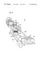
- FIG. 11shows the relationship between top and bottom optics heads 112 a,b, and chemiluminescence head 150 .
- Top and bottom optics heads 112 a,bare coupled to an optics head support structure 260 , which includes a gap 262 through which a stage and sample container can pass.
- Optics head support structure 260is configured so that the relative positions of top and bottom optics heads 112 a,b are fixed.
- FIG. 11also shows a Z-axis adjustment mechanism 130 , which is used to adjust the position of a sensed volume within a composition.
- Z-axis adjustment mechanism 130includes a support track 264 that is substantially parallel to a Z-axis on which optics head support structure 260 is mounted.
- Z-axis adjustment mechanism 130also includes a motor 266 for moving optics head support structure 260 along support track 264 .
- the position of a sensed volume within a composition positioned in gap 262is adjusted by moving top and bottom optics heads 112 a,b relative to the composition. Movement relative to the composition may be effected by moving the optics heads while keeping the composition stationary, as here, or by moving the composition while keeping the optics heads stationary, among other mechanisms.
- FIG. 11also shows aspects of bottom optics head 112 b.
- bottom optics head 112 bresembles top optics head 112 a.
- bottom optics head 112 bincludes a window 267 and an elevated drip lip 268 that are not included on top optics head 112 a. Window 267 and drip lip 268 prevent fluid dripped from a microplate from entering bottom optics head 112 b. Fluid dripped from a microplate is a concern with bottom optics head 112 b because the bottom optics head is positioned below the microplate during analysis.
- FIGS. 11 and 12show further aspects of bottom optics head 112 b .
- lightis directed through bottom optics head 112 b much like light is directed through top optics head 112 a.
- lightalso may be directed by an alternative optical relay structure 269 to the bottom (or top) optics head.
- Alternative optical relay structure 269may include a fiber optic cable 270 and focusing lens structure 271 .
- Off-axis illuminationeliminates loss of light due to absorption and reflection from the beam splitter and substantially eliminates reflection of incident light into the detection optics, reducing background. Off-axis illumination also may be used for total internal reflection illumination.
- FIGS. 11 and 12also show the relative positions of top and bottom optics heads 112 a,b .
- Top and bottom optics heads 112 a,bmay be aligned, so that excitation light transmitted by one optics head can be detected by the other optics head, facilitating absorbance assays.
- a shuttermay be positioned between the two optics heads to prevent light from one optics head from entering and exciting fluorescence from the other optics head during luminescence assays.
- top and bottom optics head 112 a,bmay be offset, so that light from one optics head cannot enter the other optics head.
- a small A optical relay structuresuch as a fiber optic cable, may be positioned adjacent or as part of bottom optics head 112 b to detect light in a top illumination and bottom detection mode.
- optical system described aboveand the confocal optics elements in particular, allow detection of luminescence substantially exclusively from a sensed volume of a composition.
- FIG. 13shows a standard microplate well 126 and an excitation light beam 186 as it illuminates the well.
- the standard wellis cylindrical and may be characterized by a diameter D w and a height H w .
- Other wellsmay have other geometries and be characterized by other quantities; for example, a well could be square and characterized by a width and a height, or a well could be conical and characterized by a cone angle and a height.
- the interface between composition 120 and the air 272is termed the meniscus 274 and may be convex, plan, or concave.
- Excitation light beam 186is focused by the optical system so that it is shaped much like an hourglass along the optical (Z) axis. This hourglass shape arises as the cone of excitation light formed by the optics passes through focus.
- the diameter D B of the beamis smallest at the beam's waist 276 , which corresponds to the focal plane, above and below which the beam diverges monotonically, making an angle ⁇ B with respect to the vertical or Z-axis.
- Values of D B and ⁇ Bdepend on optical components of the analyzer and may be varied by changing these components. Generally, D B and ⁇ B are inversely related.
- the distance between the bottom of the well and the beam waistis termed the focal (Z) height, H z .
- the shape of the sensed volumemay differ in directions parallel and perpendicular to the optical or Z-axis. Parallel to the Z-axis, the shape may be Lorentzian, among others. Perpendicular to the Z-axis, the shape may be Gaussian, or it may be a rounded pulse function, among others. A laser beam might give rise to a Gaussian, whereas a fiber optic bundle might give rise to a rounded pulse function. Generally, lower numerical apertures will create sensed volumes shaped more like cylinders, whereas higher numerical apertures will create sensed volumes shaped more like hourglasses.
- the shape and volume of the sensed volumemay be adapted like a probe to match the shape and volume of the sample container.
- the sensed volumemay be expanded for maximum signal in a large sample container, and contracted to avoid nearby walls in a small sample container.
- the shape and volume of the sample containeralso may be chosen or designed to conform to the shape and volume of the sensed volume.
- the sensed volumemay be held constant. In this way, the sensed volume will report on equal volumes of each composition analyzed, so that the analyzer effectively reports “intensive” quantities. Intensive quantities do not depend on the amount of composition in a sample container; in contrast, extensive quantities do depend on the amount of composition in the sample container.
- This approachcan be used to facilitate comparison of results obtained from different-sized sample wells, such as in 96 and 384 well microplates. Alternatively, this approach can be used to facilitate comparison of results obtained from like-sized sample wells containing different volumes of solution, as by design or by error.
- FIG. 14shows how the signal-to-noise and signal-to-background ratios are affected by focal height for two assay modes.
- photoluminescent moleculesare distributed uniformly throughout the composition, and the optimum signal-to-noise and signal-to-background ratios are obtained regardless of well geometry when the sensed volume is positioned in the middle of the composition (Panel A), so that the sensed volume does not overlap with the meniscus or the bottom or sides of the well. If the meniscus is in the sensed volume, light reflected from the meniscus will be detected. This will decrease sensitivity by increasing background and decreasing signal. If the bottom of the well is in the sensed volume, light reflected from the well bottom will be detected.
- the shape and position of the sensed volume within the wellare affected by (1) the meniscus, (2) the geometry of the microplate well, and (3) the geometry of the whole microplate.
- FIG. 15shows how the meniscus affects the shape and position of the sensed volume.
- the beamhas a nominal undistorted shape; see Panel A.
- the meniscusaffects the sensed volume because light is refracted as it crosses the meniscus boundary between the air and the composition. Specifically, light passing from air (with its lower index of refraction) to the composition (with its higher index of refraction) bends toward the normal, as described by Snell's law.
- the normalis the direction perpendicular to the surface of the meniscus at a given point. If the meniscus is everywhere perpendicular to the light beam, then light passing through the meniscus will not bend, and the beam will retain its nominal undistorted shape.
- FIGS. 16 and 17show how the geometry of the microplate well affects the position of the sensed volume.
- the wellis sufficiently narrow relative to the diameter of the beam or if the well is sufficiently deep relative to the angle made by the beam, then the light beam may impinge upon the top walls of the well.
- setting the Z-height too lowcan reduce sensitivity (1) by decreasing the desired signal because less light enters the well, and (2) by increasing the background because the light beam illuminates the tops of wells.
- Many microplatesare made from materials that are fluorescent or otherwise photoluminescent, and the instrument will detect this photoluminescence from materials at the tops of wells.
- FIG. 17shows how the geometry of the microplate affects the position of the sensed volume.
- the analyzeris configured automatically to find the location of each well in a given microplate, beginning with well A 1 .
- the analyzerdoes this using stored parameters describing the dimensions (plate heights, interwell distances, etc.) of the particular microplate style.
- these microplate parametersare nominal values and do not account for unit-to-unit or lot-to-lot variations in microplate geometry. If there is a slight variation in interwell distance, the light beam can be off-center on some wells even though it is perfectly centered on well A 1 . This effect is termed cross-plate drift.
- Cross-plate drift of fluorescence readingsmay increase as the instrument scans across the microplate as variations are compounded. Typically, drift will be worst at well H 12 , which is farthest from well A1. Such drift can be reduced by making the stage more accurate, by making the sample containers of a more consistent size, or by increasing H z , which will reduce the diameter of the beam and put it back into the well. The lattermost approach is shown for well G 11 .
- FIG. 18shows how H Z,Crit depends on the well height H W and well diameter D W , for a beam of diameter 1.5 millimeters (mm) and a beam angle ⁇ B of 12.7 degrees.
- Table 1shows how H Z,Crit depends on well height and well diameter for four commercially available microplates.
- Z-heightcan be optimized for a particular microplate and chemistry by (1) preparing a test microplate with representative chemistry (e.g., blanks, positive and negative controls, dilution series), (2) and reading the microplate multiple times at different Z-heights to determine the Z-height that gives the best signal-to-background data.
- Representative chemistrye.g., blanks, positive and negative controls, dilution series
- Some combinations of chemistry and microplateare relatively insensitive to Z-height, while others demonstrate a distinct optimum.
- a sample container sensor switchis mounted on the top optics head to prevent the plate from contacting the optics head in case the plate is misaligned, not properly specified, or the Z-height is set incorrectly. If this sensor detects a fault, the sample container will be ejected prior to reading.
- FIG. 19is a perspective view of a light source module 400 employed in an embodiment of the invention. Portions of the module case have been removed to reveal internal componentry.
- Light source module 400includes at least two light sources.
- a flash lamp 402transmits light along a first light path 404 .
- a second light sourcenamely, a continuous arc lamp (not shown) housed in compartment 406 , transmits light along a second light path 408 .
- a filter wheel assembly 410is positioned adjacent the light sources.
- Filter wheel assembly 410includes a filter wheel 412 , which holds a plurality of filters 414 .
- Filter wheel 412is rotatable around an axis 416 , so that a given filter can be positioned interchangeably along light path 404 , or along light path 408 , by rotating filter wheel 412 .
- a fiber optic shuttle assembly 418is mounted next to filter wheel assembly 410 .
- Moveable shuttle 420translates along support tracks 422 a and 422 b , so that moveable shuttle 420 can be positioned in front of a selected light source for a selected assay application.
- Two fiber optic ports 424are provided on an external face of shuttle 420 . Fiber optic ports 424 direct light, via fiber optic cables, from a selected source either to a top optics head or to a bottom optics head, above and below a stage holding a sample, respectively.
- FIG. 20is a perspective view of an alternative light source module 426 .
- filter wheel assembly 410 of light source module 400has been replaced by an alternative filter wheel assembly 427 .
- a moveable shuttle 428is shown in an alternative position relative to moveable shuttle 420 in light source module 400 .
- FIG. 21is a perspective view of a detector module 440 employed in an embodiment of the invention. Portions of the module case have been removed to reveal internal componentry.
- Detector module 440is similar to light source module 400 .
- a detector 442receives light directed along a light path 444 , originating from a sample.
- a filter wheel assembly 446is positioned in front of detector 442 .
- Filter wheel assembly 446includes a plurality of filters 450 and is rotatable around an axis 451 by a stepper, DC servo, or other motor. The filter wheel can be rotated at a preselected angular speed to allow synchronization with a flash lamp light source and a detector.
- a port 452 for a second detectoris provided in filter wheel assembly 446 , so that a second detector can be mounted in detector module 440 .
- a given filter in filter wheel 448can be positioned along a first light path 444 leading to detector 442 , or alternatively can be positioned along a second light path leading to a second detector (not shown).
- An attenuator mechanism 454is mounted adjacent filter wheel assembly 446 .
- a fiber optic shuttle assembly 456is mounted in front of attenuator mechanism 454 .
- Shuttle assembly 456includes a moveable shuttle 458 , which is moveable along upper and lower support tracks 460 a and 460 b, respectively.
- An exterior face of shuttle 458has two fiber optic ports 462 , one of which is connected, via a fiber optic cable, to a top optics head above the examination site, the other of which is connected, via a fiber optic cable, to a bottom optics head below the examination site.
- moveable shuttle 458can be moved along support tracks 460 a and 460 b to connect optically either one of the optics heads to any one of the detectors (if more than one is included in the module), and through any one of filters 450 in filter wheel 448 .
- FIG. 22is a perspective view of an alternative detector module 466 .
- filter wheel assembly 446 of detector module 440has been replaced by an alternative filter wheel assembly 467 .
- a moveable shuttle 468is shown in an alternative position relative to moveable shuttle 458 in detector module 440 .
- Light source and detector modulesare designed for flexibility. Additional ports for fiber optics or other optical relay structures may be provided, if desired. The number and configuration of such other ports may be tied to the number and configuration of light-transmission routes through the filter wheel. Optical components also may be connected directly to the moveable shuttle. Such a connection would be especially useful for small, dedicated components, such as a beamsplitter and photodiode-type detector that could sample a portion of the light transmitted through the port to correct for output fluctuations from a light source.
- FIGS. 19 and 21, and FIGS. 20 and 22show that many aspects of light source modules 400 and 426 and detector modules 440 and 466 are the same, particularly the mechanics of filter wheel assemblies 410 and 446 , filter wheel assemblies 427 and 467 , and fiber optic shuttle assemblies 418 and 456 .
- the light source and detector modulesboth function as registration mechanisms that align the end of an optical relay structure with an aperture in a surface. This surface may enclose a light source, detector, or other optical component.
- the light source and detector modulesboth permit alignment with two such apertures, and with portions of a surface not including an aperture to prevent the optical relay structure from transmitting light.
- Light source and detector modulesalso may be configured to transmit light directly from module to module, using air, a tube, or other mechanism to transmit light. If used together in a light detection device, the light source and detector modules provide a great deal of analytical flexibility to select different combinations of light sources, detectors, and filters for different applications, while also being able to select different combinations of top versus bottom illumination and detection orientation
- FIG. 23is a partial perspective view of a fiber optic shuttle assembly 480 like those used in light source module 400 and detector module 440 .
- Fiber optic shuttle assembly 480includes a moveable shuttle 481 and two floating head assemblies 482 .
- each floating head assembly 482may be used to create and maintain a light-tight connection between selected light sources or detectors and fiber optic cables, such as those that lead to an examination site, or to a top optics head or a bottom op tics head, above and be low a stage, respectively.
- FIG. 24shows a perspective view of a floating head assembly 483 employed in an embodiment of the invention.
- floating head assembly 483includes a fiber optic ferule 484 having an end 485 configured to transmit light, and an opaque collar 486 positioned around the end.
- Fiber optic ferule 484is used to transmit light.
- Fiber optic ferule 484may be replaced by a portion of a light source, detector, or other optical component.
- Opaque collar 486is used to block light and preferably comprises a hard plastic material.
- Opaque collar 486encompasses and extends beyond end 485 .
- An opaque base structure 487contains additional elements. Together, opaque collar 486 and base structure 487 form a pair of concentric, partially overlapping walls positioned around fiber optic ferule 484 .
- FIG. 25is a cross-sectional view of floating head assembly 483 .
- a spring 488is positioned between portions of opaque collar 486 and base structure 487 .
- Spring 488generally comprises any elastic body or other device that recovers its original shape when released after being distorted.
- Spring 488is configured to spring-bias opaque collar 486 relative to end 485 when spring 488 is compressed between opaque collar 486 and base structure 487 .
- Spring 488bias pushes opaque collar 486 and base structure 487 in opposite directions parallel to a central axis 489 running through fiber optic ferule 484 .
- a flange 490 on opaque collar 486contacts a retaining ring 491 on base structure 487 when opaque collar 486 is maximally extended, limiting relative movement of opaque collar 486 and base structure 487 .
- Additional or alternative stop mechanismsalso may be employed, such as a set screw.
- floating head assembly 483is positioned such that fiber optic ferule 484 is aligned with an aperture 492 in a surface 493 , so that light may be transmitted between fiber optic ferule 484 and aperture 492 .
- a leading rim edge 494 of opaque collar 486is spring-biased or forced against surface 493 by compression of spring 488 .
- Leading rim edge 494defines an end plane that is moveable relative to central axis 489 .
- Opaque collar 486 and thus leading rim edge 494automatically float or reorient relative to surface 493 , forming a substantially light-tight junction by changing angle relative to central axis 489 .
- This substantially light-tight junctionsubstantially prevents stray light from entering the system, and it substantially prevents signal light from exiting the system.
- Spring 488is relatively more compressed where surface 493 is closer to floating head assembly 483 and relatively less compressed where surface 493 is farther from floating head assembly 483 , so that contact between opaque collar 486 and surface 493 is maintained for different positions and/or orientations of surface 493 .
- Portions of opaque collar 486may be formed of a material that deforms under pressure from spring 488 to conform substantially to asperities or other irregularities in surface 493 .
- FIG. 26shows a perspective view of an alternative floating head assembly 495 .
- alternative floating head assembly 495includes a fiber optic cable 496 having an end 497 configured to transmit light, and an opaque collar 498 positioned around the end.
- FIG. 27shows a cross-sectional view of alternative floating head assembly 495 .
- Fiber optic ferule 496 and opaque collar 498are supported by a base structure 499 that includes a spherical bearing 500 having an inner race 501 and an outer race 502 .
- Inner race 501is slidingly connected to a sleeve portion 503 of opaque collar 498 that extends along fiber optic ferule 496 .
- Outer race 502is connected to a platform structure 504 used for mounting alternative floating head assembly 495 .
- a spring 505is positioned between portions of opaque collar 498 and outer race 502 . Spring 505 bias pushes opaque collar 498 and base structure 499 in opposite directions parallel to a central axis 490 running through fiber optic ferule 496 .
- a retaining ring 507prevents over-extension of opaque collar 498 .
- alternative floating head assembly 495is positioned, like floating head assembly 483 , such that fiber optic ferule 496 is aligned with an aperture 508 in a surface 509 , so that light may be transmitted between fiber optic ferule 496 and aperture 508 .
- opaque collar 498 and fiber optic ferule 496are free to compress and extend due to the action of spring 505 , and to swivel and reorient due to the action of spherical bearing 500 , relative to surface 509 .
- the combined actions of spring 505 and spherical bearing 500ensure that central axis 506 of fiber optic ferule 496 always is substantially parallel to an aperture axis 510 running through aperture 508 , unlike with floating head assembly 483 .
- FIG. 28shows a partially exploded perspective view of an optical filter wheel assembly 520 employed in an embodiment of the invention.
- Optical filter wheel assembly 520includes a filter wheel 521 that is rotatable about a hub structure 522 , and a wheel case having a static base portion 523 and a removable lid portion 524 .
- Hub structure 522is built into removable lid portion 524 .
- Filter wheel 521holds filter cartridges 525 .
- Filter wheel 521is substantially circular and includes a plurality of apertures 526 disposed symmetrically about its outer perimeter 527 .
- Apertures 526are used for mounting filter cartridges 525 and may hold the filter cartridges via friction, threads, or other means.
- Filter wheel 521may have a variety of shapes, and apertures 526 may be disposed in a variety of configurations, although a symmetric embodiment is preferred for balance and ease of rotation about hub structure 522 .
- Removable lid portion 524holds filter wheel 521 .
- Removable lid portion 524is substantially rectangular, with an enclosed top 528 and sides 529 a-d and an open bottom 530 for receiving filter wheel 521 .
- Opposed flanges 531extend downward from one pair of opposed sides 529 b,d of removable lid portion 524 to support hub structure 522 .
- Filter wheel 521is rotatably mounted through its center on hub structure 522 .
- Static base portion 523holds removable lid portion 524 and filter wheel 521 .
- Static base portion 523is substantially rectangular, with an enclosed bottom 532 and sides 533 a-d and an open top 534 for receiving filter wheel 521 .
- Opposed slots 535extend downward into one pair of opposed sides 533 b,d of static base portion 523 to receive opposed flanges 531 .
- Opposed posts 536extend upward from the other pair of opposed sides 533 a,c of static base portion 523 to be received by opposed holes 537 in opposed sides 529 a,c of removable lid portion 524 .
- Flanges 531 and slots 535 , and posts 536 and holes 537individually and collectively form a post-to-hole mating structure that aligns static base portion 523 and removable lid portion 524 when the two portions are mated together to form the wheel case.
- Captive screws 538 situated in holes 537 and accessible from top 528may be threaded into posts 536 to hold together removable lid portion 524 and static base portion 523 .
- Static base portion 523further may be fixed to an instrument platform to form a portion of a light source module, detector module, or other optical assembly, among other applications.
- the assembled wheel caseis substantially light-tight, except for light that is transmitted through two sets of opposed windows 539 included in static base portion 523 .
- Windows 539are used for transmitting light through the wheel case and through a selected optical filter contained in a filter cartridge 525 in filter wheel 521 .
- Windows 539are located on opposite sides of hub structure 522 , so that any given optical filter in filter wheel 521 can be rotated into alignment with either set of windows.
- light sources, detectors, and other optical componentscan be aligned with either or both sets of filters.
- the wheel caseincludes at least one set of windows, which may be located on the static portion, removable portion, or other portion of the wheel case.
- Filter wheel 521may be rotated by a drive motor 540 , which is attached to removable lid portion 524 in optical filter wheel assembly 520 .
- Drive motor 540 or other driver mechanismsalso may be operatively connected to optical filter wheel assembly 520 at other points and in other manners.
- FIG. 28also shows a mechanism by which optical filter wheel assembly 520 may be disassembled and reassembled.
- Optical filter wheel assembly 520is disassembled as follows. First, any associated instrument is powered down and unplugged. Second, any secondary housing enclosing optical filter wheel assembly 520 is removed. Third, drive motor 540 is unplugged at its inline connector 541 . Fourth, captive screws 538 are loosened. Finally, removable lid portion 524 and filter wheel 521 are pulled out of static base portion 523 .
- Optical filter wheel assembly 520may be reassembled as follows. First, filter cartridges 525 are checked to verify that they are properly seated in filter wheel 521 , and filter wheel 521 is checked to verify that it rotates smoothly about hub structure 522 when moved by hand. Second, removable lid portion 524 and filter wheel 521 are inserted into static base portion 523 , aligning flanges 531 with slots 535 , and posts 536 with holes 537 . Third, captive screws 538 are tightened. Fourth, drive motor 540 is plugged back in at inline connector 541 . Fifth, any secondary housing is replaced. Finally, any associated instrument is plugged back in and powered up, if desired.
- FIG. 29shows a partially exploded perspective view of a removable portion 542 of an optical filter wheel assembly, including a filter wheel 543 , removable lid portion 544 , and drive motor 545 .
- Filter wheel 543includes a set of “short” filter cartridges 546 and a set of “tall” filter cartridges 547 .
- Filter wheel 543may hold a variety of filter cartridges, so long as the filter cartridges are configured to fit in apertures 548 in the filter wheel.
- opposed apertures in filter wheel 543should contain matching filter cartridges or a suitable slug to balance the filter wheel and to prevent unfiltered radiation from reaching a detector.
- FIG. 29also shows a mechanism by which short filter cartridges 546 may be removed and replaced.
- short filter cartridges 546include an optical filter 549 permanently affixed by suitable means, such as glue, to a short filter barrel 550 having a low profile.
- Optical filter 549may include an intensity filter, a spectral filter, or a polarization filter, among others.
- Short filter cartridges 546are removed from filter wheel 543 as follows. First, with the filter wheel removed as described above, the desired short filter cartridge is located by sight or by location. (Filter cartridge locations within the filter wheel may be marked on the filter wheel or elsewhere for reference.) Second, the short filter cartridge is removed by turning it counter-clockwise, which unscrews it.
- the short filter cartridgemay be turned by hand or by a special tool, such as a spanner wrench 551 having prongs 552 that engage grooves 553 in the sides of the short filter cartridge 554 .
- a special toolsuch as a spanner wrench 551 having prongs 552 that engage grooves 553 in the sides of the short filter cartridge 554 .
- filter changesare noted on the filter wheel or elsewhere and in any associated instrument software.
- Short filter cartridges 546may be replaced in filter wheel 543 by reversing the process, turning the short filter cartridge clockwise.
- FIG. 30shows a partially exploded perspective view of a removable portion 555 of an optical filter wheel assembly, as shown in FIG. 29 .
- FIG. 30also shows a mechanism by which tall filter cartridges 556 may be removed and replaced.
- tall filter cartridges 556include an optical filter 557 affixed by a removable friction member 558 to a tall filter barrel 559 .
- Optical filter 557may include an intensity filter, a spectral filter, or a polarization filter, among others.
- Friction member 558 and tall filter barrel 559may be substantially annular.
- Tall filter cartridges 556may be removed from and replaced in filter wheel 560 much like short filter cartridges 546 ; however, tall filter cartridges 556 generally are turned by hand rather than by a tool.
- FIGS. 31 and 32show a perspective view of a mechanism by which optical filters may be replaced in the tall filter cartridges.
- the optical filter 561is placed in the tall filter barrel 562 .
- Optical filter 561should be oriented properly if one side is different than the other. Additional optical filters 561 can be placed in tall filter barrel 562 , if desired.
- a funnel structure 563is placed on top of tall filter barrel 562 .
- an annular friction member 564is placed in funnel structure 563 , followed by a slug 565 .
- Slug 565 and optical filter 561have approximately equivalent peripheral dimensions, including radii.
- slug 565is pushed down through funnel structure 563 to compress friction member 564 , which should fit snugly against optical filter 561 . Finally, slug 565 and funnel structure 563 are removed. The completed tall filter cartridge then can be installed in a filter wheel, as described above.
- Optical filter 561also may be replaced by other techniques.
- the tall filter cartridgesincorporate a mechanism that permits easy replacement of different optical filters in the same cartridge, enhancing the flexibility of the tall cartridges.
- Optical filter 561may be removed from the tall filter cartridge as follows. First, a lint-free cloth is placed on a work surface. Second, the installed optical filter 561 (or slug 565 ) is pushed gently near its center with a gloved finger or thumb, which will cause the optical filter 561 and friction member 564 to drop out of tall filter barrel 562 . Removed optical filter 561 should be stored so that it will not become dirty or scratched.
- FIGS. 33 and 34show detailed views of a short filter cartridge 566 , which includes a short filter barrel 567 and optical filter 568 .
- Short filter barrel 567is substantially annular, with a threaded lower portion 569 that screws into an aperture in a filter wheel, and a graspable upper portion 570 having a knurled rim 571 that may be turned by hand.
- Optical filter 568is supported by upper portion 570 , and mounts adjacent a stop structure 572 and inner wall 573 on short filter barrel 567 , so that it is substantially centered relative to short filter barrel 567 .
- Stop structure 572includes an edge 574 oriented substantially perpendicular to a principal plane of optical filter 568 and to inner wall 573 .
- FIGS. 35 and 36show detailed views of a tall filter cartridge 575 , which includes a tall filter barrel 576 and optical filter 577 .
- Tall filter cartridge 575resembles short filter cartridge 566 in many respects.
- Tall filter barrel 576is substantially annular, with a threaded lower portion 578 that screws into an aperture in a filter wheel and a graspable upper portion 579 having a knurled rim 580 that may be turned by hand.
- Optical filter 577is supported by upper portion 579 , and mounts adjacent a stop structure 581 and inner wall 582 .
- Stop structure 581includes an edge 583 oriented substantially perpendicular to a principal plane of optical filter 577 and to inner wall 582 .
- Inner wall 582may be substantially perpendicular to the optical filter, as here, or it may have a funnel portion that graduates in diameter in a direction toward the stop structure, among other configurations.
- Lower portion 569 of short filter barrel 567is substantially identical to lower portion 578 of tall filter barrel 576 .
- upper portion 570 of short filter barrel 567is shorter than upper portion 579 of tall filter barrel 576 , giving it a lower profile.
- optical filter 568 of short filter barrel 567is permanently affixed to upper portion 570
- optical filter 577 of tall filter barrel 576is removably sandwiched in upper portion 579 between stop structure 581 and a friction member 584 .
- Friction member 584holds optical filter 577 in place relative to inner wall 582 in tall filter cartridge 575 by static friction, without any thread, groove, or adhesive. For this reason, among others, optical filters of various numbers and sizes may be secured.
- Friction member 584may take a variety of forms, including a compressible ring having an uncompressed outer diameter greater than the inner diameter of inner wall 582 .
- the compressible ringmay exert a force on the inner wall that provides sufficient static friction to hold an optical filter snugly in place during routine use, while also permitting easy removal when replacing optical filters.
- FIGS. 37 and 38show detailed views of a funnel structure 585 , which is used for loading an optical filter into a tall filter cartridge or other holder as described above.
- Funnel structure 585is substantially annular and includes inner and outer walls 586 , 587 and a top end 588 and lower edge 589 .
- Lower edge 589includes a groove 590 adjacent inner wall 586 configured to rest on top of a filter cartridge or other holder.
- the inner diameter of funnel structure 585 measured between inner walls 586enlarges gradually in a direction from lower edge 589 to top end 588 .
- FIG. 39shows a partial perspective view of an alternative filter holder assembly 592 .
- Filter holder assembly 592includes an elongate filter cartridge 593 and a base 594 .
- Elongate filter cartridge 593includes a filter end 593 a and a pivot end 593 b .
- Filter end 593 bis configured to hold optical filters, and includes two filter slots 593 c in which optical filters 595 may be glued or otherwise attached.
- the filter endmay hold one or more optical filters, using slots, apertures, short or tall filter cartridges, or other mechanisms.
- Filter slotsmay be left open so that light passes unfiltered, or filter slots may be filled with filters so that light is filtered, or filled with slugs or other opaque structures so that light is blocked.
- Pivot end 593 bis configured turnably to attach to a hub structure, and includes an aperture 593 d for receiving a drive axle or other pivot structure. Generally, the pivot end may attach through any means to any suitable drive mechanism.
- Elongate filter cartridge 593is fan shaped, filter end 593 a being wider than pivot end 593 b, although other shapes also are possible.
- Base 594generally supports elongate filter cartridge 593 .
- Base 594includes a hub structure 596 and major and minor walls 594 a,b that substantially surround elongate filter cartridge 593 on all but one side.
- Elongate filter cartridge 593is turnably attached at its pivot end 593 b to hub structure 596 through a drive axle 597 , about which it may turn.
- Base 594also includes a window 594 c in major wall 594 a.
- Elongate filter cartridge 593may be used for moving an optical filter in and out of an optical path, much like a filter wheel or filter slide, by turning elongate filter cartridge 593 about hub structure 596 . Because elongate filter cartridge 593 may move one or a few filters in and out of an optical path by turning through a limited angle, it may be configured to require less space than a filter wheel of comparable radius.
- a drive mechanism 598may be controlled or base 594 may be configured to limit the angle through which elongate filter cartridge 593 may turn. For example, in filter holder assembly 592 , a position 594 d on minor wall 594 b forms a stop structure that physically limits movement if drive mechanism 594 d attempts to turn elongate filter cartridge 593 past the wall.
- FIGS. 40-43show a stage, which generally comprises any mechanism for supporting a composition in a sample container for analysis by the analyzer.
- the stageincludes a transporter 600 and base platform 700 .
- FIGS. 40-42show transporter 600 , which includes a transporter body 602 and substantially parallel first and second transporter flanges 604 a,b that extend outward from transporter body 602 .
- First and second transporter flanges 604 a,bterminate in first and second transporter extensions 606 a,b that turn in toward one another without contacting one another.
- Transporter extensions 606 a,bmay be joined by a connector portion 607 .
- Transporter body 602 , flanges 604 a,b , and extensions 606 a,blie substantially in a plane and define a transporter cavity 608 that is larger than the expected peripheral dimension of any sample containers which the transporter is intended to support.
- cavity 608is generally rectangular to accommodate generally rectangular sample containers, such as microplates.
- long sides of the rectangular sample containerare positioned against flanges 604 a,b.
- Transporter 600includes a shelf structure and associated frame structure for supporting a microplate or other sample container.
- transporter shelves 610 along portions of body 602 , flanges 604 a,b, and extensions 606 a,bform a shelf structure that supports the bottom of the sample container.
- the shelf structurealso could include other support mechanisms, such as pins or pegs.
- the transporteralso includes an automatic sample container positioning mechanism 620 for positioning sample containers precisely and reproducibly within cavity 608 .
- Mechanism 620includes Y and X axis positioning arms 622 a,b that contact the sample container to control its Y and X position, respectively.
- a Y axisis defined as generally parallel to transporter flanges 604 a,b
- an X axisis defined as perpendicular to the Y axis and generally parallel to transporter extensions 606 a,b.
- Other coordinate systemsalso can be defined, so long as they include two noncolinear directions.
- Y-axis positioning arm 622 alies substantially within a channel 624 in body 602 .
- Y-axis positioning arm 622 aincludes a rod 626 a , which is bent at substantially right angles to form three substantially coplanar and equal-lengthed segments.
- a first end segment 628 a of rod 626 aterminates near cavity 608 in a bumper 632 for engaging a sample container.
- a second end segment 634 a of rod 626 aterminates away from cavity 608 in an actuator tab 636 a for controlling movement of arm 622 a.
- Actuator tab 636 ais bent away from body 602 .
- First and second end segments 628 a , 634 aare substantially parallel.
- a middle segment 638 a of rod 626 aconnects the two end segments at their nontabbed ends 640 , 641 .
- An X-axis biasing spring 642 ahaving first and second spring ends 644 , 648 is slipped over rod 626 a.
- First spring end 644is held to second end segment 634 a of rod 626 a by a clamping-type retaining ring 650 .
- Second spring end 648rests against a rod bearing 652 .
- the Y-axis biasing springextends substantially parallel to first and second end segments 628 1 , 634 a. The force from spring 642 a is transmitted to rod 626 a by the clamping action of retaining ring 650 .
- X-axis positioning arm 622 balso lies substantially within channel 624 in body 602 and is similar to Y-axis positioning arm, except that (1) first end segment 628 b is longer and middle segment 638 b is shorter in rod 626 b of the X-axis positioning arm than in rod 626 a of the Y-axis positioning arm, (2) first end segment 628 a terminates in a lever tab 653 in the X-axis positioning arm rather than in bumper 632 in the Y-axis positioning arm, and (3) the two rods bend in opposite directions between first end segments 628 a,b and second end segments 634 a,b.
- X-axis positioning arm 622 bis connected via lever tab 653 to an X-axis positioning lever 654 that lies along transporter flange 604 b.
- X-axis positioning lever 654includes first and second lever projections 656 , 658 and is pivotally mounted about a lever pivot axis 659 to transporter 600 near the intersection of body 602 and flange 604 b .
- First lever projection 656is substantially perpendicular to flange 604 b and abuts lever tab 630 b on X-axis positioning arm 622 b for actuating the positioning lever.
- Second lever projection 658also is substantially perpendicular to flange 604 b and includes an edge 660 for contacting a sample container.
- Transporter 600functions as follows. For loading, the transporter occupies a loading position substantially outside a housing. In this position, actuator tabs 636 a,b abut an actuator bar 670 , shown in FIG. 43 . In addition, biasing springs 642 a,b are compressed, and bumper 632 and second projection 658 having edge 660 are pulled out of cavity 608 . A person, robot, or mechanical stacker then can place a sample container into cavity 608 so that the bottom of the sample container rests on shelves 610 . Cavity 608 is larger than the sample container to facilitate this placement and to accommodate variations in sample container size.
- connector portion 607may be removed, such that transporter 600 has an open end. This open end permits a microplate transfer device to enter cavity 608 and the generally rectangular area of the holder. The microplate transfer device may, after moving into the generally rectangular area, move down relative to transporter 600 , thereby gently placing the microplate into the generally rectangular area.
- the transporterFor reading, the transporter must deliver the sample container to an examination site inside the housing. In this process, the transporter moves parallel to second end segments 634 a,b, and actuator tabs 636 a,b disengage actuator bar 670 .
- Biasing spring 642 apushes Y-axis positioning arm 622 a toward cavity 608 .
- Bumper 632engages the sample container and pushes it away from body 602 until it abuts extensions 606 a,b.
- Biasing spring 642 bpushes X-axis positioning arm 622 b toward cavity 608 .
- Edge 660 of second projection 658engages the sample container and pushes it away from flange 604 b until it abuts flange 604 .a
- middle segment 638 b and first lever projection 656 of positioning lever 654can be varied in length to cause registration to occur in series, first along the X-axis or first along the Y-axis, and second along the Y-axis or second along the X-axis, respectively. For example, reducing the length of middle segment 638 b and reducing the length of projection 656 will cause registration to occur first in the X-axis, and second in the Y-axis.
- Positioning lever 654 and bumper 632are retracted when body 602 of the automatic microplate positioning transporter is moved to the eject position by the X,Y stage.
- the microplateis placed on transporter shelf 610 only when the lever and bumper are retracted.
- Two springs 642 a,bare attached to the rods, which run along the length of the transporter body and end perpendicular to the body.
- the two perpendicular ends of the rodsencounter a stop 670 , which consists of a rectangular structure located above and parallel to the body. The stop it prevents the two perpendicular ends of the actuators, and thus the actuators, from moving with the transporter body.
- components of transporter 600act as first and second releasable clamp mechanisms.
- the first releasable clamp mechanismapplies a force against a first (e.g., Y or X) side of the microplate, thereby securing the microplate in the holder.
- the second releasable clamp mechanismapplies a force against a second (e.g., X or Y) side of the microplate, thereby securing the microplate in the holder from two sides.
- These clamp mechanismsmay sandwich a microplate between the positioning arms and opposing portions of the frame structure, such that the positioning arms function as pushers and the opposing portions of the frame structure function as bumpers for the clamp mechanisms.
- the inventionprovides a method of automatically feeding microplates in and out of an analyzer.
- the methodcomprises (1) automatically delivering a microplate just outside an opening to the analyzer, (2) moving a gripping device from inside the analyzer, through the opening, to a location immediately below the microplate; and (3) gently placing the microplate onto the gripping device.
- the methodfurther may comprise clamping the microplate in the holder by applying a first force against a first side of the microplate, applying a second force against a second side of the microplate, and/or serially performing the clamping steps.
- FIG. 43shows a base platform 700 with drive mechanisms for moving a transporter 702 between loading and examination positions or sites.
- transporter 702includes flanges 704 a,b defining a cavity 706 for receiving and gripping a microplate (not shown).
- a Y-axis drive mechanism 707is provided for moving transporter 702 along a first track 708 relative to the Y-axis, from a loading position 710 toward an examination position 712 .
- An X-axis drive mechanism 713is provided to move transporter 702 to examination position 712 along a second track 714 relative to the X-axis.
- a microplateis loaded in transporter 702 at loading position 710 .
- Transporter 702is driven toward the examination position by Y-axis drive mechanism 707 .
- a sensor(not shown) detects the presence of the sample container.
- the analyzermay be configured automatically to read the microplate once the sensor detects its presence, or the analyzer may be configured to signal the system controller through a data port that a microplate has been received and that the analyzer is ready to accept a command to begin reading.
- the X- and Y-axis drive mechanismsthen operate together to align selected microplate wells with an optical axis, substantially parallel to a Z-axis, along which a sensed volume for luminescence detection may be defined by optical components contained in one or both of a top and bottom optics head positioned above and below base platform 700 , respectively.
- Transporter 700thus may function both as a sample delivery device in and out of the analyzer, and as a moveable stage for supporting the sample container at the examination site.
- the cavity in the transporterpermits analysis to be carried out from below the holder, when the transporter is functioning as a stage at the examination site.
- X- and Y-axis drive mechanisms 707 and 713may be controlled by a high-performance motion control system that maximizes throughput while minimizing detection errors.
- a preferred high-performance control systemincludes precision five-phase stepper motors that employ encoder feedback to move the microplate quickly and accurately to each read position.
- the control systemmay optimize the acceleration/deceleration profiles of the microplate to minimize shaking of fluid within the microplate, for example, by minimizing “jerk” (the time rate of change of the acceleration of the microplate).
- the control systemmay increase throughput by moving plates more quickly, if higher variation in results due to increased shaking and settling time may be tolerated.
- FIG. 44shows a high-throughput luminescence analyzer 50 constructed in accordance with the invention.
- Components of the analyzerare maintained in a housing 800 , both for organization and for protection.
- Housing 800is substantially rectangular and includes light-tight exterior top 802 , side 803 a-d , and bottom walls 804 that reduce background in luminescence measurements.
- the wallsmay include vents 806 to facilitate air flow through the analyzer and a transporter port 807 for sample input/output.
- Housing 800also may include feet 808 to support the analyzer and to permit air flow between the analyzer and any support structure on which the analyzer is placed.
- Analyzer 50is substantially automated.
- the analyzeris designed so that user interactions occur primarily through a control unit 810 , an electronic input/output panel 812 , and a break-out box (not shown), each of which supports a variety of input/output functions.
- the analyzeralso is designed so that sample input/output occurs primarily through a transporter/stage 814 and an optional sample feeder 816 .
- Transporter 814generally comprises any device for supporting a sample container, as described above. In analyzer 50 , transporter 814 moves between the interior and exterior of the analyzer, and may be used alone or together with sample feeder 816 for sample input/output.
- Sample feeder 816generally comprises any device for automatically processing multiple samples, as described below.
- sample feeder 816includes a first (input) station 818 for holding sample containers to be read, a third (output) station 820 for holding sample containers that have been read, and a second (direct transporter access) station 822 for inputting or outputting sample containers that bypasses the input and output stations.
- Input and output stations 818 , 820accommodate preprocessing and postprocessing sample containers bins 824 , 826 that hold and organize stacks of sample containers before and after reading, respectively.
- Sample feeder 816also may include a barcode reader 828 for automatically identifying labeled sample containers.
- the sample containergenerally comprises any container for holding at least one sample.
- Preferred sample containersinclude microplates.
- Other suitable sample containersinclude any sample containers having a shape and rigidity suitable for processing in an analyzer, such as slides or supported gels.
- Control unit 810generally comprises any interface used for direct input/output functions.
- the control unitmay be integrated into the analyzer, or it may be a separate unit that can be positioned away from the analyzer or affixed to the analyzer at one or more locations.
- the control unitalso may include more than one unit, each dedicated to different input/output functions or to use at different locations.
- the control unit 810may be used in conjunction with a host computer for a variety of input/output functions.
- the control unitmay be used to input commands, such as signals to start and stop the instrument.
- the control unitmay be used to display output information, such as instrument status, instrument diagnostics, measurement results, and other information generated by the analyzer in different assay modes.
- the control unitis especially useful for automated operations that require manual user intervention.
- FIG. 45shows an enlarged isolated view of control unit 810 of analyzer 50 .
- Control unit 810is a separate unit that statically or swivelably affixes to the analyzer at any one of a plurality of docking locations.
- Control unit 810is substantially L-shaped, with substantially perpendicular inner surfaces 830 a,b that mate with adjacent substantially perpendicular walls of the analyzer including top wall 802 and one of side walls 803 a-d although other shapes are possible. In its preferred orientation, control unit 810 is mounted so that front face 832 is substantially parallel with one of side walls 803 a-d of analyzer 50 .
- Control unit 810includes various data input and output components.
- Front face 832includes a gas-plasma display 834 , keypad 836 , and indicator lights 838 .
- Control unit 810also may include additional and/or alternative components, and their relative organization may deviate from that shown in the drawings and discussed below.
- Gas-plasma display 834is located in the upper center of front face 832 and is used to provide messages regarding instrument status. Additional displays and/or alternative display formats, such as light-emitting diodes (LEDs) and liquid crystal displays (LCDs), also may be used.
- LEDslight-emitting diodes
- LCDsliquid crystal displays
- Keypad 836is located below and to the right of gas-plasma display 834 and includes four keys.
- a “start” key 840initiates the sample-reading process.
- a “load/eject” key 842loads or ejects a sample container, such as a microplate, depending upon the current status of the instrument.
- a “reset” key 844reinitializes the instrument, sending motors to their home positions and turning off the audible alarm.
- a “status” key 846alters the state of a continuous light source or activates reverse stack. Additional keypads and additional and/or alternative keys also may be employed. Alternative methods of data entry, such as a computer mouse or touch screen, also may be employed.
- Indicator lights 838are located to the left of the display and keypad.
- a “power” light 848indicates that power is being supplied to the instrument.
- a “service” light 850indicates that a service procedure is needed, such as changing a light source.
- a “fault” light 852indicates that a critical fault has occurred, which is a fault that requires intervention by an operator. Additional and/or alternative indicator lights also may be provided.
- Control unit 810also may include audio signals.
- an audible alarm within the interior of control unit 810may sound in the event of a critical fault.
- Alternative audio signalssuch as prerecorded or synthesized voice messages, also may be used.
- Control unit 810may be moved between at least two control interface docking-panel mounting locations 854 a,b on the instrument.
- a first docking location 854 ais located near an upper edge of sample input side 803 b of housing 800 .
- This configurationis especially suitable for manual operation, because control unit 810 and transporter port 807 are positioned on the same side of analyzer 50 .
- a second docking location 854 bis located near an upper edge of back side 803 d of housing 800 .
- This configurationis especially suitable for robotic operation, because control unit 810 and transporter port 807 are positioned on opposite side of analyzer 50 , facilitating robotic access to transporter port 807 .
- Such flexible positioningpermits commands to be entered and status information, diagnostic information, measurements, and other information to be read from multiple positions. Flexible positioning is especially convenient when one or more sides of the analyzer are blocked due to analyzer placement or nearby peripherals. Alternatively, it permits two or more control units to be connected at once, increasing convenience and flexibility.
- FIG. 46shows a control interface docking location 860 .
- Control unit 810includes an electronic connector prong, which can be mated with an electronic connector port 862 at docking location 860 .
- Electronic connector port 862is connected to a host computer, allowing the computer to communicate with the control unit, so that a user can control the analyzer by inputting information through the control unit.
- Electronic connector port 862preferably includes an RS-232 serial port, and preferably is connected to the host computer through an RS-232 cable.
- Control unit 810also includes other mating structure, including substantially cylindrical prongs that match with receptors 864 and latches 866 , and indentations that match with dimples 868 , at docking location 860 .
- Positioning docking location 860 at sites 854 a,b on top wall 802 of housing 800reduces the stress on the mating structure when the control unit is mounted; however, docking location 860 also can be positioned at other sites on or off housing 800 .
- the input/output panelgenerally comprises any ports used for basic input/output functions. These include ports for providing and controlling power input to the analyzer, and for inputting and outputting data and commands. Components of the input/output panel may be collected for convenience in one location or positioned at various locations on the analyzer.
- FIG. 47shows an enlarged isolated view of control input/output panel 812 .
- input/output panel 812includes a power switch 870 , power entry module 872 , auxiliary port 874 , and two RS- 232 serial ports 876 .
- Power switch 870is located in the left center of the panel and is used to actuate analyzer 50 .
- Power entry module 872is located below the power switch and is used to supply power to analyzer 50 ; power arrives via a standard electrical cord 878 that may be plugged into a wall socket.
- Auxiliary port 874 and serial ports 876are located above and to the right of the power entry module and are used for input/output. These ports provide flexibility, because they permit the analyzer to communicate with several different peripherals. Additional power entry modules and additional and/or alternative communication ports for input/output in alternative formats and positions also may be used.
- a model/regulatory label 880containing written information regarding the analyzer is provided below power entry module 872 on the input/output panel.
- the analyzeralso may include an external “break-out” accessory box connected to the instrument with a cable.
- the break-out boxmay include a connection block that allows the analyzer to provide a general purpose and hard-wired electrical interface to external devices, such as lamps, warning alarms, enunciators, associated instruments, and external system controllers.
- the instrument's softwarecan be programmed to send or receive control signals from external systems or to control or provide signals to external devices. These control signals can be conditioned on the occurrence of predetermined internal events, such as when the analyzer finishes reading a plate or when a fault such as a mechanical jam occurs.
- the instrumentalso can accept signals from external devices or controllers to start reading a plate or perform other programmable functions.
- FIGS. 48-50show a sample feeder 948 , which generally comprises any mechanism for automatic processing of multiple sample containers.
- Sample feeder 948enhances convenience by reducing the amount of human intervention required to run the analyzer.
- Sample feeder 948also enhances throughput by reducing the amount of time required to process multiple sample containers.
- sample feeder 948operates as follows. Before reading, a robot (1) removes a sample container from the bottom of an input stack of sample containers at an input station, (2) transports the sample container to a direct transporter access station, and (3) transfers the sample container to a transporter. After reading, the robot (1) takes the sample container from the transporter, (2) transports the sample container to an output station, and ( 3 ) transfers the sample container to the bottom of an output stack of sample containers. Sample feeder 948 requires only two motors to provide these functions with high throughput ( ⁇ 5 seconds for load and unload time).
- FIG. 48shows sample feeder 948 with its preprocessing and postprocessing bins removed, so that internal mechanisms can be viewed.
- a microplate 949is loaded from the bottom of a stack of microplates in the input bin into a first (input) station 950 .
- Microplate 949then is transported on a tray (not shown) to a second (direct transporter access) station 952 , where the microplate is handed off to a transporter (not shown).
- the transportertransports microplate 949 generally along an axis 953 to an examination site inside the analyzer. After analysis, the transporter transports microplate 949 back along axis 953 generally in the opposite direction to second station 952 .
- Microplate 949then is handed back to the tray, and transported to a third (output) station 954 , where the microplate is added to the bottom of a stack of microplates in an output bin.
- a first linear path defined by axis 953connects the examination site to the second station, and a second linear path connects the first second and third stations, wherein the first linear path is substantially perpendicular to the second linear path.
- analyzer 50also may have other configurations.
- the examination site and the first, second, and third stationsmay all be positioned along a single substantially linear path.
- Latches 958have pick portions that extend into the cavity of first station 950 and support a stack of microplates. Latches 958 are disposed toward the microplates by configuring the latch to have a center of gravity above and inward relative to a pivot point. As the lifters are raised in the input station, the pick portions of the latches are pushed out of the way, so that the microplate can be supported and lowered by the lifters. After one microplate has passed below the latch, latches 958 move back into a supporting position relative to the remainder of the stack.
- Latches 960are urged inward toward the microplates by a spring (not shown).
- lifter 962lifts a microplate against latches 960
- the microplatepushes the latches out of the way.
- latches 960move back into a supporting position relative to the remainder of the stack.
- FIGS. 49A and 49Bshow how input station 950 operates.
- FIG. 49Ashows microplate 949 as it is being picked up at input station 950 prior to analysis.
- Lifters 970have moved up through holes in tray 972 to contact the bottom of microplate 949 , and in the process have pushed latches 958 out of the way.
- FIG. 49Bshows the same structures as FIG. 49A, except that lifters 970 have dropped, thereby lowering microplate 949 onto tray 972 for transport to the analyzer. Pick portions of latches 958 have moved back into the cavity to support the remainder of the stack.
- FIGS. 50A and 50Bshow how output station 954 operates.
- FIG. 50Ashows microplate 949 after it has been delivered to output station 954 following analysis. Lifters 962 then move through holes in tray 972 to raise microplate 949 toward a stack of microplates in the output bin (not shown).
- FIG. 50Bshows the same structures as FIG. 50A, except that lifters 962 have raised microplate 949 past latches 960 . Latches 960 are spring biased toward the cavity of third station 954 . As lifters 962 raise microplate 949 , latches 960 are pushed out of the way by the outer contour of microplate 949 .
- microplate 949is above latches 960 , the latches return to their inward position to support the stack of microplates in the output bin.
- Lifters 962then retreat downward completely out of the holes in tray 972 , so that the tray can translate back to input station 950 to collect another microplate for delivery to the analyzer.
- FIG. 51shows how lifter 962 operates.
- the liftercomprises any mechanism configured to raise or lower a sample container.
- Lifter 962is substantially rectangular and includes top 974 , side 975 , and bottom 976 walls.
- Each of an opposed pair of side walls 975includes two sloped drive channels 978 , which function as cams, and a vertical guidance channel 980 .
- pinsare inserted into drive channels 978 and guide channel 980 .
- pins and channelsmay be replaced with other components, including ridges, bearings, or rollers.
- Pins inserted into drive channels 978are connected to a drive motor, which moves the pins through drive channels 978 between a top position A nearer top wall 974 and a bottom position B nearer bottom wall 976 .
- the pinsmove horizontally along a line 982 , so that the pins push against a side 984 of drive channels 978 , urging lifter 962 to move both horizontally and vertically.
- Pins inserted into guidance channels 980are connected to relatively fixed portions of sample feeder 948 , preventing horizontal motion, but permitting vertical motion, so that lifter 962 only moves vertically. As the pin moves between positions A and B, the pin moves a horizontal distance H and a vertical distance V. It is the vertical displacement that creates the raising and lowering motions.
- H and Vmay be optimized for particular sample containers and travel distances; in sample feeder 948 , H and V are optimized for microplates and are approximately 10 cm and 3.5 cm, respectively.
- Lifter 962is raised when the pin is near position A, and lifter 962 is lowered when the pin is near position B.
- the drive motormoves the pins horizontally at a substantially uniform rate; consequently, the slope of drive channel 978 determines the mechanical advantage and the rate of vertical motion.
- the slope of drive channel 978is substantially zero, so that there is substantially no vertical motion.
- a preselected vertical positioncorresponds to a range of horizontal positions. This configuration makes the vertical position relatively insensitive to motor precision or manufacturing tolerance, because the lifter will be at the same vertical position whenever it simply is near positions A, B, or C.
- the slope of drive channel 978is nonzero, so that there is vertical motion.
- the slopeis largest (approximately 30°) between positions A and C, so that the lifter raises and lowers relatively rapidly when it is farthest from the bottom of the stack of sample containers.
- the slopeis smallest (approximately 150) between positions B and C, so that the lifter raises and lowers relatively slowly when it is nearest to the bottom of the stack of sample containers.
- the drive motorgenerally comprises any mechanism configured to generate a driving motion.
- the drive motor used in sample feeder 948is a stepper motor, which generates a constant torque.
- stepper motors and camsprovide alternative mechanisms for performing the same function, in this case, generating a varying rate of motion.
- pairing a stepper motor and cam together in the inventionprovides several advantages.
- the camprovides mechanical advantage and positional sensitivity, and permits the stepper motor to be run at a constant, optimal speed. If the stepper motor were used alone, an electronic control system would be necessary to vary raising and lowering speed. Conversely, if the cam were used alone, with a nonstepper motor, an electronic control system with feedback control would be necessary to vary raising and lowering speed.
- the lifters and latchesform a singulation mechanism configured to separate a microplate (or other sample container) from a stack of microplates in the down-stacking or input operation.
- This mechanismhas inherently low sensitivity to the exact size, shape, construction material, and surface finish of the microplate.
- the inventionmay include four inwardly sloping, tapered (or angled) latches that cause the stack of microplates to self-center within the microplates input area to accommodate both relatively small and large microplates sizes.
- the inventionmay include a feature that causes the microplates to drop gently when the singulation mechanism disengages from the edges of the microplates, thus allowing the microplates to drop onto the lifter mechanism support structure, which lowers the microplates to the tray without spilling fluid from the wells.
- the down-stacking latchespivot on pins and are actuated by the lifter mechanism so as to retract when the lifter mechanism rises, thereby releasing the bottom microplate from the stack and allowing it to drop softly onto the lifter.
- the latchesretract, they pivot on their support pins such that their centers of gravity are offset. Consequently, when the lifter mechanism is lowered, the latches will be activated by gravity to return to their nonretracted or extended state, thereby preventing the next microplates in the stack from dropping as the lifter mechanism is lowered. Because the offset in the center of gravity of the latches is only enough to cause them to return to their extended position, they press only very lightly on the edges of the microplate as it drops. Because the ends of the latches are polished smooth, they exert only a small frictional force on the edges of the microplates so as not to cause the microplate to tilt or otherwise hang up as the lifter mechanism is lowered and the microplate is placed on the tray.
- the lifters and latchesalso form a stacking mechanism configured to add a microplate to a stack of microplates.
- the up-stacking mechanismresembles the down-stacking mechanism.
- the lifter mechanismraises the microplate by a fixed amount, thereby causing it to pass by four spring-loaded latches, which retract as the microplate is raised by the lifter. Once the bottom of the microplate is above the top of the latch, the latches are released, and a spring on each latch causes the latch to extend under the microplate. The lifter mechanism then is lowered, causing the microplate to be captured by the now extended latches. The up-stacked microplate thus is added to the bottom of the output stack.
- Sample feeder 948also may employ alternative singulation mechanisms.
- singulation mechanismsmay (1) take microplates from the bottom of the stack in the input station and add microplates to the bottom of the stack in the output station, as above, (2) take microplates from the bottom of the stack in the input station and add microplates to the top of the stack in the output station, (3) take microplates from the top of the stack in the input station and add microplates to the bottom of the stack in the output station, or (4) take microplates from the top of the stack in the input station and add microplates to the top of the stack in the output station.
- Sample feeder 948permits a robot to deliver a sample container to the input station and to retrieve a different sample container from the output station, both in the same trip. This feature is known as “process compression” and reduces robot hand travel in servicing analyzer 50 . For example, if there were only one loading station (e.g., the transporter), the robot would have to remove the analyzed microplate before delivering the unanalyzed microplate. Thus, process compression replaces two separate robot movements with one robot movement. Sample feeder 948 may be configured so that the input and output stations can hold a microplate to facilitate process compression.
- Sample feeder 948is designed to be flexible.
- the input and output stationscan accommodate a variety of commercially available microplates and are large enough to allow microplates to be placed in them by a robot or a human hand. Suitable microplates typically have 96 or 384 wells, but other configurations also can be accommodated.
- the input and output stationsalso can accommodate a variety of commercially available preprocessing and postprocessing microplate bins for holding a stack of microplates before and after analysis, respectively. Preprocessing bins may be removed from the input station and replaced with another preprocessing bin containing a new stack of microplates with samples to be analyzed.
- postprocessing bins positionedmay be removed from the output station and replaced with another postprocessing bin to receive a new stack of microplates with samples that have been analyzed.
- Microplate binsmay be used with other robotics to dispense, wash, and read without restacking microplates. Suitable microplate bins typically can accommodate 0-60 microplates.
- Sample feeder 948also may include a barcode reader, as shown in FIG. 48, which can be used automatically to identify labeled microplates.
- the barcode reader 986preferably is positioned in either of two positions adjacent direct transporter access station 952 ; these positions permit barcode reader 986 to read barcodes mounted on the long edge or the short edge of microplates. Barcodes are read when sample feeder 948 moves the microplate from input station 950 to direct transporter access station 952 . Barcodes cannot be read when microplates are delivered directly to the direct transporter access station 952 .
- Barcode reader 986can be programmed to decode a variety of symbologies, including SPC (EAN, JAN, UPC), Code 39 (3-43 digits), Codabar (3-43 digits), Standard 2 of 5 (3-43 digits), Interleaved 2 of 5 (4-43 digits), Code 93 ( 544 digits), and MSI-Plessey (4-22 digits), among others.
- Information obtained from the barcodecan be used for various purposes. For example, the barcode can be used to name the report file. The barcode also can be used to convey instructions to the analyzer relating to required changes in assay mode or optics configuration.
- Operation of the analyzerincludes set-up, calibration, and reading.
- Setup of the analyzerincludes selection of an assay mode and selection of optical components and conditions to optimize performance in that assay mode. Selection of optical components and conditions requires knowledge of the assay mode, microplate, fluid level, total fluid volume, and sensed volume, among other parameters.
- Optical componentsmay be changeable manually or automatically, depending on the component. For example, the size of the sensed volume may be adjusted manually by replacing the fiber optic cables adjacent the examination area, and manually or automatically by changing the apertures in front of the fiber optic cables. Similarly, the position of the sensed volume may adjusted manually, or automatically by scanning a positive control well or wells to obtain the maximum signal given the average fluid level in the wells.
- Manually changeable componentsmay include standard or “quick-change” components.
- Calibration of the analyzermay include using a calibration plate.
- a calibration platemay be shaped like a microplate and include features that can be manually, optically, mechanically, and/or electronically recognized.
- a calibration platemay include precisely located apertures, mirrors, light sources (such as light-emitting diodes (LEDs)), and/or fluorescent reference standards to verify that the optics, detection, and positioning systems are operating properly.
- LEDslight-emitting diodes
- Reading by the analyzermay be performed in five phases.
- Phase 1comprises loading a microplate in the transporter.
- a person, robot, or microplate feeder mechanismplaces the microplate on the microplate transporter of the X,Y stage.
- a computer-controlled X,Y microplate registration mechanismensures that microplates have the correct alignment relative to the optics beam.
- Phase 2comprises sensing the microplate in the transporter. During this phase, a sensor is activated that tells the local or system controller that the microplate has been delivered. The local controller can begin reading the microplate either after sensing the microplate or after receiving a command from the system controller to start reading.
- Phase 3comprises finding the top of the microplate. During this phase, the top of the microplate is found with the top-of-the-plate sensor located in the optics head, followed by computer-controlled adjustment of the Z-position of the optics head.
- Phase 4comprises reading the microplate.
- the microplateis moved automatically from well to well to allow analysis of the contents of each well by use of a high performance motion control system with preselected acceleration/deceleration profiles and setting times to provide maximum possible throughput with minimum acceptable read error.
- Phase 5comprises unloading the microplate from the transporter.
- the analyzermay support a variety of assay modes, including (1) luminescence intensity, (2) luminescence polarization, (3) time-resolved luminescence, (4) chemiluminescence, and (5) absorbance. Aspect of these assay modes are described below to show the versatility and sensitivity of the analyzer. Additional assays and/or alternative methods for performing the described assays also may be employed in conjunction with the analyzer provided by the invention. Additional information regarding these assay modes may be found in U.S. Provisional patent application Ser. No. 60/082,253, filed Apr. 17, 1998, and incorporated herein by reference.
- Luminescence intensity measurementsuse a continuous light source.
- Light produced by the light sourceis routed through a luminophore-specific excitation filter and a low-luminescence fiber optic cable to the optics head.
- a beamsplittersplits the light, reflecting light into the assay well and transmitting light into a light monitor.
- the light monitorchecks the light source continuously and can be programmed to alert the user if the light source fails.
- Light emitted from the assay wellmay pass back through the beamsplitter and then is routed through a fiber optic cable to an emission filter that conditions the light before detection by a photomultiplier tube.
- the analyzermay use confocal optics elements to direct excitation light into the assay well and to detect light emitted from the well, all from a sensed volume that may be small compared to the overall volume of the well. Because the sensed volume does not change with the volume of the assay well, performance in different microplates is virtually identical. Z-position within the well may be set manually or automatically. For homogeneous assays, the location with the highest signal-to-noise (SIN) ratio and highest signal-to-background (S/B) ratio typically is in the middle of the well.
- SIsignal-to-noise
- S/Bsignal-to-background
- the location with the highest SIN and S/B ratiotypically is at the bottom of the well, where luminescence from the cells is maximized and luminescence from the fluid is minimized.
- Conditions that optimize the S/N and S/B ratiosmay be determined empirically.
- Luminescence intensity measurementsmay be made from either the top or bottom of the sample well. Bottom reading delivers a higher signal than top reading because the bottom focal area is larger, but bottom reading also delivers a lower S/N ratio because microplates or other sample containers typically autoluminesce.
- the userhas full control of analyzer settings through software.
- the userselects the excitation and emission filters, top or bottom reading, and read time.
- Optional parametersinclude the magnitude and duration of plate shaking, well-to-well settle time, and Z-height adjustments.
- Luminescence polarization measurementsuse the same optical configuration as luminescence intensity measurements, except that polarization measurements always employ emission and excitation polarization filters and the top optics head.
- Light from a continuous light sourcepreferably a xenon-arc source, is routed through an excitation filter, low-luminescence fiber optic cable, and a polarization filter, which typically is in the S orientation.
- a beamsplitterthen splits the light, reflecting polarized light into the assay well and transmitting light into the light monitor.
- Light emitted from the assay wellmay pass back through the beamsplitter and then is routed through a fiber optic cable to an emission and polarization filter (in either the S or P orientation) that conditions the light before detection by a photomultiplier tube.
- the analyzermakes two measurements for each assay well, one with excitation and emission polarizers aligned and one with excitation and emission polarizers crossed (as described above).
- Either polarizermay be static or dynamic, and either polarizer may be set to be S or P.
- the continuous light sourcepreferably comprises a high-intensity, high-color temperature light source, such as a xenon arc lamp. Such a lamp minimizes photon noise and hence reduces reading time at a given noise level.
- the continuous high-intensity light sourceincreases light throughput and decreases background.
- confocal optics elementsmay direct the excitation light into a small sensed volume in a selected region of the well.
- the best S/N ratiotypically is obtained from the middle of each well, because spurious polarization signals from luminophores bound to the well surfaces is minimized.
- Conditions that optimize the S/N and S/B ratiosmay be determined empirically.
- the userselects the excitation and emission filters, and read time.
- Optional parametersinclude the magnitude and duration of plate shaking, well-to-well move time, and Z-height adjustments.
- Time-resolved luminescence measurementsuse substantially the same optical configuration as luminescence intensity and luminescence polarization measurements, except that time-resolved luminescence methods use the upper optics head and the substitution of a flash lamp, preferably a xenon flash lamp, for a continuous lamp as the light source.
- the flash lampcreates a brief flash of excitation light, which is followed by time-dependent luminescence.
- Time-dependent measurementsmay be delayed to avoid short-lifetime autoluminescence, and hastened to avoid long-lifetime autoluminescence, if desired.
- confocal optics elementsmay direct the excitation light into a small sensed volume in a selected region of the well.
- the location of the sensed volumecan be changed using the Z-height parameter.
- the optimal S/N and S/Bcan best be determined empirically.
- the userselects the excitation and emission filters, delay time, integration time, and cycle time.
- Optional parametersinclude the magnitude and duration of plate shaking, well-to-well settle time, and Z-height adjustments.
- Chemiluminescence measurementsuse a dedicated read head and photomultiplier tube adjacent the top optics head and separate from those used in photoluminescence measurements. Light emitted from an assay well is collected through a specially-baffled read head and aperture that reduce well-to-well cross-talk. Collected light then is routed through a low-luminescence fiber optic cable to an optimized photomultiplier tube having relatively low dark counts and a blue-green shifted response.
- chemiluminescence measurementsmay use the photoluminescence optical system, especially if it is desirable to sense to chemiluminescence from a sensed volume within the sample container.
- the light source module in the photoluminescence systemmay be “parked” between detectors, so that the associated floating head assembly abuts only a solid surface.
- the usercan select read time.
- Optional featuresinclude plate shaking, well-to-well settle time, and Z-height adjustments.
- Absorbance measurementsrequire a combination of top illumination and bottom detection, or bottom illumination and top detection, and may use continuous or flash light sources.
- the analyzermay support a variety of measurement modes for detecting luminescence, including (1) photon counting, (2) current integration, and (3) imaging modes. Aspect of these measurement modes are described below to show the versatility and sensitivity of the analyzer. Additional measurement modes and/or alternative methods for performing the described measurement modes also may be employed in conjunction with the analyzer provided by the invention.
- Transmitted lightmay be detected in photon-counting mode.
- the photons comprising the detected lightare counted, and intensity is reported as the number of counted photons per unit time.
- Photon countingis well-suited for assays with low light levels, because each photon is individually reported. Conversely, photon counting is ill-suited for assays with high light levels, because the detector may become saturated and unable to distinguish the arrival of one photon from the arrival of more than one photon. Suitable detectors for practicing this method include PMTs.
- Transmitted lightalso may be detected in current-integration mode.
- the electronicscan be configured to integrate the detector current resulting from the luminescence signal until a preset threshold is achieved. This is equivalent to collecting light from the well until a predetermined number of photons are collected. The component of the signal-to-noise ratio due to the photon noise of the emission light then will be equal to the square root of the number of photons collected by the detector.
- This featureis implemented using an integrating current-to-voltage converter at the detector output coupled to an analog comparator in parallel with an analog-to-digital converter. At the beginning of each measurement cycle, the integrator is reset and the time required for the integrated detector current to trip the comparator is measured.
- the integration timeis a representation of the number of photons collected and hence the signal level. If the signal is too small to cause the comparator to be tripped within the maximum time allowed for the integration, the analog-to-digital converter is used to digitize the voltage appearing at the output of the integrator. Because the value of the integration capacitor and the voltage across it both are known, the number of photons collected can be calculated by taking the product of the integration capacitance and the measured voltage and dividing it by the electronic charge (1.602 ⁇ 10 ⁇ 9 Coulombs per electron). Suitable detectors for practicing this method include PMTs.
- this inventionIn addition to analysis of single wells, this invention also supports simultaneous reading of many wells located in a fixed area of a microplate.
- Large-area fiber optic bundles and an imaging charged-coupled device (CCD) detectormake it possible to excite and detect a fixed area of the microplate at once.
- the detection limit and time to read a microplateis constant regardless of the number of wells on the microplate as long as the fiber size in the bundle is small compared to the smallest well to be measured (e.g., >4 fibers per well) and the CCD pixel size is small compared to the fiber size (e.g., >4 pixels per fiber).
- a calculation procedurecan be used during setup to map each CCD pixel to a specific location on the microplate. For example, a single microplate well containing a fluorescent compound can be used to map the CCD pixels through the fiber bundle to the microplate surface by repositioning the well repeatedly to include all CCD pixels.
- the above descriptionelaborates on the general architecture of the invention, while also describing preferred embodiments.
- Other related embodimentsare possible and may be desirable for specific applications. For example, it may be desirable to commercialize only a portion of the preferred embodiment to meet the needs of different customers or specific markets.
- the preferred embodimentsprovide for an expandable architecture wherein the light sources and detectors can be added as required to provide new assay modalities, or to take advantage of new types of light source and detectors, as they become commercially available.
- blue LEDshave become commercially available only in the last few years, and blue laser diodes are expected to become commercially available within the next few years.
- the architecture of the inventionis designed to be flexible so as to allow incorporation of newly commercialized technology with the goal of making such technology available to high-throughput screening laboratories at the earliest possible date.
- Another alternative embodimentmay include a plurality of confocal detection systems mounted in a linear array or matrix.
- a linear array of 8 or 12 confocal detectorsmay be used with one or more light sources and 8 or 12 detectors to simultaneously detect an entire row or column of a 96 well microplate.
- the same detectorscould also be used to read 384 or 1536 well plates with the proper aperture installed since the well-to-well pitch of the hedger density plates are evenly divisible into that of the 96 well plate.
- the confocal detection systemscould be mounted in an n-by-m array and could also detect one or more plate formats.
Landscapes
- Chemical & Material Sciences (AREA)
- Engineering & Computer Science (AREA)
- Health & Medical Sciences (AREA)
- General Health & Medical Sciences (AREA)
- Chemical Kinetics & Catalysis (AREA)
- Nanotechnology (AREA)
- Life Sciences & Earth Sciences (AREA)
- Physics & Mathematics (AREA)
- Pathology (AREA)
- Plasma & Fusion (AREA)
- General Physics & Mathematics (AREA)
- Immunology (AREA)
- Analytical Chemistry (AREA)
- Molecular Biology (AREA)
- Crystallography & Structural Chemistry (AREA)
- Biochemistry (AREA)
- Clinical Laboratory Science (AREA)
- Investigating, Analyzing Materials By Fluorescence Or Luminescence (AREA)
- Automatic Analysis And Handling Materials Therefor (AREA)
- Microscoopes, Condenser (AREA)
- Investigating Or Analysing Materials By The Use Of Chemical Reactions (AREA)
- Optical Measuring Cells (AREA)
- Investigating Or Analysing Materials By Optical Means (AREA)
- Optical Couplings Of Light Guides (AREA)
Abstract
Description
| Well | |||
| Height | Well Diameter | HZ,Crit | |
| Plate Type | (mm) | (mm) | (mm) |
| Costar Black Flat Bottom 96-Well 3915 | 10.71 | 6.71 | −0.85 |
| Dynatech MicroFluor Round Bottom | 9.99 | 6.78 | −1.72 |
| Costar Black 384-Well 3710 | 11.55 | 3.66 | 6.76 |
| Packard White 384-Well #6005214 | 11.57 | 3.71 | 6.67 |
Claims (10)
Priority Applications (5)
| Application Number | Priority Date | Filing Date | Title |
|---|---|---|---|
| US09/146,081US6187267B1 (en) | 1997-07-16 | 1998-09-02 | Chemiluminescence detection device |
| US09/160,533US6097025A (en) | 1997-10-31 | 1998-09-24 | Light detection device having an optical-path switching mechanism |
| US09/302,158US6576476B1 (en) | 1998-09-02 | 1999-04-29 | Chemiluminescence detection method and device |
| US09/629,599US6469311B1 (en) | 1997-07-16 | 2000-07-31 | Detection device for light transmitted from a sensed volume |
| US10/445,292US6992761B2 (en) | 1997-09-20 | 2003-05-22 | Broad range light detection system |
Applications Claiming Priority (22)
| Application Number | Priority Date | Filing Date | Title |
|---|---|---|---|
| US5287697P | 1997-07-16 | 1997-07-16 | |
| US5963997P | 1997-09-20 | 1997-09-20 | |
| US6381197P | 1997-10-31 | 1997-10-31 | |
| US7249998P | 1998-01-26 | 1998-01-26 | |
| US7278098P | 1998-01-27 | 1998-01-27 | |
| US7541498P | 1998-02-20 | 1998-02-20 | |
| US7580698P | 1998-02-24 | 1998-02-24 | |
| US8225398P | 1998-04-17 | 1998-04-17 | |
| US09/062,472US6071748A (en) | 1997-07-16 | 1998-04-17 | Light detection device |
| US8416798P | 1998-05-04 | 1998-05-04 | |
| US8533598P | 1998-05-13 | 1998-05-13 | |
| US8550098P | 1998-05-14 | 1998-05-14 | |
| US8984898P | 1998-06-19 | 1998-06-19 | |
| PCT/US1998/014575WO1999004228A2 (en) | 1997-07-16 | 1998-07-15 | Light detection device |
| US09/118,341US6025985A (en) | 1997-07-16 | 1998-07-16 | Moveable control unit for high-throughput analyzer |
| US09/118,310US6033100A (en) | 1997-07-16 | 1998-07-16 | Floating head assembly |
| US9427698P | 1998-07-27 | 1998-07-27 | |
| US9430698P | 1998-07-27 | 1998-07-27 | |
| US9427598P | 1998-07-27 | 1998-07-27 | |
| US09/144,578US6499366B1 (en) | 1997-07-16 | 1998-08-31 | Sample feeder |
| US09/144,575US6159425A (en) | 1997-07-16 | 1998-08-31 | Sample transporter |
| US09/146,081US6187267B1 (en) | 1997-07-16 | 1998-09-02 | Chemiluminescence detection device |
Related Parent Applications (8)
| Application Number | Title | Priority Date | Filing Date |
|---|---|---|---|
| US09/062,472ContinuationUS6071748A (en) | 1997-07-16 | 1998-04-17 | Light detection device |
| PCT/US1998/014575ContinuationWO1999004228A2 (en) | 1997-07-16 | 1998-07-15 | Light detection device |
| US09/118,141ContinuationUS6313960B2 (en) | 1997-07-16 | 1998-07-16 | Optical filter holder assembly |
| US09/118,341ContinuationUS6025985A (en) | 1997-07-16 | 1998-07-16 | Moveable control unit for high-throughput analyzer |
| US09/118,310ContinuationUS6033100A (en) | 1997-07-16 | 1998-07-16 | Floating head assembly |
| US09/144,575ContinuationUS6159425A (en) | 1997-07-16 | 1998-08-31 | Sample transporter |
| US09/144,578ContinuationUS6499366B1 (en) | 1997-07-16 | 1998-08-31 | Sample feeder |
| US09/156,318ContinuationUS6258326B1 (en) | 1997-07-16 | 1998-09-18 | Sample holders with reference fiducials |
Related Child Applications (4)
| Application Number | Title | Priority Date | Filing Date |
|---|---|---|---|
| US09/144,578ContinuationUS6499366B1 (en) | 1997-07-16 | 1998-08-31 | Sample feeder |
| US09/156,318ContinuationUS6258326B1 (en) | 1997-07-16 | 1998-09-18 | Sample holders with reference fiducials |
| US09/160,533ContinuationUS6097025A (en) | 1997-07-16 | 1998-09-24 | Light detection device having an optical-path switching mechanism |
| US09/302,158DivisionUS6576476B1 (en) | 1997-09-20 | 1999-04-29 | Chemiluminescence detection method and device |
Publications (1)
| Publication Number | Publication Date |
|---|---|
| US6187267B1true US6187267B1 (en) | 2001-02-13 |
Family
ID=27584468
Family Applications (8)
| Application Number | Title | Priority Date | Filing Date |
|---|---|---|---|
| US09/062,472Expired - LifetimeUS6071748A (en) | 1997-07-16 | 1998-04-17 | Light detection device |
| US09/118,310Expired - LifetimeUS6033100A (en) | 1997-07-16 | 1998-07-16 | Floating head assembly |
| US09/118,341Expired - LifetimeUS6025985A (en) | 1997-07-16 | 1998-07-16 | Moveable control unit for high-throughput analyzer |
| US09/118,141Expired - Fee RelatedUS6313960B2 (en) | 1997-07-16 | 1998-07-16 | Optical filter holder assembly |
| US09/144,578Expired - Fee RelatedUS6499366B1 (en) | 1997-07-16 | 1998-08-31 | Sample feeder |
| US09/144,575Expired - LifetimeUS6159425A (en) | 1997-07-16 | 1998-08-31 | Sample transporter |
| US09/146,081Expired - LifetimeUS6187267B1 (en) | 1997-07-16 | 1998-09-02 | Chemiluminescence detection device |
| US09/733,370AbandonedUS20010007640A1 (en) | 1997-07-16 | 2000-12-08 | Sample transporter |
Family Applications Before (6)
| Application Number | Title | Priority Date | Filing Date |
|---|---|---|---|
| US09/062,472Expired - LifetimeUS6071748A (en) | 1997-07-16 | 1998-04-17 | Light detection device |
| US09/118,310Expired - LifetimeUS6033100A (en) | 1997-07-16 | 1998-07-16 | Floating head assembly |
| US09/118,341Expired - LifetimeUS6025985A (en) | 1997-07-16 | 1998-07-16 | Moveable control unit for high-throughput analyzer |
| US09/118,141Expired - Fee RelatedUS6313960B2 (en) | 1997-07-16 | 1998-07-16 | Optical filter holder assembly |
| US09/144,578Expired - Fee RelatedUS6499366B1 (en) | 1997-07-16 | 1998-08-31 | Sample feeder |
| US09/144,575Expired - LifetimeUS6159425A (en) | 1997-07-16 | 1998-08-31 | Sample transporter |
Family Applications After (1)
| Application Number | Title | Priority Date | Filing Date |
|---|---|---|---|
| US09/733,370AbandonedUS20010007640A1 (en) | 1997-07-16 | 2000-12-08 | Sample transporter |
Country Status (5)
| Country | Link |
|---|---|
| US (8) | US6071748A (en) |
| EP (1) | EP1012579A2 (en) |
| JP (1) | JP2002509235A (en) |
| IL (1) | IL134069A0 (en) |
| WO (1) | WO1999004228A2 (en) |
Cited By (58)
| Publication number | Priority date | Publication date | Assignee | Title |
|---|---|---|---|---|
| USD449894S1 (en) | 2000-07-27 | 2001-10-30 | Associates Of Cape Cod, Inc. | Sample holder for a device for measuring fluorescence polarization |
| US20010038450A1 (en)* | 2000-03-31 | 2001-11-08 | Mccaffrey John T. | Methods and apparatus to improve the sensitivity and reproducibility of bioluminescent analytical methods |
| US6317207B2 (en) | 1999-02-23 | 2001-11-13 | Ljl Biosystems, Inc. | Frequency-domain light detection device |
| US6326605B1 (en) | 1998-02-20 | 2001-12-04 | Ljl Biosystems, Inc. | Broad range light detection system |
| US20020098593A1 (en)* | 2000-11-17 | 2002-07-25 | Flir Systems Boston, Inc. | Apparatus and methods for infrared calorimetric measurements |
| US20020123059A1 (en)* | 2001-03-05 | 2002-09-05 | Ho Winston Z. | Chemiluminescence-based microfluidic biochip |
| US6447723B1 (en)* | 2000-03-13 | 2002-09-10 | Packard Instrument Company, Inc. | Microarray spotting instruments incorporating sensors and methods of using sensors for improving performance of microarray spotting instruments |
| US20020146345A1 (en)* | 2000-11-17 | 2002-10-10 | Neilson Andy C. | Apparatus and methods for infrared calorimetric measurements |
| US6466316B2 (en) | 1998-07-27 | 2002-10-15 | Ljl Biosystems, Inc. | Apparatus and methods for spectroscopic measurements |
| US6469311B1 (en) | 1997-07-16 | 2002-10-22 | Molecular Devices Corporation | Detection device for light transmitted from a sensed volume |
| US6483582B2 (en) | 1998-07-27 | 2002-11-19 | Ljl Biosystems, Inc. | Apparatus and methods for time-resolved spectroscopic measurements |
| US20020179834A1 (en)* | 2001-06-02 | 2002-12-05 | Hya Feygin | Method and apparatus for infrared-spectrum imaging |
| US20030012702A1 (en)* | 2001-07-13 | 2003-01-16 | Hudson Gordon S. | Fluorescence validation microplate and method of use |
| US20030085362A1 (en)* | 2001-11-02 | 2003-05-08 | Valery Bogdanov | Method and system for detection of an analytical chip plate |
| US6576476B1 (en) | 1998-09-02 | 2003-06-10 | Ljl Biosystems, Inc. | Chemiluminescence detection method and device |
| US20030167130A1 (en)* | 2000-04-06 | 2003-09-04 | Francoise Soussaline | Imaging apparatus associated with an image database |
| DE10221564A1 (en)* | 2002-05-15 | 2003-11-27 | Evotec Ag | Photoluminescence analyzer for chemical and biological sample screening uses a high intensity homogeneous line image as illumination source, and has multiple sensor scanning of the image |
| EP1387162A1 (en)* | 2002-07-31 | 2004-02-04 | Tecan Trading AG | Device and method for measuring the fluorescence life time of fluorophores in samples |
| US20040036868A1 (en)* | 2002-08-21 | 2004-02-26 | Jones Christopher Nicholas | Fluorescence reference plate |
| US20040110301A1 (en)* | 2000-11-17 | 2004-06-10 | Neilson Andy C | Apparatus and methods for measuring reaction byproducts |
| US20040126275A1 (en)* | 2002-07-31 | 2004-07-01 | Klaus Doering | Method and device for measuring the lifetime of the fluorescence of fluorophores in samples |
| US20040132218A1 (en)* | 2003-01-08 | 2004-07-08 | Ho Winston Z. | Self-contained microfluidic biochip and apparatus |
| US6825921B1 (en) | 1999-11-10 | 2004-11-30 | Molecular Devices Corporation | Multi-mode light detection system |
| US20040239922A1 (en)* | 1997-09-20 | 2004-12-02 | Modlin Douglas N. | Broad range light detection system |
| US20050046849A1 (en)* | 2003-08-26 | 2005-03-03 | Blueshift Biotechnologies, Inc. | Measuring time dependent fluorescence |
| US20050226780A1 (en)* | 2003-09-19 | 2005-10-13 | Donald Sandell | Manual seal applicator |
| US20050233325A1 (en)* | 2002-05-29 | 2005-10-20 | Fareed Kureshy | Integrated micro array system and methods therefor |
| US20050232818A1 (en)* | 2003-09-19 | 2005-10-20 | Donald Sandell | Single sheet seal applicator and cartridge |
| WO2005081801A3 (en)* | 2004-02-09 | 2005-11-10 | Blueshift Biotechnologies Inc | Methods and apparatus for scanning small sample volumes |
| US20060011305A1 (en)* | 2003-09-19 | 2006-01-19 | Donald Sandell | Automated seal applicator |
| US20060013984A1 (en)* | 2003-09-19 | 2006-01-19 | Donald Sandell | Film preparation for seal applicator |
| US20060029948A1 (en)* | 2003-09-19 | 2006-02-09 | Gary Lim | Sealing cover and dye compatibility selection |
| DE102005048807B3 (en)* | 2005-10-10 | 2006-11-16 | Johann Wolfgang Goethe-Universität | Apparatus for quantitative or qualitative determination of infrared active contents of liquid based or non-liquid fluids |
| US7138254B2 (en) | 1999-08-02 | 2006-11-21 | Ge Healthcare (Sv) Corp. | Methods and apparatus for performing submicroliter reactions with nucleic acids or proteins |
| US7141378B2 (en) | 2004-07-02 | 2006-11-28 | Blueshift Biotechnologies, Inc. | Exploring fluorophore microenvironments |
| US20070098596A1 (en)* | 2005-10-14 | 2007-05-03 | University Of South Florida | Handheld microarray reader |
| EP1804051A1 (en) | 2005-12-27 | 2007-07-04 | Wallac Oy | Instrumentation and Method for Optical Measurement of Samples |
| EP1410005A4 (en)* | 2001-06-26 | 2007-07-11 | Bio Rad Laboratories | Flat field correction of two-dimensional biochemical assay images |
| US20070231217A1 (en)* | 2005-12-21 | 2007-10-04 | Clinton Charles M | Assay apparatuses, methods and reagents |
| US20070264666A1 (en)* | 2003-09-19 | 2007-11-15 | Applera Corporation | High density sequence detection methods |
| US20080006202A1 (en)* | 2006-06-26 | 2008-01-10 | Applera Corporation | Compressible transparent sealing for open microplates |
| US20080191149A1 (en)* | 2007-02-13 | 2008-08-14 | Bti Holdings, Inc. | Universal multidetection system for microplates |
| US20090021743A1 (en)* | 2004-06-17 | 2009-01-22 | Dosmann Andrew J | Coaxial Diffuse Reflectance Read Head |
| US20090259446A1 (en)* | 2008-04-10 | 2009-10-15 | Schlumberger Technology Corporation | Method to generate numerical pseudocores using borehole images, digital rock samples, and multi-point statistics |
| US20090263904A1 (en)* | 2008-04-11 | 2009-10-22 | Clinton Charles M | Assay apparatuses, methods and reagents |
| US20110004447A1 (en)* | 2009-07-01 | 2011-01-06 | Schlumberger Technology Corporation | Method to build 3D digital models of porous media using transmitted laser scanning confocal mircoscopy and multi-point statistics |
| US20110004448A1 (en)* | 2009-07-01 | 2011-01-06 | Schlumberger Technology Corporation | Method to quantify discrete pore shapes, volumes, and surface areas using confocal profilometry |
| US20120190034A1 (en)* | 2009-08-06 | 2012-07-26 | Universal Bio Research Co., Ltd. | Optical fiber measurement device and measurement method using same |
| US9075042B2 (en) | 2012-05-15 | 2015-07-07 | Wellstat Diagnostics, Llc | Diagnostic systems and cartridges |
| US9213043B2 (en) | 2012-05-15 | 2015-12-15 | Wellstat Diagnostics, Llc | Clinical diagnostic system including instrument and cartridge |
| US9557217B2 (en) | 2007-02-13 | 2017-01-31 | Bti Holdings, Inc. | Universal multidetection system for microplates |
| US9581723B2 (en) | 2008-04-10 | 2017-02-28 | Schlumberger Technology Corporation | Method for characterizing a geological formation traversed by a borehole |
| US9625465B2 (en) | 2012-05-15 | 2017-04-18 | Defined Diagnostics, Llc | Clinical diagnostic systems |
| FR3055559A1 (en)* | 2016-09-07 | 2018-03-09 | Dreampath Diagnostics | DEVICE FOR DETECTING, STORING AND ORDERING SAMPLE BLADES. |
| US9945780B2 (en) | 2012-06-14 | 2018-04-17 | Gen-Probe Incorporated | Use of a fluorescent material to detect failure or deteriorated performance of a fluorometer |
| EP3031524B1 (en)* | 2014-12-08 | 2018-05-02 | Milestone S.r.l. | Container and method for collecting, transporting and storing biological tissue samples |
| US20230003649A1 (en)* | 2019-11-25 | 2023-01-05 | Surgvision Gmbh | Testing of luminescence imaging apparatus with automatic detection of a testing device |
| US12158478B2 (en) | 2010-04-19 | 2024-12-03 | Meso Scale Technologies, Llc. | Systems of monitoring systems and methods thereof |
Families Citing this family (237)
| Publication number | Priority date | Publication date | Assignee | Title |
|---|---|---|---|---|
| US20030054543A1 (en)* | 1997-06-16 | 2003-03-20 | Lafferty William Michael | Device for moving a selected station of a holding plate to a predetermined location for interaction with a probe |
| US6071748A (en) | 1997-07-16 | 2000-06-06 | Ljl Biosystems, Inc. | Light detection device |
| US6258326B1 (en) | 1997-09-20 | 2001-07-10 | Ljl Biosystems, Inc. | Sample holders with reference fiducials |
| US7632651B2 (en) | 1997-09-15 | 2009-12-15 | Mds Analytical Technologies (Us) Inc. | Molecular modification assays |
| US7070921B2 (en) | 2000-04-28 | 2006-07-04 | Molecular Devices Corporation | Molecular modification assays |
| US7745142B2 (en) | 1997-09-15 | 2010-06-29 | Molecular Devices Corporation | Molecular modification assays |
| US6982431B2 (en)* | 1998-08-31 | 2006-01-03 | Molecular Devices Corporation | Sample analysis systems |
| US6297018B1 (en)* | 1998-04-17 | 2001-10-02 | Ljl Biosystems, Inc. | Methods and apparatus for detecting nucleic acid polymorphisms |
| WO2000055372A1 (en)* | 1999-03-16 | 2000-09-21 | Ljl Biosystems, Inc. | Methods and apparatus for detecting nucleic acid polymorphisms |
| US6486947B2 (en)* | 1998-07-22 | 2002-11-26 | Ljl Biosystems, Inc. | Devices and methods for sample analysis |
| JP3731700B2 (en)* | 1997-12-25 | 2006-01-05 | 興和株式会社 | Fluorescent particle imaging device |
| ES2350702T3 (en)* | 1998-01-12 | 2011-01-26 | Massachusetts Institute Of Technology | SYSTEM TO ANALYZE A PLURALITY OF SAMPLES. |
| US6893877B2 (en) | 1998-01-12 | 2005-05-17 | Massachusetts Institute Of Technology | Methods for screening substances in a microwell array |
| US6493600B1 (en)* | 1998-02-05 | 2002-12-10 | Canon Kabushiki Kaisha | Semiconductor manufacturing apparatus |
| WO1999067641A2 (en) | 1998-06-24 | 1999-12-29 | Illumina, Inc. | Decoding of array sensors with microspheres |
| US6236456B1 (en)* | 1998-08-18 | 2001-05-22 | Molecular Devices Corporation | Optical system for a scanning fluorometer |
| US6201690B1 (en)* | 1998-09-01 | 2001-03-13 | Emc Corporation | Rack console assembly |
| US6528801B1 (en)* | 1998-11-04 | 2003-03-04 | The Research Foundation Of State University Of New York | Method and apparatus for detecting radiation |
| US6429027B1 (en)* | 1998-12-28 | 2002-08-06 | Illumina, Inc. | Composite arrays utilizing microspheres |
| US7510841B2 (en)* | 1998-12-28 | 2009-03-31 | Illumina, Inc. | Methods of making and using composite arrays for the detection of a plurality of target analytes |
| US6130745A (en)* | 1999-01-07 | 2000-10-10 | Biometric Imaging, Inc. | Optical autofocus for use with microtiter plates |
| WO2000056456A1 (en) | 1999-03-19 | 2000-09-28 | Genencor International, Inc. | Multi-through hole testing plate for high throughput screening |
| WO2000067037A2 (en) | 1999-04-29 | 2000-11-09 | Dade Microscan Inc. | A combined rapid anti-microbial susceptibility assay and microorganism identification system |
| US6287774B1 (en) | 1999-05-21 | 2001-09-11 | Caliper Technologies Corp. | Assay methods and system |
| US6472141B2 (en) | 1999-05-21 | 2002-10-29 | Caliper Technologies Corp. | Kinase assays using polycations |
| ATE497164T1 (en) | 1999-06-09 | 2011-02-15 | Molecular Devices Inc | TEST METHODS FOR MEASURING PHOSPHORYLATION |
| JP3076568B1 (en)* | 1999-07-15 | 2000-08-14 | 株式会社鈴木 | Drilling method for film for electronic parts |
| EP1221038A4 (en)* | 1999-07-21 | 2004-09-08 | Applera Corp | LUMINESCENCE DETECTION STATION |
| US6979425B1 (en)* | 1999-10-04 | 2005-12-27 | Robodesign International, Inc. | High capacity microarray dispensing |
| US6814933B2 (en)* | 2000-09-19 | 2004-11-09 | Aurora Biosciences Corporation | Multiwell scanner and scanning method |
| US6586257B1 (en) | 1999-10-12 | 2003-07-01 | Vertex Pharmaceuticals Incorporated | Multiwell scanner and scanning method |
| US6448089B1 (en)* | 1999-10-12 | 2002-09-10 | Aurora Biosciences Corporation | Multiwell scanner and scanning method |
| JP2003512615A (en)* | 1999-10-15 | 2003-04-02 | グラクソ グループ リミテッド | Method and apparatus for monitoring solid phase chemical reactions |
| ATE334397T1 (en)* | 1999-12-21 | 2006-08-15 | Tecan Trading Ag | CLAMPING DEVICE FOR RECEIVING AND PRECISELY POSITIONING AN OBJECT, PREFERABLY A MICROTITER PLATE, AND METHOD FOR OPERATING IT |
| US7582420B2 (en) | 2001-07-12 | 2009-09-01 | Illumina, Inc. | Multiplex nucleic acid reactions |
| US7332271B2 (en)* | 2000-02-18 | 2008-02-19 | Board Of Trustees Of The Leland Stanford Junior University | Apparatus and methods for parallel processing of micro-volume liquid reactions |
| US20020151040A1 (en) | 2000-02-18 | 2002-10-17 | Matthew O' Keefe | Apparatus and methods for parallel processing of microvolume liquid reactions |
| WO2001063260A1 (en) | 2000-02-25 | 2001-08-30 | Cambridge Research & Instrumentation Inc. | Instantaneous dual band fluorescence detection systems |
| US6775567B2 (en)* | 2000-02-25 | 2004-08-10 | Xenogen Corporation | Imaging apparatus |
| US20030117705A1 (en)* | 2000-02-25 | 2003-06-26 | Cambridge Research & Instrumentation Inc. | Fluorescence polarization assay system and method |
| US6329661B1 (en)* | 2000-02-29 | 2001-12-11 | The University Of Chicago | Biochip scanner device |
| US6369894B1 (en)* | 2000-05-01 | 2002-04-09 | Nalco Chemical Company | Modular fluorometer |
| DE10026647A1 (en)* | 2000-05-29 | 2001-12-06 | Merck Patent Gmbh | Positioning device |
| US6746648B1 (en)* | 2000-06-15 | 2004-06-08 | Beckman Coulter, Inc. | Method and system for transporting and storing multiple reagent packs and reagent packs used therein |
| AU7131701A (en)* | 2000-06-15 | 2001-12-24 | Irm Llc | Automated precision object holder |
| US6795189B2 (en)* | 2000-06-15 | 2004-09-21 | Packard Instrument Company | Universal microplate analyzer |
| JP4622052B2 (en)* | 2000-06-29 | 2011-02-02 | 株式会社ニコン | Light measurement method and microplate |
| JP4494606B2 (en)* | 2000-08-11 | 2010-06-30 | 浜松ホトニクス株式会社 | Liquid-containing substance analysis apparatus and liquid-containing substance analysis method |
| DE10042999A1 (en)* | 2000-09-01 | 2002-03-14 | Merck Patent Gmbh | Positioning device, used for glass microtiter plates for analyzing chemical and biological samples, comprises a holding frame, a support surface partially surrounded by lateral protrusions |
| ATE458992T1 (en)* | 2000-09-04 | 2010-03-15 | Bayer Technology Services Gmbh | SYSTEM AND METHOD FOR MULTIANALYTE DETERMINATION |
| AU2002213345A1 (en)* | 2000-10-13 | 2002-04-22 | Irm, Llc | High throughput processing system and method of using |
| EP1332000B1 (en) | 2000-10-30 | 2012-06-20 | Sequenom, Inc. | Method for delivery of submicroliter volumes onto a substrate |
| AUPR121200A0 (en)* | 2000-11-03 | 2000-11-30 | Campbell Corporation Pty Ltd | A replicator system and components thereof |
| WO2002048693A1 (en)* | 2000-12-14 | 2002-06-20 | Olympus Optical Co., Ltd. | Fluorometric analyzer and fluorometric analysis |
| US6525816B2 (en)* | 2000-12-28 | 2003-02-25 | 3M Innovative Properties Company | Method for measuring the absolute light throughput of reflective-mode displays in an optical system |
| US20040166593A1 (en)* | 2001-06-22 | 2004-08-26 | Nolte David D. | Adaptive interferometric multi-analyte high-speed biosensor |
| US7348587B2 (en)* | 2001-06-28 | 2008-03-25 | Fujifilm Corporation | Method for producing biochemical analysis data and apparatus used therefor |
| US20030003594A1 (en)* | 2001-06-28 | 2003-01-02 | Fuji Photo Film Co. Ltd. | Method for producing biochemical analysis data and scanner used therefor |
| EP1281966A3 (en)* | 2001-07-30 | 2003-06-18 | Fuji Photo Film Co., Ltd. | Method and apparatus for conducting a receptor-ligand reaction |
| US6740890B1 (en)* | 2001-08-15 | 2004-05-25 | Chen-Yu Tai | Time-resolved light decay measurements without using a gated detector |
| EP1421367A1 (en)* | 2001-08-28 | 2004-05-26 | Gnothis Holding SA | Single-channel, multicolored correlation analysis |
| JP2003098086A (en) | 2001-09-21 | 2003-04-03 | Olympus Optical Co Ltd | Light intensity measuring device |
| US7584240B2 (en) | 2001-11-07 | 2009-09-01 | Genvault Corporation | Automated biological sample archive for storage, retrieval and analysis of large numbers of samples for remote clients |
| US20030087425A1 (en)* | 2001-11-07 | 2003-05-08 | Eggers Mitchell D | Sample carrier |
| US20030129755A1 (en)* | 2001-11-07 | 2003-07-10 | Genvault Corporation | System and method of storing and retrieving storage elements |
| US20030087455A1 (en)* | 2001-11-07 | 2003-05-08 | Eggers Mitchell D | Sample carrier system |
| US6922246B2 (en) | 2002-02-22 | 2005-07-26 | Xenogen Corporation | Bottom fluorescence illumination assembly for an imaging apparatus |
| US7474399B2 (en)* | 2002-02-22 | 2009-01-06 | Xenogen Corporation | Dual illumination system for an imaging apparatus and method |
| US7474398B2 (en)* | 2002-02-22 | 2009-01-06 | Xenogen Corporation | Illumination system for an imaging apparatus with low profile output device |
| US6798520B2 (en)* | 2002-03-22 | 2004-09-28 | Diversa Corporation | Method for intensifying the optical detection of samples that are held in solution in the through-hole wells of a holding tray |
| US7142400B1 (en)* | 2002-03-27 | 2006-11-28 | Cypress Semiconductor Corp. | Method and apparatus for recovery from power supply transient stress conditions |
| US20030183337A1 (en)* | 2002-03-28 | 2003-10-02 | James Fordemwalt | Apparatus and method for use of optical diagnostic system with a plasma processing system |
| JPWO2003092192A1 (en)* | 2002-04-26 | 2005-09-02 | アライドテレシスホールディングス株式会社 | Optical wireless communication device and position adjustment method of optical wireless communication device |
| JP2003021593A (en)* | 2002-05-20 | 2003-01-24 | Aloka Co Ltd | Specimen examination device |
| CH693689A5 (en)* | 2002-05-31 | 2003-12-15 | Tecan Trading Ag | Apparatus to transfer fluids from solid phase extraction plates, for solid phase extraction/elution of organic/inorganic matter, has a controlled transfer unit with the sample carrier for transfer to micro-plates |
| CA2391641A1 (en) | 2002-06-28 | 2003-12-28 | Robert Longin | Robotic platform of cellular cultures in miniaturized reactor batteries, equipped with a system for real-time measurement of cell turbidity and all other optical properties |
| WO2004003219A2 (en)* | 2002-06-28 | 2004-01-08 | Igen International, Inc. | Improved assay systems and components |
| US6878949B2 (en)* | 2002-08-22 | 2005-04-12 | Genextix Limited | Gel imaging and excision |
| US8277753B2 (en) | 2002-08-23 | 2012-10-02 | Life Technologies Corporation | Microfluidic transfer pin |
| US20040057870A1 (en)* | 2002-09-20 | 2004-03-25 | Christer Isaksson | Instrumentation for optical measurement of samples |
| GB0222397D0 (en)* | 2002-09-27 | 2002-11-06 | Arrayjet Ltd | Method and apparatus for substrate handling and printing |
| US20040087010A1 (en)* | 2002-11-04 | 2004-05-06 | Chung-Hua Tsai | Micro ELISA reader |
| US7718442B2 (en)* | 2002-11-22 | 2010-05-18 | Genvault Corporation | Sealed sample storage element system and method |
| US6934030B2 (en)* | 2002-12-18 | 2005-08-23 | The Research Foundation Of State University Of New York | Method and apparatus for detecting radiation |
| US7682565B2 (en) | 2002-12-20 | 2010-03-23 | Biotrove, Inc. | Assay apparatus and method using microfluidic arrays |
| FR2849196B1 (en)* | 2002-12-23 | 2006-09-15 | Imstar Image Et Modelisation S | BIOPUCES-LIKE CHIP READER, AND ASSOCIATED METHODS |
| CA2513985C (en)* | 2003-01-21 | 2012-05-29 | Illumina Inc. | Chemical reaction monitor |
| JP4381122B2 (en)* | 2003-02-14 | 2009-12-09 | 晶宇生物科技實業股▲分▼有限公司 | Micro-array biochip reflective image access and analysis device with sidewall and method thereof |
| AU2003900902A0 (en)* | 2003-02-27 | 2003-03-13 | Varian Australia Pty Ltd | Spectrophotometer |
| US6765734B1 (en)* | 2003-03-14 | 2004-07-20 | Hinds Instruments, Inc. | Adjustable sample holder for optical equipment |
| US20100075858A1 (en)* | 2003-04-29 | 2010-03-25 | Genvault Corporation | Biological bar code |
| US7396650B2 (en)* | 2003-06-27 | 2008-07-08 | Commissariat A L'energie Atomique | Method for dosing a biological or chemical sample |
| WO2005017598A1 (en)* | 2003-08-06 | 2005-02-24 | Gnothis Holding S.A. | Method and device for identifying luminescent molecules according to the fluorescence correlation spectroscopy method |
| US20050280811A1 (en)* | 2003-09-19 | 2005-12-22 | Donald Sandell | Grooved high density plate |
| DE10356154B4 (en)* | 2003-12-02 | 2006-04-20 | Leica Microsystems (Schweiz) Ag | Changing device for optical elements |
| JP3991029B2 (en)* | 2003-12-19 | 2007-10-17 | 株式会社日立ハイテクノロジーズ | Nucleic acid analyzer |
| EP1717628B1 (en)* | 2004-02-16 | 2012-01-25 | Olympus Corporation | Immersion objective lens, retention mechanism for immersion medium and manufacturing method thereof |
| AU2005222618A1 (en) | 2004-03-12 | 2005-09-29 | Biotrove, Inc. | Nanoliter array loading |
| US6987563B2 (en)* | 2004-04-14 | 2006-01-17 | Hudson Gordon S | Luminescense validation microplate |
| DE102004021664A1 (en)* | 2004-05-03 | 2005-12-08 | H+P Labortechnik Ag | Microtitration plate shaker for e.g. pharmaceutical, chemical or biological research, has locators driven between working- and release positions |
| US20050250173A1 (en)* | 2004-05-10 | 2005-11-10 | Davis Charles Q | Detection device, components of a detection device, and methods associated therewith |
| US7019526B2 (en)* | 2004-05-24 | 2006-03-28 | Varian, Inc. | Sample catcher for NMR apparatus and method utilizing thereof |
| DE602005016402D1 (en) | 2004-05-24 | 2009-10-15 | Genvault Corp | STABLE STORAGE OF PROTEIN AND STABLE STORAGE OF NUCLEIC ACID IN RECYCLABLE FORM |
| JP4914715B2 (en)* | 2004-06-21 | 2012-04-11 | オリンパス株式会社 | Inverted microscope system |
| EP1766345A2 (en)* | 2004-06-28 | 2007-03-28 | Aspectrics, Inc. | Encoder spectrograph for analyzing radiation using spatial modulation of radiation dispersed by wavelength |
| US20060018802A1 (en)* | 2004-07-09 | 2006-01-26 | Greenway Roger B Jr | Method and apparatus for reconfiguring a labware storage system |
| US20060013730A1 (en)* | 2004-07-16 | 2006-01-19 | Pollock Paul W | Method and apparatus for handling labware within a storage device |
| US12070731B2 (en) | 2004-08-04 | 2024-08-27 | Life Technologies Corporation | Methods and systems for aligning dispensing arrays with microfluidic sample arrays |
| US20060105453A1 (en) | 2004-09-09 | 2006-05-18 | Brenan Colin J | Coating process for microfluidic sample arrays |
| US6970241B1 (en) | 2004-08-24 | 2005-11-29 | Desa Richard J | Device for enabling slow and direct measurement of fluorescence polarization |
| EP2159567A1 (en) | 2004-09-10 | 2010-03-03 | Wallac Oy | Enhanced instrumentation and method for optical measurement of samples |
| WO2006036522A1 (en)* | 2004-09-28 | 2006-04-06 | Glaxo Group Limited | Luminescense sensor apparatus and method |
| US20070023643A1 (en)* | 2005-02-01 | 2007-02-01 | Nolte David D | Differentially encoded biological analyzer planar array apparatus and methods |
| US7910356B2 (en) | 2005-02-01 | 2011-03-22 | Purdue Research Foundation | Multiplexed biological analyzer planar array apparatus and methods |
| US7405831B2 (en)* | 2005-02-01 | 2008-07-29 | Purdue Research Foundation | Laser scanning interferometric surface metrology |
| US20060193752A1 (en)* | 2005-02-25 | 2006-08-31 | Levine Leanna M | Microvolume flowcell apparatus |
| US7957507B2 (en) | 2005-02-28 | 2011-06-07 | Cadman Patrick F | Method and apparatus for modulating a radiation beam |
| US20060246576A1 (en) | 2005-04-06 | 2006-11-02 | Affymetrix, Inc. | Fluidic system and method for processing biological microarrays in personal instrumentation |
| US8232535B2 (en) | 2005-05-10 | 2012-07-31 | Tomotherapy Incorporated | System and method of treating a patient with radiation therapy |
| GB0509611D0 (en)* | 2005-05-11 | 2005-06-15 | Amersham Biosciences Ab | Method and device for imaging a sample |
| WO2007010803A1 (en)* | 2005-07-15 | 2007-01-25 | Olympus Corporation | Light measuring instrument |
| CN101267857A (en)* | 2005-07-22 | 2008-09-17 | 断层放疗公司 | System and method of delivering radiation therapy to a moving region of interest |
| JP5060476B2 (en) | 2005-07-22 | 2012-10-31 | トモセラピー・インコーポレーテッド | System and method for detecting respiratory phase of a patient undergoing radiation therapy |
| WO2007014105A2 (en) | 2005-07-22 | 2007-02-01 | Tomotherapy Incorporated | Method and system for adapting a radiation therapy treatment plan based on a biological model |
| KR20080044251A (en) | 2005-07-22 | 2008-05-20 | 토모테라피 인코포레이티드 | How to place a constraint on a deformation map and system implementing the method |
| AU2006272746A1 (en) | 2005-07-22 | 2007-02-01 | Tomotherapy Incorporated | Method and system for evaluating delivered dose |
| KR20080049716A (en) | 2005-07-22 | 2008-06-04 | 토모테라피 인코포레이티드 | Methods and systems for evaluating quality assurance criteria associated with delivery of treatment plans |
| JP2009502254A (en)* | 2005-07-22 | 2009-01-29 | トモセラピー・インコーポレーテッド | Systems and methods for monitoring the operation of medical devices. |
| CN101512547A (en) | 2005-07-22 | 2009-08-19 | 断层放疗公司 | Method of and system for predicting dose delivery |
| CA2616296A1 (en) | 2005-07-22 | 2007-02-01 | Tomotherapy Incorporated | System and method of generating contour structures using a dose volume histogram |
| JP2009502250A (en) | 2005-07-22 | 2009-01-29 | トモセラピー・インコーポレーテッド | Method and system for processing data associated with radiation therapy treatment planning |
| WO2007014104A2 (en) | 2005-07-22 | 2007-02-01 | Tomotherapy Incorporated | System and method of evaluating dose delivered by a radiation therapy system |
| US8442287B2 (en) | 2005-07-22 | 2013-05-14 | Tomotherapy Incorporated | Method and system for evaluating quality assurance criteria in delivery of a treatment plan |
| US9731148B2 (en) | 2005-07-23 | 2017-08-15 | Tomotherapy Incorporated | Radiation therapy imaging and delivery utilizing coordinated motion of gantry and couch |
| US7805081B2 (en)* | 2005-08-11 | 2010-09-28 | Pacific Biosciences Of California, Inc. | Methods and systems for monitoring multiple optical signals from a single source |
| JP5055282B2 (en) | 2005-09-14 | 2012-10-24 | イルミナ インコーポレイテッド | Continuous polymer synthesizer |
| US7412900B2 (en)* | 2005-09-30 | 2008-08-19 | Rockwell Automation Technologies, Inc. | Sensor mounting structure with adjustable swivel ball and panel mounting mechanism |
| US7546780B2 (en)* | 2005-09-30 | 2009-06-16 | Rockwell Automation Technologies, Inc. | Sensor mounting structure allowing for adjustment of sensor position |
| US7415891B2 (en)* | 2005-09-30 | 2008-08-26 | Rockwell Automation Technologies, Inc. | Sensor mounting structure with snapping feature |
| US7527437B2 (en)* | 2005-09-30 | 2009-05-05 | Rockwell Automation Technologies, Inc. | Sensor mounting structure with light pipe |
| US7754148B2 (en) | 2006-12-27 | 2010-07-13 | Progentech Limited | Instrument for cassette for sample preparation |
| US7727473B2 (en)* | 2005-10-19 | 2010-06-01 | Progentech Limited | Cassette for sample preparation |
| JP4735288B2 (en) | 2006-01-27 | 2011-07-27 | ブラザー工業株式会社 | Droplet ejector |
| US7692783B2 (en)* | 2006-02-13 | 2010-04-06 | Pacific Biosciences Of California | Methods and systems for simultaneous real-time monitoring of optical signals from multiple sources |
| US7995202B2 (en) | 2006-02-13 | 2011-08-09 | Pacific Biosciences Of California, Inc. | Methods and systems for simultaneous real-time monitoring of optical signals from multiple sources |
| US7715001B2 (en) | 2006-02-13 | 2010-05-11 | Pacific Biosciences Of California, Inc. | Methods and systems for simultaneous real-time monitoring of optical signals from multiple sources |
| US7678330B2 (en)* | 2006-03-01 | 2010-03-16 | Aleksandr Ostrovsky | System, method and apparatus for use in blood testing through luminescence |
| US20070207483A1 (en)* | 2006-03-02 | 2007-09-06 | Bio-Rad Laboratories, Inc. | BUFFERS FOR DETECTION OF mRNA SEPARATED IN A MICROFLUIDIC DEVICE |
| US20070248494A1 (en)* | 2006-04-24 | 2007-10-25 | Mokelke Michael F | Multi-Mode Modular Method and Apparatus for Micro-titer Plate Analysis |
| WO2007131103A2 (en)* | 2006-05-03 | 2007-11-15 | Quadraspec, Inc. | Direct printing of patterned hydrophobic wells |
| US8207509B2 (en) | 2006-09-01 | 2012-06-26 | Pacific Biosciences Of California, Inc. | Substrates, systems and methods for analyzing materials |
| US7820983B2 (en)* | 2006-09-01 | 2010-10-26 | Pacific Biosciences Of California, Inc. | Substrates, systems and methods for analyzing materials |
| US20080080059A1 (en)* | 2006-09-28 | 2008-04-03 | Pacific Biosciences Of California, Inc. | Modular optical components and systems incorporating same |
| JP2010505126A (en)* | 2006-09-29 | 2010-02-18 | グラクソ グループ リミテッド | Method and system for fast phase emission spectrometry |
| US20080230605A1 (en)* | 2006-11-30 | 2008-09-25 | Brian Weichel | Process and apparatus for maintaining data integrity |
| US7522282B2 (en)* | 2006-11-30 | 2009-04-21 | Purdue Research Foundation | Molecular interferometric imaging process and apparatus |
| US20080144899A1 (en)* | 2006-11-30 | 2008-06-19 | Manoj Varma | Process for extracting periodic features from images by template matching |
| US7746465B2 (en)* | 2007-01-18 | 2010-06-29 | Hinds Instruments, Inc. | Sample holder for an optical element |
| WO2008089495A2 (en)* | 2007-01-19 | 2008-07-24 | Purdue Research Foundation | System with extended range of molecular sensing through integrated multi-modal data acquisition |
| US7700928B2 (en)* | 2007-01-25 | 2010-04-20 | Etaluma, Inc. | Apparatus and method for interleaving detection of fluorescence and luminescence |
| CA2681722A1 (en)* | 2007-03-26 | 2008-10-02 | Purdue Research Foundation | Method and apparatus for conjugate quadrature interferometric detection of an immunoassay |
| US20100167413A1 (en)* | 2007-05-10 | 2010-07-01 | Paul Lundquist | Methods and systems for analyzing fluorescent materials with reduced autofluorescence |
| US20080277595A1 (en)* | 2007-05-10 | 2008-11-13 | Pacific Biosciences Of California, Inc. | Highly multiplexed confocal detection systems and methods of using same |
| FR2916047B1 (en)* | 2007-05-11 | 2010-06-04 | Force A | METHOD AND SYSTEM FOR CHARACTERIZING BIOLOGICAL TISSUE |
| US7566173B2 (en) | 2007-07-09 | 2009-07-28 | Alcon, Inc. | Multi-spot ophthalmic laser probe |
| US20090180931A1 (en) | 2007-09-17 | 2009-07-16 | Sequenom, Inc. | Integrated robotic sample transfer device |
| US20090130772A1 (en)* | 2007-11-15 | 2009-05-21 | Kauko Lehtinen | Apparatus and method for collecting data on light-emitting reactions |
| WO2009076392A1 (en) | 2007-12-11 | 2009-06-18 | Tripath Imaging, Inc. | Sequential centrifuge |
| US8283165B2 (en) | 2008-09-12 | 2012-10-09 | Genvault Corporation | Matrices and media for storage and stabilization of biomolecules |
| EP4325209A3 (en) | 2008-09-16 | 2024-05-01 | Pacific Biosciences Of California, Inc. | Integrated optical device |
| LT2344852T (en)* | 2008-10-09 | 2023-08-10 | LGC Genomics, LLC | Scanner photometer head and associated method |
| US8759795B2 (en)* | 2011-04-07 | 2014-06-24 | Douglas Scientific, Llc. | Scanner photometer and methods |
| US9921101B2 (en)* | 2008-10-09 | 2018-03-20 | Douglas Scientific, LLC | Scanner photometer and methods |
| KR101018121B1 (en) | 2008-12-10 | 2011-02-25 | 삼성엘이디 주식회사 | Inspection method of uneven pattern on the surface of light emitting diode |
| GB2467788B (en)* | 2009-02-16 | 2014-05-07 | Qioptiq Ltd | An optical adaptor |
| JP5813914B2 (en)* | 2009-04-27 | 2015-11-17 | 株式会社東芝 | Automatic analyzer |
| WO2010132885A2 (en) | 2009-05-15 | 2010-11-18 | Gen-Probe Incorporated | Method and apparatus for effecting transfer of reaction receptacles in an instrument for multi-step analytical procedures |
| US9523701B2 (en) | 2009-07-29 | 2016-12-20 | Dynex Technologies, Inc. | Sample plate systems and methods |
| GB0913258D0 (en) | 2009-07-29 | 2009-09-02 | Dynex Technologies Inc | Reagent dispenser |
| BR112012012240A2 (en)* | 2009-11-24 | 2016-04-12 | Alcon Res Ltd | ophthalmic illuminator and method |
| CN102655906B (en)* | 2009-12-15 | 2015-03-25 | 爱尔康研究有限公司 | Multi-spot laser probe |
| WO2011081887A1 (en)* | 2009-12-15 | 2011-07-07 | Los Alamos National Security, Llc | High throughput fiber optical assembly for fluorescence spectrometry |
| EP2933629B1 (en) | 2010-02-19 | 2019-04-10 | Pacific Biosciences Of California, Inc. | System for measuring analytical reactions comprising a socket for an optode array chip |
| US8994946B2 (en) | 2010-02-19 | 2015-03-31 | Pacific Biosciences Of California, Inc. | Integrated analytical system and method |
| KR102004319B1 (en) | 2010-02-23 | 2019-07-26 | 루미넥스 코포레이션 | Apparatus and methods for integrated sample preparation, reaction and detection |
| JP5056871B2 (en)* | 2010-03-02 | 2012-10-24 | 横河電機株式会社 | Confocal microscope system |
| CN102279462B (en)* | 2010-06-09 | 2013-02-06 | 北京赛尔蒂扶科技发展有限公司 | Automatic glass slide conveying and loading device |
| DE102010061742B4 (en)* | 2010-11-22 | 2013-07-04 | Gabo Qualimeter Testanlagen Gmbh | Test device with a sample holder and sample holder for holding a sample |
| IT1403792B1 (en)* | 2010-12-30 | 2013-10-31 | St Microelectronics Srl | ANALYZER FOR BIOCHEMICAL ANALYSIS AND METHOD FOR DETERMINING CONCENTRATIONS OF FLUORESCENT SUBSTANCES IN A SOLUTION |
| US9250131B2 (en)* | 2011-01-17 | 2016-02-02 | Ricoh Co., Ltd. | Multi-imaging system with interleaved images |
| EP2705130B1 (en) | 2011-05-04 | 2016-07-06 | Luminex Corporation | Apparatus and methods for integrated sample preparation, reaction and detection |
| EP2734824B1 (en) | 2011-07-22 | 2019-01-23 | Roche Diagnostics Hematology, Inc. | Fluid sample preparation systems and methods |
| CA2855711C (en)* | 2011-11-15 | 2019-03-05 | Nestec S.A. | Optical readable code support and capsule for preparing a beverage having such code support providing an enhanced readable optical signal |
| US9475025B2 (en)* | 2011-12-29 | 2016-10-25 | General Electric Company | Microfluidic handling system |
| CH706326A2 (en)* | 2012-03-14 | 2013-09-30 | Tecan Trading Ag | Procedures and microplate readers for study of biological cells or cell cultures. |
| US9372308B1 (en) | 2012-06-17 | 2016-06-21 | Pacific Biosciences Of California, Inc. | Arrays of integrated analytical devices and methods for production |
| EP2893320B1 (en)* | 2012-08-20 | 2020-12-23 | Siemens Healthcare Diagnostics Inc. | Clam-shell luminometer |
| EP3734255B1 (en) | 2012-12-18 | 2022-10-19 | Pacific Biosciences Of California, Inc. | An optical analytical device |
| US10245181B2 (en) | 2012-12-21 | 2019-04-02 | Alcon Research, Ltd. | Grin fiber multi-spot laser probe |
| CN109781630A (en)* | 2013-01-04 | 2019-05-21 | 梅索磅秤技术有限公司 | Assay device, method and reagent |
| US9219866B2 (en) | 2013-01-07 | 2015-12-22 | Ricoh Co., Ltd. | Dynamic adjustment of multimode lightfield imaging system using exposure condition and filter position |
| US9624540B2 (en) | 2013-02-22 | 2017-04-18 | Pacific Biosciences Of California, Inc. | Integrated illumination of optical analytical devices |
| EP2962309B1 (en) | 2013-02-26 | 2022-02-16 | Accuray, Inc. | Electromagnetically actuated multi-leaf collimator |
| US20150177236A1 (en)* | 2013-03-15 | 2015-06-25 | Gold Standard Diagnostics | Combined chemiluminescence and elisa automated sample reader |
| CN103257446B (en)* | 2013-05-31 | 2016-01-13 | 中国科学院长春光学精密机械与物理研究所 | For the path switching mechanisms of soft X-ray-extreme ultraviolet waveband optical system |
| WO2015047821A1 (en)* | 2013-09-30 | 2015-04-02 | Gt Crystal Systems, Llc | Adjustable pyrometer mount with removable viewport mechanism |
| CH708820A1 (en)* | 2013-11-07 | 2015-05-15 | Tecan Trading Ag | Inkubationskassette. |
| US9063705B2 (en) | 2013-11-11 | 2015-06-23 | Lenovo Enterprise Solutions (Singapore) Pte. Ltd. | Latch mechanism for securing an electronic module |
| EP4303639A3 (en)* | 2014-05-30 | 2024-02-28 | Nikon Corporation | Focusing device, microscope device, focusing method, and control program |
| JP2016017766A (en)* | 2014-07-04 | 2016-02-01 | 株式会社島津製作所 | Photodetection circuit and light quantity measuring device |
| US9606068B2 (en) | 2014-08-27 | 2017-03-28 | Pacific Biosciences Of California, Inc. | Arrays of integrated analytical devices |
| CN104198394B (en)* | 2014-09-09 | 2017-02-15 | 中国科学院电工研究所 | Photoacoustic spectrometry detection device with detachable optical filter plate structure |
| WO2016149397A1 (en) | 2015-03-16 | 2016-09-22 | Pacific Biosciences Of California, Inc. | Integrated devices and systems for free-space optical coupling |
| CN114691585B (en) | 2015-05-07 | 2023-10-13 | 加利福尼亚太平洋生物科学股份有限公司 | Multiprocessor pipeline architecture |
| CA2988298C (en)* | 2015-06-05 | 2021-02-09 | Hap Innovations, Llc | System and method for reliably dispensing pre-packaged pharmaceuticals |
| US10365434B2 (en) | 2015-06-12 | 2019-07-30 | Pacific Biosciences Of California, Inc. | Integrated target waveguide devices and systems for optical coupling |
| US9733469B2 (en)* | 2015-07-01 | 2017-08-15 | Materion Corporation | Unbalanced hub design |
| WO2017006756A1 (en)* | 2015-07-09 | 2017-01-12 | オリンパス株式会社 | Chromoscopy device and chromoscopy method |
| US9645345B2 (en)* | 2015-07-30 | 2017-05-09 | Molecular Devices, Llc | Optical element alignment and retention for optical instruments |
| CN105527450B (en)* | 2015-12-31 | 2017-11-03 | 中国科学院苏州生物医学工程技术研究所 | A kind of micropore substrate transfer device for fully-automated synthesis instrument |
| US10176663B2 (en) | 2016-07-06 | 2019-01-08 | Spencer Health Solutions, Llc | System and method for loading a dispensing cassette useful in a system for dispensing pre-packaged pharmaceuticals |
| US20180086547A1 (en)* | 2016-09-23 | 2018-03-29 | Hap Innovations, Llc | System and method for reliably dispensing pre-packaged pharmaceuticals |
| EP3551745A4 (en) | 2016-12-12 | 2020-07-15 | Xcella Biosciences, Inc. | METHODS AND SYSTEMS FOR SCREENING USING MICROCAPILLAR ARRAYS |
| CA3048904A1 (en) | 2016-12-30 | 2018-07-05 | xCella Biosciences, Inc. | Multi-stage sample recovery system |
| US11227670B2 (en) | 2017-05-05 | 2022-01-18 | Zymergen Inc. | Microbial engineering methods and systems for optimizing microbe fitness |
| WO2019236915A1 (en)* | 2018-06-06 | 2019-12-12 | Progenity, Inc. | Ingestible device with on-board fluorometer and related systems and methods |
| US10966908B2 (en)* | 2018-09-21 | 2021-04-06 | AGEvoluzione S.r.l.s. | Dispenser of substance doses with dish for collection thereof |
| DK3890876T3 (en) | 2018-12-06 | 2024-07-22 | Xcella Biosciences Inc | LATERAL FILLING OF MICROCAPILLAR ARRAYS |
| KR102846842B1 (en)* | 2019-02-04 | 2025-08-18 | 라이프 테크놀로지스 홀딩스 프리베이트 리미티드 | Optical readers and biological sample analysis methods |
| JP7219119B2 (en)* | 2019-03-01 | 2023-02-07 | 株式会社日立ハイテク | automatic analyzer |
| JP7528111B2 (en) | 2019-03-07 | 2024-08-05 | ジェン-プローブ・インコーポレーテッド | Systems and methods for transporting and retaining consumables in processing equipment - Patents.com |
| JP7151636B2 (en)* | 2019-06-14 | 2022-10-12 | 東芝三菱電機産業システム株式会社 | data collection device |
| KR102846841B1 (en)* | 2019-07-23 | 2025-08-18 | (주)글로리바이오텍 | Diagnostic analysis apparatus using fluorescent diodegradation |
| EP3855174B1 (en)* | 2020-01-23 | 2024-05-15 | SCHOTT Pharma Schweiz AG | Detection and characterization of defects in pharmaceutical cylindrical containers |
| CN114578075B (en)* | 2022-05-07 | 2022-10-28 | 深圳市帝迈生物技术有限公司 | Method and system for starting sample detection system and computer readable storage device |
| DE102022206219A1 (en) | 2022-06-22 | 2023-12-28 | Robert Bosch Gesellschaft mit beschränkter Haftung | Optical system with filter carrier |
| KR20240156534A (en) | 2023-04-23 | 2024-10-30 | 이호재 | Wireless robotic optical filter wheel device for telescopes |
Citations (141)
| Publication number | Priority date | Publication date | Assignee | Title |
|---|---|---|---|---|
| US2719214A (en) | 1951-01-26 | 1955-09-27 | Potter Edward | Airport marker with flexible support |
| US3013467A (en) | 1957-11-07 | 1961-12-19 | Minsky Marvin | Microscopy apparatus |
| US3423581A (en) | 1966-10-26 | 1969-01-21 | Gen Motors Corp | Remote illumination apparatus |
| US3516736A (en) | 1967-01-16 | 1970-06-23 | Weaver Co W R | Focussing objective for telescope sights |
| US3849654A (en) | 1973-10-19 | 1974-11-19 | H Malvin | Fluorescence cuvette |
| US3885162A (en) | 1973-10-31 | 1975-05-20 | Contraves Goerz Corp | Optical measuring apparatus |
| US3932023A (en) | 1974-11-18 | 1976-01-13 | E. I. Du Pont De Nemours & Company | Optical coupler for transmitting light linearly between a single point and plural points |
| US4011451A (en) | 1975-07-03 | 1977-03-08 | Waters Associates, Incorporated | Novel photometric system |
| US4067653A (en) | 1976-08-27 | 1978-01-10 | Nasa | Differential optoacoustic absorption detector |
| US4074939A (en) | 1973-12-19 | 1978-02-21 | Max-Planck-Gesellschaft Zur Foerderung Der Wissenschaften E.V. | Apparatus for investigating fast chemical reactions by optical detection |
| US4076420A (en) | 1974-02-22 | 1978-02-28 | Max-Planck-Gesellschaft Zur Forderung Der Wissenschaften E.V. | Apparatus for investigating fast chemical reactions by optical detection |
| US4100416A (en) | 1977-03-02 | 1978-07-11 | Block Engineering, Inc. | Serum fluorescence suppression |
| US4144452A (en) | 1976-07-08 | 1979-03-13 | International Diagnostic Technology, Inc. | Fluorometric system, method and test article |
| US4150870A (en) | 1976-07-23 | 1979-04-24 | Thomson-Csf | Adjustable distributor device for shared transmission of radiant energy |
| US4203670A (en) | 1977-04-21 | 1980-05-20 | Bromberg Nathan S | System and method of fluorescence polarimetry |
| US4341957A (en) | 1975-11-26 | 1982-07-27 | Analytical Radiation Corporation | Fluorescent antibody composition for immunofluorometric assay |
| US4397560A (en) | 1981-04-23 | 1983-08-09 | Bio-Tek Instruments, Inc. | Photometer with microtray well position indicator |
| US4451149A (en) | 1980-07-28 | 1984-05-29 | Noeller Hans Guenter | Polarization fluoroimmunoassay apparatus |
| US4485430A (en) | 1981-01-22 | 1984-11-27 | Cibie Projecteurs | Complementary projector for a motor vehicle |
| US4501970A (en) | 1982-10-12 | 1985-02-26 | Dynatech Laboratories Incorporated | Fluorometer |
| US4567847A (en) | 1983-08-23 | 1986-02-04 | Board Of Regents, The University Of Texas System | Apparatus and method for cryopreparing biological tissue for ultrastructural analysis |
| US4626684A (en) | 1983-07-13 | 1986-12-02 | Landa Isaac J | Rapid and automatic fluorescence immunoassay analyzer for multiple micro-samples |
| US4685801A (en) | 1982-10-15 | 1987-08-11 | Tokyo Shibaura Denki Kabushiki Kaisha | Apparatus for absorptiometric analysis |
| US4699512A (en) | 1984-07-13 | 1987-10-13 | Hitachi, Ltd. | Device for measuring fluorescence polarization |
| US4704255A (en) | 1983-07-15 | 1987-11-03 | Pandex Laboratories, Inc. | Assay cartridge |
| US4704353A (en) | 1984-04-27 | 1987-11-03 | Molecular Devices Corporation | Photoresponsive redox detection and discrimination |
| US4707067A (en) | 1984-02-22 | 1987-11-17 | Siemens Aktiengesellschaft | Opto-electronic module housing |
| US4724217A (en) | 1983-10-31 | 1988-02-09 | The United States Of America As Represented By The United States Department Of Energy | Ultratrace analysis of transuranic actinides by laser-induced fluorescence |
| US4730921A (en) | 1985-10-31 | 1988-03-15 | Genetic Systems, Inc. | Photodensitometer for minimizing the refractive effects of a fluid sample |
| US4737464A (en) | 1985-09-26 | 1988-04-12 | Molecular Devices Corporation | Solid-state optical assay imaging apparatus |
| US4738825A (en) | 1985-02-27 | 1988-04-19 | Fisher Scientific Company | Cuvette handling |
| US4741619A (en) | 1987-05-05 | 1988-05-03 | Molecular Devices Corporation | Hydrophilic microplates for vertical beam photometry |
| US4753501A (en) | 1986-01-15 | 1988-06-28 | The United States Of America As Represented By The Secretary Of The Air Force | Fiber optic rotary switching device |
| US4758786A (en) | 1986-08-06 | 1988-07-19 | Molecular Devices Corporation | Method of analyzing semiconductor systems |
| US4762420A (en) | 1986-04-01 | 1988-08-09 | Fisons Plc | Photometric reading device for serological analysis |
| US4772453A (en) | 1985-03-01 | 1988-09-20 | Lisenbee Wayne F | Luminiscence measurement arrangement |
| US4784275A (en) | 1986-09-15 | 1988-11-15 | Vanzetti Systems Inc. | Verification systems for small objects |
| US4801804A (en) | 1986-09-30 | 1989-01-31 | Trebor Industries, Inc. | Method and apparatus for near infrared reflectance measurement of non-homogeneous materials |
| US4802768A (en) | 1986-04-11 | 1989-02-07 | Sclavo, Inc. | Two light source reference system for a fluorometer |
| US4808828A (en) | 1985-12-02 | 1989-02-28 | Hitachi, Ltd. | Method of and apparatus for simultaneous determination |
| US4810096A (en) | 1986-05-09 | 1989-03-07 | Cambridge Life Sciences, Plc | Plate reader |
| US4826660A (en) | 1987-05-07 | 1989-05-02 | Becton, Dickinson And Company | Detector assembly for analyzer instrument |
| US4849330A (en) | 1984-04-27 | 1989-07-18 | Molecular Devices Corporation | Photoresponsive redox detection and discrimination |
| US4855930A (en) | 1987-03-27 | 1989-08-08 | Chimerix Corporation | Method and appartatus for improved time-resolved fluorescence spectroscopy |
| US4868103A (en) | 1986-02-19 | 1989-09-19 | Enzo Biochem, Inc. | Analyte detection by means of energy transfer |
| US4873633A (en) | 1985-10-18 | 1989-10-10 | Cetus Corporation | User controlled off-center light absorbance reading adjuster in a liquid handling and reaction system |
| US4877965A (en) | 1985-07-01 | 1989-10-31 | Diatron Corporation | Fluorometer |
| US4883579A (en) | 1984-04-27 | 1989-11-28 | Molecular Devices Corporation | Photoresponsive redox detection and discrimination |
| US4885087A (en) | 1986-11-26 | 1989-12-05 | Kopf Henry B | Apparatus for mass transfer involving biological/pharmaceutical media |
| US4892409A (en) | 1988-07-14 | 1990-01-09 | Smith Harry F | Photometric apparatus for multiwell plates having a positionable lens assembly |
| US4911794A (en) | 1986-06-20 | 1990-03-27 | Molecular Devices Corporation | Measuring with zero volume cell |
| US4915812A (en) | 1986-06-20 | 1990-04-10 | Molecular Devices Corporation | Zero volume cell |
| US4923819A (en) | 1987-03-27 | 1990-05-08 | Chimerix Corporation | Time-resolved fluorescence immunoassay |
| US4936682A (en) | 1987-08-11 | 1990-06-26 | Associates Of Cape Cod, Inc. | Instrument for independently and kinetically measuring light transpassion through a plurality of samples |
| US4948442A (en) | 1985-06-18 | 1990-08-14 | Polyfiltronics, Inc. | Method of making a multiwell test plate |
| US4963815A (en) | 1987-07-10 | 1990-10-16 | Molecular Devices Corporation | Photoresponsive electrode for determination of redox potential |
| US4968148A (en) | 1984-03-01 | 1990-11-06 | Molecular Devices Corporation | Single source multi-site photometric measurement system |
| US4979821A (en) | 1988-01-27 | 1990-12-25 | Ortho Diagnostic Systems Inc. | Cuvette for receiving liquid sample |
| US5009488A (en) | 1986-02-11 | 1991-04-23 | University Of Massachusetts Medical Center | Filter accessory for an imaging microspectrofluorimeter |
| US5018866A (en) | 1989-09-12 | 1991-05-28 | Packard Instrument Company | Method and apparatus for performing high sensitivity fluorescence measurements |
| US5020995A (en) | 1989-01-18 | 1991-06-04 | Guy Levy | Surgical treatment method and instrument |
| US5039219A (en) | 1989-05-26 | 1991-08-13 | Photon Technology | Luminescence system and method for determining the nature of substances by measuring fluorescence and phosphorescence properties |
| US5047215A (en) | 1985-06-18 | 1991-09-10 | Polyfiltronics, Inc. | Multiwell test plate |
| US5058045A (en) | 1990-03-09 | 1991-10-15 | Ma Hsi K | Battery and expansion slot changeable computer |
| US5082628A (en) | 1989-09-19 | 1992-01-21 | Park Pharmaceuticals, Inc. | Luminometer |
| US5084246A (en) | 1986-10-28 | 1992-01-28 | Costar Corporation | Multi-well test plate |
| US5091652A (en) | 1990-01-12 | 1992-02-25 | The Regents Of The University Of California | Laser excited confocal microscope fluorescence scanner and method |
| US5095517A (en) | 1990-02-20 | 1992-03-10 | Pirelli Cavi S.P.A. | Swivelling optical connector for joining optical fiber to components and sensor including such connector |
| US5096807A (en) | 1985-03-06 | 1992-03-17 | Murex Corporation | Imaging immunoassay detection system with background compensation and its use |
| US5104804A (en) | 1990-06-04 | 1992-04-14 | Molecular Devices Corporation | Cell assay device used in a microphysiometer |
| US5112134A (en) | 1984-03-01 | 1992-05-12 | Molecular Devices Corporation | Single source multi-site photometric measurement system |
| GB2215838B (en) | 1988-02-12 | 1992-10-21 | Nat Res Dev | Fluorimeters |
| US5160702A (en) | 1989-01-17 | 1992-11-03 | Molecular Devices Corporation | Analyzer with improved rotor structure |
| US5164319A (en) | 1985-08-22 | 1992-11-17 | Molecular Devices Corporation | Multiple chemically modulated capacitance determination |
| US5169601A (en) | 1990-04-27 | 1992-12-08 | Suzuki Motor Corporation | Immunological agglutination detecting apparatus with separately controlled supplementary light sources |
| US5192510A (en) | 1991-01-30 | 1993-03-09 | E. I. Du Pont De Nemours And Company | Apparatus for performing fluorescent assays which separates bulk and evanescent fluorescence |
| US5206568A (en) | 1986-03-26 | 1993-04-27 | Beckman Instruments, Inc. | Coordinated control of stepper motors |
| US5208161A (en) | 1987-08-27 | 1993-05-04 | Polyfiltronics N.A., Inc. | Filter units |
| US5208651A (en) | 1991-07-16 | 1993-05-04 | The Regents Of The University Of California | Apparatus and method for measuring fluorescence intensities at a plurality of wavelengths and lifetimes |
| US5225164A (en) | 1991-09-30 | 1993-07-06 | Astle Thomas W | Microplate laboratory tray with rectilinear wells |
| GB2228081B (en) | 1988-12-06 | 1993-07-07 | Loughborough Consult Ltd | A fluorimeter, and a method of carrying out a fluorescent assay of a plurality of analytes |
| US5257202A (en) | 1989-02-13 | 1993-10-26 | Research Corporation Technologies, Inc. | Method and means for parallel frequency acquisition in frequency domain fluorometry |
| US5270788A (en) | 1986-05-27 | 1993-12-14 | Boris Cercek | Apparatus for measuring polarization of bathochromically shifted fluorescence |
| US5273718A (en) | 1990-08-07 | 1993-12-28 | Pharmacia Lkb Biotechnology Ab | Apparatus for carrying out biochemical reactions |
| US5275951A (en) | 1991-06-13 | 1994-01-04 | Abbott Laboratories | Liquid level sensing method and device |
| US5278048A (en) | 1988-10-21 | 1994-01-11 | Molecular Devices Corporation | Methods for detecting the effect of cell affecting agents on living cells |
| US5315015A (en) | 1992-11-10 | 1994-05-24 | Hoffmann-La Roche Inc. | Compounds having improved fluorescence in fluorescence polarization immunoassays and immunoassays utilizing same |
| US5317485A (en) | 1993-06-04 | 1994-05-31 | American Surgical Technologies Corporation | Connector and method for coupling an end of a light-transmitting conduit |
| US5319436A (en) | 1992-05-28 | 1994-06-07 | Packard Instrument Company, Inc. | Microplate farming wells with transparent bottom walls for assays using light measurements |
| US5323008A (en) | 1992-03-23 | 1994-06-21 | Diatron Corporation | Fluorometer detection system |
| US5323010A (en) | 1992-12-01 | 1994-06-21 | I.S.S. (Usa) Inc. | Time resolved optical array detectors and CCD cameras for frequency domain fluorometry and/or phosphorimetry |
| US5340716A (en) | 1991-06-20 | 1994-08-23 | Snytex (U.S.A.) Inc. | Assay method utilizing photoactivated chemiluminescent label |
| US5340747A (en) | 1992-03-09 | 1994-08-23 | Difco Laboratories, Inc. | Diagnostic microbiological testing apparatus and method |
| US5353112A (en) | 1990-01-25 | 1994-10-04 | Gersan Establishment | Optical inspection method and apparatus |
| US5355215A (en) | 1992-09-30 | 1994-10-11 | Environmental Research Institute Of Michigan | Method and apparatus for quantitative fluorescence measurements |
| US5361626A (en) | 1992-01-29 | 1994-11-08 | United States Surgical Corporation | Method and apparatus for detecting leaks in sealed packages |
| US5384093A (en) | 1992-04-03 | 1995-01-24 | Toa Medical Electronics Co., Ltd. | Apparatus for aspirating and discharging a liquid sample |
| US5401465A (en) | 1992-05-05 | 1995-03-28 | Chiron Corporation | Luminometer with reduced sample crosstalk |
| US5418371A (en) | 1993-02-01 | 1995-05-23 | Aslund; Nils R. D. | Apparatus for quantitative imaging of multiple fluorophores using dual detectors |
| US5420408A (en) | 1992-07-16 | 1995-05-30 | Schiapparelli Biosystems, Inc. | Reagent bottle identification method |
| US5436718A (en) | 1993-07-30 | 1995-07-25 | Biolumin Corporation | Mutli-functional photometer with movable linkage for routing optical fibers |
| US5445935A (en) | 1992-11-23 | 1995-08-29 | Royer; Catherine A. | Quantitative detection of macromolecules with fluorescent oligonucleotides |
| US5449921A (en) | 1993-10-13 | 1995-09-12 | Baba; Shigeo | Method and apparatus for determining β-ray emitters |
| US5459300A (en) | 1993-03-03 | 1995-10-17 | Kasman; David H. | Microplate heater for providing uniform heating regardless of the geometry of the microplates |
| US5480804A (en) | 1989-06-28 | 1996-01-02 | Kirin Beverage Corporation | Method of and apparatus for detecting microorganisms |
| US5485530A (en) | 1991-01-24 | 1996-01-16 | Joseph R. Lakowicz | Method and apparatus for multi-dimensional phase fluorescence lifetime imaging |
| US5487872A (en) | 1994-04-15 | 1996-01-30 | Molecular Device Corporation | Ultraviolet radiation transparent multi-assay plates |
| US5491343A (en) | 1994-03-25 | 1996-02-13 | Brooker; Gary | High-speed multiple wavelength illumination source, apparatus containing the same, and applications thereof to methods of irradiating luminescent samples and of quantitative luminescence ratio microscopy |
| US5496697A (en) | 1988-10-21 | 1996-03-05 | Molecular Devices Corporation | Methods and apparatus for detecting the effect of cell affecting agents on living cells |
| US5500188A (en) | 1984-03-01 | 1996-03-19 | Molecular Devices Corporation | Device for photoresponsive detection and discrimination |
| US5512492A (en) | 1993-05-18 | 1996-04-30 | University Of Utah Research Foundation | Waveguide immunosensor with coating chemistry providing enhanced sensitivity |
| US5528046A (en) | 1992-11-10 | 1996-06-18 | Hamamatsu Photonics K.K. | Method and device for determining the location and number of fluorescent molecules |
| US5529752A (en) | 1989-01-17 | 1996-06-25 | Molecular Devices Corporation | Analytical work station |
| US5537343A (en) | 1993-09-02 | 1996-07-16 | Elonex Technologies, Inc. | Digital assistant system having a host computer with a docking bay and a moveable heat sink for cooling a docked module |
| US5557398A (en) | 1994-04-15 | 1996-09-17 | Molecular Devices Corporation | Photometric device |
| US5561068A (en) | 1992-06-01 | 1996-10-01 | The Coca-Cola Company | Method and system for sampling and determining the presence of compounds |
| US5567302A (en) | 1995-06-07 | 1996-10-22 | Molecular Devices Corporation | Electrochemical system for rapid detection of biochemical agents that catalyze a redox potential change |
| US5589136A (en) | 1995-06-20 | 1996-12-31 | Regents Of The University Of California | Silicon-based sleeve devices for chemical reactions |
| US5589351A (en) | 1994-12-06 | 1996-12-31 | Nps Pharmaceuticals, Inc. | Fluorescence detection apparatus |
| US5589350A (en) | 1992-11-06 | 1996-12-31 | Biolog, Inc. | Testing device for liquid and liquid suspended samples |
| US5592289A (en) | 1995-01-09 | 1997-01-07 | Molecular Dynamics | Self-aligning mechanism for positioning analyte receptacles |
| US5593867A (en) | 1994-04-18 | 1997-01-14 | Becton, Dickinson And Company | Fluorerscence polarization detection of nucleic acid amplication |
| US5595710A (en) | 1995-05-25 | 1997-01-21 | Intelligent Medical Imaging, Inc. | Medical slide holder |
| US5599500A (en)* | 1993-07-09 | 1997-02-04 | Dade International Inc. | Fluid dispensing apparatus |
| US5604130A (en) | 1995-05-31 | 1997-02-18 | Chiron Corporation | Releasable multiwell plate cover |
| US5620894A (en) | 1995-06-16 | 1997-04-15 | Glaxo Wellcome Inc. | Apparatus for automated biological cell harvesting |
| US5626134A (en) | 1994-04-21 | 1997-05-06 | Zuckerman; Ralph | Method and apparatus for the measurement of analyte concentration levels by the steady-state determination of fluorescence lifetime |
| US5631734A (en) | 1994-02-10 | 1997-05-20 | Affymetrix, Inc. | Method and apparatus for detection of fluorescently labeled materials |
| US5633724A (en) | 1995-08-29 | 1997-05-27 | Hewlett-Packard Company | Evanescent scanning of biochemical array |
| US5635402A (en) | 1992-03-05 | 1997-06-03 | Alfano; Robert R. | Technique for determining whether a cell is malignant as opposed to non-malignant using extrinsic fluorescence spectroscopy |
| US5641633A (en) | 1995-11-15 | 1997-06-24 | Becton, Dickinson And Company | Fluorescence polarization detection of nucleic acids |
| US5663545A (en) | 1995-08-23 | 1997-09-02 | Ljl Biosystems Inc. | Labware identification system |
| US5676943A (en) | 1993-08-12 | 1997-10-14 | Cytotherapeutics, Inc. | Compositions and methods for the delivery of biologically active molecules using genetically altered cells contained in biocompatible immunoisolatory capsules |
| US5679310A (en) | 1995-07-11 | 1997-10-21 | Polyfiltronics, Inc. | High surface area multiwell test plate |
| US5736410A (en) | 1992-09-14 | 1998-04-07 | Sri International | Up-converting reporters for biological and other assays using laser excitation techniques |
| US5766875A (en) | 1993-07-30 | 1998-06-16 | Molecular Devices Corporation | Metabolic monitoring of cells in a microplate reader |
| US5780857A (en) | 1996-10-04 | 1998-07-14 | Wallac Oy | Apparatus for imaging biochemical samples on substrates |
| US5825617A (en) | 1992-10-02 | 1998-10-20 | Teletransactions, Inc. | Workslate computer having modular device docking stations on horizontal and vertical side portions |
| US5842582A (en) | 1992-09-04 | 1998-12-01 | Destefano, Jr.; Albert M. | Lab-top work station bridge |
| US5905571A (en) | 1995-08-30 | 1999-05-18 | Sandia Corporation | Optical apparatus for forming correlation spectrometers and optical processors |
| US5959738A (en) | 1994-07-25 | 1999-09-28 | Molecular Devices Corporation | Determination of light absorption pathlength in a vertical-beam photometer |
Family Cites Families (52)
| Publication number | Priority date | Publication date | Assignee | Title |
|---|---|---|---|---|
| US3176577A (en)* | 1962-05-02 | 1965-04-06 | Gomer S Frank | Visual color comparator having a rotatable color keyed standard |
| US4240751A (en) | 1978-11-09 | 1980-12-23 | Akzona Incorporated | Method and apparatus for specific binding substances |
| GB2047402B (en) | 1979-03-06 | 1983-03-09 | De La Rue Thomas & Co Ltd | Watermark detection |
| JPS5848836A (en)* | 1981-09-18 | 1983-03-22 | Toa Medical Electronics Co Ltd | Optical type automatic analyzing and measuring device |
| DE3246274C2 (en)* | 1981-12-14 | 1985-05-30 | Olympus Optical Co., Ltd., Tokio/Tokyo | Analyzer working with immunological agglutination reaction |
| JPS58102161A (en)* | 1981-12-15 | 1983-06-17 | Olympus Optical Co Ltd | Automatic blood inspective device |
| US4646214A (en)* | 1986-01-09 | 1987-02-24 | Mendleski Ronald J | Miniature coaxial lighting assembly |
| CH669851A5 (en) | 1986-03-06 | 1989-04-14 | Tecan Ag | |
| EP0266881A3 (en) | 1986-09-30 | 1990-04-04 | Astromed Limited | Method and apparatus for multiple optical assaying |
| CH673534A5 (en) | 1987-10-19 | 1990-03-15 | Tecan Ag | |
| US5798083A (en) | 1988-11-03 | 1998-08-25 | Igen International, Inc. | Apparatus for improved luminescence assays using particle concentration and chemiluminescence detection |
| US5746974A (en) | 1988-11-03 | 1998-05-05 | Igen International, Inc. | Apparatus for improved luminescence assays using particle concentration, electrochemical generation of chemiluminescence and chemiluminescence detection |
| US5198670A (en) | 1989-09-29 | 1993-03-30 | Packard Instrument Company | Scintillation counting system for in-situ measurement of radioactive samples in a multiple-well plate |
| US5034613A (en) | 1989-11-14 | 1991-07-23 | Cornell Research Foundation, Inc. | Two-photon laser microscopy |
| WO1991017460A1 (en)* | 1990-05-08 | 1991-11-14 | Wallac Oy | An apparatus for counting liquid scintillation samples |
| JPH0678978B2 (en)* | 1990-05-25 | 1994-10-05 | スズキ株式会社 | Aggregation pattern detector |
| FI86340C (en) | 1990-10-31 | 1992-08-10 | Labsystems Oy | FOERFARANDE FOER LEDNING AV LJUS. |
| FR2672128B1 (en) | 1991-01-28 | 1995-08-18 | Cis Bio Int | METHOD FOR MEASURING THE LUMINESCENCE EMITTED IN A LUMINESCENCE ASSAY. |
| DE69110032T2 (en) | 1991-06-08 | 1995-12-21 | Hewlett Packard Gmbh | Method and device for determining and / or determining the concentration of biomolecules. |
| US5289407A (en) | 1991-07-22 | 1994-02-22 | Cornell Research Foundation, Inc. | Method for three dimensional optical data storage and retrieval |
| JP3027241B2 (en)* | 1991-07-30 | 2000-03-27 | 株式会社堀場製作所 | Foreign matter inspection device |
| US5345395A (en)* | 1991-10-31 | 1994-09-06 | Baxter Diagnostics Inc. | Specimen processing and analyzing systems and methods using photometry |
| US5266272A (en)* | 1991-10-31 | 1993-11-30 | Baxter Diagnostics Inc. | Specimen processing and analyzing systems with a station for holding specimen trays during processing |
| AU656826B2 (en) | 1991-10-31 | 1995-02-16 | Microscan, Inc. | Specimen processing and analyzing systems with associated fluid dispensing apparatus |
| JPH05157684A (en) | 1991-12-02 | 1993-06-25 | Seikagaku Kogyo Co Ltd | Absorptionmeter |
| US5670113A (en)* | 1991-12-20 | 1997-09-23 | Sibia Neurosciences, Inc. | Automated analysis equipment and assay method for detecting cell surface protein and/or cytoplasmic receptor function using same |
| US5620864A (en) | 1992-06-29 | 1997-04-15 | Health Research, Inc. | Acceptor for fucosyl transferase |
| JP2753930B2 (en)* | 1992-11-27 | 1998-05-20 | キヤノン株式会社 | Immersion type projection exposure equipment |
| US5677196A (en) | 1993-05-18 | 1997-10-14 | University Of Utah Research Foundation | Apparatus and methods for multi-analyte homogeneous fluoro-immunoassays |
| GB9314991D0 (en) | 1993-07-20 | 1993-09-01 | Sandoz Ltd | Mechanical device |
| US5541113A (en) | 1993-09-22 | 1996-07-30 | Beckman Instruments, Inc. | Method for detecting an analyte using an electrochemical luminescent transition metal label |
| SE502568C2 (en)* | 1993-12-17 | 1995-11-13 | Stemu Ab | Method and apparatus for collecting fluid samples |
| FI96452C (en) | 1994-01-26 | 1996-06-25 | Pekka Haenninen | Method for excitation of dyes |
| US5750410A (en) | 1994-08-26 | 1998-05-12 | Kyoto Dai-Ichi Kagaku Co., Ltd. | Method of and apparatus for immune analysis |
| JP3794703B2 (en) | 1994-12-08 | 2006-07-12 | アマシャム・バイオサイエンス・(エスブイ)・コーポレイション | Fluorescence imaging system using macro scanning objective lens |
| US5528146A (en) | 1995-01-31 | 1996-06-18 | The University Of Washington | Method and apparatus for detecting electron spin transitions in zero field |
| JPH08296784A (en)* | 1995-04-27 | 1996-11-12 | Shinmei Sangyo:Kk | Flexible cut-off joint for sewerage manhole |
| US5650832A (en)* | 1995-06-13 | 1997-07-22 | Texas Instruments Incorporated | Multimode color wheel for display device |
| FI954512A0 (en) | 1995-09-22 | 1995-09-22 | Labsystems Oy | Plattbaerare |
| US5670375A (en) | 1996-02-21 | 1997-09-23 | Biomerieux Vitek, Inc. | Sample card transport method for biological sample testing machine |
| JP2935973B2 (en)* | 1996-03-01 | 1999-08-16 | 月岡 康信 | Blood and other testing equipment |
| US5989835A (en) | 1997-02-27 | 1999-11-23 | Cellomics, Inc. | System for cell-based screening |
| AT1406U1 (en) | 1996-05-31 | 1997-04-25 | Slt Labinstruments Gmbh | FLUOROMETER |
| DE19704732A1 (en) | 1997-02-07 | 1998-08-13 | Stratec Elektronik Gmbh | Luminescence measurement device |
| US6020591A (en) | 1997-07-11 | 2000-02-01 | Imra America, Inc. | Two-photon microscopy with plane wave illumination |
| US6071748A (en) | 1997-07-16 | 2000-06-06 | Ljl Biosystems, Inc. | Light detection device |
| JPH1189559A (en)* | 1997-09-25 | 1999-04-06 | Matsushita Electric Ind Co Ltd | incubator |
| JPH11121577A (en)* | 1997-10-08 | 1999-04-30 | Mecs Corp | Inspection system for semiconductor wafer |
| DE59912484D1 (en) | 1998-07-31 | 2005-10-06 | Tecan Trading Ag Maennedorf | magnetic separator |
| EP0995555A1 (en) | 1998-10-15 | 2000-04-26 | Tecan AG | Robot arm |
| EP0993916B1 (en) | 1998-10-15 | 2004-02-25 | Tecan Trading AG | Robot gripper |
| CH698240B1 (en) | 1998-11-17 | 2009-06-30 | Tecan Trading Ag | A method for weighing sample tubes, feeding and workstation. |
- 1998
- 1998-04-17USUS09/062,472patent/US6071748A/ennot_activeExpired - Lifetime
- 1998-07-15JPJP2000503394Apatent/JP2002509235A/ennot_activeWithdrawn
- 1998-07-15EPEP98935657Apatent/EP1012579A2/ennot_activeWithdrawn
- 1998-07-15ILIL13406998Apatent/IL134069A0/enunknown
- 1998-07-15WOPCT/US1998/014575patent/WO1999004228A2/ennot_activeApplication Discontinuation
- 1998-07-16USUS09/118,310patent/US6033100A/ennot_activeExpired - Lifetime
- 1998-07-16USUS09/118,341patent/US6025985A/ennot_activeExpired - Lifetime
- 1998-07-16USUS09/118,141patent/US6313960B2/ennot_activeExpired - Fee Related
- 1998-08-31USUS09/144,578patent/US6499366B1/ennot_activeExpired - Fee Related
- 1998-08-31USUS09/144,575patent/US6159425A/ennot_activeExpired - Lifetime
- 1998-09-02USUS09/146,081patent/US6187267B1/ennot_activeExpired - Lifetime
- 2000
- 2000-12-08USUS09/733,370patent/US20010007640A1/ennot_activeAbandoned
Patent Citations (144)
| Publication number | Priority date | Publication date | Assignee | Title |
|---|---|---|---|---|
| US2719214A (en) | 1951-01-26 | 1955-09-27 | Potter Edward | Airport marker with flexible support |
| US3013467A (en) | 1957-11-07 | 1961-12-19 | Minsky Marvin | Microscopy apparatus |
| US3423581A (en) | 1966-10-26 | 1969-01-21 | Gen Motors Corp | Remote illumination apparatus |
| US3516736A (en) | 1967-01-16 | 1970-06-23 | Weaver Co W R | Focussing objective for telescope sights |
| US3849654A (en) | 1973-10-19 | 1974-11-19 | H Malvin | Fluorescence cuvette |
| US3885162A (en) | 1973-10-31 | 1975-05-20 | Contraves Goerz Corp | Optical measuring apparatus |
| US4074939A (en) | 1973-12-19 | 1978-02-21 | Max-Planck-Gesellschaft Zur Foerderung Der Wissenschaften E.V. | Apparatus for investigating fast chemical reactions by optical detection |
| US4076420A (en) | 1974-02-22 | 1978-02-28 | Max-Planck-Gesellschaft Zur Forderung Der Wissenschaften E.V. | Apparatus for investigating fast chemical reactions by optical detection |
| US3932023A (en) | 1974-11-18 | 1976-01-13 | E. I. Du Pont De Nemours & Company | Optical coupler for transmitting light linearly between a single point and plural points |
| US4011451A (en) | 1975-07-03 | 1977-03-08 | Waters Associates, Incorporated | Novel photometric system |
| US4341957A (en) | 1975-11-26 | 1982-07-27 | Analytical Radiation Corporation | Fluorescent antibody composition for immunofluorometric assay |
| US4144452A (en) | 1976-07-08 | 1979-03-13 | International Diagnostic Technology, Inc. | Fluorometric system, method and test article |
| US4150870A (en) | 1976-07-23 | 1979-04-24 | Thomson-Csf | Adjustable distributor device for shared transmission of radiant energy |
| US4067653A (en) | 1976-08-27 | 1978-01-10 | Nasa | Differential optoacoustic absorption detector |
| US4100416A (en) | 1977-03-02 | 1978-07-11 | Block Engineering, Inc. | Serum fluorescence suppression |
| US4203670A (en) | 1977-04-21 | 1980-05-20 | Bromberg Nathan S | System and method of fluorescence polarimetry |
| US4451149A (en) | 1980-07-28 | 1984-05-29 | Noeller Hans Guenter | Polarization fluoroimmunoassay apparatus |
| US4485430A (en) | 1981-01-22 | 1984-11-27 | Cibie Projecteurs | Complementary projector for a motor vehicle |
| US4397560A (en) | 1981-04-23 | 1983-08-09 | Bio-Tek Instruments, Inc. | Photometer with microtray well position indicator |
| US4501970A (en) | 1982-10-12 | 1985-02-26 | Dynatech Laboratories Incorporated | Fluorometer |
| US4685801A (en) | 1982-10-15 | 1987-08-11 | Tokyo Shibaura Denki Kabushiki Kaisha | Apparatus for absorptiometric analysis |
| US4626684A (en) | 1983-07-13 | 1986-12-02 | Landa Isaac J | Rapid and automatic fluorescence immunoassay analyzer for multiple micro-samples |
| US4704255A (en) | 1983-07-15 | 1987-11-03 | Pandex Laboratories, Inc. | Assay cartridge |
| US4567847A (en) | 1983-08-23 | 1986-02-04 | Board Of Regents, The University Of Texas System | Apparatus and method for cryopreparing biological tissue for ultrastructural analysis |
| US4724217A (en) | 1983-10-31 | 1988-02-09 | The United States Of America As Represented By The United States Department Of Energy | Ultratrace analysis of transuranic actinides by laser-induced fluorescence |
| US4707067A (en) | 1984-02-22 | 1987-11-17 | Siemens Aktiengesellschaft | Opto-electronic module housing |
| US5500188A (en) | 1984-03-01 | 1996-03-19 | Molecular Devices Corporation | Device for photoresponsive detection and discrimination |
| US5112134A (en) | 1984-03-01 | 1992-05-12 | Molecular Devices Corporation | Single source multi-site photometric measurement system |
| US4968148A (en) | 1984-03-01 | 1990-11-06 | Molecular Devices Corporation | Single source multi-site photometric measurement system |
| US4704353A (en) | 1984-04-27 | 1987-11-03 | Molecular Devices Corporation | Photoresponsive redox detection and discrimination |
| US4883579A (en) | 1984-04-27 | 1989-11-28 | Molecular Devices Corporation | Photoresponsive redox detection and discrimination |
| US4849330A (en) | 1984-04-27 | 1989-07-18 | Molecular Devices Corporation | Photoresponsive redox detection and discrimination |
| US4699512A (en) | 1984-07-13 | 1987-10-13 | Hitachi, Ltd. | Device for measuring fluorescence polarization |
| US4738825A (en) | 1985-02-27 | 1988-04-19 | Fisher Scientific Company | Cuvette handling |
| US4772453A (en) | 1985-03-01 | 1988-09-20 | Lisenbee Wayne F | Luminiscence measurement arrangement |
| US5096807A (en) | 1985-03-06 | 1992-03-17 | Murex Corporation | Imaging immunoassay detection system with background compensation and its use |
| US5047215A (en) | 1985-06-18 | 1991-09-10 | Polyfiltronics, Inc. | Multiwell test plate |
| US4948442A (en) | 1985-06-18 | 1990-08-14 | Polyfiltronics, Inc. | Method of making a multiwell test plate |
| US4877965A (en) | 1985-07-01 | 1989-10-31 | Diatron Corporation | Fluorometer |
| US5164319A (en) | 1985-08-22 | 1992-11-17 | Molecular Devices Corporation | Multiple chemically modulated capacitance determination |
| US4737464A (en) | 1985-09-26 | 1988-04-12 | Molecular Devices Corporation | Solid-state optical assay imaging apparatus |
| US4873633A (en) | 1985-10-18 | 1989-10-10 | Cetus Corporation | User controlled off-center light absorbance reading adjuster in a liquid handling and reaction system |
| US4730921A (en) | 1985-10-31 | 1988-03-15 | Genetic Systems, Inc. | Photodensitometer for minimizing the refractive effects of a fluid sample |
| US4808828A (en) | 1985-12-02 | 1989-02-28 | Hitachi, Ltd. | Method of and apparatus for simultaneous determination |
| US4753501A (en) | 1986-01-15 | 1988-06-28 | The United States Of America As Represented By The Secretary Of The Air Force | Fiber optic rotary switching device |
| US5009488A (en) | 1986-02-11 | 1991-04-23 | University Of Massachusetts Medical Center | Filter accessory for an imaging microspectrofluorimeter |
| US4868103A (en) | 1986-02-19 | 1989-09-19 | Enzo Biochem, Inc. | Analyte detection by means of energy transfer |
| US5206568A (en) | 1986-03-26 | 1993-04-27 | Beckman Instruments, Inc. | Coordinated control of stepper motors |
| US4762420A (en) | 1986-04-01 | 1988-08-09 | Fisons Plc | Photometric reading device for serological analysis |
| US4802768A (en) | 1986-04-11 | 1989-02-07 | Sclavo, Inc. | Two light source reference system for a fluorometer |
| US4810096A (en) | 1986-05-09 | 1989-03-07 | Cambridge Life Sciences, Plc | Plate reader |
| US5270788A (en) | 1986-05-27 | 1993-12-14 | Boris Cercek | Apparatus for measuring polarization of bathochromically shifted fluorescence |
| US4911794A (en) | 1986-06-20 | 1990-03-27 | Molecular Devices Corporation | Measuring with zero volume cell |
| US4915812A (en) | 1986-06-20 | 1990-04-10 | Molecular Devices Corporation | Zero volume cell |
| US5395503A (en) | 1986-06-20 | 1995-03-07 | Molecular Devices Corporation | Zero volume electrochemical cell |
| US4758786A (en) | 1986-08-06 | 1988-07-19 | Molecular Devices Corporation | Method of analyzing semiconductor systems |
| US4784275A (en) | 1986-09-15 | 1988-11-15 | Vanzetti Systems Inc. | Verification systems for small objects |
| US4801804A (en) | 1986-09-30 | 1989-01-31 | Trebor Industries, Inc. | Method and apparatus for near infrared reflectance measurement of non-homogeneous materials |
| US5084246A (en) | 1986-10-28 | 1992-01-28 | Costar Corporation | Multi-well test plate |
| US4885087A (en) | 1986-11-26 | 1989-12-05 | Kopf Henry B | Apparatus for mass transfer involving biological/pharmaceutical media |
| US4855930A (en) | 1987-03-27 | 1989-08-08 | Chimerix Corporation | Method and appartatus for improved time-resolved fluorescence spectroscopy |
| US4923819A (en) | 1987-03-27 | 1990-05-08 | Chimerix Corporation | Time-resolved fluorescence immunoassay |
| US4741619A (en) | 1987-05-05 | 1988-05-03 | Molecular Devices Corporation | Hydrophilic microplates for vertical beam photometry |
| US4826660A (en) | 1987-05-07 | 1989-05-02 | Becton, Dickinson And Company | Detector assembly for analyzer instrument |
| US4963815A (en) | 1987-07-10 | 1990-10-16 | Molecular Devices Corporation | Photoresponsive electrode for determination of redox potential |
| US4936682A (en) | 1987-08-11 | 1990-06-26 | Associates Of Cape Cod, Inc. | Instrument for independently and kinetically measuring light transpassion through a plurality of samples |
| US5208161A (en) | 1987-08-27 | 1993-05-04 | Polyfiltronics N.A., Inc. | Filter units |
| US4979821A (en) | 1988-01-27 | 1990-12-25 | Ortho Diagnostic Systems Inc. | Cuvette for receiving liquid sample |
| GB2215838B (en) | 1988-02-12 | 1992-10-21 | Nat Res Dev | Fluorimeters |
| US4892409A (en) | 1988-07-14 | 1990-01-09 | Smith Harry F | Photometric apparatus for multiwell plates having a positionable lens assembly |
| US5278048A (en) | 1988-10-21 | 1994-01-11 | Molecular Devices Corporation | Methods for detecting the effect of cell affecting agents on living cells |
| US5496697A (en) | 1988-10-21 | 1996-03-05 | Molecular Devices Corporation | Methods and apparatus for detecting the effect of cell affecting agents on living cells |
| GB2228081B (en) | 1988-12-06 | 1993-07-07 | Loughborough Consult Ltd | A fluorimeter, and a method of carrying out a fluorescent assay of a plurality of analytes |
| US5160702A (en) | 1989-01-17 | 1992-11-03 | Molecular Devices Corporation | Analyzer with improved rotor structure |
| US5529752A (en) | 1989-01-17 | 1996-06-25 | Molecular Devices Corporation | Analytical work station |
| US5020995A (en) | 1989-01-18 | 1991-06-04 | Guy Levy | Surgical treatment method and instrument |
| US5257202A (en) | 1989-02-13 | 1993-10-26 | Research Corporation Technologies, Inc. | Method and means for parallel frequency acquisition in frequency domain fluorometry |
| US5039219A (en) | 1989-05-26 | 1991-08-13 | Photon Technology | Luminescence system and method for determining the nature of substances by measuring fluorescence and phosphorescence properties |
| US5480804A (en) | 1989-06-28 | 1996-01-02 | Kirin Beverage Corporation | Method of and apparatus for detecting microorganisms |
| US5018866A (en) | 1989-09-12 | 1991-05-28 | Packard Instrument Company | Method and apparatus for performing high sensitivity fluorescence measurements |
| US5082628A (en) | 1989-09-19 | 1992-01-21 | Park Pharmaceuticals, Inc. | Luminometer |
| US5091652A (en) | 1990-01-12 | 1992-02-25 | The Regents Of The University Of California | Laser excited confocal microscope fluorescence scanner and method |
| US5353112A (en) | 1990-01-25 | 1994-10-04 | Gersan Establishment | Optical inspection method and apparatus |
| US5095517A (en) | 1990-02-20 | 1992-03-10 | Pirelli Cavi S.P.A. | Swivelling optical connector for joining optical fiber to components and sensor including such connector |
| US5058045A (en) | 1990-03-09 | 1991-10-15 | Ma Hsi K | Battery and expansion slot changeable computer |
| US5169601A (en) | 1990-04-27 | 1992-12-08 | Suzuki Motor Corporation | Immunological agglutination detecting apparatus with separately controlled supplementary light sources |
| US5104804A (en) | 1990-06-04 | 1992-04-14 | Molecular Devices Corporation | Cell assay device used in a microphysiometer |
| US5273718A (en) | 1990-08-07 | 1993-12-28 | Pharmacia Lkb Biotechnology Ab | Apparatus for carrying out biochemical reactions |
| US5485530A (en) | 1991-01-24 | 1996-01-16 | Joseph R. Lakowicz | Method and apparatus for multi-dimensional phase fluorescence lifetime imaging |
| US5192510A (en) | 1991-01-30 | 1993-03-09 | E. I. Du Pont De Nemours And Company | Apparatus for performing fluorescent assays which separates bulk and evanescent fluorescence |
| US5275951A (en) | 1991-06-13 | 1994-01-04 | Abbott Laboratories | Liquid level sensing method and device |
| US5340716A (en) | 1991-06-20 | 1994-08-23 | Snytex (U.S.A.) Inc. | Assay method utilizing photoactivated chemiluminescent label |
| US5208651A (en) | 1991-07-16 | 1993-05-04 | The Regents Of The University Of California | Apparatus and method for measuring fluorescence intensities at a plurality of wavelengths and lifetimes |
| US5225164A (en) | 1991-09-30 | 1993-07-06 | Astle Thomas W | Microplate laboratory tray with rectilinear wells |
| US5361626A (en) | 1992-01-29 | 1994-11-08 | United States Surgical Corporation | Method and apparatus for detecting leaks in sealed packages |
| US5635402A (en) | 1992-03-05 | 1997-06-03 | Alfano; Robert R. | Technique for determining whether a cell is malignant as opposed to non-malignant using extrinsic fluorescence spectroscopy |
| US5340747A (en) | 1992-03-09 | 1994-08-23 | Difco Laboratories, Inc. | Diagnostic microbiological testing apparatus and method |
| US5323008A (en) | 1992-03-23 | 1994-06-21 | Diatron Corporation | Fluorometer detection system |
| US5384093A (en) | 1992-04-03 | 1995-01-24 | Toa Medical Electronics Co., Ltd. | Apparatus for aspirating and discharging a liquid sample |
| US5401465A (en) | 1992-05-05 | 1995-03-28 | Chiron Corporation | Luminometer with reduced sample crosstalk |
| US5457527A (en) | 1992-05-28 | 1995-10-10 | Packard Instrument Company, Inc. | Microplate forming wells with transparent bottom walls for assays using light measurements |
| US5319436A (en) | 1992-05-28 | 1994-06-07 | Packard Instrument Company, Inc. | Microplate farming wells with transparent bottom walls for assays using light measurements |
| US5561068A (en) | 1992-06-01 | 1996-10-01 | The Coca-Cola Company | Method and system for sampling and determining the presence of compounds |
| US5420408A (en) | 1992-07-16 | 1995-05-30 | Schiapparelli Biosystems, Inc. | Reagent bottle identification method |
| US5842582A (en) | 1992-09-04 | 1998-12-01 | Destefano, Jr.; Albert M. | Lab-top work station bridge |
| US5736410A (en) | 1992-09-14 | 1998-04-07 | Sri International | Up-converting reporters for biological and other assays using laser excitation techniques |
| US5355215A (en) | 1992-09-30 | 1994-10-11 | Environmental Research Institute Of Michigan | Method and apparatus for quantitative fluorescence measurements |
| US5825617A (en) | 1992-10-02 | 1998-10-20 | Teletransactions, Inc. | Workslate computer having modular device docking stations on horizontal and vertical side portions |
| US5589350A (en) | 1992-11-06 | 1996-12-31 | Biolog, Inc. | Testing device for liquid and liquid suspended samples |
| US5315015A (en) | 1992-11-10 | 1994-05-24 | Hoffmann-La Roche Inc. | Compounds having improved fluorescence in fluorescence polarization immunoassays and immunoassays utilizing same |
| US5528046A (en) | 1992-11-10 | 1996-06-18 | Hamamatsu Photonics K.K. | Method and device for determining the location and number of fluorescent molecules |
| US5445935A (en) | 1992-11-23 | 1995-08-29 | Royer; Catherine A. | Quantitative detection of macromolecules with fluorescent oligonucleotides |
| US5323010A (en) | 1992-12-01 | 1994-06-21 | I.S.S. (Usa) Inc. | Time resolved optical array detectors and CCD cameras for frequency domain fluorometry and/or phosphorimetry |
| US5418371A (en) | 1993-02-01 | 1995-05-23 | Aslund; Nils R. D. | Apparatus for quantitative imaging of multiple fluorophores using dual detectors |
| US5459300A (en) | 1993-03-03 | 1995-10-17 | Kasman; David H. | Microplate heater for providing uniform heating regardless of the geometry of the microplates |
| US5512492A (en) | 1993-05-18 | 1996-04-30 | University Of Utah Research Foundation | Waveguide immunosensor with coating chemistry providing enhanced sensitivity |
| US5317485A (en) | 1993-06-04 | 1994-05-31 | American Surgical Technologies Corporation | Connector and method for coupling an end of a light-transmitting conduit |
| US5599500A (en)* | 1993-07-09 | 1997-02-04 | Dade International Inc. | Fluid dispensing apparatus |
| US5542012A (en) | 1993-07-30 | 1996-07-30 | Molecular Dynamics | Multi-functional photometer with movable linkage for routing optical fibers |
| US5766875A (en) | 1993-07-30 | 1998-06-16 | Molecular Devices Corporation | Metabolic monitoring of cells in a microplate reader |
| US5436718A (en) | 1993-07-30 | 1995-07-25 | Biolumin Corporation | Mutli-functional photometer with movable linkage for routing optical fibers |
| US5676943A (en) | 1993-08-12 | 1997-10-14 | Cytotherapeutics, Inc. | Compositions and methods for the delivery of biologically active molecules using genetically altered cells contained in biocompatible immunoisolatory capsules |
| US5537343A (en) | 1993-09-02 | 1996-07-16 | Elonex Technologies, Inc. | Digital assistant system having a host computer with a docking bay and a moveable heat sink for cooling a docked module |
| US5449921A (en) | 1993-10-13 | 1995-09-12 | Baba; Shigeo | Method and apparatus for determining β-ray emitters |
| US5631734A (en) | 1994-02-10 | 1997-05-20 | Affymetrix, Inc. | Method and apparatus for detection of fluorescently labeled materials |
| US5491343A (en) | 1994-03-25 | 1996-02-13 | Brooker; Gary | High-speed multiple wavelength illumination source, apparatus containing the same, and applications thereof to methods of irradiating luminescent samples and of quantitative luminescence ratio microscopy |
| US5487872A (en) | 1994-04-15 | 1996-01-30 | Molecular Device Corporation | Ultraviolet radiation transparent multi-assay plates |
| US5557398A (en) | 1994-04-15 | 1996-09-17 | Molecular Devices Corporation | Photometric device |
| US5593867A (en) | 1994-04-18 | 1997-01-14 | Becton, Dickinson And Company | Fluorerscence polarization detection of nucleic acid amplication |
| US5626134A (en) | 1994-04-21 | 1997-05-06 | Zuckerman; Ralph | Method and apparatus for the measurement of analyte concentration levels by the steady-state determination of fluorescence lifetime |
| US5959738A (en) | 1994-07-25 | 1999-09-28 | Molecular Devices Corporation | Determination of light absorption pathlength in a vertical-beam photometer |
| US5589351A (en) | 1994-12-06 | 1996-12-31 | Nps Pharmaceuticals, Inc. | Fluorescence detection apparatus |
| US5592289A (en) | 1995-01-09 | 1997-01-07 | Molecular Dynamics | Self-aligning mechanism for positioning analyte receptacles |
| US5595710A (en) | 1995-05-25 | 1997-01-21 | Intelligent Medical Imaging, Inc. | Medical slide holder |
| US5604130A (en) | 1995-05-31 | 1997-02-18 | Chiron Corporation | Releasable multiwell plate cover |
| US5567302A (en) | 1995-06-07 | 1996-10-22 | Molecular Devices Corporation | Electrochemical system for rapid detection of biochemical agents that catalyze a redox potential change |
| US5620894A (en) | 1995-06-16 | 1997-04-15 | Glaxo Wellcome Inc. | Apparatus for automated biological cell harvesting |
| US5589136A (en) | 1995-06-20 | 1996-12-31 | Regents Of The University Of California | Silicon-based sleeve devices for chemical reactions |
| US5679310A (en) | 1995-07-11 | 1997-10-21 | Polyfiltronics, Inc. | High surface area multiwell test plate |
| US5663545A (en) | 1995-08-23 | 1997-09-02 | Ljl Biosystems Inc. | Labware identification system |
| US5633724A (en) | 1995-08-29 | 1997-05-27 | Hewlett-Packard Company | Evanescent scanning of biochemical array |
| US5905571A (en) | 1995-08-30 | 1999-05-18 | Sandia Corporation | Optical apparatus for forming correlation spectrometers and optical processors |
| US5641633A (en) | 1995-11-15 | 1997-06-24 | Becton, Dickinson And Company | Fluorescence polarization detection of nucleic acids |
| US5780857A (en) | 1996-10-04 | 1998-07-14 | Wallac Oy | Apparatus for imaging biochemical samples on substrates |
Non-Patent Citations (12)
| Title |
|---|
| Basic Fluorescence Microscopy, Taylor et al., Methods in Cell Biology, vol. 29, pp. 207-237, 1989. |
| Laser Scanning Confocal Microscopy of Living Cells, Lemasters et al., Optical Microscopy: Emerging Methods and Applications, pp. 339-345, 1993. |
| Quantitative Fluorescence Microscopy Using Photomultiplier Tubes and Imaging Detectors, Wampler et al., Methods in Cell Biology, vol. 29, pp. 239-267, 1989. |
| Tecan Spectrafluor-A Step Forward in Microplate Fluorometry, internet description pages, printed from internet on Jun. 17, 1998. |
| Three-Dimensional Confocal Fluorescence Microscopy, Brakenhoff et al., Methods in Cell Biology, vol. 30, pp. 379-389, 1989. |
| Time-Resolved Fluorescence Lifetime Imaging, vandeVen et al., Optical Microscopy: Emerging Methods and Applications, pp. 373-389, 1993. |
| Wallac 1234 Delfia Fluorometer, internet description page, printed from internet on Jul. 7, 1998. |
| Wallac 1420 Victor Multilabel Counter, internet description pages, printed from internet on Jul. 7, 1998. |
| Wallac 1420 Victor2 Multilabel Counter, internet description pages, printed from internet on Jul. 7, 1998. |
| Wallac 1442 Arthur Multi-Wavelength Fluoroimager, internet description page, printed from internet on Jul. 7, 1998. |
| Wallac Labelling Reagents for Time-Resolved Fluorometry, internet description page, printed from internet on Jul. 7,1998. |
| Wallac Time-Resolved Fluorometry-The Key to Improved Assay Sensitivity, internet description pages, printed from internet on Jul. 7, 1998. |
Cited By (103)
| Publication number | Priority date | Publication date | Assignee | Title |
|---|---|---|---|---|
| US6469311B1 (en) | 1997-07-16 | 2002-10-22 | Molecular Devices Corporation | Detection device for light transmitted from a sensed volume |
| US20040239922A1 (en)* | 1997-09-20 | 2004-12-02 | Modlin Douglas N. | Broad range light detection system |
| US6992761B2 (en) | 1997-09-20 | 2006-01-31 | Molecular Devices Corporation | Broad range light detection system |
| US6326605B1 (en) | 1998-02-20 | 2001-12-04 | Ljl Biosystems, Inc. | Broad range light detection system |
| US6498335B2 (en) | 1998-02-20 | 2002-12-24 | Ljl Biosystems, Inc. | Broad range light detection system |
| US6483582B2 (en) | 1998-07-27 | 2002-11-19 | Ljl Biosystems, Inc. | Apparatus and methods for time-resolved spectroscopic measurements |
| US6466316B2 (en) | 1998-07-27 | 2002-10-15 | Ljl Biosystems, Inc. | Apparatus and methods for spectroscopic measurements |
| US6576476B1 (en) | 1998-09-02 | 2003-06-10 | Ljl Biosystems, Inc. | Chemiluminescence detection method and device |
| US6317207B2 (en) | 1999-02-23 | 2001-11-13 | Ljl Biosystems, Inc. | Frequency-domain light detection device |
| US7138254B2 (en) | 1999-08-02 | 2006-11-21 | Ge Healthcare (Sv) Corp. | Methods and apparatus for performing submicroliter reactions with nucleic acids or proteins |
| US6825921B1 (en) | 1999-11-10 | 2004-11-30 | Molecular Devices Corporation | Multi-mode light detection system |
| US6642054B2 (en)* | 2000-03-13 | 2003-11-04 | Packard Instrument Company | Microarray spotting instruments incorporating sensors and methods of using sensors for improving performance of microarray spotting instruments |
| US6447723B1 (en)* | 2000-03-13 | 2002-09-10 | Packard Instrument Company, Inc. | Microarray spotting instruments incorporating sensors and methods of using sensors for improving performance of microarray spotting instruments |
| US20010038450A1 (en)* | 2000-03-31 | 2001-11-08 | Mccaffrey John T. | Methods and apparatus to improve the sensitivity and reproducibility of bioluminescent analytical methods |
| US6927851B2 (en)* | 2000-03-31 | 2005-08-09 | Neogen Corporation | Methods and apparatus to improve the sensitivity and reproducibility of bioluminescent analytical methods |
| US20030167130A1 (en)* | 2000-04-06 | 2003-09-04 | Francoise Soussaline | Imaging apparatus associated with an image database |
| US7379578B2 (en)* | 2000-04-06 | 2008-05-27 | Imstar S.A | Imaging apparatus associated with an image database |
| US20060206482A1 (en)* | 2000-04-06 | 2006-09-14 | Imstar S.A. | Imaging apparatus associated with an image database |
| US7092559B2 (en)* | 2000-04-06 | 2006-08-15 | Imstar S.A. | Imaging apparatus associated with an image database |
| USD449894S1 (en) | 2000-07-27 | 2001-10-30 | Associates Of Cape Cod, Inc. | Sample holder for a device for measuring fluorescence polarization |
| US20020146836A1 (en)* | 2000-11-17 | 2002-10-10 | Flir Systems Boston, Inc. | Apparatus and methods for infrared calorimetric measurements |
| US6991765B2 (en) | 2000-11-17 | 2006-01-31 | Flir Systems Boston, Inc. | Apparatus and methods for infrared calorimetric measurements |
| US20020146345A1 (en)* | 2000-11-17 | 2002-10-10 | Neilson Andy C. | Apparatus and methods for infrared calorimetric measurements |
| US20040110301A1 (en)* | 2000-11-17 | 2004-06-10 | Neilson Andy C | Apparatus and methods for measuring reaction byproducts |
| US20020098593A1 (en)* | 2000-11-17 | 2002-07-25 | Flir Systems Boston, Inc. | Apparatus and methods for infrared calorimetric measurements |
| US6835574B2 (en) | 2000-11-17 | 2004-12-28 | Flir Systems Boston, Inc. | Apparatus and methods for infrared calorimetric measurements |
| US6821787B2 (en) | 2000-11-17 | 2004-11-23 | Thermogenic Imaging, Inc. | Apparatus and methods for infrared calorimetric measurements |
| US6949377B2 (en) | 2001-03-05 | 2005-09-27 | Ho Winston Z | Chemiluminescence-based microfluidic biochip |
| US20020123059A1 (en)* | 2001-03-05 | 2002-09-05 | Ho Winston Z. | Chemiluminescence-based microfluidic biochip |
| WO2002099399A1 (en)* | 2001-06-02 | 2002-12-12 | Techelan | Method and apparatus for infrared-spectrum imaging |
| US6570158B2 (en)* | 2001-06-02 | 2003-05-27 | Hya Feygin | Method and apparatus for infrared-spectrum imaging |
| US20020179834A1 (en)* | 2001-06-02 | 2002-12-05 | Hya Feygin | Method and apparatus for infrared-spectrum imaging |
| EP1410005A4 (en)* | 2001-06-26 | 2007-07-11 | Bio Rad Laboratories | Flat field correction of two-dimensional biochemical assay images |
| US7115232B2 (en)* | 2001-07-13 | 2006-10-03 | Hudson Gordon S | Fluorescence validation microplate and method of use |
| US20030012702A1 (en)* | 2001-07-13 | 2003-01-16 | Hudson Gordon S. | Fluorescence validation microplate and method of use |
| US20030085362A1 (en)* | 2001-11-02 | 2003-05-08 | Valery Bogdanov | Method and system for detection of an analytical chip plate |
| DE10221564A1 (en)* | 2002-05-15 | 2003-11-27 | Evotec Ag | Photoluminescence analyzer for chemical and biological sample screening uses a high intensity homogeneous line image as illumination source, and has multiple sensor scanning of the image |
| US20050233325A1 (en)* | 2002-05-29 | 2005-10-20 | Fareed Kureshy | Integrated micro array system and methods therefor |
| US7666819B2 (en)* | 2002-05-29 | 2010-02-23 | Autogenomics, Inc. | Integrated micro array system and methods therefor |
| EP1387162A1 (en)* | 2002-07-31 | 2004-02-04 | Tecan Trading AG | Device and method for measuring the fluorescence life time of fluorophores in samples |
| US20040126275A1 (en)* | 2002-07-31 | 2004-07-01 | Klaus Doering | Method and device for measuring the lifetime of the fluorescence of fluorophores in samples |
| US20040036868A1 (en)* | 2002-08-21 | 2004-02-26 | Jones Christopher Nicholas | Fluorescence reference plate |
| US7072036B2 (en)* | 2002-08-21 | 2006-07-04 | Ge Healthcare Uk Limited | Fluorescence reference plate |
| US7122153B2 (en) | 2003-01-08 | 2006-10-17 | Ho Winston Z | Self-contained microfluidic biochip and apparatus |
| US20050196779A1 (en)* | 2003-01-08 | 2005-09-08 | Ho Winston Z. | Self-contained microfluidic biochip and apparatus |
| US20040132218A1 (en)* | 2003-01-08 | 2004-07-08 | Ho Winston Z. | Self-contained microfluidic biochip and apparatus |
| US20080174842A1 (en)* | 2003-08-26 | 2008-07-24 | Blueshift Biotechnologies, Inc. | Time dependent fluorescence measurements |
| US20050046849A1 (en)* | 2003-08-26 | 2005-03-03 | Blueshift Biotechnologies, Inc. | Measuring time dependent fluorescence |
| US20050046848A1 (en)* | 2003-08-26 | 2005-03-03 | Blueshift Biotechnologies, Inc. | Time dependent fluorescence measurements |
| US7812956B2 (en) | 2003-08-26 | 2010-10-12 | Blueshift Biotechnologies, Inc. | Time dependent fluorescence measurements |
| US7576862B2 (en) | 2003-08-26 | 2009-08-18 | Blueshift Biotechnologies, Inc. | Measuring time dependent fluorescence |
| US20060013984A1 (en)* | 2003-09-19 | 2006-01-19 | Donald Sandell | Film preparation for seal applicator |
| US20050226780A1 (en)* | 2003-09-19 | 2005-10-13 | Donald Sandell | Manual seal applicator |
| US20050232818A1 (en)* | 2003-09-19 | 2005-10-20 | Donald Sandell | Single sheet seal applicator and cartridge |
| US20070264666A1 (en)* | 2003-09-19 | 2007-11-15 | Applera Corporation | High density sequence detection methods |
| US20060011305A1 (en)* | 2003-09-19 | 2006-01-19 | Donald Sandell | Automated seal applicator |
| US20060029948A1 (en)* | 2003-09-19 | 2006-02-09 | Gary Lim | Sealing cover and dye compatibility selection |
| WO2005081801A3 (en)* | 2004-02-09 | 2005-11-10 | Blueshift Biotechnologies Inc | Methods and apparatus for scanning small sample volumes |
| US20050264805A1 (en)* | 2004-02-09 | 2005-12-01 | Blueshift Biotechnologies, Inc. | Methods and apparatus for scanning small sample volumes |
| US7952716B2 (en) | 2004-06-17 | 2011-05-31 | Bayer Healthcare Llc | Coaxial diffuse reflectance read head |
| US20100195109A1 (en)* | 2004-06-17 | 2010-08-05 | Bayer Healthcare Llc | Coaxial diffuse reflectance read head |
| US7724374B2 (en)* | 2004-06-17 | 2010-05-25 | Bayer Healthcare Llc | Coaxial diffuse reflectance read head |
| US20090021743A1 (en)* | 2004-06-17 | 2009-01-22 | Dosmann Andrew J | Coaxial Diffuse Reflectance Read Head |
| US7141378B2 (en) | 2004-07-02 | 2006-11-28 | Blueshift Biotechnologies, Inc. | Exploring fluorophore microenvironments |
| DE102005048807B3 (en)* | 2005-10-10 | 2006-11-16 | Johann Wolfgang Goethe-Universität | Apparatus for quantitative or qualitative determination of infrared active contents of liquid based or non-liquid fluids |
| US20070098596A1 (en)* | 2005-10-14 | 2007-05-03 | University Of South Florida | Handheld microarray reader |
| US11892455B2 (en) | 2005-12-21 | 2024-02-06 | Meso Scale Technologies, Llc. | Assay apparatuses, methods and reagents |
| US11300571B2 (en) | 2005-12-21 | 2022-04-12 | Meso Scale Technologies, Llc. | Assay apparatuses, methods and reagents |
| US12306190B2 (en) | 2005-12-21 | 2025-05-20 | Meso Scale Technologies, Llc. | Assay apparatuses, methods and reagents |
| US20070231217A1 (en)* | 2005-12-21 | 2007-10-04 | Clinton Charles M | Assay apparatuses, methods and reagents |
| US10794914B2 (en) | 2005-12-21 | 2020-10-06 | Meso Scale Technologies, Llc | Assay apparatuses, methods and reagents |
| US10302649B2 (en) | 2005-12-21 | 2019-05-28 | Meso Scale Technologies, Llc | Assay apparatuses, methods and reagents |
| EP1804051A1 (en) | 2005-12-27 | 2007-07-04 | Wallac Oy | Instrumentation and Method for Optical Measurement of Samples |
| US20080006202A1 (en)* | 2006-06-26 | 2008-01-10 | Applera Corporation | Compressible transparent sealing for open microplates |
| US20100277725A1 (en)* | 2007-02-13 | 2010-11-04 | Bti Holdings, Inc. | Universal multidetection system for microplates |
| US20080191149A1 (en)* | 2007-02-13 | 2008-08-14 | Bti Holdings, Inc. | Universal multidetection system for microplates |
| US10072982B2 (en) | 2007-02-13 | 2018-09-11 | Biotek Instruments, Inc. | Universal multidetection system for microplates |
| US8218141B2 (en) | 2007-02-13 | 2012-07-10 | Bti Holdings, Inc. | Universal multidetection system for microplates |
| US7782454B2 (en) | 2007-02-13 | 2010-08-24 | Bti Holdings, Inc. | Universal multidetection system for microplates |
| US9557217B2 (en) | 2007-02-13 | 2017-01-31 | Bti Holdings, Inc. | Universal multidetection system for microplates |
| US20090259446A1 (en)* | 2008-04-10 | 2009-10-15 | Schlumberger Technology Corporation | Method to generate numerical pseudocores using borehole images, digital rock samples, and multi-point statistics |
| US9581723B2 (en) | 2008-04-10 | 2017-02-28 | Schlumberger Technology Corporation | Method for characterizing a geological formation traversed by a borehole |
| US8725477B2 (en) | 2008-04-10 | 2014-05-13 | Schlumberger Technology Corporation | Method to generate numerical pseudocores using borehole images, digital rock samples, and multi-point statistics |
| US11940385B2 (en) | 2008-04-11 | 2024-03-26 | Meso Scale Technologies, Llc. | Apparatus for conducting continuous interleaved assaying in a multi-well plate |
| US20110020178A1 (en)* | 2008-04-11 | 2011-01-27 | Meso Scale Technologies Llc | Assay apparatuses, methods and reagents |
| US20090263904A1 (en)* | 2008-04-11 | 2009-10-22 | Clinton Charles M | Assay apparatuses, methods and reagents |
| US10203286B2 (en) | 2008-04-11 | 2019-02-12 | Meso Scale Diagnostics, Llc | Continuous interleaved process for conducting an assay in a multi-well plate |
| US20110004447A1 (en)* | 2009-07-01 | 2011-01-06 | Schlumberger Technology Corporation | Method to build 3D digital models of porous media using transmitted laser scanning confocal mircoscopy and multi-point statistics |
| US8311788B2 (en) | 2009-07-01 | 2012-11-13 | Schlumberger Technology Corporation | Method to quantify discrete pore shapes, volumes, and surface areas using confocal profilometry |
| US20110004448A1 (en)* | 2009-07-01 | 2011-01-06 | Schlumberger Technology Corporation | Method to quantify discrete pore shapes, volumes, and surface areas using confocal profilometry |
| US8696992B2 (en)* | 2009-08-06 | 2014-04-15 | Universal Bio Research Co., Ltd. | Optical fiber measurement device and measurement method using same |
| US20120190034A1 (en)* | 2009-08-06 | 2012-07-26 | Universal Bio Research Co., Ltd. | Optical fiber measurement device and measurement method using same |
| US12158478B2 (en) | 2010-04-19 | 2024-12-03 | Meso Scale Technologies, Llc. | Systems of monitoring systems and methods thereof |
| US9075042B2 (en) | 2012-05-15 | 2015-07-07 | Wellstat Diagnostics, Llc | Diagnostic systems and cartridges |
| US9625465B2 (en) | 2012-05-15 | 2017-04-18 | Defined Diagnostics, Llc | Clinical diagnostic systems |
| US9213043B2 (en) | 2012-05-15 | 2015-12-15 | Wellstat Diagnostics, Llc | Clinical diagnostic system including instrument and cartridge |
| US9081001B2 (en) | 2012-05-15 | 2015-07-14 | Wellstat Diagnostics, Llc | Diagnostic systems and instruments |
| US10732112B2 (en) | 2012-06-14 | 2020-08-04 | Gen-Probe Incorporated | Use of a fluorescent material to detect failure or deteriorated performance of a fluorometer |
| US9945780B2 (en) | 2012-06-14 | 2018-04-17 | Gen-Probe Incorporated | Use of a fluorescent material to detect failure or deteriorated performance of a fluorometer |
| US11493445B2 (en) | 2012-06-14 | 2022-11-08 | Gen-Probe Incorporated | System and method for monitoring a reaction within a receptacle vessel |
| EP3031524B1 (en)* | 2014-12-08 | 2018-05-02 | Milestone S.r.l. | Container and method for collecting, transporting and storing biological tissue samples |
| FR3055559A1 (en)* | 2016-09-07 | 2018-03-09 | Dreampath Diagnostics | DEVICE FOR DETECTING, STORING AND ORDERING SAMPLE BLADES. |
| US20230003649A1 (en)* | 2019-11-25 | 2023-01-05 | Surgvision Gmbh | Testing of luminescence imaging apparatus with automatic detection of a testing device |
Also Published As
| Publication number | Publication date |
|---|---|
| US6499366B1 (en) | 2002-12-31 |
| WO1999004228A3 (en) | 1999-04-01 |
| US6159425A (en) | 2000-12-12 |
| US6071748A (en) | 2000-06-06 |
| JP2002509235A (en) | 2002-03-26 |
| US20010021074A1 (en) | 2001-09-13 |
| WO1999004228A2 (en) | 1999-01-28 |
| WO1999004228A9 (en) | 1999-07-08 |
| US6313960B2 (en) | 2001-11-06 |
| IL134069A0 (en) | 2001-04-30 |
| US6033100A (en) | 2000-03-07 |
| EP1012579A2 (en) | 2000-06-28 |
| US20010007640A1 (en) | 2001-07-12 |
| US6025985A (en) | 2000-02-15 |
Similar Documents
| Publication | Publication Date | Title |
|---|---|---|
| US6187267B1 (en) | Chemiluminescence detection device | |
| US6097025A (en) | Light detection device having an optical-path switching mechanism | |
| US6469311B1 (en) | Detection device for light transmitted from a sensed volume | |
| US6982431B2 (en) | Sample analysis systems | |
| US6310687B1 (en) | Light detection device with means for tracking sample sites | |
| US6488892B1 (en) | Sample-holding devices and systems | |
| US6902703B2 (en) | Integrated sample-processing system | |
| US6838051B2 (en) | Integrated sample-processing system | |
| US6576476B1 (en) | Chemiluminescence detection method and device | |
| US5993746A (en) | Plate holder | |
| US7646482B2 (en) | Methods and apparatus for optical analysis of samples in biological sample containers | |
| US20020176801A1 (en) | Fluid delivery and analysis systems | |
| US20020179849A1 (en) | Multiplexed fluorescent detection in microfluidic devices | |
| EP1403645B1 (en) | Detector and screening device for ion channels | |
| WO1996018115A1 (en) | Fluorescence detection apparatus | |
| US6349160B2 (en) | Detector and screening device for ion channels | |
| EP1704403B1 (en) | Multimode reader | |
| EP1181100A4 (en) | INTEGRATED SAMPLE PROCESSING SYSTEM | |
| US6949754B2 (en) | Apparatus for measuring in particular luminescent and/or fluorescent radiation | |
| EP1231472B1 (en) | Integrated fluid delivery and analysis system |
Legal Events
| Date | Code | Title | Description |
|---|---|---|---|
| AS | Assignment | Owner name:LJL BIOSYSTEMS, INC., CALIFORNIA Free format text:ASSIGNMENT OF ASSIGNORS INTEREST;ASSIGNORS:TAYLOR, MICHAEL T.;EL-HAGE, AMER;EDWARDS, GLENN R.;AND OTHERS;REEL/FRAME:009578/0044;SIGNING DATES FROM 19980930 TO 19981012 | |
| STCF | Information on status: patent grant | Free format text:PATENTED CASE | |
| CC | Certificate of correction | ||
| FEPP | Fee payment procedure | Free format text:PAYOR NUMBER ASSIGNED (ORIGINAL EVENT CODE: ASPN); ENTITY STATUS OF PATENT OWNER: LARGE ENTITY | |
| FPAY | Fee payment | Year of fee payment:4 | |
| AS | Assignment | Owner name:MOLECULAR DEVICES CORPORATION, CALIFORNIA Free format text:ASSIGNMENT OF ASSIGNORS INTEREST;ASSIGNOR:LJL BIOSYSTEMS, INC.;REEL/FRAME:017136/0046 Effective date:20051214 | |
| AS | Assignment | Owner name:MDS ANALYTICAL TECHNOLOGIES (US) INC., CALIFORNIA Free format text:CHANGE OF NAME;ASSIGNOR:MOLECULAR DEVICES CORPORATION;REEL/FRAME:020462/0794 Effective date:20070713 Owner name:MDS ANALYTICAL TECHNOLOGIES (US) INC.,CALIFORNIA Free format text:CHANGE OF NAME;ASSIGNOR:MOLECULAR DEVICES CORPORATION;REEL/FRAME:020462/0794 Effective date:20070713 | |
| FPAY | Fee payment | Year of fee payment:8 | |
| AS | Assignment | Owner name:MOLECULAR DEVICES, INC.,CALIFORNIA Free format text:CHANGE OF NAME;ASSIGNOR:MDS ANALYTICAL TECHNOLOGIES (US) INC;REEL/FRAME:024091/0148 Effective date:20100201 Owner name:MOLECULAR DEVICES, INC., CALIFORNIA Free format text:CHANGE OF NAME;ASSIGNOR:MDS ANALYTICAL TECHNOLOGIES (US) INC;REEL/FRAME:024091/0148 Effective date:20100201 | |
| FPAY | Fee payment | Year of fee payment:12 |