US6187017B1 - Retrieval basket for a surgical device - Google Patents
Retrieval basket for a surgical deviceDownload PDFInfo
- Publication number
- US6187017B1 US6187017B1US09/025,099US2509998AUS6187017B1US 6187017 B1US6187017 B1US 6187017B1US 2509998 AUS2509998 AUS 2509998AUS 6187017 B1US6187017 B1US 6187017B1
- Authority
- US
- United States
- Prior art keywords
- wires
- retrieval basket
- basket
- proximal
- another
- Prior art date
- Legal status (The legal status is an assumption and is not a legal conclusion. Google has not performed a legal analysis and makes no representation as to the accuracy of the status listed.)
- Expired - Lifetime
Links
Images


Classifications
- A—HUMAN NECESSITIES
- A61—MEDICAL OR VETERINARY SCIENCE; HYGIENE
- A61B—DIAGNOSIS; SURGERY; IDENTIFICATION
- A61B17/00—Surgical instruments, devices or methods
- A61B17/22—Implements for squeezing-off ulcers or the like on inner organs of the body; Implements for scraping-out cavities of body organs, e.g. bones; for invasive removal or destruction of calculus using mechanical vibrations; for removing obstructions in blood vessels, not otherwise provided for
- A61B17/221—Gripping devices in the form of loops or baskets for gripping calculi or similar types of obstructions
- A61B2017/2212—Gripping devices in the form of loops or baskets for gripping calculi or similar types of obstructions having a closed distal end, e.g. a loop
Definitions
- This inventionprovides a retrieval basket for use with a surgical device.
- itprovides a basket adapted to capture calculi for removal from a surgical patient.
- Various retrieval basketshave been proposed over the years for calculi removal. They generally include wires formed to define a “cage” in an expanded position into which calculi can be maneuvered.
- a sheathis often provided to maintain the wires in a collapsed position for insertion.
- a handleis often provided for manipulation of the sheath and basket with respect to one another in order to move the basket or cage between the collapsed and expanded positions.
- the basketis advanced distally to a position within the patient's duct that is beyond a calculus to be grasped while the basket is in the collapsed position within the sheath. It is subsequently expanded upon release from the sheath and drawn back proximally to capture the calculus.
- flat-wire basketssuch as the SURLOK Flat-Wire Stone Baskets offered by CIRCON SURGITEK (Part Nos. 57100XX), have been introduced to engage stones. They are formed from wires that are substantially straight and parallel to one another throughout the basket's length. Flat-wire baskets have been found to be advantageous in that a calculus captured within the basket can be deployed or released in some cases from the basket by the surgeon, if desired. Such release may be advantageous if the calculus cannot be extracted from the patient, i.e., if the calculus is too large or oversized in some dimension for easy extraction from a patient.
- helical basketssuch as the SURLOK Helical Stone Baskets provided by CIRCON SURGITEK (Part Nos. 57000XX), have also been introduced for calculi retrieval.
- Such helical retrieval basketsgenerally include wires that are formed into a helical configuration. They have been discovered to be advantageous in that they are extremely effective for capturing calculi for extraction and for securely retaining the captured calculi within the basket. Despite this significant advantage of conventional helical baskets, it has been discovered in some instances that they grasp calculi so well that it may become difficult to deploy or release a captured calculus from the basket if it is discovered to be too large for easy extraction from the patient.
- U.S. Pat. No. 4,347,846 issued to Enrico Dormiadescribes a surgical extractor having a basket formed by wires arranged in pairs and disposed in helical paths wherein one wire of each pair is spiralled in a clockwise direction and the other in a counter-clockwise direction so that the wires of each pair intersect at a single point.
- the points of intersectionare intended to constitute zones where the calculus body will be definitely imprisoned, being held firmly, without risk of escape.
- FIG. 1Another example of a basket is described by James Bates et al. in U.S. Pat. No. 5,496,330. It includes pairs of wires that are expanded such that each pair of wires closely assumes a path along a helical turn with individual wires remaining closely adjacent throughout the length of the basket.
- the objectwas to provide a surgical extractor that increases the number of contact points with calculi in a retrieval basket to increase the reliability with which the retrieval basket entraps calculi.
- This inventionprovides a retrieval basket adapted to capture calculi securely yet can also be adapted to release captured calculi, if desired. It includes a plurality of wires extending between the proximal and distal ends of the basket. The wires diverge radially away from the basket's axis along relatively straight or relatively parallel paths in a proximal portion of the retrieval basket. The wires also converge radially toward the basket's axis along substantially curvilinear paths, preferably helical, in the distal portion of the retrieval basket.
- Each wireextends from the basket's proximal end and in a proximal portion of the basket closely adjacent to another wire and then diverges from the other wire at a location spaced from the basket's proximal end.
- Adjacent wirescan either cross one another near the proximal end of the basket before diverging from one another or they can extend substantially parallel to one another near the proximal end without crossing.
- the wirescan also be formed so that they extend along a so-called “dual helical path” between the expanded basket's proximal and distal ends, wherein the wires extend along a proximal helical path and then extend along a distal helical path that has a smaller radius of curvature as compared to the proximal helical path.
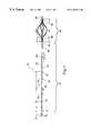
- FIG. 1shows a side view of a surgical device utilizing an embodiment of a retrieval basket according to this invention.
- FIG. 2shows a distal end view of the retrieval basket shown in FIG. 1 .
- FIG. 3shows a distal end view of another embodiment of a retrieval basket according to this invention.
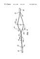
- FIG. 4shows a side view of a portion of the retrieval basket shown in FIGS. 1 and 2, illustrating preferred paths of two of the basket's wires.
- FIG. 5shows another side view of a portion of the retrieval basket shown in FIGS. 1 and 2, illustrating preferred paths of two of the basket's wires.
- FIG. 6shows a side view of a portion of another embodiment of a retrieval basket according to this invention, illustrating preferred paths of two of the basket's wires.
- the handlecan include a moveable thumb slide basket positioner that is connected to a cable that extends to the basket. The thumb slide permits the advancement and retraction of the basket with respect to the handle.
- a sheathis fixedly attached to the handle and remains stationary with respect to the handle.
- the handlecan include a mechanism for positioning a moveable sheath and the basket can be fixed with respect to the handle. In such a configuration, advancement of the moveable sheath collapses the basket and retraction of the sheath allows the basket to expand.
- FIG. 1illustrates a portion of a surgical device generally designated by the numeral “ 10 ” that incorporates aspects of this invention. It includes an elongated shaft 12 that is preferably flexible but can also be rigid. At a proximal end of shaft 12 (toward the left in FIG. 1) is provided a connector tube 14 formed from stainless steel or another suitable material. Connector tube 14 is provided with a length L 1 as well as inner diameter D 1 and outer diameter D 2 that are adapted for connection within a handle (not shown) as described earlier. Connector tube 14 is connected by means of a solder joint 16 to a twisted wire portion 18 .
- twisted wire portion 18includes six strands of wire wrapped around one to provide an overall outer diameter D 3 , although other wire configurations are contemplated such as braided wires, a solid monofilament, etc. Each wire has a diameter D 4 and is twisted with a relatively tight pitch P 1 with a large number of turns per unit length extending along a length L 2 of portion 18 .
- a solder joint 20connects twisted wire portion 18 to a connector tube 22 which, in turn, is connected by another solder joint 24 to a relaxed pitched portion 26 .
- Relaxed pitch portion 26is formed from eight wires in this embodiment twisted in a relatively relaxed pitch P 2 with a smaller number of turns per unit length. Relaxed pitch portion 26 is connected by means of another solder joint 28 to a connector tube 30 , which is positioned at the proximal end portion of elongated shaft 12 (toward the right side in FIG. 1 ).
- Additional shaft assembly embodimentsinclude the use of flexible tubular or solid non-braided members or plastic-encased metal. Other materials such as nickel-titanium alloy or rigid thermoplastic materials may also be used. Also, joining means other than solder can be used to connect various components of surgical device 10 together, including threaded connections, crimped connections, interference fits and other known joining means.
- a retrieval basket 34Connected to shaft 12 by means of a solder joint 32 is a retrieval basket 34 comprised of eight wires, details of which will be provided later.
- the number of wires used to form the basketmay or may not correspond to the number of wires used to form relaxed pitch portion 26 , depending on design and manufacturing considerations.
- Relaxed pitch portion 26 and other portions of shaft 12can alternatively be formed from a monofilament or hollow or solid rod.
- different quantities of wirescan be used to form the basket depending on the intended usage of the basket, the diameters of the wires selected for use in the device and manufacturing and cost considerations. This can be an odd number of wires although an even number is preferred.
- each “wire”is preferably a slender rod but can also take the form of a grouping of substantially parallel, braided, or twisted strands that share a substantially common path along the length of the basket as opposed to a solid wire.
- a solder joint 36connects a basket tip 38 that defines the distal end of retrieval basket 34 and the distal end of the surgical device 10 .
- the extreme tip of basket tip 38is preferably rounded or radiused or otherwise shaped to provide for atraumatic contact with the patient.
- Tip 38is optionally a short collar.
- tip 38is a straight or curved filiform tip that extends distally from the end of basket 34 .
- Such a filiform tipis preferably flexible so that it can be used for guidance of the basket through a patient's body passage and for negotiating and maneuvering the basket past a calculus to be grasped.
- Various structures and configurations for such filiform tipsare known in the art and the exact configuration of such a tip is not critical to this invention.
- Retrieval basket 34has a length L 3 between its proximal end at solder joint 32 and a wire pair diverging point which will be described later in more detail.
- the wires forming the retrieval baskethave an overall wire length L 4 in the basket and they are configured with a curvature that provides an overall basket length L 5 when the basket is in its expanded condition as shown in FIG. 1 .
- a sheathcan be moveably positioned over at least portions of shaft 12 and basket 34 to provide means for alternating or reciprocating basket 34 between an expanded position as shown in FIG. 1, a collapsed position within the sheath wherein the basket's wires are oriented adjacent to the basket's axis, and various positions between the expanded and collapsed positions for capturing a calculus.
- the sheathcan be eliminated.
- retrieval basket 34Details of retrieval basket 34 are shown in FIG. 2 in a distal end view. It includes eight wires 40 a - 40 h , which are alternately shown in solid and outline for clarity. As will be described more clearly with reference to FIGS. 4 and 6, the wires of this embodiment are preferably assembled so that they can be considered to be grouped in four pairs at the proximal end having two wires in each proximal pairing, i.e., wires 40 a and 40 b , wires 40 c and 40 d , wires 40 e and 40 f , and wires 40 g and 40 h .
- the wires 40 a - 40 hare formed so that they extend outwardly to a maximum achieved diameter D 5 , which is selected based on the intended use of the basket and the body passages through which it is intended to be inserted.
- the wires in each pairare preferably provided with substantially opposite curvilinear paths, preferable opposite helical paths, as will be described later in more detail.
- wire 40 aextends at least partially along a substantially counter-clockwise helical path while wire 40 b extends at least partially along a substantially clockwise helical path.
- the four proximal pairs of wiresare preferably separated by a uniform angle ⁇ 1 , which in this embodiment with four pairs of wires is about 90°.
- FIG. 3illustrates an alternative embodiment of a retrieval basket 134 that includes six wires 140 a - 140 f that are preferably grouped into one of three pairs at the proximal end (e.g., wires 140 a and 140 b , wires 140 c and 140 d , and wires 140 e and 140 f ).
- retrieval basket 134includes a rounded basket tip 138 and the wires are formed in such a way that they extend outwardly to a maximum achieved diameter D 6 .
- the wires in each proximal pairingare preferably provided with substantially opposite helical paths, and the wire pairs are preferably separated by a uniform angle ⁇ 2 , which in the three-pair embodiment in FIG. 3 is about 120°.
- FIG. 4illustrates details of a portion of the retrieval baskets at 34 shown in FIG. 2 as defined by the view “V—V” in that figure. Only the pair of wires 40 a and 40 b is shown for the sake of clarity. Both of the wires 40 a and 40 b extend from a proximal end 42 of the basket to a distal end 44 of the basket. Wires 40 a and 40 b extend along a substantially straight path that diverges radially outwardly from the central longitudinal axis of the basket in a proximal portion of retrieval basket 34 . In other words, in a proximal portion of the basket the wires can follow a path that is similar to that of the wires in a flat-wire basket.
- Wire 40 athen extends along a curvilinear path such as a counter-clockwise helix toward the distal portion of the basket.
- a curvilinear pathsuch as a counter-clockwise helix toward the distal portion of the basket.
- the wirescan follow a path that is similar to that of the wires in a helical basket. They descend and converge toward the basket's axis with a significant degree of curvature with respect to the plane occupied by the basket's axis.
- adjacent wiressuch as wires 40 a and 40 b
- wires 40 a and 40 bare preferably manufactured so that the curvatures in their respective distal portions are opposite or mirror images of one another such as in a clockwise helical direction (wire 40 b ) and a counter-clockwise direction (wire 40 a ). Accordingly, wire 40 b extends in a substantially straight ascending path in the basket's proximal portion and then assumes a clockwise helix toward the basket's distal portion.
- Wires 40 a and 40 bare preferably formed during the manufacturing process of the basket in order to have a virtually straight ascending portion of toward the proximal portion the basket that transitions into a descending helical path toward the distal portion of the basket. Nevertheless, when the retrieval basket 34 is in its expanded condition as shown in FIG. 2 and FIG. 4, the helix in the distal portion can be partially transferred from the distal portion into the proximal straight portion of the wires as the twisting forces and stresses in the wires are distributed along the basket's length. It has been discovered that this effect forms a unique “dual helix” or “dual helical path” configuration.
- the dual helixprovides a helical wire path toward the proximal portion of the basket that has a curvature with a very large radius.
- the helix in the proximal portionhas a very gentle pitch with a very small number of turns per unit length.
- Thisis contrasted with the helix toward the distal portion of the basket, which has a relatively tight curvature with a smaller radius and a tighter pitch with a larger number of turns per unit length.
- wires 40 a and 40 bextend along a proximal helical path having a curvature with a relatively large radius. This large radius of curvature can be seen between and adjacent to the crossing points 46 and 48 , which will be described in detail later.
- wires 40 a and 40 bextend along a distal helical path having a curvature with a relatively small radius in a distal portion of basket 34 toward distal end 44 . This smaller radius of curvature can be seen adjacent to crossing point 48 and extending to distal end 44 . As seen in FIG.
- each wire 40 a and 40 bincludes at least two maximums 43 a and 45 a on wire 40 a and 43 b and 45 b on wire 40 b . These maximums are between proximal end 42 and distal end 44 . Maximums 43 a and 43 b are in a proximal portion of basket 34 and maximums 45 a and 45 b are in a distal portion of basket 34 . Each maximum is a point where wires 40 a and 40 b reach a maximum separation from one another.
- wire kinks and bendscan be used to shape the wires along a path having an overall curvature.
- a multiplicity of small kinks or bendscan be used to form one or more of the wires along a generally curvilinear path.
- a single kink or bend or just a few kinks or bendscan be used.
- a kink or bendcan be provided in the wire between a proximal curvature of larger radius and a distal curvature of smaller radius.
- kinks or bendscan be used in conjunction with smooth curves to form the path of one or more of the wires. Whether or not kinks, bends and/or smooth curves are utilized depends on the manufacturing technique selected and the desired basket performance characteristics.
- wires 40 a and 40 bit has been discovered that it is beneficial for wires 40 a and 40 b to be formed so that they extend from the basket's proximal end 42 closely adjacent to one another as opposed to all of the wires being evenly spaced from one another. In order to accomplish this, adjacent wires can be radially positioned at or near the proximal end of the basket so that they will extend from the proximal end next to one another before diverging.
- the wire diverging pointis preferably at the midsection of the basket but may also be proximal or distal to the midsection.
- wires 40 a and 40 bdiverge from one another at a diverging point 47 .
- the distance between proximal end 42 and diverging point 47is at least about 40% of the distance between proximal end 42 and distal end 44 (length L 5 in FIG. 1 ), most preferably about 50% or more, although other proportions can be selected depending upon manufacturing considerations and the intended use of the basket.
- the exact or proportional distance of diverging point 47is not critical to the invention.
- wires 40 a and 40 bmay instead cross in front of wire 40 a at crossing points 46 and 48 .
- wires 40 a and 40 bcan cross over and then behind one another; i.e., wire 40 a can cross over wire 40 b at crossing point 46 and then under wire 40 b at crossing point 48 , or wire 40 b can cross over wire 40 a at crossing point 46 and then under wire 40 a at crossing point 48 . Accordingly, wires 40 a and 40 b can be twisted or wrapped with respect to one another.
- the crossing points 46 and 48are not critical to the invention as will be described later with reference to FIG. 6 . However, it has been discovered that the first and second crossing points 46 and 48 tend to provide contact points for mutual support between wires 40 a and 40 b and that such support actually serves to strengthen the retrieval basket 34 . A crossing structure also tends to increase the radial dilatation force and radial opening force that can be exerted radially outwardly by the retrieval basket against an inner wall of a patient's duct such as a ureter.
- Increased dilatation forcecan be extremely beneficial to the performance of the basket and to the ease with which the retrieval basket is used because the basket can actually dilate the patient's duct at a location corresponding to a calculus so that it can be more easily surrounded by the basket.
- FIG. 5illustrates wires 40 b and 40 c that form a part of retrieval basket 34 as indicated in FIG. 2, and defined by the view “VI—VI” in FIG. 2 .
- wires 40 b and 40 cextend from the basket's proximal end 42 in substantially straight paths that ascend radially outwardly away from the basket's axis, but wires 40 b and 40 c are positioned radially with respect to one another so that they separate or diverge away from one another from the start. Wires 40 b and 40 c later converge toward one another toward the distal portion of the basket as a result of their increased curvature in that portion. As shown in FIG.
- crossing points 50 and 52are near to the distal end of the basket.
- crossing points 50 and 52tend to add strength to the retrieval basket 34 and to improve the dilatation force exertable by the basket when it is in its expanded position.
- crossing points 50 and 52can provide a twisting or wrapping configuration between wires 40 b and 40 c if wire 40 b first crosses under and then over wire 40 c or if wire 40 c first crosses under and then over wire 40 b.
- wires 40 a and 40 bare preferably positioned closely adjacent to one another as a pair in the proximal portion of the basket and define a relatively small space 37 (FIG. 4) at the distal portion of the basket through which calculi cannot easily pass.
- the separation of wire 40 b from wire 40 c in the proximal region of the basketdefines a larger gap 35 in that portion through which calculi can easily pass.
- Such a wider gap 35 near the proximal portion of retrieval basket 34permits calculi to ingress with ease into the interior region of the expanded basket as the basket is drawn in the proximal direction to capture a calculus.
- gap 35could also permit the intentional egress or deployment of a captured calculus from retrieval basket 34 upon the distal advancement of the basket in the expanded position if it is discovered that the captured calculus is too large in some dimension to be easily extracted from the patient.
- the space 37 toward the distal end of retrieval basket 34 between wires 40 a and 40 bis significantly smaller in size as compared to gap 35 between wires 40 b and 40 c , thereby preventing the inadvertent escape of a calculus from the interior of the retrieval basket through space 37 as the basket is moved from its expanded position toward its collapsed position by manipulation with respect to the sheath in order to firmly capture the calculus.
- Thisis due in part to greater wire-calculi contact points for calculi entrapment and retention.
- larger gap 35facilitates the ingress of a calculus, or could facilitate the intentional deployment of the calculus, while the basket is expanded.
- FIGS. 4 and 5also illustrate that retrieval basket 34 is preferably asymmetrical along its length, which results in the significant disparity between the relative size of gap 35 as compared to space 37 .
- the distance between proximal end 42 of basket 34 and the second crossing point 48 between wires 40 a and 40 bis significantly larger than the distance between distal end 44 of basket 34 and the first crossing point 50 between wires 40 b and 40 c .
- the length L 3 between proximal end 42 and diverging point 47 between wires 40 a and 40 bis significantly larger than the distance between a converging point 51 (FIG. 5) between wires 40 b and 40 c and distal end 44 .
- FIG. 6illustrates another embodiment of a retrieval basket according to this invention, generally designated by the numeral “ 334 ”. Like the others, this embodiment includes a connector tube 330 and solder joint 332 at proximal end 342 of the basket. Wires 340 a and 340 b corresponding generally in position to wires 40 a and 40 b (as shown in FIGS. 2 and 4) extend from the basket's proximal end 342 to a distal end 344 . A solder joint connection 336 is made between the wires and a rounded basket tip 338 .
- adjacent wires 340 a and 340 bpreferably never cross one another along the entire length of the basket. Instead, they extend from the basket's proximal end 342 generally parallel and closely adjacent to one another and in a substantially straight path as they ascend radially away from the basket's axis, only slightly separating sidewardly away from one another if at all as they extend longitudinally from the basket's proximal end 342 . Although they are shown to be parallel and virtually touching in FIG. 6, it is clearly contemplated that wires 340 a and 340 b will separate from one another at a small angle to define a narrow “V” between them before they diverge.
- wires 340 a and 340 bdiverge sharply from one another at diverging point 347 along curved paths, such as helical paths, that are different from one another, preferably of opposite hands.
- the description of diverging point 47 with reference to FIG. 4applies to diverging point 347 as well.
- Wires 340 a and 340 bcan optionally be connected to one another at a point proximal of diverging point 347 to maintain their parallel configuration in the proximal portion of the basket.
- retrieval basket 334enjoys the advantages of basket 34 in that large proximal gaps such as gap 35 are provided at the proximal portion of the retrieval basket 334 and a smaller distal space such as space 337 is provided toward the basket's distal end. This of course facilitates calculus ingress into the basket and firm calculus capture within the basket when the basket is closed around a calculus for extraction. It can also help to facilitate intentional calculus deployment from the basket when desired.
- basket 334preferably does not include any crossing points between wires 340 a and 340 b near the proximal end of the basket.
- wires 40 a and 40 bare very much like wires 340 a and 340 b in that they extend substantially parallel to one another in the basket's proximal portion.
- the exact configuration of the wires of a retrieval basket according to this inventionwill vary according to the materials selected for the wires, the wire diameters selected and the method selected to form the wires into the shape of the retrieval basket.
- work-hardened 300 series stainless steel, nickel-titanium alloy, chromium-cobalt alloy and other similar materialsare preferred materials for forming the wires, other suitable metallic or polymeric materials can be substituted.
- wire diameters and circular or non-circular cross-sectional shapescan be used, a diameter of about 0.007-inch has been found to form a flexible basket with an advantageous dilatation force, although other wire diameters may be beneficial for a particular application.
- various methodsare known in the art for forming wire baskets such as those described in Bates et al. U.S. Pat. No. 5,658,296, which is incorporated herein by reference.
- the wires illustrated in the figuresinclude wires with helical paths in alternating directions
- the wirescan optionally follow substantially parallel yet diverging paths that may or may not cross one another.
- the wirescan follow relatively straight and parallel paths in the proximal portion of the basket and diverge into relatively helical and parallel paths in the distal portion.
Landscapes
- Health & Medical Sciences (AREA)
- Surgery (AREA)
- Life Sciences & Earth Sciences (AREA)
- Heart & Thoracic Surgery (AREA)
- Nuclear Medicine, Radiotherapy & Molecular Imaging (AREA)
- Vascular Medicine (AREA)
- Engineering & Computer Science (AREA)
- Biomedical Technology (AREA)
- Orthopedic Medicine & Surgery (AREA)
- Medical Informatics (AREA)
- Molecular Biology (AREA)
- Animal Behavior & Ethology (AREA)
- General Health & Medical Sciences (AREA)
- Public Health (AREA)
- Veterinary Medicine (AREA)
- Surgical Instruments (AREA)
Abstract
Description
Claims (56)
Priority Applications (1)
| Application Number | Priority Date | Filing Date | Title |
|---|---|---|---|
| US09/025,099US6187017B1 (en) | 1998-02-17 | 1998-02-17 | Retrieval basket for a surgical device |
Applications Claiming Priority (1)
| Application Number | Priority Date | Filing Date | Title |
|---|---|---|---|
| US09/025,099US6187017B1 (en) | 1998-02-17 | 1998-02-17 | Retrieval basket for a surgical device |
Publications (1)
| Publication Number | Publication Date |
|---|---|
| US6187017B1true US6187017B1 (en) | 2001-02-13 |
Family
ID=21824064
Family Applications (1)
| Application Number | Title | Priority Date | Filing Date |
|---|---|---|---|
| US09/025,099Expired - LifetimeUS6187017B1 (en) | 1998-02-17 | 1998-02-17 | Retrieval basket for a surgical device |
Country Status (1)
| Country | Link |
|---|---|
| US (1) | US6187017B1 (en) |
Cited By (41)
| Publication number | Priority date | Publication date | Assignee | Title |
|---|---|---|---|---|
| US20020010476A1 (en)* | 1999-01-28 | 2002-01-24 | Patrick Mulholland | Catheter with an expandable end portion |
| US6348056B1 (en) | 1999-08-06 | 2002-02-19 | Scimed Life Systems, Inc. | Medical retrieval device with releasable retrieval basket |
| US6350266B1 (en)* | 1995-02-02 | 2002-02-26 | Scimed Life Systems, Inc. | Hybrid stone retrieval device |
| US20020107526A1 (en)* | 2000-11-03 | 2002-08-08 | Cook Incorporated | Medical grasping device |
| JP2002253558A (en)* | 2001-03-01 | 2002-09-10 | Asahi Optical Co Ltd | Endoscope basket type retrieval tool |
| JP2002253559A (en)* | 2001-03-01 | 2002-09-10 | Asahi Optical Co Ltd | Wire loop type treatment instrument for endoscope |
| US20030135228A1 (en)* | 2002-01-16 | 2003-07-17 | Healthy Enterprises, Llc | Ear cleaning appliance and method of manufacture |
| US20030181842A1 (en)* | 2002-03-19 | 2003-09-25 | Scimed Life Systems, Inc. | Stent retention element and related methods |
| US6673080B2 (en) | 2001-01-08 | 2004-01-06 | Scimed Life Systems, Inc. | Retrieval basket with releasable tip |
| US20040138677A1 (en)* | 2003-01-15 | 2004-07-15 | Scimed Life Systems, Inc. | Medical retrieval device with frangible basket |
| US20040199200A1 (en)* | 2003-04-07 | 2004-10-07 | Scimed Life Systems, Inc. | Beaded basket retrieval device |
| US20040215212A1 (en)* | 2003-04-24 | 2004-10-28 | Teague James A. | Retractable grasper |
| US20040236345A1 (en)* | 2000-11-03 | 2004-11-25 | Greenberg Roy K. | Medical grasping device |
| US20040243174A1 (en)* | 2000-11-03 | 2004-12-02 | Ackerman Andrew J. | Medical grasping device having embolic protection |
| US20050043756A1 (en)* | 2003-07-31 | 2005-02-24 | Vance Products Incorporated D/B/A Cook Urological Incorporated | Ureteral backstop filter and retrieval device |
| US20050049612A1 (en)* | 2000-11-03 | 2005-03-03 | Jason Urbanski | Medical grasping device |
| US20060058813A1 (en)* | 2004-09-15 | 2006-03-16 | Scimed Life Systems | Atraumatic medical device |
| US20060130332A1 (en)* | 2002-03-13 | 2006-06-22 | Scimed Life Systems, Inc. | Filter frame |
| DE102006002531A1 (en)* | 2006-01-11 | 2007-07-12 | Epflex Feinwerktechnik Gmbh | Multiwire instrument, in particular for endoscopes |
| US20070167974A1 (en)* | 2006-01-13 | 2007-07-19 | Cully Edward H | Removable blood conduit filter |
| US20070213634A1 (en)* | 2006-02-24 | 2007-09-13 | Boston Scientific Scimed, Inc. | Obtaining a tissue sample |
| US20070239141A1 (en)* | 2000-11-03 | 2007-10-11 | William A. Cook Australia Pty Ltd. | Medical grasping device |
| US20070260266A1 (en)* | 2006-05-03 | 2007-11-08 | Cook Incorporated | Lithotripsy compatible wire basket |
| US20080086171A1 (en)* | 2006-10-05 | 2008-04-10 | Knapp Thomas P | Shape memory filament for suture management |
| US20080086149A1 (en)* | 2006-10-06 | 2008-04-10 | Cook Incorporated | Retrieval snare for extracting foreign objects from body cavities and method for manufacturing thereof |
| US20080086147A1 (en)* | 2006-10-05 | 2008-04-10 | Knapp Thomas P | Shape memory filament for suture management |
| US20080125855A1 (en)* | 2002-07-19 | 2008-05-29 | Hans Henkes | Medical implant having a curlable matrix structure |
| US20080269774A1 (en)* | 2006-10-26 | 2008-10-30 | Chestnut Medical Technologies, Inc. | Intracorporeal Grasping Device |
| US20110060212A1 (en)* | 2008-02-22 | 2011-03-10 | Micro Therapeutics, Inc. | Methods and apparatus for flow restoration |
| EP2638870A4 (en)* | 2011-04-13 | 2013-11-27 | Olympus Medical Systems Corp | ENDOSCOPIC TREATMENT INSTRUMENT |
| DE102012222356A1 (en)* | 2012-12-05 | 2014-06-05 | Epflex Feinwerktechnik Gmbh | Medical safety wire instrument |
| US8858569B2 (en) | 2012-02-16 | 2014-10-14 | Shaw P. Wan | Stone retrieval device |
| US9039749B2 (en) | 2010-10-01 | 2015-05-26 | Covidien Lp | Methods and apparatuses for flow restoration and implanting members in the human body |
| CN105578974A (en)* | 2013-12-12 | 2016-05-11 | 奥林巴斯株式会社 | Basket-type gripping forceps |
| US10076399B2 (en) | 2013-09-13 | 2018-09-18 | Covidien Lp | Endovascular device engagement |
| US10413310B2 (en) | 2007-10-17 | 2019-09-17 | Covidien Lp | Restoring blood flow and clot removal during acute ischemic stroke |
| WO2020136755A1 (en)* | 2018-12-26 | 2020-07-02 | オリンパス株式会社 | Endoscopic treatment instrument |
| US10722255B2 (en) | 2008-12-23 | 2020-07-28 | Covidien Lp | Systems and methods for removing obstructive matter from body lumens and treating vascular defects |
| USD943743S1 (en)* | 2019-01-15 | 2022-02-15 | Olympus Corporation | Stone retrieval basket for medical device |
| US11337714B2 (en) | 2007-10-17 | 2022-05-24 | Covidien Lp | Restoring blood flow and clot removal during acute ischemic stroke |
| US11504143B2 (en) | 2018-06-28 | 2022-11-22 | Olympus Corporation | Endoscope treatment tool |
Citations (11)
| Publication number | Priority date | Publication date | Assignee | Title |
|---|---|---|---|---|
| SU240173A1 (en)* | В. П. Пашковский | EXTRACTOR V.P. PASHKOVSKY TO REMOVE STONES FROM THE URIN | ||
| US4425908A (en) | 1981-10-22 | 1984-01-17 | Beth Israel Hospital | Blood clot filter |
| EP0123175A1 (en) | 1983-04-16 | 1984-10-31 | Knut Dr. Korth | Catheter for removing calculus from the kidneys or urethra |
| EP0160870A2 (en) | 1984-05-04 | 1985-11-13 | Boston Scientific Corporation | Medical retriever device |
| EP0391384A2 (en)* | 1989-04-05 | 1990-10-10 | GIP Medizintechnik GmbH | Lithotriptor |
| US5057114A (en) | 1990-09-18 | 1991-10-15 | Cook Incorporated | Medical retrieval basket |
| US5133733A (en) | 1989-11-28 | 1992-07-28 | William Cook Europe A/S | Collapsible filter for introduction in a blood vessel of a patient |
| WO1992016153A1 (en) | 1991-03-19 | 1992-10-01 | Roevin Trades Limited | Extraction devices |
| US5330482A (en) | 1991-06-17 | 1994-07-19 | Wilson-Cook Medical Inc. | Endoscopic extraction devices, wire basket stone extractors, stent retrievers, snares and method of constructing the same |
| US5484384A (en) | 1991-01-29 | 1996-01-16 | Med Institute, Inc. | Minimally invasive medical device for providing a radiation treatment |
| WO1996015728A1 (en) | 1994-11-21 | 1996-05-30 | Boston Scientific Corporation | Surgical retrieval baskets and method for making the same |
- 1998
- 1998-02-17USUS09/025,099patent/US6187017B1/ennot_activeExpired - Lifetime
Patent Citations (12)
| Publication number | Priority date | Publication date | Assignee | Title |
|---|---|---|---|---|
| SU240173A1 (en)* | В. П. Пашковский | EXTRACTOR V.P. PASHKOVSKY TO REMOVE STONES FROM THE URIN | ||
| US4425908A (en) | 1981-10-22 | 1984-01-17 | Beth Israel Hospital | Blood clot filter |
| EP0123175A1 (en) | 1983-04-16 | 1984-10-31 | Knut Dr. Korth | Catheter for removing calculus from the kidneys or urethra |
| EP0160870A2 (en) | 1984-05-04 | 1985-11-13 | Boston Scientific Corporation | Medical retriever device |
| EP0391384A2 (en)* | 1989-04-05 | 1990-10-10 | GIP Medizintechnik GmbH | Lithotriptor |
| US5133733A (en) | 1989-11-28 | 1992-07-28 | William Cook Europe A/S | Collapsible filter for introduction in a blood vessel of a patient |
| US5057114A (en) | 1990-09-18 | 1991-10-15 | Cook Incorporated | Medical retrieval basket |
| US5484384A (en) | 1991-01-29 | 1996-01-16 | Med Institute, Inc. | Minimally invasive medical device for providing a radiation treatment |
| WO1992016153A1 (en) | 1991-03-19 | 1992-10-01 | Roevin Trades Limited | Extraction devices |
| US5330482A (en) | 1991-06-17 | 1994-07-19 | Wilson-Cook Medical Inc. | Endoscopic extraction devices, wire basket stone extractors, stent retrievers, snares and method of constructing the same |
| WO1996015728A1 (en) | 1994-11-21 | 1996-05-30 | Boston Scientific Corporation | Surgical retrieval baskets and method for making the same |
| US5792145A (en)* | 1994-11-21 | 1998-08-11 | Boston Scientific Corporation | Surgical retrieval baskets |
Non-Patent Citations (1)
| Title |
|---|
| English translation of Russian Patent No. 240173 of V.P. Pashkovskiy for Gallstone Extractor. |
Cited By (107)
| Publication number | Priority date | Publication date | Assignee | Title |
|---|---|---|---|---|
| US6350266B1 (en)* | 1995-02-02 | 2002-02-26 | Scimed Life Systems, Inc. | Hybrid stone retrieval device |
| US8828022B2 (en) | 1995-02-02 | 2014-09-09 | Boston Scientific Scimed, Inc. | Hybrid stone retrieval device |
| US20050216031A1 (en)* | 1995-02-02 | 2005-09-29 | Boston Scientific Scimed, Inc. | Hybrid stone retrieval device |
| US6872211B2 (en) | 1995-02-02 | 2005-03-29 | Scimed Life Systems, Inc. | Hybrid stone retrieval device |
| US20060264972A1 (en)* | 1999-01-28 | 2006-11-23 | Salviac Limited | Catheter with an expandable end portion |
| US7094243B2 (en)* | 1999-01-28 | 2006-08-22 | Salviac Limited | Catheter with an expandable end portion |
| US20020010476A1 (en)* | 1999-01-28 | 2002-01-24 | Patrick Mulholland | Catheter with an expandable end portion |
| US7837692B2 (en) | 1999-01-28 | 2010-11-23 | Salviac Limited | Catheter with an expandable end portion |
| US20040073230A1 (en)* | 1999-01-28 | 2004-04-15 | Ansamed Limited | Catheter with an expandable end portion |
| US6348056B1 (en) | 1999-08-06 | 2002-02-19 | Scimed Life Systems, Inc. | Medical retrieval device with releasable retrieval basket |
| US20070239141A1 (en)* | 2000-11-03 | 2007-10-11 | William A. Cook Australia Pty Ltd. | Medical grasping device |
| US7753918B2 (en) | 2000-11-03 | 2010-07-13 | William A. Cook Australia Pty. Ltd. | Medical grasping device |
| US7776052B2 (en) | 2000-11-03 | 2010-08-17 | Cook Incorporated | Medical grasping device |
| US7727253B2 (en) | 2000-11-03 | 2010-06-01 | Cook Incorporated | Medical grasping device having embolic protection |
| US20040236345A1 (en)* | 2000-11-03 | 2004-11-25 | Greenberg Roy K. | Medical grasping device |
| US20040243174A1 (en)* | 2000-11-03 | 2004-12-02 | Ackerman Andrew J. | Medical grasping device having embolic protection |
| US7713275B2 (en) | 2000-11-03 | 2010-05-11 | Cook Incorporated | Medical grasping device |
| US20050049612A1 (en)* | 2000-11-03 | 2005-03-03 | Jason Urbanski | Medical grasping device |
| US7753917B2 (en) | 2000-11-03 | 2010-07-13 | Cook Incorporated | Medical grasping device |
| US20020107526A1 (en)* | 2000-11-03 | 2002-08-08 | Cook Incorporated | Medical grasping device |
| US20100106164A1 (en)* | 2001-01-08 | 2010-04-29 | Boston Scientific Scimed, Inc. | Retrieval Basket with Releasable Tip |
| US20040116941A1 (en)* | 2001-01-08 | 2004-06-17 | Scimed Life Systems, Inc. | Retrieval basket with releasable tip |
| US7645283B2 (en) | 2001-01-08 | 2010-01-12 | Boston Scientific Scimed, Inc. | Retrieval basket with releasable tip |
| US6673080B2 (en) | 2001-01-08 | 2004-01-06 | Scimed Life Systems, Inc. | Retrieval basket with releasable tip |
| JP2002253559A (en)* | 2001-03-01 | 2002-09-10 | Asahi Optical Co Ltd | Wire loop type treatment instrument for endoscope |
| JP2002253558A (en)* | 2001-03-01 | 2002-09-10 | Asahi Optical Co Ltd | Endoscope basket type retrieval tool |
| US6939360B2 (en)* | 2002-01-16 | 2005-09-06 | Healthy Enterprises | Ear cleaning appliance and method of manufacture |
| US20030135228A1 (en)* | 2002-01-16 | 2003-07-17 | Healthy Enterprises, Llc | Ear cleaning appliance and method of manufacture |
| US20060130332A1 (en)* | 2002-03-13 | 2006-06-22 | Scimed Life Systems, Inc. | Filter frame |
| US8328877B2 (en) | 2002-03-19 | 2012-12-11 | Boston Scientific Scimed, Inc. | Stent retention element and related methods |
| US20030181842A1 (en)* | 2002-03-19 | 2003-09-25 | Scimed Life Systems, Inc. | Stent retention element and related methods |
| US20080125855A1 (en)* | 2002-07-19 | 2008-05-29 | Hans Henkes | Medical implant having a curlable matrix structure |
| US8632584B2 (en) | 2002-07-19 | 2014-01-21 | Dendron Gmbh | Medical implant having a curlable matrix structure and method of use |
| US10342683B2 (en) | 2002-07-19 | 2019-07-09 | Ussc Medical Gmbh | Medical implant having a curlable matrix structure and method of use |
| US11426293B2 (en) | 2002-07-19 | 2022-08-30 | Ussc Medical Gmbh | Medical implant |
| US8685039B2 (en) | 2003-01-15 | 2014-04-01 | Boston Scientific Scimed, Inc. | Medical retrieval device with frangible basket |
| US20040138677A1 (en)* | 2003-01-15 | 2004-07-15 | Scimed Life Systems, Inc. | Medical retrieval device with frangible basket |
| US20110028987A1 (en)* | 2003-01-15 | 2011-02-03 | Boston Scientific Scientific Scimed, Inc. | Medical retrieval device with frangible basket |
| US7678119B2 (en) | 2003-01-15 | 2010-03-16 | Scimed Life Systems, Inc. | Medical retrieval device with frangible basket |
| US20040199200A1 (en)* | 2003-04-07 | 2004-10-07 | Scimed Life Systems, Inc. | Beaded basket retrieval device |
| US7559934B2 (en)* | 2003-04-07 | 2009-07-14 | Scimed Life Systems, Inc. | Beaded basket retrieval device |
| US7322989B2 (en) | 2003-04-24 | 2008-01-29 | Boston Scientific Scimed, Inc. | Retractable grasper |
| US20040215212A1 (en)* | 2003-04-24 | 2004-10-28 | Teague James A. | Retractable grasper |
| US20050043756A1 (en)* | 2003-07-31 | 2005-02-24 | Vance Products Incorporated D/B/A Cook Urological Incorporated | Ureteral backstop filter and retrieval device |
| US7731722B2 (en) | 2003-07-31 | 2010-06-08 | Vance Products Incorporated | Ureteral backstop filter and retrieval device |
| US20060058813A1 (en)* | 2004-09-15 | 2006-03-16 | Scimed Life Systems | Atraumatic medical device |
| US7824415B2 (en) | 2004-09-15 | 2010-11-02 | Boston Scientific Scimed, Inc. | Atraumatic medical device |
| US8911449B2 (en) | 2004-09-15 | 2014-12-16 | Boston Scientific Scimed, Inc. | Atraumatic medical device |
| US20110066158A1 (en)* | 2004-09-15 | 2011-03-17 | Scimed Life Systems, Inc. | Atraumatic medical device |
| WO2007082671A1 (en)* | 2006-01-11 | 2007-07-26 | Epflex Feinwerktechnik Gmbh | Multi-wire instrument, in particular for endoscopes |
| US20100168758A1 (en)* | 2006-01-11 | 2010-07-01 | Epflex Feinwerktechnik Gmbh | Multi-Wire Instrument, In Particular for Endoscopes |
| DE102006002531A1 (en)* | 2006-01-11 | 2007-07-12 | Epflex Feinwerktechnik Gmbh | Multiwire instrument, in particular for endoscopes |
| US8852203B2 (en) | 2006-01-11 | 2014-10-07 | Epflex Feinwerktechnik Gmbh | Multi-wire instrument, in particular for endoscopes |
| US9107733B2 (en)* | 2006-01-13 | 2015-08-18 | W. L. Gore & Associates, Inc. | Removable blood conduit filter |
| US20070167974A1 (en)* | 2006-01-13 | 2007-07-19 | Cully Edward H | Removable blood conduit filter |
| US20090131826A1 (en)* | 2006-02-24 | 2009-05-21 | Boston Scientific Scimed, Inc. | Obtaining a tissue sample |
| US7828746B2 (en) | 2006-02-24 | 2010-11-09 | Boston Scientific Scimed, Inc. | Obtaining a tissue sample |
| US7473232B2 (en) | 2006-02-24 | 2009-01-06 | Boston Scientific Scimed, Inc. | Obtaining a tissue sample |
| US20070213634A1 (en)* | 2006-02-24 | 2007-09-13 | Boston Scientific Scimed, Inc. | Obtaining a tissue sample |
| US20070260266A1 (en)* | 2006-05-03 | 2007-11-08 | Cook Incorporated | Lithotripsy compatible wire basket |
| WO2007131100A1 (en)* | 2006-05-03 | 2007-11-15 | Wilson-Cook Medical, Inc. | Lithotripsy compatible wire basket |
| AU2007308005B2 (en)* | 2006-10-05 | 2013-10-10 | Timothy Coonahan | Shape memory filament for suture management |
| US20110098729A1 (en)* | 2006-10-05 | 2011-04-28 | Knapp Thomas P | Shape memory filament for suture management |
| US20080086147A1 (en)* | 2006-10-05 | 2008-04-10 | Knapp Thomas P | Shape memory filament for suture management |
| US9072514B2 (en)* | 2006-10-05 | 2015-07-07 | Thomas P. Knapp | Shape memory filament for suture management |
| US8579923B2 (en) | 2006-10-05 | 2013-11-12 | Thomas P. Knapp | Shape memory filament for suture management |
| US10869661B2 (en) | 2006-10-05 | 2020-12-22 | Depuy Mitek, Llc | Shape memory filament for suture management |
| US8282658B2 (en) | 2006-10-05 | 2012-10-09 | Knapp Thomas P | Shape memory filament for suture management |
| US20080086171A1 (en)* | 2006-10-05 | 2008-04-10 | Knapp Thomas P | Shape memory filament for suture management |
| US20110098742A1 (en)* | 2006-10-05 | 2011-04-28 | Knapp Thomas P | Shape memory filament for suture management |
| US20110098726A1 (en)* | 2006-10-05 | 2011-04-28 | Knapp Thomas P | Shape memory filament for suture management |
| US9999420B2 (en) | 2006-10-05 | 2018-06-19 | Depuy Mitek, Llc | Shape memory filament for suture management |
| US10201846B2 (en) | 2006-10-06 | 2019-02-12 | Nordson Corporation | Retrieval snare for extracting foreign objects from body cavities and method for manufacturing thereof |
| US20080086149A1 (en)* | 2006-10-06 | 2008-04-10 | Cook Incorporated | Retrieval snare for extracting foreign objects from body cavities and method for manufacturing thereof |
| US9271746B2 (en) | 2006-10-06 | 2016-03-01 | Cook Medical Technologies Llc | Retrieval snare for extracting foreign objects from body cavities and method for manufacturing thereof |
| US8298244B2 (en) | 2006-10-26 | 2012-10-30 | Tyco Healtcare Group Lp | Intracorporeal grasping device |
| US20080269774A1 (en)* | 2006-10-26 | 2008-10-30 | Chestnut Medical Technologies, Inc. | Intracorporeal Grasping Device |
| US20100331853A1 (en)* | 2006-10-26 | 2010-12-30 | Chestnut Medical Technologies, Inc. | Intracorporeal grasping device |
| US10413310B2 (en) | 2007-10-17 | 2019-09-17 | Covidien Lp | Restoring blood flow and clot removal during acute ischemic stroke |
| US11337714B2 (en) | 2007-10-17 | 2022-05-24 | Covidien Lp | Restoring blood flow and clot removal during acute ischemic stroke |
| US8940003B2 (en) | 2008-02-22 | 2015-01-27 | Covidien Lp | Methods and apparatus for flow restoration |
| US9161766B2 (en) | 2008-02-22 | 2015-10-20 | Covidien Lp | Methods and apparatus for flow restoration |
| US10456151B2 (en) | 2008-02-22 | 2019-10-29 | Covidien Lp | Methods and apparatus for flow restoration |
| US11529156B2 (en) | 2008-02-22 | 2022-12-20 | Covidien Lp | Methods and apparatus for flow restoration |
| US8679142B2 (en) | 2008-02-22 | 2014-03-25 | Covidien Lp | Methods and apparatus for flow restoration |
| US20110060212A1 (en)* | 2008-02-22 | 2011-03-10 | Micro Therapeutics, Inc. | Methods and apparatus for flow restoration |
| US10722255B2 (en) | 2008-12-23 | 2020-07-28 | Covidien Lp | Systems and methods for removing obstructive matter from body lumens and treating vascular defects |
| US9039749B2 (en) | 2010-10-01 | 2015-05-26 | Covidien Lp | Methods and apparatuses for flow restoration and implanting members in the human body |
| US10426644B2 (en) | 2010-10-01 | 2019-10-01 | Covidien Lp | Methods and apparatuses for flow restoration and implanting members in the human body |
| EP2638870A4 (en)* | 2011-04-13 | 2013-11-27 | Olympus Medical Systems Corp | ENDOSCOPIC TREATMENT INSTRUMENT |
| US20140012283A1 (en)* | 2011-04-13 | 2014-01-09 | Olympus Medical Systems Corp. | Endoscope treatment tool |
| US9198682B2 (en)* | 2011-04-13 | 2015-12-01 | Olympus Corporation | Endoscope treatment tool |
| US8858569B2 (en) | 2012-02-16 | 2014-10-14 | Shaw P. Wan | Stone retrieval device |
| DE102012222356A1 (en)* | 2012-12-05 | 2014-06-05 | Epflex Feinwerktechnik Gmbh | Medical safety wire instrument |
| WO2014086917A1 (en)* | 2012-12-05 | 2014-06-12 | Epflex Feinwerktechnik Gmbh | Medical catching-wire instrument |
| DE102012222356B4 (en)* | 2012-12-05 | 2017-03-16 | Epflex Feinwerktechnik Gmbh | Medical stone catcher instrument |
| US11304712B2 (en) | 2013-09-13 | 2022-04-19 | Covidien Lp | Endovascular device engagement |
| US10076399B2 (en) | 2013-09-13 | 2018-09-18 | Covidien Lp | Endovascular device engagement |
| CN105578974B (en)* | 2013-12-12 | 2019-07-02 | 奥林巴斯株式会社 | Stone basket type holds pliers |
| US9775634B2 (en) | 2013-12-12 | 2017-10-03 | Olympus Corporation | Basket-type grasping forceps |
| EP3081177A4 (en)* | 2013-12-12 | 2017-08-30 | Olympus Corporation | Basket-type gripping forceps |
| CN105578974A (en)* | 2013-12-12 | 2016-05-11 | 奥林巴斯株式会社 | Basket-type gripping forceps |
| US11504143B2 (en) | 2018-06-28 | 2022-11-22 | Olympus Corporation | Endoscope treatment tool |
| WO2020136755A1 (en)* | 2018-12-26 | 2020-07-02 | オリンパス株式会社 | Endoscopic treatment instrument |
| US12245783B2 (en) | 2018-12-26 | 2025-03-11 | Olympus Corporation | Endoscopic treatment tool |
| USD943743S1 (en)* | 2019-01-15 | 2022-02-15 | Olympus Corporation | Stone retrieval basket for medical device |
| USD1043981S1 (en) | 2019-01-15 | 2024-09-24 | Olympus Corporation | Stone retrieval basket for medical device |
Similar Documents
| Publication | Publication Date | Title |
|---|---|---|
| US6187017B1 (en) | Retrieval basket for a surgical device | |
| US7101379B2 (en) | Retrieval basket for a surgical device and system and method for manufacturing same | |
| US6348056B1 (en) | Medical retrieval device with releasable retrieval basket | |
| US9808270B2 (en) | Medical retrieval devices and methods | |
| US6872211B2 (en) | Hybrid stone retrieval device | |
| JP3758962B2 (en) | Endoscope basket-type collection tool | |
| US8034075B2 (en) | Tethered coil for treatment of body lumens | |
| US8382771B2 (en) | Radial coil expandable medical wire | |
| US7875038B2 (en) | Releasable basket and method of making thereof | |
| US20070118165A1 (en) | System and method for removal of material from a blood vessel using a small diameter catheter | |
| JP2018519912A (en) | Recovery device and method of use related thereto | |
| US20060229638A1 (en) | Articulating retrieval device | |
| EP3041420B1 (en) | Medical retrieval devices | |
| KR20010041961A (en) | Minimally Invasive Medical Retrieval Device | |
| US9737319B2 (en) | Anti-retropulsion systems and methods | |
| WO1995031149A1 (en) | Dual coil medical retrieval device | |
| US9795401B2 (en) | Medical retrieval devices and related methods of use | |
| AU766024C (en) | Releasable basket and method of making thereof | |
| WO2002078632A2 (en) | Retrieval basket for a surgical device and system and method for manufacturing same | |
| JP4297468B2 (en) | Endoscopic basket-type collection tool | |
| JP7090104B2 (en) | Basket catheter | |
| EP4501254A1 (en) | Mesh basket body and calculus removing mesh basket | |
| JP2025531523A (en) | Catheter with a distal braided termination | |
| GB2321192A (en) | Endoscopic Dormian foreign body extractor |
Legal Events
| Date | Code | Title | Description |
|---|---|---|---|
| AS | Assignment | Owner name:CABOT TECHNOLOGY CORPORATION, A CORPORATION OF DEL Free format text:ASSIGNMENT OF ASSIGNORS INTEREST;ASSIGNOR:GREGORY, JR., FRANKLIN P.;REEL/FRAME:009028/0810 Effective date:19980226 | |
| AS | Assignment | Owner name:CHASE MANHATTAN BANK, THE, AS COLLATERAL AGENT, NE Free format text:SECURITY AGREEMENT;ASSIGNOR:CIRCON CORPORATION;REEL/FRAME:011122/0530 Effective date:19991112 | |
| STCF | Information on status: patent grant | Free format text:PATENTED CASE | |
| AS | Assignment | Owner name:ACMI CORPORATION, MASSACHUSETTS Free format text:CHANGE OF NAME;ASSIGNOR:CIRCON CORPORATION;REEL/FRAME:013295/0416 Effective date:20011227 | |
| AS | Assignment | Owner name:JPMORGAN CHASE BANK, AS COLLATERAL AGENT, NEW YORK Free format text:SUPPLEMENT;ASSIGNOR:ACMI CORPORATION;REEL/FRAME:013653/0347 Effective date:20030110 | |
| AS | Assignment | Owner name:ANTARES CAPITAL CORPORATION, AS AGENT, ILLINOIS Free format text:SECURITY INTEREST;ASSIGNOR:ACMI CORPORATION;REEL/FRAME:014815/0179 Effective date:20031219 Owner name:CIRCON CORPORATION, MASSACHUSETTS Free format text:RELEASE BY SECURED PARTY;ASSIGNOR:JPMORGAN CHASE BANK, AS COLLATERAL AGENT (F/K/A THE CHASE MANHATTAN BANK);REEL/FRAME:015592/0392 Effective date:20031219 | |
| FPAY | Fee payment | Year of fee payment:4 | |
| AS | Assignment | Owner name:CIRCON CORPORATION, MASSACHUSETTS Free format text:RELEASE AND REASSIGNMENT;ASSIGNOR:JPMORGAN CHASE BANK, AS COLLATERAL AGENT;REEL/FRAME:015703/0832 Effective date:20031219 | |
| AS | Assignment | Owner name:ACMI CORPORATION, MASSACHUSETTS Free format text:RELASE OF SECURITY AGREEMENT;ASSIGNOR:ANTARES CAPITAL CORPORATION;REEL/FRAME:016309/0574 Effective date:20050721 | |
| AS | Assignment | Owner name:THE GOVERNOR AND COMPANY OF THE BANK OF SCOTLAND, Free format text:SECURITY AGREEMENT;ASSIGNOR:ACMI CORPORATION;REEL/FRAME:016418/0218 Effective date:20050804 | |
| FPAY | Fee payment | Year of fee payment:8 | |
| AS | Assignment | Owner name:GYRUS ACMI, INC., MASSACHUSETTS Free format text:CHANGE OF NAME;ASSIGNOR:ACMI CORPORATION;REEL/FRAME:024755/0110 Effective date:20070110 | |
| FPAY | Fee payment | Year of fee payment:12 | |
| AS | Assignment | Owner name:GYRUS ACMI, INC., MASSACHUSETTS Free format text:ASSIGNMENT OF ASSIGNORS INTEREST;ASSIGNOR:BANK OF SCOTLAND;REEL/FRAME:030422/0113 Effective date:20130419 |