US6186927B1 - Weight selection apparatus - Google Patents
Weight selection apparatusDownload PDFInfo
- Publication number
- US6186927B1 US6186927B1US09/259,732US25973299AUS6186927B1US 6186927 B1US6186927 B1US 6186927B1US 25973299 AUS25973299 AUS 25973299AUS 6186927 B1US6186927 B1US 6186927B1
- Authority
- US
- United States
- Prior art keywords
- shaft
- selector
- weight
- selector rod
- weight plate
- Prior art date
- Legal status (The legal status is an assumption and is not a legal conclusion. Google has not performed a legal analysis and makes no representation as to the accuracy of the status listed.)
- Expired - Lifetime
Links
Images


Classifications
- A—HUMAN NECESSITIES
- A63—SPORTS; GAMES; AMUSEMENTS
- A63B—APPARATUS FOR PHYSICAL TRAINING, GYMNASTICS, SWIMMING, CLIMBING, OR FENCING; BALL GAMES; TRAINING EQUIPMENT
- A63B21/00—Exercising apparatus for developing or strengthening the muscles or joints of the body by working against a counterforce, with or without measuring devices
- A63B21/06—User-manipulated weights
- A63B21/062—User-manipulated weights including guide for vertical or non-vertical weights or array of weights to move against gravity forces
- A63B21/0626—User-manipulated weights including guide for vertical or non-vertical weights or array of weights to move against gravity forces with substantially vertical guiding means
- A63B21/0628—User-manipulated weights including guide for vertical or non-vertical weights or array of weights to move against gravity forces with substantially vertical guiding means for vertical array of weights
- A63B21/063—Weight selecting means
- Y—GENERAL TAGGING OF NEW TECHNOLOGICAL DEVELOPMENTS; GENERAL TAGGING OF CROSS-SECTIONAL TECHNOLOGIES SPANNING OVER SEVERAL SECTIONS OF THE IPC; TECHNICAL SUBJECTS COVERED BY FORMER USPC CROSS-REFERENCE ART COLLECTIONS [XRACs] AND DIGESTS
- Y10—TECHNICAL SUBJECTS COVERED BY FORMER USPC
- Y10S—TECHNICAL SUBJECTS COVERED BY FORMER USPC CROSS-REFERENCE ART COLLECTIONS [XRACs] AND DIGESTS
- Y10S482/00—Exercise devices
- Y10S482/908—Adjustable
Definitions
- the present inventionrelates to exercise equipment and more particularly, to the selection of a desired number of aligned weights for resistance to exercise movement.
- Exercise weight stacksare well known in the art and prevalent in the exercise equipment industry. Generally speaking, a plurality of weights or plates are arranged in a stack and maintained in alignment by rods or other guide members. A desired amount of weight is engaged by selectively connecting a selector rod to the appropriate weight in the stack. The selector rod and/or the uppermost weight in the stack are/is connected to at least one force receiving member by means of a connector. The engaged weight is lifted up from the stack in response to movement of the force receiving member.
- An aspect of the present inventionis to provide a selector rod having a dedicated engagement member for each of a plurality of aligned weight plates.
- Each engagement memberis rigidly affixed to the selector rod at a discrete location along the longitudinal axis of the selector rod, and each engagement member extends radially outward from the selector rod. Additional features and advantages of the present invention will become apparent to those skilled in the art from the more detailed description that follows.
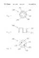
- FIG. 1is a top view of a weight stack plate and insert constructed according to the principles of the present invention
- FIG. 2is a top view of the weight stack plate of FIG. 1, the insert having been removed;
- FIG. 3is a sectioned side view of the weight stack plate of FIG. 2;
- FIG. 4is a top view of the insert of FIG. 1;
- FIG. 5is a side view of the insert of FIG. 1;
- FIG. 6is a bottom view of the insert of FIG. 1;
- FIG. 7is a top view of a weight stack weight identical in size and configuration to the weight stack plate and insert of FIG. 1;
- FIG. 8is a top view of the weight stack plate of FIG. 2 together with a second discrete insert
- FIG. 9is a top view of the weight stack plate of FIG. 2 together with a third discrete insert
- FIG. 10is a top view of the weight stack plate of FIG. 2 together with the insert of FIG. 1, but oriented differently;
- FIG. 11is a top view of the weight stack plate of FIG. 2 together with the insert of FIG. 8, but oriented differently;
- FIG. 12is a top view of a weight stack comprising the weight stack plates and inserts of FIGS. 1 and 8 - 11 , the plates having been stacked one on top of the other;
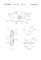
- FIG. 13is a fragmented front view of a selector rod constructed according to the principles of the present invention and suitable for use together with the weight stack of FIG. 12;
- FIG. 14is a sectioned front view of an upper portion of the selector rod of FIG. 13;
- FIG. 15is an enlarged front view of a catch on the selector rod of FIG. 13;
- FIG. 16is a top view of the selector rod of FIG. 13;
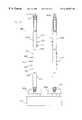
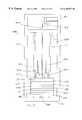
- FIG. 17is a front view of an exercise apparatus constructed according to the present invention and including the weight stack of FIG. 12 and the selector rod of FIG. 13;
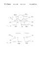
- FIG. 18is a top view of an adjustment assembly on the exercise apparatus of FIG. 17;
- FIG. 19is a top view of the weight of FIG. 2 together with a second type of insert constructed according to the present invention.
- FIG. 20is a top view of the weight of FIG. 2 together with a second discrete insert of the second type
- FIG. 21is a top view of the weight of FIG. 2 together with a third discrete insert of the second type
- FIG. 22is a top view of the weight of FIG. 2 together with a fourth discrete insert of the second type
- FIG. 23is a top view of the weight of FIG. 2 together with an insert similar to the insert of FIG. 11;
- FIG. 24is a top view of a weight stack comprising the weights and inserts of FIGS. 19-23, the weights having been stacked one on top of the other;
- FIG. 25is a top view of the weight of FIG. 2 together with a third type of insert constructed according to the present invention.
- FIG. 26is a top view of a weight stack including the weight and insert of FIG. 25 and ten additional weights and inserts stacked beneath the weight and insert of FIG. 25;
- FIG. 27is a top view of a weight of a different type together with two inserts of the third type
- FIG. 28is a front view of a pair of selector rods constructed according to the principles of the present invention and suitable for use together with the weight of FIG. 27;
- FIG. 29is a partially sectioned top view of a weight stack comprising yet another type of weight, with a selector rod in a first orientation relative to weights within the stack;
- FIG. 30is a partially sectioned top view of the weight stack of FIG. 29, with the selector rod occupying a second orientation relative to the weights within the stack;
- FIG. 31is a front view of the selector rod of FIG. 29;
- FIG. 32is partially sectioned front view of another weight stack exercise apparatus constructed according to the principles of the present invention.
- FIG. 33is a top view of a weight adjustment assembly and uppermost weight on the apparatus of FIG. 32;
- FIG. 34is a top view of another weight on the apparatus of FIG. 32;
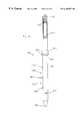
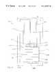
- FIG. 35is a fragmented front view of yet another weight stack exercise apparatus constructed according to the present invention.
- FIG. 36is a fragmented front view of still another weight stack exercise apparatus constructed according to the present invention.
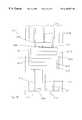
- FIG. 37is a fragmented front view of one more weight stack exercise apparatus constructed according to the present invention.
- the present inventionprovides methods and apparatus which facilitate the provision of selectively adjustable weight stack resistance to exercise motion.
- the present inventionallows a person to adjust weight stack resistance simply by rotating one or more selector rods relative to weights within the stack in order to select a desired amount of weight.
- a weight stack plate constructed according to the principles of the present inventionis designated as 100 in FIG. 1 .
- the weight stack plate 100includes a weight 101 and an attachment or insert 200 .
- the weight 101is shown by itself in FIGS. 2-3.
- the weight 101is generally rectangular in shape and is made from a relatively heavy and durable material, such as steel.
- Circular holes 103 and 104are formed through the weight 101 , proximate opposite ends thereof, to receive guide rods (designated as 713 and 714 in FIG. 17) in a manner known in the art.
- guide rodsare commonplace on most weight stacks, but also, that the present invention is not limited to such an arrangement.
- U.S. Pat. No. 5,374,229 to Sencilwhich is incorporated herein by reference to same.
- a relatively larger opening 102is formed through the center of the weight 101 to receive the insert 200 and accommodate a selector rod (designated as 610 in FIG. 13 ).
- the central opening 102is generally circular but includes radially extending slots 107 which are circumferentially spaced about the opening 102 .
- the opening 102is formed in part by a conical sidewall 105 which diverges away from the top of the weight 101 , and in part by a cylindrical sidewall 106 which meets the conical sidewall 105 within the weight 101 and continues through to the bottom of the weight 101 .
- the insert 200is shown by itself in FIGS. 4-6.
- the insert 200is generally conical in shape and is made from a relatively durable and conveniently molded material, such as plastic.
- the insert 205has a conical sidewall 205 which is sized and configured to concentrically nest within the conical sidewall 105 of the weight 101 .
- the sidewall 205extends between a top surface 208 and a bottom surface 209 .
- the sidewall 205bounds a central opening 202 which extends through the insert 200 .
- Diametrically opposed tabs 206extend radially inward from the sidewall 205 and cooperate with the sidewall 205 to define a keyway (for reasons discussed below).
- Fins 207extend radially outward from the sidewall 205 and are sized and configured to nest within the slots 107 in the weight 101 .
- the fins 207 and the slots 107cooperate to align the insert 200 relative to the weight 101 and to prevent rotation of the former relative to the latter.
- the orientation of each insertis significant, but also, that the present invention is not limited to this particular manner of construction.
- some additional insert attachment methodsare disclosed in U.S. Pat. No. 4,601,466 to Lais, which is incorporated herein by reference to same.
- FIGS. 7-11A set of weight stack plates is shown in FIGS. 7-11.
- the weight stack plate 100 ′ in FIG. 7is similar to that shown in FIG. 1, except that the keyway is formed in the plate itself, rather than by securing an insert to the plate 100 ′.
- the inclusion of FIG. 7is intended to emphasize that the present invention is not limited to either a specific combination of parts or a particular method of construction.
- a second weight stack plate 110is shown in FIG. 8 .
- the weight stack plate 110includes an identical weight 101 and a distinct insert 210 .
- the insert 210has structural features similar to those of the insert 200 , except for the relative orientations of the tabs 216 and the fins 207 (and the orientation of the resulting keyway).
- the tabs 216 and the tabs 206 (or 206 ′)occupy discrete sectors when the plate 110 is aligned with and stacked beneath the plate 100 (or 100 ′).
- the samemay be said for each of the weight stack plates 120 , 130 , and 140 and corresponding inserts 220 , 230 and 240 shown in FIGS. 9, 10 , and 11 , respectively.
- the tabs 206 , 216 , 226 , 236 , and 246 on the weight platesare disposed at discrete orientations (and within discrete sectors) relative to one another, and they leave diametrically opposed openings 255 unobstructed along the height of the stack.
- a selector rod 610 and portions thereofare shown in FIGS. 13-16.
- the rod 610extends between a first, lower end 611 and a second, upper end 612 .
- Gear teeth 613are disposed on the lower end 611 to provide a means for rotating the rod 610 .
- a cap 614is threaded onto the upper end 612 of the rod 610 and effectively seals off a compartment 615 .
- a shaft 632is disposed within the compartment 615 and connected to an end of a flexible cable or connector 630 . As is known in the art, an opposite end of the cable 630 is connected to a force receiving member which may be acted upon subject to resistance from the weight of the selector rod 610 and any weight stack plates engaged thereby.
- Depressions 633are formed in the shaft 632 proximate the upper end thereof to selectively receive a ball detent 640 mounted on the sidewall of the compartment 615 .
- the rod 610is rotatable relative to the shaft 632 and the cable 630 , and the ball detent 640 and holes 633 cooperate to bias the rod 610 toward discrete orientations (or sectors) relative to the shaft 632 and the cable 630 .
- These discrete orientations of the holes 533coincide with the orientations of the tabs 206 , 216 , 226 , 236 , and 246 on the respective weight stack plates 100 , 110 , 120 , 130 , and 140 .
- Selector pins 621 - 625extend radially outward from opposite sides of the rod 610 .
- Each of the pins 621 - 625is disposed immediately beneath, and within the cylindrical wall 106 of, a respective weight stack plate 100 , 110 , 120 , 130 , or 140 .
- each of the pins 621 - 625includes a main beam 691 with an upwardly extending nub 693 on a distal end thereof.
- the pins 621 - 625may be rotated into alignment with any one of the pairs of weight plate tabs 206 , 216 , 226 , 236 , or 246 or the unobstructed openings 255 . If the pins 621 - 625 are aligned with the openings 255 , then none of the weight stack plates 100 , 110 , 120 , 130 , or 140 will be carried upward by the selector rod 610 , and exercise (pulling on the cable 630 ) may be performed subject only to the weight of the selector rod 610 .
- a top plateis typically rigidly secured to the selector rod to keep the selector rod aligned with the stack under all circumstances of operation (including the situation where no selector pin is inserted). Such a top plate may be added to the present invention to move up and down with the selector rod but nonetheless allow rotation of the selector rod relative to the stack. With the addition of a top plate, the minimal resistance setting will include the weight of such a top plate, as well.
- the pins 621 - 625are aligned with the tabs 206 on the first weight stack plate 100 , then exercise may be performed subject to the weight of the selector rod 610 and the uppermost weight stack plate 100 .
- the main beams 691 of the pins 621engage first recesses 291 in the underside of the tabs 206 , and the nubs 693 move through grooves 292 and into second recesses 293 (see FIG. 6 ).
- the recesses 291cooperate with the main beams 691 to bias the weight stack plate 100 against rotation relative to the selector rod 610 during exercise movement.
- the recesses 293cooperate with the nubs to discourage both rotation and radial movement of the weight stack plate 100 relative to the selector rod 610 during exercise movement.
- the weight stack plates 100 , 110 , 120 , 130 , and 140 and the selector rod 610are shown on an exercise apparatus 700 in FIG. 17 .
- the exercise apparatus 700includes a frame 710 having an upper end 711 and a lower end 712 , with guide members or rods 713 and 714 extending vertically therebetween.
- the guide rods 713 and 714extend through the holes 103 and 104 , respectively, in the weights 101 and help to maintain alignment of the weight stack plates 100 , 110 , 120 , 130 , and 140 relative to one another.
- the cable 630extends upward from the connector rod 610 to a pulley 716 which routes the cable 630 toward a force receiving member of any type known in the art.
- a unitary protective shield 750may be secured across the entire side of the frame 710 and function as a partition between the stack of weights and any objects and/or people in the vicinity of the apparatus 700 .
- An opaque shieldmay used to the extent that it is considered advantageous to hide the amount of weight being lifted.
- the lower end 611 of the rod 610engages a gear assembly 730 in the absence of a threshold amount of tension in the cable 630 .
- the gear assembly 730cooperates with the gear teeth 613 on the rod 610 to provide a means for rotating the rod 610 relative to the weight stack plates 100 , 110 , 120 , 130 , and 140 .
- three idler gears 741 - 743are arranged in an equilateral triangle formation suitable for receiving the lower end 611 of the rod 600 in the center thereof.
- Each of the idler gears 741 - 743is provided with gear teeth 746 which mate with the gear teeth 613 on the rod 610 .
- a knob 731Positioned adjacent the idler gear 741 is a knob 731 which has teeth that mate with the gear teeth 746 on the idler gear 741 .
- rotation of the knob 731causes rotation of the rod 610 .
- Markings 732 on the knob 731cooperate with a pointer 733 on the frame 710 to indicate the orientation of the pins 621 - 625 relative to the tabs 206 , 216 , 226 , 236 , and 246 , and thereby indicate the amount of weight selected.
- weight stack plates 300 , 310 , 320 , 330 , and 340include the same weight 101 as the previous embodiment, but a different set of inserts.
- the alternative inserts 350 , 360 , 370 , 380 , and 390are provided with respective tabs 351 , 361 , 371 , 381 , and 391 , which are engaged by respective pins 621 - 625 whenever a relatively lower weight stack plate is engaged.
- the pins 621underlie the tabs 351
- the pins 622underlie the tabs 361
- the pins 623underlie the tabs 371
- the pins 624remain clear of the tabs 381
- the pins 625remain clear of the tabs 391 .
- FIGS. 25-26Yet another, discrete type of weight stack plate is shown in FIGS. 25-26.
- These weight stack plateslikewise include the same weight 101 as the previous embodiments and another different set of inserts.
- the alternative insertsone of which is designated as 410 , are provided with respective tabs 416 , 426 , 436 , 446 , 456 , 466 , 476 , 486 , 496 , 506 , and 516 , (as well as fins 447 , for example) and are intended for use with a selector rod having only a single, radially extending selector pin at each discrete elevation.
- This particular embodimentgains the advantage of accommodating additional weight stack plates, but at the expense of engaging each plate in only a single sector (as opposed to diametrically opposed sectors).
- the relatively higher inserts in this embodimentmay be modified to function like those shown in FIGS. 19-24, so that the load from multiple weight stack plates is distributed among respective pins.
- FIG. 27Still another, discrete type of weight stack plate is shown in FIG. 27 .
- These weight stack platestwo of which are designated as 561 and 571 , require a different type of weight, but inserts similar to those shown in FIG. 25 .
- the weightitself has two relatively larger openings 562 a and 562 b, in addition to two guide rod holes 563 and 564 .
- Each of the larger openings 562 a and 562 bis configured similar to the opening 102 shown in FIGS. 2-3.
- all of the inserts 410are identical to that shown in FIG. 25, and all are inserted into their respective weights at the same orientation shown in FIG. 27 .
- all of the tabs 416 within a respective column of insertsare aligned with one another (or occupy a single sector).
- the selector assembly for this embodimentis designated as 800 in FIG. 28 .
- the selector assembly 800includes two selector rods 810 a and 810 b which are rotated in opposite directions by a motorized gear box 808 (in response to signals generated by a controller, for example).
- a controllerfor example
- Examples of automatic and/or remotely controlled weight selectionare disclosed in U.S. Pat. No. 5,037,089 to Spagnuolo et al. and U.S. Pat. No. 4,546,971 to Raasoch, which are incorporated herein by reference to same.
- Each selector rod 810 a and 810 bhas threads 813 on its lower end which interengage with respective gears 809 a and 809 b on the motorized gear box 808 .
- Each selector rod 810 a and 810 bhas an upper end 812 similar to that on the selector rod 610 shown in FIGS. 13-14.
- the cables 838 a and 838 bextend upward and are connected to respective pulleys which, in turn, are keyed to a common shaft. An additional cable is connected to a separate pulley on the shaft and then routed to an exercise member.
- Each selector rod 810 a and 810 balso has pins 821 - 831 extending radially outward into discrete sectors about a respective rod. Rotation of the rods 810 a and 810 b brings opposing pairs of pins 821 - 831 into alignment with the tabs 416 on successively lower (or higher) weight stack plates.
- This embodimentmay be seen to be advantageous because the selected weight stack is supported at two discrete locations, despite the accommodation of a greater number of weight stack plates.
- Another embodiment of the present invention(not shown fully assembled) combines the foregoing cable and pulley arrangement with each of two discrete weight stacks configured to require only a single selector rod.
- a first cableextends upward from a first selector rod to a first pulley
- a second cableextends upward from a second selector rod to a second pulley.
- the first selector rodinserts through seven weight stack plates weighing five pounds and disposed in a first stack
- the second selector rodinserts through seven weight stack plates weighing forty pounds and disposed in a second stack.
- the amount of resistancecan be varied in five pound increments from five pounds to three hundred and fifteen pounds.
- Another variationis to rotatably mount the two selector rods on a single carriage, which in turn, is suspended from a single cable that extends all the way to the exercise member.
- a weight stack plate 900includes a weight 901 without any insert.
- the weight 901is generally rectangular in shape and is made from a relatively heavy and durable material, such as steel.
- Circular holes 903 and 904are formed through the weight 901 , proximate opposite ends thereof, to receive guide members or rods in a manner known in the art.
- a relatively larger opening 902is formed through the center of the weight 901 to accommodate a selector rod (designated as 910 in FIG. 31 ).
- the central opening 902is generally semi-circular, defining a sector of somewhat more than 180 degrees, and it extends straight down through the weight 901 .
- a generally H-shaped depression 909is formed in the top of the weight 901 to accommodate a generally H-shaped spacer 999 which is made of rubber (or other suitable shock-absorbing material).
- the selector rod 910extends between a first, lower end 911 and a second, upper end 912 .
- the upper end 912is similar to that on the selector rod 610 , and it accommodates a shaft 932 having slots 933 formed therein, proximate the upper end thereof.
- the slots 933similarly cooperate with a ball detent to bias the rod 910 toward discrete orientations, while also allowing for slight axial movement of the rod 910 relative thereto.
- the lower end 911is generally pointed but lacks the gear teeth of the selector rod 610 .
- Selector pins 921 - 927extend radially outward from the selector rod 910 in discrete sectors disposed about the rod. Each of the pins 921 - 927 is disposed immediately beneath a respective weight stack plate, like the one designated as 900 .
- the rod 910may occupy an orientation wherein all of the pins 921 - 927 are free of the weight stack plates, in which case exercise may be performed subject only to the weight of the selector rod 910 (and any top plate).
- the rod 910may be rotated, by hand for example, to an orientation wherein the pin 921 underlies the uppermost weight stack plate.
- the selector rod 910may be rotated further to place additional pins 922 - 927 under successively lower plates.
- locking pins 942extend radially outward from the selector rod 910 at diametrically opposed locations.
- a collar 944is rotatably mounted on the selector rod 910 , with the locking pins 942 extending through respective slots 946 in the collar 944 .
- the lower end of the collar 944occupies a position adjacent the uppermost weight stack plate, and the slots 946 extend at an angle relative thereto. Once the desired number of weight stack plates has been selected, the collar 944 may be rotated to clamp the selected weights together.
- the stability of the selected weightsis further enhanced by providing ridges and/or recesses in the underside of the weight stack plates to selectively engage the selector pins 921 - 927 and discourage rotation of the latter relative to the former except when the collar 944 is loosened.
- Another optionis to provide angled bearing surfaces on the pins 921 - 927 which will tend to push upward on respective weight stack plates upon rotation into engagement therewith.
- Yet another variation of the present inventionis to eliminate the central opening through each weight stack plate and dispose the selector rod(s) outside the planform of the plates. Pins on the rod(s) may be selectively rotated beneath respective plates to engage same.
- the present inventionis not limited to selector rods which insert through the plates in a weight stack.
- the exercise apparatus 1000includes a frame 1010 having an upper end 1011 and a lower end 1012 , with guide members or rods 1013 and 1014 extending vertically therebetween.
- the guide rods 1013 and 1014extend through holes 1103 and 1104 (see FIGS. 33 - 34 ), respectively, in each of the weight stack plates 1100 , 1110 , 1120 , 1130 , 1140 , 1150 , 1160 , 1170 , 1180 , and 1190 to maintain alignment of the weight stack.
- a fastener 1102extends upward from the uppermost weight 1100
- a cable 1030extends upward from the fastener 1102 .
- the cable 1030is routed about a pulley 1016 and proceeds to a force receiving member of any type known in the art.
- a shock-absorbing bumper 1060is disposed beneath the weight stack to absorb impact from descending weights.
- a unitary protective shield 1050may be secured across the entire side of the frame 1010 and function as a partition and/or shroud between the stack of weights and any people in the vicinity of the apparatus 1000 .
- a motor driven roller 1062is rotatably mounted on the uppermost weight stack plate 1100 together with rollers 1063 and 1064 .
- Threaded holes 1068 and 1069are formed through respective rollers 1063 and 1064 to mate with exterior threads on respective shafts 1078 and 1079 .
- threaded holes 1108 and 1109are formed through each of the weights 1101 to likewise receive respective shafts 1078 and 1079 .
- Rotation of the motor driven roller 1062causes rotation of the rollers 1063 and 1064 , thereby moving the shafts 1078 and 1079 downward or upward, into or out of engagement with the threaded holes 1108 and 1109 in any number of weight stack plates.
- Interengaging gear teethmay be provided at the interfaces between the rollers 1063 and 1064 and the motor driven roller 1062 to facilitate rotational transmission therebetween.
- FIG. 35shows a weight stack exercise apparatus 1200 which combines aspects of the previous embodiment 1000 and the weight stack shown in FIG. 24.
- a weight stack 1202is supported by a pair of guide rods 1213 and 1214 which extend between an upper frame portion 1211 and a lower frame portion 1212 .
- a shock absorbing bumper 1206is disposed between the weight stack 1202 and the lower frame portion 1212 .
- a bracket 1220is secured to the uppermost weight stack plate 1241 , and an end of a flexible connector 1230 is secured to the bracket 1220 .
- An opposite end of the connector 1230is connected to a force receiving member (not shown).
- a selector rod 1260is rotatably mounted to the uppermost weight stack plate 1241 .
- the selector rod 1260selectively engages the weights 1241 - 1246 in the stack 1202 in much the same manner as the selector rod 610 cooperates with the weight stack shown in FIG. 24.
- a shaft 1226is rigidly secured to the bracket 1220 and extends downward into the selector rod 1260 to keep the latter in alignment with the weight stack 1202 .
- a plate 1265is rigidly secured to the selector rod 1260 to transmit the weight of the rod 1260 and any engaged lower weights 1242 - 1246 to the uppermost weight 1241 .
- FIG. 36shows an exercise apparatus 1300 similar in many respects to the foregoing embodiment 1200 , as suggested by the common reference numerals.
- a pair of shock absorbing bumpers 1306 and 1307are substituted for the shock absorbing bumper 1206
- a frame mounted shaft 1316is provided to keep the selector rod 1360 in alignment with the weight stack 1202 .
- the shaft 1316preferably includes spring-biased, telescoping sections to accommodate upward travel of the weights 1241 - 1246 over a distance greater than the height of the stack 1202 .
- FIG. 37shows an exercise apparatus 1400 similar in some respects to the foregoing embodiments 1200 and 1300 , as suggested by the common reference numerals.
- a stack of different weights 1441 - 1446has been substituted for the weight stack 1202 .
- each of the weights 1441 - 1445has its own centrally mounted selector rod 1460 which is selectively rotatable into and out of engagement with its counterpart on an underlying weight stack plate.
- each selector rod 1460has an upper portion and a lower portion, and the former is sized and configured to receive the latter.
- the lower portion of the selector rod 1460 on the third highest plate 1443protrudes downward beneath the plate 1443 and into engagement with an upper portion of the selector rod on the fourth highest plate 1444 .
- a knob 1465is secured to the upper portion of the selector rod 1460 on the uppermost plate 1441 to facilitate selection of the desired number of plates. Rotation of the knob 1465 a first amount in a first direction causes the uppermost selector rod 1460 to engage the second highest selector rod 1460 . Rotation of the knob 1465 an additional amount in the first direction causes the next highest selector rod 1460 to engage the third highest selector rod 1460 , and so on. Rotation of the knob 1465 as far as allowed in a second, opposite direction ensures that all of the selector rods 1460 are disengaged from one another. The likelihood of engaging a relatively lower weight prematurely may be reduced by impeding rotation of the selector rods 1460 .
- a further variation of the present inventionis to “fish” for the desired number of weight stack plates by moving the selector rod up or down and then rotating into engagement with the desired weight.
- the present inventionmay also be described in terms of a method of providing adjustable resistance to exercise, involving the arrangement of a plurality of weights into a stack; and the rotation of a selector rod relative to the stack to engage a desired weight within the stack.
- This methodmay further involve providing holes through the weights to receive the selector rod; having the selector rod occupy all such holes during rotation, regardless of which weight is the desired weight; rotating the selector rod a fraction of a revolution to engage an additional weight; threading the selector rod into engagement with the desired weight; compressing the desired weight against an uppermost weight and any intermediate weights; rotating the selector rod about its longitudinal axis until a radially extending pin underlies a portion of the desired weight; and/or having the selector rod engage any weight disposed above the desired weight, as well as the desired weight itself.
- the present inventionmay also be described in terms of a method of adjusting resistance to exercise, involving the arrangement of a plurality of weights into a stack; the rotation of a selector rod a first amount relative to the stack to engage a first weight within the stack; and rotation of the selector rod a second amount relative to the stack to engage a second weight within the stack.
- This methodmay further involve threading the selector rod into each weight to be engaged; clamping all the engaged weights together; rotating a selector rod in the first weight the second amount to engage a selector rod on the second weight; rotating the selector rod about its longitudinal axis until a radially extending pin underlies a portion of the second weight; and/or having the selector rod separately engage the first weight and the second weight.
Landscapes
- Health & Medical Sciences (AREA)
- Life Sciences & Earth Sciences (AREA)
- Biophysics (AREA)
- Orthopedic Medicine & Surgery (AREA)
- General Health & Medical Sciences (AREA)
- Physical Education & Sports Medicine (AREA)
- Rehabilitation Tools (AREA)
Abstract
Description
Claims (27)
Priority Applications (2)
| Application Number | Priority Date | Filing Date | Title |
|---|---|---|---|
| US09/259,732US6186927B1 (en) | 1996-07-19 | 1999-03-01 | Weight selection apparatus |
| US09/300,546US6422979B1 (en) | 1996-07-19 | 1999-04-27 | Weight selection methods for adjusting resistance to exercise |
Applications Claiming Priority (3)
| Application Number | Priority Date | Filing Date | Title |
|---|---|---|---|
| US2219696P | 1996-07-19 | 1996-07-19 | |
| US08/886,607US5876313A (en) | 1996-07-19 | 1997-07-01 | Weight stack methods and apparatus |
| US09/259,732US6186927B1 (en) | 1996-07-19 | 1999-03-01 | Weight selection apparatus |
Related Parent Applications (1)
| Application Number | Title | Priority Date | Filing Date |
|---|---|---|---|
| US08/886,607ContinuationUS5876313A (en) | 1996-07-19 | 1997-07-01 | Weight stack methods and apparatus |
Related Child Applications (1)
| Application Number | Title | Priority Date | Filing Date |
|---|---|---|---|
| US09/300,546Continuation-In-PartUS6422979B1 (en) | 1996-07-19 | 1999-04-27 | Weight selection methods for adjusting resistance to exercise |
Publications (1)
| Publication Number | Publication Date |
|---|---|
| US6186927B1true US6186927B1 (en) | 2001-02-13 |
Family
ID=26695658
Family Applications (2)
| Application Number | Title | Priority Date | Filing Date |
|---|---|---|---|
| US08/886,607Expired - LifetimeUS5876313A (en) | 1996-07-19 | 1997-07-01 | Weight stack methods and apparatus |
| US09/259,732Expired - LifetimeUS6186927B1 (en) | 1996-07-19 | 1999-03-01 | Weight selection apparatus |
Family Applications Before (1)
| Application Number | Title | Priority Date | Filing Date |
|---|---|---|---|
| US08/886,607Expired - LifetimeUS5876313A (en) | 1996-07-19 | 1997-07-01 | Weight stack methods and apparatus |
Country Status (1)
| Country | Link |
|---|---|
| US (2) | US5876313A (en) |
Cited By (57)
| Publication number | Priority date | Publication date | Assignee | Title |
|---|---|---|---|---|
| US20020077230A1 (en)* | 2000-03-10 | 2002-06-20 | Lull Andrew P. | Adjustable-load unitary multi-position bench exercise unit |
| US20040005968A1 (en)* | 2002-06-07 | 2004-01-08 | Nautilus, Inc. | Adjustable dumbbell system |
| US20040023762A1 (en)* | 2002-07-01 | 2004-02-05 | Lull Andrew P. | Leg press and abdominal crunch exercise machine |
| US20040220025A1 (en)* | 1997-09-29 | 2004-11-04 | Krull Mark A. | Exercise resistance methods and apparatus |
| US20050176559A1 (en)* | 2004-02-10 | 2005-08-11 | Kenneth Carter | Therapy weight system |
| USD508628S1 (en) | 2002-07-31 | 2005-08-23 | Nautilus, Inc. | Adjustable dumbbell support base |
| US7077790B1 (en) | 2002-01-31 | 2006-07-18 | Krull Mark A | Adjustable weight exercise methods and apparatus |
| US7077791B2 (en) | 2002-04-18 | 2006-07-18 | Mautilus, Inc. | Weight selection methods and apparatus |
| US7083554B1 (en) | 1997-02-27 | 2006-08-01 | Nautilus, Inc. | Exercise machine with infinite position range limiter and automatic belt tensioning system |
| US20060189458A1 (en)* | 2005-01-27 | 2006-08-24 | D.K.B. Group, Llc | Weight-training apparatus having selectable weight plates |
| USD528173S1 (en) | 2003-06-05 | 2006-09-12 | Nautilus, Inc. | Adjustable dumbbell base |
| US7108641B2 (en) | 2000-05-03 | 2006-09-19 | Nautilus, Inc. | Exercise equipment with multi-positioning handles |
| USD528611S1 (en) | 2004-08-16 | 2006-09-19 | Nautilus, Inc. | Adjustable dumbbell |
| US20060217245A1 (en)* | 2005-03-17 | 2006-09-28 | Nautilus, Inc. | Weight selection apparatus for a weight stack |
| US7115080B2 (en) | 2002-08-01 | 2006-10-03 | Nautilus, Inc. | Collapsible seat for combination hack squat and leg press machine |
| USD540405S1 (en) | 2002-07-31 | 2007-04-10 | Nautilus, Inc. | Adjustable dumbbell |
| USD540894S1 (en) | 2002-08-01 | 2007-04-17 | Nautilus, Inc. | Adjustable dumbbell |
| US20080242520A1 (en)* | 2007-03-28 | 2008-10-02 | Hubbard Adam P | Exercise apparatus, resistance selector for exercise apparatus and related methods |
| US20090023561A1 (en)* | 2007-07-20 | 2009-01-22 | Exersmart, Llc | Resistance system for fitness equipment |
| US7540832B2 (en) | 2004-12-14 | 2009-06-02 | Nautilus, Inc. | Exercise weight stack methods and apparatus |
| US20090149301A1 (en)* | 2007-12-07 | 2009-06-11 | Johnson Health Tech Co., Ltd. | Resistance exercise apparatus |
| US20090163333A1 (en)* | 2007-12-20 | 2009-06-25 | Precor Incorporated | Weight stack selector |
| US20090163334A1 (en)* | 2007-12-20 | 2009-06-25 | Precor Incorporated | Incremental weight and selector |
| US20090163332A1 (en)* | 2007-12-20 | 2009-06-25 | Precor Incorporated | Weight stack selector |
| US20090186748A1 (en)* | 2008-01-23 | 2009-07-23 | Nautilus, Inc. | Adjustable dumbbell with an orientation feature |
| US20090227432A1 (en)* | 2008-03-05 | 2009-09-10 | Icon Health & Fitness, Inc. | Exercise apparatus, resistance selector for exercise apparatus and related methods |
| US7662074B2 (en) | 2004-10-04 | 2010-02-16 | Nautilus, Inc. | Exercise machine having rotatable weight selection index |
| US20100120588A1 (en)* | 2008-11-07 | 2010-05-13 | Krull Mark A | Adjustable weight kettlebell |
| US20100311550A1 (en)* | 2004-10-04 | 2010-12-09 | Nautilus, Inc. | Exercise machine having rotatable weight selection index |
| US20110045956A1 (en)* | 2009-07-31 | 2011-02-24 | Matthew Colledge | Weightlifting device with mechanism for disengaging weight plates |
| US8137248B1 (en)* | 1997-09-29 | 2012-03-20 | Krull Mark A | Exercise resistance apparatus |
| US8568279B2 (en) | 2010-03-31 | 2013-10-29 | Nautilus, Inc. | Engagement interface for an exercise machine |
| US8771153B2 (en) | 2010-11-08 | 2014-07-08 | Icon Ip, Inc. | Exercise weight bar with rotating handle and cam selection device |
| US8845498B2 (en) | 2010-03-31 | 2014-09-30 | Nautilus, Inc. | Lockout mechanism for a weight stack exercise machine |
| US8876674B2 (en) | 2010-03-31 | 2014-11-04 | Nautilus, Inc. | Selectable weight stack |
| US9186537B2 (en) | 2013-01-03 | 2015-11-17 | Precor Incorporated | Incremental weight and selector |
| USD745939S1 (en) | 2013-03-15 | 2015-12-22 | Arqex Outdoor Fitness Systems, Llc | Strength training and stretching machine with adjustable arms |
| USD753246S1 (en) | 2013-03-15 | 2016-04-05 | Arqex Outdoor Fitness Systems, Llc | Strength training and stretching machine |
| US9314658B2 (en) | 2013-03-15 | 2016-04-19 | Arqex Outdoor Fitness Systems, Llc | Strength training and stretching system |
| US9555280B2 (en) | 2013-03-15 | 2017-01-31 | Arqex Outdoor Fitness Systems, Llc | Attachment assembly for an exercise device and an exercise device incorporating the same |
| USD777850S1 (en) | 2015-01-16 | 2017-01-31 | Arqex Outdoor Fitness Systems, Llc | Variable resistance band |
| US9555278B2 (en) | 2013-03-15 | 2017-01-31 | Arqfx Outdoor Fitness Systems, Llc | Strength training and stretching system and resistance band assembly for use therewith |
| US9630048B2 (en) | 2013-03-15 | 2017-04-25 | Arqex Outdoor Fitness Systems, Llc | Variable resistance band assembly and method of using the same |
| US9682267B2 (en) | 2013-03-15 | 2017-06-20 | Arqex Outdoor Fitness Systems, Llc | Insert for use with a resistance band assembly and a method of using the same |
| US9724553B2 (en) | 2013-03-15 | 2017-08-08 | Arqex Outdoor Fitness Systems, Llc | Resistance band assembly and a method of varying a resistive force applied thereby |
| US20180104525A1 (en)* | 2016-10-13 | 2018-04-19 | Salvatore Naimo | Weight Selecting Mechanism for Exercise Equipment |
| US10188890B2 (en) | 2013-12-26 | 2019-01-29 | Icon Health & Fitness, Inc. | Magnetic resistance mechanism in a cable machine |
| US10252109B2 (en) | 2016-05-13 | 2019-04-09 | Icon Health & Fitness, Inc. | Weight platform treadmill |
| US10279212B2 (en) | 2013-03-14 | 2019-05-07 | Icon Health & Fitness, Inc. | Strength training apparatus with flywheel and related methods |
| US10293211B2 (en) | 2016-03-18 | 2019-05-21 | Icon Health & Fitness, Inc. | Coordinated weight selection |
| US10426989B2 (en) | 2014-06-09 | 2019-10-01 | Icon Health & Fitness, Inc. | Cable system incorporated into a treadmill |
| US10441840B2 (en) | 2016-03-18 | 2019-10-15 | Icon Health & Fitness, Inc. | Collapsible strength exercise machine |
| US10449416B2 (en) | 2015-08-26 | 2019-10-22 | Icon Health & Fitness, Inc. | Strength exercise mechanisms |
| US10463906B2 (en) | 2018-02-02 | 2019-11-05 | Jaxamo Ltd. | Exercise devices, systems, and methods |
| US10661114B2 (en) | 2016-11-01 | 2020-05-26 | Icon Health & Fitness, Inc. | Body weight lift mechanism on treadmill |
| US10940360B2 (en) | 2015-08-26 | 2021-03-09 | Icon Health & Fitness, Inc. | Strength exercise mechanisms |
| USD1022081S1 (en) | 2023-05-22 | 2024-04-09 | Dane Hoover | Exercise bench |
Families Citing this family (22)
| Publication number | Priority date | Publication date | Assignee | Title |
|---|---|---|---|---|
| US5876313A (en)* | 1996-07-19 | 1999-03-02 | Krull; Mark A. | Weight stack methods and apparatus |
| US6422979B1 (en)* | 1996-07-19 | 2002-07-23 | Mark A. Krull | Weight selection methods for adjusting resistance to exercise |
| US6540650B1 (en)* | 1999-05-26 | 2003-04-01 | Mark A. Krull | Weight selection method and apparatus |
| US6117049A (en)* | 1999-10-13 | 2000-09-12 | Lowe; John C. | Exercise equipment weight selector |
| US7335139B2 (en)* | 2001-11-13 | 2008-02-26 | Cybex International, Inc. | Incremental weight system |
| US7025713B2 (en)* | 2003-10-13 | 2006-04-11 | Icon Ip, Inc. | Weight lifting system with internal cam mechanism |
| US20050132803A1 (en)* | 2003-12-23 | 2005-06-23 | Baldwin David J. | Low cost integrated MEMS hybrid |
| US7413532B1 (en)* | 2004-04-23 | 2008-08-19 | Brunswick Corporation | Exercise apparatus with incremental weight stack |
| US7137932B2 (en)* | 2004-12-13 | 2006-11-21 | Doudiet Adam T | Dumbbell adjusting system |
| US7537550B1 (en)* | 2004-12-14 | 2009-05-26 | Krull Mark A | Exercise weight stack methods and apparatus |
| US7291098B1 (en)* | 2005-05-03 | 2007-11-06 | Krull Mark A | Exercise dumbbell methods and apparatus |
| US7578772B2 (en)* | 2006-01-09 | 2009-08-25 | Stamina Products, Inc. | Adjustable weight |
| US7413533B2 (en)* | 2006-02-08 | 2008-08-19 | Asai Regent Limited | Adjustable dumbbell |
| US7604577B2 (en)* | 2006-02-08 | 2009-10-20 | Asia Regent Limited | Adjustable dumbbell and method |
| US7981012B1 (en)* | 2006-06-30 | 2011-07-19 | Krull Mark A | Exercise weight selection methods and apparatus |
| US7429235B2 (en)* | 2006-09-13 | 2008-09-30 | Stamina Products, Inc. | Dumbbell |
| US7597653B1 (en)* | 2007-08-07 | 2009-10-06 | Brunswick Corporation | Exercise apparatus with resistance selection |
| US8033965B1 (en)* | 2009-03-18 | 2011-10-11 | Krull Mark A | Adjustable weight kettlebell apparatus |
| US9192800B1 (en)* | 2012-12-18 | 2015-11-24 | Brunswick Corporation | Exercise equipment having a weight stack, connectors for exercise equipment having a weight stack and methods of assembling exercise equipment having a weight stack |
| US9682269B2 (en) | 2013-01-10 | 2017-06-20 | Automatic Weightstack I Jönköping Kommanditbolag | Weight lifting arrangement and weight selector apparatus for a weight lifting arrangement |
| US9604090B1 (en) | 2014-09-16 | 2017-03-28 | Brunswick Corporation | Weight stack assemblies for exercise apparatuses |
| CN107773908B (en)* | 2017-11-21 | 2024-04-30 | 深圳市汇泰科电子有限公司 | Kettle bell |
Citations (14)
| Publication number | Priority date | Publication date | Assignee | Title |
|---|---|---|---|---|
| US3647209A (en)* | 1970-05-15 | 1972-03-07 | Jack La Lanne | Weight lifting type exercising device |
| USRE31113E (en)* | 1977-02-10 | 1982-12-28 | Variable resistance lifting mechanism | |
| US4540171A (en)* | 1982-06-16 | 1985-09-10 | Clark Charles G | Variable resistance exercise apparatus |
| US4568078A (en)* | 1983-08-18 | 1986-02-04 | Weiss Ralph N | Weighted leg exerciser |
| EP0177643A1 (en)* | 1984-10-09 | 1986-04-16 | Géraud Vitrac | Device with precise, silent and quick latching for selecting and damping dynamic efforts, especially designed for muscle strengthening and reeducation apparatuses |
| US4624457A (en)* | 1981-02-04 | 1986-11-25 | Diversified Products Corporation | Portable wall mounted exercise unit |
| US4730828A (en)* | 1987-01-12 | 1988-03-15 | American Sports International, Ltd. | Body strength and conditioning frame structure |
| FR2613237A1 (en)* | 1987-03-30 | 1988-10-07 | Louvet Andre | Selector of conventional discs for muscle-development apparatuses |
| US4878662A (en)* | 1989-01-24 | 1989-11-07 | Chern Lu Meng | Exercise machine weight guide |
| US5221244A (en)* | 1991-03-20 | 1993-06-22 | Doss Steven G | Bar bell |
| US5306221A (en)* | 1992-12-15 | 1994-04-26 | Abe Itaru | Weight adjusting device for muscle training machine |
| US5669861A (en)* | 1996-04-18 | 1997-09-23 | Toups; Lanny J. | Incline resistance weight unit for exercise machine |
| US5839997A (en)* | 1998-01-22 | 1998-11-24 | Premise Group Llc | Weight-lifting apparatus and method |
| US5876313A (en)* | 1996-07-19 | 1999-03-02 | Krull; Mark A. | Weight stack methods and apparatus |
Family Cites Families (16)
| Publication number | Priority date | Publication date | Assignee | Title |
|---|---|---|---|---|
| US772906A (en)* | 1904-02-24 | 1904-10-18 | Spalding Mfg Company | Weight for chest-machines. |
| US848272A (en)* | 1905-06-30 | 1907-03-26 | Albert J Thornley | Exercising-machine. |
| US1053109A (en)* | 1910-12-08 | 1913-02-11 | Internat Gymnasium Supply Company | Wall exercising apparatus. |
| US3912261A (en)* | 1973-07-12 | 1975-10-14 | Sr Lloyd J Lambert | Exercise machine |
| US4411424A (en)* | 1982-02-08 | 1983-10-25 | Barnett Robert V | Weight lifting exercise apparatus |
| CA1206177A (en)* | 1983-01-06 | 1986-06-17 | Edgar H. Lais | Exercise weight |
| US5037089A (en)* | 1983-03-28 | 1991-08-06 | Patrick Spagnuolo | Exercise device having variable resistance capability |
| US4546971A (en)* | 1984-09-05 | 1985-10-15 | Paul Raasoch | Exercise device |
| SU1258447A1 (en)* | 1985-03-26 | 1986-09-23 | Белорусский Ордена Трудового Красного Знамени Политехнический Институт | Apparatus for developing the leg muscle force |
| SU1389789A2 (en)* | 1986-11-20 | 1988-04-23 | Белорусский Политехнический Институт | Arrangement for developing the strength of leg muscles |
| US4900018A (en)* | 1987-09-16 | 1990-02-13 | Ish Iii Arthur B | Exercise machine with multiple exercise stations |
| US4809973A (en)* | 1988-04-15 | 1989-03-07 | Nautilus Sports Medical Industries, Inc. | Weight training machine safety shield |
| US4878663A (en)* | 1988-11-08 | 1989-11-07 | Innovative Therapeutic Designs, Inc. | Direct drive rehabilitation and fitness apparatus and method of construction |
| US5263915A (en)* | 1989-08-30 | 1993-11-23 | Pacific Fitness Corporation | Exercise method with adjustable position exercise members |
| US5000446A (en)* | 1990-09-26 | 1991-03-19 | Sarno Timothy N | Color-coded weight stack pin system for exercise machines |
| US5374229A (en)* | 1993-05-04 | 1994-12-20 | Medx Corporation | Weight stack with alignment sleeve |
- 1997
- 1997-07-01USUS08/886,607patent/US5876313A/ennot_activeExpired - Lifetime
- 1999
- 1999-03-01USUS09/259,732patent/US6186927B1/ennot_activeExpired - Lifetime
Patent Citations (14)
| Publication number | Priority date | Publication date | Assignee | Title |
|---|---|---|---|---|
| US3647209A (en)* | 1970-05-15 | 1972-03-07 | Jack La Lanne | Weight lifting type exercising device |
| USRE31113E (en)* | 1977-02-10 | 1982-12-28 | Variable resistance lifting mechanism | |
| US4624457A (en)* | 1981-02-04 | 1986-11-25 | Diversified Products Corporation | Portable wall mounted exercise unit |
| US4540171A (en)* | 1982-06-16 | 1985-09-10 | Clark Charles G | Variable resistance exercise apparatus |
| US4568078A (en)* | 1983-08-18 | 1986-02-04 | Weiss Ralph N | Weighted leg exerciser |
| EP0177643A1 (en)* | 1984-10-09 | 1986-04-16 | Géraud Vitrac | Device with precise, silent and quick latching for selecting and damping dynamic efforts, especially designed for muscle strengthening and reeducation apparatuses |
| US4730828A (en)* | 1987-01-12 | 1988-03-15 | American Sports International, Ltd. | Body strength and conditioning frame structure |
| FR2613237A1 (en)* | 1987-03-30 | 1988-10-07 | Louvet Andre | Selector of conventional discs for muscle-development apparatuses |
| US4878662A (en)* | 1989-01-24 | 1989-11-07 | Chern Lu Meng | Exercise machine weight guide |
| US5221244A (en)* | 1991-03-20 | 1993-06-22 | Doss Steven G | Bar bell |
| US5306221A (en)* | 1992-12-15 | 1994-04-26 | Abe Itaru | Weight adjusting device for muscle training machine |
| US5669861A (en)* | 1996-04-18 | 1997-09-23 | Toups; Lanny J. | Incline resistance weight unit for exercise machine |
| US5876313A (en)* | 1996-07-19 | 1999-03-02 | Krull; Mark A. | Weight stack methods and apparatus |
| US5839997A (en)* | 1998-01-22 | 1998-11-24 | Premise Group Llc | Weight-lifting apparatus and method |
Cited By (90)
| Publication number | Priority date | Publication date | Assignee | Title |
|---|---|---|---|---|
| US7083554B1 (en) | 1997-02-27 | 2006-08-01 | Nautilus, Inc. | Exercise machine with infinite position range limiter and automatic belt tensioning system |
| US6974405B2 (en)* | 1997-09-29 | 2005-12-13 | Krull Mark A | Exercise resistance methods and apparatus |
| US20040220025A1 (en)* | 1997-09-29 | 2004-11-04 | Krull Mark A. | Exercise resistance methods and apparatus |
| US8137248B1 (en)* | 1997-09-29 | 2012-03-20 | Krull Mark A | Exercise resistance apparatus |
| US7922635B2 (en) | 2000-03-10 | 2011-04-12 | Nautilus, Inc. | Adjustable-load unitary multi-position bench exercise unit |
| US20020077230A1 (en)* | 2000-03-10 | 2002-06-20 | Lull Andrew P. | Adjustable-load unitary multi-position bench exercise unit |
| US7608028B2 (en) | 2000-05-03 | 2009-10-27 | Nautilus, Inc. | Exercise equipment with multi-positioning handles |
| US20070010383A1 (en)* | 2000-05-03 | 2007-01-11 | Nautilus, Inc. | Exercise equipment with multi-positioning handles |
| US7108641B2 (en) | 2000-05-03 | 2006-09-19 | Nautilus, Inc. | Exercise equipment with multi-positioning handles |
| US7077790B1 (en) | 2002-01-31 | 2006-07-18 | Krull Mark A | Adjustable weight exercise methods and apparatus |
| US20060223684A1 (en)* | 2002-04-18 | 2006-10-05 | Nautilus, Inc. | Weight selection methods and apparatus |
| US7077791B2 (en) | 2002-04-18 | 2006-07-18 | Mautilus, Inc. | Weight selection methods and apparatus |
| US7534199B2 (en) | 2002-04-18 | 2009-05-19 | Nautilus, Inc. | Weight selection methods and apparatus |
| US20100035736A1 (en)* | 2002-06-07 | 2010-02-11 | Nautilus, Inc. | Adjustable dumbbell system |
| US7794373B2 (en) | 2002-06-07 | 2010-09-14 | Nautilus, Inc. | Adjustable dumbbell system |
| US20060211550A1 (en)* | 2002-06-07 | 2006-09-21 | Nautilus, Inc. | Adjustable dumbbell system |
| US7614982B2 (en) | 2002-06-07 | 2009-11-10 | Nautilus, Inc. | Adjustable dumbbell system |
| US8002680B2 (en) | 2002-06-07 | 2011-08-23 | Nautilus, Inc. | Adjustable dumbbell system |
| US20110003668A1 (en)* | 2002-06-07 | 2011-01-06 | Nautilus, Inc. | Adjustable dumbbell system |
| US20040005968A1 (en)* | 2002-06-07 | 2004-01-08 | Nautilus, Inc. | Adjustable dumbbell system |
| US7553265B2 (en) | 2002-06-07 | 2009-06-30 | Nautilus, Inc. | Adjustable dumbbell system |
| US20080039299A1 (en)* | 2002-06-07 | 2008-02-14 | Nautilus, Inc. | Adjustable dumbbell system |
| US7261678B2 (en) | 2002-06-07 | 2007-08-28 | Nautilus, Inc. | Adjustable dumbbell system |
| US7070545B2 (en) | 2002-07-01 | 2006-07-04 | Nautilus, Inc. | Leg press and abdominal crunch exercise machine |
| US20040023762A1 (en)* | 2002-07-01 | 2004-02-05 | Lull Andrew P. | Leg press and abdominal crunch exercise machine |
| US20060240957A1 (en)* | 2002-07-01 | 2006-10-26 | Lull Andrew P | Leg press and abdominal crunch exercise machine |
| US7608022B2 (en) | 2002-07-01 | 2009-10-27 | Nautilus, Inc. | Leg press and abdominal crunch exercise machine |
| USD540405S1 (en) | 2002-07-31 | 2007-04-10 | Nautilus, Inc. | Adjustable dumbbell |
| USD508628S1 (en) | 2002-07-31 | 2005-08-23 | Nautilus, Inc. | Adjustable dumbbell support base |
| USD540894S1 (en) | 2002-08-01 | 2007-04-17 | Nautilus, Inc. | Adjustable dumbbell |
| US7115080B2 (en) | 2002-08-01 | 2006-10-03 | Nautilus, Inc. | Collapsible seat for combination hack squat and leg press machine |
| USD528173S1 (en) | 2003-06-05 | 2006-09-12 | Nautilus, Inc. | Adjustable dumbbell base |
| US20050176559A1 (en)* | 2004-02-10 | 2005-08-11 | Kenneth Carter | Therapy weight system |
| US7252627B2 (en) | 2004-02-10 | 2007-08-07 | Tuffstuff Fitness Equipment, Inc. | Therapy weight system |
| USD528611S1 (en) | 2004-08-16 | 2006-09-19 | Nautilus, Inc. | Adjustable dumbbell |
| US7662074B2 (en) | 2004-10-04 | 2010-02-16 | Nautilus, Inc. | Exercise machine having rotatable weight selection index |
| US8016729B2 (en) | 2004-10-04 | 2011-09-13 | Nautilus, Inc. | Exercise machine having rotatable weight selection index |
| US20100311550A1 (en)* | 2004-10-04 | 2010-12-09 | Nautilus, Inc. | Exercise machine having rotatable weight selection index |
| US7540832B2 (en) | 2004-12-14 | 2009-06-02 | Nautilus, Inc. | Exercise weight stack methods and apparatus |
| EP1830929A4 (en)* | 2004-12-14 | 2010-11-03 | Nautilus Inc | WEIGHT STACKING EXERCISE METHODS AND APPARATUS |
| US20060189458A1 (en)* | 2005-01-27 | 2006-08-24 | D.K.B. Group, Llc | Weight-training apparatus having selectable weight plates |
| US7121988B2 (en) | 2005-01-27 | 2006-10-17 | D.K.B. Group, Llc | Weight-training apparatus having selectable weight plates |
| US20060217245A1 (en)* | 2005-03-17 | 2006-09-28 | Nautilus, Inc. | Weight selection apparatus for a weight stack |
| US7758478B2 (en) | 2005-03-17 | 2010-07-20 | Nautilus, Inc. | Weight selection apparatus for a weight stack |
| US20080242520A1 (en)* | 2007-03-28 | 2008-10-02 | Hubbard Adam P | Exercise apparatus, resistance selector for exercise apparatus and related methods |
| US7887468B2 (en) | 2007-07-20 | 2011-02-15 | Exersmart, Llc | Resistance system for fitness equipment |
| US20090023561A1 (en)* | 2007-07-20 | 2009-01-22 | Exersmart, Llc | Resistance system for fitness equipment |
| US20090149301A1 (en)* | 2007-12-07 | 2009-06-11 | Johnson Health Tech Co., Ltd. | Resistance exercise apparatus |
| US7850580B2 (en) | 2007-12-07 | 2010-12-14 | Johnson Health Tech Co., Ltd. | Resistance exercise apparatus |
| US7708672B2 (en) | 2007-12-20 | 2010-05-04 | Precor Incorporated | Incremental weight and selector |
| US7871357B2 (en) | 2007-12-20 | 2011-01-18 | Precor Incorporated | Weight stack selector |
| US7815554B2 (en) | 2007-12-20 | 2010-10-19 | Precor Incorporated | Weight stack selector |
| US20090163332A1 (en)* | 2007-12-20 | 2009-06-25 | Precor Incorporated | Weight stack selector |
| US20090163334A1 (en)* | 2007-12-20 | 2009-06-25 | Precor Incorporated | Incremental weight and selector |
| US20090163333A1 (en)* | 2007-12-20 | 2009-06-25 | Precor Incorporated | Weight stack selector |
| US20090186748A1 (en)* | 2008-01-23 | 2009-07-23 | Nautilus, Inc. | Adjustable dumbbell with an orientation feature |
| US8152702B2 (en) | 2008-03-05 | 2012-04-10 | Icon Health & Fitness, Inc. | Exercise apparatus, resistance selector for exercise apparatus and related methods |
| US20090227432A1 (en)* | 2008-03-05 | 2009-09-10 | Icon Health & Fitness, Inc. | Exercise apparatus, resistance selector for exercise apparatus and related methods |
| US20100120588A1 (en)* | 2008-11-07 | 2010-05-13 | Krull Mark A | Adjustable weight kettlebell |
| US7976443B2 (en)* | 2008-11-07 | 2011-07-12 | Krull Mark A | Adjustable weight kettlebell |
| US20110045956A1 (en)* | 2009-07-31 | 2011-02-24 | Matthew Colledge | Weightlifting device with mechanism for disengaging weight plates |
| US8298125B2 (en) | 2009-07-31 | 2012-10-30 | Icon Health & Fitness, Inc. | Weightlifting device with mechanism for disengaging weight plates |
| US8568279B2 (en) | 2010-03-31 | 2013-10-29 | Nautilus, Inc. | Engagement interface for an exercise machine |
| US8845498B2 (en) | 2010-03-31 | 2014-09-30 | Nautilus, Inc. | Lockout mechanism for a weight stack exercise machine |
| US8876674B2 (en) | 2010-03-31 | 2014-11-04 | Nautilus, Inc. | Selectable weight stack |
| US8771153B2 (en) | 2010-11-08 | 2014-07-08 | Icon Ip, Inc. | Exercise weight bar with rotating handle and cam selection device |
| US9186537B2 (en) | 2013-01-03 | 2015-11-17 | Precor Incorporated | Incremental weight and selector |
| US10279212B2 (en) | 2013-03-14 | 2019-05-07 | Icon Health & Fitness, Inc. | Strength training apparatus with flywheel and related methods |
| US9555280B2 (en) | 2013-03-15 | 2017-01-31 | Arqex Outdoor Fitness Systems, Llc | Attachment assembly for an exercise device and an exercise device incorporating the same |
| USD745939S1 (en) | 2013-03-15 | 2015-12-22 | Arqex Outdoor Fitness Systems, Llc | Strength training and stretching machine with adjustable arms |
| USD753246S1 (en) | 2013-03-15 | 2016-04-05 | Arqex Outdoor Fitness Systems, Llc | Strength training and stretching machine |
| US11998789B2 (en) | 2013-03-15 | 2024-06-04 | Kayezen, Llc | Resistance band assembly |
| US9555278B2 (en) | 2013-03-15 | 2017-01-31 | Arqfx Outdoor Fitness Systems, Llc | Strength training and stretching system and resistance band assembly for use therewith |
| US9630048B2 (en) | 2013-03-15 | 2017-04-25 | Arqex Outdoor Fitness Systems, Llc | Variable resistance band assembly and method of using the same |
| US9682267B2 (en) | 2013-03-15 | 2017-06-20 | Arqex Outdoor Fitness Systems, Llc | Insert for use with a resistance band assembly and a method of using the same |
| US9724553B2 (en) | 2013-03-15 | 2017-08-08 | Arqex Outdoor Fitness Systems, Llc | Resistance band assembly and a method of varying a resistive force applied thereby |
| US9314658B2 (en) | 2013-03-15 | 2016-04-19 | Arqex Outdoor Fitness Systems, Llc | Strength training and stretching system |
| US10188890B2 (en) | 2013-12-26 | 2019-01-29 | Icon Health & Fitness, Inc. | Magnetic resistance mechanism in a cable machine |
| US10426989B2 (en) | 2014-06-09 | 2019-10-01 | Icon Health & Fitness, Inc. | Cable system incorporated into a treadmill |
| USD777850S1 (en) | 2015-01-16 | 2017-01-31 | Arqex Outdoor Fitness Systems, Llc | Variable resistance band |
| US10449416B2 (en) | 2015-08-26 | 2019-10-22 | Icon Health & Fitness, Inc. | Strength exercise mechanisms |
| US10940360B2 (en) | 2015-08-26 | 2021-03-09 | Icon Health & Fitness, Inc. | Strength exercise mechanisms |
| US10293211B2 (en) | 2016-03-18 | 2019-05-21 | Icon Health & Fitness, Inc. | Coordinated weight selection |
| US10441840B2 (en) | 2016-03-18 | 2019-10-15 | Icon Health & Fitness, Inc. | Collapsible strength exercise machine |
| US10252109B2 (en) | 2016-05-13 | 2019-04-09 | Icon Health & Fitness, Inc. | Weight platform treadmill |
| US20180104525A1 (en)* | 2016-10-13 | 2018-04-19 | Salvatore Naimo | Weight Selecting Mechanism for Exercise Equipment |
| US10661114B2 (en) | 2016-11-01 | 2020-05-26 | Icon Health & Fitness, Inc. | Body weight lift mechanism on treadmill |
| US10463906B2 (en) | 2018-02-02 | 2019-11-05 | Jaxamo Ltd. | Exercise devices, systems, and methods |
| US10786700B2 (en) | 2018-02-02 | 2020-09-29 | Jaxamo Ltd | Exercise devices, systems, and methods |
| USD1022081S1 (en) | 2023-05-22 | 2024-04-09 | Dane Hoover | Exercise bench |
Also Published As
| Publication number | Publication date |
|---|---|
| US5876313A (en) | 1999-03-02 |
Similar Documents
| Publication | Publication Date | Title |
|---|---|---|
| US6186927B1 (en) | Weight selection apparatus | |
| US6422979B1 (en) | Weight selection methods for adjusting resistance to exercise | |
| US6033350A (en) | Exercise resistance methods and apparatus | |
| US7497814B1 (en) | Adjustable weight exercise dumbbell | |
| US6974405B2 (en) | Exercise resistance methods and apparatus | |
| US6899661B1 (en) | Exercise resistance methods and apparatus | |
| US7264578B1 (en) | Exercise resistance method using an adjustable weight dumbbell | |
| US7766800B1 (en) | Exercise weight stack methods and apparatus | |
| US4339125A (en) | Single column exercising apparatus | |
| US7060011B1 (en) | Exercise resistance methods and apparatus | |
| EP1830929B1 (en) | Exercise weight stack device | |
| US4317566A (en) | Single column exercising apparatus | |
| US6436013B1 (en) | Method and apparatus for adjustings resistance to exercise | |
| US7922635B2 (en) | Adjustable-load unitary multi-position bench exercise unit | |
| US20200155889A1 (en) | Weight Ratio Arrangement for a Weight Machine | |
| US6733424B2 (en) | Exercise resistance methods and apparatus | |
| CA2578971C (en) | Resistance exercise machine with stacked resistance packs | |
| US4822034A (en) | Barbell system | |
| US4721301A (en) | Exercise machine | |
| US20150182779A1 (en) | Cable Attachment Release Mechanism | |
| US20060160677A1 (en) | Exercise apparatus | |
| WO2001060464A9 (en) | Dual adjustable pulley weight apparatus | |
| US8968157B2 (en) | Hurdle with automatic displacement of counterweights | |
| WO1986004511A1 (en) | Physical exercisers | |
| US6447432B1 (en) | Apparatus and methods for adjusting resistance to exercise |
Legal Events
| Date | Code | Title | Description |
|---|---|---|---|
| STCF | Information on status: patent grant | Free format text:PATENTED CASE | |
| FPAY | Fee payment | Year of fee payment:4 | |
| AS | Assignment | Owner name:NAUTILUS, INC., WASHINGTON Free format text:ASSIGNMENT OF ASSIGNORS INTEREST;ASSIGNOR:KRULL, MARK A.;REEL/FRAME:015722/0978 Effective date:20041007 | |
| AS | Assignment | Owner name:BANK OF AMERICA, N.A., AS ADMINISTRATIVE AGENT, WA Free format text:NOTICE OF GRANT OF SECURITY INTEREST;ASSIGNOR:NAUTILUS, INC.;REEL/FRAME:020098/0682 Effective date:20071005 Owner name:BANK OF AMERICA, N.A., AS ADMINISTRATIVE AGENT,WAS Free format text:NOTICE OF GRANT OF SECURITY INTEREST;ASSIGNOR:NAUTILUS, INC.;REEL/FRAME:020098/0682 Effective date:20071005 | |
| FEPP | Fee payment procedure | Free format text:PAYOR NUMBER ASSIGNED (ORIGINAL EVENT CODE: ASPN); ENTITY STATUS OF PATENT OWNER: LARGE ENTITY Free format text:PAT HOLDER NO LONGER CLAIMS SMALL ENTITY STATUS, ENTITY STATUS SET TO UNDISCOUNTED (ORIGINAL EVENT CODE: STOL); ENTITY STATUS OF PATENT OWNER: LARGE ENTITY | |
| AS | Assignment | Owner name:BANK OF AMERICA, N.A., CALIFORNIA Free format text:SECURITY AGREEMENT;ASSIGNORS:NAUTILUS, INC.;DASHAMERICA, INC.;REEL/FRAME:020525/0445 Effective date:20080116 Owner name:BANK OF AMERICA, N.A.,CALIFORNIA Free format text:SECURITY AGREEMENT;ASSIGNORS:NAUTILUS, INC.;DASHAMERICA, INC.;REEL/FRAME:020525/0445 Effective date:20080116 | |
| FPAY | Fee payment | Year of fee payment:8 | |
| AS | Assignment | Owner name:NAUTILUS, INC.,WASHINGTON Free format text:RELEASE BY SECURED PARTY;ASSIGNOR:BANK OF AMERICA, N.A.;REEL/FRAME:023882/0981 Effective date:20091229 Owner name:DASHAMERICA, INC.,COLORADO Free format text:RELEASE BY SECURED PARTY;ASSIGNOR:BANK OF AMERICA, N.A.;REEL/FRAME:023882/0981 Effective date:20091229 Owner name:NAUTILUS, INC.,WASHINGTON Free format text:RELEASE BY SECURED PARTY;ASSIGNOR:BANK OF AMERICA, N.A.;REEL/FRAME:023892/0032 Effective date:20100126 Owner name:NAUTILUS, INC., WASHINGTON Free format text:RELEASE BY SECURED PARTY;ASSIGNOR:BANK OF AMERICA, N.A.;REEL/FRAME:023882/0981 Effective date:20091229 Owner name:DASHAMERICA, INC., COLORADO Free format text:RELEASE BY SECURED PARTY;ASSIGNOR:BANK OF AMERICA, N.A.;REEL/FRAME:023882/0981 Effective date:20091229 Owner name:NAUTILUS, INC., WASHINGTON Free format text:RELEASE BY SECURED PARTY;ASSIGNOR:BANK OF AMERICA, N.A.;REEL/FRAME:023892/0032 Effective date:20100126 | |
| AS | Assignment | Owner name:BANK OF THE WEST,OREGON Free format text:SECURITY AGREEMENT;ASSIGNOR:NAUTILUS, INC.;REEL/FRAME:024103/0691 Effective date:20100305 Owner name:BANK OF THE WEST, OREGON Free format text:SECURITY AGREEMENT;ASSIGNOR:NAUTILUS, INC.;REEL/FRAME:024103/0691 Effective date:20100305 | |
| FEPP | Fee payment procedure | Free format text:PAT HOLDER CLAIMS SMALL ENTITY STATUS, ENTITY STATUS SET TO SMALL (ORIGINAL EVENT CODE: LTOS); ENTITY STATUS OF PATENT OWNER: LARGE ENTITY | |
| REFU | Refund | Free format text:REFUND - PAYMENT OF MAINTENANCE FEE, 12TH YEAR, LARGE ENTITY (ORIGINAL EVENT CODE: R1553); ENTITY STATUS OF PATENT OWNER: LARGE ENTITY | |
| FPAY | Fee payment | Year of fee payment:12 | |
| FEPP | Fee payment procedure | Free format text:PAT HOLDER NO LONGER CLAIMS SMALL ENTITY STATUS, ENTITY STATUS SET TO UNDISCOUNTED (ORIGINAL EVENT CODE: STOL); ENTITY STATUS OF PATENT OWNER: LARGE ENTITY | |
| AS | Assignment | Owner name:NAUTILUS, INC., WASHINGTON Free format text:RELEASE BY SECURED PARTY;ASSIGNOR:BANK OF THE WEST;REEL/FRAME:037231/0613 Effective date:20151130 | |
| AS | Assignment | Owner name:BOWFLEX INC., WASHINGTON Free format text:CHANGE OF NAME;ASSIGNOR:NAUTILUS, INC.;REEL/FRAME:065820/0610 Effective date:20231017 |