US6186606B1 - Lateral File Locking System - Google Patents
Lateral File Locking SystemDownload PDFInfo
- Publication number
- US6186606B1 US6186606B1US09/190,549US19054998AUS6186606B1US 6186606 B1US6186606 B1US 6186606B1US 19054998 AUS19054998 AUS 19054998AUS 6186606 B1US6186606 B1US 6186606B1
- Authority
- US
- United States
- Prior art keywords
- drawers
- locking cam
- cabinet
- interlocking mechanism
- improvement
- Prior art date
- Legal status (The legal status is an assumption and is not a legal conclusion. Google has not performed a legal analysis and makes no representation as to the accuracy of the status listed.)
- Expired - Fee Related
Links
- 230000007246mechanismEffects0.000claimsabstractdescription25
- 230000000903blocking effectEffects0.000abstractdescription2
- 238000000605extractionMethods0.000description3
- 230000008901benefitEffects0.000description2
- 238000004519manufacturing processMethods0.000description1
- 230000004048modificationEffects0.000description1
- 238000012986modificationMethods0.000description1
Images


Classifications
- E—FIXED CONSTRUCTIONS
- E05—LOCKS; KEYS; WINDOW OR DOOR FITTINGS; SAFES
- E05B—LOCKS; ACCESSORIES THEREFOR; HANDCUFFS
- E05B65/00—Locks or fastenings for special use
- E05B65/46—Locks or fastenings for special use for drawers
- E—FIXED CONSTRUCTIONS
- E05—LOCKS; KEYS; WINDOW OR DOOR FITTINGS; SAFES
- E05B—LOCKS; ACCESSORIES THEREFOR; HANDCUFFS
- E05B65/00—Locks or fastenings for special use
- E05B65/46—Locks or fastenings for special use for drawers
- E05B65/462—Locks or fastenings for special use for drawers for two or more drawers
- E05B65/463—Drawer interlock or anti-tilt mechanisms, i.e. when one drawer is open, at least one of the remaining drawers is locked
Definitions
- This inventionrelates to a locking system for a file cabinet and, in particular, to a rotatable cam lock which engages the individual drawer and simultaneously blocks the interlocking mechanism of the file system.
- File systemstypically include a plurality of drawers or cabinet doors positioned in a vertical arrangement to maximize storage space.
- the individual drawersare slidably extractable from the cabinet to allow access to the interior contents of the drawer.
- a flip up doormay be employed to enclose the individual storage units facilitating access from the front of the unit rather than the top as in a drawer.
- Interlocking systemshave long been employed which prevent multiple drawers from being opened in such cabinets.
- the prior known file systemsemploy interlocking systems which are separate from the overall locking assembly for the cabinet. The increased part requirements for such a separate locking system increases the costs and complexity of manufacturing of the cabinet.
- the present inventionovercomes the disadvantages of the prior known file cabinets by providing a simple locking system which engages the individual file drawer or door while also blocking the interlocking mechanism of the cabinet to control opening of the drawers.
- the file cabinet of the present inventionincorporates a plurality of file drawers positioned vertically within the cabinet for individual extraction from the cabinet.
- the drawersride on a slider assembly for simple movement into and out of the cabinet.
- the locking systemis incorporated into the side wall of the cabinet for engagement with the individual drawers for locking the entire cabinet preventing extraction of any of the drawers.
- the lock assemblyis a single cam lock which hooks into a front panel of the uppermost drawer and engages the interlocking mechanism of the cabinet thereby preventing the other drawers from being opened.
- the locking assemblyincludes a key-operated spindle rotatable within the cabinet wall.
- a lever hookmounted to the rotatable spindle is a lever hook which is movable between an unlocked position and a locked position.
- the lever hookincludes a hook and an end-plate. In the locked position the hook is inserted into an aperture of the front panel of the cabinet while the end plate engages the interlocking mechanism preventing extraction of the drawers.
- the interlocking mechanismscontrols movement of the drawers when one of the drawers has been pulled out. As a result, a simple, single locking mechanism is used to control access to the contents of the file cabinet.
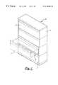
- FIG. 1is a perspective view of a file cabinet incorporating the locking system of the present invention
- FIG. 2is an enlarged perspective view of the locking system
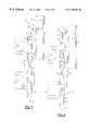
- FIG. 3is a side view of the locking system in a locked position
- FIG. 4is a side view of the locking system in an unlocked position
- FIG. 5is a partial view of the locking system in the locked position
- FIG. 6is a partial view of the locking system in the unlocked position
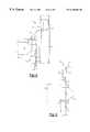
- FIG. 7is an exploded view of the locking system
- FIGS. 8A and 8Bare perspective views of a locking cam of the locking system.
- FIGS. 1 and 2there is shown two embodiments of a filing cabinet 10 incorporating a locking system embodied in the present invention.
- the filing cabinet 10is a lateral file cabinet with a plurality of selectively extractable file drawers 12 .
- the file drawers 12are positioned in a vertical orientation and are independently selectively movable between a stored position within the cabinet housing 14 and an extended position exteriorly of the housing 14 for access to the contents of the drawer 12 .
- the individual drawers 12are supported on a slider assembly 16 which facilitate lateral movement of the drawer 12 into and out of the cabinet housing 14 .
- the embodiment of FIG. 2includes four extractable file drawers 12 for storage of files and records.
- the embodiment of FIG. 1includes a flip door 18 to provide selective access to the interior storage area 20 at the top of the cabinet 10 .
- Both embodiments of the file cabinet 10incorporate locking systems to secure the drawers and flip door controlling access to the interior storage area 20 at the top of the cabinet 10 .
- the locking system 22 of the present inventionoperates in conjunction with the interlocking mechanism of the cabinet 10 which prevents more than one drawer 12 from being opened.
- the locking system 22is incorporated into the side wall of the cabinet 10 and operated by a key (not shown).
- the primary component of the locking system 22is a rotatable cam 24 .
- the cam 24includes a hook member 26 and a flange 28 .
- the cam 24cooperates with a lock cylinder 30 for rotation under operation of a key. Rotation of the cam 24 in a first direction will cause the hook member 26 to engage an opening 32 in a front panel 34 of the flipper door 18 or drawer 12 . Once inserted into the opening 32 , the drawer 12 or door 18 is prevented from being opened.
- a single simple locking system 22operates in cooperation with the interlock 36 of the cabinet 10 to selectively lock all of the drawers of the cabinet 10 .
- the interlocking mechanism 36 of the file cabinet 10operates to allow opening of only one drawer 12 at any time. Upon opening of one drawer 12 , the interlocking mechanism 36 prevents the subsequent opening of additional drawers 12 .
- the interlocking mechanism 36cooperates with the sliders 16 of each of the drawers 12 and includes a clamp 38 adjacent each slider 16 .
- the clamps 38 of the interlocking mechanism 36are connected by a rod 42 such that the clamps 38 operate in unison.
- the slider 16has a tapered forward end 40 which allows the clamp 38 to contract when the drawer 12 is pushed in the cabinet housing 14 . As the slider 16 moves through the clamp 38 when the drawer 12 is pulled from the cabinet 10 , the clamp 38 is expanded.
- the clamp halves 44drive respective connecting rods 42 outwardly to hold the other clamps 38 in a contracted or closed position preventing the respective sliders 16 from moving through the clamps 38 . Accordingly, only one drawer 12 may be opened in the file cabinet 10 .
- the lock assembly 22operates in conjunction with the interlocking mechanism 36 to prevent withdrawal of the file drawers 12 when the assembly 22 is locked.
- Rotation of the cam 24 from the unlocked position to a lock positioncauses the hook 26 to engage and retain the front panel 34 .
- the flange 28rotates downwardly to engage the uppermost clamp 38 preventing expansion of the clamps 38 to receive the slider 16 .
- With the clamps 38 maintained in a contracted positionnone of the drawers 12 can be opened.
- Rotation of the cam 24 to an unlocked position(FIGS. 5 and 7) not only releases the front panel 34 but also releases the interlocking mechanism. As a result, one of the drawers 12 can be opened as necessary.
Landscapes
- Drawers Of Furniture (AREA)
Abstract
Description
This application claims the benefit and priority of U.S. Provisional Application No. 60/104,688 filed Oct. 17, 1998.
I. Field of the Invention
This invention relates to a locking system for a file cabinet and, in particular, to a rotatable cam lock which engages the individual drawer and simultaneously blocks the interlocking mechanism of the file system.
II. Background of the Invention
File systems typically include a plurality of drawers or cabinet doors positioned in a vertical arrangement to maximize storage space. In the case of drawers, the individual drawers are slidably extractable from the cabinet to allow access to the interior contents of the drawer. A flip up door may be employed to enclose the individual storage units facilitating access from the front of the unit rather than the top as in a drawer. In order to maintain stability of the cabinet, it is preferred that only one drawer be allowed to be extracted at a time. Interlocking systems have long been employed which prevent multiple drawers from being opened in such cabinets. However, the prior known file systems employ interlocking systems which are separate from the overall locking assembly for the cabinet. The increased part requirements for such a separate locking system increases the costs and complexity of manufacturing of the cabinet.
The present invention overcomes the disadvantages of the prior known file cabinets by providing a simple locking system which engages the individual file drawer or door while also blocking the interlocking mechanism of the cabinet to control opening of the drawers.
The file cabinet of the present invention incorporates a plurality of file drawers positioned vertically within the cabinet for individual extraction from the cabinet. The drawers ride on a slider assembly for simple movement into and out of the cabinet. The locking system is incorporated into the side wall of the cabinet for engagement with the individual drawers for locking the entire cabinet preventing extraction of any of the drawers. The lock assembly is a single cam lock which hooks into a front panel of the uppermost drawer and engages the interlocking mechanism of the cabinet thereby preventing the other drawers from being opened.
The locking assembly includes a key-operated spindle rotatable within the cabinet wall. Mounted to the rotatable spindle is a lever hook which is movable between an unlocked position and a locked position. The lever hook includes a hook and an end-plate. In the locked position the hook is inserted into an aperture of the front panel of the cabinet while the end plate engages the interlocking mechanism preventing extraction of the drawers. The interlocking mechanisms controls movement of the drawers when one of the drawers has been pulled out. As a result, a simple, single locking mechanism is used to control access to the contents of the file cabinet.
Other objects, features and advantages of the invention will be apparent from the detailed description taken in connection with the accompanying drawings.
The present invention will be more fully understood by reference to the following detailed description of a preferred embodiment of the present invention when read in conjunction with the accompanying drawing, in which like reference characters refer to like parts throughout the views and in which:
FIG. 1 is a perspective view of a file cabinet incorporating the locking system of the present invention;
FIG. 2 is an enlarged perspective view of the locking system;
FIG. 3 is a side view of the locking system in a locked position;
FIG. 4 is a side view of the locking system in an unlocked position;
FIG. 5 is a partial view of the locking system in the locked position;
FIG. 6 is a partial view of the locking system in the unlocked position;
FIG. 7 is an exploded view of the locking system; and
FIGS. 8A and 8B are perspective views of a locking cam of the locking system.
Referring first to FIGS. 1 and 2, there is shown two embodiments of afiling cabinet 10 incorporating a locking system embodied in the present invention. Thefiling cabinet 10 is a lateral file cabinet with a plurality of selectivelyextractable file drawers 12. Thefile drawers 12 are positioned in a vertical orientation and are independently selectively movable between a stored position within thecabinet housing 14 and an extended position exteriorly of thehousing 14 for access to the contents of thedrawer 12. In a well known manner, theindividual drawers 12 are supported on aslider assembly 16 which facilitate lateral movement of thedrawer 12 into and out of thecabinet housing 14. The embodiment of FIG. 2 includes fourextractable file drawers 12 for storage of files and records. In place of the top drawer, the embodiment of FIG. 1 includes a flip door18 to provide selective access to the interior storage area20 at the top of thecabinet 10. Both embodiments of thefile cabinet 10 incorporate locking systems to secure the drawers and flip door controlling access to the interior storage area20 at the top of thecabinet 10.
Referring now to FIGS. 3 through 7, thelocking system 22 of the present invention operates in conjunction with the interlocking mechanism of thecabinet 10 which prevents more than onedrawer 12 from being opened. Thelocking system 22 is incorporated into the side wall of thecabinet 10 and operated by a key (not shown). The primary component of thelocking system 22 is arotatable cam 24. Thecam 24 includes ahook member 26 and aflange 28. Thecam 24 cooperates with alock cylinder 30 for rotation under operation of a key. Rotation of thecam 24 in a first direction will cause thehook member 26 to engage anopening 32 in afront panel 34 of the flipper door18 ordrawer 12. Once inserted into theopening 32, thedrawer 12 or door18 is prevented from being opened. Simultaneously, theflange 28 of therotatable cam 24 is rotated into engagement with theinterlocking mechanism 36 of thecabinet 10 preventing opening of theother drawers 12 as will be subsequently described. As a result, a singlesimple locking system 22 operates in cooperation with theinterlock 36 of thecabinet 10 to selectively lock all of the drawers of thecabinet 10.
Theinterlocking mechanism 36 of thefile cabinet 10 operates to allow opening of only onedrawer 12 at any time. Upon opening of onedrawer 12, theinterlocking mechanism 36 prevents the subsequent opening ofadditional drawers 12. Theinterlocking mechanism 36 cooperates with thesliders 16 of each of thedrawers 12 and includes aclamp 38 adjacent eachslider 16. Theclamps 38 of theinterlocking mechanism 36 are connected by arod 42 such that theclamps 38 operate in unison. Theslider 16 has a taperedforward end 40 which allows theclamp 38 to contract when thedrawer 12 is pushed in thecabinet housing 14. As theslider 16 moves through theclamp 38 when thedrawer 12 is pulled from thecabinet 10, theclamp 38 is expanded. Theclamp halves 44 drive respective connectingrods 42 outwardly to hold theother clamps 38 in a contracted or closed position preventing therespective sliders 16 from moving through theclamps 38. Accordingly, only onedrawer 12 may be opened in thefile cabinet 10.
Thelock assembly 22 operates in conjunction with theinterlocking mechanism 36 to prevent withdrawal of thefile drawers 12 when theassembly 22 is locked. Rotation of thecam 24 from the unlocked position to a lock position (FIGS. 4 and 6) causes thehook 26 to engage and retain thefront panel 34. Additionally, theflange 28 rotates downwardly to engage theuppermost clamp 38 preventing expansion of theclamps 38 to receive theslider 16. With theclamps 38 maintained in a contracted position, none of thedrawers 12 can be opened. Rotation of thecam 24 to an unlocked position (FIGS. 5 and 7) not only releases thefront panel 34 but also releases the interlocking mechanism. As a result, one of thedrawers 12 can be opened as necessary.
The foregoing detailed description has been given for clearness of understanding only and no unnecessary limitations should be understood therefrom as some modifications will be obvious to those skilled in the art without departing from the scope and spirit of the appended claims.
Claims (9)
1. In a file cabinet having a plurality of drawers selectively movable between a closed position disposed within said cabinet and an open position slidably extended from within said cabinet to provide access to the contents of said drawers, said file cabinet including an interlocking mechanism cooperating with said drawers to prevent more than one of said drawers from being opened simultaneously, the improvement comprising:
a locking assembly having a rotatable locking cam movable between an unlocked position allowing opening of said drawers and operation of said interlocking mechanism and movement of said drawers to said open position, said rotatable locking cam including a hook member formed in a plane and movable upon rotation of said locking cam between an unlocked position and a locked position engaging a front panel of said file cabinet and wherein said locking cam includes a flange which selectively engages said interlocking mechanism upon rotation of said locking cam to said locked position.
2. The improvement as defined in claim1 wherein said hook member is disposed in said plane substantially perpendicular to the plane of said flange on said locking cam.
3. The improvement as defined in claim2 wherein said front panel of said file cabinet has an opening for selectively receiving said hook member, positioning of said hook member within said opening upon rotation of said locking cam to said locked position prevents opening of said front panel.
4. The improvement as defined in claim1 wherein said flange of said locking cam engages a clamp member of said interlocking mechanism upon rotation of said locking cam to said locked position, said flange preventing said clamp member from expanding when in said locked position.
5. The improvement as defined in claim1 wherein said locking cam is operated by key means inserted into said locking assembly facilitating rotation of said locking cam between said unlocked and locked positions.
6. In a file cabinet having a plurality of drawers selectively movable between a concealed position disposed within said cabinet and an open position slidably extended from within said cabinet to allow access to the contents of said drawers, said file cabinet including an interlocking mechanism extending between said drawers to prevent more than one of said drawers from being open simultaneously, the improvement comprising:
a locking assembly having a rotatable locking cam with a flange pivotably movable between an unlocked position allowing operation of said interlocking mechanism and opening of said drawers and a locked position engaging said interlocking mechanism preventing operation of said interlocking mechanism thereby preventing movement of said drawers to said open position, said rotatable locking cam including a hook member formed in a plane and movable upon rotation of said locking cam between an unlocked position and a locked position engaging a front panel of said file cabinet to prevent movement of said front panel.
7. The improvement as defined in claim6 wherein said flange for selectively engaging said interlocking mechanism extends perpendicular to the axis of rotation of said locking cam.
8. The improvement as defined in claim7 wherein said flange of said locking cam engages a clamp member of said interlocking mechanism to prevent expansion of said clamp member upon rotation of said locking cam to said locked position, said flange preventing said clamp member from expanding thereby preventing operation of said drawers.
9. The improvement as defined in claim7 wherein said front panel of said file cabinet has an opening for selectively receiving said hook member whereby positioning of said hook member within said opening upon rotation of said locking cam to said locked position prevents opening of said front panel.
Priority Applications (1)
| Application Number | Priority Date | Filing Date | Title |
|---|---|---|---|
| US09/190,549US6186606B1 (en) | 1998-10-17 | 1998-11-12 | Lateral File Locking System |
Applications Claiming Priority (2)
| Application Number | Priority Date | Filing Date | Title |
|---|---|---|---|
| US10468898P | 1998-10-17 | 1998-10-17 | |
| US09/190,549US6186606B1 (en) | 1998-10-17 | 1998-11-12 | Lateral File Locking System |
Publications (1)
| Publication Number | Publication Date |
|---|---|
| US6186606B1true US6186606B1 (en) | 2001-02-13 |
Family
ID=26801837
Family Applications (1)
| Application Number | Title | Priority Date | Filing Date |
|---|---|---|---|
| US09/190,549Expired - Fee RelatedUS6186606B1 (en) | 1998-10-17 | 1998-11-12 | Lateral File Locking System |
Country Status (1)
| Country | Link |
|---|---|
| US (1) | US6186606B1 (en) |
Cited By (16)
| Publication number | Priority date | Publication date | Assignee | Title |
|---|---|---|---|---|
| US20040100165A1 (en)* | 2002-11-27 | 2004-05-27 | Hoffman Keith A. | Interlock mechanism for lateral file cab inets |
| US20050204646A1 (en)* | 2004-03-19 | 2005-09-22 | Tupper Paul L | Pedestal system |
| US20060186776A1 (en)* | 2004-12-30 | 2006-08-24 | Tung Chien Industries Co., Ltd. | Cabinet having drawer locking device |
| US20070176523A1 (en)* | 2006-01-31 | 2007-08-02 | Ching-Hsiang Lin | Cabinet with a safety device |
| US20080113820A1 (en)* | 2006-11-10 | 2008-05-15 | Igt | Controlled access of secure area within a gaming machine using display |
| US7484817B2 (en) | 2002-11-27 | 2009-02-03 | Knape & Vogt Manufacturing Co. | Interlock mechanism for lateral file cabinets |
| AU2004203362B2 (en)* | 2003-07-23 | 2010-04-01 | Walter Bachmann | A safety cabinet |
| US20100123375A1 (en)* | 2008-11-17 | 2010-05-20 | Versatility Tool Works & Manufacturing Company, Inc. | Locking System for Filing Cabinets to Prevent More than One Drawer being Open at One Time |
| GB2493227A (en)* | 2011-07-21 | 2013-01-30 | Sun Chain Metal Industry Co Ltd | Slide mechanism with interlock |
| US10145149B2 (en) | 2014-02-06 | 2018-12-04 | 2603701 Ontario Inc. | Cammed lever-activated locking system |
| US10470572B1 (en)* | 2018-10-08 | 2019-11-12 | Martas Precision Slide Co., Ltd. | Locking device for slide rail |
| US10966520B2 (en)* | 2019-01-15 | 2021-04-06 | Martas Precision Slide Co., Ltd. | Cabinet locking device |
| US11549286B1 (en)* | 2021-12-07 | 2023-01-10 | Yi-Chun Chen | Lock bar-on-slide rail style drawer antitipping safety device |
| KR102638611B1 (en)* | 2023-04-26 | 2024-02-20 | 주식회사 한독하이테크 | Safety Apparatus Preventing from Simultaneous Opening of Large Volume Multistep Drawer |
| US12000177B2 (en) | 2020-02-12 | 2024-06-04 | Raytheon Company | Drawer system and drawer lock |
| US20240268555A1 (en)* | 2023-02-14 | 2024-08-15 | King Slide Works Co., Ltd. | Slide rail mechanism |
Citations (29)
| Publication number | Priority date | Publication date | Assignee | Title |
|---|---|---|---|---|
| GB189925176A (en)* | 1899-12-19 | 1900-02-03 | Frederick William Schafer | Improvements in or relating to Filing Cabinets and the like. |
| US1013444A (en) | 1911-10-07 | 1912-01-02 | George Robbins | Multicompartment cabinet. |
| US1740672A (en) | 1928-11-10 | 1929-12-24 | Berger Mfg Co | Latch for lockers |
| US2097504A (en) | 1936-05-29 | 1937-11-02 | Milton H Wells | Lock latch |
| US2448748A (en) | 1946-03-04 | 1948-09-07 | Grand Rapids Store Equip Co | Sliding door lock |
| US2750901A (en) | 1953-05-18 | 1956-06-19 | Meilink Steel Safe Company | Insulated metal cabinet construction |
| US2882112A (en) | 1956-12-04 | 1959-04-14 | Haskell Mfg Co Inc | Drawer lock |
| FR1255213A (en)* | 1960-04-21 | 1961-03-03 | Desoer Sa | Device for locking and retaining drawers in a cabinet |
| US3223466A (en) | 1963-11-12 | 1965-12-14 | Holga Metal Production Company | Filing cabinet |
| FR1454844A (en)* | 1964-11-25 | 1966-10-07 | Velox Werke Herbert Schnelle | Office furniture |
| US3649095A (en) | 1970-09-21 | 1972-03-14 | Art Lloyd Metal Products Corp | Pilfer-proof desk and work table drawer |
| US3936108A (en)* | 1975-02-24 | 1976-02-03 | Oxford Pendaflex Corporation | File cabinet drawer locking mechanism |
| US4040653A (en)* | 1975-06-19 | 1977-08-09 | Mitsubishi Denki Kabushiki Kaisha | Control device for stopping the withdrawing of unit cases |
| US4132440A (en) | 1977-09-19 | 1979-01-02 | General Electric Company | Locking arrangement for a household refrigerator |
| CA1084096A (en)* | 1978-09-20 | 1980-08-19 | Storwal International Inc. | Cam for cabinet locking system |
| US4239309A (en) | 1979-07-31 | 1980-12-16 | Lear Siegler, Inc. | Filing cabinet including drawer interlock |
| GB1584777A (en)* | 1977-10-18 | 1981-02-18 | Vickers Ltd | Autolock mechanism in a storage cabinet |
| FR2523631A1 (en)* | 1982-03-19 | 1983-09-23 | Jacques Roland | Drawer stop for superimposed drawer cupboards - has ramps on drawers to move frame and lock other drawers when one is removed |
| US4453787A (en)* | 1981-06-11 | 1984-06-12 | Staropoli Paul R | Interchangeable file cabinet lock assembly |
| US4465328A (en) | 1982-06-21 | 1984-08-14 | Northern Telecom Limited | Rotating latch with positive indication of latching |
| US4477130A (en) | 1983-02-10 | 1984-10-16 | Tread Corporation | Security cabinet for storage of valuables |
| US4525012A (en) | 1982-05-12 | 1985-06-25 | Lista Ag | Locking apparatus for drawers and the like |
| US4662689A (en) | 1985-05-10 | 1987-05-05 | Haworth, Inc. | Lock mechanism for lateral file |
| US4820002A (en)* | 1987-11-24 | 1989-04-11 | Tab Products Company | Safety interlock |
| US5176436A (en)* | 1991-10-21 | 1993-01-05 | Quest Engineering, Ltd. | Strap type drawer interlock structure |
| US5199774A (en)* | 1990-11-27 | 1993-04-06 | Kimball International, Inc. | Combination lock and interlock for a file cabinet |
| US5249443A (en) | 1992-09-08 | 1993-10-05 | Loctec Corporation | Front-installed dual cam lock with pivoting cams |
| US5292191A (en) | 1991-11-25 | 1994-03-08 | Snap-On Tools Corporation | Latch mechanism for a cabinet drawer |
| US5988778A (en)* | 1996-07-12 | 1999-11-23 | Accuride International, Inc. | Rod-based file interlock system |
- 1998
- 1998-11-12USUS09/190,549patent/US6186606B1/ennot_activeExpired - Fee Related
Patent Citations (29)
| Publication number | Priority date | Publication date | Assignee | Title |
|---|---|---|---|---|
| GB189925176A (en)* | 1899-12-19 | 1900-02-03 | Frederick William Schafer | Improvements in or relating to Filing Cabinets and the like. |
| US1013444A (en) | 1911-10-07 | 1912-01-02 | George Robbins | Multicompartment cabinet. |
| US1740672A (en) | 1928-11-10 | 1929-12-24 | Berger Mfg Co | Latch for lockers |
| US2097504A (en) | 1936-05-29 | 1937-11-02 | Milton H Wells | Lock latch |
| US2448748A (en) | 1946-03-04 | 1948-09-07 | Grand Rapids Store Equip Co | Sliding door lock |
| US2750901A (en) | 1953-05-18 | 1956-06-19 | Meilink Steel Safe Company | Insulated metal cabinet construction |
| US2882112A (en) | 1956-12-04 | 1959-04-14 | Haskell Mfg Co Inc | Drawer lock |
| FR1255213A (en)* | 1960-04-21 | 1961-03-03 | Desoer Sa | Device for locking and retaining drawers in a cabinet |
| US3223466A (en) | 1963-11-12 | 1965-12-14 | Holga Metal Production Company | Filing cabinet |
| FR1454844A (en)* | 1964-11-25 | 1966-10-07 | Velox Werke Herbert Schnelle | Office furniture |
| US3649095A (en) | 1970-09-21 | 1972-03-14 | Art Lloyd Metal Products Corp | Pilfer-proof desk and work table drawer |
| US3936108A (en)* | 1975-02-24 | 1976-02-03 | Oxford Pendaflex Corporation | File cabinet drawer locking mechanism |
| US4040653A (en)* | 1975-06-19 | 1977-08-09 | Mitsubishi Denki Kabushiki Kaisha | Control device for stopping the withdrawing of unit cases |
| US4132440A (en) | 1977-09-19 | 1979-01-02 | General Electric Company | Locking arrangement for a household refrigerator |
| GB1584777A (en)* | 1977-10-18 | 1981-02-18 | Vickers Ltd | Autolock mechanism in a storage cabinet |
| CA1084096A (en)* | 1978-09-20 | 1980-08-19 | Storwal International Inc. | Cam for cabinet locking system |
| US4239309A (en) | 1979-07-31 | 1980-12-16 | Lear Siegler, Inc. | Filing cabinet including drawer interlock |
| US4453787A (en)* | 1981-06-11 | 1984-06-12 | Staropoli Paul R | Interchangeable file cabinet lock assembly |
| FR2523631A1 (en)* | 1982-03-19 | 1983-09-23 | Jacques Roland | Drawer stop for superimposed drawer cupboards - has ramps on drawers to move frame and lock other drawers when one is removed |
| US4525012A (en) | 1982-05-12 | 1985-06-25 | Lista Ag | Locking apparatus for drawers and the like |
| US4465328A (en) | 1982-06-21 | 1984-08-14 | Northern Telecom Limited | Rotating latch with positive indication of latching |
| US4477130A (en) | 1983-02-10 | 1984-10-16 | Tread Corporation | Security cabinet for storage of valuables |
| US4662689A (en) | 1985-05-10 | 1987-05-05 | Haworth, Inc. | Lock mechanism for lateral file |
| US4820002A (en)* | 1987-11-24 | 1989-04-11 | Tab Products Company | Safety interlock |
| US5199774A (en)* | 1990-11-27 | 1993-04-06 | Kimball International, Inc. | Combination lock and interlock for a file cabinet |
| US5176436A (en)* | 1991-10-21 | 1993-01-05 | Quest Engineering, Ltd. | Strap type drawer interlock structure |
| US5292191A (en) | 1991-11-25 | 1994-03-08 | Snap-On Tools Corporation | Latch mechanism for a cabinet drawer |
| US5249443A (en) | 1992-09-08 | 1993-10-05 | Loctec Corporation | Front-installed dual cam lock with pivoting cams |
| US5988778A (en)* | 1996-07-12 | 1999-11-23 | Accuride International, Inc. | Rod-based file interlock system |
Cited By (26)
| Publication number | Priority date | Publication date | Assignee | Title |
|---|---|---|---|---|
| US7293845B2 (en) | 2002-11-27 | 2007-11-13 | Knape & Vogt Manufacturing Company | Interlock mechanism for lateral file cabinets |
| US6779855B2 (en) | 2002-11-27 | 2004-08-24 | Knape & Vogt Manufacturing Co. | Interlock mechanism for lateral file cabinets |
| US7063398B2 (en) | 2002-11-27 | 2006-06-20 | Keith A Hoffman | Interlock mechanism for lateral file cabinets |
| US7484817B2 (en) | 2002-11-27 | 2009-02-03 | Knape & Vogt Manufacturing Co. | Interlock mechanism for lateral file cabinets |
| US20040100165A1 (en)* | 2002-11-27 | 2004-05-27 | Hoffman Keith A. | Interlock mechanism for lateral file cab inets |
| AU2004203362B2 (en)* | 2003-07-23 | 2010-04-01 | Walter Bachmann | A safety cabinet |
| US20050204646A1 (en)* | 2004-03-19 | 2005-09-22 | Tupper Paul L | Pedestal system |
| US7469979B2 (en) | 2004-03-19 | 2008-12-30 | Steelcase Inc. | Pedestal system |
| US20060186776A1 (en)* | 2004-12-30 | 2006-08-24 | Tung Chien Industries Co., Ltd. | Cabinet having drawer locking device |
| US20070176523A1 (en)* | 2006-01-31 | 2007-08-02 | Ching-Hsiang Lin | Cabinet with a safety device |
| US7309114B2 (en)* | 2006-01-31 | 2007-12-18 | Ching-Hsiang Lin | Cabinet with a safety device |
| US8579712B2 (en)* | 2006-11-10 | 2013-11-12 | Igt | Controlled access of secure area within a gaming machine using display |
| US20080113820A1 (en)* | 2006-11-10 | 2008-05-15 | Igt | Controlled access of secure area within a gaming machine using display |
| US20100123375A1 (en)* | 2008-11-17 | 2010-05-20 | Versatility Tool Works & Manufacturing Company, Inc. | Locking System for Filing Cabinets to Prevent More than One Drawer being Open at One Time |
| US8696074B2 (en)* | 2008-11-17 | 2014-04-15 | Andrew Romaen | Safety lock system for cabinet drawers |
| US8371664B1 (en)* | 2011-07-21 | 2013-02-12 | Sun Chain Metal Industry Co., Ltd. | Interlocking device for a drawer slide |
| GB2493227A (en)* | 2011-07-21 | 2013-01-30 | Sun Chain Metal Industry Co Ltd | Slide mechanism with interlock |
| GB2493227B (en)* | 2011-07-21 | 2015-03-25 | Sun Chain Metal Industry Co Ltd | Interlocking device for a drawer slide |
| US10145149B2 (en) | 2014-02-06 | 2018-12-04 | 2603701 Ontario Inc. | Cammed lever-activated locking system |
| US10470572B1 (en)* | 2018-10-08 | 2019-11-12 | Martas Precision Slide Co., Ltd. | Locking device for slide rail |
| US10966520B2 (en)* | 2019-01-15 | 2021-04-06 | Martas Precision Slide Co., Ltd. | Cabinet locking device |
| US12000177B2 (en) | 2020-02-12 | 2024-06-04 | Raytheon Company | Drawer system and drawer lock |
| US11549286B1 (en)* | 2021-12-07 | 2023-01-10 | Yi-Chun Chen | Lock bar-on-slide rail style drawer antitipping safety device |
| US20240268555A1 (en)* | 2023-02-14 | 2024-08-15 | King Slide Works Co., Ltd. | Slide rail mechanism |
| US12364331B2 (en)* | 2023-02-14 | 2025-07-22 | King Slide Works Co., Ltd. | Slide rail mechanism |
| KR102638611B1 (en)* | 2023-04-26 | 2024-02-20 | 주식회사 한독하이테크 | Safety Apparatus Preventing from Simultaneous Opening of Large Volume Multistep Drawer |
Similar Documents
| Publication | Publication Date | Title |
|---|---|---|
| US6186606B1 (en) | Lateral File Locking System | |
| US4239309A (en) | Filing cabinet including drawer interlock | |
| US4637667A (en) | Positive interlock for file cabinet | |
| US8235475B2 (en) | Anti-tip interlocking linkage mechanism for vertical cabinets | |
| US5303994A (en) | Drawer interlock | |
| US6969129B2 (en) | Anti-tip interlocking linkage mechanism for vertical cabinets | |
| US7946663B2 (en) | Drawer lock mechanism | |
| US5056877A (en) | Locking anti-tip device | |
| US5931548A (en) | Drawer interlock to non-interlock conversion device | |
| US5044182A (en) | Automatic deadbolt | |
| US2886392A (en) | Safe cabinet locking device | |
| US20060220503A1 (en) | Locking system for top box mounted on roll-away cabinet | |
| US3637277A (en) | Entry resistant security file construction | |
| US4955672A (en) | Drawer interlock | |
| US5791174A (en) | Paddle handle locks | |
| US3936108A (en) | File cabinet drawer locking mechanism | |
| US3998508A (en) | Gang locking mechanism | |
| US5567027A (en) | Cabinet drawer lock | |
| US4688492A (en) | Two door safe | |
| US20080074016A1 (en) | Filing cabinet with a locking system | |
| CN1121739A (en) | Non-handed door latch for passage and privacy functions | |
| US3511549A (en) | Cabinet locking mechanism | |
| US4813251A (en) | Four point locking system for storage cabinets | |
| US8596729B2 (en) | Releasable tenon for locking system | |
| GB1587567A (en) | Locking mechanism |
Legal Events
| Date | Code | Title | Description |
|---|---|---|---|
| AS | Assignment | Owner name:MARVEL GROUP, INC., THE, ILLINOIS Free format text:ASSIGNMENT OF ASSIGNORS INTEREST;ASSIGNOR:KREI, CHRISTOPHER J.;REEL/FRAME:010353/0102 Effective date:19990407 | |
| AS | Assignment | Owner name:LASALLE BANK NATIONAL ASSOCIATION, ILLINOIS Free format text:ASSIGNMENT OF ASSIGNORS INTEREST;ASSIGNOR:MARVEL GROUP, INC., THE;REEL/FRAME:014560/0616 Effective date:20030930 | |
| REMI | Maintenance fee reminder mailed | ||
| LAPS | Lapse for failure to pay maintenance fees | ||
| STCH | Information on status: patent discontinuation | Free format text:PATENT EXPIRED DUE TO NONPAYMENT OF MAINTENANCE FEES UNDER 37 CFR 1.362 | |
| FP | Lapsed due to failure to pay maintenance fee | Effective date:20050213 | |
| AS | Assignment | Owner name:MB FINANCIAL BANK, N.A., ILLINOIS Free format text:SECURITY AGREEMENT;ASSIGNOR:THE MARVEL GROUP, INC.;REEL/FRAME:020174/0117 Effective date:20071128 |