US6186361B1 - Liquid dispenser - Google Patents
Liquid dispenserDownload PDFInfo
- Publication number
- US6186361B1 US6186361B1US09/510,936US51093600AUS6186361B1US 6186361 B1US6186361 B1US 6186361B1US 51093600 AUS51093600 AUS 51093600AUS 6186361 B1US6186361 B1US 6186361B1
- Authority
- US
- United States
- Prior art keywords
- container
- liquid
- dispenser
- passage
- connector
- Prior art date
- Legal status (The legal status is an assumption and is not a legal conclusion. Google has not performed a legal analysis and makes no representation as to the accuracy of the status listed.)
- Expired - Lifetime
Links
- 239000007788liquidSubstances0.000titleclaimsabstractdescription104
- 238000001816coolingMethods0.000claimsabstractdescription19
- 230000005484gravityEffects0.000claimsabstractdescription12
- 230000001105regulatory effectEffects0.000claimsabstractdescription9
- 239000012080ambient airSubstances0.000claimsabstractdescription3
- 238000000034methodMethods0.000claimsabstract4
- 230000007246mechanismEffects0.000claimsdescription6
- 239000003570airSubstances0.000claimsdescription5
- 230000002093peripheral effectEffects0.000claims3
- 238000007789sealingMethods0.000claims2
- 238000003860storageMethods0.000description27
- 238000005192partitionMethods0.000description10
- 239000004033plasticSubstances0.000description9
- 229920003023plasticPolymers0.000description9
- 238000004140cleaningMethods0.000description6
- 239000006071creamSubstances0.000description5
- NJPPVKZQTLUDBO-UHFFFAOYSA-NnovaluronChemical compoundC1=C(Cl)C(OC(F)(F)C(OC(F)(F)F)F)=CC=C1NC(=O)NC(=O)C1=C(F)C=CC=C1FNJPPVKZQTLUDBO-UHFFFAOYSA-N0.000description5
- 238000004891communicationMethods0.000description4
- 230000001276controlling effectEffects0.000description4
- 239000000463materialSubstances0.000description4
- 238000005057refrigerationMethods0.000description4
- 238000012546transferMethods0.000description4
- 230000008878couplingEffects0.000description3
- 238000010168coupling processMethods0.000description3
- 238000005859coupling reactionMethods0.000description3
- 230000005496eutecticsEffects0.000description3
- 239000012530fluidSubstances0.000description3
- 239000011810insulating materialSubstances0.000description3
- 238000009413insulationMethods0.000description3
- 238000004519manufacturing processMethods0.000description3
- 239000003507refrigerantSubstances0.000description3
- 238000009833condensationMethods0.000description2
- 230000005494condensationEffects0.000description2
- 238000010276constructionMethods0.000description2
- 230000000994depressogenic effectEffects0.000description2
- 235000013305foodNutrition0.000description2
- 235000021056liquid foodNutrition0.000description2
- 229910052751metalInorganic materials0.000description2
- 239000002184metalSubstances0.000description2
- 238000012986modificationMethods0.000description2
- 230000004048modificationEffects0.000description2
- 230000000717retained effectEffects0.000description2
- RYGMFSIKBFXOCR-UHFFFAOYSA-NCopperChemical compound[Cu]RYGMFSIKBFXOCR-UHFFFAOYSA-N0.000description1
- 239000004593EpoxySubstances0.000description1
- 239000004698PolyethyleneSubstances0.000description1
- 241000490025Schefflera digitataSpecies0.000description1
- 229920006328StyrofoamPolymers0.000description1
- 230000006978adaptationEffects0.000description1
- 229910052782aluminiumInorganic materials0.000description1
- XAGFODPZIPBFFR-UHFFFAOYSA-NaluminiumChemical compound[Al]XAGFODPZIPBFFR-UHFFFAOYSA-N0.000description1
- 230000008859changeEffects0.000description1
- 229910052802copperInorganic materials0.000description1
- 239000010949copperSubstances0.000description1
- 230000003670easy-to-cleanEffects0.000description1
- 238000001125extrusionMethods0.000description1
- 229920002457flexible plasticPolymers0.000description1
- 239000004519greaseSubstances0.000description1
- 238000002347injectionMethods0.000description1
- 239000007924injectionSubstances0.000description1
- 235000015250liver sausagesNutrition0.000description1
- 238000012423maintenanceMethods0.000description1
- 239000007769metal materialSubstances0.000description1
- 230000000813microbial effectEffects0.000description1
- 238000000465mouldingMethods0.000description1
- -1polyethylenePolymers0.000description1
- 229920000573polyethylenePolymers0.000description1
- 239000004800polyvinyl chlorideSubstances0.000description1
- 229920000915polyvinyl chloridePolymers0.000description1
- 238000001175rotational mouldingMethods0.000description1
- 238000010079rubber tappingMethods0.000description1
- 239000007787solidSubstances0.000description1
- 239000011493spray foamSubstances0.000description1
- 239000010935stainless steelSubstances0.000description1
- 229910001220stainless steelInorganic materials0.000description1
- 239000008261styrofoamSubstances0.000description1
- 229920001169thermoplasticPolymers0.000description1
- 239000012815thermoplastic materialSubstances0.000description1
- 239000004416thermosoftening plasticSubstances0.000description1
Images


Classifications
- B—PERFORMING OPERATIONS; TRANSPORTING
- B67—OPENING, CLOSING OR CLEANING BOTTLES, JARS OR SIMILAR CONTAINERS; LIQUID HANDLING
- B67B—APPLYING CLOSURE MEMBERS TO BOTTLES JARS, OR SIMILAR CONTAINERS; OPENING CLOSED CONTAINERS
- B67B7/00—Hand- or power-operated devices for opening closed containers
- B67B7/24—Hole-piercing devices
- B67B7/26—Hole-piercing devices combined with spouts
- B—PERFORMING OPERATIONS; TRANSPORTING
- B67—OPENING, CLOSING OR CLEANING BOTTLES, JARS OR SIMILAR CONTAINERS; LIQUID HANDLING
- B67D—DISPENSING, DELIVERING OR TRANSFERRING LIQUIDS, NOT OTHERWISE PROVIDED FOR
- B67D3/00—Apparatus or devices for controlling flow of liquids under gravity from storage containers for dispensing purposes
- B67D3/0009—Apparatus or devices for controlling flow of liquids under gravity from storage containers for dispensing purposes provided with cooling arrangements
- B—PERFORMING OPERATIONS; TRANSPORTING
- B67—OPENING, CLOSING OR CLEANING BOTTLES, JARS OR SIMILAR CONTAINERS; LIQUID HANDLING
- B67D—DISPENSING, DELIVERING OR TRANSFERRING LIQUIDS, NOT OTHERWISE PROVIDED FOR
- B67D3/00—Apparatus or devices for controlling flow of liquids under gravity from storage containers for dispensing purposes
- B67D3/04—Liquid-dispensing taps or cocks adapted to seal and open tapping holes of casks, e.g. for beer
- B67D3/041—Liquid-dispensing taps or cocks adapted to seal and open tapping holes of casks, e.g. for beer operated by pinching action on flexible tubes
Definitions
- This inventionpertains to dispensers for dispensing a liquid food product, such as cream. More particularly, it relates to such a liquid dispenser having a clamping means to regulate liquid flow from the dispenser and a cooling means to cool the liquid to the dispensing point and as it flows from the container.
- Liquid dispensersare well-known in food service applications.
- a liquid dispenseris a cream dispenser.
- such dispensersinclude a dispenser housing, which contains a reservoir for holding the liquid to be dispensed, and a valve assembly for dispensing the cream.
- the housing and reservoirare made of stainless steel, plastic, or other durable material acceptable for food contact, and the housing is usually provided with suitable thermal insulation.
- the reservoirmay comprise a container or frame that supports a bag or liner that is pre-filled with the liquid to be dispensed.
- the liquid stored in the reservoiris cooled in the dispenser by a cooling system, such as a mechanical refrigeration system or refreezable eutectic device.
- the dispenseris relatively inexpensive to manufacture, and it is convenient to use and easier to clean than prior art dispensers having storage reservoirs which require cleaning. In addition, it is relatively compact in size yet can dispense cream from multiple storage containers at one time.
- the present inventionprovides an alternative liquid dispenser, which accommodates a variety of container sizes, provides a means for cooling the liquid as it is dispensed from the various containers and yet is still compact and convenient to use.
- the dispenser of the present inventionis also easy to operate, relatively inexpensive to manufacture and easy to clean. It can be operated using as the reservoir a choice of a refillable container or pre-filled disposable container, including a pre-filled bag or liner.
- a liquid dispenser in accordance with the present inventionincludes a clamping means for regulating the flow of liquid from the dispenser, support means for holding the container in a substantially elevated position above a sliding closure means and connector means having a passage extending from an opening end through the sliding closure means to a discharge end for communicating with the interior of the container to permit the gravity flow of liquid from the container.
- a cooling deviceis positioned between the sliding closure means and the container for cooling the liquid as it passes through the connector.
- the containercan include a container frame for holding a pre-filled bag or liner.
- the liquid dispensercan include adjustable guide means positioned on the support means for adjusting the area in which the container is held to accommodate at least two volume sizes of the container.
- the liquid dispenseralso includes means for controlling the temperature of the liquid stored in the container when the container is in the loaded position.
- the means for controlling the temperatureincludes a hermetic refrigeration system.
- the means for controlling the temperatureincludes a heat pump, preferably a thermoelectric module.
- the means for controlling the temperatureincludes a refreezable eutectic cooling device.
- the support means of the dispensercan include a housing having a generally horizontal shelf for supporting a platform having means for vertically slidably receiving the container into the loaded position, at least one upwardly projecting container pedestal for contacting a bottom wall of the container when the container is in the loaded position.
- the platformincludes a catch basin having an inclined or slanted bottom providing a low drain point and a drain spout positioned therein for diverting liquid condensation accumulated in the catch basin away from the platform.
- the support meansincludes means for removably receiving the platform so that the platform can be removed for cleaning.
- FIG. 1is a sectional side view of a liquid dispenser in accordance with the invention, showing the relationship of the inventive components and a liquid supply container.
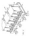
- FIG. 2is a perspective view showing multiple liquid supply containers in loaded positions within a liquid dispenser.
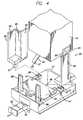
- FIG. 3is an exploded view showing a liquid supply container frame and pre-filled bag in relationship to the support means and clamping means in accordance with the invention.
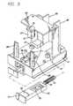
- FIG. 4is an exploded view showing the relationship of a liquid supply container, the adjustable guide means and the clamping means in accordance with the invention.
- FIG. 5is an exploded view of the clamping member for regulating the flow of liquid from the dispenser and the cooling means in accordance with our invention.
- FIG. 6is a partial sectional side view of the clamping member in the closed position.
- FIG. 7is a partial sectional side view showing the relationship of the clamping member and a liquid supply container.
- FIG. 8is a partial sectional side view illustrating the connector of the liquid supply container extending through the clamping member, which is in the open position.
- FIG. 9is a partial sectional side view illustrating the connector of the liquid supply container extending through the clamping member, which is in the closed position.
- FIG. 10is a bottom plan view of the platform of the dispenser.
- FIG. 11is a side elevational view of the platform of the dispenser.
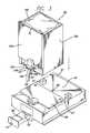
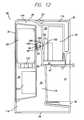
- FIG. 12is a sectional side view of an alternative embodiment of a dispenser in accordance with the invention.
- FIGS. 1 and 2show a preferred embodiment of a liquid dispenser 20 including a housing 22 having a base 24 , a top 26 and two generally vertical opposing side walls 28 .
- a generally vertical partition 30located approximately midway between the front and rear of the housing 22 , extends transversally between the side walls 28 .
- a generally horizontal support shelf 39extends forward from the partition 30 .
- the housing 22defines a rear compartment 34 having an opening in the back of the housing 22 , a liquid storage compartment 32 located in the upper portion of the housing above the shelf 39 opening generally toward the top and front of the housing 22 , and a recess 31 located in the lower portion of the housing 22 below the shelf 39 opening toward the front of the housing 22 .
- the housing 22includes a removable vented panel 35 , which covers the rear compartment 34 .
- a removable drip tray 40is located in the base 24 in the bottom of the recess 31 .
- the housing 22also includes a cover 36 adapted to closely fit the opening of the storage compartment 32 and rotatably attached to the housing top 26 by hinges 37 . In this configuration, the storage compartment 32 is fully enclosed when the cover 36 is in the lowered, closed position. Access to the storage compartment 32 is achieved by lifting the front of the cover 36 thereby rotating the cover 36 on the hinges 37 into an open position.
- a latch 38is adapted to latch the cover 36 in the closed position.
- the housing 22is formed so that the base 24 , the top 26 , the cover 36 , the partition 30 and the support shelf 39 are hollow. Such a construction can be achieved by using a rotational molding process to form the housing 22 , preferably from thermoplastic material such as polyethylene. When so constructed, the interior of the housing can be filled with thermal insulating material 114 , such as a spray foam insulating material.
- a removable platform 41is positioned on top of the support shelf 39 .
- a generally horizontal channel 49is located in the partition 30 and the side walls 28 adjacent the platform 41 for slidingly receiving the rear edge of the platform 41 and restricting the platform from upward movement.
- the platform 41includes a catch basin 42 having an inclined or slanted bottom providing a low drain point and a drain spout 43 which is in overlying relation to the surface of the partition 30 and to a drip tray 40 .
- the platform 41includes at least one upwardly projecting container pedestal 47 for contacting a container bottom wall 46 when the container 45 is in the loaded position. In one preferred embodiment, as shown in FIG.
- the platform 41also includes a plurality of stationary vertical guides 88 and guide means 80 adapted to vertically slidably receive a liquid supply container 45 into a loaded position.
- the platform 41does not use guide means.
- the platform 41is composed of injection molded thermoplastic.
- a clamping member 50having a generally elongated body and a rectangular faced end 51 .
- the clamping member 50is preferably rectangular and made out of plastic, which may be formed by molding, extrusion or any other conventional means known in the art.
- a channel 52extends through the clamping member 50 and is shaped to preferably accommodate either a connector 56 or a cooling member 65 , or both, as described below.
- a flattened rectangular-shaped gate 53extends into the channel 52 from one end. Preferably, the gate 53 extends about halfway into the channel 52 as illustrated in FIG. 5 .
- the clamping member 50is slidably movable along a horizontal axis by any conventional means known in the art, and preferably by a coil spring 54 attached to a pin 55 as illustrated in FIG. 5 .
- a connector 56has an opening end 58 in fluid communication with a discharge end 59 by way of a connecting passage 57 .
- the opening end 58is attached to the container 45 . Liquid flowing from the container flows by gravity through the opening end 58 into the passage 57 and, when the connecting passage 57 is open, out the discharge end 59 of the connector 56 into a vessel 60 , as desired.
- the connector 56is a tube made of a flexible material, such as polyvinylchloride or rubber. The diameter of the connector determines the speed of the liquid flow and is preferably less than one-half inch in diameter.
- the opening end 58is connected to an opening means 61 of the container 45 as is known in the art.
- the opening meansincludes a non-flexible tube (not shown) made of plastic or metal extending from the container 45 .
- the opening end 58 of the connector 56snugly fits over the tube to form an airtight seal. By this means the connector 56 may be easily disconnected from the tube for cleaning and to replace the connector 56 .
- the connector 56extends from the container 45 through the channel 52 of the clamping member 50 , as illustrated in FIG. 5 .
- the clamping member 50controls the flow of the liquid.
- the tension of the compressed coil spring 54urges the gate 53 into the channel 52 to clamp the passage 57 of the connector 56 tightly closed, thereby preventing the gravity flow of the liquid.
- the faced end 51 of the clamping means 50is depressed by a user, as shown in FIG. 8, the spring 54 is compressed further and the gate 53 is disengaged from the connector 56 . This opens the passage 57 and permits the gravity flow of the liquid from the container 45 .
- the liquid retained in the connector 56is cooled by a thermal plate 65 , which is positioned on top of the platform 41 as shown in FIGS. 3 and 4.
- the plate 65is preferably made of a metal material and generally shaped in a rectangular, flat form with a protruding extension 67 , as shown in FIG. 5 .
- the extension 67preferably corresponds in shape to a channel 68 in the platform 41 and extends through the channel 52 of the clamping member 50 .
- a passage 70 extending through the protruding extension 67accommodates the connector 56 so that the connector is pressed against the side of the passage 70 when the clamping member 50 is in the closed position (FIG. 9 ). In this manner, liquid retained in the passage 57 of the connector 56 is cooled by the plate 65 .
- This thermal regulationnot only provides a cooled product, but also aids in preventing any microbial growth in the passage 57 .
- the protruding extension 67 of the thermal plate 65contains a slotted channel 72 which extends a short distance, preferably less than halfway into the extension 67 as illustrated in FIGS. 6 through 9.
- the slotted channel 72is positioned in the same or similar plane as the gate 53 , so that the gate 53 (which extends into the channel 52 of the sliding closure 50 ) correspondingly fits into the slotted channel 72 .
- the coil spring 54holds the gate 53 in a direction toward the slotted channel 72 to clamp or pinch together a portion of the passage 57 of the connector 56 .
- the container 45may be made of any conventional means known in the art, such as a flexible plastic container, a rigid plastic or wax coated paper container, provided that the container is fitted with a connector 56 . A variety of container sizes may be accommodated in the dispenser and held.
- the containermay be a refillable container or it may be a disposable container.
- FIG. 3illustrates one preferred embodiment of the platform 41 and the container 45 .
- the container 45comprises a box-shaped frame 150 for holding a disposable plastic bag or liner 152 that contains liquid to be dispensed.
- the container frame 150preferably includes a slidably removable wall 154 to allow for loading of the plastic bag 152 into the frame 150 .
- the removable wall 154is removed from the frame 150 by sliding it in the direction of arrow A off the frame 150 and is replaced by sliding it onto the frame 150 in a reverse manner.
- the plastic bag 152includes a plastic fitment 156 , as is known in the art, to which the connector 56 is mounted so that the interior of the plastic bag 152 is in fluid communication with the interior of the connector 156 .
- a slot 158 in the bottom of the container frame 150slidingly receives and holds the fitment 156 so than the connector 56 projects below the bottom of the frame 150 .
- FIG. 4illustrates another embodiment of the platform 41 having adjustable guide means to accommodate more than one size of liquid container 45 .
- adjustable guide means 80 having guide posts 81are positioned in openings 82 in the platform 41 .
- the openings 82have a corresponding shape to the guide posts 81 of the guide means 80 .
- the guide means 80contain three generally vertical side walls positioned in such a manner that a center wall 85 is opposing to the two end walls 84 , 86 as illustrated in FIG. 4 .
- This configuration of the guide means 80permits the user to remove the guide means 80 from the platform 41 , turn the guide means 80 and reposition the means 80 in the platform 41 .
- the adjustable guide means 80 together with stationary guide means 88provide the means to change the size of the area to be occupied by the container 45 from a larger volume container to a smaller one and to return to an original configuration.
- An example liquid container and tapping stem suitable for use with this embodimentis disclosed in U.S. Pat. No. 5,855,298, issued to Charles F. Teetsel, III.
- a preferred embodiment of the dispenseris adapted to dispense liquid from a plurality of containers 45 at one time.
- the storage compartment 32is sized to accommodate the plurality of containers 45 .
- the dispenseris adapted to hold a plurality of platforms 41 in the storage compartment 32 .
- the dispenseralso includes a plurality of drain channels 48 , clamping members 50 , cooling pates 65 , connectors 56 , catch basins 42 and drain spouts 43 for providing the structure disclosed above for each of the plurality of containers 45 .
- the embodiment shown in FIG. 2utilizes the platform configuration of FIG. 4 . It will be understood, however, that the platform configuration of FIG. 3 also may be used for any of the plurality of platforms 41 in the storage compartment.
- Temperature control of the storage compartment 32can be provided by any means known in the art.
- temperature control of the storage compartment 32is provided by a conventional hermetic refrigeration system using a compressed gas.
- This systemincludes a compressor 160 mounted in the rear compartment 34 on a compressor support 161 and connected, via a refrigerant line 162 , in fluid communication with evaporator coils 164 mounted in the storage compartment 32 .
- the compressor 160is connected via another refrigerant line 166 to condenser coils 164 mounted in the rear compartment 34 .
- An insulating block 167helps insulate the storage compartment 32 from the rear compartment 34 .
- An evaporator fan 168is mounted in the storage compartment 132 adjacent the evaporator coils 164 to circulate air in the storage compartment 32 over the evaporator coils 164 .
- a condenser fan 169is mounted in the rear compartment 34 adjacent the condenser coils 164 and is adapted to circulate external air over the condenser coils 164 .
- the compressor 160includes a power supply that provides electric power to operate the evaporator fan 168 and the condenser fan 169 as well as the compresser itself.
- a thermostat 170includes a control mechanism 172 located outside of the storage compartment in any suitable location that is accessible to the user.
- the thermostat 170also includes a temperature sensor 174 , which is located inside the storage compartment 32 and is coupled to the control mechanism 172 via coupling line 176 .
- the thermostat 170is a solid state thermostat.
- One suitable refrigeration systemhas been provided by Blissfield Manufacturing Co., of Blissfield, Mich.
- the refrigerant line 162 and the temperature sensor coupling line 176are closely fitted through a channel in the insulating block 167 that extends between the storage compartment 32 and the rear compartment 34 .
- the insulating blockis made of an insulating material in which it is easy to form such a channel, such as Styrofoam.
- the temperature of the storage compartment 32can be controlled by the thermostat control 172 .
- Temperature control of the storage compartment 32also is improved by providing thermal insulation 114 in the interior of the base 24 , the top 26 , the cover 36 and the partition 30 of the housing 22 , as discussed above.
- FIG. 12illustrates an embodiment of a dispenser in which temperature control is provided by means including a thermoelectric module 90 adapted to enable transfer of thermal energy between the storage compartment 32 and the external environment of the liquid dispenser 20 .
- a cold plate 92is mounted inside the storage compartment 32 on the partition 30
- a heat sink 96is mounted inside the rear compartment 34 on the partition 30 .
- the cold plate 92is positioned in overlying relation to the catch basin 42 for collecting condensation from the cold plate.
- thermoelectric module 90A hot side 94 of the thermoelectric module 90 is thermally coupled to the heat sink 96 , and a cold side 93 of the thermoelectric module 90 is thermally coupled to a thermal transfer block 98 , which is closely positioned within a shaft 100 extending through the partition 30 and is also thermally coupled to the cold plate 92 .
- the cold plate 92 , the thermal transfer block 98 , and the heat sink 96are composed of material having suitable thermal conductivity, preferably aluminum or copper. Thermal coupling of these elements is enhanced by applying a thermally conductive medium 102 , such as thermal epoxy, thermal grease or thermal pads between the surfaces of the elements where they interface each other and the thermoelectric module 90 .
- a fan 110is mounted in the rear compartment 34 adjacent the heat sink 96 and is adapted to move air over the heat sink 96 .
- a power supply 112provides electric power to operate the fan 110 and the thermoelectric module 90 .
- the temperature of the storage compartment 32can be controlled by regulating the power to the thermoelectric module 90 using conventional means, preferably a thermistor mounted in the cold plate 92 , a feedback loop and power supply control circuitry. Temperature control of the storage compartment 32 is improved by providing thermal insulation 114 in the interior of the base 24 , the top 26 , the cover 36 and the partition 30 of the housing 22 , as discussed above. The desired temperature control may be achieved with only one thermoelectric module 90 . Alternatively, multiple thermoelectric modules 90 can be used for improved thermal transfer capacity.
- a container of liquid 45is loaded into the dispenser 20 by moving the container 45 downward into contacting relation with the container pedestals 47 of the platform 41 .
- connector 56will extend through the channel 68 of the platform 41 , out the cooling plate 65 and through the channel 52 of the sliding closure forming a communication from the interior of the container 45 to a vessel 60 to receive the liquid.
- the upper end of the container 45is opened or punctured to allow entry of air into the container 45 to enable the liquid to flow freely when dispensed.
- the container 45 shown in FIG. 4is loaded by positioning the container 45 within the guides 88 and adjustable guide means 80 and by moving the container 45 downward into contacting relation with the container pedestals 47 of the platform 41 .
- liquidis dispensed from the container 45 and out of the connector 56 by pushing the clamping means 50 toward the dispenser 20 to coil the spring 54 causing the gate end 54 of the gate 53 to release the pressure on the connector 56 , thereby allowing gravitational flow of liquid from the container 45 through the connector 56 to the vessel 60 .
- the coil spring 54uncoils causing the gate end 54 to compress the connector 56 and restrict the flow of liquid.
- the container 45is empty, it can be removed by horizontally sliding the clamping means 50 away from the dispenser 20 and removing the container 45 and the connector 56 attached thereto, from the platform 41 .
- the platform 41 , the connector 56 and the clamping means 50may be removed from the housing 22 and disassembled.
- the connector 56may be disposed of, rather than cleaned, and replaced with a connector 56 .
- the above-described structurepossesses several advantages. It is convenient to use and clean because, among other reasons, the liquid dispenser can utilize disposable containers, the platform 41 , the connector 56 , and the clamping means 50 can be easily dissasembled for cleaning and the connector 56 can be disposable. Generally, only the container 45 and the connector 56 , both of which can be disposable, come into extensive contact with the liquid, thereby reducing cleaning and maintenance requirements.
- the dispensercan be constructed of relatively inexpensive materials.
- the disclosed dispenser structureis compact in size and can dispense liquid from multiple containers at one time.
- the liquid dispenser, the thermoelectric module 90 and associated elementsmay be configured to heat the storage compartment 32 , rather than cool it.
- the storage compartment 32may be cooled by providing a eutectic cooling device removably mounted inside the storage compartment 32 as the temperature control means. Therefore, the spirit and scope of the appended claims should not necessarily be limited to the exact construction and operation shown and described, and accordingly, all suitable modifications and equivalents may be resorted to, falling within the scope of the invention.
Landscapes
- Engineering & Computer Science (AREA)
- Mechanical Engineering (AREA)
- Devices For Dispensing Beverages (AREA)
Abstract
Description
Claims (16)
Priority Applications (2)
| Application Number | Priority Date | Filing Date | Title |
|---|---|---|---|
| US09/510,936US6186361B1 (en) | 1994-08-18 | 2000-02-22 | Liquid dispenser |
| US09/767,540US6497343B1 (en) | 1994-08-18 | 2001-01-23 | Liquid dispenser with sliding flow regulator |
Applications Claiming Priority (4)
| Application Number | Priority Date | Filing Date | Title |
|---|---|---|---|
| US29273294A | 1994-08-18 | 1994-08-18 | |
| US08/811,135US5855298A (en) | 1994-08-18 | 1997-03-03 | Tapping stem for liquid supply container |
| US09/225,257US6026988A (en) | 1994-08-18 | 1999-01-04 | Liquid dispenser with tapping stem |
| US09/510,936US6186361B1 (en) | 1994-08-18 | 2000-02-22 | Liquid dispenser |
Related Parent Applications (1)
| Application Number | Title | Priority Date | Filing Date |
|---|---|---|---|
| US09/225,257Continuation-In-PartUS6026988A (en) | 1994-08-18 | 1999-01-04 | Liquid dispenser with tapping stem |
Related Child Applications (1)
| Application Number | Title | Priority Date | Filing Date |
|---|---|---|---|
| US09/767,540DivisionUS6497343B1 (en) | 1994-08-18 | 2001-01-23 | Liquid dispenser with sliding flow regulator |
Publications (1)
| Publication Number | Publication Date |
|---|---|
| US6186361B1true US6186361B1 (en) | 2001-02-13 |
Family
ID=27397461
Family Applications (2)
| Application Number | Title | Priority Date | Filing Date |
|---|---|---|---|
| US09/510,936Expired - LifetimeUS6186361B1 (en) | 1994-08-18 | 2000-02-22 | Liquid dispenser |
| US09/767,540Expired - LifetimeUS6497343B1 (en) | 1994-08-18 | 2001-01-23 | Liquid dispenser with sliding flow regulator |
Family Applications After (1)
| Application Number | Title | Priority Date | Filing Date |
|---|---|---|---|
| US09/767,540Expired - LifetimeUS6497343B1 (en) | 1994-08-18 | 2001-01-23 | Liquid dispenser with sliding flow regulator |
Country Status (1)
| Country | Link |
|---|---|
| US (2) | US6186361B1 (en) |
Cited By (43)
| Publication number | Priority date | Publication date | Assignee | Title |
|---|---|---|---|---|
| US6370884B1 (en)* | 2001-03-30 | 2002-04-16 | Maher I. Kelada | Thermoelectric fluid cooling cartridge |
| US6497343B1 (en) | 1994-08-18 | 2002-12-24 | Teetsel, Iii Charles F. | Liquid dispenser with sliding flow regulator |
| US20030017066A1 (en)* | 2001-07-19 | 2003-01-23 | Baxter International Inc. | Apparatus, flexible bag and method for dispensing |
| US6516976B2 (en) | 2000-12-19 | 2003-02-11 | Kimberly-Clark Worldwide, Inc. | Dosing pump for liquid dispensers |
| US6533145B2 (en) | 2000-12-19 | 2003-03-18 | Kimberly-Clark Worldwide, Inc. | Self-contained viscous liquid dispenser |
| US6540117B2 (en) | 2001-03-30 | 2003-04-01 | Kimberly-Clark Worldwide, Inc. | Dosing pump for liquid dispensers |
| US20040099689A1 (en)* | 2002-09-23 | 2004-05-27 | Almond Kelly George | Liquid dispensing apparatus |
| US20040144800A1 (en)* | 2003-01-24 | 2004-07-29 | Baxter International, Inc. | Liquid dispenser and flexible bag therefor |
| US20040144799A1 (en)* | 2003-01-24 | 2004-07-29 | Baxter International Inc. | Liquid dispenser and flexible bag therefor |
| US6769231B2 (en) | 2001-07-19 | 2004-08-03 | Baxter International, Inc. | Apparatus, method and flexible bag for use in manufacturing |
| US20040211718A1 (en)* | 2000-02-16 | 2004-10-28 | Tsuneo Deguchi | Apparatus for preparing a dialyzate and a powder dialysis preparation |
| WO2004094295A1 (en)* | 2003-04-24 | 2004-11-04 | Harrogate Spa Water Ltd | Storage box for a flexible liquid-containing bag |
| US20050011908A1 (en)* | 2003-07-16 | 2005-01-20 | Baxter International, Inc. | Dispenser and pressure/vacuum converting machine |
| US6863644B1 (en) | 2001-08-24 | 2005-03-08 | Lbp Manufacturing, Inc. | Beverage container holder |
| US6905314B2 (en) | 2001-10-16 | 2005-06-14 | Baxter International Inc. | Pump having flexible liner and compounding apparatus having such a pump |
| US20060025189A1 (en)* | 2004-07-30 | 2006-02-02 | Igt | Stud bingo |
| US20060132247A1 (en)* | 2004-12-20 | 2006-06-22 | Renesas Technology Corp. | Oscillator and charge pump circuit using the same |
| US20060138164A1 (en)* | 2003-07-03 | 2006-06-29 | Goepfert Gerard F | Under counter dispenser |
| US20060180611A1 (en)* | 2005-01-19 | 2006-08-17 | Goepfert Gerard F | Systems and methods for dispensing controlled portions |
| US20070089231A1 (en)* | 2005-10-24 | 2007-04-26 | Fendall, Inc. | Emergency eyewash station having a peircing mechanism to puncture a sealed fluid bladder |
| US20070092388A1 (en)* | 2005-10-24 | 2007-04-26 | Fendall, Inc. | Pump assembly for an emergency eyewash station |
| US20070089232A1 (en)* | 2005-10-24 | 2007-04-26 | Fendall, Inc. | Cartridge assembly for a self-contained emergency eyewash station |
| US20070089233A1 (en)* | 2005-10-24 | 2007-04-26 | Fendall, Inc. | Emergency eyewash station having an expandable bellows waste collection system |
| US20070089234A1 (en)* | 2005-10-24 | 2007-04-26 | Fendall, Inc. | Emergency eyewash station having an integrated head rest |
| AT502593B1 (en)* | 2005-04-21 | 2007-08-15 | Karadar Diether | BEVERAGE DISPENSER |
| US20070219511A1 (en)* | 2006-03-15 | 2007-09-20 | Fendall, Inc. | Emergency eyewash station and dispensing structure therefor |
| US20110036864A1 (en)* | 2007-11-07 | 2011-02-17 | Aqueduct Investments International Ltd. | System and Method for Containing and Dispensing a Liquid |
| US8040266B2 (en) | 2007-04-17 | 2011-10-18 | Cypress Semiconductor Corporation | Programmable sigma-delta analog-to-digital converter |
| US20120326061A1 (en)* | 2011-06-27 | 2012-12-27 | Prince Castle LLC | Pinch Bar |
| US8376310B2 (en) | 2010-09-20 | 2013-02-19 | Prince Castle, LLC | Pinch valve |
| US8534497B2 (en) | 2010-09-20 | 2013-09-17 | Prince Castle, LLC | Dispensing method and apparatus utilizing a sensor to determine a time that a dispensing valve is open |
| US8636176B2 (en) | 2011-06-27 | 2014-01-28 | Prince Castle, LLC | Liquid dispenser pinch valve |
| US8636180B2 (en) | 2011-06-27 | 2014-01-28 | Prince Castle, LLC | Pinch valve |
| US20140252031A1 (en)* | 2013-03-05 | 2014-09-11 | The Coca-Cola Company | Beverage Dispensing System |
| US8844768B2 (en) | 2011-06-27 | 2014-09-30 | Prince Castle LLC | Liquid dispenser with storage tanks |
| US20150129612A1 (en)* | 2013-11-06 | 2015-05-14 | Scholle Corporation | Dispensing Bag Having A Hose Spout |
| US9079728B2 (en) | 2012-09-12 | 2015-07-14 | Lbp Manufacturing, Inc. | Feeder system for beverage container holder process |
| US9714110B2 (en) | 2012-03-23 | 2017-07-25 | Prince Castle LLC | Holding tank with internally reinforced sidewalls and liquid dispenser using same |
| US9988257B2 (en) | 2015-12-21 | 2018-06-05 | Prince Castle LLC | Manual dispensing valve |
| US10427178B2 (en)* | 2014-12-22 | 2019-10-01 | Cyclonas Pty Limited | Pressurised liquid delivery system |
| US10926990B2 (en)* | 2016-12-16 | 2021-02-23 | Lg Electronics Inc. | Liquid dispensor |
| US11091362B2 (en)* | 2017-05-11 | 2021-08-17 | Grabas Limited | Gravity fed viscous liquid and food product dispensing system |
| US11383966B1 (en)* | 2021-03-17 | 2022-07-12 | Electrolux Home Products, Inc. | Fluid dispenser with anti-run-on |
Families Citing this family (12)
| Publication number | Priority date | Publication date | Assignee | Title |
|---|---|---|---|---|
| ITPN20050069A1 (en)* | 2005-10-06 | 2007-04-07 | Electrolux Professional Spa | REFRIGERATOR UNIT FOR THE COOLING OF PRESSURIZED DRINKS |
| WO2008071024A1 (en)* | 2006-12-12 | 2008-06-19 | Jura Elektroapparate Ag | Beverage preparation machine with a pinch valve |
| US8459503B2 (en)* | 2007-05-10 | 2013-06-11 | R. Clay Groesbeck | Temperature controlled liquid dispenser, containers therefore, and bag-in-box container construction |
| KR100900292B1 (en)* | 2007-07-05 | 2009-05-29 | 엘지전자 주식회사 | Food storage equipment and control method |
| KR101405931B1 (en)* | 2007-07-06 | 2014-06-12 | 엘지전자 주식회사 | Food storage device and control method thereof |
| KR101405932B1 (en)* | 2007-07-06 | 2014-06-12 | 엘지전자 주식회사 | Food storage equipment |
| KR101396973B1 (en)* | 2007-07-06 | 2014-05-20 | 엘지전자 주식회사 | Refrigerator and Controlling method for the same |
| US8690016B2 (en)* | 2009-09-21 | 2014-04-08 | Imi Cornelius Inc. | Product storage and handling system for beverage dispenser |
| US8800817B2 (en)* | 2010-12-06 | 2014-08-12 | The Coca-Cola Company | Beverage dispensing device |
| EP2651270B1 (en) | 2010-12-16 | 2017-02-15 | Briggo, LLC | Apparatus and method for brewed and espresso drink generation |
| WO2013055938A1 (en)* | 2011-10-11 | 2013-04-18 | Briggo, Inc. | Apparatus and method for networked drink making and dispensing machine |
| US10043226B2 (en) | 2014-07-22 | 2018-08-07 | Briggo, Inc. | Facilitating beverage ordering and generation |
Citations (10)
| Publication number | Priority date | Publication date | Assignee | Title |
|---|---|---|---|---|
| US2831610A (en)* | 1956-09-13 | 1958-04-22 | Chase Bag Company | Liquid dispensing container |
| US2895653A (en)* | 1957-06-27 | 1959-07-21 | American Nat Bank | Measuring and dispensing valve |
| US3035737A (en)* | 1960-02-12 | 1962-05-22 | Hedwin Corp | Liquid container dispensing rack |
| US3212681A (en)* | 1963-10-09 | 1965-10-19 | Gen Films Inc | Container structure |
| US3358883A (en)* | 1966-03-21 | 1967-12-19 | Loe Ind | Piercing and venting means for cans |
| US4341328A (en)* | 1980-01-30 | 1982-07-27 | Redick Jr Richard W | Adapter for bottled water dispenser |
| US4557399A (en)* | 1980-01-30 | 1985-12-10 | Redick Jr Richard W | Adapter for bottled water dispenser |
| US4907723A (en)* | 1986-03-10 | 1990-03-13 | Solly Katz | Fluid dispenser including an arrangement to impart wave-like motion to the store fluid |
| US5855298A (en)* | 1994-08-18 | 1999-01-05 | Creamiser Products Corporation | Tapping stem for liquid supply container |
| US5938078A (en)* | 1997-05-09 | 1999-08-17 | Stevens-Lee Company | Valve for beverage dispenser |
Family Cites Families (10)
| Publication number | Priority date | Publication date | Assignee | Title |
|---|---|---|---|---|
| US3445039A (en)* | 1966-10-31 | 1969-05-20 | Progressive Metal Equipment In | Liquid dispenser with timer control |
| US4634092A (en)* | 1984-09-30 | 1987-01-06 | Fisher & Paykel, Private Bag | Clamp valves |
| US4673109A (en)* | 1985-10-18 | 1987-06-16 | Steiner Company, Inc. | Liquid soap dispensing system |
| US5105981A (en)* | 1990-11-19 | 1992-04-21 | Thomas Gehman | Selectively shakeable freestanding particulate matter reservoir |
| JPH0725489Y2 (en)* | 1990-11-24 | 1995-06-07 | 株式会社堀場製作所 | Pinch valve |
| US5439145A (en) | 1992-07-17 | 1995-08-08 | Ebac Limited | Apparatus for dispensing liquid from an inverted container |
| US6186361B1 (en) | 1994-08-18 | 2001-02-13 | Creamiser Products Corporation | Liquid dispenser |
| US5625659A (en)* | 1995-05-19 | 1997-04-29 | Gojo Industries, Inc. | Method and apparatus for electronically measuring dispenser usage |
| USD391971S (en) | 1996-05-17 | 1998-03-10 | Stevens-Lee Company | Refrigerated milk dispenser |
| USD386049S (en) | 1996-05-17 | 1997-11-11 | Stevens-Lee Company | Milk bag holder for a milk dispenser |
- 2000
- 2000-02-22USUS09/510,936patent/US6186361B1/ennot_activeExpired - Lifetime
- 2001
- 2001-01-23USUS09/767,540patent/US6497343B1/ennot_activeExpired - Lifetime
Patent Citations (11)
| Publication number | Priority date | Publication date | Assignee | Title |
|---|---|---|---|---|
| US2831610A (en)* | 1956-09-13 | 1958-04-22 | Chase Bag Company | Liquid dispensing container |
| US2895653A (en)* | 1957-06-27 | 1959-07-21 | American Nat Bank | Measuring and dispensing valve |
| US3035737A (en)* | 1960-02-12 | 1962-05-22 | Hedwin Corp | Liquid container dispensing rack |
| US3212681A (en)* | 1963-10-09 | 1965-10-19 | Gen Films Inc | Container structure |
| US3358883A (en)* | 1966-03-21 | 1967-12-19 | Loe Ind | Piercing and venting means for cans |
| US4341328A (en)* | 1980-01-30 | 1982-07-27 | Redick Jr Richard W | Adapter for bottled water dispenser |
| US4557399A (en)* | 1980-01-30 | 1985-12-10 | Redick Jr Richard W | Adapter for bottled water dispenser |
| US4907723A (en)* | 1986-03-10 | 1990-03-13 | Solly Katz | Fluid dispenser including an arrangement to impart wave-like motion to the store fluid |
| US5855298A (en)* | 1994-08-18 | 1999-01-05 | Creamiser Products Corporation | Tapping stem for liquid supply container |
| US6026988A (en)* | 1994-08-18 | 2000-02-22 | Creamiser Products Corporation | Liquid dispenser with tapping stem |
| US5938078A (en)* | 1997-05-09 | 1999-08-17 | Stevens-Lee Company | Valve for beverage dispenser |
Cited By (73)
| Publication number | Priority date | Publication date | Assignee | Title |
|---|---|---|---|---|
| US6497343B1 (en) | 1994-08-18 | 2002-12-24 | Teetsel, Iii Charles F. | Liquid dispenser with sliding flow regulator |
| US20040211718A1 (en)* | 2000-02-16 | 2004-10-28 | Tsuneo Deguchi | Apparatus for preparing a dialyzate and a powder dialysis preparation |
| US6575334B2 (en) | 2000-12-19 | 2003-06-10 | Kimberly-Clark Worldwide, Inc. | Self-contained viscous liquid dispenser |
| US6648179B2 (en) | 2000-12-19 | 2003-11-18 | Kimberly-Clark Worldwide, Inc. | Self-contained viscous liquid dispenser |
| US6533145B2 (en) | 2000-12-19 | 2003-03-18 | Kimberly-Clark Worldwide, Inc. | Self-contained viscous liquid dispenser |
| US6729502B2 (en) | 2000-12-19 | 2004-05-04 | Kimberly-Clark Worldwide, Inc. | Self-contained viscous liquid dispenser |
| US6543651B2 (en) | 2000-12-19 | 2003-04-08 | Kimberly-Clark Worldwide, Inc. | Self-contained viscous liquid dispenser |
| US6575335B2 (en) | 2000-12-19 | 2003-06-10 | Kimberly-Clark Worldwide, Inc. | Self-contained viscous liquid dispenser |
| US6516976B2 (en) | 2000-12-19 | 2003-02-11 | Kimberly-Clark Worldwide, Inc. | Dosing pump for liquid dispensers |
| US6540117B2 (en) | 2001-03-30 | 2003-04-01 | Kimberly-Clark Worldwide, Inc. | Dosing pump for liquid dispensers |
| US6370884B1 (en)* | 2001-03-30 | 2002-04-16 | Maher I. Kelada | Thermoelectric fluid cooling cartridge |
| US20040094573A1 (en)* | 2001-07-19 | 2004-05-20 | Baxter International Inc. | Flow control apparatus for use in dispensing fluent material |
| US6769231B2 (en) | 2001-07-19 | 2004-08-03 | Baxter International, Inc. | Apparatus, method and flexible bag for use in manufacturing |
| US20030017066A1 (en)* | 2001-07-19 | 2003-01-23 | Baxter International Inc. | Apparatus, flexible bag and method for dispensing |
| US6863644B1 (en) | 2001-08-24 | 2005-03-08 | Lbp Manufacturing, Inc. | Beverage container holder |
| US6905314B2 (en) | 2001-10-16 | 2005-06-14 | Baxter International Inc. | Pump having flexible liner and compounding apparatus having such a pump |
| US20040099689A1 (en)* | 2002-09-23 | 2004-05-27 | Almond Kelly George | Liquid dispensing apparatus |
| US7021496B2 (en)* | 2002-09-23 | 2006-04-04 | Kelly George Almond | Liquid dispensing apparatus |
| US20040144799A1 (en)* | 2003-01-24 | 2004-07-29 | Baxter International Inc. | Liquid dispenser and flexible bag therefor |
| US7007824B2 (en) | 2003-01-24 | 2006-03-07 | Baxter International Inc. | Liquid dispenser and flexible bag therefor |
| US7237691B2 (en) | 2003-01-24 | 2007-07-03 | Baxter International Inc. | Flexible bag for fluent material dispenser |
| US20040144800A1 (en)* | 2003-01-24 | 2004-07-29 | Baxter International, Inc. | Liquid dispenser and flexible bag therefor |
| WO2004094295A1 (en)* | 2003-04-24 | 2004-11-04 | Harrogate Spa Water Ltd | Storage box for a flexible liquid-containing bag |
| GB2417721A (en)* | 2003-04-24 | 2006-03-08 | Harrogate Spa Water Ltd | Storage box for a flexible liquid-containing bag |
| US20060138164A1 (en)* | 2003-07-03 | 2006-06-29 | Goepfert Gerard F | Under counter dispenser |
| US20070056985A9 (en)* | 2003-07-03 | 2007-03-15 | Goepfert Gerard F | Under counter dispenser |
| US7360670B2 (en) | 2003-07-03 | 2008-04-22 | Creamiser Products Corporation | Under counter dispenser |
| US20050011908A1 (en)* | 2003-07-16 | 2005-01-20 | Baxter International, Inc. | Dispenser and pressure/vacuum converting machine |
| US20060025189A1 (en)* | 2004-07-30 | 2006-02-02 | Igt | Stud bingo |
| US20060132247A1 (en)* | 2004-12-20 | 2006-06-22 | Renesas Technology Corp. | Oscillator and charge pump circuit using the same |
| US20060180611A1 (en)* | 2005-01-19 | 2006-08-17 | Goepfert Gerard F | Systems and methods for dispensing controlled portions |
| AT502593B1 (en)* | 2005-04-21 | 2007-08-15 | Karadar Diether | BEVERAGE DISPENSER |
| US8316477B2 (en) | 2005-10-24 | 2012-11-27 | Sperian Eye & Face Protection, Inc. | Cartridge assembly for a self-contained emergency eyewash station |
| US20070089235A1 (en)* | 2005-10-24 | 2007-04-26 | Fendall, Inc. | Pump assembly for an emergency eyewash station |
| US20070089234A1 (en)* | 2005-10-24 | 2007-04-26 | Fendall, Inc. | Emergency eyewash station having an integrated head rest |
| US20070089232A1 (en)* | 2005-10-24 | 2007-04-26 | Fendall, Inc. | Cartridge assembly for a self-contained emergency eyewash station |
| US20070092388A1 (en)* | 2005-10-24 | 2007-04-26 | Fendall, Inc. | Pump assembly for an emergency eyewash station |
| US20070089233A1 (en)* | 2005-10-24 | 2007-04-26 | Fendall, Inc. | Emergency eyewash station having an expandable bellows waste collection system |
| US20070089231A1 (en)* | 2005-10-24 | 2007-04-26 | Fendall, Inc. | Emergency eyewash station having a peircing mechanism to puncture a sealed fluid bladder |
| US8435220B2 (en) | 2005-10-24 | 2013-05-07 | Sperian Eye and Face Protection, Inc. a Delaware corporation | Emergency eyewash station having an expandable bellows waste collection system |
| US20110046582A1 (en)* | 2005-10-24 | 2011-02-24 | Sperian Eye & Face Protection, Inc | Retrofit kit and method of retrofitting a plumbed emergency eyewash station |
| US8371825B2 (en) | 2005-10-24 | 2013-02-12 | Sperian Eye & Face Protection, Inc. | Retrofit kit and method of retrofitting a plumbed emergency eyewash station |
| US8205279B2 (en) | 2005-10-24 | 2012-06-26 | Sperian Eye & Face Protection, Inc. | Pump assembly for an emergency eyewash station |
| US20070219511A1 (en)* | 2006-03-15 | 2007-09-20 | Fendall, Inc. | Emergency eyewash station and dispensing structure therefor |
| US8313472B2 (en) | 2006-03-15 | 2012-11-20 | Sperian Eye & Face Protection, Inc. a Delaware corporation | Emergency eyewash station and dispensing structure therefor |
| US8040266B2 (en) | 2007-04-17 | 2011-10-18 | Cypress Semiconductor Corporation | Programmable sigma-delta analog-to-digital converter |
| US10384849B2 (en)* | 2007-11-07 | 2019-08-20 | Aqueduct Invest Ltd. | System and method for containing and dispensing a liquid |
| US20110036864A1 (en)* | 2007-11-07 | 2011-02-17 | Aqueduct Investments International Ltd. | System and Method for Containing and Dispensing a Liquid |
| US20160060012A1 (en)* | 2007-11-07 | 2016-03-03 | Aqueduct Invest Ltd. | System and Method for Containing and Dispensing a Liquid |
| US8376310B2 (en) | 2010-09-20 | 2013-02-19 | Prince Castle, LLC | Pinch valve |
| US8534497B2 (en) | 2010-09-20 | 2013-09-17 | Prince Castle, LLC | Dispensing method and apparatus utilizing a sensor to determine a time that a dispensing valve is open |
| US9533869B2 (en) | 2010-09-20 | 2017-01-03 | Prince Castle LLC | Pinch valve for dispenser for liquids |
| US9174834B2 (en) | 2010-09-20 | 2015-11-03 | Prince Castle LLC | Apparatus and method for dispensing user-specified fixed volumes of liquids |
| US9212042B2 (en) | 2010-09-20 | 2015-12-15 | Prince Castle LLC | Apparatus and method for dispensing liquids using a table to determine dispense time |
| US8727304B2 (en)* | 2011-06-27 | 2014-05-20 | Prince Castle, LLC. | Pinch bar |
| US8636176B2 (en) | 2011-06-27 | 2014-01-28 | Prince Castle, LLC | Liquid dispenser pinch valve |
| US20120326061A1 (en)* | 2011-06-27 | 2012-12-27 | Prince Castle LLC | Pinch Bar |
| US9027791B2 (en) | 2011-06-27 | 2015-05-12 | Prince Castle LLC | Liquid dispenser with storage tanks |
| US9346661B2 (en) | 2011-06-27 | 2016-05-24 | Prince Castle LLC | Liquid dispenser with storage tanks |
| US8844768B2 (en) | 2011-06-27 | 2014-09-30 | Prince Castle LLC | Liquid dispenser with storage tanks |
| US8636180B2 (en) | 2011-06-27 | 2014-01-28 | Prince Castle, LLC | Pinch valve |
| US9714110B2 (en) | 2012-03-23 | 2017-07-25 | Prince Castle LLC | Holding tank with internally reinforced sidewalls and liquid dispenser using same |
| US9079728B2 (en) | 2012-09-12 | 2015-07-14 | Lbp Manufacturing, Inc. | Feeder system for beverage container holder process |
| US9676570B2 (en) | 2012-09-12 | 2017-06-13 | Lbp Manufacturing Llc | Feeder system for beverage container holder process |
| US20140252031A1 (en)* | 2013-03-05 | 2014-09-11 | The Coca-Cola Company | Beverage Dispensing System |
| US9045260B2 (en)* | 2013-03-05 | 2015-06-02 | The Coca-Cola Company | Beverage dispensing system |
| US9745112B2 (en)* | 2013-11-06 | 2017-08-29 | Scholle Ipn Corporation | Dispensing bag having a hose spout |
| US20150129612A1 (en)* | 2013-11-06 | 2015-05-14 | Scholle Corporation | Dispensing Bag Having A Hose Spout |
| US10427178B2 (en)* | 2014-12-22 | 2019-10-01 | Cyclonas Pty Limited | Pressurised liquid delivery system |
| US9988257B2 (en) | 2015-12-21 | 2018-06-05 | Prince Castle LLC | Manual dispensing valve |
| US10926990B2 (en)* | 2016-12-16 | 2021-02-23 | Lg Electronics Inc. | Liquid dispensor |
| US11091362B2 (en)* | 2017-05-11 | 2021-08-17 | Grabas Limited | Gravity fed viscous liquid and food product dispensing system |
| US11383966B1 (en)* | 2021-03-17 | 2022-07-12 | Electrolux Home Products, Inc. | Fluid dispenser with anti-run-on |
Also Published As
| Publication number | Publication date |
|---|---|
| US6497343B1 (en) | 2002-12-24 |
Similar Documents
| Publication | Publication Date | Title |
|---|---|---|
| US6186361B1 (en) | Liquid dispenser | |
| US6026988A (en) | Liquid dispenser with tapping stem | |
| US7062937B1 (en) | Product dispenser | |
| US7975881B1 (en) | Beverage dispenser | |
| CN101146737B (en) | Beverage dispenser | |
| EP1118582B1 (en) | Bottled liquid dispenser | |
| US5857596A (en) | Water dispenser of a refrigerator | |
| US8066152B2 (en) | Liquid cooling and dispensing device | |
| JP2010526738A (en) | Temperature-controlled liquid dispenser, temperature-controlled liquid dispenser container, and bag-in-box container structure | |
| US5743106A (en) | Water dispenser of a refrigerator | |
| US3811294A (en) | Cooler for faucet-equipped beverage containers | |
| US5862952A (en) | Water dispenser of a refrigerator | |
| US5771709A (en) | Electric counter mounted beverage cooler and dispenser | |
| EP3969407B1 (en) | Product dispensing system and method | |
| US3790032A (en) | Party keg beer dispenser apparatus | |
| CA2294965A1 (en) | Beverage dispenser | |
| EP1236675B1 (en) | Bottled liquid dispensers | |
| KR101489874B1 (en) | Portable temperature controlled container | |
| KR100217047B1 (en) | Refrigerator water supply | |
| KR100217048B1 (en) | Water feeding device of refrigerator | |
| KR100307867B1 (en) | A self-cooling container | |
| JP2548463Y2 (en) | Beverage spout spout | |
| JP2001328697A (en) | Beer server | |
| WO2004101425A2 (en) | Drink dispenser with a columnar chill chamber | |
| WO2018076079A1 (en) | A universal device for an active cooling or heating and dispensing of foods from spray cans |
Legal Events
| Date | Code | Title | Description |
|---|---|---|---|
| FEPP | Fee payment procedure | Free format text:PAYOR NUMBER ASSIGNED (ORIGINAL EVENT CODE: ASPN); ENTITY STATUS OF PATENT OWNER: LARGE ENTITY | |
| AS | Assignment | Owner name:CREAMISER PRODUCTS CORPORATION, ARIZONA Free format text:ASSIGNMENT OF ASSIGNORS INTEREST;ASSIGNOR:TEETSEL, III, CHARLES F.;REEL/FRAME:011336/0857 Effective date:20001207 | |
| STCF | Information on status: patent grant | Free format text:PATENTED CASE | |
| FPAY | Fee payment | Year of fee payment:4 | |
| FPAY | Fee payment | Year of fee payment:8 | |
| AS | Assignment | Owner name:JPMORGAN CHASE BANK, NATIONAL ASSOCIATION, AS ADMI Free format text:SECURITY AGREEMENT;ASSIGNOR:CREAMISER PRODUCTS CORPORATION;REEL/FRAME:022510/0276 Effective date:20090228 | |
| AS | Assignment | Owner name:WHITEWAVE FOODS COMPANY,TEXAS Free format text:MERGER;ASSIGNOR:CREAMISER PRODUCTS CORPORATION;REEL/FRAME:024185/0208 Effective date:20090831 Owner name:WHITEWAVE FOODS COMPANY, TEXAS Free format text:MERGER;ASSIGNOR:CREAMISER PRODUCTS CORPORATION;REEL/FRAME:024185/0208 Effective date:20090831 | |
| AS | Assignment | Owner name:WHITEWAVE SERVICES, INC.,TEXAS Free format text:ASSIGNMENT OF ASSIGNORS INTEREST;ASSIGNOR:WHITEWAVE FOODS COMPANY;REEL/FRAME:024225/0036 Effective date:20100409 Owner name:WHITEWAVE SERVICES, INC., TEXAS Free format text:ASSIGNMENT OF ASSIGNORS INTEREST;ASSIGNOR:WHITEWAVE FOODS COMPANY;REEL/FRAME:024225/0036 Effective date:20100409 | |
| FEPP | Fee payment procedure | Free format text:PAT HOLDER NO LONGER CLAIMS SMALL ENTITY STATUS, ENTITY STATUS SET TO UNDISCOUNTED (ORIGINAL EVENT CODE: STOL); ENTITY STATUS OF PATENT OWNER: LARGE ENTITY | |
| FPAY | Fee payment | Year of fee payment:12 | |
| AS | Assignment | Owner name:BANK OF AMERICA, N.A., AS ADMINISTRATIVE AGENT, NO Free format text:NOTICE OF GRANT OF SECURITY INTEREST IN PATENTS;ASSIGNOR:WHITEWAVE SERVICES, INC.;REEL/FRAME:029244/0939 Effective date:20121031 Owner name:WHITEWAVE SERVICES, INC. (INCLUDING AS SUCCESSOR I Free format text:TERMINATION AND RELEASE OF SECURITY INTEREST IN PATENTS;ASSIGNOR:JPMORGAN CHASE BANK, NATIONAL ASSOCIATION, AS ADMINISTRATIVE AGENT;REEL/FRAME:029244/0962 Effective date:20121031 | |
| AS | Assignment | Owner name:WHITEWAVE SERVICES, INC., COLORADO Free format text:RELEASE BY SECURED PARTY;ASSIGNOR:BANK OF AMERICA, N.A., AS ADMINISTRATIVE AGENT;REEL/FRAME:041984/0294 Effective date:20170412 |