US6186290B1 - Magnetorheological brake with integrated flywheel - Google Patents
Magnetorheological brake with integrated flywheelDownload PDFInfo
- Publication number
- US6186290B1 US6186290B1US08/958,660US95866097AUS6186290B1US 6186290 B1US6186290 B1US 6186290B1US 95866097 AUS95866097 AUS 95866097AUS 6186290 B1US6186290 B1US 6186290B1
- Authority
- US
- United States
- Prior art keywords
- controllable
- controllable brake
- stationary
- rotatable
- brake
- Prior art date
- Legal status (The legal status is an assumption and is not a legal conclusion. Google has not performed a legal analysis and makes no representation as to the accuracy of the status listed.)
- Expired - Fee Related
Links
Images

Classifications
- F—MECHANICAL ENGINEERING; LIGHTING; HEATING; WEAPONS; BLASTING
- F16—ENGINEERING ELEMENTS AND UNITS; GENERAL MEASURES FOR PRODUCING AND MAINTAINING EFFECTIVE FUNCTIONING OF MACHINES OR INSTALLATIONS; THERMAL INSULATION IN GENERAL
- F16D—COUPLINGS FOR TRANSMITTING ROTATION; CLUTCHES; BRAKES
- F16D57/00—Liquid-resistance brakes; Brakes using the internal friction of fluids or fluid-like media, e.g. powders
- F16D57/002—Liquid-resistance brakes; Brakes using the internal friction of fluids or fluid-like media, e.g. powders comprising a medium with electrically or magnetically controlled internal friction, e.g. electrorheological fluid, magnetic powder
- A—HUMAN NECESSITIES
- A63—SPORTS; GAMES; AMUSEMENTS
- A63B—APPARATUS FOR PHYSICAL TRAINING, GYMNASTICS, SWIMMING, CLIMBING, OR FENCING; BALL GAMES; TRAINING EQUIPMENT
- A63B21/00—Exercising apparatus for developing or strengthening the muscles or joints of the body by working against a counterforce, with or without measuring devices
- A63B21/008—Exercising apparatus for developing or strengthening the muscles or joints of the body by working against a counterforce, with or without measuring devices using hydraulic or pneumatic force-resisters
- A63B21/0084—Exercising apparatus for developing or strengthening the muscles or joints of the body by working against a counterforce, with or without measuring devices using hydraulic or pneumatic force-resisters by moving the surrounding water
- A63B21/00845—Exercising apparatus for developing or strengthening the muscles or joints of the body by working against a counterforce, with or without measuring devices using hydraulic or pneumatic force-resisters by moving the surrounding water using electrorheological or magnetorheological fluids
- A—HUMAN NECESSITIES
- A63—SPORTS; GAMES; AMUSEMENTS
- A63B—APPARATUS FOR PHYSICAL TRAINING, GYMNASTICS, SWIMMING, CLIMBING, OR FENCING; BALL GAMES; TRAINING EQUIPMENT
- A63B21/00—Exercising apparatus for developing or strengthening the muscles or joints of the body by working against a counterforce, with or without measuring devices
- A63B21/22—Resisting devices with rotary bodies
- A63B21/225—Resisting devices with rotary bodies with flywheels
- F—MECHANICAL ENGINEERING; LIGHTING; HEATING; WEAPONS; BLASTING
- F16—ENGINEERING ELEMENTS AND UNITS; GENERAL MEASURES FOR PRODUCING AND MAINTAINING EFFECTIVE FUNCTIONING OF MACHINES OR INSTALLATIONS; THERMAL INSULATION IN GENERAL
- F16D—COUPLINGS FOR TRANSMITTING ROTATION; CLUTCHES; BRAKES
- F16D2121/00—Type of actuator operation force
- F16D2121/18—Electric or magnetic
- F16D2121/20—Electric or magnetic using electromagnets
- F—MECHANICAL ENGINEERING; LIGHTING; HEATING; WEAPONS; BLASTING
- F16—ENGINEERING ELEMENTS AND UNITS; GENERAL MEASURES FOR PRODUCING AND MAINTAINING EFFECTIVE FUNCTIONING OF MACHINES OR INSTALLATIONS; THERMAL INSULATION IN GENERAL
- F16D—COUPLINGS FOR TRANSMITTING ROTATION; CLUTCHES; BRAKES
- F16D2129/00—Type of operation source for auxiliary mechanisms
- F16D2129/06—Electric or magnetic
- F16D2129/065—Permanent magnets
- F—MECHANICAL ENGINEERING; LIGHTING; HEATING; WEAPONS; BLASTING
- F16—ENGINEERING ELEMENTS AND UNITS; GENERAL MEASURES FOR PRODUCING AND MAINTAINING EFFECTIVE FUNCTIONING OF MACHINES OR INSTALLATIONS; THERMAL INSULATION IN GENERAL
- F16D—COUPLINGS FOR TRANSMITTING ROTATION; CLUTCHES; BRAKES
- F16D51/00—Brakes with outwardly-movable braking members co-operating with the inner surface of a drum or the like
Definitions
- the inventionrelates to the area of braking, resistance generating, and motion control devices. Specifically, it relates to devices employing a controllable medium for motion resistance generation in rotating mechanisms.
- MR devicesfor damping and controlling vibration and shock are known.
- MR devicesmay be of the “rotary-acting” or “linear-acting” variety, and can advantageously provide variable controlled torques or forces, as the case may be.
- Known MR devicesinclude linear dampers, rotary brakes, and rotary clutches.
- MR fluid devicestypically include a housing or chamber that contains a quantity of magnetically controllable fluid, with a movable member, a piston or rotor, mounted for movement through the fluid in the housing.
- the housing and the movable memberboth include a magnetically permeable pole piece.
- a magnetic field generator(a coil or permanent magnet) produces a magnetic field across both pole pieces for directing the magnetic flux to desired regions of the controllable fluid.
- MR fluid devicesemploy a Magnetorheological (MR) fluid comprised of soft-magnetic particles dispersed within a liquid carrier.
- Typical particlesinclude carbonyl iron, and the like, having various shapes, but which are preferably spherical and have mean diameters of between about 0.1 ⁇ m to about 500 ⁇ m.
- the carrier fluidsinclude low viscosity hydraulic oils, and the like. In operation, these MR fluids exhibit a thickening behavior (a rheology change) upon being exposed to a magnetic field. The higher the magnetic field strength in the fluid, the higher the damping/restraining force or torque that can be achieved within the MR device.
- MR fluid devicesare disclosed in U.S. patent application Ser. No. 08/304,005 entitled “Magnetorheological Fluid Devices And Process Of Controlling Force In Exercise Equipment Utilizing Same”, U.S. patent application Ser. No. 08/613,704 entitled “Portable Controllable Fluid Rehabilitation Devices”, U.S. application Ser. No. 08/674,371 entitled “Controllable Brake”, U.S. patent application Ser. No. 08/674,179 entitled “Controllable Vibration Apparatus” and U.S. Pat. Nos. 5,547,049, 5,492,312, 5,398,917, 5,284,330, and 5,277,281, all of which are commonly assigned to the assignee of the present invention.
- U.S. Pat. No. 3,962,595 to Eddensdiscloses a “Magnetic Particle Brake”, commonly referred to as “Dry Particle Brakes” that includes a rotating member that is disposed in an annular space in a stationary member. A field-generating coil is mounted in an outer part of the stationary member. Magnetic particles are disposed in a space between the inner part of the stationary member and the rotating member.
- Other magnetic particle brakesare disclosed in U.S. Pat. No. 4,350,913 to Eddens and U.S. Pat. No. 4,575,103 to Pedu.
- Exercise machinessuch as stationary bicycles, rowers, stair climbers, and ski machines, typically rely on some kind of resistance generating device to provide adjustable resistance to the exercise movements of the user.
- Conventional resistance systems used in exercise machinesfor example, friction devices, have deficiencies in providing reliable control of the resistance setting and in duration over repeated use of the machine.
- the present inventionprovides a Magnetorheological (MR) device which combines a rotary brake with a flywheel thereby providing both resistance and rotational inertia, and can be used in an exercise apparatus and/or as a brake for rotating equipment and vehicles.
- MRMagnetorheological
- a rotary brake devicecomprises an outer rotating member having a hollow interior space and an inner stationary member disposed in the hollow space.
- the rotating member, or rotorrotates around the stationary member, or stator, an arrangement contrary to conventional practice.
- the statoris sized so that a small working space exists between the inner wall of the rotor and the peripheral surface(s) of the stator.
- the statorsupports a field generating device, preferably a magnetic field producing coil.
- a controllable medium(a MR fluid or dry powder) is disposed in the working space so that the medium can be acted upon by the field generating device.
- each of the rotor and the statoris made to include a magnetically permeable portion that acts as a pole piece. Rotation of the rotor distributes the controllable medium about the inner circumference of the rotor.
- resistance to rotationcan be generated and preferably controlled by applying a magnetic field to the pole pieces and to the controllable medium in the working space.
- the fieldcauses the controllable medium to thicken (a rheology change), which produces the resistance to rotation of the rotor relative to the stator.
- controllable medium of dry powder of magnetically permeable materialsuch as carbonyl iron
- a controllable medium formed of 410 stainless steel powder of 325 mesh particleshas been found to be particularly effective in a brake according to the invention, and has endured a test program of sixteen million cycles without failure.
- the controllable mediumoptionally can be formed of soft-magnetic material particles included in a low-viscosity carrier of hydraulic oil.
- the flywheel resistance device of the inventioncan be incorporated in exercise devices, such as bicycles, rowing machines, step machines, and ski machines to provide controllable, variable resistance, or in other devices/apparatus where it is desirable to have combinations of rotational inertia and resistance.
- a device in accordance with the inventionmay be formed as a stationary shaft disposed in a tubular outer member, which may be useful as a brake for a conveyor system or a resistance device for a ski machine, for example.
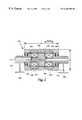
- FIG. 1is a side sectional view of a brake with an integrated flywheel in accordance with the invention.
- FIG. 2is a side sectional view of a roller embodiment in accordance with the invention.
- FIG. 1illustrates a brake device 18 according to the invention integrating a flywheel with a magnetorheological brake mechanism.
- the device 18includes a flywheel body 20 having a substantially circular profile, which is mounted on a shaft 24 for rotation.
- the flywheel body 20includes a radially outward peripheral wall 26 , a radially extending side wall 28 , and a seal 67 that cooperate to define an interior space 22 .
- the flywheel body 20has a rotational inertial mass distribution sufficient to act as a flywheel to store energy when set in rotational motion.
- a rotational inertia greater than about 0.01 KgM 2has been determined by the inventor to provide the appropriate feel when applying moderate resistance to the brake 18 , such as would be experienced during use within an exercise machine such as a stationary bike.
- Additional massmay be added to increase the inertial mass of the flywheel body 20 , for example, in the form of an annular ring 30 attached to the radially outer wall 26 as shown in FIG. 1 .
- a stationary member, or stator 40is disposed in the interior space 22 of the flywheel body 20 and is mounted to a hub 34 which is connected to a support structure 42 , for example, a frame of an exercise machine.
- the hub 34includes sealed bearings 44 mounted therein which support the shaft 24 which passes through the hub 34 .
- the shaft 24includes a coupling 50 to interconnect it to a drive source (not illustrated in FIG. 1 ), for example, a pedal apparatus, steps on a stair stepper, rollers on a ski machine.
- the drive train interconnected to coupling 50will include a one-way clutch mechanism.
- the one-way clutchmay be integrated into the coupling 50 .
- the stator 40is sized so that one or more working spaces 46 are provided between the outer, peripheral surfaces 41 of the stator 40 and the inner wall 43 of the flywheel body 20 .
- the flywheel body 20surrounds and rotates about the stator 40 .
- a controllable medium 48is disposed in the working space(s) 46 and the device 18 includes field generating means 60 for generating a magnetic field that acts between the flywheel body 20 and the stator 40 and on the working space(s) 46 .
- the field generating means 60By activating the field generating means 60 , a change in the rheology of the controllable medium 48 is effected, the controllable medium becoming increasing “thick” in response to increasing field strength.
- the controllable medium 48therefore can be controlled to provide selectable resistance to rotation of the flywheel body 20 about the stator 40 .
- the field generating means 60comprises a magnetic field coil mounted to the stator 40 , and connected to an external controller and power source by wires 62 .
- the stator 40is formed with pole piece halves 45 which cooperate to form an annular groove 63 to accommodate the coil 60 .
- the stator 40is illustrated as being shaped similar to a tire rim to provide the groove 63 .
- the field generating means 60may be a ring magnet mounted to the stator 40 in a manner similar to the coil 60 to provide a continuous resistance brake. Other orientations of mounting coils and/or magnets would be apparent.
- Both the stator 40 and the flywheel body 20include magnetically permeable (i.e., soft magnetic) material, such as low carbon steel, to provide pole pieces for the field generating means 60 .
- the stator 40 and the flywheel body 20may both be made entirely of a magnetically permeable material.
- the magnetically permeable materialmay be included in portions of the stator 40 and the flywheel body 20 which are to be acted upon by the field generating means 60 .
- the hubis made from aluminum or another nonmagnetic material.
- the controllable mediumis a powder of water atomized 410 stainless steel of 325 mesh (approximately 45 microns or smaller particle size).
- the powder mediumis disposed in the working space(s) 46 . Rotation of the flywheel body 20 readily distributes the powder throughout the working space(s) 46 adjacent to the inner periphery 43 of the radially peripheral wall 26 .
- the controllable medium 48may alternatively be formed as a suspension of magnetically soft particles in a liquid carrier, as disclosed in, for example, U.S. Pat. Nos. 5,382,373 and 5,578,238.
- a skirt 64is mounted on flywheel body 20 opposite the side wall 28 to help prevent the controllable medium 48 from packing near the bearings 44 .
- an elastomeric or plastic seal 67is formed on (preferably pressed into) the hub 34 to seal the interior space 22 of the flywheel body 20 and prevent escape of the medium 48 .
- a flywheel brake 18 as described using a dry powder mediumhas achieved in excess of 16 million cycles rotating under constant applied current.
- the longevityis at least partially attributed to the rotation of the flywheel body 20 which provides a heat sink mass to cool the medium 48 in the working space(s) 46 .
- heat in the flywheel body 20is readily transferred to the environment. Fins or other cooling mechanisms could be placed on the flywheel body 20 .
- the flywheel brake 18is most advantageous for use in exercise equipment.
- the high rotary inertia of a flywheel 20imparts smoothness to the moving parts of the equipment.
- the resistance generated by the brake 18simulates resistance encountered in the real-life equivalent to the exercise machine.
- rotational inertia of the flywheelapproximates the feeling of pedaling a bicycle up to speed and maintaining it in motion.
- brake resistancesimulates rolling friction, air resistance, and gravity (when climbing a hill).
- the flywheel brake 18may also be used as a brake in rotating equipment or in vehicles where combinations of rotary inertia and variable resistance are needed. Other uses will occur to those skilled in the art.
- FIG. 2illustrates an embodiment of the magnetorheological brake 118 with an integrated flywheel 120 in which a roller, for example, a conveyor or exercise machine roller, is the rotating body.
- the flywheel roller 120is formed as a tube, having a length 1 that is greater than its diameter d, and having a hollow interior space 122 .
- the mass of the flywheel roller 120may be selected to provide a rotational inertial mass sufficient for storing rotational energy.
- a fixed supporting shaft 124is disposed in the interior space of the roller 120 and is sized so that a working space(s) 146 is provided between the shaft 124 and an inner surface 143 of the flywheel roller 120 .
- Ball bearings 144support the roller 120 for rotation about the shaft 124 .
- the shaft 124is mounted to the conveyor frame 142 or other like frame member, such as a bicycle trainer frame or ski machine frame.
- Field generating meansare carried/mounted on the shaft 124 .
- the shaft 124includes two circumferential grooves 163 in which are mounted coils 160 for generating fields to act between the shaft 124 and the roller 120 and on the working space(s) 146 , the magnetic flux being carried in the shaft 124 and roller 120 .
- the field generating meansmay be suitably adapted, for example, to include one coil for a short shaft, or a plurality of coils for a long device.
- a controllable medium 148such as a dry powder or MR fluid, is disposed in the working space 146 .
- the fields generated by the coils 160act on the shaft 124 , roller 120 and controllable medium 148 and create resistance to rotation of the roller 120 .
- the roller brake 118can be used in conveyer systems or other similar applications.
- a roller brake 118can also be used as a resistance generating device in exercise equipment where the user's movements act to move the roller 120 , as in ski machines, and rollers for bicycles.
- the ski machineone or more rollers 120 would be disposed under, and in contact with, the ski for rotation upon skiing movements by the user.
- the rollers for bicycles applicationone or more of the rollers 120 would be positioned to contact a bicycle wheel.
- the present inventioncomprises a novel controllable device that combines a rotational energy storing flywheel with an integrated brake that can be used in a variety of applications.
- the inventionalso provides a novel controllable medium, a dry powder of soft-magnetic particles or MR fluid that provides superior performance and endurance in a flywheel brake device as described.
Landscapes
- Engineering & Computer Science (AREA)
- General Engineering & Computer Science (AREA)
- Health & Medical Sciences (AREA)
- Mechanical Engineering (AREA)
- Life Sciences & Earth Sciences (AREA)
- Biophysics (AREA)
- Orthopedic Medicine & Surgery (AREA)
- General Health & Medical Sciences (AREA)
- Physical Education & Sports Medicine (AREA)
- Braking Arrangements (AREA)
- Dynamo-Electric Clutches, Dynamo-Electric Brakes (AREA)
Abstract
Description
The invention relates to the area of braking, resistance generating, and motion control devices. Specifically, it relates to devices employing a controllable medium for motion resistance generation in rotating mechanisms.
Magnetorheological (MR) devices for damping and controlling vibration and shock are known. MR devices may be of the “rotary-acting” or “linear-acting” variety, and can advantageously provide variable controlled torques or forces, as the case may be. Known MR devices include linear dampers, rotary brakes, and rotary clutches.
MR fluid devices, for example, typically include a housing or chamber that contains a quantity of magnetically controllable fluid, with a movable member, a piston or rotor, mounted for movement through the fluid in the housing. The housing and the movable member both include a magnetically permeable pole piece. A magnetic field generator (a coil or permanent magnet) produces a magnetic field across both pole pieces for directing the magnetic flux to desired regions of the controllable fluid.
MR fluid devices employ a Magnetorheological (MR) fluid comprised of soft-magnetic particles dispersed within a liquid carrier. Typical particles include carbonyl iron, and the like, having various shapes, but which are preferably spherical and have mean diameters of between about 0.1 μm to about 500 μm. The carrier fluids include low viscosity hydraulic oils, and the like. In operation, these MR fluids exhibit a thickening behavior (a rheology change) upon being exposed to a magnetic field. The higher the magnetic field strength in the fluid, the higher the damping/restraining force or torque that can be achieved within the MR device.
MR fluid devices are disclosed in U.S. patent application Ser. No. 08/304,005 entitled “Magnetorheological Fluid Devices And Process Of Controlling Force In Exercise Equipment Utilizing Same”, U.S. patent application Ser. No. 08/613,704 entitled “Portable Controllable Fluid Rehabilitation Devices”, U.S. application Ser. No. 08/674,371 entitled “Controllable Brake”, U.S. patent application Ser. No. 08/674,179 entitled “Controllable Vibration Apparatus” and U.S. Pat. Nos. 5,547,049, 5,492,312, 5,398,917, 5,284,330, and 5,277,281, all of which are commonly assigned to the assignee of the present invention.
U.S. Pat. No. 3,962,595 to Eddens discloses a “Magnetic Particle Brake”, commonly referred to as “Dry Particle Brakes” that includes a rotating member that is disposed in an annular space in a stationary member. A field-generating coil is mounted in an outer part of the stationary member. Magnetic particles are disposed in a space between the inner part of the stationary member and the rotating member. Other magnetic particle brakes are disclosed in U.S. Pat. No. 4,350,913 to Eddens and U.S. Pat. No. 4,575,103 to Pedu.
Exercise machines such as stationary bicycles, rowers, stair climbers, and ski machines, typically rely on some kind of resistance generating device to provide adjustable resistance to the exercise movements of the user. Conventional resistance systems used in exercise machines, for example, friction devices, have deficiencies in providing reliable control of the resistance setting and in duration over repeated use of the machine. Before the present invention, however, there has been no resistance device for exercise machines using MR technology to replace conventional resistance devices and provide improved performance, reliability and endurance characteristics.
The foregoing illustrates limitations known to existing present devices and methods. Thus, it is apparent that it would be advantageous to provide an alternative directed to overcoming one or more of the limitations set forth above. Accordingly, a suitable alternative is provided including features more fully disclosed hereinafter.
The present invention provides a Magnetorheological (MR) device which combines a rotary brake with a flywheel thereby providing both resistance and rotational inertia, and can be used in an exercise apparatus and/or as a brake for rotating equipment and vehicles.
According to a preferred embodiment of the invention, a rotary brake device comprises an outer rotating member having a hollow interior space and an inner stationary member disposed in the hollow space. The rotating member, or rotor, rotates around the stationary member, or stator, an arrangement contrary to conventional practice. The stator is sized so that a small working space exists between the inner wall of the rotor and the peripheral surface(s) of the stator. The stator supports a field generating device, preferably a magnetic field producing coil. A controllable medium (a MR fluid or dry powder) is disposed in the working space so that the medium can be acted upon by the field generating device. In addition, each of the rotor and the stator is made to include a magnetically permeable portion that acts as a pole piece. Rotation of the rotor distributes the controllable medium about the inner circumference of the rotor.
Thus, according to the invention, resistance to rotation can be generated and preferably controlled by applying a magnetic field to the pole pieces and to the controllable medium in the working space. The field causes the controllable medium to thicken (a rheology change), which produces the resistance to rotation of the rotor relative to the stator.
The inventor has discovered that a controllable medium of dry powder of magnetically permeable material, such as carbonyl iron, provides a significantly high resistance force. A controllable medium formed of 410 stainless steel powder of 325 mesh particles (less than 45 microns in diameter) has been found to be particularly effective in a brake according to the invention, and has endured a test program of sixteen million cycles without failure.
The controllable medium optionally can be formed of soft-magnetic material particles included in a low-viscosity carrier of hydraulic oil.
The flywheel resistance device of the invention can be incorporated in exercise devices, such as bicycles, rowing machines, step machines, and ski machines to provide controllable, variable resistance, or in other devices/apparatus where it is desirable to have combinations of rotational inertia and resistance.
Alternatively, a device in accordance with the invention may be formed as a stationary shaft disposed in a tubular outer member, which may be useful as a brake for a conveyor system or a resistance device for a ski machine, for example.
The above-mentioned and further features, advantages, and characteristics of the present invention will become apparent from the accompanying descriptions of the preferred embodiments and attached drawings.
The accompanying drawings which form a part of the specification, illustrate several key embodiments of the present invention. The drawings and description together, serve to fully explain the invention. In the drawings,
FIG. 1 is a side sectional view of a brake with an integrated flywheel in accordance with the invention, and
FIG. 2 is a side sectional view of a roller embodiment in accordance with the invention.
Referring now to the Drawings where like numerals denote like elements, FIG. 1 illustrates abrake device 18 according to the invention integrating a flywheel with a magnetorheological brake mechanism. Thedevice 18 includes aflywheel body 20 having a substantially circular profile, which is mounted on ashaft 24 for rotation. Theflywheel body 20 includes a radially outwardperipheral wall 26, a radially extendingside wall 28, and aseal 67 that cooperate to define aninterior space 22. Theflywheel body 20 has a rotational inertial mass distribution sufficient to act as a flywheel to store energy when set in rotational motion. By way of example, and not to be considered limiting, a rotational inertia greater than about 0.01 KgM2has been determined by the inventor to provide the appropriate feel when applying moderate resistance to thebrake 18, such as would be experienced during use within an exercise machine such as a stationary bike. Additional mass may be added to increase the inertial mass of theflywheel body 20, for example, in the form of anannular ring 30 attached to the radiallyouter wall 26 as shown in FIG.1.
A stationary member, orstator 40, is disposed in theinterior space 22 of theflywheel body 20 and is mounted to ahub 34 which is connected to asupport structure 42, for example, a frame of an exercise machine. Thehub 34 includes sealedbearings 44 mounted therein which support theshaft 24 which passes through thehub 34. Theshaft 24 includes acoupling 50 to interconnect it to a drive source (not illustrated in FIG.1), for example, a pedal apparatus, steps on a stair stepper, rollers on a ski machine. Preferably, the drive train interconnected tocoupling 50 will include a one-way clutch mechanism. Optionally, the one-way clutch may be integrated into thecoupling 50. Thestator 40 is sized so that one or more workingspaces 46 are provided between the outer,peripheral surfaces 41 of thestator 40 and theinner wall 43 of theflywheel body 20. Thus, as may be understood, theflywheel body 20 surrounds and rotates about thestator 40.
According to the invention, acontrollable medium 48 is disposed in the working space(s)46 and thedevice 18 includes field generating means60 for generating a magnetic field that acts between theflywheel body 20 and thestator 40 and on the working space(s)46. By activating the field generating means60, a change in the rheology of thecontrollable medium 48 is effected, the controllable medium becoming increasing “thick” in response to increasing field strength. The controllable medium48 therefore can be controlled to provide selectable resistance to rotation of theflywheel body 20 about thestator 40.
In the illustrated embodiment, the field generating means60 comprises a magnetic field coil mounted to thestator 40, and connected to an external controller and power source bywires 62. Thestator 40 is formed with pole piece halves45 which cooperate to form anannular groove 63 to accommodate thecoil 60. In FIG. 1, thestator 40 is illustrated as being shaped similar to a tire rim to provide thegroove 63. Alternatively, the field generating means60 may be a ring magnet mounted to thestator 40 in a manner similar to thecoil 60 to provide a continuous resistance brake. Other orientations of mounting coils and/or magnets would be apparent.
Both thestator 40 and theflywheel body 20 include magnetically permeable (i.e., soft magnetic) material, such as low carbon steel, to provide pole pieces for the field generating means60. Thestator 40 and theflywheel body 20 may both be made entirely of a magnetically permeable material. Alternatively, the magnetically permeable material may be included in portions of thestator 40 and theflywheel body 20 which are to be acted upon by the field generating means60. Preferably, the hub is made from aluminum or another nonmagnetic material.
The inventor has found that a dry powder of stainless steel provides an advantageous controllable medium48. Preferably, the controllable medium is a powder of water atomized410 stainless steel of 325 mesh (approximately 45 microns or smaller particle size). The powder medium is disposed in the working space(s)46. Rotation of theflywheel body 20 readily distributes the powder throughout the working space(s)46 adjacent to theinner periphery 43 of the radiallyperipheral wall 26.
Thecontrollable medium 48 may alternatively be formed as a suspension of magnetically soft particles in a liquid carrier, as disclosed in, for example, U.S. Pat. Nos. 5,382,373 and 5,578,238.
Askirt 64 is mounted onflywheel body 20 opposite theside wall 28 to help prevent the controllable medium48 from packing near thebearings 44. In addition, an elastomeric orplastic seal 67 is formed on (preferably pressed into) thehub 34 to seal theinterior space 22 of theflywheel body 20 and prevent escape of the medium48.
In performance testing, aflywheel brake 18 as described using a dry powder medium has achieved in excess of 16 million cycles rotating under constant applied current. The longevity is at least partially attributed to the rotation of theflywheel body 20 which provides a heat sink mass to cool the medium48 in the working space(s)46. Being the outward positioned body, heat in theflywheel body 20 is readily transferred to the environment. Fins or other cooling mechanisms could be placed on theflywheel body 20.
Theflywheel brake 18 is most advantageous for use in exercise equipment. The high rotary inertia of aflywheel 20 imparts smoothness to the moving parts of the equipment. The resistance generated by thebrake 18 simulates resistance encountered in the real-life equivalent to the exercise machine. For example, in a stationary bicycle, where exertion of the user in pedaling turns the flywheel, rotational inertia of the flywheel approximates the feeling of pedaling a bicycle up to speed and maintaining it in motion. Continuing with the exercise bicycle example, brake resistance simulates rolling friction, air resistance, and gravity (when climbing a hill). Theflywheel brake 18 may also be used as a brake in rotating equipment or in vehicles where combinations of rotary inertia and variable resistance are needed. Other uses will occur to those skilled in the art.
FIG. 2 illustrates an embodiment of themagnetorheological brake 118 with anintegrated flywheel 120 in which a roller, for example, a conveyor or exercise machine roller, is the rotating body. Theflywheel roller 120 is formed as a tube, having a length 1 that is greater than its diameter d, and having a hollowinterior space 122. The mass of theflywheel roller 120 may be selected to provide a rotational inertial mass sufficient for storing rotational energy. A fixed supportingshaft 124 is disposed in the interior space of theroller 120 and is sized so that a working space(s)146 is provided between theshaft 124 and aninner surface 143 of theflywheel roller 120.Ball bearings 144 support theroller 120 for rotation about theshaft 124. Theshaft 124 is mounted to theconveyor frame 142 or other like frame member, such as a bicycle trainer frame or ski machine frame.
Field generating means are carried/mounted on theshaft 124. Theshaft 124 includes twocircumferential grooves 163 in which are mountedcoils 160 for generating fields to act between theshaft 124 and theroller 120 and on the working space(s)146, the magnetic flux being carried in theshaft 124 androller 120. Of course, depending on the length of theshaft 124 and theroller 120, and the desired braking force, the field generating means may be suitably adapted, for example, to include one coil for a short shaft, or a plurality of coils for a long device. Acontrollable medium 148, such as a dry powder or MR fluid, is disposed in the workingspace 146.
The fields generated by thecoils 160 act on theshaft 124,roller 120 andcontrollable medium 148 and create resistance to rotation of theroller 120. Theroller brake 118 can be used in conveyer systems or other similar applications. Aroller brake 118 can also be used as a resistance generating device in exercise equipment where the user's movements act to move theroller 120, as in ski machines, and rollers for bicycles. In the case of the ski machine, one ormore rollers 120 would be disposed under, and in contact with, the ski for rotation upon skiing movements by the user. In the rollers for bicycles application, one or more of therollers 120 would be positioned to contact a bicycle wheel.
In summary, it should be apparent from the foregoing that the present invention comprises a novel controllable device that combines a rotational energy storing flywheel with an integrated brake that can be used in a variety of applications. The invention also provides a novel controllable medium, a dry powder of soft-magnetic particles or MR fluid that provides superior performance and endurance in a flywheel brake device as described.
While several embodiments including the preferred embodiment of the present invention have been described in detail, various modifications, alterations, changes, and adaptations to the aforementioned may be made without departing from the scope of the present invention defined in the appended claims. It is intended that all such modifications, alterations, and changes be considered part of the present invention.
Claims (22)
1. A controllable brake, comprising:
a rotatable outer member having a hollow interior space and also having a rotational inertia, the rotatable outer member including means for altering the rotational inertia of the rotatable outer member;
a stationary inner member disposed in the hollow interior space of the rotatable member with a working space between a surface of the stationary member and a wall of the rotatable member, the stationary member defining a recess along the interior of the inner member;
selectable field generating means mounted in said stationary inner member recess and within said hollow interior space for producing a controllably variable field to act selectably between said rotatable outer member and said stationary inner member and on said working space; and
a controllable medium contained within said working space which has a rheology variably responsive to changes in the controllably variable field for controllably resisting rotation of the rotatable outer member about the stationary inner member.
2. The controllable brake of claim1, wherein the controllable medium comprises a powder of magnetically permeable material.
3. The controllable brake of claim1, wherein the controllable medium comprises a fluid of soft-magnetic particles dispersed in a fluid carrier.
4. The controllable brake of claim1, wherein said stationary member has a circular profile, and wherein said controllable medium is disposed between radially outer portions of the stationary member and an inner surface of the rotatable member.
5. The controllable brake of claim4, wherein said stationary member recess is an annular groove.
6. The controllable brake of claim1, wherein the inner member is a shaft and the outer member is tubular shaped having a length greater than a diameter, and the controllable medium is disposed between an outer surface of the shaft and an inner surface of the tubular shaped member.
7. The controllable brake of claim1, wherein said rotational inertia is greater than 0.01 KgM2.
8. The controllable brake of claim1, wherein said means for producing a field includes at least one coil.
9. The controllable brake of claim1, wherein said magnetic field generator is a permanent magnet.
10. A controllable brake of claim1 in combination with an exercise machine having a frame and a movable member which is movable relative to the frame through exertion of a user, wherein the stationary inner member is connected to the frame and the rotatable outer member is connected to the movable member.
11. The controllable brake as claimed in claim1 wherein the rotatable outer member includes an integral skirt located in the hollow interior space for preventing packing of the controllable medium in the hollow interior space.
12. The controllable brake as claimed in claim1 wherein the rotatable member includes a hub and a seal located in the hub to seal the hollow interior space and prevent escape of the controllable medium.
13. The controllable brake as claimed in claim1 further comprising: a first pole piece fixed to said inner stationary member, a second pole piece fixed to said stationary member, the first and second pole pieces defining a groove shaped to receive the selectable field generating means.
14. The controllable brake as claimed in claim1 further comprising: first and second pole pieces fixed to said inner stationary member, the first and second pole pieces defining a groove shaped to receive the selectable field generating means, the pole pieces and rotatable outer member defining working spaces, the controllable medium being disposed in the working spaces.
15. The controllable brake as claimed in claim14 wherein the pole pieces and selectable field generating means are annular.
16. A controllable brake adapted for attachment to a machine frame, comprising:
(a) a stationary inner member mounted to the machine frame, said stationary inner member having an outer radially peripheral surface, and at least one annular recess;
(b) a rotatable outer member having an interior hollow space and an inner radial peripheral surface, said inner radial peripheral surface surrounding said outer radially peripheral surface of said stationary inner member and forming therewith first and second axially extending working gaps;
(c) a plurality of bearings supporting said rotatable outer member relative to said stationary inner member and maintaining a width of said axially extending working gaps; and
(d) at least one coil mounted in the at least one annular recess of said stationary inner member and located within said interior hollow space for generating a controllably variable magnetic flux which acts upon said axially extending working gaps.
17. A controllable brake of claim16, wherein said magnetic flux path crosses a first of said axially extending working gaps, is carried axially across said rotatable outer member and then crosses a second of said axially extending working gaps.
18. A controllable brake of claim16, wherein said plurality of bearings are mounted to said stationary inner member.
19. A controllable brake of claim16, wherein said plurality of bearings are mounted between said inner member and a shaft which interconnects to said rotatable outer member.
20. A controllable brake of claim16, wherein said at least one coil further comprises a first coil mounted in a first annular recess in said inner member and a second coil mounted in a second annular recess spaced axially from said first annular recess.
21. The controllable brake as claimed in claim11 wherein the outer rotatable member includes means for adjusting the rotational inertia of the outer rotatable member.
22. The controllable brake as claimed in claim21 wherein the means for adjusting the rotational inertia of the outer rotatable member is a ring attached to the outer radially peripheral surface.
Priority Applications (2)
| Application Number | Priority Date | Filing Date | Title |
|---|---|---|---|
| US08/958,660US6186290B1 (en) | 1997-10-29 | 1997-10-29 | Magnetorheological brake with integrated flywheel |
| PCT/US1998/022623WO1999022156A1 (en) | 1997-10-29 | 1998-10-27 | Magnetorheological brake with integrated flywheel |
Applications Claiming Priority (1)
| Application Number | Priority Date | Filing Date | Title |
|---|---|---|---|
| US08/958,660US6186290B1 (en) | 1997-10-29 | 1997-10-29 | Magnetorheological brake with integrated flywheel |
Publications (1)
| Publication Number | Publication Date |
|---|---|
| US6186290B1true US6186290B1 (en) | 2001-02-13 |
Family
ID=25501170
Family Applications (1)
| Application Number | Title | Priority Date | Filing Date |
|---|---|---|---|
| US08/958,660Expired - Fee RelatedUS6186290B1 (en) | 1997-10-29 | 1997-10-29 | Magnetorheological brake with integrated flywheel |
Country Status (2)
| Country | Link |
|---|---|
| US (1) | US6186290B1 (en) |
| WO (1) | WO1999022156A1 (en) |
Cited By (94)
| Publication number | Priority date | Publication date | Assignee | Title |
|---|---|---|---|---|
| US6293375B1 (en)* | 2000-05-26 | 2001-09-25 | Chun-Feng Chen | Permanent magnet brake mechanism |
| US6478126B2 (en)* | 2000-03-03 | 2002-11-12 | Daniel Drecq | Eddy-current brake device |
| US20030019700A1 (en)* | 2001-07-25 | 2003-01-30 | Michael Wittig | Magnetorheological fluid damper |
| US6619444B2 (en)* | 2001-04-04 | 2003-09-16 | Delphi Technologies, Inc. | Magnetorheological fluid stopper at electric motor |
| US6679999B2 (en)* | 2001-03-13 | 2004-01-20 | Delphi Technologies, Inc. | MR fluids containing magnetic stainless steel |
| US6681905B2 (en) | 2001-11-30 | 2004-01-27 | Visteon Global Technologies, Inc. | Magnetorheological fluid-controlled vehicle suspension damper |
| US6702221B2 (en)* | 2002-05-07 | 2004-03-09 | Northrop Grumman Corporation | Magnetorheological fluid actively controlled bobbin tensioning apparatus |
| US20040084263A1 (en)* | 2002-11-06 | 2004-05-06 | Lord Corporation | MR device |
| US6787058B2 (en) | 2001-11-13 | 2004-09-07 | Delphi Technologies, Inc. | Low-cost MR fluids with powdered iron |
| US20040217324A1 (en)* | 2003-05-02 | 2004-11-04 | Henry Hsu | Magnetorheological fluid compositions and prosthetic knees utilizing same |
| US6837830B2 (en) | 2002-11-01 | 2005-01-04 | Mark W. Eldridge | Apparatus using multi-directional resistance in exercise equipment |
| US20050017116A1 (en)* | 2003-07-25 | 2005-01-27 | Kempf Peter C. | Electromagnetic seatbelt energy management devices |
| US6854573B2 (en) | 2001-10-25 | 2005-02-15 | Lord Corporation | Brake with field responsive material |
| US20050037633A1 (en)* | 2003-08-12 | 2005-02-17 | Shimano Inc. | Bicycle hub dynamo assembly |
| US20050098139A1 (en)* | 2003-11-06 | 2005-05-12 | Biel Michael J. | Flywheel with torsional dampening ring |
| US20050197239A1 (en)* | 2004-03-05 | 2005-09-08 | Eastman Kodak Company | Compliant pressure roller with uniform nip pressure |
| US20060065775A1 (en)* | 2004-09-30 | 2006-03-30 | Smith Douglas L | Frictional roll control apparatus for a spinning projectile |
| US7070708B2 (en) | 2004-04-30 | 2006-07-04 | Delphi Technologies, Inc. | Magnetorheological fluid resistant to settling in natural rubber devices |
| US7219449B1 (en) | 1999-05-03 | 2007-05-22 | Promdx Technology, Inc. | Adaptively controlled footwear |
| US20070181391A1 (en)* | 2001-10-25 | 2007-08-09 | St Clair Kenneth A | Brake with field responsive material |
| US20080041677A1 (en)* | 2004-12-09 | 2008-02-21 | Namuduri Chandra S | Magnetorheological device and system and method for using the same |
| US20080150458A1 (en)* | 2006-12-22 | 2008-06-26 | Nokia Corporation | Adjustable brake device |
| US20080234908A1 (en)* | 2007-03-07 | 2008-09-25 | St Clair Kenneth A | Operator input device for controlling a vehicle operation |
| US7436090B1 (en) | 2004-03-23 | 2008-10-14 | The United States Of America As Represented By The Secretary Of The Navy | Direct drive hybrid rotary motor |
| US20090218897A1 (en)* | 2005-12-21 | 2009-09-03 | Thales | Damper |
| US20090266666A1 (en)* | 2008-04-29 | 2009-10-29 | Mcdaniel Andrew Joseph | Magneto-rheological clutch and wheel transmission apparatuses and methods |
| US20090266670A1 (en)* | 2008-04-29 | 2009-10-29 | Mcdaniel Andrew Joseph | Magneto-rheological brake-clutch apparatuses and methods |
| US20090294222A1 (en)* | 2006-05-22 | 2009-12-03 | Zbigniew Piech | Roller guide with speed dependent stiffness |
| US20090302516A1 (en)* | 2008-06-05 | 2009-12-10 | Lockheed Martin Corporation | System, method and apparatus for control surface with dynamic compensation |
| US20100051374A1 (en)* | 2006-12-22 | 2010-03-04 | Lord Corporation | Operator interface controllable brake with field responsive material |
| US20100050620A1 (en)* | 2008-08-28 | 2010-03-04 | Caterpillar Inc. | Control system and method for braking a hydrostatic drive machine |
| US20110002857A1 (en)* | 2003-08-04 | 2011-01-06 | Foamix Ltd. | Oleaginous pharmaceutical and cosmetic foam |
| WO2011005409A1 (en) | 2009-07-08 | 2011-01-13 | National Oilwell Varco L.P. | Engine clutch and method of using same |
| WO2012154466A1 (en)* | 2011-05-06 | 2012-11-15 | Washington State University Research Foundation | Magnetorheological devices and associated methods of control |
| CN103075443A (en)* | 2013-01-03 | 2013-05-01 | 郑运婷 | Magnetofluid brake drum device |
| WO2013192048A1 (en) | 2012-06-18 | 2013-12-27 | Habing Douglas John | Hybrid resistance system |
| US20140024499A1 (en)* | 2012-07-23 | 2014-01-23 | Icon Health & Fitness, Inc. | Elliptical Exercise Device with Vibration Capabilities |
| CN103758912A (en)* | 2014-01-03 | 2014-04-30 | 哈尔滨工程大学 | Electrorheological fluid torsional vibration damper |
| US20140152066A1 (en)* | 2012-06-12 | 2014-06-05 | Gregory J. Hiemenz | Failsafe magnetorheological (mr) energy absorber |
| WO2014106451A1 (en)* | 2013-01-03 | 2014-07-10 | Yang Guohui | Magnetic fluid buoyancy brake drum |
| WO2014106448A1 (en)* | 2013-01-03 | 2014-07-10 | Yang Guohui | Magnetic fluid brake drum |
| WO2014106452A1 (en)* | 2013-01-03 | 2014-07-10 | Yang Guohui | Magnetic fluid buoyancy brake drum device |
| JP2014142016A (en)* | 2013-01-24 | 2014-08-07 | Somic Ishikawa Inc | Brake device |
| JP2014149857A (en)* | 2008-04-29 | 2014-08-21 | Commissariat A L'energie Atomique & Aux Energies Alternatives | Force feedback interface improving operation feeling |
| CN104641140A (en)* | 2013-01-03 | 2015-05-20 | 朱洪华 | Brake drum |
| US20150136548A1 (en)* | 2012-05-22 | 2015-05-21 | Kabushiki Kaisha Somic Ishikawa | Braking device |
| US9278249B2 (en) | 2012-07-23 | 2016-03-08 | Icon Health & Fitness, Inc. | Exercise cycle with vibration capabilities |
| US9289648B2 (en) | 2012-07-23 | 2016-03-22 | Icon Health & Fitness, Inc. | Treadmill with deck vibration |
| CN105673685A (en)* | 2016-03-14 | 2016-06-15 | 西安理工大学 | Active regulating and controlling device for bearing clearance of high-speed spindle system |
| EP3278844A1 (en)* | 2016-08-05 | 2018-02-07 | Giant Manufacturing Co., Ltd. | Magneto-rheological fluid rotary resistance device |
| CN108700907A (en)* | 2016-02-18 | 2018-10-23 | 阿尔卑斯电气株式会社 | Operating device |
| US10188890B2 (en) | 2013-12-26 | 2019-01-29 | Icon Health & Fitness, Inc. | Magnetic resistance mechanism in a cable machine |
| WO2018194468A3 (en)* | 2017-02-06 | 2019-02-28 | Universidad Tecnológica De Panamá | Multi-use portable exercise machine having rotary damper |
| US10220259B2 (en) | 2012-01-05 | 2019-03-05 | Icon Health & Fitness, Inc. | System and method for controlling an exercise device |
| US10226396B2 (en) | 2014-06-20 | 2019-03-12 | Icon Health & Fitness, Inc. | Post workout massage device |
| US10252109B2 (en) | 2016-05-13 | 2019-04-09 | Icon Health & Fitness, Inc. | Weight platform treadmill |
| US10258828B2 (en) | 2015-01-16 | 2019-04-16 | Icon Health & Fitness, Inc. | Controls for an exercise device |
| US10272317B2 (en) | 2016-03-18 | 2019-04-30 | Icon Health & Fitness, Inc. | Lighted pace feature in a treadmill |
| US10279212B2 (en) | 2013-03-14 | 2019-05-07 | Icon Health & Fitness, Inc. | Strength training apparatus with flywheel and related methods |
| US10293211B2 (en) | 2016-03-18 | 2019-05-21 | Icon Health & Fitness, Inc. | Coordinated weight selection |
| CN109944906A (en)* | 2019-03-28 | 2019-06-28 | 吉林大学 | Semi-active control of variable inertia dual-mass flywheel based on magnetorheological fluid |
| US10343017B2 (en) | 2016-11-01 | 2019-07-09 | Icon Health & Fitness, Inc. | Distance sensor for console positioning |
| US10376736B2 (en) | 2016-10-12 | 2019-08-13 | Icon Health & Fitness, Inc. | Cooling an exercise device during a dive motor runway condition |
| US10391361B2 (en) | 2015-02-27 | 2019-08-27 | Icon Health & Fitness, Inc. | Simulating real-world terrain on an exercise device |
| US20190265799A1 (en)* | 2010-09-15 | 2019-08-29 | Inventus Engineering Gmbh | Magnetorheological transmission device |
| US10426989B2 (en) | 2014-06-09 | 2019-10-01 | Icon Health & Fitness, Inc. | Cable system incorporated into a treadmill |
| US10433612B2 (en) | 2014-03-10 | 2019-10-08 | Icon Health & Fitness, Inc. | Pressure sensor to quantify work |
| US10441844B2 (en) | 2016-07-01 | 2019-10-15 | Icon Health & Fitness, Inc. | Cooling systems and methods for exercise equipment |
| US10441840B2 (en) | 2016-03-18 | 2019-10-15 | Icon Health & Fitness, Inc. | Collapsible strength exercise machine |
| US10449416B2 (en) | 2015-08-26 | 2019-10-22 | Icon Health & Fitness, Inc. | Strength exercise mechanisms |
| US10471299B2 (en) | 2016-07-01 | 2019-11-12 | Icon Health & Fitness, Inc. | Systems and methods for cooling internal exercise equipment components |
| US10493349B2 (en) | 2016-03-18 | 2019-12-03 | Icon Health & Fitness, Inc. | Display on exercise device |
| US10500473B2 (en) | 2016-10-10 | 2019-12-10 | Icon Health & Fitness, Inc. | Console positioning |
| US10537764B2 (en) | 2015-08-07 | 2020-01-21 | Icon Health & Fitness, Inc. | Emergency stop with magnetic brake for an exercise device |
| US10543395B2 (en) | 2016-12-05 | 2020-01-28 | Icon Health & Fitness, Inc. | Offsetting treadmill deck weight during operation |
| US10561877B2 (en) | 2016-11-01 | 2020-02-18 | Icon Health & Fitness, Inc. | Drop-in pivot configuration for stationary bike |
| US10561894B2 (en) | 2016-03-18 | 2020-02-18 | Icon Health & Fitness, Inc. | Treadmill with removable supports |
| US10626944B2 (en) | 2017-04-14 | 2020-04-21 | The Chinese University Of Hong Kong | Magneto-rheological series elastic actuator |
| US10625114B2 (en) | 2016-11-01 | 2020-04-21 | Icon Health & Fitness, Inc. | Elliptical and stationary bicycle apparatus including row functionality |
| US10625137B2 (en) | 2016-03-18 | 2020-04-21 | Icon Health & Fitness, Inc. | Coordinated displays in an exercise device |
| US10661114B2 (en) | 2016-11-01 | 2020-05-26 | Icon Health & Fitness, Inc. | Body weight lift mechanism on treadmill |
| US10671705B2 (en) | 2016-09-28 | 2020-06-02 | Icon Health & Fitness, Inc. | Customizing recipe recommendations |
| US10702736B2 (en) | 2017-01-14 | 2020-07-07 | Icon Health & Fitness, Inc. | Exercise cycle |
| US10729965B2 (en) | 2017-12-22 | 2020-08-04 | Icon Health & Fitness, Inc. | Audible belt guide in a treadmill |
| US10940360B2 (en) | 2015-08-26 | 2021-03-09 | Icon Health & Fitness, Inc. | Strength exercise mechanisms |
| US10953305B2 (en) | 2015-08-26 | 2021-03-23 | Icon Health & Fitness, Inc. | Strength exercise mechanisms |
| US10976827B2 (en)* | 2010-09-15 | 2021-04-13 | Inventus Engineering Gmbh | Input device and method of operating an input device |
| US11053993B2 (en) | 2014-12-08 | 2021-07-06 | Lord Corporation | Integrated device for resistive torque generation |
| US11231078B2 (en)* | 2015-08-17 | 2022-01-25 | Ton Duc Thang University | Method and apparatus for magneto-rheological brake systems |
| US11300990B2 (en)* | 2015-03-31 | 2022-04-12 | Inventus Engineering Gmbh | Input device and method for operating an input device |
| CN114382804A (en)* | 2022-01-25 | 2022-04-22 | 江苏省特种设备安全监督检验研究院 | A dual-axis independently controllable single-disc brake based on dual-coil excitation |
| US20220187048A1 (en)* | 2020-12-16 | 2022-06-16 | Bae Systems Plc | Energy harvesting assemblies |
| US11451108B2 (en) | 2017-08-16 | 2022-09-20 | Ifit Inc. | Systems and methods for axial impact resistance in electric motors |
| CN115853930A (en)* | 2022-12-05 | 2023-03-28 | 广西科技大学 | Magneto-rheological brake |
Families Citing this family (8)
| Publication number | Priority date | Publication date | Assignee | Title |
|---|---|---|---|---|
| SE0000606D0 (en)* | 2000-02-23 | 2000-02-23 | Abb Ab | Device by robot |
| AT506036B1 (en) | 2007-10-19 | 2011-10-15 | Tgw Mechanics Gmbh | CONVEYING DEVICE FOR GOODS AND METHOD FOR OPERATING SUCH A |
| DE102007055306A1 (en)* | 2007-11-20 | 2009-05-28 | Magna Powertrain Ag & Co Kg | Electric motor e.g. brush commutated direct current motor, for active rolling stabilizer of motor vehicle, has brake unit coupled with stator in torsionally fixed manner, and rheological fluid provided in area between shaft's wall and unit |
| CN103089863B (en)* | 2013-01-25 | 2015-05-27 | 中国矿业大学 | Radial extrusion type magnetorheological fluid brake |
| CN103758924B (en)* | 2014-01-22 | 2015-09-30 | 吉林大学 | Half active magnetic flow liquid double mass flywheel |
| JP7271349B2 (en)* | 2019-07-10 | 2023-05-11 | キヤノン株式会社 | Rotation resistance device and electronic device |
| EP4200535B1 (en)* | 2020-10-15 | 2025-04-23 | LORD Corporation | Drum tactile feedback device steering unit and method |
| CN114382820B (en)* | 2022-01-25 | 2023-04-28 | 江苏省特种设备安全监督检验研究院 | A dual-axis independently controllable actuator based on magnetorheological glue |
Citations (30)
| Publication number | Priority date | Publication date | Assignee | Title |
|---|---|---|---|---|
| US2575360A (en) | 1947-10-31 | 1951-11-20 | Rabinow Jacob | Magnetic fluid torque and force transmitting device |
| US2649935A (en) | 1948-09-23 | 1953-08-25 | American Steel Foundries | Magnetic railway brake |
| US2661825A (en) | 1949-01-07 | 1953-12-08 | Wefco Inc | High fidelity slip control |
| GB712908A (en) | 1950-06-02 | 1954-08-04 | British Thomson Houston Co Ltd | Improvements in and relating to magnetic fluid devices |
| US2685947A (en) | 1950-06-17 | 1954-08-10 | Vickers Inc | Clutch or brake employing magnetic particles |
| US2733792A (en) | 1956-02-07 | Clutch with magnetic fluid mixture | ||
| DE1035419B (en) | 1953-02-12 | 1958-07-31 | Eaton Mfg Co | Magnetic particle clutch or brake |
| GB1226142A (en) | 1967-02-23 | 1971-03-24 | ||
| US3739887A (en) | 1969-10-17 | 1973-06-19 | Creusot Loire | Electromagnetic powder couplings |
| US3962595A (en) | 1974-12-20 | 1976-06-08 | W. J. Industries, Incorporated | Magnetic particle brake |
| US4090161A (en)* | 1975-08-29 | 1978-05-16 | Wolfgang E. Schultz | Electromagnetic clutch or brake |
| US4123675A (en) | 1977-06-13 | 1978-10-31 | Ferrofluidics Corporation | Inertia damper using ferrofluid |
| US4350913A (en) | 1980-08-13 | 1982-09-21 | W. J. Industries, Incorporated | Magnetic particle devices |
| US4853573A (en)* | 1988-07-29 | 1989-08-01 | Eaton Corporation | Eddy current brake assembly |
| US4974706A (en)* | 1986-02-26 | 1990-12-04 | Shinko Electric Co., Ltd. | Torque limiter |
| US5015926A (en) | 1990-02-02 | 1991-05-14 | Casler John A | Electronically controlled force application mechanism for exercise machines |
| US5072930A (en) | 1990-03-02 | 1991-12-17 | Giant Manufacturing Co., Ltd. | Load applying device for an exercise bicycle |
| USRE34479E (en) | 1986-02-20 | 1993-12-14 | Minoura Carrier & Stand Works Co., Ltd. | Resistence applying means for exercising apparatus |
| US5284330A (en) | 1992-06-18 | 1994-02-08 | Lord Corporation | Magnetorheological fluid devices |
| US5382373A (en) | 1992-10-30 | 1995-01-17 | Lord Corporation | Magnetorheological materials based on alloy particles |
| US5409435A (en) | 1993-11-03 | 1995-04-25 | Daniels; John J. | Variable resistance exercise device |
| US5460585A (en) | 1994-03-11 | 1995-10-24 | B.G.M. Engineering, Inc. | Muscle training and physical rehabilitation machine using electro-rheological magnetic fluid |
| US5492312A (en) | 1995-04-17 | 1996-02-20 | Lord Corporation | Multi-degree of freedom magnetorheological devices and system for using same |
| US5547049A (en) | 1994-05-31 | 1996-08-20 | Lord Corporation | Magnetorheological fluid composite structures |
| US5598908A (en) | 1995-06-05 | 1997-02-04 | Gse, Inc. | Magnetorheological fluid coupling device and torque load simulator system |
| US5816372A (en) | 1994-09-09 | 1998-10-06 | Lord Corporation | Magnetorheological fluid devices and process of controlling force in exercise equipment utilizing same |
| US5842547A (en) | 1996-07-02 | 1998-12-01 | Lord Corporation | Controllable brake |
| US5848678A (en) | 1997-06-04 | 1998-12-15 | General Motors Corporation | Passive magnetorheological clutch |
| US5896964A (en) | 1997-06-02 | 1999-04-27 | General Motors Corporation | Split rotor cooling fan clutch |
| US5896965A (en) | 1997-06-02 | 1999-04-27 | General Motors Corporation | Magnetorheological fluid fan clutch |
Family Cites Families (5)
| Publication number | Priority date | Publication date | Assignee | Title |
|---|---|---|---|---|
| FR1142319A (en)* | 1955-03-07 | 1957-09-17 | Elmeg | Magnetic coupling or powder brake |
| US4252979A (en) | 1979-01-26 | 1981-02-24 | Amchem Products Inc. | Terephthalic acid derivatives |
| US4575103A (en) | 1984-04-09 | 1986-03-11 | Pedu Alexander A | Magnetic seal for magnetic particle clutches and brakes |
| US5277281A (en) | 1992-06-18 | 1994-01-11 | Lord Corporation | Magnetorheological fluid dampers |
| US5578238A (en) | 1992-10-30 | 1996-11-26 | Lord Corporation | Magnetorheological materials utilizing surface-modified particles |
- 1997
- 1997-10-29USUS08/958,660patent/US6186290B1/ennot_activeExpired - Fee Related
- 1998
- 1998-10-27WOPCT/US1998/022623patent/WO1999022156A1/enactiveApplication Filing
Patent Citations (30)
| Publication number | Priority date | Publication date | Assignee | Title |
|---|---|---|---|---|
| US2733792A (en) | 1956-02-07 | Clutch with magnetic fluid mixture | ||
| US2575360A (en) | 1947-10-31 | 1951-11-20 | Rabinow Jacob | Magnetic fluid torque and force transmitting device |
| US2649935A (en) | 1948-09-23 | 1953-08-25 | American Steel Foundries | Magnetic railway brake |
| US2661825A (en) | 1949-01-07 | 1953-12-08 | Wefco Inc | High fidelity slip control |
| GB712908A (en) | 1950-06-02 | 1954-08-04 | British Thomson Houston Co Ltd | Improvements in and relating to magnetic fluid devices |
| US2685947A (en) | 1950-06-17 | 1954-08-10 | Vickers Inc | Clutch or brake employing magnetic particles |
| DE1035419B (en) | 1953-02-12 | 1958-07-31 | Eaton Mfg Co | Magnetic particle clutch or brake |
| GB1226142A (en) | 1967-02-23 | 1971-03-24 | ||
| US3739887A (en) | 1969-10-17 | 1973-06-19 | Creusot Loire | Electromagnetic powder couplings |
| US3962595A (en) | 1974-12-20 | 1976-06-08 | W. J. Industries, Incorporated | Magnetic particle brake |
| US4090161A (en)* | 1975-08-29 | 1978-05-16 | Wolfgang E. Schultz | Electromagnetic clutch or brake |
| US4123675A (en) | 1977-06-13 | 1978-10-31 | Ferrofluidics Corporation | Inertia damper using ferrofluid |
| US4350913A (en) | 1980-08-13 | 1982-09-21 | W. J. Industries, Incorporated | Magnetic particle devices |
| USRE34479E (en) | 1986-02-20 | 1993-12-14 | Minoura Carrier & Stand Works Co., Ltd. | Resistence applying means for exercising apparatus |
| US4974706A (en)* | 1986-02-26 | 1990-12-04 | Shinko Electric Co., Ltd. | Torque limiter |
| US4853573A (en)* | 1988-07-29 | 1989-08-01 | Eaton Corporation | Eddy current brake assembly |
| US5015926A (en) | 1990-02-02 | 1991-05-14 | Casler John A | Electronically controlled force application mechanism for exercise machines |
| US5072930A (en) | 1990-03-02 | 1991-12-17 | Giant Manufacturing Co., Ltd. | Load applying device for an exercise bicycle |
| US5284330A (en) | 1992-06-18 | 1994-02-08 | Lord Corporation | Magnetorheological fluid devices |
| US5382373A (en) | 1992-10-30 | 1995-01-17 | Lord Corporation | Magnetorheological materials based on alloy particles |
| US5409435A (en) | 1993-11-03 | 1995-04-25 | Daniels; John J. | Variable resistance exercise device |
| US5460585A (en) | 1994-03-11 | 1995-10-24 | B.G.M. Engineering, Inc. | Muscle training and physical rehabilitation machine using electro-rheological magnetic fluid |
| US5547049A (en) | 1994-05-31 | 1996-08-20 | Lord Corporation | Magnetorheological fluid composite structures |
| US5816372A (en) | 1994-09-09 | 1998-10-06 | Lord Corporation | Magnetorheological fluid devices and process of controlling force in exercise equipment utilizing same |
| US5492312A (en) | 1995-04-17 | 1996-02-20 | Lord Corporation | Multi-degree of freedom magnetorheological devices and system for using same |
| US5598908A (en) | 1995-06-05 | 1997-02-04 | Gse, Inc. | Magnetorheological fluid coupling device and torque load simulator system |
| US5842547A (en) | 1996-07-02 | 1998-12-01 | Lord Corporation | Controllable brake |
| US5896964A (en) | 1997-06-02 | 1999-04-27 | General Motors Corporation | Split rotor cooling fan clutch |
| US5896965A (en) | 1997-06-02 | 1999-04-27 | General Motors Corporation | Magnetorheological fluid fan clutch |
| US5848678A (en) | 1997-06-04 | 1998-12-15 | General Motors Corporation | Passive magnetorheological clutch |
Non-Patent Citations (6)
| Title |
|---|
| Carlson et al., Commercial Magneto-Rheological Fluid Devices, Lord Library of Technical Articles, 1995. |
| Magnetic Power Systems, Inc.'s Brochure re: FASTEP Magnetic Particle Clutches and Brakes. |
| Magnetic Power Systems, Inc.'s Brochure re: Sofstep Magnetic Particle Clutches and Brakes. |
| Placid Instrusties, Inc.'s Brochure Re: Magnetic Particle Clutches and Brakes. |
| Rheonetic Magnetic Fluids & System Brochure, Feb. 1997. |
| Warner Electric's Brochure re: Warner Electromagnetic Particle Clutches and Brakes. |
Cited By (133)
| Publication number | Priority date | Publication date | Assignee | Title |
|---|---|---|---|---|
| US7219449B1 (en) | 1999-05-03 | 2007-05-22 | Promdx Technology, Inc. | Adaptively controlled footwear |
| US6478126B2 (en)* | 2000-03-03 | 2002-11-12 | Daniel Drecq | Eddy-current brake device |
| US6293375B1 (en)* | 2000-05-26 | 2001-09-25 | Chun-Feng Chen | Permanent magnet brake mechanism |
| US6679999B2 (en)* | 2001-03-13 | 2004-01-20 | Delphi Technologies, Inc. | MR fluids containing magnetic stainless steel |
| US6619444B2 (en)* | 2001-04-04 | 2003-09-16 | Delphi Technologies, Inc. | Magnetorheological fluid stopper at electric motor |
| US20030019700A1 (en)* | 2001-07-25 | 2003-01-30 | Michael Wittig | Magnetorheological fluid damper |
| US6854573B2 (en) | 2001-10-25 | 2005-02-15 | Lord Corporation | Brake with field responsive material |
| US7198140B2 (en) | 2001-10-25 | 2007-04-03 | Lord Corporation | Brake with field responsive material |
| US20050126871A1 (en)* | 2001-10-25 | 2005-06-16 | Lord Corporation | Brake with field responsive material |
| US20070181391A1 (en)* | 2001-10-25 | 2007-08-09 | St Clair Kenneth A | Brake with field responsive material |
| US8397883B2 (en) | 2001-10-25 | 2013-03-19 | Lord Corporation | Brake with field responsive material |
| US6787058B2 (en) | 2001-11-13 | 2004-09-07 | Delphi Technologies, Inc. | Low-cost MR fluids with powdered iron |
| US6681905B2 (en) | 2001-11-30 | 2004-01-27 | Visteon Global Technologies, Inc. | Magnetorheological fluid-controlled vehicle suspension damper |
| DE10218320B4 (en)* | 2001-11-30 | 2006-06-01 | Visteon Global Technologies, Inc., Dearborn | Magneto-rheological fluid damper for vehicle wheel suspensions |
| US6702221B2 (en)* | 2002-05-07 | 2004-03-09 | Northrop Grumman Corporation | Magnetorheological fluid actively controlled bobbin tensioning apparatus |
| US6837830B2 (en) | 2002-11-01 | 2005-01-04 | Mark W. Eldridge | Apparatus using multi-directional resistance in exercise equipment |
| US6886819B2 (en)* | 2002-11-06 | 2005-05-03 | Lord Corporation | MR fluid for increasing the output of a magnetorheological fluid damper |
| US20040084263A1 (en)* | 2002-11-06 | 2004-05-06 | Lord Corporation | MR device |
| US7335233B2 (en) | 2003-05-02 | 2008-02-26 | Ossur Hf | Magnetorheological fluid compositions and prosthetic knees utilizing same |
| US20040217324A1 (en)* | 2003-05-02 | 2004-11-04 | Henry Hsu | Magnetorheological fluid compositions and prosthetic knees utilizing same |
| US20060178753A1 (en)* | 2003-05-02 | 2006-08-10 | Henry Hsu | Magnetorheological fluid compositions and prosthetic knees utilizing same |
| US20060197051A1 (en)* | 2003-05-02 | 2006-09-07 | Henry Hsu | Magnetorheological fluid compositions and prosthetic knees utilizing same |
| US7101487B2 (en) | 2003-05-02 | 2006-09-05 | Ossur Engineering, Inc. | Magnetorheological fluid compositions and prosthetic knees utilizing same |
| US20050017116A1 (en)* | 2003-07-25 | 2005-01-27 | Kempf Peter C. | Electromagnetic seatbelt energy management devices |
| US6863236B2 (en) | 2003-07-25 | 2005-03-08 | Key Safety Systems, Inc. | Electromagnetic seatbelt energy management devices |
| WO2005016706A1 (en)* | 2003-07-25 | 2005-02-24 | Key Safety Systems, Inc. | Electromagnetic seatbelt energy management devices |
| US20110002857A1 (en)* | 2003-08-04 | 2011-01-06 | Foamix Ltd. | Oleaginous pharmaceutical and cosmetic foam |
| US7048546B2 (en)* | 2003-08-12 | 2006-05-23 | Shimano Inc. | Bicycle hub dynamo assembly |
| US20050037633A1 (en)* | 2003-08-12 | 2005-02-17 | Shimano Inc. | Bicycle hub dynamo assembly |
| US20050098139A1 (en)* | 2003-11-06 | 2005-05-12 | Biel Michael J. | Flywheel with torsional dampening ring |
| US7073474B2 (en) | 2003-11-06 | 2006-07-11 | Brp Us Inc. | Flywheel with torsional dampening ring |
| US7258654B2 (en)* | 2004-03-05 | 2007-08-21 | Rohm and Haas Dënmark Finance A/S | Compliant pressure roller with uniform nip pressure |
| US20070232469A1 (en)* | 2004-03-05 | 2007-10-04 | Bomba Richard D | Compliant pressure roller with uniform nip pressure |
| US20050197239A1 (en)* | 2004-03-05 | 2005-09-08 | Eastman Kodak Company | Compliant pressure roller with uniform nip pressure |
| US7662078B2 (en) | 2004-03-05 | 2010-02-16 | Skc Haas Display Films Co., Ltd. | Method for creating a uniform nip pressure utilizing a compliant pressure roller |
| US7436090B1 (en) | 2004-03-23 | 2008-10-14 | The United States Of America As Represented By The Secretary Of The Navy | Direct drive hybrid rotary motor |
| US7070708B2 (en) | 2004-04-30 | 2006-07-04 | Delphi Technologies, Inc. | Magnetorheological fluid resistant to settling in natural rubber devices |
| US7412930B2 (en) | 2004-09-30 | 2008-08-19 | General Dynamic Ordnance And Tactical Systems, Inc. | Frictional roll control apparatus for a spinning projectile |
| US20060065775A1 (en)* | 2004-09-30 | 2006-03-30 | Smith Douglas L | Frictional roll control apparatus for a spinning projectile |
| US20080041677A1 (en)* | 2004-12-09 | 2008-02-21 | Namuduri Chandra S | Magnetorheological device and system and method for using the same |
| DE102005058254B4 (en)* | 2004-12-09 | 2014-02-13 | General Motors Corp. | Magnetorheological device and magnetorheological system and method of using the same |
| US7686143B2 (en) | 2004-12-09 | 2010-03-30 | Gm Global Technology Operations, Inc. | Magnetorheological device and system and method for using the same |
| US20090218897A1 (en)* | 2005-12-21 | 2009-09-03 | Thales | Damper |
| US20090294222A1 (en)* | 2006-05-22 | 2009-12-03 | Zbigniew Piech | Roller guide with speed dependent stiffness |
| US9193565B2 (en)* | 2006-05-22 | 2015-11-24 | Otis Elevator Company | Roller guide with speed dependent stiffness |
| US20080150458A1 (en)* | 2006-12-22 | 2008-06-26 | Nokia Corporation | Adjustable brake device |
| US20100051374A1 (en)* | 2006-12-22 | 2010-03-04 | Lord Corporation | Operator interface controllable brake with field responsive material |
| US8353393B2 (en) | 2006-12-22 | 2013-01-15 | Lord Corporation | Operator interface controllable brake with field responsive material |
| US20080234908A1 (en)* | 2007-03-07 | 2008-09-25 | St Clair Kenneth A | Operator input device for controlling a vehicle operation |
| US7891474B2 (en) | 2008-04-29 | 2011-02-22 | Honda Motor Co., Ltd. | Magneto-rheological brake-clutch apparatuses and methods |
| JP2014149857A (en)* | 2008-04-29 | 2014-08-21 | Commissariat A L'energie Atomique & Aux Energies Alternatives | Force feedback interface improving operation feeling |
| US8016092B2 (en) | 2008-04-29 | 2011-09-13 | Honda Motor Co., Ltd. | Magneto-rheological clutch and wheel transmission apparatuses and methods |
| US20090266670A1 (en)* | 2008-04-29 | 2009-10-29 | Mcdaniel Andrew Joseph | Magneto-rheological brake-clutch apparatuses and methods |
| US20090266666A1 (en)* | 2008-04-29 | 2009-10-29 | Mcdaniel Andrew Joseph | Magneto-rheological clutch and wheel transmission apparatuses and methods |
| US20090302516A1 (en)* | 2008-06-05 | 2009-12-10 | Lockheed Martin Corporation | System, method and apparatus for control surface with dynamic compensation |
| US8261544B2 (en) | 2008-08-28 | 2012-09-11 | Caterpillar Inc. | Control system and method for braking a hydrostatic drive machine |
| US20100050620A1 (en)* | 2008-08-28 | 2010-03-04 | Caterpillar Inc. | Control system and method for braking a hydrostatic drive machine |
| WO2011005409A1 (en) | 2009-07-08 | 2011-01-13 | National Oilwell Varco L.P. | Engine clutch and method of using same |
| US8235195B2 (en) | 2009-07-08 | 2012-08-07 | National Oilwell Varco, L.P. | Engine clutch and method of using same |
| US20110005884A1 (en)* | 2009-07-08 | 2011-01-13 | National Oilwell Varco | Engine Clutch and Method of Using Same |
| US10976827B2 (en)* | 2010-09-15 | 2021-04-13 | Inventus Engineering Gmbh | Input device and method of operating an input device |
| US10671171B2 (en)* | 2010-09-15 | 2020-06-02 | Inventus Engineering Gmbh | Magnetorheological transmission device |
| US20190265799A1 (en)* | 2010-09-15 | 2019-08-29 | Inventus Engineering Gmbh | Magnetorheological transmission device |
| US9093214B2 (en) | 2011-05-06 | 2015-07-28 | Washington State University | Magnetorheological devices and associated methods of control |
| WO2012154466A1 (en)* | 2011-05-06 | 2012-11-15 | Washington State University Research Foundation | Magnetorheological devices and associated methods of control |
| US10220259B2 (en) | 2012-01-05 | 2019-03-05 | Icon Health & Fitness, Inc. | System and method for controlling an exercise device |
| US9410588B2 (en)* | 2012-05-22 | 2016-08-09 | Kabushiki Kaisha Sonic Ishikawa | Braking device |
| US20150136548A1 (en)* | 2012-05-22 | 2015-05-21 | Kabushiki Kaisha Somic Ishikawa | Braking device |
| US20140152066A1 (en)* | 2012-06-12 | 2014-06-05 | Gregory J. Hiemenz | Failsafe magnetorheological (mr) energy absorber |
| US9109654B2 (en)* | 2012-06-12 | 2015-08-18 | Inno Vital Systems, Inc. | Failsafe magnetorheological (MR) energy absorber |
| WO2013192048A1 (en) | 2012-06-18 | 2013-12-27 | Habing Douglas John | Hybrid resistance system |
| US9289648B2 (en) | 2012-07-23 | 2016-03-22 | Icon Health & Fitness, Inc. | Treadmill with deck vibration |
| US20140024499A1 (en)* | 2012-07-23 | 2014-01-23 | Icon Health & Fitness, Inc. | Elliptical Exercise Device with Vibration Capabilities |
| US9278249B2 (en) | 2012-07-23 | 2016-03-08 | Icon Health & Fitness, Inc. | Exercise cycle with vibration capabilities |
| WO2014106448A1 (en)* | 2013-01-03 | 2014-07-10 | Yang Guohui | Magnetic fluid brake drum |
| CN103075443B (en)* | 2013-01-03 | 2015-05-20 | 郑运婷 | Magnetofluid brake drum device |
| CN104641140A (en)* | 2013-01-03 | 2015-05-20 | 朱洪华 | Brake drum |
| WO2014106450A1 (en)* | 2013-01-03 | 2014-07-10 | Yang Guohui | Magnetic fluid brake drum device |
| WO2014106452A1 (en)* | 2013-01-03 | 2014-07-10 | Yang Guohui | Magnetic fluid buoyancy brake drum device |
| CN104718395A (en)* | 2013-01-03 | 2015-06-17 | 张有基 | Magnetic fluid brake drum |
| WO2014106451A1 (en)* | 2013-01-03 | 2014-07-10 | Yang Guohui | Magnetic fluid buoyancy brake drum |
| CN103075443A (en)* | 2013-01-03 | 2013-05-01 | 郑运婷 | Magnetofluid brake drum device |
| JP2014142016A (en)* | 2013-01-24 | 2014-08-07 | Somic Ishikawa Inc | Brake device |
| US10279212B2 (en) | 2013-03-14 | 2019-05-07 | Icon Health & Fitness, Inc. | Strength training apparatus with flywheel and related methods |
| US10188890B2 (en) | 2013-12-26 | 2019-01-29 | Icon Health & Fitness, Inc. | Magnetic resistance mechanism in a cable machine |
| CN103758912A (en)* | 2014-01-03 | 2014-04-30 | 哈尔滨工程大学 | Electrorheological fluid torsional vibration damper |
| US10433612B2 (en) | 2014-03-10 | 2019-10-08 | Icon Health & Fitness, Inc. | Pressure sensor to quantify work |
| US10426989B2 (en) | 2014-06-09 | 2019-10-01 | Icon Health & Fitness, Inc. | Cable system incorporated into a treadmill |
| US10226396B2 (en) | 2014-06-20 | 2019-03-12 | Icon Health & Fitness, Inc. | Post workout massage device |
| US11053993B2 (en) | 2014-12-08 | 2021-07-06 | Lord Corporation | Integrated device for resistive torque generation |
| US10258828B2 (en) | 2015-01-16 | 2019-04-16 | Icon Health & Fitness, Inc. | Controls for an exercise device |
| US10391361B2 (en) | 2015-02-27 | 2019-08-27 | Icon Health & Fitness, Inc. | Simulating real-world terrain on an exercise device |
| US11300990B2 (en)* | 2015-03-31 | 2022-04-12 | Inventus Engineering Gmbh | Input device and method for operating an input device |
| US10537764B2 (en) | 2015-08-07 | 2020-01-21 | Icon Health & Fitness, Inc. | Emergency stop with magnetic brake for an exercise device |
| US11231078B2 (en)* | 2015-08-17 | 2022-01-25 | Ton Duc Thang University | Method and apparatus for magneto-rheological brake systems |
| US10940360B2 (en) | 2015-08-26 | 2021-03-09 | Icon Health & Fitness, Inc. | Strength exercise mechanisms |
| US10449416B2 (en) | 2015-08-26 | 2019-10-22 | Icon Health & Fitness, Inc. | Strength exercise mechanisms |
| US10953305B2 (en) | 2015-08-26 | 2021-03-23 | Icon Health & Fitness, Inc. | Strength exercise mechanisms |
| US20180320750A1 (en)* | 2016-02-18 | 2018-11-08 | Alps Electric Co., Ltd. | Manipulation device |
| US10900535B2 (en)* | 2016-02-18 | 2021-01-26 | Alps Alpine Co., Ltd. | Manipulation device |
| CN108700907A (en)* | 2016-02-18 | 2018-10-23 | 阿尔卑斯电气株式会社 | Operating device |
| CN105673685B (en)* | 2016-03-14 | 2017-12-29 | 西安理工大学 | A kind of active regulation device of the bearing clearance of high-speed spindle system |
| CN105673685A (en)* | 2016-03-14 | 2016-06-15 | 西安理工大学 | Active regulating and controlling device for bearing clearance of high-speed spindle system |
| US10441840B2 (en) | 2016-03-18 | 2019-10-15 | Icon Health & Fitness, Inc. | Collapsible strength exercise machine |
| US10561894B2 (en) | 2016-03-18 | 2020-02-18 | Icon Health & Fitness, Inc. | Treadmill with removable supports |
| US10272317B2 (en) | 2016-03-18 | 2019-04-30 | Icon Health & Fitness, Inc. | Lighted pace feature in a treadmill |
| US10493349B2 (en) | 2016-03-18 | 2019-12-03 | Icon Health & Fitness, Inc. | Display on exercise device |
| US10625137B2 (en) | 2016-03-18 | 2020-04-21 | Icon Health & Fitness, Inc. | Coordinated displays in an exercise device |
| US10293211B2 (en) | 2016-03-18 | 2019-05-21 | Icon Health & Fitness, Inc. | Coordinated weight selection |
| US10252109B2 (en) | 2016-05-13 | 2019-04-09 | Icon Health & Fitness, Inc. | Weight platform treadmill |
| US10471299B2 (en) | 2016-07-01 | 2019-11-12 | Icon Health & Fitness, Inc. | Systems and methods for cooling internal exercise equipment components |
| US10441844B2 (en) | 2016-07-01 | 2019-10-15 | Icon Health & Fitness, Inc. | Cooling systems and methods for exercise equipment |
| US20180036572A1 (en)* | 2016-08-05 | 2018-02-08 | Giant Manufacturing Co., Ltd. | Magneto-rheological fluid rotary resistance device |
| US10207138B2 (en)* | 2016-08-05 | 2019-02-19 | Giant Manufacturing Co., Ltd. | Magneto-rheological fluid rotary resistance device |
| EP3278844A1 (en)* | 2016-08-05 | 2018-02-07 | Giant Manufacturing Co., Ltd. | Magneto-rheological fluid rotary resistance device |
| US10671705B2 (en) | 2016-09-28 | 2020-06-02 | Icon Health & Fitness, Inc. | Customizing recipe recommendations |
| US10500473B2 (en) | 2016-10-10 | 2019-12-10 | Icon Health & Fitness, Inc. | Console positioning |
| US10376736B2 (en) | 2016-10-12 | 2019-08-13 | Icon Health & Fitness, Inc. | Cooling an exercise device during a dive motor runway condition |
| US10561877B2 (en) | 2016-11-01 | 2020-02-18 | Icon Health & Fitness, Inc. | Drop-in pivot configuration for stationary bike |
| US10343017B2 (en) | 2016-11-01 | 2019-07-09 | Icon Health & Fitness, Inc. | Distance sensor for console positioning |
| US10661114B2 (en) | 2016-11-01 | 2020-05-26 | Icon Health & Fitness, Inc. | Body weight lift mechanism on treadmill |
| US10625114B2 (en) | 2016-11-01 | 2020-04-21 | Icon Health & Fitness, Inc. | Elliptical and stationary bicycle apparatus including row functionality |
| US10543395B2 (en) | 2016-12-05 | 2020-01-28 | Icon Health & Fitness, Inc. | Offsetting treadmill deck weight during operation |
| US10702736B2 (en) | 2017-01-14 | 2020-07-07 | Icon Health & Fitness, Inc. | Exercise cycle |
| WO2018194468A3 (en)* | 2017-02-06 | 2019-02-28 | Universidad Tecnológica De Panamá | Multi-use portable exercise machine having rotary damper |
| US10626944B2 (en) | 2017-04-14 | 2020-04-21 | The Chinese University Of Hong Kong | Magneto-rheological series elastic actuator |
| US11451108B2 (en) | 2017-08-16 | 2022-09-20 | Ifit Inc. | Systems and methods for axial impact resistance in electric motors |
| US10729965B2 (en) | 2017-12-22 | 2020-08-04 | Icon Health & Fitness, Inc. | Audible belt guide in a treadmill |
| CN109944906A (en)* | 2019-03-28 | 2019-06-28 | 吉林大学 | Semi-active control of variable inertia dual-mass flywheel based on magnetorheological fluid |
| US20220187048A1 (en)* | 2020-12-16 | 2022-06-16 | Bae Systems Plc | Energy harvesting assemblies |
| US12152866B2 (en)* | 2020-12-16 | 2024-11-26 | Bae Systems Plc | Energy harvesting assemblies |
| CN114382804A (en)* | 2022-01-25 | 2022-04-22 | 江苏省特种设备安全监督检验研究院 | A dual-axis independently controllable single-disc brake based on dual-coil excitation |
| CN115853930A (en)* | 2022-12-05 | 2023-03-28 | 广西科技大学 | Magneto-rheological brake |
Also Published As
| Publication number | Publication date |
|---|---|
| WO1999022156A1 (en) | 1999-05-06 |
Similar Documents
| Publication | Publication Date | Title |
|---|---|---|
| US6186290B1 (en) | Magnetorheological brake with integrated flywheel | |
| US6340080B1 (en) | Apparatus including a matrix structure and apparatus | |
| EP1025373B1 (en) | Controllable medium device and apparatus utilizing same | |
| JPH10506175A (en) | Magnetorheological fluid device and force control method using the training device using the device | |
| CA3007550C (en) | Braking mechanisms | |
| US7624850B2 (en) | Damping device having controllable resistive force | |
| US5573088A (en) | Controllable resistance device and force dampener, and vehicle utilizing the same | |
| US5460585A (en) | Muscle training and physical rehabilitation machine using electro-rheological magnetic fluid | |
| US7198140B2 (en) | Brake with field responsive material | |
| US7232016B2 (en) | Fluid damper having continuously variable damping response | |
| WO1998039577A1 (en) | Passive magnetorheological fluid device with excursion dependent characteristic | |
| WO2000067851A2 (en) | Controllable device having a matrix medium retaining structure | |
| TW201805544A (en) | Rotation-type resisting device having magnetorheological fluid used for providing a relative rotating motion between an inertia wheel and a shaft core, and comprises an inner stator, an outer rotor, an electric conductive wire and a magnetorheological fluid | |
| EP0900579B1 (en) | Variable resistance device for bicycle trainer | |
| US9393475B2 (en) | Progressive resistance system for an exercise device | |
| CN107477131B (en) | Screw pump magneto-rheological damper and its spinning bicycle | |
| KR100311735B1 (en) | Brake apparatus used as load unit by using magneto-rheological fluid | |
| CN201143359Y (en) | Magneto-rheological moment bicycle exercise machine | |
| US20040130228A1 (en) | Magnetic induction coupler | |
| RU2525806C1 (en) | Device for creating load | |
| US20230096156A1 (en) | Indoor exercise bike having uphill and downhill mode functions | |
| CN216169690U (en) | Flywheel resistance adjustment mechanism and spinning | |
| EP2859922B1 (en) | Progressive resistance system for an exercise device | |
| RU2135243C1 (en) | Electrically controlled magnetic-dispersed brake and loader for exercisers with electrically controlled magnetic-dispersed brake | |
| AU2013242869B2 (en) | Progressive resistance device for an exercise device |
Legal Events
| Date | Code | Title | Description |
|---|---|---|---|
| AS | Assignment | Owner name:LORD CORPORATION, NORTH CAROLINA Free format text:ASSIGNMENT OF ASSIGNORS INTEREST;ASSIGNOR:CARLSON, J. DAVID;REEL/FRAME:009132/0521 Effective date:19971215 | |
| FPAY | Fee payment | Year of fee payment:4 | |
| FPAY | Fee payment | Year of fee payment:8 | |
| REMI | Maintenance fee reminder mailed | ||
| LAPS | Lapse for failure to pay maintenance fees | ||
| STCH | Information on status: patent discontinuation | Free format text:PATENT EXPIRED DUE TO NONPAYMENT OF MAINTENANCE FEES UNDER 37 CFR 1.362 | |
| FP | Lapsed due to failure to pay maintenance fee | Effective date:20130213 |